Distribution of the Analog or Digital FM Composite Multiplex Signal … · 2016-04-28 · Analog or...
32
Distribution of the Analog or Digital FM Composite Multiplex Signal across IP Networks April 17, 2016 NAB Show 2016 Featuring GatesAir’s Junius Kim Hardware Engineer Keyur Parikh Architect / Software Lead Copyright © 2016 GatesAir, Inc. All rights reserved.
Transcript of Distribution of the Analog or Digital FM Composite Multiplex Signal … · 2016-04-28 · Analog or...

Distribution of theAnalog or Digital FM Composite
Multiplex Signal across IP NetworksApril 17, 2016
NAB Show 2016
FeaturingGatesAir’s
Junius KimHardware Engineer
Keyur ParikhArchitect / Software Lead
Copyright © 2016 GatesAir, Inc. All rights reserved.


Distribution of the Analog or Digital FM Composite Multiplex Signal across IP Networks
Junius Kim and Keyur ParikhGatesAir
Mason, Ohio

FM MPX Generation
• L+R• 19 kHz pilot tone• L-R – 38 kHz subcarrier• Radio Data System (RDS) -
low bit rate (1187 bps) digital data – 57 kHz subcarrier

FM MPX Frequency Spectrum• Pilot tone decoded at
receiver• Subsidiary Communication
Authorization – Low BW audio
• 67 and 92 kHz Subcarriers• FM MPX BW
• 53 kHz: L and R audio• 60 kHz: plus RDS• 75 kHz: plus one SCA• 99 kHz: plus one SCA
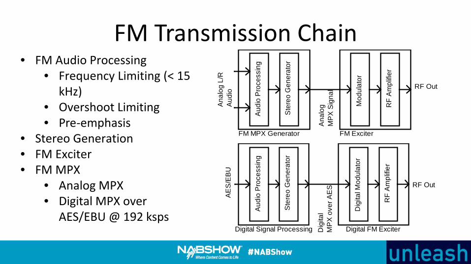
FM Transmission Chain
Aud
io P
roce
ssin
g
Ste
reo
Gen
erat
or
Mod
ulat
or
RF
Am
plifi
er
FM MPX Generator
Ana
log
MP
X S
igna
l
FM Exciter
Ana
log
L/R
Aud
io
RF Out
• FM Audio Processing• Frequency Limiting (< 15
kHz)• Overshoot Limiting• Pre-emphasis
• Stereo Generation• FM Exciter• FM MPX
• Analog MPX• Digital MPX over
AES/EBU @ 192 ksps
Aud
io P
roce
ssin
g
Ste
reo
Gen
erat
or
Dig
ital M
odul
ator
AE
S/E
BU
RF
Am
plifi
er
Digital Signal Processing Dig
ital
MP
X o
ver A
ES
Digital FM Exciter
RF Out

STL Topologies• STL Transport
– Baseband Audio– Analog MPX– Digital MPX
IP Network
Aud
io C
odec
L/R Audio(Analog or AES)
Aud
io C
odec
RDS
SCA 2
SCA 1
L/R Audio(Analog or AES)
RDS
SCA 2
SCA 1
IP Network
MP
X C
odec
MP
X C
odec
Analog MPX(0 to 100 kHz)
Analog MPX(0 to 100 kHz)
IP Network
Aud
io C
odec
AES/EBU192 kHz
Aud
io C
odec
AES/EBU192 kHz

MPX STL Bandwidth• MPX is linear PCM – uncompressed• MPX over AES/EBU is 192 ksps @ 24
bit sampling, one channel – 4.6 Mbps• Analog MPX sampling is 132 to 216
ksps• MPX IP transport uses RTP• IP RTP/UDP header overhead is 40
bytes• Tradeoff between delay and packing
efficiency 0
1
2
3
4
5
6
1 2 3 4
IP B
andw
idth
, Mbp
s
Sampling Rate, ksps
Series1
Series2
Series3
Series4
Series5
Series6

• Benefits of FM MPX over IP vs Audio over IP• Enables baseband equipment (audio processor, stereo generator, RDS
generator) to be located at the studio side• Reduces CapEx when distributing the same signal to multiple transmit sites• Simplifies operation for FM SFN
• However – MPX requires higher STL capacity than audio only transport• Audio is amiable to lossy compression – AAC, MPEG, opus, etc
FM MPX over IP
STL IP Network
Main Audio,RDS,SCA
FM MPX
FM MPX
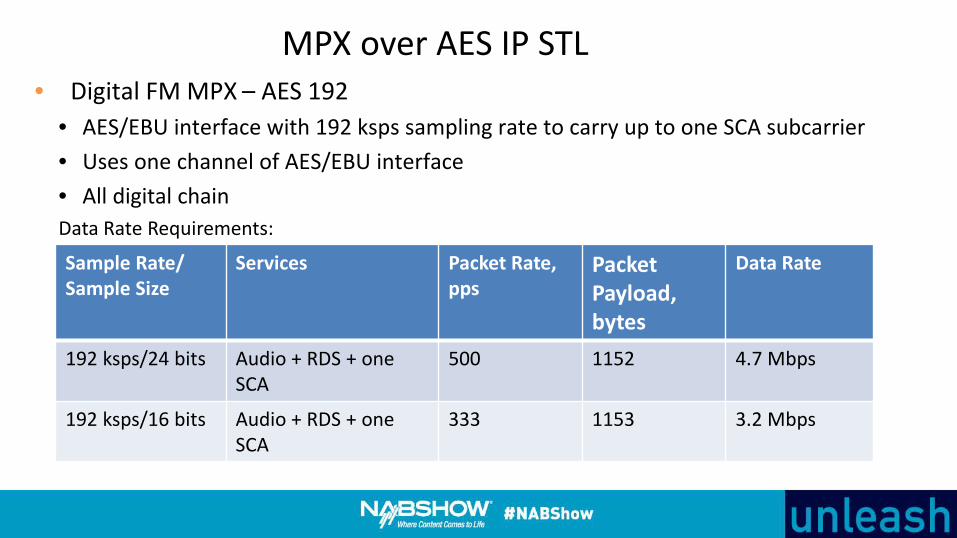
• Digital FM MPX – AES 192• AES/EBU interface with 192 ksps sampling rate to carry up to one SCA subcarrier• Uses one channel of AES/EBU interface• All digital chainData Rate Requirements:
MPX over AES IP STL
Sample Rate/Sample Size
Services Packet Rate,pps
PacketPayload, bytes
Data Rate
192 ksps/24 bits Audio + RDS + one SCA
500 1152 4.7 Mbps
192 ksps/16 bits Audio + RDS + oneSCA
333 1153 3.2 Mbps

• Analog MPX• Flexible sample rate configuration based on FM MPX components to transport• Reduced data rate to carry audio + RDS vs MPX over AES @ 192 ksps• Flexible sample sizes: 16, 20 and 24 bits• Compatibility with existing infrastructure
Analog MPX over IP STL
Sample Rate
Services Packet Rate Range, pps
Data Rate Range
132 ksps Audio + RDS 200 - 333 2.2 – 3.2 Mbps
162 ksps Audio + RDS + SCA 1 333 - 500 2.7 – 4.2 Mbps
216 ksps Audio + RDS + SCA 1 + SCA 2 500 3.6 – 5.4 Mbps
Data Rate Requirements:

IP NetworkADC DACAntialiasingLPF
Analog MPX(0 to 100 kHz)
Clock
LPFAnalog MPX(0 to 100 kHz)
Clock
PCM Datato IPPackets
IP Packetsto PCMData
Analog MPX Codec STL
Studio Site Transmitter Site

• Band from 0 to 53 kHz contains stereo audio• Left: 2L = (L+R) + (L-R)• Right: 2R = (L+R) – (L-R)• Gain flatness of 0.05 dB across 0 to 53 kHz for >50 dB stereo
separation• Linear phase response
Analog MPX Codec Requirements

Linear Phase • Linear phase = constant group
delay
• Use FIR filters for linear phase• Use over-sampling at ADC to
minimize effect non-linear phase response analog filters
• Use interpolation at DAC to minimize effect non-linear phase response analog filter

Butterworth Filter Bode Plot• Flat gain response in the passband• Non linear phase response –
Moderate phase distortion

Example of ADC Characteristics

MPX STL Timing• Ideally…
– Analog MPX – DAC clock is same as ADC clock– MPX over AES – AES/EBU clock at transmitter is same
AES/EBU clock at the studio• In AES/EBU, clock is embedded with data• MPX over AES across the WAN – tight coupling of data/clock is
lost

GPS Based Timing• Precise common timing at
geographically disperse locations
• GPS based receivers with 1 PPS and 10 MHz output
• GPS timing delivery using IEEE 1588 or PTP
• Low phase “noise”, low jitter clock reference
• Generate AES/EBU or ADC/DAC clock using PLL

Timing Recovery• If no common timing reference,
then timing recovery from the RTP stream must be used
• Use RTP packet as time reference• Loose coupling of data/clock• High jitter and phase noise
• In FM, 19 kHz pilot tone tolerance is +/-100 PPM
• In AES/EBU - 1:1 ratio between clock and data
• In RTP – 1:10,000 ratio between clock and data

Phase Lock Loop• Loop stability• Loop filter response < reference
frequency response

Timing Recovery• RTP jitter buffer• Timing recovery algorithm• Adjust DAC clock to keep
constant jitter buffer fill levelFull
Full
FreqDeviationCommandHost
Processor
IPPackets
Jitter Buffer
Maximum Fill Level
Queue SizeOverrun Limit
Minimum Fill Level
Buffer Fill Level
Underrun Limit
MPX Packet to PCM Data
Empty
Empty
Empty
Empty
Full
Full
Full
Full
D/A Sample RateClock
PCM DataSamples D/A
Converter
ProgrammableFrequencyGenerator
IP Network
Analog MPX
Full

Single Frequency Simulcasting
MP
X C
odec
GPS
Mod
ulat
or
RF
Am
plifi
er
MP
X S
igna
l
FM Exciter
MP
X C
odec
Mod
ulat
or
RF
Am
plifi
er
MP
X S
igna
l
FM Exciter
IP Network
MP
X C
odec
MPXSignal
• RF single frequency simulcasting uses multiple, geographically disperse RF transmitters operating on the same carrier frequency
• In simulcast, baseband signal undergoes a precision delay process
• MPX advantage vs audio only transport over STL
• In MPX all components are equally delayed

• Causes of IP packet loss: route flapping, transmission errors, congestion
• Unmanaged vs. managed network services• In audio - packet loss concealment methods: frequency
interpolation, replaying previous frame• In MPX – no standardized concealment methods• For MPX, use correction techniques for packet loss mitigation
IP Packet Loss

Packet Loss Effects• Audio compression algorithms keep
spectral information – fill in missing data segment from previous data –error concealment
• MPX codec method is PCM coding –no spectral information is computed
• MPX codec – no error concealment

IP Packet Loss• Random vs. Burst Packet Loss• Random Losses
• Uncorrelated• Appear to be spread out
Random Loss
Burst Loss

• FEC packets are generated from a matrix of RTP data packets• Both RTP data and FEC packets are sent to the receiver• FEC attempts recovery of lost data packets at the receiver• Effectiveness of recovery depends on type of packet loss
RTP Forward Error Correction

FEC Matrix

FEC Correction for Random Loss
0
0.2
0.4
0.6
0.8
1
1.2
1.4
1 2 3 4 5 6 7 8 9 10 11 12 13 14
EPL,
%
Network Loss, %
4x6
4x4
3x3
2x2

28
Single Network Packet Protection100
100 101
101
Time Delay
102 FEC 103Stream 1
Stream 2
104
Private/ISP
• For burst loss, packet level FEC with interleaving – adds delay• Or, add redundant streams in a group with programmable time delay. Very effective for burst packet
losses which are typically seen on public ISP connections• Time delay value based on network analytics

29
Multiple Network Packet Protection100
100 101
101
Time Delay
102 FEC 103Stream 1
Stream 2
104
WAN 1
100 101 102 FEC 103Stream 3 104
WAN 2
• Network diversity• Grouped streams sent across diverse network paths• Scalable protection per network based on capacity• “Hitless” operation with packet and network losses

30
Summary• High bandwidth IP connections is an enabler for MPX transport• MPX STL - advantage of centralization at studio and simulcasting• Two methods of MPX – MPX over AES and analog MPX• Analog MPX with DSP signal processing can enable high quality
transport• MPX STL timing – common timing or timing recovery• For high quality MPX STL, IP packet loss must be mitigated
• FEC• Redundant streaming• Network diversity

Thank You