
Distortions in Large Aluminum Forgings: Current Situation ...
14
HAL Id: hal-02454596 https://hal.archives-ouvertes.fr/hal-02454596 Submitted on 24 Jan 2020 HAL is a multi-disciplinary open access archive for the deposit and dissemination of sci- entific research documents, whether they are pub- lished or not. The documents may come from teaching and research institutions in France or abroad, or from public or private research centers. L’archive ouverte pluridisciplinaire HAL, est destinée au dépôt et à la diffusion de documents scientifiques de niveau recherche, publiés ou non, émanant des établissements d’enseignement et de recherche français ou étrangers, des laboratoires publics ou privés. Distortions in Large Aluminum Forgings: Current Situation and Simulation Challenges Ramiro Mena, Stéphane Guinard, Jose Aguado, Antonio Huerta To cite this version: Ramiro Mena, Stéphane Guinard, Jose Aguado, Antonio Huerta. Distortions in Large Aluminum Forgings: Current Situation and Simulation Challenges. Computation and Big Data for Transport, In press. hal-02454596
Transcript of Distortions in Large Aluminum Forgings: Current Situation ...

HAL Id: hal-02454596https://hal.archives-ouvertes.fr/hal-02454596
Submitted on 24 Jan 2020
HAL is a multi-disciplinary open accessarchive for the deposit and dissemination of sci-entific research documents, whether they are pub-lished or not. The documents may come fromteaching and research institutions in France orabroad, or from public or private research centers.
L’archive ouverte pluridisciplinaire HAL, estdestinée au dépôt et à la diffusion de documentsscientifiques de niveau recherche, publiés ou non,émanant des établissements d’enseignement et derecherche français ou étrangers, des laboratoirespublics ou privés.
Distortions in Large Aluminum Forgings: CurrentSituation and Simulation Challenges
Ramiro Mena, Stéphane Guinard, Jose Aguado, Antonio Huerta
To cite this version:Ramiro Mena, Stéphane Guinard, Jose Aguado, Antonio Huerta. Distortions in Large AluminumForgings: Current Situation and Simulation Challenges. Computation and Big Data for Transport,In press. �hal-02454596�

Distortions in Large Aluminum Forgings:Current Situation and Simulation Challenges
Ramiro Mena1,2,3,a), Stephane Guinard1, Jose V. Aguado2, and AntonioHuerta3
1Airbus SAS, France2Institut de Calcul Intensif ICI-HPC at Ecole Centrale de Nantes, France
3Laboratori de Calcul Numeric (LaCaN). Departament de Matematica Aplicada III.E.T.S. de Ingenieros de Caminos, Canales y Puertos, Universitat Politecnica de
Catalunya, Spaina)Corresponding author: [email protected]
Abstract. Distortions after machining of large aluminum forgings area recurrent problem for the aeronautical industry. These deviations fromdesign geometry are caused by the presence of residual stresses, whichare developed along the manufacturing chain. To solve this problem, a se-ries of post-machining operations called reshaping are required. Despitereshaping manages to restore the correct geometry, it is highly manualand time-consuming, therefore, there is a need at an industrial level touse numerical simulation to study reshaping. The present document de-scribes the problem of distortion, the operations required to mitigatethese geometrical defects and the challenges associated to simulate re-shaping.
Keywords: Distortions, Residual Stresses, Reshaping, Simulation
1 Introduction
Large and thick-walled aluminum forgings are widely used in the aeronauticalindustry. The key material properties as a great strength-to-weight ratio andgood formability in combination with the manufacturing process allow produc-ing complex shapes in an economical way [14]. Additionally, when comparedto other metal working processes (e.g extensive machining, welding or casting),improved material properties as grain size and orientation are obtained [19].However, aluminum forgings show important distortions after machining due tothe presence of residual stresses which are a consequence of the non-homogeneousplastic strains developed along the manufacturing chain, especially after the heattreatment of quenching [15, 22].
Such distortions are variable in nature, but the industrial process incorpo-rates a robust post-machining stage called reshaping. Particularly, skilled boil-ermakers operate a sequence of mechanical loadings on the non-conforming partand re-establish its nominal geometry while obeying guidelines imposed by stressoffices - which guarantees the produced part has still mechanical characteristics

2 CM3 (Computation and Big Data in Transport)
compatible with its operational role -. An example of the structural parts sub-jected to reshaping are the cruciform beams, located at the wing-box in anaircraft and highlighted in red in Figure 1. On the other hand, reshaping is ahighly manual and collaborative process as multiple operators are involved torepair one single part. At the same time, the process fully depends on the ex-perience of the boilermakers and repairing each structural part in a tailor-mademanner is time-consuming. Therefore, there is a strong demand from the in-dustry to derive operational assistance from capabilities offered by numericalsimulation tools [25].
Focus on distortion mitigation via reshaping, numerical simulations may offerhuge margins for improvements such as operational assistance to boilermakersand related gains in time-cycle (optimized reshaping sequence, optimized param-eters for each elementary reshaping operation), improved knowledge of actualpart and related gains in safety (monitoring of actual plastic strains). However,some research efforts are required in order to migrate from the actual heuristicrepairing method to a simulation-assisted operation, as reshaping simulationspresent challenges to be solved as the elevated computational cost of each sim-ulation or the use of static data of traditional Finite Element Analysis (FEA),to name a few.
This report describes the distortions on aluminum forgings, the operationsrequired to solve this problem and the challenges associated with deploying nu-merical simulations at workshop level and actually help operators. The docu-ment is structured as follows: Section 2 provides an overview of distortions as anopen problem for the aeronautical industry. Then, the relation between residualstresses, distortions, and reshaping are explained in Section 3. Next, the differ-ent reshaping operations are described in detail in Section 4 and the challengesand perspectives to simulate reshaping are reviewed in Section 5. Finally, theobtained conclusions are presented.
2 Distortion in the aeronautical industry: an openproblem
To the best of our knowledge, the problem of distortions in the aeronauticalindustry was first reported during World War II, when some difficulties wereexperienced with extrusions used for aircraft spars parts [12]. Then, due to thetechnology transfer performed after the war, the use of large forgings for lightmetals alloys (i.e magnesium and aluminum) was potentiated with governmentalinitiatives as the Air Force Heavy Press Program in the United States, whichallowed the construction of forgings up to 50k tons capacity1 [2]. Thanks to thisnew range of tools, the unitization2 of structural parts was feasible and acted asa driving force for the development of bigger aircraft with important manufac-turing costs savings [3, 27]. On the other hand, as the forgings grew in size and
1 Nowadays, the biggest forging has a capacity of 80k ton and is located in China [10].2 Action to replace composite structures to single components

CM3 (Computation and Big Data in Transport) 3
Fig. 1. Example of aluminum forgings subjected to distortion: cruciform of the A320wingbox (depicted in red)
with them their cross sections and wall thickness, the range of residual stressesdeveloped after quenching experienced an increment too, so as the research in-terest to predict the residual stresses and any future distortion after machining[13, 21].
At an industrial level, different attempts have been made to minimize distor-tion along the manufacturing chain of heat-treated aluminum alloys components.In North America, the MAI (Metals Affordability Initiative) program [3, 15]and in Europe, the COMPACT (A COncurrent approach to Manufacturing in-duced Part distortion in Aerospace ComponenTs) project [22, 25, 26], focusedon the understanding of residual stress and part distortion. However, both initia-tives efforts were concentrated on the upstream manufacturing processes, suchas quenching, stress relief, ageing, and machining, letting reshaping unattendedand as a byproduct. Theoretically, if distortion is controlled or minimized, thenreshaping is unnecessary. Unfortunately, a part with minimized distortions isonly achieved in exceptional cases [17]. Therefore, we can state that distortionis an open problem for the industry during the last 80 years.
3 Residual Stresses, Distortion and Reshaping
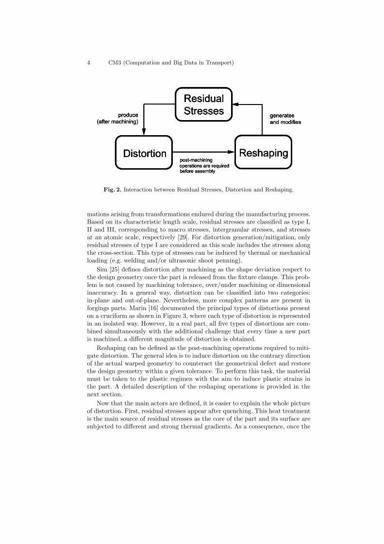
In the distortion mitigation problem, there are three main actors: residual stresses,distortion, and reshaping. They can be considered as the source, the problem,and the current solution, respectively. At the same time, they are interconnectedand interact between them, as represented in Figure 2. In the following section,a definition for each actor is provided.
Residual stresses refer to any stress distribution, which is present in a solid inthe absence of an external load or thermal gradient [23]. In a material, the resid-ual stress distribution is a direct consequence of non-homogeneous plastic defor-
4 CM3 (Computation and Big Data in Transport)
Fig. 2. Interaction between Residual Stresses, Distortion and Reshaping.
mations arising from transformations endured during the manufacturing process.Based on its characteristic length scale, residual stresses are classified as type I,II and III, corresponding to macro stresses, intergranular stresses, and stressesat an atomic scale, respectively [29]. For distortion generation/mitigation, onlyresidual stresses of type I are considered as this scale includes the stresses alongthe cross-section. This type of stresses can be induced by thermal or mechanicalloading (e.g. welding and/or ultrasonic shoot penning).
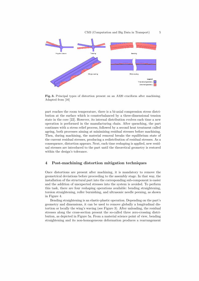
Sim [25] defines distortion after machining as the shape deviation respect tothe design geometry once the part is released from the fixture clamps. This prob-lem is not caused by machining tolerance, over/under machining or dimensionalinaccuracy. In a general way, distortion can be classified into two categories:in-plane and out-of-plane. Nevertheless, more complex patterns are present inforgings parts. Marin [16] documented the principal types of distortions presenton a cruciform as shown in Figure 3, where each type of distortion is representedin an isolated way. However, in a real part, all five types of distortions are com-bined simultaneously with the additional challenge that every time a new partis machined, a different magnitude of distortion is obtained.
Reshaping can be defined as the post-machining operations required to miti-gate distortion. The general idea is to induce distortion on the contrary directionof the actual warped geometry to counteract the geometrical defect and restorethe design geometry within a given tolerance. To perform this task, the materialmust be taken to the plastic regimen with the aim to induce plastic strains inthe part. A detailed description of the reshaping operations is provided in thenext section.
Now that the main actors are defined, it is easier to explain the whole pictureof distortion. First, residual stresses appear after quenching. This heat treatmentis the main source of residual stresses as the core of the part and its surface aresubjected to different and strong thermal gradients. As a consequence, once the
CM3 (Computation and Big Data in Transport) 5
Fig. 3. Principal types of distortion present on an A320 cruciform after machining.Adapted from [16]
part reaches the room temperature, there is a bi-axial compression stress distri-bution at the surface which is counterbalanced by a three-dimensional tensionstate in the core [22]. However, its internal distribution evolves each time a newoperation is performed in the manufacturing chain. After quenching, the partcontinues with a stress relief process, followed by a second heat treatment calledageing, both processes aiming at minimizing residual stresses before machining.Then, during machining, the material removal breaks the equilibrium state ofthe current residual stresses, producing a redistribution of residual stresses. As aconsequence, distortion appears. Next, each time reshaping is applied, new resid-ual stresses are introduced to the part until the theoretical geometry is restoredwithin the design’s tolerance.
4 Post-machining distortion mitigation techniques
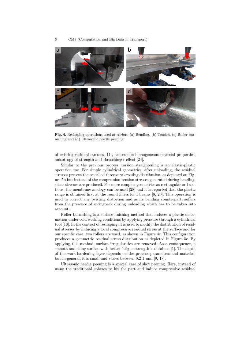
Once distortions are present after machining, it is mandatory to remove thegeometrical deviations before proceeding to the assembly stage. In that way, theinstallation of the structural part into the corresponding sub-component is easierand the addition of unexpected stresses into the system is avoided. To performthis task, there are four reshaping operations available: bending straightening,torsion straightening, roller burnishing, and ultrasonic needle peening, as shownin Figure 4.
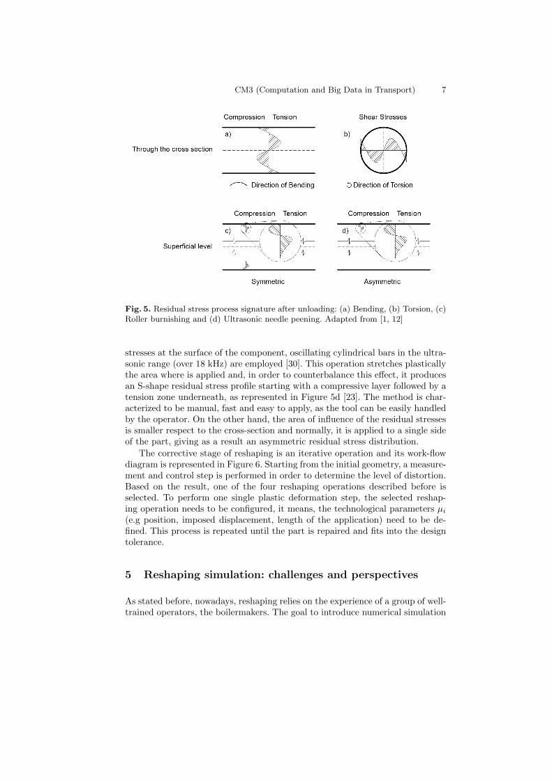
Bending straightening is an elastic-plastic operation. Depending on the part’sgeometry and dimensions, it can be used to remove globally a longitudinal dis-tortion or locally the wing’s waving (see Figure 3). After unloading, the residualstresses along the cross-section present the so-called three zero-crossing distri-bution, as depicted in Figure 5a. From a material science point of view, bendingstraightening and its non-homogeneous deformation produces a rearrangement
6 CM3 (Computation and Big Data in Transport)
Fig. 4. Reshaping operations used at Airbus: (a) Bending, (b) Torsion, (c) Roller bur-nishing and (d) Ultrasonic needle peening.
of existing residual stresses [11], causes non-homogeneous material properties,anisotropy of strength and Bauschinger effect [24].
Similar to the previous process, torsion straightening is an elastic-plasticoperation too. For simple cylindrical geometries, after unloading, the residualstresses present the so-called three zero-crossing distribution, as depicted on Fig-ure 5b but instead of the compression-tension stresses generated during bending,shear stresses are produced. For more complex geometries as rectangular or I sec-tions, the membrane analogy can be used [28] and it is reported that the plasticrange is obtained first at the round fillets for I beams [8, 20]. This operation isused to correct any twisting distortion and as its bending counterpart, suffersfrom the presence of springback during unloading which has to be taken intoaccount.
Roller burnishing is a surface finishing method that induces a plastic defor-mation under cold working conditions by applying pressure through a cylindricaltool [18]. In the context of reshaping, it is used to modify the distribution of resid-ual stresses by inducing a local compressive residual stress at the surface and forour specific case, two rollers are used, as shown in Figure 4c. This configurationproduces a symmetric residual stress distribution as depicted in Figure 5c. Byapplying this method, surface irregularities are removed. As a consequence, asmooth and shiny surface with better fatigue strength is obtained [1]. The depthof the work-hardening layer depends on the process parameters and material,but in general, it is small and varies between 0.2-1 mm [9, 18].
Ultrasonic needle peening is a special case of shot peening. Here, instead ofusing the traditional spheres to hit the part and induce compressive residual
CM3 (Computation and Big Data in Transport) 7
Fig. 5. Residual stress process signature after unloading: (a) Bending, (b) Torsion, (c)Roller burnishing and (d) Ultrasonic needle peening. Adapted from [1, 12]
stresses at the surface of the component, oscillating cylindrical bars in the ultra-sonic range (over 18 kHz) are employed [30]. This operation stretches plasticallythe area where is applied and, in order to counterbalance this effect, it producesan S-shape residual stress profile starting with a compressive layer followed by atension zone underneath, as represented in Figure 5d [23]. The method is char-acterized to be manual, fast and easy to apply, as the tool can be easily handledby the operator. On the other hand, the area of influence of the residual stressesis smaller respect to the cross-section and normally, it is applied to a single sideof the part, giving as a result an asymmetric residual stress distribution.
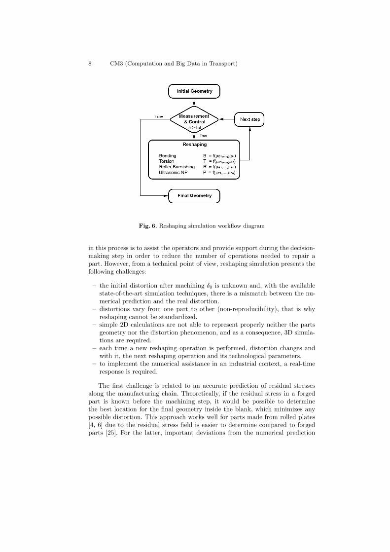
The corrective stage of reshaping is an iterative operation and its work-flowdiagram is represented in Figure 6. Starting from the initial geometry, a measure-ment and control step is performed in order to determine the level of distortion.Based on the result, one of the four reshaping operations described before isselected. To perform one single plastic deformation step, the selected reshap-ing operation needs to be configured, it means, the technological parameters µi
(e.g position, imposed displacement, length of the application) need to be de-fined. This process is repeated until the part is repaired and fits into the designtolerance.
5 Reshaping simulation: challenges and perspectives
As stated before, nowadays, reshaping relies on the experience of a group of well-trained operators, the boilermakers. The goal to introduce numerical simulation
8 CM3 (Computation and Big Data in Transport)
Fig. 6. Reshaping simulation workflow diagram
in this process is to assist the operators and provide support during the decision-making step in order to reduce the number of operations needed to repair apart. However, from a technical point of view, reshaping simulation presents thefollowing challenges:
– the initial distortion after machining δ0 is unknown and, with the availablestate-of-the-art simulation techniques, there is a mismatch between the nu-merical prediction and the real distortion.
– distortions vary from one part to other (non-reproducibility), that is whyreshaping cannot be standardized.
– simple 2D calculations are not able to represent properly neither the partsgeometry nor the distortion phenomenon, and as a consequence, 3D simula-tions are required.
– each time a new reshaping operation is performed, distortion changes andwith it, the next reshaping operation and its technological parameters.
– to implement the numerical assistance in an industrial context, a real-timeresponse is required.
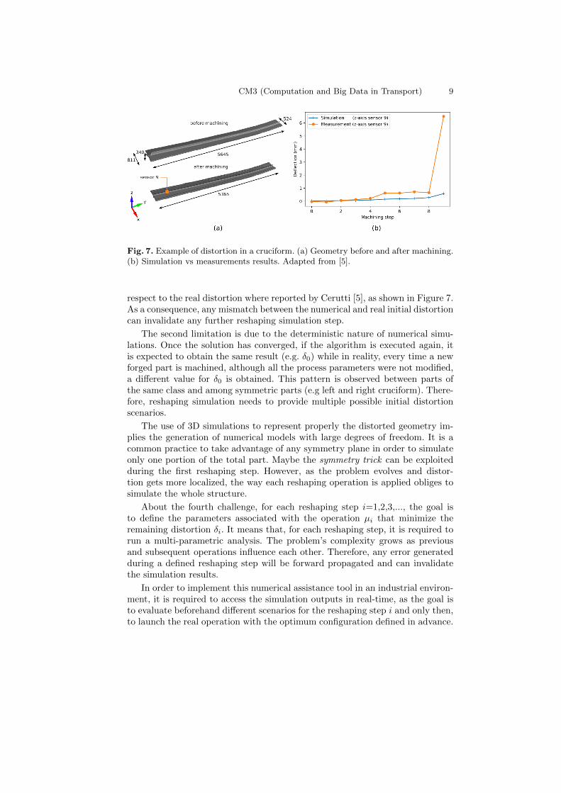
The first challenge is related to an accurate prediction of residual stressesalong the manufacturing chain. Theoretically, if the residual stress in a forgedpart is known before the machining step, it would be possible to determinethe best location for the final geometry inside the blank, which minimizes anypossible distortion. This approach works well for parts made from rolled plates[4, 6] due to the residual stress field is easier to determine compared to forgedparts [25]. For the latter, important deviations from the numerical prediction
CM3 (Computation and Big Data in Transport) 9
Fig. 7. Example of distortion in a cruciform. (a) Geometry before and after machining.(b) Simulation vs measurements results. Adapted from [5].
respect to the real distortion where reported by Cerutti [5], as shown in Figure 7.As a consequence, any mismatch between the numerical and real initial distortioncan invalidate any further reshaping simulation step.
The second limitation is due to the deterministic nature of numerical simu-lations. Once the solution has converged, if the algorithm is executed again, itis expected to obtain the same result (e.g. δ0) while in reality, every time a newforged part is machined, although all the process parameters were not modified,a different value for δ0 is obtained. This pattern is observed between parts ofthe same class and among symmetric parts (e.g left and right cruciform). There-fore, reshaping simulation needs to provide multiple possible initial distortionscenarios.
The use of 3D simulations to represent properly the distorted geometry im-plies the generation of numerical models with large degrees of freedom. It is acommon practice to take advantage of any symmetry plane in order to simulateonly one portion of the total part. Maybe the symmetry trick can be exploitedduring the first reshaping step. However, as the problem evolves and distor-tion gets more localized, the way each reshaping operation is applied obliges tosimulate the whole structure.
About the fourth challenge, for each reshaping step i=1,2,3,..., the goal isto define the parameters associated with the operation µi that minimize theremaining distortion δi. It means that, for each reshaping step, it is required torun a multi-parametric analysis. The problem’s complexity grows as previousand subsequent operations influence each other. Therefore, any error generatedduring a defined reshaping step will be forward propagated and can invalidatethe simulation results.
In order to implement this numerical assistance tool in an industrial environ-ment, it is required to access the simulation outputs in real-time, as the goal isto evaluate beforehand different scenarios for the reshaping step i and only then,to launch the real operation with the optimum configuration defined in advance.

10 CM3 (Computation and Big Data in Transport)
Under the described scenarios, the requirement of multiple reshaping simula-tions together with adaptive modeling and a real-time response suggests launch-ing a multi-parametric analysis under a Model Order Reduction (MOR) frame-work. The idea for this approach is to produce a low-dimensional but accuratemodel in a cost-effective way which allows exploring beforehand the input spaceto construct a solution dictionary, known as computational vademecum [7].
6 Conclusions
Distortion of large aluminum forgings is an open problem for the aeronauticalindustry. Continuous research efforts are done in order to predict the residualstresses that generate this problem. However, it is important from an opera-tional standpoint to study how to handle distortion once it has appeared. In thisdocument, the required post-machining operations to mitigate distortion hasbeen reviewed together with their associated challenges to simulate them. Atthe moment, reshaping is solved based on the empirical experience acquired fora group of well-trained operators. Now, the goal is to find a way to use advancednumerical simulations tools (e.g adaptive modeling, model order reduction) tostudy reshaping in a virtual environment and evaluate possible scenarios beforelaunching the real operation. The long-term goal is to optimize the process in or-der to minimize the total number of reshaping operations and avoid introducingunnecessary residual stresses to the structural part.
Acknowledgements. This project is part of the Marie Sk lodowska-Curie ITN-ETN AdMoRe funded by the European Union Horizon 2020 research and inno-vation program with grant number 675919.
References
[1] Akkurt, A.: Comparison of roller burnishing method with other hole surfacefinishing processes applied on aisi 304 austenitic stainless steel. Journal ofMaterials Engineering and Performance 20(6), 960–968 (2011)
[2] ASME: The Wyman-Gordon 50,000-Ton Forging Press. Tech. rep., TheAmerican Society of Mechanical Engineers (ASME) (1983)
[3] Ball, D., Dubowski, D., Spradlin, T.: Inclusion of Forging Residual Stressesin Large Component Structural Design. In: 2016 USAF Aircraft StructuralIntegrity Program Conference (2016)
[4] Cerutti, X., Mocellin, K., Hassini, S., Blaysat, B., Duc, E.: Methodologyfor aluminium part machining quality improvement considering mechanicalproperties and process conditions. CIRP Journal of Manufacturing Scienceand Technology 18, 18–38 (2016), http://dx.doi.org/10.1016/j.cirpj.2016.07.004
[5] Cerutti, X.: Numerical modelling and mechanical analysis of the machiningof large aeronautical parts: Machining quality improvement. Ph.D. thesis,Ecole Nationale Superieure des Mines de Paris (2014)
[6] Chantzis, D., Van-Der-Veen, S., Zettler, J., Sim, W.M.: An industrialworkflow to minimise part distortion for machining of large monolithiccomponents in aerospace industry. Procedia CIRP 8, 281–286 (2013),http://dx.doi.org/10.1016/j.procir.2013.06.103
[7] Chinesta, F., Leygue, A., Bordeu, F., Aguado, J.V., Cueto, E., Gonzalez, D.,Alfaro, I., Ammar, A., Huerta, A.: PGD-Based Computational Vademecumfor Efficient Design, Optimization and Control. Archives of ComputationalMethods in Engineering 20(1), 31–59 (2013)
[8] Christopherson, D.G.: A Theoretical Investigation of Plastic Torsion in anI-Beam. The Aeronautical Journal 44(353), 425–432 (1940)
[9] Coules, H.E., Horne, G.C., Kabra, S., Colegrove, P., Smith, D.J.: Three-dimensional mapping of the residual stress field in a locally-rolled aluminiumalloy specimen. Journal of Manufacturing Processes 26, 240–251 (2017),http://dx.doi.org/10.1016/j.jmapro.2017.02.010
[10] Du, J., Deng, Q., Dong, J., Xie, X., Wang, Z., Zhao, C., Chen, G., Xie,W., Luo, T., Wang, X., Zhang, Y.: Recent Progess of Manufacturing Tech-nologies on C&W Superalloys in China. In: Ott, E., Banik, A., Liu, X.,Dempster, I., Heck, K., Andersson, J., Groh, J., Gabb, T., Helmink, R.,Wusatowska-Sarnek, A. (eds.) 8th International Symposium on Superalloy718 and Derivatives. pp. 33–46. TMS (The Minerals, Metals & MaterialsSociety) (2014)
[11] Ellermann, A., Scholtes, B.: Residual stress states as a result of bendingand straightening processes of steels in different heat treatment conditions.International Journal of Materials Research 103(1), 57–65 (2012)

12 CM3 (Computation and Big Data in Transport)
[12] Forrest, G.: Internal or Residual Stresses in Wrought Aluminium Alloys andtheir Structural Significance. Journal of the Royal Aeronautical Society pp.261–276 (1954)
[13] Jeanmart, P., Bouvaist, J.: Finite element calculation and measurement ofthermal stresses in quenched plates of high-strength 7075 aluminium alloy.Materials Science and Technology 1(October), 765–769 (1985)
[14] Kalpakjian, S., Steven, S.: Manufacturing Processes for Engineering Mate-rials. 7th edn. (2014)
[15] Ma, K., Goetz, R., Srivatsa, S.K.: Modeling of Residual Stress and Machin-ing Distortion in Aerospace Components. In: Furrer, D., Semiatin, S. (eds.)Metals Process Simulation, pp. 386–407. ASM International (2010)
[16] Marin, G.: Calcul et optimisation des structures mecaniques. Ph.D. thesis,Universite Technologique Compiegne (2000)
[17] Mitze, M.: Straightening heat-treated components. Journal of Heat Treat-ment and Materials 65, 110–117 (2010)
[18] Murthy, R.L., Kotiveerachari, B.: Burnishing of metallic surfaces - a review.Precision Engineering 3, 172–179 (1981)
[19] Narahari Prasad, S., Rambabu, P., Eswara Prasad, N.: Processing ofAerospace Metals and Alloys: Part 2 - Secondary Processing. In: Prasad, N.,Eswara, Wanhill, R. (eds.) Aerospace Materials and Material Technologies,vol. 2, pp. 199–228. Springer Singapore (2017), https://link.springer.com/content/pdf/10.1007%2F978-981-10-2134-3.pdf
[20] Pi, Y.L., Trahair, N.S.: Inelastic Torsion of Steel I-Beams. Journal of Struc-tural Engineering 121(4), 609–620 (1995)
[21] Robinson, J.S., Tanner, D.A., Truman, C.E.: 50th anniversary article: Theorigin and management of residual stress in heat-treatable aluminium alloys.Strain 50(3), 185–207 (2014)
[22] Robinson, J., Hossain, S., Truman, C., Paradowska, A., Hughes, D., Wim-pory, R., Fox, M.: Residual stress in 7449 aluminium alloy forgings. Mate-rials Science and Engineering: A 527(10-11), 2603–2612 (2009)
[23] Schijve, J.: Residual Stress. In: Fatigue of Structures and Materials, pp.89–104 (2009)
[24] Schott, C., Ellermann, A., Zinn, W., Scholtes, B.: Consequences of bendstraightening processes on residual stresses and strength of quenched andtempered steels. HTM - Journal of Heat Treatment and Materials 71(2),75–82 (2016)
[25] Sim, W.: Challenges of residual stress and part distortion in the civil air-frame industry. In: 2nd International Conference on Distortion Engineering.pp. 87–94 (2008)
[26] Sim, W.: Residual Stress Engineering in Manufacture of Aerospace Struc-tural Parts. 3rd International Conference on Distorsions Engineering pp.187–194 (2011)
[27] Smith, C., Crowther, J.: The Production of Large Forgings in AluminiumAlloys. Journal of the Royal Aeronautical Society 59(537), 604–612 (1955)
[28] Timoshenko, S.: Strength of Materials: Part II Advanced Theory and Prob-lems. D.Van Nostran Company, Inc., 2nd edn. (1940)

CM3 (Computation and Big Data in Transport) 13
[29] Withers, P., Bhadeshia, H.: Residual stress. Part 1 Measurement tech-niques. Materials Science and Technology 17(4), 355–365 (2010)
[30] Yin, F., Rakita, M., Hu, S., Han, Q.: Overview of ultrasonic shot peening.Surface Engineering 33(9), 651–666 (2017)


