
Legal challenges in reviewing application for final disposal of spent fuel Tomas Löfgren.

P O S I V A O Y
F I - 2 7 1 6 0 O L K I L U O T O , F I N L A N D
P h o n e ( 0 2 ) 8 3 7 2 3 1 ( n a t . ) , ( + 3 5 8 - 2 - ) 8 3 7 2 3 1 ( i n t . )
F a x ( 0 2 ) 8 3 7 2 3 7 0 9 ( n a t . ) , ( + 3 5 8 - 2 - ) 8 3 7 2 3 7 0 9 ( i n t . )
Disposal Canister for Spent Nuclear Fuel –Design Report
Ju ly 2005
POSIVA 2005 -02
He ikk i Ra iko
POSIVA 2005-02
Ju ly 2005
POSIVA OY
F IN -27160 OLK ILUOTO, F INLAND
Phone (02 ) 8372 31 (na t . ) , ( +358 -2 - ) 8372 31 ( i n t . )
Fax (02 ) 8372 3709 (na t . ) , ( +358 -2 - ) 8372 3709 ( i n t . )
He ikk i Ra iko
VTT P rocesses
Disposal Canister for Spent Nuclear Fuel –Design Report

ISBN 951-652 -134 -7ISSN 1239-3096
The conc lus ions and v i ewpo in ts p resen ted i n the r epo r t a r e
those o f au tho r ( s ) and do no t necessa r i l y co inc ide
wi th those o f Pos i va .
Tekijä(t) – Author(s)
Heikki Raiko, VTT Processes
Toimeksiantaja(t) – Commissioned by Posiva Oy
Nimeke – Title
DISPOSAL CANISTER FOR SPENT NUCLEAR FUEL - DESIGN REPORT
Tiivistelmä – Abstract
The report provides a summary of the design of the canister for final disposal of Finnish spent nuclear fuel. The canister structure consists of a cylindrical massive nodular graphite cast iron insert covered by a 50 mm thick copper overlay. The canister has three versions, one for each reactor type in Finland. The fuel is sealed into the canisters in whole fuel assemblies including the possible flow channel outside the bundle. The capacity of the canister is 12 assemblies of BWR or VVER 440 fuel and 4 assemblies of EPR fuel. The canister shall be tight with a high probability for at least 100 000 years. The good and long lasting tightness requires:
• good initial tightness that is achieved by high quality requirements and extensive quality control,
• good corrosion resistance, which is obtained by the overpack of oxygen-free copper
and • mechanical strength of the canister, that is ensured by analyses; the following loads are
considered: hydrostatic ground water pressure, even and uneven swelling pressure of bentonite, thermal effects, and elevated hydrostatic pressure during glaciation. The allowed stresses and strains are set in such a way that reasonable engineering safety factors are obtained in all assessed design base loading cases.
The canister shall limit the radiation dose rate outside the canister to minimise the radiolysis of the water in the vicinity of the canister. Moreover, the canister insert shall keep the fuel assemblies in a sub-critical configuration even if the void in the canister is filled with water due to postulated leakage. The design basis of the canister is set, the performed analyses are summarised and the results are assessed and discussed in the report.
Avainsanat - Keywords
spent fuel disposal canister, disposal canister design
ISBN ISBN 951-652-134-7
ISSN ISSN 1239-3096
Sivumäärä – Number of pages 61
Kieli – Language English
Posiva-raportti – Posiva Report Posiva Oy FI-27160 OLKILUOTO, FINLAND Puh. 02-8372 (31) – Int. Tel. +358 2 8372 (31)
Raportin tunnus – Report code
POSIVA 2005-02 Julkaisuaika – Date
July 2005

Tekijä(t) – Author(s) Heikki Raiko, VTT Processes
Toimeksiantaja(t) – Commissioned by Posiva Oy
Nimeke – Title
YDINPOLTTOAINEEN LOPPUSIJOITUSKAPSELI - SUUNNITTELURAPORTTI
Tiivistelmä – Abstract
Raportissa esitetään yhteenveto suomalaisen käytetyn ydinpolttoaineen loppusijoituskapselin suunnittelusta ja mitoitusanalyyseistä. Kapselin rakenne muodostuu lieriön muotoisesta massiivi-sesta sisärakenteesta, joka on valmistettu pallografiittiraudasta ja 50 mm:n paksuisesta kuparivai-pasta. Kapselista on kolme erilaista versiota, yksi kutakin suomalaista reaktorityyppiä varten. Polttoaineniput sijoitetaan kokonaisina kapseliin mukaan lukien niihin mahdollisesti kuuluvat virtauskanavat. Kapselin eri versioihin voidaan sijoittaa enintään 12 BWR polttoainenippua, 12 VVER 440 polttoainenippua tai 4 EPR nippua. Kapselin tulee säilyä tiiviinä suurella todennäköisyydellä vähintään 100 000 vuotta. Hyvä ja pit-kään säilyvä tiiviys edellyttävät:
• hyvää tiiviyttä alun perin; tämä saavutetaan valmistuksen korkeilla laatuvaatimuksilla ja laajoilla tarkastuksilla,
• hyvää korroosionkestävyyttä, joka saavutetaan käyttämällä hapetonta kuparia kapselin
vaipan materiaalina, • riittävää mekaanista lujuutta, joka on varmistettu analyysein; kuormitusolettamukset
sisältävät seuraavat ilmiöt: pohjaveden hydrostaattinen paine, bentoniitin tasainen tai epätasainen paisuntapaine, lämpövaikutukset ja 3 km paksun jäätikön aiheuttama ylimääräinen hydrostaattinen paine. Sallittavat jännitykset ja venymät on määritelty siten, että kohtuulliset varmuuskertoimet saavutetaan kaikissa mitoituksen perusteena olevissa kuormitustapauksissa.
Kapselin on rajoitettava säteilytaso kapselin pinnalla niin alhaiseksi, ettei se kohtuuttomasti hankaloita kapselin käsittelyä ja siirtoja ja ettei säteily aiheuta merkittävästi radiolyysiä pohjave-dessä. Lisäksi kapselin sisäosien on pidettävä polttoaineniput alikriittisessä geometriassa silloin-kin, kun kapselin tyhjän sisätilan oletetaan täyttyneen vedellä. Tässä yhteenvetoraportissa määritellään mitoitusperusteet, osoitetaan mitoitusvaatimusten täytty-minen ja arvioidaan analyysien tuloksia.
Avainsanat - Keywords käytetyn ydinpolttoaineen loppusijoituskapseli, loppusijoituskapselin suunnittelu ISBN ISBN 951-652-134-7
ISSN ISSN 1239-3096
Sivumäärä – Number of pages 61
Kieli – Language Englanti
Posiva-raportti – Posiva Report Posiva Oy FI-27160 OLKILUOTO, FINLAND Puh. 02-8372 (31) – Int. Tel. +358 2 8372 (31)
Raportin tunnus – Report code
POSIVA 2005-02 Julkaisuaika – Date
Heinäkuu 2005

1
TABLE OF CONTENTS
Page Abstract Tiivistelmä 1 INTRODUCTION.........................................................................................................5 2 BASIC REQUIREMENTS...........................................................................................7 2.1 Spent fuel characteristics.....................................................................................7 2.2 Radiation shielding..............................................................................................9 2.3 Radiation effects on canister materials ...............................................................9 2.4 Corrosion resistance, life time and leak tightness...............................................9 2.5 Dimensional constraints ................................................................................... 10 2.6 Manufacturing tolerances................................................................................. 11 2.7 Heat loads and allowable temperatures............................................................ 12 2.8 Mechanical design load ................................................................................... 12 2.9 Allowable stresses and strains and required safety factors.............................. 15 2.10 Safety classification.......................................................................................... 16 3 MATERIAL SELECTION AND SPECIFICATION OF PROPERTIES ................ 17 3.1 Specification of manufacturing materials ........................................................ 17 3.2 Quality controls for the materials manufacture ............................................... 19 4 CANISTER DESCRIPTION..................................................................................... 21 4.1 General description and dimensions of the canister ........................................ 21 4.2 Insert variations for BWR, VVER 440, and EPR fuel .................................... 24 5 ENCAPSULATION................................................................................................... 27 5.1 Encapsulation process ...................................................................................... 27 5.2 Canister handling operations............................................................................ 27 5.3 Opening and unloading of the canister ............................................................ 27 6 MECHANICAL AND THERMAL-MECHANICAL DIMENSIONING............... 29 6.1 Strength analysis of the insert .......................................................................... 29 6.2 Flat cover and bottom dimensioning................................................................ 35 6.3 Screw and gasket of the flat lid ........................................................................ 36 6.4 Copper overpack and the lifting shoulder........................................................ 37 6.5 Operation temperature...................................................................................... 39 6.6 Cooling properties of the canister .................................................................... 39 6.7 Thermal stresses and deformations.................................................................. 39 6.8 Creep strains caused by shrinking in cooling period ....................................... 42 6.9 Canister behaviour in accident conditions ....................................................... 43

2
7 RADIATION SHIELDING ....................................................................................... 45 8 CRITICALITY SAFETY........................................................................................... 47 9 MANUFACTURING PROCEDURE....................................................................... 49 9.1 Pre-fabrication of the canister .......................................................................... 49 9.2 Installation tolerances....................................................................................... 49 9.3 Quality controls for the pre-fabrication............................................................ 50 9.4 Sealing weld of the canister lid ........................................................................ 50 9.5 Sealing weld quality control............................................................................. 52 9.6 Repair procedures............................................................................................. 53 10 SUMMARY............................................................................................................... 55 REFERENCES .................................................................................................................... 57
3
PREFACE The report is prepared by VTT Processes for Posiva Oy on contract. The project manager of encapsulation technology in Posiva is Mrs. Tiina Jalonen. Special thanks are addressed to colleagues from VTT Processes, Dr. Kari Ikonen and Mr. Markku Anttila, who have prepared and documented the analyses of strength, criticality safety and radiation shielding of the canister in referenced source reports.

4
5
1 INTRODUCTION The report constitutes a summary of the research and development work made for the de-sign and dimensioning of the canister for spent nuclear fuel disposal. The basic require-ments for dimensioning are given, the design is introduced, and the manufacturing proc-esses and technology are described and assessed in the report. The mechanical strength of the canister in various loading conditions is analysed. In addition, the corrosion, thermal, radiation shielding and criticality analyses of the canister are summarised and discussed. The specifications of quality and integrity requirements of the manufacturing materials are also discussed and preliminary requirements for the manufacture are given. The canister construction type introduced here is a copper canister with a cast insert, which is designed for nuclear fuel disposal in a deep repository in the crystalline bedrock. Three canister versions are dimensioned: one for BWR fuel, second for VVER 440 type PWR fuel and third for EPR reactor fuel. The copper canister with a cast insert consists of two major components: the massive nodular graphite cast iron insert and the corrosion resistant overpack of oxygen-free cop-per. The insert provides mechanical strength and radiation shielding, and keeps the fuel assemblies in a fixed configuration. During the final sealing of the lid of the copper over-pack, the insert acts as a gas tight vessel keeping the fuel assemblies with the inert gas at-mosphere in the void space isolated from the EB-welding process made in vacuum. Dur-ing the transfer and handling operations the canister is gripped from the shoulder at the top lid corner with a mechanical gripping device. The canisters presented here contain 12 positions for VVER 440 or BWR fuel assemblies and 4 positions for EPR fuel assemblies. The amount of uranium in each canister ranges from 1.4 to 2.2 tons depending on the fuel type. The total weight of the canister including fuel assemblies is 18.6, 24.3 and 29.1 tons, respectively. The outside diameter of the canis-ter for all types is 1.050 m and the total length is about 3.6, 4.8 or 5.25 m, respectively.

6
7
2 BASIC REQUIREMENTS The basic design requirements of the canister for nuclear waste disposal are as follows:
• The canister must not be penetrated by corrosion during the first 100 000 years after disposal in anticipated repository condition
• The fuel from existing OL1-2 and Lo1-2 units to be disposed of has an average burnup of 37 - 39 MWd/kgU, the estimated maximum burnup per fuel assembly in future is 50 MWd/kgU. The average burnup of the future OL3-unit spent fuel is estimated to be about 47-48 MWd/kgU. The minimum cooling time of a single fuel assembly is 20 years.
• The maximum dose rate on the outer surface of the canister shall be less than 1 Gy/h to minimise the radiolysis of water or altering the bentonite buffer out-side the canister.
• The canisters shall be sub-critical even if the void inside the canister is filled with water. The sub-criticality is to be checked for a single canister and a set of canis-ters in the buffer storage of the encapsulation plant and in the disposal holes of the repository.
• The canister surface temperature in repository condition shall not exceed +100 oC to guarantee the non-boiling condition of the brine as far as in atmospheric pres-sure and the chemical stability of the surrounding bentonite in longer perspective.
• The maximum canister decay power is limited in reference case to 1700 W for the BWR canister in safety analysis. This leads to comparable power of 1370 W for VVER 440 canister and of 1830 W power for EPR canister.
• The canister shall be designed to withstand the load caused by disposal at a depth of 400 to 700 m, which entails an evenly distributed load of 7 MPa hydrostatic pressure from groundwater and 7 MPa pressure from swelling of bentonite.
• The canister strength shall be demonstrated also in non-symmetric cases of ben-tonite swelling without groundwater pressure and in a case of additional hydro-static load of 30 MPa caused by 3 kilometres of ice during a glaciation.
• The strength of the copper overpack is to be checked for handling and operational loads during the disposal process.
• Canister shall not harm the function of other barriers in the repository. • Retrievability of the waste canisters shall be maintained to provide for such
development of technology that makes it a preferred option. 2.1 Spent fuel characteristics The spent fuel characteristics for Swedish Asea Atom BWR (nowadays Westinghouse Electric Sweden), Russian VVER 440, and French EPR reactor are given in Table 1. The length of fuel rods and assemblies may grow in the reactor some 10 to 25 mm depending on the burnup.

8
TABLE 1. Fuel characteristics for BWR, VVER 440 and EPR fuel. Minor fuel details may vary depending on fuel manufacturer but main data are constant.
FUEL TYPE Asea-Atom
BWR VVER 440 PWR
EPR PWR
Assembly sectional configuration square hexagonal square Length of assembly (m) 4.127 3.217 4.865** Sectional dimension (mm) 139 * 144 214 Number of rods per assembly 63 - 100 126 265 Mass of uranium (kg) 172 - 180 120 - 126 530 - 533 Total assembly mass (kg) 292 - 331 210-214 785 Flow channel dimension (mm) 139 (square) 144 (hexagonal) No channel Total length with flow channel (m) 4.398 3.217 4.865** Anticipated maximum average burnup of a fuel assembly (MWd/kgU)
50 50 50
Estimated average burnup of all the fuel (MWd/kgU)
38 - 39 39 - 40 46 - 47
Typical enrichment U-235 (%) 3.3 - 3.8 3.6 - 4.0 3.6 - 4.2 Minimum cooling time of a single bundle (years)
20 20 20
Minimum average cooling time with average burnup (years)
43.7 31.5 56.5
Allowable average decay heat at disposal (full canisters) (W/tU)
806 950 862
*) The top end handle of the BWR fuel assembly has some more extensive details, max dimension 151 mm. **) The fuel element has springs on the top tie-plate that extends the total length with some tens of millime-
tres. Geometric details of the fuel element are to be confirmed later. Control rods are not included in the fuel elements that are to be disposed.
The BWR fuel assemblies will be inserted with flow channels into the canister. The canis-ter is dimensioned for 8x8-, 9x9- and 10x10-type fuel assemblies with the standard flow channel. The VVER 440 fuel assembly is an integral structure with the hexagonal flow channel. The channel makes the assembly much longer than the fuel rods. The EPR fuel assembly is of 17x17-24 -type with no flow channel. The top end plate has some axial springs that lengthen the maximum dimension (height) of the assembly. Con-trol rods are not included in the fuel elements that are planned to be disposed. In radiation shielding analysis the maximum average burnup of a single fuel assembly is assumed to be 50 MWd/kgU. Modern BWR fuel assemblies have the so-called axial re-flectors made of natural uranium at their both ends. This results locally in much higher
9
than the average burnups at the axial midpoint of the assemblies. Therefore, a local burnup of 60 MWd/kgU is used in radiation shielding calculations. The minimum cooling time after removal from the reactor for a single fuel bundle is 20 years. This minimum value is used in radiation dose and shielding calculations. The average cooling time of the assemblies in each canister is, however, much longer to keep the maximum temperature of the canister surface in allowable limits. Thermal opti-misation of the final repository is made in (Ikonen 2003a) and (Ikonen 2003b). The reports give the details of disposal strategy and allowed heat loads for canisters. 2.2 Radiation shielding To prevent any significant radiolysis in groundwater or altering the bentonite buffer at the outer surface of the canister in the repository, the surface dose rate should be below 1 Gy/h, (Werme 1998). From the point of view of radiation shielding, the main concern is the dimensioning of the shields in the encapsulation facility and transport system. The dimensioning of the radiation shields of the capsulation facility and transport system are based on the actual calculated dose rate. The calculated dose rates on the outer surface of the canisters are presented in Chapter 7. The resulting dose rate is clearly lower than the maximum allowable 1 Gy/h. This result gives also a design base for the radiation shielding calculations for the encapsulation plant and for dose evaluation during the plant operation. 2.3 Radiation effects on canister materials High energy radiation can damage the crystalline structure of the metals causing thus change in dimensions and physical properties. An investigation made by (Guinan 2001) shows that with actual dose rates and spectrum no detectable damages or changes are caused in the canister materials throughout the full service life of canisters with good margin. By comparing with experiments in the literature, a conclusion was drawn that the magnitude of any physical property changes (e. g. yield stress, creep rates, enhanced solute segregation, dimensional changes, or embrittlement) resulting from exposure to neutron and gamma radiation over the service life of the canister will be negligible. Therefore, radiation effects on materials will not impose any additional constraints on canister design. 2.4 Corrosion resistance, life time and leak tightness The outside shell made of oxygen-free copper is designed for long life corrosion protec-tion, leak tightness and to bear the loads during transportation and handling operations. The canister design aims at providing with a high probability a corrosion lifetime of at least 100 000 years in the repository environment. The canister shall not be penetrated by corrosion in order to prevent water from entering the canister during the first 100 000 years after deposition. The lifetime of the overpack may be limited by corrosion or mechanical failure. The stability of oxygen-free copper in repository environment is widely studied in (Aaltonen & Varis 1993), (Ahonen & Vieno

10
1994), (Ahonen 1995), (Saario & al. 1999), (Arilahti & al. 2000), (Milodowski & al. 2000), (Fennell & al. 2001), (Taxén 2002a), (Taxén 2002b), (King & al. 2002), (King 2002), (Bojinov & Mäkelä 2003). The estimated lifetime (time to perforation) of a 15 mm thick flawless copper overpack in typical groundwater environment is much higher than 100 000 years, (Werme 1998). For conservative mechanical, manufacturing and corrosion resistance reasons the thick-ness of the intact oxygen-free copper overpack is conservatively selected to be at least 30 mm. Designed nominal wall thickness of the copper overpack is about 50 mm. The excess dimension between 50 and 30 mm is reserved for manufacturing allowances (tolerances) and for postulated flaws in the base material or welds. The oxidation of the copper canister outer surface during the short storage time, at maxi-mum a couple of months, in the air atmosphere of the buffer store of the encapsulation plant is negligible in spite of the maximum elevated temperature of about +100 oC. A thin copper oxide layer will be formed on the canister surface. After disposal and before water saturation it is possible that the canister can be in contact with air and dry bentonite at a temperature of max. +100 oC. Also in this type of condition the amount of oxidation is estimated in (Werme 1998) to be negligible. The insert structure is designed to be leak tight only during the sealing process of the cop-per overpack. The seal welding of the copper lid is planned to be made by electron-beam welding in vacuum. In the post-closure safety analysis (Vieno & Nordman 1999) the insert is not assumed to provide any hindrance for the release of radio-nuclides. The canister insert will be exposed to internal corrosion if the void in the insert is filled with air. The total void of the canister is about 0.61, 0.95 and 0.68 m3 in VVER 440, BWR and EPR type canister inserts with fuel assemblies in each position, respectively. In addi-tion, the water remains in the fuel and the air inside the canister insert may cause nitric acid formation with the assistance of irradiation. The nitric acid increases the risk for stress corrosion cracking (SCC). To avoid the risk, the canister atmosphere is planned to be re-placed by inert gas (helium or argon) during encapsulation process, if the SCC-risk cannot be shown negligible by further investigations. In addition, to minimize the acid formation risk, the fuel bundles are dried in an autoclave before they are installed into canister. The massive insert structure made of nodular graphite cast iron is not prone to creep in disposal temperatures and, thus, the shape and size of the externally pressure loaded insert will remain stable. 2.5 Dimensional constraints The size and shape of the various types of canisters will be kept as close to each other as possible for manufacturing and operational reasons and standardisation. All of the canister types have the same outer diameter and the lid design with the shoulder for the gripping device is identical. This is useful in manufacture and handling operations and minimises the need of special tools and equipment. The length of canister is, however, different for

11
different type fuel. Accordingly, the dead weight of the canisters varies. The holes for the assemblies in the canister insert have some clearance to assure the installation of fuel as-semblies without friction drag or risk of jamming when using the fuel handling machine in the encapsulation station. The maximum capacity of the canister is limited by the cooling properties of the bentonite and rock surrounding the canister in the repository. The canister structure is dimensioned according to the required strength, radiation shielding and sub-criticality properties, tightness and lifetime. Sub-criticality must be guaranteed even if the canister void is filled with water. The outside dimension and the lid shoulder for lifting device is similar to that of the Swed-ish SKB canister design. 2.6 Manufacturing tolerances Manufacturing tolerances mean in this context dimensional (geometric) tolerances, align-ment, roundness and surface roughness. The geometric design has been made so that the planned properties of the canister can be achieved with reasonable workshop tolerances that do not require any unusual or complex machining tools or processes. The openings in the insert are designed so wide, that the alignment and dimensions achieved directly in the casting process are sufficient. Especially the square shaped open-ings for BWR or EPR fuel assemblies can not easily be machined, the surface of the open-ings is only cleaned by blasting. The nominal width of the square opening is, at least, 20 mm more than the nominal width of the fuel assemblies. This tolerance allows reasonable inaccuracies in the shape of the openings caused by the casting process. In addition, the spent fuel bundles, specially the BWR type, can be in some cases curved. The highest measured deviation in straightness in full length of a BWR flow channel is 9 mm at TVO. The actual width and straightness requirement of the BWR insert openings is controlled after casting with a straight jig with a sectional dimension of 154 mm. These tolerances are calculated to allow free installation of even slightly curved fuel elements. The machining tolerance of ±0.5 mm in diameter in cylindrical products with a typical di-ameter of 1 m and length of 4 to 5 m is achieved typically with a ”good manufacturing practise”. The nominal inside diameter of the copper overpack and the outside diameter of the insert has a nominal difference of 2 mm, which corresponds to a nominal 1 mm radial gap between the cylinders. An actual difference of 3 mm in the diameters is acceptable according to creep analysis by (Knuutila 2001a). This allowance will guarantee a freely sliding installation of the insert into the copper overpack. A slight pre-heating of the cop-per overpack will help, in case there will arise difficulties in the installation. For example, the copper cylinder diameter is expanded by 1.6 mm with pre-heating of 100 oC. Eccentricity of the insert has a remarkable effect on the collapse load of the canister ac-cording to the canister strength analyses (Ikonen 2005). Eccentricity means here the inac-curacy in the polar symmetry of the openings for the fuel bundles in the insert. As a com-promise between the strength requirements and the foundry practise a maximum limit of 5 mm is set for the insert eccentricity after machining. Due to stress concentration, the outer corner radius of the square steel tubes in the BWR insert is specified to be 15 to 25 mm.

12
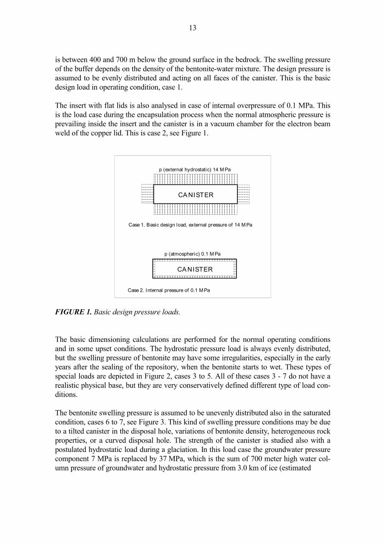
The surface roughness requirement for the weld preparation of electron-beam weld be-tween the copper lid and the cylinder is Ra = 3.2 µm according to (Aalto 1998). All other machined surfaces have the surface requirement Ra = 12.5 µm. 2.7 Heat loads and allowable temperatures The maximum operation temperature at the canister surface in repository condition is lim-ited to be below +100 oC to assure the chemical stability of the highly-compacted ben-tonite in the disposal hole and to avoid the concentration of salt in the vicinity of the canis-ter due to vaporisation of groundwater in the early years after the sealing of repository. The highest design temperature of the metal parts of the canister is thus set for the strength analyses to +100 oC. The decay heat generation in canisters will depend on the amount, burnup, operational his-tory and cooling time of the fuel. The initial decay heat load in a canister is limited to 1700 W in reference case (BWR canister). Accordingly the power limit for VVER 440 and EPR canisters are 1370 W and 1830 W, respectively. The thermal conductivity of the copper body of the canister is two orders of magnitude higher than the conductivity of the sur-rounding bentonite and rock in the repository. Therefore the metallic canister surface will be practically at a uniform temperature and the entire thermal gradient will prevail in the bentonite and rock around the canister and in possible air gaps between the material inter-faces. Heat conduction and thermal optimisation in repository are studied and discussed in more detail for KBS-3V type repository in (Ikonen 2003a) and for KBS-3H type in (Iko-nen 2003b). The maximum fuel rod temperature inside the canister is estimated to be about +300 oC. This is calculated assuming radiation heat transfer and conduction through the gas be-tween the fuel rods and the canister insert, when the canister surface temperature is +100 oC. Also the 1 to 1.5 mm gap between the insert and the copper overpack is assumed to act as an isolator. Thermal phenomena inside a canister are more closely discussed in (Rossi et al. 1999) and later in (Rasilainen 2004). Some further investigations are to be done to verify the emissivity of the machined copper surface. Namely, in temperatures close to +100 oC, remarkable share of heat transfer is occurring by radiation over gas filled gaps. Such gaps as this exist between the insert and the copper overpack and between the copper overpack and the bentonite buffer, at least in early phase of disposal. Thus the total thermal conductivity over a gas filled gap is strongly dependent on the surface emissivity of the respective surfaces. 2.8 Mechanical design load The basic mechanical design load for the canister is 14 MPa external pressure in normal condition. The design load consists of 7 MPa hydrostatic pressure (water column of 0.7 km) and a maximum of 7 MPa swelling pressure of bentonite according to (Werme 1998) and (Karnland 1998). The swelling pressure of 7 MPa corresponds to the dry bentonite density of 1590 kg/m3 or density of 2020 kg/m3 at water saturation. Both of the primary dimensioning pressure components are conservative estimates. The planned disposal depth
13
is between 400 and 700 m below the ground surface in the bedrock. The swelling pressure of the buffer depends on the density of the bentonite-water mixture. The design pressure is assumed to be evenly distributed and acting on all faces of the canister. This is the basic design load in operating condition, case 1. The insert with flat lids is also analysed in case of internal overpressure of 0.1 MPa. This is the load case during the encapsulation process when the normal atmospheric pressure is prevailing inside the insert and the canister is in a vacuum chamber for the electron beam weld of the copper lid. This is case 2, see Figure 1.
CA NISTER
CA NISTER
Case 2. Internal pressure of 0.1 M Pa
p (atmospheric) 0.1 M Pa
p (external hydrostatic) 14 M Pa
Case 1. Basic design load, external pressure of 14 M Pa
FIGURE 1. Basic design pressure loads. The basic dimensioning calculations are performed for the normal operating conditions and in some upset conditions. The hydrostatic pressure load is always evenly distributed, but the swelling pressure of bentonite may have some irregularities, especially in the early years after the sealing of the repository, when the bentonite starts to wet. These types of special loads are depicted in Figure 2, cases 3 to 5. All of these cases 3 - 7 do not have a realistic physical base, but they are very conservatively defined different type of load con-ditions. The bentonite swelling pressure is assumed to be unevenly distributed also in the saturated condition, cases 6 to 7, see Figure 3. This kind of swelling pressure conditions may be due to a tilted canister in the disposal hole, variations of bentonite density, heterogeneous rock properties, or a curved disposal hole. The strength of the canister is studied also with a postulated hydrostatic load during a glaciation. In this load case the groundwater pressure component 7 MPa is replaced by 37 MPa, which is the sum of 700 meter high water col-umn pressure of groundwater and hydrostatic pressure from 3.0 km of ice (estimated

14
F i x eden d s
S i m p l esu p p o r t s
F i x edo n e en d
C A N I S T E R
C A N I S T E R
C A N I ST E R
C ase 3 : W et t i n g p h ase, l o c a l ex c en t r i c sw e l l i n g p r essu r e
C ase 4 : W e t t i n g p h ase, l o c a l ex c en t r i c sw e l l i n g p r essu r e
C ase 5 : W et t i n g p h ase , l o c a l ex c en t r i c sw el l i n g p r essu r e
L / 1 0 L / 1 0
L / 2
L / 1 0
p = 7 M P a
p = 7 M P a
p = 7 M P a
L / 1 0
FIGURE 2. Special local swelling loads postulated during wetting phase.
100%100%
80%120%
80%
CA NISTER
80%
80%
80%
100%
100%
p (swel l ing) 100%
p (swel l ing) 100%
Shear load
Case 6. L ocal l y excentric bentoni te swell ing pressure
Case 7: A xisymmetric but variable bentoni te swel l ing pressure
FIGURE 3. Special swelling pressure loads postulated in fully saturated phase. Ground-water hydrostatic pressure can be present simultaneously.

15
density 1 000 kg/m3) floating on the groundwater. In this extreme load case (p = 44 MPa, the sum of 700 meter groundwater + 3000 meter ice pressure + 7 MPa swelling pressure of bentonite) the canister insert and overpack is analysed and the postulated load is compared to the calculated collapse load. This is case 8. The integrity of the canister can be damaged due to shear type rock movements if the shear plane happens to intersect the deposition hole and the shear amplitude is large enough. When the bentonite buffer around the canister is 350 mm thick it can be estimated that the shear movements of the rock up to 100 mm can be tolerated without the direct break of the canister (Börgesson et al. 2003). The probability of such occurrence is investigated in (La Pointe & Hermanson 2002). The risk caused by large rock movements, which may occur during the melting phase of a major continental glacier, is minimised by locating the dis-posal gallery outside major fracture zones in the bedrock. (Vieno & Nordman 1999). In addition, the lifting equipment and the shoulder in the copper lid collar are dimensioned for the gravity load of the loaded canister multiplied by the dynamic factor of lifting loads and required safety factor. 2.9 Allowable stresses and strains and required safety factors Design strength and strain The design strength of the material in the basic dimensioning calculation is the yield strength in the design temperature divided by the required safety factor. The minimum yield strength of the manufacturing materials is given in material standards, e.g. in (SFS-EN 1563) and (SFS-EN 10025). The manufacturing tolerance of the gap between the copper overpack and the iron insert has to be limited in such a way that the maximum plastic or creep strain in copper will be less than 5% in case the copper overpack is deformed due to pressure load against the in-sert. Safety factors Safety factor is the ratio of the design strength and the actual allowable general membrane stress intensity. The stress intensity is a reduced stress (a scalar quantity) that is defined in stress analysis standard (SFS 3292) as the difference between the major and minor princi-pal stress component. For pressure vessels made of steel the required safety factor is typi-cally 1.5. For pressure vessels made of nodular cast iron the required safety factor in pres-sure vessel standards is typically 3.5 - 4.5. The disposal canister cannot be directly compared to a pressure vessel due to the fact that pressure vessels are designed for cyclic operation (usually thousands of operation cycles) whereas the disposal canister has only one or a few load cycles. This is why the fatigue control is not relevant. Another requirement, toughness, is not very relevant due to the fact that in the design load case the canister is loaded by external pressure only, which leads to compressive stresses in major parts of the canister. Keeping these facts in mind, the re-

16
quired safety factor in the design load case can be justifiably set for cast iron insert to 2.0. The stress state in the canister is typically compression in all three orthogonal dimen-sions and the risk of elastic or even plastic buckling is eliminated up to very high load by the integral support structure, the bulkheads or separation walls of the insert. For limit load analyses, see (Ikonen 2005). For the steel lids the safety factor is taken as 1.5. That is the required safety factor for hot rolled steel according to the Finnish pressure vessel standard (SFS 2610). The safety factor for the stresses due to handling loads in copper vessel is taken 1.5 to avoid plastic deformation and residual stresses. In addition, the strength of the structure is checked in many postulated upset conditions. These loads are caused by either local irregularities in bentonite swelling or ice age load-ing, which is conservatively assumed to cause an additional hydrostatic pressure by 3 km thick ice floating on groundwater. These load cases are specified in section 2.8, cases 3 to 8, see Figures 2 and 3. The canister is checked not to break or collapse due to these loads. Local plasticity and moderate irreversible deformation is allowed during the postulated upset load conditions in the canister structure, but the leak tightness shall not be lost. Rea-sonable margin against rupture or collapse in all upset load cases shall be verified. 2.10 Safety classification Systems, structures and components important to safety shall be designed, manufactured, installed and operated in such a way that their quality level and the inspections and tests needed to verify their quality level are commensurate with the importance to safety of each item. The national nuclear safety authority STUK has published a guide (YVL-guide 2.1), which sets the principles and criteria of the classification. Another STUK guide (YVL-guide 8.5) tells that the canister shall be classified as an important component from the point of view of long term safety. According to the YVL-guide 2.1 components shall be assigned to safety class 2, if their failure to operate would cause a considerable risk of uncontrolled criticality. On the other hand, components shall be assigned to safety class 3, if their fault or failure would prevent decay heat removal from spent fuel, or cause the dispersal of radioactive material. The ap-pendix of the YVL-guide 2.1 gives an example that the storage racks for fresh and spent fuel are assigned to safety class 2 and the storage of spent fuel and liquid wastes, including pools and tanks, are assigned to safety class 3. From these rules and examples given in the YVL-guide it can be concluded that the canis-ter overpack for nuclear fuel disposal shall be preliminarily classified in safety class 2 and the insert in safety class 3. The reason for higher classification of copper overpack is the extreme high lifetime specified for the tightness of the canister. Leak of water into the can-ister cavities due to penetration of the copper overpack would decrease also the sub-criticality of the fuel configuration in the canister.
17
3 MATERIAL SELECTION AND SPECIFICATION OF PROPERTIES The insert is made of nodular graphite cast iron. The iron quality is selected in such a way that adequate strength is achieved and the ductility of the material is adequate. The pro-posed quality is EN-GJS-400-15U according to the European Standard (SFS-EN 1563). The manufacturing material, nodular cast iron, is selected instead of cast steel or welded steel structure due to its superior manufacturing aspects. The material for the overpack is oxygen-free high conductivity copper (Cu-OF according to the Finnish standard (SFS 2905)) with an addition of 30 to 70 ppm phosphorus. We call this micro alloyed quality in this report ‘Cu-OFP´. The micro-alloying is made to improve the creep strain properties of Cu-OF copper in higher temperature (+200 to +300 oC). Copper is selected as a corrosion protection layer due to its chemical stability. It is a very noble metal, it is available at reasonable cost, and it does not require an oxide film on the surface to withstand the corrosion as many other passive metals like titanium or alumin-ium do. 3.1 Specification of manufacturing materials Iron and steel The insert is made of nodular graphite cast iron. The proposed quality is EN-GJS-400-15U according to the European standard (SFS-EN 1563). The design strength of the EN-GJS-400-15U quality is 240 MPa in room temperature. Minimum ultimate strength is accord-ing to the standard 370 MPa and the guideline value of elongation to fracture 11% for dominant wall thickness of 60 mm thick or more, when measured from specimen made of cast-on bar. Actual elongation to fracture is specified to be on average 7% measured from 6 specimens made of the top part of the insert cast itself. Other relevant physical properties of the nodular graphite iron are: density 7200 kg/m3, Young’s modulus 170 GPa, Pois-son’s ratio 0.28, linear coefficient of thermal expansion 10 to 12⋅10-6 1/ oC according to (SFS-EN 1563) and (SFS 3345). The flat covers of the insert are made of structural steel S355J2G3 defined according to (SFS-EN 10025) or any equivalent quality. All the specified strength and ductility values are shown in Table 2. When making radiation shielding and dose rate calculations, the representative chemical content of the structural component materials is needed. Typical contents (in weight %) of the canister materials are as follows:
• Copper overpack; Cu 100 % • Cast iron insert; Fe 92.8, C 3.2, Mg 0.05, Si 2.15, Mn 0.8, Ni 1.0 % (Werme &
Ericsson 1995) • Steel parts of the insert; Fe 98.3, C 0.2, Mn 1.5 % (SFS-EN 10025).
18
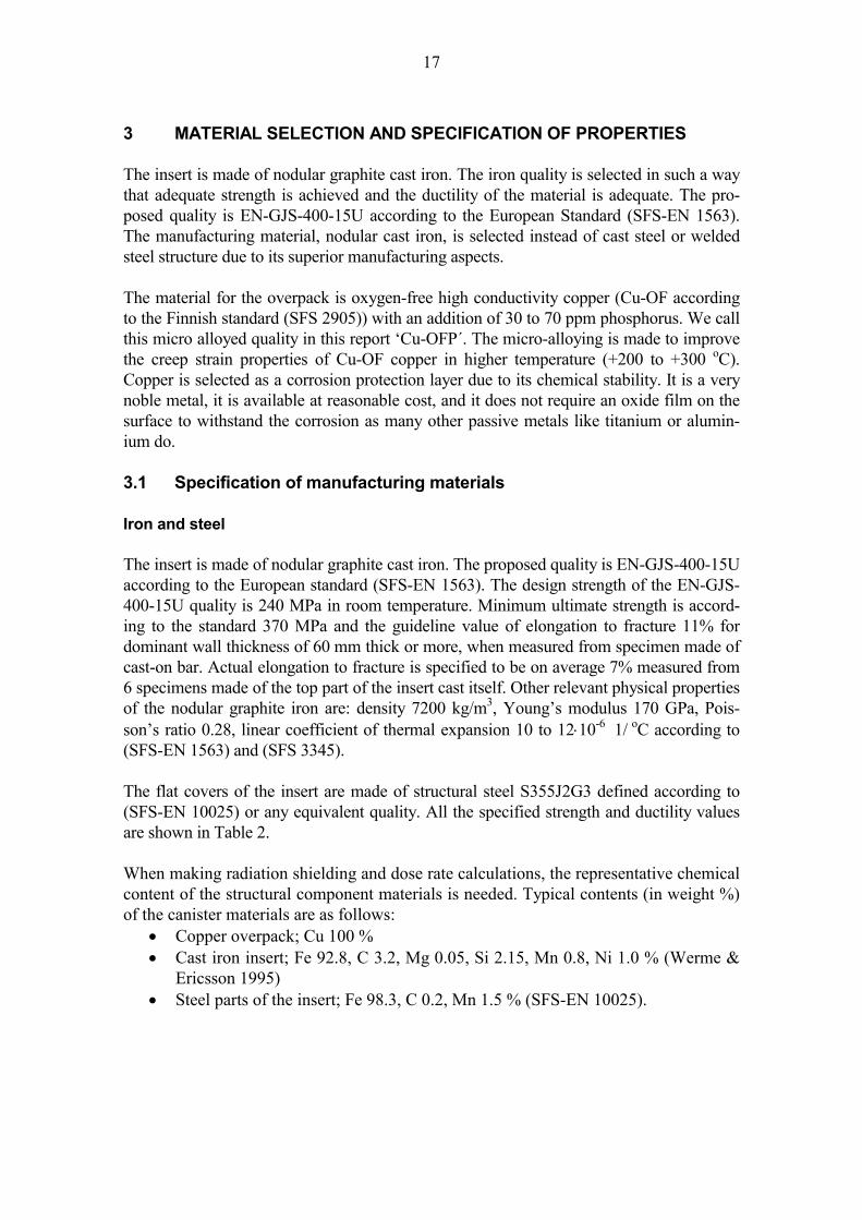
TABLE 2. Minimum specified strength and ductility properties for nodular graphite cast iron EN-GJS-400-15U and structural steel S355J2G3 in room temperature and in design temperature (+100 oC). Respective typical properties for oxygen-free copper are added on the bottom line for comparison. Material quality
Ultimate strength (MPa)
Elongation to fracture (%)
Yield strength in +20 oC (MPa)
Yield strength in +100 oC (MPa)
EN-GJS-400-15U 370 11*) 240 ~230 S355J2G3 490-630 19 335 ~295 Cu-OF 200 50 50 45
*) cast-on bars Copper The yield strength of oxygen-free copper is in annealed condition typically 50 MPa in the room temperature (+20 oC) and about 45 MPa in the design temperature of +100 oC. The elongation (1-axial strain) to fracture (in standardised 1-dimensional tensile tests) is typi-cally 50% according to (Copper and copper alloy data 1968). The specified minimum elongation of hot-worked canister copper is set to 40%. This specification covers the hot worked base material and the welds. The very low speed creep fracture elongation in oxygen-free copper is about 10%. The es-timate is based on results of creep tests made on EB-welded oxygen-free copper and welds (Auerkari & Holmström 1997). The maximum allowable tensile plastic or creep strain in copper material including welds is set in the design analyses, however, conservatively to 5% due to the limited amount of reliable long term creep data of oxygen-free copper mate-rial. The grain size in copper base material shall be less than 360 µm to guarantee the hot-worked condition of the material and a reasonable resolution in ultrasonic testing accord-ing to (Andersson et al. 2004). This grain size 360 µm gives a resolution at ultrasonic testing comparable to X-ray testing of 50 mm thick copper. In copper welds the typical grain size is, however, much larger (Aalto 1998), (Jeskanen & Kauppinen 1997) and (Jeskanen & al. 2001). Typical physical and mechanical properties of copper in the hot-worked conditions are presented in Table 3. Other relevant physical properties for copper are: density 8900 kg/m3, Young’s modulus 118 GPa, Poisson’s ratio 0.345 and linear coefficient of thermal expansion 17⋅10-6 1/oC (Copper and copper alloy data 1968). The material for copper canisters shall fulfil the specification of the grades Cu-OFE or Cu-OF1 with the following additional requirements. The additional material analysis require-ments of oxygen-free copper are presented in Table 4. The oxygen content is limited for EB-weldability, the low sulphur is for tensile strength and ductility and the phosphorus for creep ductility reasons.
19
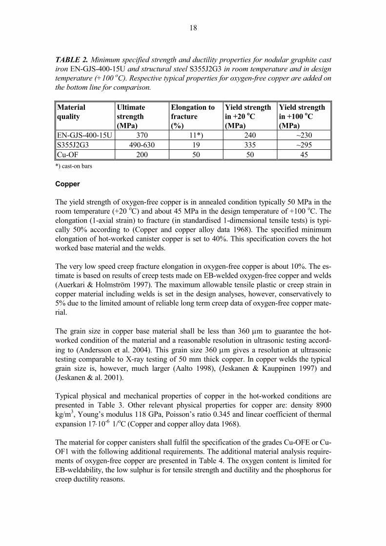
TABLE 3. Typical measured physical and mechanical properties of hot rolled oxygen-free copper (t = 50 mm plates) used in EB-welding tests (Rajainmäki et al. 1995). Copper quality
Ultimate strength (MPa)
Yield strength (MPa)
Elongation to fracture (%)
Grain size (µm)
Electric conductivity (% IACS)
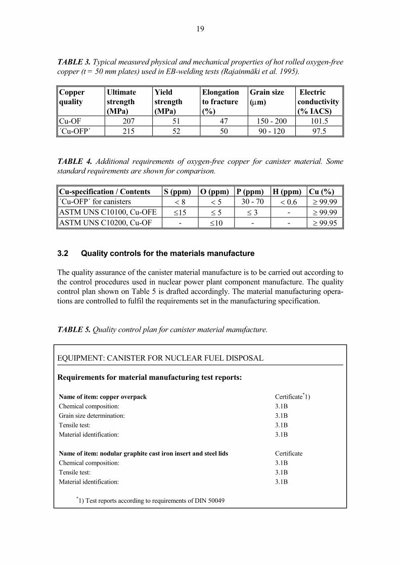
Cu-OF 207 51 47 150 - 200 101.5 ´Cu-OFP´ 215 52 50 90 - 120 97.5 TABLE 4. Additional requirements of oxygen-free copper for canister material. Some standard requirements are shown for comparison. Cu-specification / Contents S (ppm) O (ppm) P (ppm) H (ppm) Cu (%) ´Cu-OFP´ for canisters < 8 < 5 30 - 70 < 0.6 ≥ 99.99 ASTM UNS C10100, Cu-OFE ≤15 ≤ 5 ≤ 3 - ≥ 99.99 ASTM UNS C10200, Cu-OF - ≤10 - - ≥ 99.95 3.2 Quality controls for the materials manufacture The quality assurance of the canister material manufacture is to be carried out according to the control procedures used in nuclear power plant component manufacture. The quality control plan shown on Table 5 is drafted accordingly. The material manufacturing opera-tions are controlled to fulfil the requirements set in the manufacturing specification. TABLE 5. Quality control plan for canister material manufacture. EQUIPMENT: CANISTER FOR NUCLEAR FUEL DISPOSAL Requirements for material manufacturing test reports: Name of item: copper overpack Certificate*1) Chemical composition: 3.1B Grain size determination: 3.1B Tensile test: 3.1B Material identification: 3.1B Name of item: nodular graphite cast iron insert and steel lids Certificate Chemical composition: 3.1B Tensile test: 3.1B Material identification: 3.1B
*1) Test reports according to requirements of DIN 50049

20
21
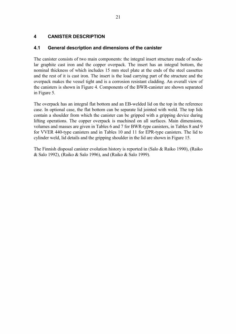
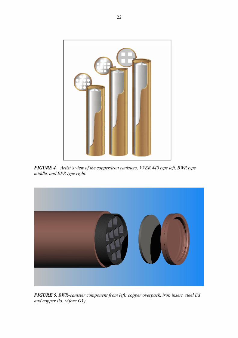
4 CANISTER DESCRIPTION 4.1 General description and dimensions of the canister The canister consists of two main components: the integral insert structure made of nodu-lar graphite cast iron and the copper overpack. The insert has an integral bottom, the nominal thickness of which includes 15 mm steel plate at the ends of the steel cassettes and the rest of it is cast iron. The insert is the load carrying part of the structure and the overpack makes the vessel tight and is a corrosion resistant cladding. An overall view of the canisters is shown in Figure 4. Components of the BWR-canister are shown separated in Figure 5. The overpack has an integral flat bottom and an EB-welded lid on the top in the reference case. In optional case, the flat bottom can be separate lid jointed with weld. The top lids contain a shoulder from which the canister can be gripped with a gripping device during lifting operations. The copper overpack is machined on all surfaces. Main dimensions, volumes and masses are given in Tables 6 and 7 for BWR-type canisters, in Tables 8 and 9 for VVER 440-type canisters and in Tables 10 and 11 for EPR-type canisters. The lid to cylinder weld, lid details and the gripping shoulder in the lid are shown in Figure 15. The Finnish disposal canister evolution history is reported in (Salo & Raiko 1990), (Raiko & Salo 1992), (Raiko & Salo 1996), and (Raiko & Salo 1999).
22
FIGURE 4. Artist’s view of the copper/iron canisters, VVER 440 type left, BWR type middle, and EPR type right.
FIGURE 5. BWR-canister component from left; copper overpack, iron insert, steel lid and copper lid. (Afore OY)
23
TABLE 6. Mass and dimensional data of the BWR canister.
Cast insert
Steel lid Copper cylinder
Copper lid
Fuel assembly
Outside diameter [m] 0.950 0.910 1.050 1.050 Wall thickness [m] 0.050 0.048 0.050 Bottom thickness [m] 0.065 0.050 Free length [m] 4.450 Total length [m] 4.565 4.8 4.398 Material volume [m3] 1.82 0.032 0.78 0.048 0.0347 Density [kg/m3] 7200 7850 8900 8900 8555 Mass [kg] 13100 250 6962 425 300 Total mass [kg] 13100 250 6962 425 3600
TABLE 7. Mass and volume balances of the BWR canister.
Copper Steel or iron
Fuel assemblies
Void space Total
Mass [kg] 7387 13350 3600 - 24337 Volume [m3] 0.83 1.85 0.416 0.95 4.05
TABLE 8. Mass and dimensional data of the VVER 440 canister.
Cast insert
Steel lid Copper cylinder
Copper lid
Fuel assembly
Outside diameter [m] 0.950 0.910 1.050 1.050 Wall thickness [m] 0.050 0.048 0.050 Bottom thickness [m] 0.065 0.050 Free length [m] 3.250 Total length [m] 3.365 3.6 3.217 Material volume [m3] 1.40 0.032 0.60 0.048 0.0262 Density [kg/m3] 7200 7850 8900 8900 8168 Mass [kg] 10100 250 5300 425 214 Total mass [kg] 10100 250 5300 425 2568
TABLE 9. Mass and volume balances of the VVER 440 canister.
Copper Steel or iron
Fuel assemblies
Void space Total
Mass [kg] 5725 10350 2568 - 18643 Volume [m3] 0.65 1.43 0.314 0.61 2.99

24
TABLE 10. Mass and dimensional data of the EPR canister. Some numbers estimated.
Cast insert
Steel lid Copper cylinder
Copper lid
Fuel assembly
Outside diameter [m] 0.950 0.910 1.050 1.050 Wall thickness [m] 0.052 0.048 0.050 Bottom thickness [m] 0.085 0.050 Free length [m] 4.878 Total length [m] 5.015 5.25 4.865 Material volume [m3] 2.46 0.032 0.85 0.048 0.1 Density [kg/m3] 7200 7850 8900 8900 ∼ 8000 Mass [kg] 17735 250 7585 425 775 Total mass [kg] 17735 250 7585 425 3140
TABLE 11. Mass and volume balances of the EPR canister.
Copper Steel or iron
Fuel assemblies
Void space Total
Mass [kg] 8000 18000 3140 - 29140 Volume [m3] 0.90 2.49 0.39 0.68 4.46
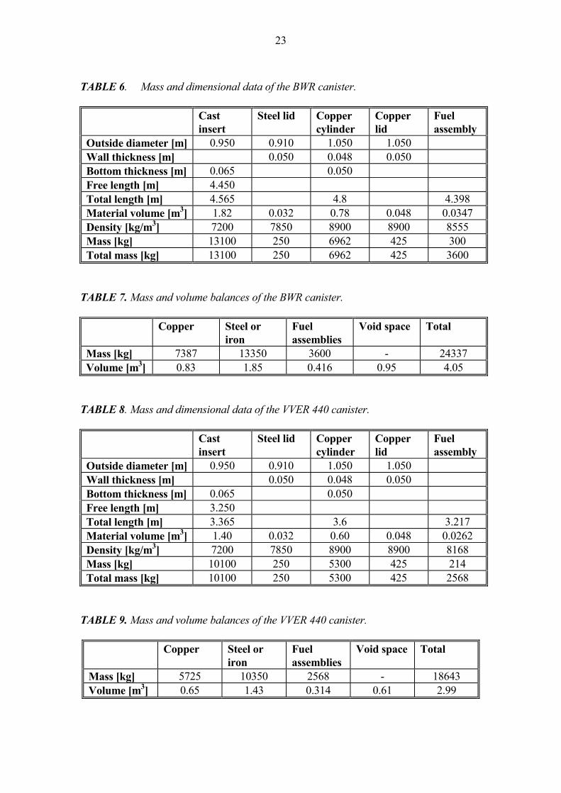
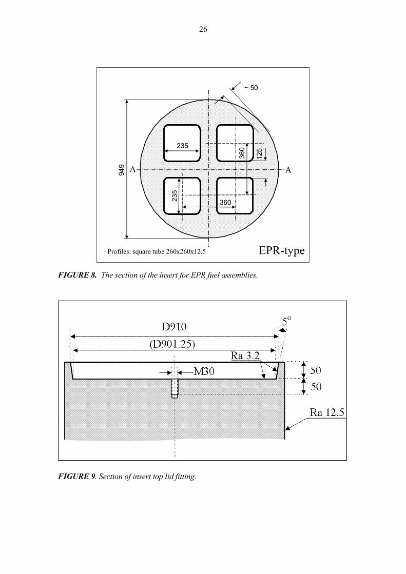
4.2 Insert variations for BWR, VVER 440, and EPR fuel The insert is made of nodular graphite cast iron in one piece. This cast type insert structure was originally introduced by the Swedish Nuclear Fuel and Waste Management Co. (SKB), Sweden, in (Werme & Eriksson 1995). The positions for fuel assemblies are holes, which are dimensioned and formed either for BWR, VVER 440, or EPR fuel assemblies. The inserts have an integral flat bottom of 50 mm cast iron for BWR and VVER 440 type and 70 mm for the EPR type. Bottom thickness is higher in EPR insert because of wider openings. The total bottom thickness is the sum of nominal thickness mentioned above and the steel rack bottom plate thickness of 15 mm. All insert types have loose flat lids made of 50 mm steel plate on top ends. The top lids are fixed centrally with 1 pin screw (size M30) and there is a gasket between the lid edge and the insert body. The gasket is an O-ring made of rubber. The purpose for the gasket is to keep the gases inside the insert during the electron beam welding of the copper lid. The EB-weld is made in vacuum. The sections of the insert types for various fuel assemblies are shown in Figures 6, 7 and 8. The insert lid arrangement is shown in Figure 9.

25
FIGURE 6. The section of the insert for BWR fuel assemblies.
~ 46
36
210
210
949
D174
VVER 440-type
AA
Profiles: round tube 193.7x10
FIGURE 7. The section of the insert for VVER 440 fuel assemblies.
160 160
~ 35
50
210
21094
9
BWR-type
AA
Profiles: square tube 180x180x10
26
FIGURE 8. The section of the insert for EPR fuel assemblies.
FIGURE 9. Section of insert top lid fitting.
~ 50
125
949
360235
360235
EPR-type
A A
Profiles: square tube 260x260x12.5
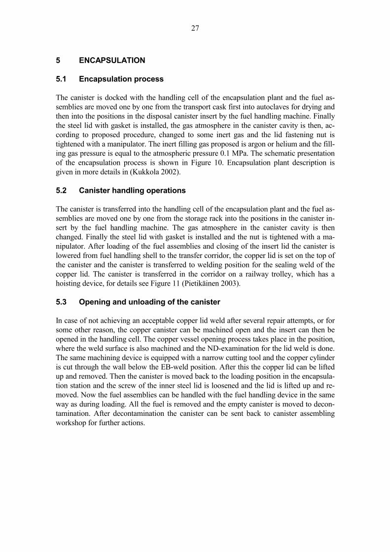
27
5 ENCAPSULATION 5.1 Encapsulation process The canister is docked with the handling cell of the encapsulation plant and the fuel as-semblies are moved one by one from the transport cask first into autoclaves for drying and then into the positions in the disposal canister insert by the fuel handling machine. Finally the steel lid with gasket is installed, the gas atmosphere in the canister cavity is then, ac-cording to proposed procedure, changed to some inert gas and the lid fastening nut is tightened with a manipulator. The inert filling gas proposed is argon or helium and the fill-ing gas pressure is equal to the atmospheric pressure 0.1 MPa. The schematic presentation of the encapsulation process is shown in Figure 10. Encapsulation plant description is given in more details in (Kukkola 2002). 5.2 Canister handling operations The canister is transferred into the handling cell of the encapsulation plant and the fuel as-semblies are moved one by one from the storage rack into the positions in the canister in-sert by the fuel handling machine. The gas atmosphere in the canister cavity is then changed. Finally the steel lid with gasket is installed and the nut is tightened with a ma-nipulator. After loading of the fuel assemblies and closing of the insert lid the canister is lowered from fuel handling shell to the transfer corridor, the copper lid is set on the top of the canister and the canister is transferred to welding position for the sealing weld of the copper lid. The canister is transferred in the corridor on a railway trolley, which has a hoisting device, for details see Figure 11 (Pietikäinen 2003). 5.3 Opening and unloading of the canister In case of not achieving an acceptable copper lid weld after several repair attempts, or for some other reason, the copper canister can be machined open and the insert can then be opened in the handling cell. The copper vessel opening process takes place in the position, where the weld surface is also machined and the ND-examination for the lid weld is done. The same machining device is equipped with a narrow cutting tool and the copper cylinder is cut through the wall below the EB-weld position. After this the copper lid can be lifted up and removed. Then the canister is moved back to the loading position in the encapsula-tion station and the screw of the inner steel lid is loosened and the lid is lifted up and re-moved. Now the fuel assemblies can be handled with the fuel handling device in the same way as during loading. All the fuel is removed and the empty canister is moved to decon-tamination. After decontamination the canister can be sent back to canister assembling workshop for further actions.

28
FIGURE 10. Schematic presentation of the encapsulation plant and process. The lift to transfer the canister from the encapsulation plant to the repository is on the right. In op-tional case of ramp transfer the canister lift is missing. The rooms to the right of the lift are reserved for bentonite buffer preparation and storing (Kukkola 2002).
FIGURE 11. The railway trolley for the canister handling in the encapsulation line of the plant (Pietikäinen 2003).

29
6 MECHANICAL AND THERMAL-MECHANICAL DIMENSIONING The mechanical strength of the canister is checked in load conditions specified in Section 2.8. The cast iron insert structure is checked in design pressure load cases to have a rea-sonable margin (safety factor 2) in general membrane stresses when compared to the mate-rial design strength (yield strength) in the design temperature. Secondly, the structure is checked in postulated upset load conditions (irregular local bentonite swelling loads dur-ing wetting phase, non-symmetric swelling loads in saturated phase, and the extreme hy-drostatic pressure load during glaciation) to have a reasonable margin against rupture fail-ure. In addition, the copper overpack is checked to withstand the lifting and handling device loads during encapsulation, transport and disposal operations. 6.1 Strength analysis of the insert Design pressure loads, cases 1 and 2 The insert is dimensioned in two basic design load cases: 1. external pressure 14 MPa (the sum of 7 MPa pressure of the 700 m groundwater and 7 MPa pressure of the expanding bentonite), and 2. internal pressure 0.1 MPa (during the vacuum of the lid EB-weld). The load cases 1 and 2 are first checked according to the Finnish pressure vessel norm (SFS 2862) and (SFS 2611), respectively. Load case 2 leads to a very low stress in the cyl-inder, less than 1 MPa. In load case 1 the integral structure is conservatively modelled for manual calculation as a cylinder continuously stiffened against unstable buckling. The re-quired minimum wall thickness (s) of the cylinder is calculated according to (SFS 2862) formula (1) as follows:
sp D no=
⋅ ⋅⋅2 0 2σ .
, (1)
where p is the external pressure (14 MPa), Do is the outside diameter of the cylinder (0.950 m), n is the safety factor (2.0), and σ0.2 is the yield strength of the material in the design temperature (230 MPa). The required cylindrical shell wall thickness from the Formula (1) is s = 58 mm. The ac-tual ´equivalent cylinder´ wall thickness is at least 120 mm in all of the canister variants; see Figures 5, 6 and 7. The equivalent wall thickness is defined by summing the load bear-ing section thicknesses in the weakest section of the insert, e.g. the sum of the thickness of the bulkheads and the outer circumference 25 mm + 50 mm + 45 mm for BWR-type in-sert. The measure 25 mm is the half of the 50 mm bulkhead at the centre, 50 mm the bulk-head at half radius and 45 mm the load bearing neck at the outer circumference.
30
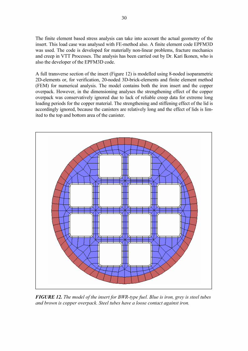
The finite element based stress analysis can take into account the actual geometry of the insert. This load case was analysed with FE-method also. A finite element code EPFM3D was used. The code is developed for materially non-linear problems, fracture mechanics and creep in VTT Processes. The analysis has been carried out by Dr. Kari Ikonen, who is also the developer of the EPFM3D code. A full transverse section of the insert (Figure 12) is modelled using 8-noded isoparametric 2D-elements or, for verification, 20-noded 3D-brick-elements and finite element method (FEM) for numerical analysis. The model contains both the iron insert and the copper overpack. However, in the dimensioning analyses the strengthening effect of the copper overpack was conservatively ignored due to lack of reliable creep data for extreme long loading periods for the copper material. The strengthening and stiffening effect of the lid is accordingly ignored, because the canisters are relatively long and the effect of lids is lim-ited to the top and bottom area of the canister.
FIGURE 12. The model of the insert for BWR-type fuel. Blue is iron, grey is steel tubes and brown is copper overpack. Steel tubes have a loose contact against iron.

31
The finite element mesh used in the strength analysis of the cast insert is shown in Figure 12. The model consists of a 2-dimensional slice of the insert. The model contains several hundreds of isoparametric elements. The finite element model is shown in Figure 13. The external pressure load is modelled to act on the cylindrical outer surface and, in 3D-verification case also on the planar ends of the insert. The axial loading pressure is mod-elled in such a way that the effective resultant force on the transverse metal surface equals to the equivalent force of the external pressure times the surface area of the steel lid. Con-straints are set to eliminate the rigid body motion of the 2D-model and, additionally in the 3D-case, all the transverse sections of the insert are forced to stay coplanar.
FIGURE 13.The finite element mesh of the full transverse section of the insert for BWR-type fuel. Deformations and von Mises stress distribution with design pressure 44 MPa. Eccentricity is 5 mm to upward right direction at angle of 45 degrees. Copper layer is omitted for conservatism. Square steel profiles with loose contact against the cast body are included in the model, because they have a remarkable effect on the collapse load. The corresponding stress analysis is reported in (Ikonen 2005). The numerical stress analysis shows that the stress intensity level in case 1 is very low, in average less than 50

32
MPa, in the circumference and in the bulkheads between the square openings. When as-sessing the stress intensity results of the numerical analyses one should keep in mind that the canister insert is in compressed condition in all the three dimensions simultaneously due to external pressure load. Furthermore, the numerical stress analysis result shows that the stiffening and load bearing effect of the internal bulkheads of the iron insert is very remarkable. Non-symmetric and bending loads, cases 3 to 7 The section properties of the cast insert relevant for bending strength are presented in Ta-ble 12. TABLE 12. Sectional properties of the cast insert for various types of insert.
Sectional area A (m2)
Section modulus W (m3)
Flexural rigidity I (m4)
BWR -type insert 0.4001 0.05635 0.02674 VVER 440 -type insert 0.4230 0.05855 0.02778 EPR -type insert 0.4864 0.06882 0.03266
The maximum bending stress in the insert can be calculated according to the linear beam theory from the bending moment according to formula (2)
σ b
MW
= , (2)
where M is the bending moment in the section, and W is the section modulus. The ultimate loading capacity of a beam in the bending case can be calculated according to formula (3)
M Wu u= ⋅ ⋅σ Φ, (3)
where Mu is the ultimate bending moment capacity, W is the section modulus, σu is ultimate strength (at minimum 370 MPa), and Φ is the rupture factor of the bending beam (1.35 for thick walled cylin-
der). The bending capacity (W/L2) of the BWR-type insert is the lowest of the three insert varia-tions, thus the calculation check is made only with BWR insert dimensional data. Using the above formula for the ultimate bending capacity of a beam we get the ultimate bend-ing capacity of the insert Mu = 370 MPa ⋅ 0.05635 m3 ⋅ 1.35 = 28.15 MNm.

33
The bending effect in load cases 3 to 6 can be calculated from the actual maximum bend-ing moment of the case and the section modulus given in Table 12. The bending stress re-sults are presented in Table 13. The yield stress is exceeded remarkably only in case 5, but even in that case the ultimate bending capacity (at ultimate strength 370 MPa) is only nominally exceeded. The stiffening and load bearing effect of the copper cylinder is con-servatively ignored. The plastic bending capacity of the copper cylinder (calculated with yield strength of 50 MPa of annealed copper) is 1.2 MNm. Taking this into account, the conservatively calculated stress in iron insert is decreased to (21.2-1.2)/21.2*376= 355 MPa that is lower than the ultimate strength. As discussed in chapter 2.8, the load cases 3 to 7 are overly conservative assumptions, because the bentonite is assumed to be able to constrain the canister rigidly. Some numerical analyses have been made for SKB showing that bentonite buffer, as a whole, is behaving in a much more flexible way in this kind of load condition. For more details, see chapter 3.3 of (Jing 2004). TABLE 13. Bending moment and bending stress (according to linear beam theory) in load cases 3 to 6. Legend: L = length of the canister 4.8 m, D = outside diameter of the canister 1.05 m, and p = specified maximum bentonite swelling pressure 7 MPa. The bending capacity (W/L2) of the BWR-type canister is the lowest, thus the calculation check is made with BWR insert dimensional data only.
Load case Maximum bending moment
Maximum bending moment (MNm)
Maximum bending stress (MPa)
3 1/12 ⋅ p ⋅ D ⋅ (4/5 ⋅ L)2 9.0 160 4 1/8 ⋅ p ⋅ D ⋅ (4/5 ⋅ L)2 13.6 241 5 1/2 ⋅ p ⋅ D ⋅ (1/2 ⋅ L)2 21.2 376 6 0.2 ⋅ 1/16 ⋅ p ⋅ D ⋅ L2 2.1 37.3
Load case 7 (see section 2.8, Figure 3) is the only one that possibly causes some other stresses than pure compression to the copper overpack. If we consider the axial force bal-ance (in load case 7) between the ends of the canister, we see that the unbalance must be compensated by axial friction forces between bentonite and copper overpack. The unbal-anced reaction force between the ends in this case is
∆ ∆F pD
= ⋅⋅π 2
4, (4)
where ∆F is the unbalanced axial force, ∆p is the pressure difference (20% of the maximum bentonite swelling
pressure 7 MPa) between the ends, and D is the outside diameter of the canister overpack (1.050 m). We get the unbalanced force ∆F = 1.21 MN. If we conservatively ignore the friction be-tween the copper overpack and the inside insert structure, we can presume that the unbal-
34
anced force is transferred by the copper overpack only. The maximum possible axial stress in copper overpack in this load case is the unbalanced force divided by the sectional area of the copper cylinder. We get the maximum axial stress of 7.8 MPa. This is a very low stress when compared to the copper yield strength (45 MPa) in the design temperature. The unbalanced axial force is, in practice, balanced by the friction between the copper cyl-inder and the iron insert, which causes some shear stresses on the copper cylinder. How-ever, these are one or two orders of magnitude lower than the axial stress and can be thus ignored. Ice load, case 8 The extreme loading condition, case 8, external pressure 44 MPa (hydrostatic pressure of 7 MPa + bentonite swelling pressure of 7 MPa + extra hydrostatic pressure of 30 MPa due to three kilometres of ice) is checked not to cause a collapse failure of the canisters. This load case can be analysed by numerical methods only. The linear-elastic finite ele-ment calculation of the ice load case, load case 8, was made and the stress intensity result is shown in Figure 13. The resulting average stress intensity is less than 150 MPa in the circumference and in the bulkheads of the iron insert and the analysis in (Ikonen 2005) verifies that even in this case the safety factor against global collapse is more than 2 for all three insert variations. Analysis of collapse load In addition and for comparison, the collapse load of the insert was assessed with the same finite element model and program. The extreme load case leads to limited plasticity and large deformation in the insert structure. In addition, in case of square tube openings, the steel tubes tend to be separated from the cast iron body due to weak interface strength be-tween the steel tubes and the cast iron. The material behaviour is modelled in this ultimate case including the post-yield condition. The critical measures in this kind of analysis are the maximum strain and the maximum deformation. The limit load analysis for the canister structure (insert + copper overpack) was made with finite element method using non-linear (elastic-plastic) material modelling and large de-formations. In dimensioning analyses the effect of copper overpack was conservatively omitted. Limit load means the pressure load that starts the plastic collapse of the insert structure. The yielding and strain hardening material behaviour was modelled with bit-by-bit linear stress-strain relation based on the yield (240 MPa at +20 oC) and ultimate strength (370 MPa) and respective typical measured behaviour of the cast material. The load, external pressure, was incrementally increased acting on the model surface. The non-linear analysis was continued in load increments as far as to the point that the structure became unstable due to exceeding large deformations caused by the external load. The stepwise balance iteration was used to put the system converge with all increments. The ratio between load and maximum displacement was very stable until about 90 MPa pressure and after that the

35
displacements started to increase more rapidly. As far as the iteration is converging the strain state is stable and the load carrying capacity is not exceeded. The results show that the pressure load carrying capacity of the cast insert is at least about 90 MPa in case of BWR-type insert and far more with other type inserts. This gives at least a safety factor of two against collapse even in load case 8, ice load of 3 km glacier during glaciation. The FEM-analyses were made with Silicon Graphics workstation. The number of degrees of nodes of the typical 2D-model is about 500, and the number of elements is about 150. The non-linear solution was made in hundreds of load increments and the balance between loads and stresses was iterated during each of the load increments. 6.2 Flat cover and bottom dimensioning The mechanical strength of the flat cover is checked in three (of the eight) relevant load cases: 1. external pressure 14 MPa (7 MPa pressure of the groundwater + 7 MPa pressure
of the expanding bentonite, maximum temperature +100 oC) 2. internal pressure 0.1 MPa (during the vacuum of the lid EB-weld), and 8. external pressure 44 MPa (design loading condition during ice age, canister tem-
perature +20 oC). The flat cover is made of structural steel S355J2G3 according to (SFS-EN 10025). The yield strength of the steel is 335 MPa in room temperature and 295 MPa in the design temperature +100 oC. Flat covers are dimensioned according to the Finnish standard (SFS 2615). The safety factor used for design load of structural steel is 1.5. The required cover plate thickness is calculated according to the formula (5):
s C z a p n y≥ ⋅ ⋅ ⋅ ⋅ / σ (5)
where C is constant depending on the lid joint type (0.45 for lids with no support-ing edge moment and 1.25 for centrally supported circular lids),
a is diameter of circular opening or side length of square opening (mm), z is a shape factor of the opening (1.0 for circle, 1.1 for square) p is the loading pressure (case 1 external 14 MPa, case 2 internal 0.1 MPa,
case 8 external 44 MPa), n is the safety factor (1.5 in design condition, 1.0 in extreme load condi-
tion), σy is the yield strength of the material 295 MPa in the design temperature,
and 335 MPa in room temperature, which is used for ice load case, and s is the required plate thickness (mm). In the case of external pressure the dimension (a) is the size of the openings of the cast in-sert, 160, 174 or 235 mm for BWR, VVER 440 and EPR type, respectively. In case of in-ternal pressure (case 2) the supporting structure diameter (a) is equal to the gasket diame-

36
ter 905 mm. The required steel lid thicknesses are calculated according to the Formula (5) and the result is shown in Table 14. TABLE 14. The required steel lid thickness according to the Formula (5) in various load cases. Safety factor n is 1.5 in all design load cases. Insert type Load case 1, n=1.5 Load case 2, n=1.5 Load case 8, n=1.5 BWR 21.1 mm 25.5 mm 35 mm VVER 440 20.9 mm 25.5 mm 35 mm EPR 31.0 mm 25.5 mm 52 mm The result in Table 14 tells that the selected 50 mm steel lid is strong enough for BWR- and VVER 440-type inserts, but the EPR-type insert requires at least 52 mm thick cover lid or higher strength steel quality. Some additional conservatism of the lid structure is due to the fact that the 50 mm copper lid above the steel lid is totally ignored in the di-mensioning calculation. The integral bottom is dimensioned according the same standard and formulas. The mate-rial strength and the safety factor are different. The dimensioning load cases are the same. The cast iron material strength is 230 MPa in design temperature and 240 MPa in room temperature and the required safety factor is 2.0 in design load cases. The constant C is taken conservatively as 0.45 (as for un-supported lids). TABLE 15. The required cast iron bottom lid thickness according to the Formula (5) in various load cases. Safety factor n is 2.0 for nodular iron in all design load cases. Insert type Load case 1, n=2.0 Load case 2, n=2.0 Load case 8, n=2.0 BWR 27.6 mm 2.3 mm 48 mm VVER 440 27.3 mm 2.3 mm 47 mm EPR 40.6 mm 3.4 mm 70 mm The result of Table 15 tells that the selected 50 mm thickness of the integral cast iron bot-tom is much enough for BWR- and VVER 440 type inserts but EPR-type insert requires 70 mm bottom thickness due to wider openings in the insert. 6.3 Screw and gasket of the flat end The screw of the insert top end flat lid is loaded only in the internal pressure load case, load case 2 according to 5.2: 2. internal pressure of 0.1 MPa (during the vacuum of the lid EB-weld).

37
The sum of the loading force that is acting on the screw is calculated according to the for-mula (6):
F pD
= ⋅ ⋅π2
4 , (6)
where p is 0.1 MPa, and D is the average diameter of the gasket (0.905 m). The formula gives F = 0.0643 MN = 64.3 kN. The force is divided by the one central screw. The designed screw is M30 and the strength class 8.8. The area of the load bearing section of the M30 screw is 561 mm2 and the yield strength of the material is 640 MPa. The actual stress in the screws in the load case 2 is 64.3 kN / 561 mm2 = 115 MPa, which leads to a safety factor of 5.6 against yielding. The required safety factor for screws is 1.5 (SFS 2610). 6.4 Copper overpack and the lifting shoulder The canister is handled either by supporting through the bottom end or by hanging from the top end shoulder in the copper lid. In the following the strength of the shoulder is veri-fied. The shoulder is calculated as a cantilever beam, whose length is 14.5 mm and height is 35 mm, the load bearing width is assumed to be 75% of the total circumference. The total width or circumference of the shoulder is 2.67 m. Thus the grip is assumed to load the length 75%⋅2.67 = 2.00 m of the circumference. The shape of the shoulder is shown in Figure 13. The maximum shear mode and bending mode stresses are calculated at the root of the can-tilever. The maximum shear stress is calculated according to the formula (7)
τ =⋅
=⋅⋅
F fA
F fb h
, (7)
where F is the maximum weight of the canister, EPR type (286 kN), f is the additional dynamic load factor (1.3) A is the sectional area of the loaded part of the shoulder, b is the load bearing width of the shoulder circumference (2.00 m), and h is the section height at the butt of the shoulder (0.035 m). The resulting maximum shearing stress in the lifting shoulder is τ = 5.3 MPa. The maximum bending stress is calculated assuming that the entire dead weight load is concentrated onto the inner edge of the shoulder, see Figure 14. The bending stress com-ponent is calculated according to the formula (8) for cantilever beam:

38
σ b
MW
F f lb h
= =⋅ ⋅⋅ 2
6
, (8)
where M is the bending moment in the section, W is the section modulus, F is the maximum weight of the canister (286 kN), f is the additional dynamic load factor (1.3), l is the distance of the acting force from the section (0.0145 m), b is the load bearing width of the shoulder circumference (2.00 m), and h is the height of the shoulder section (0.035 m). The resulting maximum bending stress in the lifting shoulder is σb = 13.2 MPa.
FIGURE 14. The details of the copper lid shoulder for the lifting grip. The typical minimum yield stress of annealed copper is 50 MPa in room temperature and 45 MPa in the design temperature of +100 oC. The reduced stress is calculated combining the bending and shearing stress components as follows (9):
σ σ σ τred = ± +12
12
2 24 . (9)
We get the reduced stress of 15.1 MPa. Thus the actual safety factor against yielding in design temperature is 3, which is generously acceptable.
D854
50
D825
D834
Chamfering 20 deg
D1050
R3
R3
85
EBW

39
When the whole canister is lifted from the top lid corner the gravity load causes an average axial membrane stress of 1.8 MPa to the copper cylinder of thickness 50 mm and an aver-age shear stress of 1.9 MPa to the weld between the lid and the cylinder. These stresses are insignificantly low when compared to copper yield strength of 45 MPa at design tempera-ture +100 oC. Allowable shear stress is 50% of the design strength. The strength of the EB-weld is as good as the hot worked (soft) copper according to (Ra-jainmäki et al. 1995). 6.5 Operation temperature The typical maximum temperature of a disposal canister in the repository is presented in Figure 15. The maximum temperature is reached within 10 to 15 years after the disposal. The canisters are planned to be emplaced in disposal holes in tunnels with a span of 8.6 m for VVER 440 canister, 11 m for BWR canister and 10.6 m for EPR canister. The distance between parallel tunnels is 25 m in planned reference case. If the tunnel distance to each other is increased to 40 m, the canister spans are 6.7, 8.3 and 8.0 m, respectively. The maximum temperature of the canister surface is given in Figures 16 to 18 as for all the three canister types. Thermal dimensioning and optimisation of the repository is made in (Ikonen 2003a) and (Ikonen 2003b). Thermal repository analyses for the EPR-type canister are in the making in 2005. 6.6 Cooling properties of the inserts The decay heat generation in canisters depends on the amount, burnup and cooling time of the fuel. The initial decay heat generation in a BWR canister will be 1700 W or less; 1370 W or less in a VVER 440 canister and 1830 W or less in an EPR canister. The highest fuel rod temperature inside the cast insert type canister with 12 assemblies is calculated to be about +300 oC. This is calculated conservatively assuming only radiation heat transfer and conduction in gas with air properties but ignoring possible effects of con-vection between the fuel rods and the canister insert. If the void inside the canister is filled with argon or helium, the thermal conduction will be even better between the fuel rods and the iron insert. This would lead to even lower fuel rod temperatures. This item has been discussed in (Rossi et al. 1999) and (Rasilainen 2004). Need of further analyses are under consideration. 6.7 Thermal stresses and deformations The thermal conductivity of the metal body of the canister is two orders of magnitude higher than the conductivity of the surrounding bentonite and rock in the repository. This is why the metallic canister will be practically in a uniform temperature and the whole thermal gradient will prevail in bentonite and rock around the canister. The same type of cooling condition situation prevails when the canister is stored in natural or forced air cooling conditions immediately after loading in the encapsulation plant. The canister body temperature will raise about 25 oC above the ambient temperature within a

40
couple of days according to calculation in (Rossi et al. 1999). The minimal thermal gradi-ent in the metallic canister body will cause no significant stresses. The bimetallic structure of the canister will react on the temperature increase as follows: the copper overpack will expand more than the iron insert due to the higher thermal ex-pansion coefficient. The nominal gap between the insert and the overpack is 1 mm in ra-dius after manufacture in room temperature. When the operation temperature stays below +100 oC the gap will be increased not more than about 20%. If the temperature of the can-ister is below room temperature the gap will decrease.
FIGURE 15. Typical calculated temperature history of a canister and the bentonite/rock interface in repository. The initial temperature of the ambient rock is about +11 oC that is a typical value in Olkiluoto site in depth of 400 m. The canister surface temperature is some 10 oC higher than the temperature of bentonite buffer inside, if there is an air filled gap between them. Bentonite temperature is calculated both with dry and satu-rated bentonite properties. When bentonite buffer becomes water saturated, at the lat-est after a few decades, the difference in temperature between the canister surface and the bentonite buffer inside surface disappears due to bentonite swelling and the differ-ence between buffer inside and buffer outside temperature will be reduced by some 50% due to better thermal conductivity in water saturated bentonite.
TEMPERATURE IN REPOSITORY
0102030405060708090
100
1 10 100 1000 10000TIME (a)
TEM
PERA
TURE
(C)
Canister with air gap
Canister + dry bufferCanister + wet buffer
Buffer/rock interface
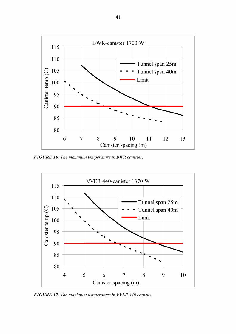
41
BWR-canister 1700 W
80
85
90
95
100
105
110
115
6 7 8 9 10 11 12 13Canister spacing (m)
Can
iste
r tem
p (C
)
Tunnel span 25mTunnel span 40mLimit
FIGURE 16. The maximum temperature in BWR canister.
VVER 440-canister 1370 W
80
85
90
95
100
105
110
115
4 5 6 7 8 9 10Canister spacing (m)
Can
iste
r tem
p (C
) Tunnel span 25mTunnel span 40mLimit
FIGURE 17. The maximum temperature in VVER 440 canister.

42
EPR-canister 1830 W
80
85
90
95
100
105
110
7 8 9 10 11 12 13Canister spacing (m)
Can
iste
r tem
p (C
)
Tunnel span 25m
Tunnel span 40m
Limit
FIGURE 18. The maximum temperature in EPR canister. 6.8 Creep strains caused by shrinking in cooling period The canisters reach their maximum temperature in the repository within 10 to 20 years af-ter the disposal. A typical maximum temperature history is shown in Figure 15. Now we presume that simultaneously when reaching the maximum temperature the canis-ter overpack is deformed due to creep or plastic deformation under the external pressure load. As a result of these deformations all the radial 1 mm gap between the cylindrical overpack and insert is closed. The copper overpack will be deformed until a full contact is reached on all surfaces between the overpack and the iron insert due to the possibly very slowly increasing external pressure load. The actual maximum local strain in the copper overpack weld will be about 3% according to (Knuutila 2001a) when the 1 mm radial gap between the overpack and the insert is forced to close due to creep (or plastic) deformation caused by external pressure load. The temperature of this bimetallic structure is then cooled within a few thousands of years from the maximum of +100 oC to about +10 oC. The temperature decrease will cause now a tensile strain into the copper overpack due to the fact that the copper is shrinking more than iron when the temperature is decreasing, which can be estimated with the formula (10)
∆ ∆ ∆ε α= − ⋅T , (10)
43
where ∆ε is the increase of the tensile strain ∆T is the temperature change of the system (10 - 100 = -90 oC), and
∆α is the difference of linear thermal expansion coefficients of the materi-als in the overpack and canister insert (17⋅10-6 -11⋅10-6 = 6⋅10-6 1/oC).
We get ∆ε = 0.00054 = 0.054%, which is of no importance when compared to the al-lowable creep strain in copper (5%). 6.9 Canister behaviour in accident conditions Canister strength and tightness in falling and dropping accidents during encapsulation or transfer to repository has been studied in (Knuutila 2001b). Canister insert is very rigid and strong. And the overpack made of hot worked copper is very tight and ductile, which ensures the gas tightness even in accident cases that cause remarkable deformations of the iron insert. The fire resistance of the canister, when transferred in a rubber wheeled transfer lorry in ramp or central tunnel of the repository, is analysed in (Lautkaski et al. 2003). Risk analy-ses of canister transport options from encapsulation plant down to repository are due to be done in near future.

44

45
7 RADIATION SHIELDING Gamma and neutron dose rates on the outer surface of the present versions of the canisters designed for the final disposal of the Finnish spent nuclear fuel have been calculated with the MCNP4C Monte Carlo code (Anttila 2005a). All three types of spent fuel disposal canisters have been analyzed. The differences be-tween the canisters result from the size and geometry of the spent fuel assemblies to be disposed of in them. In all calculations it was assumed that the bundles in the canister studied had the discharge burnup of 60 MWd/kgU and that they had been cooled for 20 years before the encapsula-tion. Radioactive properties of the spent nuclear fuel were calculated with the ORIGEN2.1 computer code. The maximum and average dose rates on the radial outer surface of three canister types were as given in Table 10. TABLE 10. The maximum and average dose rates. Gamma dose rate Neutron dose rate (mSv/h) (mSv/h) Canister type Maximum Average Maximum Average VVER 440 245 145 11 10 BWR 325 175 16 15 EPR 160 40 13 9 At the top and at the bottom of the canisters the average dose rates seem to be a little lower than on the radial outer surface. The average dose rates on the outer surface of the BWR canister are a little higher than those outside the VVER 440 canister, and the lowest dose rate is on the EPR canister due to thicker iron wall in the insert. The variation of the dose rate on the canister surface is large; the local maximum rate is typically twice the average rate, see Figure 19. Neutron dose rates are varying less, see Figure 20. The maximum radiation dose rate on the surface of the canister ends is of same order, but some lower than on the cylindrical surface. Radiation dose rates on VVER 440 and BWR canister surfaces were studied also earlier in (Anttila 1998).
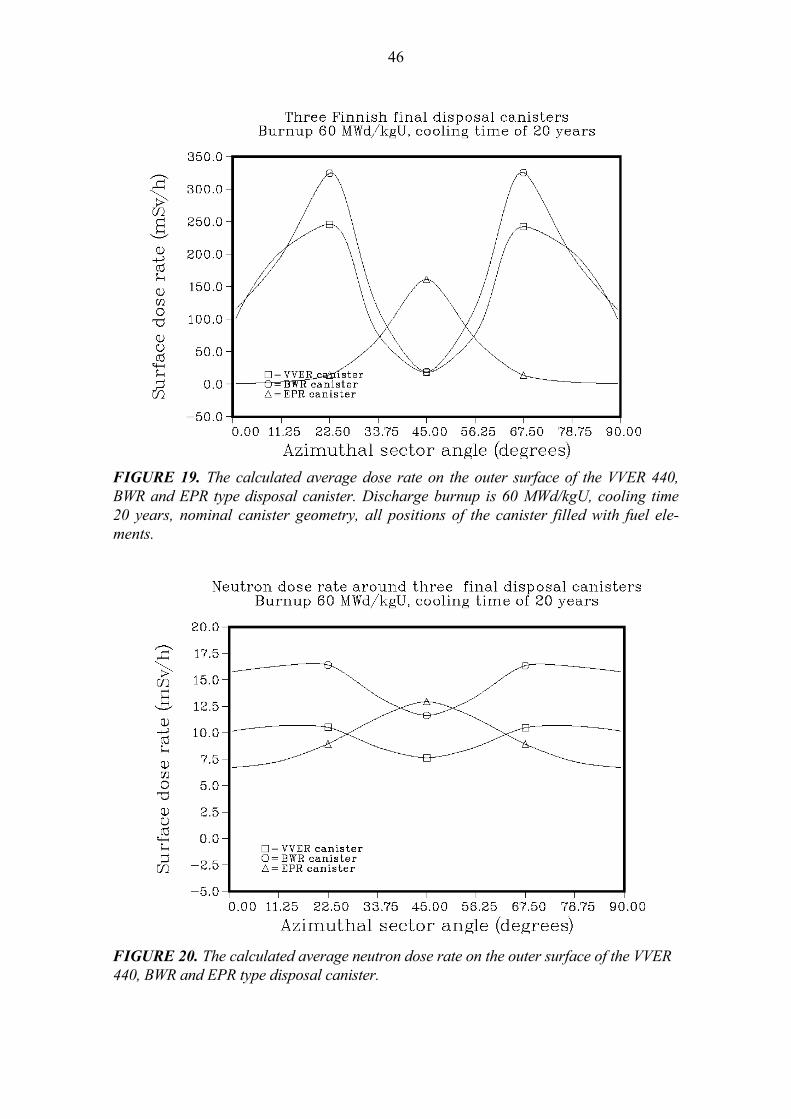
46
FIGURE 19. The calculated average dose rate on the outer surface of the VVER 440, BWR and EPR type disposal canister. Discharge burnup is 60 MWd/kgU, cooling time 20 years, nominal canister geometry, all positions of the canister filled with fuel ele-ments.
FIGURE 20. The calculated average neutron dose rate on the outer surface of the VVER 440, BWR and EPR type disposal canister.

47
8 CRITICALITY SAFETY Sub-criticality analyses are reported in (Anttila 2005b). A canister used for final disposal of nuclear fuel must be sub-critical also under very unfavourable conditions, i.e. for in-stance, when:
• the fuel in the canister is in the most reactive credible configuration, • the moderation by water is at its optimum, and • the neutron reflection on all sides is as effective as credibly possible.
The criticality safety of the copper/iron canisters developed for the final disposal of the Finnish spent nuclear fuel has been studied with the MCNP4C Monte Carlo code. All the three types of spent fuel disposal canisters have been analysed. A spent fuel disposal canister must meet the normal criticality safety criteria. The effec-tive multiplication factor must be less than 0.95 also when the canister is in the most reactive credible configuration (optimum moderation and close reflection). Uncertainties in the calculation methods may necessitate the use of an even lower reactivity limit. However, no systematic uncertainty analysis has been carried out for the Finnish dis-posal canisters. It has been proved in an earlier study (Anttila 1999) that a version of the VVER canister loaded with twelve similar fresh VVER 440 assemblies with the initial enrichment of 4.2% fulfils the criticality safety criteria. Also an earlier design of the BWR canister loaded with twelve fresh BWR assemblies of so-called ATRIUM 10x10-9Q type with the initial enrichment of 3.8% and without burnable absorbers has been proved to meet the safety criteria. Therefore, in this study (Anttila 2005b) only a few calculations have been carried out for the present versions of VVER and BWR canisters and the results are in good agreement with the previous ones. The main emphasis of this study has been on the EPR canister. This new canister type fulfils the criticality safety criteria only if the so called burnup credit principle is applied in calculations. The fuel bundles to be loaded in an EPR canister should have been irradiated at least to a burnup of 20 MWd/kgU, if the initial enrichment is about 4%.

48

49
9 MANUFACTURING PROCEDURE The canister is planned to be pre-fabricated in various workshops of subcontractors out-side the encapsulation plant. The canister components are manufactured tested and quality controlled and then assembled. The assembled canister with one end open and the lids, screws and gaskets are transported to the encapsulation site, where the loading of canister, final closing and final controls are made. 9.1 Pre-fabrication of the canister The insert is cast in a foundry, and no separate thermal treatment is needed. The openings for fuel assemblies are formed to the cast body by setting an equivalent steel structure into the mould. The prefabricated structure is welded together from steel tubes with strict di-mensional tolerances. After casting the block is cleaned up, cut into the right length and the outer surfaces are machined. Then a volumetric ND-examination is made. In addition, the dimensions and machined surfaces are examined. The lids are manufactured by ma-chining from rolled steel plate. The current versions of inserts have an integral 50 mm bot-tom, so no lid, gasket or screws are needed for the bottom. Recent insert manufacturing test in Finland has been reported in (Raiko 2003) and in Sweden in (Andersson & al. 2004). The cylinder of the overpack can be manufactured by extrusion or pierce and draw process or by pressure forging from a single cast and pre-heated billet. The cylinder is then ma-chined. The copper lids are manufactured by casting a cylindrical billet, hot pressing and machining. When using pierce and draw process, an integral bottom lid can be manufac-tured. If extrusion or pressure forging method is used, then an open cylinder can be manu-factured. In the latter case, the bottom lid is welded onto the cylinder. The pre-fabricated overpack is examined as for dimensions, surface roughness, grain size and unacceptable flaws. The pre-fabricated components are then assembled together; the insert is put inside the copper overpack. The canister with loose top lids is transported to the encapsulation plant. A special cradle is used for handling and transportation of a pre-fabricated canister. Manu-facturing processes of the canister components are described in more details in (Aalto et al. 1996), (Aalto 1998), (Koivula & Pihlainen. 2003), (Koivula & Meuronen 2004) and (Koivula et al. 2004). 9.2 Installation tolerances The nominal inside diameter of the copper overpack is 2 mm larger than the outer diame-ter of the insert. This corresponds to a radial 1 mm gap between the cylinders. This is needed due to the fact that the machining of the inside of the large soft copper cylinder cannot possibly be made with more strict tolerances. An equal nominal gap (+2 mm axial tolerance) is also designed between the lids of the insert and the overpack. The top lid is bending 1 to 2 mm inwards in the centre due to EB-welding distortion, according to prac-tical knowledge from welding tests.

50
The magnitude of the maximum strain in the copper material is evaluated in (Knuutila 2001a) to be about 3% in the lid weld in case the soft copper shell is plastically deformed the amount of the gap against the insert. 9.3 Quality controls for the pre-fabrication The quality assurance of the canister pre-fabrication is to be carried out according to the normal procedures adapted for nuclear power plant component manufacturing. The quality control plan shown on Table 11 is drafted accordingly. The workshop operations in pre-fabrication are controlled to fulfil the requirements that are set in the design report. The copper plates or tubes are examined not to include large laminar defects by means of ultrasonic test before machining. The copper welds manufactured in workshop are exam-ined additionally by radiography and the weld surface is tested with liquid penetrant after machining. The acceptance criteria in volumetric examination are drafted according to ex-isting standards, for example (SFS 2379) or equivalent. The surface shall not contain de-tectable cracks. The nodular graphite cast iron block is ND-examined before or after machining. The outer circumference is examined with ultrasonic test not to include large buried indications within the 50 to 60 mm depth measured from the outer circumference. The planar faces on the top and bottom end of the block are surface tested with liquid penetrant or magnetic particle examination for surface cracks. The planar lids are surface tested for cracks. 9.4 Sealing weld of the canister lid After loading and sealing of the insert, the canister is moved from the handling cell in ver-tical position to the electron beam welding position in a vacuum chamber. After evacuat-ing the chamber and the canister, the copper lid is installed, fixed with a tool and welded. The welding is made in at least two phases, first a tag weld all around the lid to ensure the lid positioning during the full penetration weld. The positioning of the electron beam must be targeted to the lid seam with an adequately accurate tolerance during all the welding process. The positioning and the compensation of thermal deformations during the weld-ing process can be made with a programmed steering automation or mechanical steering device, which follows the pre-fabricated trail close to the seam to be welded. This kind of a local steering device allows the possible use of a front bar on the seam to give additional material to the weld and to minimise the surface craters caused by leaking of liquid weld metal. After welding the weld surface is machined and the weld is surface tested and ND-examined by radiography or ultrasonic equipment. Figure 5 shows the details of the lid and lid weld construction. The optimal welding posi-tion of the copper lid with the procedures developed in the Finnish EB-welding develop-ment program is vertical according to the know-how and experience gained so far. The construction details may, however, change as a result of the continued procedure devel-opment. Several programs for the development of EB-welding for 50 mm thick copper

51
were carried out in Finland in 1994 - 2004. The results from welding tests are summarised in (Aalto 1998) and (Koivula & Meuronen 2004). TABLE 11. Quality control plan for canister pre-fabrication and assembly. EQUIPMENT: CANISTER FOR NUCLEAR FUEL DISPOSAL Requirements for component fabrication test reports: Name of item: copper overpack Certificate *1) Visual inspection: 3.1B Dimensional test: 3.1B Material identification: 3.1B Ultrasonic test of the cylinders or rolled plates: 3.1C Final examination: 3.1C Name of item: nodular graphite cast iron insert Certificate Visual inspection: 3.1B Dimensional test: 3.1B Material identification: 3.1B Ultrasonic test of the outer circumference: 3.1C Surface test of the machined end surfaces: 3.1C Final examination: 3.1C Name of item: steel lids Certificate Visual inspection: 3.1B Dimensional test: 3.1B Material identification: 3.1B Surface test of the machined surfaces: 3.1C Final examination: 3.1C Name of item: copper overpack, EB-welds Certificate Welding operator's performance qualification: 3.1B Weld process control: 3.1B Weld surface prefabrication: 3.1B Welding procedure qualification test: 3.1C Radiographic examination of welds *2): 3.1C Visual inspection of the welds: 3.1B Surface test for EB-weld surface: 3.1C Ultrasonic test *3): 3.1C
*1) Test reports according to requirements of DIN 50049
*2) Workshop welds only *3) Weld class WB (SFS 2379) for workshop welds
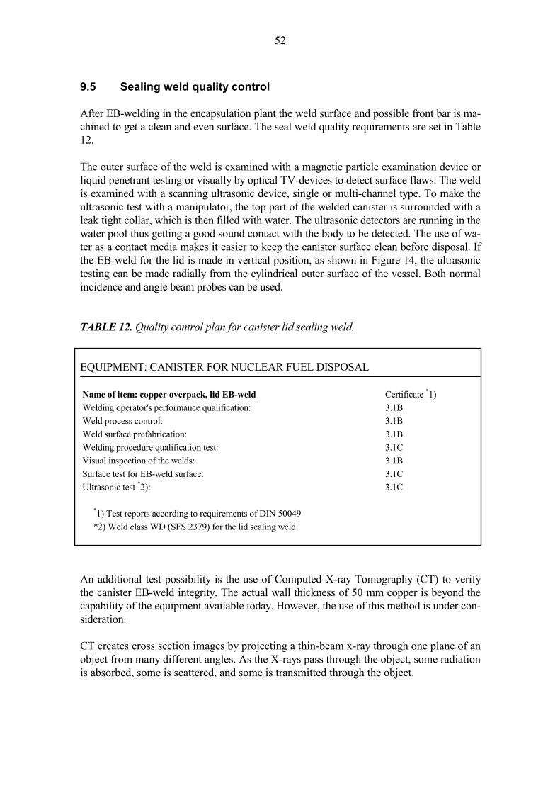
52
9.5 Sealing weld quality control After EB-welding in the encapsulation plant the weld surface and possible front bar is ma-chined to get a clean and even surface. The seal weld quality requirements are set in Table 12. The outer surface of the weld is examined with a magnetic particle examination device or liquid penetrant testing or visually by optical TV-devices to detect surface flaws. The weld is examined with a scanning ultrasonic device, single or multi-channel type. To make the ultrasonic test with a manipulator, the top part of the welded canister is surrounded with a leak tight collar, which is then filled with water. The ultrasonic detectors are running in the water pool thus getting a good sound contact with the body to be detected. The use of wa-ter as a contact media makes it easier to keep the canister surface clean before disposal. If the EB-weld for the lid is made in vertical position, as shown in Figure 14, the ultrasonic testing can be made radially from the cylindrical outer surface of the vessel. Both normal incidence and angle beam probes can be used. TABLE 12. Quality control plan for canister lid sealing weld. EQUIPMENT: CANISTER FOR NUCLEAR FUEL DISPOSAL Name of item: copper overpack, lid EB-weld Certificate *1) Welding operator's performance qualification: 3.1B Weld process control: 3.1B Weld surface prefabrication: 3.1B Welding procedure qualification test: 3.1C Visual inspection of the welds: 3.1B Surface test for EB-weld surface: 3.1C Ultrasonic test *2): 3.1C
*1) Test reports according to requirements of DIN 50049
*2) Weld class WD (SFS 2379) for the lid sealing weld An additional test possibility is the use of Computed X-ray Tomography (CT) to verify the canister EB-weld integrity. The actual wall thickness of 50 mm copper is beyond the capability of the equipment available today. However, the use of this method is under con-sideration. CT creates cross section images by projecting a thin-beam x-ray through one plane of an object from many different angles. As the X-rays pass through the object, some radiation is absorbed, some is scattered, and some is transmitted through the object.
53
The radiation transmitted through the object at each angle is measured and referred to as attenuation data. It is a measure of the reduction in X-ray intensity that results from ab-sorption and scattering by the object. In CT scanning, the attenuation data is summed over the many different angles from which it is collected using a computer in a method called, reconstruction. Reconstruc-tion essentially "builds" the CT image from the data collected and represents a cross sec-tion of the object. CT scanners typically consist of 4 hardware subsystems: a radiation source, a radiation detector system, a mechanical manipulator, and a computer with display. The radiation detector system is composed of detection elements, such as scintillating crystals and photodiodes. A data acquisition system (DAS) measures radiation data transmitted through the object and digitises it into a format that can be handled by the scanner’s computer system. A mechanical manipulator is needed to precisely move the object relative to the X-ray source and detector system. Finally, a CT system requires a computer to control the scan motion and the timing of data acquisition. The computer then also reconstructs the im-age from raw scan data. 9.6 Repair procedures If the ND-examination result of the lid weld is not acceptable, the EB-weld can be repaired by making a new weld (re-melting) in a partial or total circumference of the weld. This means that the defected area of the weld is re-melted and solidified. In case of not achieving an acceptable copper lid weld after one or more repair attempts, or for some other reason, the canister can be technically opened. Opening and unloading of the canister is described in chapter 5.3.

54
55
10 SUMMARY The new design of the canister for spent nuclear fuel disposal is presented in this report. The canister structure consists of a massive nodular graphite cast iron insert with four or twelve emplacement holes for fuel assemblies and a 50 mm thick overpack of copper. The structural details are given, the manufacturing processes are discussed and assessed, the handling, seal welding and transport to the deposition hole in the repository is described. All manufacturing and handling methods are based on technologies available today. The mechanical dimensioning calculations of the canister design with three variations (for BWR, VVER 440, and EPR fuel) are documented in this report. The mechanical strength of the design is excellent. The minimum collapse load with weakest allowable material properties and with most unfavourable manufacturing tolerances due to external pressure is 90 - 150 MPa depending on the canister insert type. The sub-criticality of the canister configuration is analysed in (Anttila 2005b). The sub-criticality analysis of the canister shows that the required safety criteria are met even in case where the fuel assemblies are fresh and the void of the canister is filled with water. A minimum burnup of 20 MWd/kgU is required for EPR canister, if the initial enrichment is about 4%, and no burnup for BWR or VVER 440 canisters is required to achieve the acceptable subcriticality. The radiation dose level on the surface of the canister is analysed in (Anttila 2005a). The results show that the design requirements are met with a good margin. The maximum of the average gamma dose rate on the canister surface is about 200 mSv/h and the local maximum is less than 350 mSv/h. Neutron dose rates outside the canisters are much lower than gamma dose rates. The maximum average value of neutron dose is 10 - 15 mSv/h. The thermal analysis of the canister and the surrounding rock in repository is presented in (Ikonen 2003a) and (Ikonen 2003b). The analysis gives the minimum grid distances of the canisters in the repository configuration. Site specific thermal properties of the rock are used in the analyses. The limiting thermal criterion is that the temperature of the canister overpack surface or bentonite buffer outside the canister shall not exceed +100 oC at any time after disposal in the repository.

56
57
REFERENCES Aalto, H. 1998. EB-welding of the copper canister for nuclear waste disposal. Final report of the development programme 1994 - 1997. Report POSIVA 98-03, Posiva Oy, Helsinki. 43 p. ISBN 951-652-041-3. Aalto, H., Rajainmäki, H. & Laakso, L. 1996. Production methods and costs of oxygen-free copper canisters for nuclear waste disposal. Report POSIVA 96-08, Posiva Oy, Hel-sinki. 30 p. ISBN 951-652-007-3. Aaltonen, P. & Varis, P. 1993. Long term corrosion tests of OFHC-coppers in simulated repository conditions - Final report. Report YJT-93-05, Nuclear Waste Commission of Finnish Power Companies, Helsinki. 32 p. Ahonen, L. 1995. Chemical stability of copper canisters in deep repository. Report YJT-95-19, Nuclear Waste Commission of Finnish Power Companies, Helsinki. 101 p. Ahonen, L. & Vieno, T. 1994. Effects of glacial meltwater on corrosion of copper canis-ters. Report YJT-94-13, Nuclear Waste Commission of Finnish Power Companies, Hel-sinki. 20 p. Andersson, C.-G., Eriksson, P., Westman, M. & Emilsson, G. 2004. Status report - Canis-ter fabrication. SKB Report R-04-23, Swedish Nuclear Fuel and Waste Management Co. (SKB), Stockholm. 67 p. + 42 p appendixes. Anttila, M. 2005a. Gamma and neutron dose rates on the outer surface of three types of final disposal canisters. Working Report 2005-14, Posiva Oy, Olkiluoto. 25 p. Anttila, M. 2005b. Criticality safety calculations for three types of final disposal canis-ters. Working Report 2005-13, Posiva Oy, Olkiluoto. 27 p. Anttila, M. 1999. Criticality safety calculations of the nuclear waste disposal canisters for twelve spent fuel assemblies. Working Report 99-03, Posiva Oy, Helsinki. 20 p. Anttila, M. 1998. Radiation protection calculations for an encapsulation plant. Working Report 98-81, Posiva Oy, Helsinki. 36 p. Arilahti, E., Bojinov, M., Mäkelä, K., Laitinen, T. & Saario, T. 2000. Stress corrosion cracking investigations of copper in groundwater with ammonium ions. Working Report 2000-46. Posiva Oy, Helsinki. 35 p. Auerkari, P. & Holmström, S. 1997. Long-term strength of EB welds of the canister for nuclear fuel disposal. Working Report 97-35e, Posiva Oy, Helsinki. 21 p. Bojinov, M. & Mäkelä, K. 2003. Corrosion of copper in anoxic 1M NaCl solution. Work-ing Report 2003-45. Posiva Oy, Helsinki. 19 p.
58
Börgesson, L., Johannesson, L.-E. & Hernelind, J. 2003. Earthquage induced rock shear through a deposition hole. Effect on the canister and buffer. Technical Report TR-04-02, Swedish Nuclear Fuel and Waste Management Co. (SKB), Stockholm. 129 p. ISSN 1404-0344. Copper and copper alloy data. 1968. Permanent file No 1 issued by CDA. Data sheet No A 4, Cu-OF. 1968 Edition. Copper Development Association. London. 10 p. Fennell, P., Graham, A., Smart, N. & Sofied, C. 2001. Grain boundary corrosion of copper canister material. Technical report TR-01-09, Swedish Nuclear Fuel and Waste Manage-ment Co. (SKB), Stockholm. 21 p. Guinan, M. W., 2001. Radiation effects in spent nuclear fuel canisters. Technical Report TR-01-32, Swedish Nuclear Fuel and Waste Management Co. (SKB), Stockholm. 26 p. Ikonen, K. 2005. Mechanical analysis of cylindrical part of canisters for spent nuclear fuel. Working report 2005-12, Posiva Oy, Olkiluoto. 43 p. Ikonen, K. 2003a. Thermal Analyses of Spent Nuclear Fuel Repository. Report POSIVA 2003-04, Posiva Oy, Olkiluoto. 61 p. ISBN 951-652-118-5. Ikonen, K. 2003b. Thermal Analyses of KBS-3H Type Repository. Report POSIVA 2003-11, Posiva Oy, Olkiluoto. 43 p. ISBN 951-652-125-8. Jeskanen, H., Kauppinen, P. & Pitkänen, J. 2001. Applicability of ultrasonic techniques to the inspection of copper canisters used for high active waste disposal. Working Report 2001-08, Posiva Oy, Helsinki. 27 p. Jeskanen, H. & Kauppinen, P. 1997. Ultrasonic inspection of electron beam welded joints in copper. Working Report 97-34e, Posiva Oy, Helsinki. 35 p. Jing, L. 2004. Numerical Modelling of Mechanical Integrity of the Copper-Cast Iron can-ister. SKI Report 2004:58, Swedish Nuclear Power Inspectorate (SKI), Stockholm. 65 p. Karnland, O. 1998. Bentonite swelling pressure in strong NaCl solutions. Report POSIVA 98-01, Posiva Oy, Helsinki. 36 p. ISBN 951-652-039-1. King, F. 2002. Corrosion of copper in alkaline chloride environments. Technical report TR-02-25, Swedish Nuclear Fuel and Waste Management Co. (SKB), Stockholm. 77 p. King, F., Ahonen, L., Taxén, C., Vuorinen, U. & Werme, L. 2002. Copper corrosion under expected conditions in a deep geologic repository. Report POSIVA 2002-01, Posiva Oy, Helsinki. 184 p. ISBN 951-652-108-8 Knuutila, A. 2001a. Long-term creep of nuclear fuel disposal canister shroud. Working Report 2001-13, Posiva Oy, Helsinki. 20 p.
59
Knuutila, A. 2001b. Canister overpack integrity assessment in handling accidents. Working Report 2001-28, Posiva Oy, Helsinki. 27 p. Koivula, J. & Pihlainen, H. 2003. Further development of the structure and fabrication of the final disposal canister. Test fabrication of a seamless overpack with an integrated bottom by pierce and draw process. Posiva Working Report 2003-49. Posiva Oy, Olkiluoto. p. 26 + 2 apps. Koivula, J. & Meuronen, I. 2004. Further development of the structure and fabrication of the final disposal cylinder. Closing the lid with high voltage EBW. Posiva Working Report 2003-78. Posiva Oy, Olkiluoto. 36 p. + 166 apps. Koivula, J., Mäkinen, P. & Raiko, H. 2004. Further development of the structure and fabrication of the final disposal canister – Fabrication and costs of the canister. Working Report 2004-49, Posiva Oy, Olkiluoto. 37 p. Kukkola, T. 2002. Encapsulation plant description, Independent facility. Working Report 2002-03, Posiva Oy, Olkiluoto. 57 p. La Pointe, P. & Hermanson, J. 2002. Estimation of rock movements due to future earth-quakes at four candidate sites for a spent fuel repository in Finland. Report POSIVA 2002-02, Posiva Oy, Helsinki. 89 p. Lautkaski, R., Ikonen, K. & Hostikka S. 2003. Consequences of fire of the canister trans-fer vehicle in repository and access tunnel. Working Report 2003-35, Posiva Oy, Olkilu-oto. 59 p. (In Finnish). Milodowski, A., Styles, M. & Hards, V. 2000. A natural analogue for copper waste can-isters: The copper-uranium mineralised concretions in the Permian mudrocks of south Devon, United Kingdom. Technical Report TR-00-11, Swedish Nuclear Fuel and Waste Management Co. (SKB), Stockholm. 121 p. Pietikäinen, L. 2003. Design of encapsulation plant´s canister transfer machine. Working Report 2003-08, Posiva Oy, Olkiluoto. 34 p. (In Finnish). Raiko, H. & Salo, J.-P. 1992. The design analysis of ACP-canister for nuclear waste dis-posal. Report YJT-92-05, Nuclear Waste Commission of Finnish Power Companies, Hel-sinki. 39 p. ISSN-0359-548X. Raiko, H. & Salo, J.-P. 1996. Design report of the canister for nuclear fuel disposal. Re-port POSIVA 96-13, Posiva Oy, Helsinki. 51 p. ISBN 951-652-012-X. Raiko, H. & Salo, J.-P. 1999. Design report of the disposal canister for twelve fuel as-semblies. Report POSIVA 99-18, Posiva Oy, Helsinki. 64 p. ISBN 951-652-073-1. Raiko, H. 2003. Test Manufacture of a Canister Insert. Working Report 2003-59. Posiva Oy, Olkiluoto. 21 p.
60
Rajainmäki, H., Aalto, H., Raiskio, J., Pohjavirta, J., Laakso, L. & Raiko, H. 1995. EB-welding procedure development for the manufacture of a massive copper canister. Optimi-sation of the parameters for basic welding. Working Report TEKA-95-08, Teollisuuden Voima Oy, Helsinki. 67 p. (In Finnish). Rasilainen, K (Ed.). 2004. Localisation of the SR97 Process Report for Posiva´s Spent Fuel Repository at Olkiluoto. Report POSIVA 2004-05. Posiva Oy, Olkiluoto167 p. ISBN 951-652-131-2. Rossi, J., Raiko, H., Suolanen, V. & Ilvonen, M. 1999. Assessment of radiation doses due to normal operation, incidents and accidents of the final disposal facility. Report POSIVA 99-16. Posiva Oy, Helsinki. 85 p. ISBN 951-652-071-5. (In Finnish). Saario, T., Laitinen, T., Mäkelä, K. & Bojinov, M. 1999. Literature survey on stress cor-rosion cracking of Cu in presence of nitrites, ammonia, carbonates and acetates. Work-ing Report 99-57, Posiva Oy, Helsinki. 20 p. Salo, J.-P. & Raiko, H. 1990. The copper/steel canister design for nuclear waste disposal. TVO/KPA Turvallisuus ja tekniikka, Work Report 90-10, Rev. 1., Teollisuuden Voima Oy, Helsinki. 26 p. SFS-EN 10025 standard, Hot rolled products of non-alloy structural steels. 1994. Finnish Standards Association SFS. Helsinki. 44 p. SFS-EN 1563 standard, Founding. Spheroidal graphite cast irons. 1998. Finnish Standards Association SFS. Helsinki. 35 p. SFS 2379 standard, Welding. Fusion welded joints in steel. Classification. 1983. Finnish Standards Association SFS. Helsinki. 13 p. SFS 2610 standard, Design of pressure vessels, Basic requirements. 1990. Finnish Stan-dards Association SFS. Helsinki. 8 p. SFS 2611 standard, Design of pressure vessels, Cylindrical and spherical shell subject to internal pressure. 1981. Finnish Standards Association SFS. Helsinki. 4 p. SFS 2615 standard, Design of pressure vessels, Flat end and flat cover. 1985. Finnish Standards Association SFS. Helsinki. 14 p. SFS 2862 standard, Design of pressure vessels, Shell subject to external pressure. 1987. Finnish Standards Association SFS. Helsinki. 8 p. SFS 2905 standard, Oxygen free copper for electrical purposes. 1975. Finnish Standards Association SFS. Helsinki. 6 p. SFS 3292 standard, Design of pressure vessels. Stress analysis. 1979. Finnish Standards Association SFS. Helsinki. 10 p.

61
SFS 3345 standard , Materials for pressure vessels. Grey iron and nodular iron. 1987. Fin-nish Standards Association SFS. Helsinki. 6 p. Taxén, C. 2002a. Pitting corrosion of copper. An equilibrium-mass transport study. Technical report TR-02-22. Swedish Nuclear Fuel and Waste Management Co. (SKB), Stockholm. 123 p. Taxén, C. 2002b. Pitting corrosion of copper. Further model studies. Technical report TR-02-23. Swedish Nuclear Fuel and Waste Management Co. (SKB), Stockholm. 69 p. Vieno, T. & Nordman, H. 1999. Safety assessment of spent fuel disposal in Hästhol-men, Kivetty, Olkiluoto and Romuvaara TILA-99. Report POSIVA 99-07, Posiva Oy, Helsinki. 253 p. ISBN 951-652-062-6. Werme, L. 1998. Design premises for canister for spent nuclear fuel. Technical Report TR-98-08, Swedish Nuclear Fuel and Waste Management Co. (SKB), Stockholm. 46 p. ISSN 0284-3757. Werme, L. & Eriksson, J. 1995. Copper canister with cast inner component. Technical Report TR-95-02, Swedish Nuclear Fuel and Waste Management Co. (SKB), Stock-holm. 14 p. ISSN 0284-3757. YVL-guide 2.1, Nuclear power plant systems, structures and components and their safety classification. 2000. Radiation and Nuclear Safety Authority (STUK), Helsinki. 10 p. YVL-guide 8.5, Operational safety of a disposal facility for spent nuclear fuel. 2002. Ra-diation and Nuclear Safety Authority (STUK), Helsinki. 9 p.


1 (1) LIST OF REPORTS POSIVA-REPORTS 2005 POSIVA 2005-01 Plan for Safety Case of Spent Fuel Repository at Olkiluoto Timo Vieno, VTT Processes Ari T. K. Ikonen, Posiva Oy February 2005 ISBN 951-652-133-9 POSIVA 2005-02 Disposal Canister for Spent Nuclear Fuel Design Report Heikki Raiko, VTT Processes July 2005 ISBN 951-652-134-7