Displacement-Based Seismic Design -...
27
NATIONAL TECHNICAL UNIVERSITY OF ATHENS LABORATORY FOR EARTHQUAKE ENGINEERING Displacement-Based Seismic Design Ioannis N. Psycharis I. N. Psycharis “Displacement-Based Seismic Design” 2 Force-Based Seismic Design (codes) ● Although the structure is designed to yield during the design earthquake, only the elastic part of the response, up to yield, is examined. The analysis is based on the corresponding secant stiffness. ● The design loads are determined by dividing the seismic loads that would have been developed to the equivalent linear system by the behaviour factor, q. ● A unique value of q is considered for the whole structure, which does not reflect the real response. ● In order to satisfy the non-collapse criterion, capacity design rules and proper detailing are applied, which lead to safe and rather conservative design. However, the real deformation of the structure (displacements) is usually underestimated.
Transcript of Displacement-Based Seismic Design -...

NATIONAL TECHNICAL UNIVERSITY OF ATHENSLABORATORY FOR EARTHQUAKE ENGINEERING
Displacement-Based Seismic Design
Ioannis N. Psycharis
I. N. Psycharis “Displacement-Based Seismic Design” 2
Force-Based Seismic Design (codes)
● Although the structure is designed to yield during the design earthquake, only the elastic part of the response, up to yield, is examined. The analysis is based on the corresponding secant stiffness.
● The design loads are determined by dividing the seismic loads that would have been developed to the equivalent linear system by the behaviour factor, q.
● A unique value of q is considered for the whole structure, which does not reflect the real response.
● In order to satisfy the non-collapse criterion, capacity design rules and proper detailing are applied, which lead to safe and rather conservative design. However, the real deformation of the structure (displacements) is usually underestimated.

I. N. Psycharis “Displacement-Based Seismic Design” 3
Displacement-Based Design (DBD)
● The real deformation of each member of the structure is examined.
● Two approaches:
♦ Method A
Check of an already pre-designed structure and make improvements (increase dimensions of cross section) only to members that have problems.
♦ Method B
Design from the beginning the structure for a certain displacement (Direct Displacement-Based Design - DDBD). The design displacement is usually determined by serviceability or ultimate capacity considerations.
I. N. Psycharis “Displacement-Based Seismic Design” 4
Cu
A1. SDOF Structures
Developed for bridge piers (Moehle 1992):
Moments Curvatures Displacements
δy δp
δu

I. N. Psycharis “Displacement-Based Seismic Design” 5
A1. SDOF Structures
2L
LL)cc(δδ hhyuyu
where: = yield displacement
cy = yield curvature
Lh = length of plastic hinge
This relation yields to:
which relates the ultimate curvature cu with the ultimate displacement δu.
3Lc
δ2
yy
2L
LL
δδcc
hh
yuyu
I. N. Psycharis “Displacement-Based Seismic Design” 6
A1. SDOF Structures
But cu is directly related to critical strains of the cross section.
For example, the strain εu of the edge fiber can be written as:
hβε
c uu
Neutral axis
Thus, the ultimate displacement, δu, can be associated with the critical strains of the cross section of the plastic hinge.

I. N. Psycharis “Displacement-Based Seismic Design” 7
A1. SDOF Structures
Simplification for:
● Cy small compared to Cu Cy 0
● L–Lh/2 L
● Lh h/2
L
L
C C
Ιδεατό διάγραμμα καμπυλοτήτων
h
p y
u C
Προσεγγιστικό διάγραμμα καμπυλοτήτων
u C
L h
Real diagram of curvatures
Simplified diagram of curvatures
β2ε
Lδ uu
I. N. Psycharis “Displacement-Based Seismic Design” 8
A1. SDOF Structures
Step 1
Calculate the effective period, Teff, using the secant stiffness at the theoretical yield point.
Step 2
Calculate the ultimate displacement, δu, assuming that the equal displacement rule holds, i.e. from the elastic response spectrum for T=Teff and ζ=5%.
Step 3
Calculate the corresponding ultimate curvature, cu.
Step 4
Calculate the corresponding critical strains, εu, and check if they are acceptable.

I. N. Psycharis “Displacement-Based Seismic Design” 9
A1. SDOF Structures
a) If the critical check concerns the compression of the concrete:
Let maxεu = 4‰. Also, βh = 0.36 m, β = 0.36/1.80 = 0.2.
b) If the critical check concerns the tension of the steel:
Let maxεu = 6%. Also, βh = 1.35 m, β = 1.35/1.8 = 0.75.
(a) (b)
01.022.0
004.0Lδu
04.0275.0
06.0Lδu
I. N. Psycharis “Displacement-Based Seismic Design” 10
A2. Multi-storey Buildings
Panagiotakos & Fardis (1996)
● Pre-dimensioning
♦ Suggested to be based on the serviceability earthquake (can be taken equal to 40-50% of the design earthquake, depending on the importance) using the Force-Based design.
♦ Elastic analysis (q=1) with simplified methods (e.g. lateral force method of EC8). However, the stiffness corresponding to the cracked sections must be used (can be taken equal to 25% of the uncracked).
♦ The period can be determined from the Rayleigh quotient:
where and δi = static displacement of the ith floor due to loads Pi.
n
1iii
n
1i
2ii
δP
δmπ2T
n
1jjj
iioi
zm
zmVP

I. N. Psycharis “Displacement-Based Seismic Design” 11
A2. Multi-storey Buildings
Step 1
Calculate the required reinforcement of the beams (spans and supports) and of the columns and walls at their base (foundation level) for the most adverse combination:
● 1.35 G + 1.5 Q (non-seismic combination); or
● G + ψ2 Q + Es (seismic combination, Εs = serviceability earthquake).
Step 2
Calculate the required reinforcement of the columns and the walls at the rest of their height using the capacity design procedure.
Step 3
Calculate the required shear reinforcement using capacity design.
I. N. Psycharis “Displacement-Based Seismic Design” 12
A2. Multi-storey Buildings
Step 4
Calculate more accurately the effective period, Teff, using the secant stiffness at the yield point of each section, taking under consideration the actual reinforcement. Approximate formulas from the literature can be employed.
Step 5
Calculate the displacement δe of the equivalent SDOF system:
δe = Sde(Teff, ζ=5%).
In the following, the subscript “e” denotes the equivalent SDOF system.

I. N. Psycharis “Displacement-Based Seismic Design” 13
A2. Multi-storey Buildings
Step 6
Calculate the rotations at the end sections of the structural members (beams, columns):
● The displacement at the ith storey can be written in terms of the displacement of the equivalent linear system as:
δi = λi δe
where λi is an unknown coefficient. Similarly,
ai = λi ae
I. N. Psycharis “Displacement-Based Seismic Design” 14
A2. Multi-storey Buildings
● Basic assumptions
1. The total seismic load of the multi-storey structure is equal to the one of the equivalent SDOF structure (i.e. the base shear V0 is the same):
Also,
eee amP
n
1iiie
n
1ieii
n
1iii
n
1iie λmaaλmamPP
n
1iiie λmm
n
1jjj
iie
e
eiieiiiii
λm
λmP
mP
λmaλmamP
e
ii δ
δλ
n
1jjj
iiei
δm
δmPP

I. N. Psycharis “Displacement-Based Seismic Design” 15
A2. Multi-storey Buildings
2. The total work of the seismic loads is the same in the multi-storey and the equivalent SDOF structure:
or
(from the previous relation between Pi and Pe)
n
1iiiee δPδP
e
n
1iii
e P
δPδ
n
1iii
n
1i
2ii
e
δm
δmδ
I. N. Psycharis “Displacement-Based Seismic Design” 16
A2. Multi-storey Buildings
Let us define φi as the ratio of the displacement at the ith storeyover the top displacement:
Then,
♦ The coefficients φi denote the deformation of the structure at the maximum displacement and are not known a priori.
♦ If the expected plastic deformations are significant, the analysis can be performed considering the following two “extreme” cases:
en
1i
2ii
n
1iii
top δφm
φmδ
top
ii δ
δφ

I. N. Psycharis “Displacement-Based Seismic Design” 17
A2. Multi-storey Buildings
Case 1
In typical building, and due to the capacity design that has been performed, plastic hinges are expected to form at the base of the columns and the walls and at the ends of the beams.
Then, assuming that the plastic deformation is significantly larger than the elastic one:
and
δ top
θ
i
z i
H tot θ
tot
ii H
zφ en
1i
2ii
n
1iii
tot
top δzm
zm
Hδ
tot
top
Hδ
θ
I. N. Psycharis “Displacement-Based Seismic Design” 18
A2. Multi-storey Buildings
Case 2
In case that it is expected that a “soft storey” mechanism will be developed at the jth floor in the ultimate deformation, it can be set:
In that case:
δtop = δe and
δ top
z j z j-1
j
j-1
θ
n...jifor1
)1j(...1ifor0φi
1jj
top
zzδ
θ

I. N. Psycharis “Displacement-Based Seismic Design” 19
A2. Multi-storey Buildings
Intermediate case
For less extreme cases, it can be assumed that the relation of the storey displacements for inelastic response is similar to the one for elastic response. Then the coefficients φi can be assumed equal to the ones that correspond to the elastic displacements up to yield:
The values of the 1st eigenmode can be used in that case as an approximation.
eltop
eli
i δδ
φ
I. N. Psycharis “Displacement-Based Seismic Design” 20
A2. Multi-storey Buildings
Inelastic storey displacements
After the values of φi have been determined with one of the above-mentioned methods, the inelastic storey displacements can be determined from the top displacement:
and the storey drifts are:
Step 6
Check that the above required rotations θi at the ends of the structural elements are within the allowable limits.
n
1j
2jj
n
1jjj
iei
φm
φmφδδ
i1i
i1ii zz
δδθ
I. N. Psycharis “Displacement-Based Seismic Design” 21
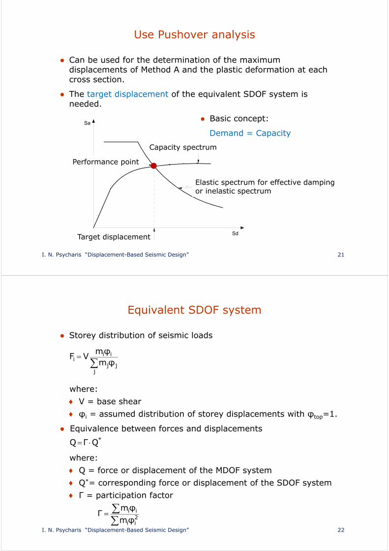
Use Pushover analysis
● Can be used for the determination of the maximum displacements of Method A and the plastic deformation at each cross section.
● The target displacement of the equivalent SDOF system is needed.
● Basic concept:
Demand = Capacity
SdΣτοχευόμενη μετακίνηση
Sa
Καμπύλη ικανότητας
Ελαστικό φάσμα σχεδιασμού για ενεργό απόσβεσηή ανελαστικό φάσμα σχεδιασμού
Σημείοεπιτελεστικότητας
Capacity spectrum
Elastic spectrum for effective damping or inelastic spectrum
Performance point
Target displacement
I. N. Psycharis “Displacement-Based Seismic Design” 22
Equivalent SDOF system
● Storey distribution of seismic loads
where:
♦ V = base shear
♦ φi = assumed distribution of storey displacements with φtop=1.
● Equivalence between forces and displacements
where:
♦ Q = force or displacement of the MDOF system
♦ Q*= corresponding force or displacement of the SDOF system
♦ Γ = participation factor
jjj
iii φm
φmVF
*QΓQ
2
ii
ii
φmφm
Γ

I. N. Psycharis “Displacement-Based Seismic Design” 23
Calculation of max displacements (ATC-40)
Step 1
Change elastic design spectrum to ADRS format
T Sd
Sa
0 0 T1
T1
T2
T2
T3
T3
T4
T4
Sa
d2
2
a STπ4
S
a2
2
d Sπ4T
S
a
d
SS
π2T
I. N. Psycharis “Displacement-Based Seismic Design” 24
Calculation of max displacements (ATC-40)
Step 2
Calculate the capacity curve and change it to capacity spectrum
● V = base shear
● ∆ = top displacement
● mtot = total mass of MDOF
●
●
∆
VΚαμπύλη ικανότηταςκατασκευής
F3
0 Sd
SaΦάσμα ικανότηταςισοδύναμου μονοβαθμίου
0
∆
V=ΣFi
F4
F2
F1
tota mα
VS
Γ∆
Sd
tot
*
tot
ii2iitot
2ii
mm
Γm
φmΓφmm
φmα
ii* φmm
Base shear
Top displacement
Capacity curve Capacity spectrumSa
Sd

I. N. Psycharis “Displacement-Based Seismic Design” 25
Calculation of max displacements (ATC-40)
Step 3
First estimation of the performance point
Sa
Sd 0
Ko=Kcr
a 1
δ 1
1η δοκιμή σημείου επιτελεστικότητας
Ελαστικό φάσμα για ζ=5%
Φάσμα αντίστασης Capacity spectrum
First estimation of the performance point
Elastic spectrum for 5% damping
I. N. Psycharis “Displacement-Based Seismic Design” 26
Sa
Sd 0
Ko
a 1
δ 1
Ελαστικό φάσμαγια ζ=5%
Φάσμα αντίστασης
A2 A1
δ y
a y
Calculation of max displacements (ATC-40)
Step 4
Bilinear representation of capacity spectrum
Capacity spectrum
Elastic spectrum for 5% damping

I. N. Psycharis “Displacement-Based Seismic Design” 27
Calculation of max displacements (ATC-40)
Step 5
Calculation of effective damping
0S
Dhyst E
Eπ41
ζ
11
1y1yeff δa
)aδδa(κ7.635)%(ζ
Earthquake durationNew structures of
good seismic performance
Structures of medium seismic
performance
Structures of poor seismic
performanceShort
(close to the epicenter) A B C
Long(away from the epicenter) Β C C
Type of structure ζhyst (%) κ
A
16.25 1.00
> 16.25
B
< 25 0.67
> 25
C All values 0.33
uu
uyuy
δa)aδδa(51.0
13.1
uu
uyuy
δa)aδδa(446.0
845.0
Sa
Sd δu
au
δy
ay
Ko Keff
ES0
ED
I. N. Psycharis “Displacement-Based Seismic Design” 28
Sa
Sd 0
Ko
a 1
δ 1
Ελαστικό φάσμα για ζ=5%
Φάσμα αντίστασης
δ y
ay Ελαστικό φάσμα για ζ=ζeff
Νέο σημείο επιτελεστικότητας a 2
δ 2
1:BS
1:BL
σταθ. Τ
σταθ. Τ
Calculation of max displacements (ATC-40)
Step 5 (cont.)
Design spectrum for ζ = ζeff
Capacity spectrum
Elastic spectrum for 5% damping
Elastic spectrum for ζ=ζeff
New performance point
min,Aeff
SA SR
12.2ζln68.021.3
B1
SR
min,Veff
LV SR
65.1ζln41.031.2
B1
SR

I. N. Psycharis “Displacement-Based Seismic Design” 29
Calculation of max displacements (ATC-40)
Step 5 (cont.)
Minimum values of SRA,min, SRV,min
Step 6
Check convergence
● If 0.95δ1 < δ2 < 1.05δ1 O.K.
● If not, repeat from step 5
Type of structure SRA,min SRV,min
A 0.33 0.50
B 0.44 0.56
C 0.56 0.67
I. N. Psycharis “Displacement-Based Seismic Design” 30
Calculation of max displacements (ATC-40)
Step 7
Deformation of MDOF system and checks
● Calculate top displacement: ∆ = ΓSd
● Perform pushover analysis up to top displacement equal to ∆and calculate the ultimate rotations at the joints.
● Check rotations of sections according to DBD.

I. N. Psycharis “Displacement-Based Seismic Design” 31
Method B: DDB design
● The design is based on the target displacement, δu.
● The target displacement is defined by
♦ Serviceability criteria; or
♦ Ultimate capacity criteria.
● The “substitute structure” is used:
♦ Effective stiffness at the maximum displacement
♦ Effective damping considering the hysteretic energy dissipation.
● The design is not based on the displacement ductility.
I. N. Psycharis “Displacement-Based Seismic Design” 32
B1. SDOF Structures
Developed for bridge piers (Kowalsky, Priestley & Macrae, 1995)
The method is based on the “substitute structure”
♦ Effective stiffness, Keff
♦ Effective damping, ζeff
♦ Effective period, Teff
P
δ
P
P
u
y
y u δ δ
Κ
eff
eo
cr
Κ
Κ

I. N. Psycharis “Displacement-Based Seismic Design” 33
B1. SDOF Structures
Step 1
Definition of the design parameters:
● m = mass
● L = height of pier
● fc = concrete grade
● fy = yield stress of reinforcement
● Ε = Young’s modulus of elasticity
● δu = target displacement.
● An elastic displacement response spectrum must be available for various values of damping
I. N. Psycharis “Displacement-Based Seismic Design” 34
B1. SDOF Structures
Step 2
Determination of the substitute structure:
● Guess an initial value for the yield displacement, δy.
This value is arbitrary and will be used as the first approximation. Suggestion: δy = 0.005L.
● Calculate the corresponding ductility μ = δu / δy.
● Calculate the corresponding effective damping, ζeff.
● Effective damping consists of two terms:
♦ the viscous damping, which is assumed equal to the one for elastic behaviour (5% for RC structures); and
♦ the hysteretic damping, which can be estimated from the ductility using relations from the literature. Such a relation, based on the Takeda model, is suggested by the authors:
π
μ05.0μ95.0
105.0ζeff

I. N. Psycharis “Displacement-Based Seismic Design” 35
B1. SDOF Structures
Step 2 (cont’d)
● Calculate the effective period of the substitute structure from the value of displacement spectrum that corresponds to Sd=δuand ζ=ζeff.
● Calculate the effective stiffness of the substitute structure:
T
S
ζ=0%
2% 5%
10%
20%
50%
d
eff ζ
u δ
eff T
2eff
2
eff Τmπ4
K
I. N. Psycharis “Displacement-Based Seismic Design” 36
B1. SDOF Structures
Step 3
Calculate the design actions for the dimensioning of the pier.
● Seismic force at maximum displacement: Pu = Keff δu.
● Seismic force to be used for the design of the pier: Pd=Py:
Pu = Pd + rKcr(δu – δy)
where r=Keo/Kcr
Pu = Pd + rPd(μ – 1)
● Design moment at the base of the column: Md = Pd L
1rμrP
P ud
P
δ
P
P
u
y
y u δ δ
Κ
eff
eo
cr
Κ
Κ

I. N. Psycharis “Displacement-Based Seismic Design” 37
B1. SDOF Structures
Step 4
● Choose the necessary cross section and calculate the required reinforcement at the base of the pier for the moment Md and the axial load N.
● Calculate the elastic stiffness Kcr from the estimated moment of inertia of the cracked section, Icr, using the actual reinforcement. Relations from the literature can be used
For circular cross section:
ρ = percentage of reinforcement
Ig = geometric moment of inertia
Ag = geometric area of section
N = axial force.
Then:
gc
2
g
cr
AfΝ
)ρ05.0(2051.0ρ1221.0II
3cr
cr LEI3
K
I. N. Psycharis “Displacement-Based Seismic Design” 38
B1. SDOF Structures
Step 5 (optional)
Check whether the selected section leads to reasonable results.
● “Elastic” period:
● “Plastic” period: where Keo = rKcr
In general: Τcr < Τeff < Τeo
● If Teff is not close to the limits, the design is correct and we proceed to the following step.
● If Τeff is close to Τcr, the response is close to the elastic. In this case, the design will lead to large amount of reinforcement and small required ductility.
● If Τeff is close to Τeo, the design will lead to small amount of reinforcement and large required ductility.
crcr K
mπ2T
eoeo K
mπ2T

I. N. Psycharis “Displacement-Based Seismic Design” 39
B1. SDOF Structures
Step 5 (cont’d)
P
δ
P P
u y
y uδ δ
Κ
eff
eo
cr Κ
Κ
P
δ
P
P
u
y
y u δ δ
Κ
eff
eo
cr
Κ
Κ
Teff close to Tcr
Suggested action: Increase dimensions of cross section (decrease δy)
Teff close to Teo
Suggested action: Decrease dimensions of cross section (increase δy)
I. N. Psycharis “Displacement-Based Seismic Design” 40
B1. SDOF Structures
Step 6
Check convergence.
● Calculate new yield displacement:
● If , where ε = required accuracy (e.g. ε=5%), stop iterations. Otherwise, repeat procedure from step 2 using δy’ as the yield displacement.
Step 7After convergence is achieved, calculate the horizontal reinforcement (stirrups) to guarantee capacity of the section to develop the required curvature ductility:
where Lh = length of plastic hinge.
cr
dy K
Pδ
yyy δεδδ
)L/L5.01()L/L(31μ
1μhh
∆C

I. N. Psycharis “Displacement-Based Seismic Design” 41
B1. SDOF Structures
Example
Step 1
● m = 500 Mgr
● L = 5.0 m
● fc = 40 MPa
● fy = 400 MPa
● E = 31.62 GPa
● δu/L = 3% δu = 0.03 5.0 = 0.15 m.
I. N. Psycharis “Displacement-Based Seismic Design” 42
B1. SDOF Structures
Step 2
● δy = 0.005 L = 0.025 m
● μ = δu / δy = 0.150 / 0.025 = 6.0
●
● Let Teff = 1.627 sec, as derived from response spectrum for:
Se = δu = 0.15 m and ζ = ζeff = 0.206
●
206.0π
0.605.00.6
95.01
05.0ζeff
m/ΚΝ7457627.1
500π4Τ
mπ4K 2
2
2eff
2
eff
I. N. Psycharis “Displacement-Based Seismic Design” 43
B1. SDOF Structures
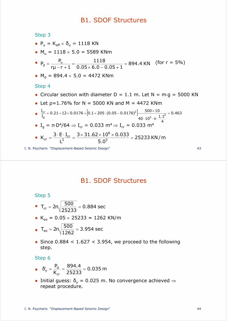
Step 3
● Pu = Keff δu = 1118 KN
● Mu = 1118 5.0 = 5589 KNm
● (for r = 5%)
● Md = 894.4 5.0 = 4472 KNm
Step 4
● Circular section with diameter D = 1.1 m. Let N = mg = 5000 KN
● Let ρ=1.76% for N = 5000 KN and M = 4472 KNm
●
● Ιg = πD4/64 Icr = 0.033 m4 Icr = 0.033 m4
●
KN4.894105.00.605.0
11181rμr
PP u
d
463.0
41.1
π1040
10500)0176.005.0(2051.00176.01221.0
II
23
2
g
cr
m/KN252330.5
033.01062.313L
IE3K 3
6
3cr
cr
I. N. Psycharis “Displacement-Based Seismic Design” 44
B1. SDOF Structures
Step 5
●
● Κeo = 0.05 25233 = 1262 KN/m
●
● Since 0.884 < 1.627 < 3.954, we proceed to the following step.
Step 6
●
● Initial guess: δy = 0.025 m. No convergence achieved repeat procedure.
sec884.025233500
π2Tcr
sec954.31262500
π2Teo
m035.025233
4.894KP
δcr
dy

I. N. Psycharis “Displacement-Based Seismic Design” 45
B2. MDOF structures
Kalvi & Kingsley (1995) for bridges with many piers
The method starts with an initial guess for the displacements, which is improved through iterations.
P i
m i
δ i
I. N. Psycharis “Displacement-Based Seismic Design” 46
B2. MDOF Structures
Equivalent DSOF system
● Ke = stiffness of equivalent SDOF
● ζe = damping of equivalent SDOF
● δe = displacement of equivalent SDOF
● Ρe = seismic force of equivalent SDOF
Assume that the displacements, δi, of the MDOF system can be determined from the displacement of the equivalent SDOF, δe, through appropriate coefficients φi:
δi = φi δe
Assume that the accelerations follow the same distribution:
ai = φi ae

I. N. Psycharis “Displacement-Based Seismic Design” 47
B2. MDOF Structures
Equivalent DSOF system (cont’d)
● Equal seismic force in the two systems:
But, Pe = meae , thus
Also,
and
therefore
n
1iiie
n
1ieii
n
1iii
n
1iie φmaaφmamPP
n
1iiie φmm
n
1jjj
iie
e
eiieiiiii
φm
φmP
mP
φmaφmamP
e
ii δ
δφ
n
1jjj
iiei
δm
δmPP
I. N. Psycharis “Displacement-Based Seismic Design” 48
B2. MDOF Structures
Equivalent DSOF system (cont’d)
● Equal work of the seismic forces in the two systems:
Properties of equivalent SDOF system
● Stiffness of equivalent SDOF system:
● The damping of the equivalent SDOF system, ζe, is calculated from the damping of each pier, ζi, which depends on the ductility μi that is developed at the pier and can be derived using relations from the literature.
n
1iiiee δPδP
n
1iiie
n
1i
2iie
e
n
1iii
e
δmP
δmP
P
δPδ
n
1iii
n
1i
2ii
e
δm
δmδ
e
ee δ
PK
I. N. Psycharis “Displacement-Based Seismic Design” 49
B2. MDOF Structures
Step 1
● Define the target displacement δi,u of each pier.
● In order to have similar damage in all piers, we can assume same drifts: δi/Ηi. Thus:
δi,u = drift Ηi
● Make an initial estimation of the yield displacements of the piers, δi,y and calculate the ductility for each pier:
● Calculate the equivalent damping, ζe, for each pier from the corresponding ductility (similarly to the SDOF systems).
y,i
u,ii δδ
μ
I. N. Psycharis “Displacement-Based Seismic Design” 50
B2. MDOF Structures
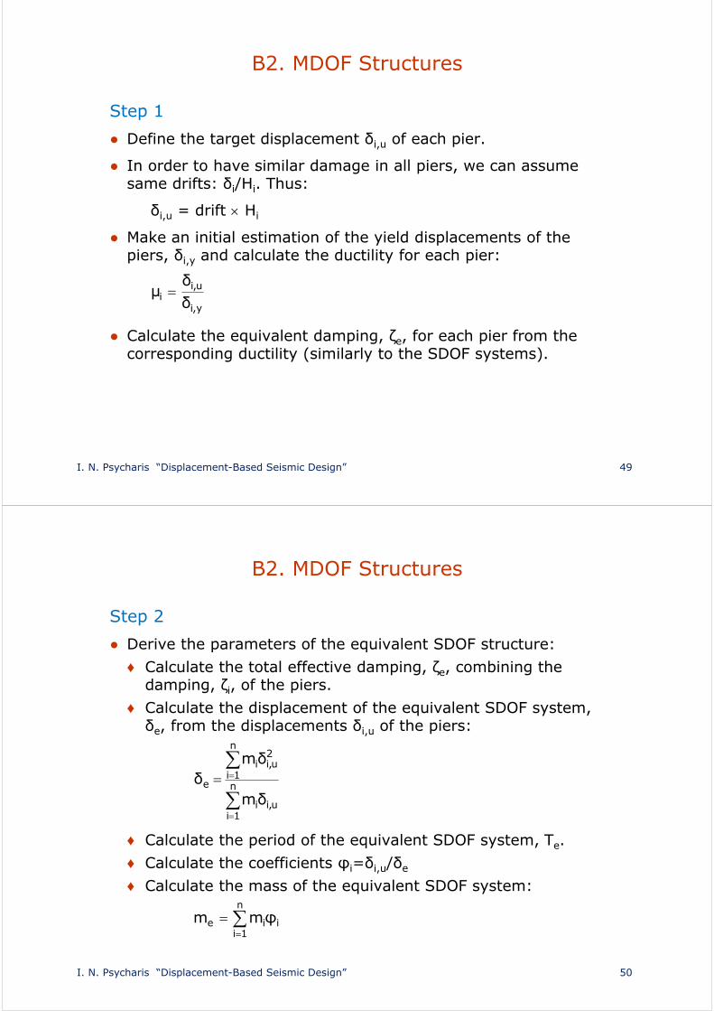
Step 2
● Derive the parameters of the equivalent SDOF structure:
♦ Calculate the total effective damping, ζe, combining the damping, ζi, of the piers.
♦ Calculate the displacement of the equivalent SDOF system, δe, from the displacements δi,u of the piers:
♦ Calculate the period of the equivalent SDOF system, Τe.
♦ Calculate the coefficients φi=δi,u/δe
♦ Calculate the mass of the equivalent SDOF system:
n
1iu,ii
n
1i
2u,ii
e
δm
δmδ
n
1iiie φmm

I. N. Psycharis “Displacement-Based Seismic Design” 51
B2. MDOF Structures
Step 2
● Then:
Pe = Keδe
and the forces Pi at the top of each pier can be derived:
2e
e2
e Tmπ4
K
n
1jjj
iiei
δm
δmPP
I. N. Psycharis “Displacement-Based Seismic Design” 52
B2. MDOF Structures
Step 3
● Static analysis of the system for the forces Pi and calculation of the displacements and the forces that are developed. The inelastic response must be considered, e.g. nonlinear static (pushover) analysis or elastic analysis with reduced stiffness for the piers.
● Calculate the accuracy εi of the obtained displacements δi of the piers, similarly to the SDOF systems.
Step 4: checks
● If satisfactory accuracy is not achieved, change dimensions of cross sections or reinforcement of piers and repeat procedure.
● If satisfactory accuracy is achieved, verify that the piers can bear the loads.

I. N. Psycharis “Displacement-Based Seismic Design” 53
Comparison of the two methods
Method A (DBD)
● Check the capacity of a pre-designed structure to deform with the required plastic rotations at critical sections.
● Increase dimensions of cross sections that are insufficient.
● The analysis is based on the linear system that corresponds to the yield stiffness and 5% damping.
Method B (DDBD)
● Directly design the structure for the target displacement.
● The analysis is based on the substitute linear system that corresponds to the effective stiffness at the max displacement and the equivalent effective damping.
I. N. Psycharis “Displacement-Based Seismic Design” 54
Problems in the application
● Accurate calculation of the real displacements is needed.
● The use of displacement design spectra is problematic, due to many uncertainties.
● The distribution of the deformation at the maximum displacement of MDOF systems is needed.
● The plastic rotation capacity of a section is not easy to be calculated (empirical formulas exist for simple cross sections only).
● Method B (DDBD) might not converge in some cases.