Direct Displacement-Based Design of … · Direct Displacement-Based Design of Precast/Prestressed...
14
Direct Displacement-Based Design of Precast/Prestressed Concrete Buildings p recast concrete structures are conveniently divided into two main categories: those which emulate monolithic reinforced con crete structures (reinforced concrete emulation), and those with ductility concentrated at the connections (jointed systems). In reinforced concrete emulation systems, ductility may still occur at the connections between precast elements, but will be spread over a plastic hinge length similar to that in a monolithic reinforced concrete structure, by bond between concrete and reinforcing steel. In jointed systems, typically one major crack occurs at the connection, and the precast elements remain elastic. Generally, reinforced concrete emu lation systems rely on bonded mild steel reinforcement for strength and ductility. Jointed systems for seismic response generally incorporate un bonded prestressing steel, with or without additional mild steel rein forcement to provide structural re silience. In recent years, research in the United States, through the PRESSS (Precast Seismic Structural Systems) research program, has con centrated on developing efficient jointed systems. 1 The five-story PRESSS precast/prestressed concrete building tested at the University of California at San Diego was designed in accordance with a new seismic design procedure known as Direct Displacement- Based Design (DDBD). This procedure enables precast/prestressed concrete buildings (and other structures) to be designed to respond in the design-level earthquake to specified displacement limits, corresponding to acceptable damage limit states, while taking into account the special ductility and damping characteristics of the structural system. This paper outlines the fundamentals of this procedure as related to precast concrete buildings. A numerical design example is included to show the application of the DDBD method M. J. Nigel Priestley, Ph.D. Emeritus Professor Department of Structural Engineering University of California at San Diego La Jolla, California and Co-Director European School for Advanced Studies in Reduction of Seismic Risk Pavia, Italy 66 PCI JOURNAL
Transcript of Direct Displacement-Based Design of … · Direct Displacement-Based Design of Precast/Prestressed...
Direct Displacement-BasedDesign of Precast/PrestressedConcrete Buildings
precast concrete structures areconveniently divided into twomain categories: those which
emulate monolithic reinforced concrete structures (reinforced concreteemulation), and those with ductilityconcentrated at the connections(jointed systems).
In reinforced concrete emulationsystems, ductility may still occur at theconnections between precast elements,but will be spread over a plastic hingelength similar to that in a monolithicreinforced concrete structure, by bondbetween concrete and reinforcing steel.In jointed systems, typically one major
crack occurs at the connection, and theprecast elements remain elastic.
Generally, reinforced concrete emulation systems rely on bonded mildsteel reinforcement for strength andductility. Jointed systems for seismicresponse generally incorporate unbonded prestressing steel, with orwithout additional mild steel reinforcement to provide structural resilience. In recent years, research inthe United States, through thePRESSS (Precast Seismic StructuralSystems) research program, has concentrated on developing efficientjointed systems.1
The five-story PRESSS precast/prestressed concrete building tested atthe University of California at San Diego was designed in accordancewith a new seismic design procedure known as Direct Displacement-Based Design (DDBD). This procedure enables precast/prestressedconcrete buildings (and other structures) to be designed to respond inthe design-level earthquake to specified displacement limits,corresponding to acceptable damage limit states, while taking intoaccount the special ductility and damping characteristics of thestructural system. This paper outlines the fundamentals of thisprocedure as related to precast concrete buildings. A numerical designexample is included to show the application of the DDBD method
M. J. Nigel Priestley, Ph.D.Emeritus ProfessorDepartment of Structural EngineeringUniversity of California at San DiegoLa Jolla, CaliforniaandCo-DirectorEuropean School for AdvancedStudies in Reduction of Seismic RiskPavia, Italy
66 PCI JOURNAL
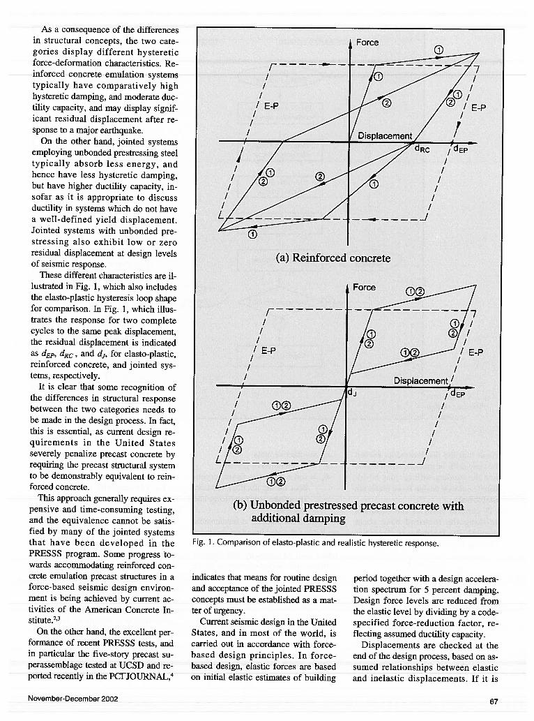
As a consequence of the differencesin structural concepts, the two categories display different hystereticforce-deformation characteristics. Reinforced concrete emulation systemstypically have comparatively highhysteretic damping, and moderate ductility capacity, and may display significant residual displacement after response to a major earthquake.
On the other hand, jointed systemsemploying unbonded prestressing steeltypically absorb less energy, andhence have less hysteretic damping,but have higher ductility capacity, insofar as it is appropriate to discussductility in systems which do not havea well-defined yield displacement.Jointed systems with unbonded prestressing also exhibit low or zeroresidual displacement at design levelsof seismic response.
These different characteristics are illustrated in Fig. 1, which also includesthe elasto-plastic hysteresis ioop shapefor comparison. In Fig. 1, which illustrates the response for two completecycles to the same peak displacement,the residual displacement is indicatedas dEP, dEc, and d, for elasto-plastic,reinforced concrete, and jointed systems, respectively.
It is clear that some recognition ofthe differences in structural responsebetween the two categories needs tobe made in the design process. In fact,this is essential, as current design requirements in the United Statesseverely penalize precast concrete byrequiring the precast structural systemto be demonstrably equivalent to reinforced concrete.
This approach generally requires expensive and time-consuming testing,and the equivalence cannot be satisfied by many of the jointed systemsthat have been developed in thePRESSS program. Some progress towards accommodating reinforced concrete emulation precast structures in aforce-based seismic design environment is being achieved by current activities of the American Concrete Institute.2’3
On the other hand, the excellent performance of recent PRESSS tests, andin particular the five-story precast superassemblage tested at UCSD and reported recently in the PCi JOURNAL,4
indicates that means for routine designand acceptance of the jointed PRESSSconcepts must be established as a matter of urgency.
Current seismic design in the UnitedStates, and in most of the world, iscarried out in accordance with force-based design principles. In force-based design, elastic forces are basedon initial elastic estimates of building
period together with a design acceleration spectrum for 5 percent damping.Design force levels are reduced fromthe elastic level by dividing by a code-specified force-reduction factor, reflecting assumed ductility capacity.
Displacements are checked at theend of the design process, based on assumed relationships between elasticand inelastic displacements. If it is
Fig. 1. Comparison of elasto-plastic and realistic hysteretic response.
November-December 2002 67
FORCE-BASED DESIGN DIRECT DISPLACEMENT-BASED DESIGN
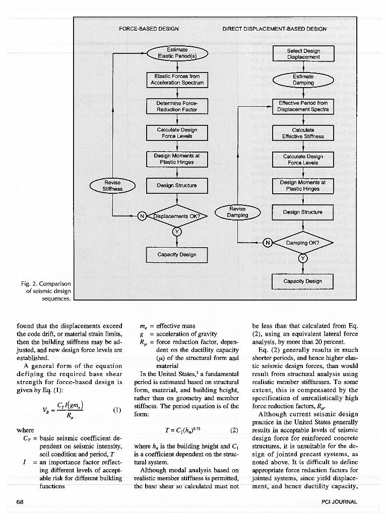
Fig. 2. Comparisonof seismic design
sequences.
found that the displacements exceedthe code drift, or material strain limits,then the building stiffness may be adjusted, and new design force levels are
A general form of the equationdefining the required base shearstrength for force-based design isgiven by Eq. (1):
where
- ci(gmjB R,
CT = basic seismic coefficient dependent on seismic intensity,soil condition and period, T
I = an importance factor reflecting different levels of acceptable risk for different buildingfunctions
me = effective massg = acceleration of gravityR = force reduction factor, depen
dent on the ductility capacity
() of the structural form andmaterial
In the United States,5 a fundamentalperiod is estimated based on structuralform, material, and building height,rather than on geometry and member
(1)stiffness. The period equation is of theform:
T =C1(h)°75
where h is the building height and C1is a coefficient dependent on the structural system.
Although modal analysis based onrealistic member stiffness is permitted,the base shear so calculated must not
be less than that calculated from Eq.(2), using an equivalent lateral forceanalysis, by more than 20 percent.
Eq. (2) generally results in muchcl,nrtr ru.r,nrlQ QnA hnn, herlic.r ,alQc_
tic seismic design forces, than wouldresult from structural analysis usingrealistic member stiffnesses. To someextent, this is compensated by thespecification of unrealistically highforce reduction factors, R.
Although current seismic designpractice in the United States generally
(2) results in acceptable levels of seismicdesign force for reinforced concretestructures, it is unsuitable for the design of jointed precast systems, asnoted above. It is difficult to defineappropriate force reduction factors forjointed systems, since yield displacement, and hence ductility capacity,
68 PCI JOURNAL
F
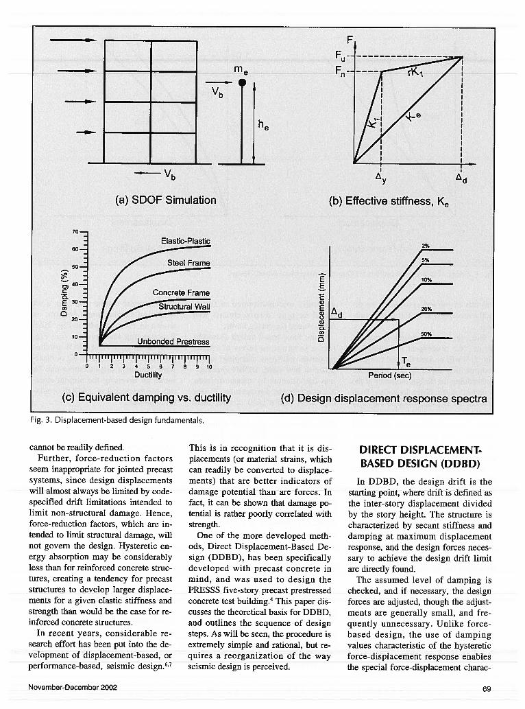
Fig. 3. Displacement-based design fundamentals.
cannot be readily defined.Further, force-reduction factors
seem inappropriate for jointed precastsystems, since design displacementswill almost always be limited by code-specified drift limitations intended tolimit non-structural damage. Hence,force-reduction factors, which are intended to limit structural damage, willnot govern the design. Hysteretic energy absorption may be considerablyless than for reinforced concrete structures, creating a tendency for precaststructures to develop larger displacements for a given elastic stiffness andstrength than would be the case for reinforced concrete structures.
In recent years, considerable research effort has been put into the development of displacement-based, orperformance-based, seismic design.6’7
This is in recognition that it is displacements (or material strains, whichcan readily be converted to displacements) that are better indicators ofdamage potential than are forces. Infact, it can be shown that damage potential is rather poorly correlated withstrength.
One of the more developed methods, Direct Displacement-Based Design (DDBD), has been specificallydeveloped with precast concrete inmind, and was used to design thePRESSS five-story precast prestressedconcrete test building.4This paper discusses the theoretical basis for DDBD,and outlines the sequence of designsteps. As will be seen, the procedure isextremely simple and rational, but requires a reorganization of the wayseismic design is perceived.
DIRECT DISPLACEMENT-BASED DESIGN (DDBD)
In DDBD, the design drift is thestarting point, where drift is defined asthe inter-story displacement dividedby the story height. The structure ischaracterized by secant stiffness anddamping at maximum displacementresponse, and the design forces necessary to achieve the design drift limitare directly found.
The assumed level of damping ischecked, and if necessary, the designforces are adjusted, though the adjustments are generally small, and frequently unnecessary. Unlike force-based design. the use of dampingvalues characteristic of the hystereticforce-displacement response enablesthe special force-displacement charac
me
Vb
he
- Vb
(a) SDOF Simulation
70—
60—
(b) Effective stiffness, Ke
50—
40—C0.E 30—a -
20—
10—
2%
EECa)Ecm,0
0.ci,
U
1111111111 I Ill I Ill Ilj0 1 2 3 4 5 6 7 8 9 10
Ductility
(c) Equivalent damping vs. ductility
Period (sec)
(d) Design displacement response spectra
November-December 2002 69
1 1
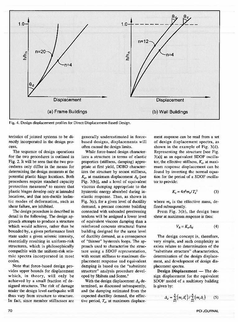
Fig. 4. Design displacement profiles for Direct Displacement-Based Design.
teristics of jointed systems to be directly incorporated in the design process.
The sequence of design operationsfor the two procedures is outlined inFig. 2. It will be seen that the two procedures only differ in the means fordetermining the design moments at thepotential plastic hinge locations. Bothprocedures require standard capacityprotection measures8 to ensure thatplastic hinges develop only at intendedlocations, and that non-ductile inelastic modes of deformation, such asshear failure, are inhibited.
The design procedure is described indetail in the following. The design approach attempts to produce a structurewhich would achieve, rather than bebounded by, a given performance limitstate under a given seismic intensity,essentially resulting in uniform-riskstructures, which is philosophicallycompatible with the uniform-risk seismic spectra incorporated in mostcodes.
Note that force-based design provides upper bounds for displacementwhich, in theory, will only beachieved by a small fraction of designed structures. The risk of damageunder the design level earthquake willthus vary from structure to structure.In fact, since member stiffnesses are
generally underestimated in force-based designs, displacements willoften exceed the design limits.
While force-based design characterizes a structure in terms of elasticproperties (stiffness, damping) appropriate at first yield, DDBD characterizes the structure by secant stiffness,Ke, at maximum displacement Ad [seeFig. 3(b)], and a level of equivalentviscous damping appropriate to thehysteretic energy absorbed during inelastic response. Thus, as shown inFig. 3(c), for a given level of ductilitydemand, a precast concrete buildingconnected with unbonded prestressingtendons will be assigned a lower levelof equivalent viscous damping than areinforced concrete structural framebuilding designed for the same levelof ductility demand, as a consequenceof “thinner” hysteresis loops. The approach used to characterize the structure using a SDOF representation,with secant stiffness to maximum displacement response and equivalentdamping is based on the “substitutestructure” analysis procedure developed by Shibata and Sozen.9
With the design displacement Ad determined, as discussed subsequently,and the damping estimated from theexpected ductility demand, the effective period, Te, at maximum displace-
ment response can be read from a setof design displacement spectra, asshown in the example of Fig. 3(d).Representing the structure [see Fig.3(a)] as an equivalent SDOF oscillator, the effective stiffness, Ke, at maximum response displacement can befound by inverting the normal equation for the period of a SDOF oscillator to provide:
Ke =4t2m/T2 (3)
where me is the effective mass, defined subsequently.
From Fig. 3(b), the design baseshear at maximum response is thus:
VB = KeLld (4)
The design concept is, therefore,very simple, and such complexity asexists relates to determination of the“substitute structure” characteristics,determination of the design displacement, and development of design displacement spectra.
Design Displacement — The design displacement for the equivalentSDOF model of a multistory buildingis given by:
Ad (5)
-c
(a) Frame Buildings
Displacement
(b) Wall Buildings
70 PCI JOURNAL
where m1 and Lid are the story massesand displacements, respectively, at thedesign response level.
This assumes that the inelastic first-mode shape rather than the elasticmode shape should be used to determine the generalized displacement coordinate of the SDOF model. This isconsistent with characterizing thestructure by its secant stiffness tomaximum response. In fact, the inelastic and elastic first-mode shapes aregenerally very similar.’0
Eq. (5) requires knowledge of thedesign displacement profile up theheight of the building, which can bedefined by a critical drift, and a characteristic displacement shape. In mostcases for precast buildings, the criticaldrift will be dictated by code drift limits, as previously discussed.
In general, however, the peak driftcan be expressed as:
0d0y°pc (6)
where the design drift 0d is comprisedof elastic (Op) and plastic (Or) components and must not exceed the codelimit D.
Typical values for O, are within therange of 2 to 2.5 percent. The criticallocation for 0d is likely to be at thelower floors of a frame building. Forwall buildings, the drift based onstrain limitations will be critical at thewall base, but for non-structural elements, the higher drift at the roof levelwill be critical.
Walls with unbonded prestressingwill rarely be governed by materialstrain limitations, and hence it is thedrift at the top floors that will be critical. More research is needed, however, to investigate the influence of ahigher mode response on drifts in theupper stories of frame buildings.
The yield drift depends on structuralgeometry and material sizes. Extensive analyses of structural membersfor conventional or reinforced concrete emulation systems11”2have established that the yield drift and displacement can be estimated from thefollowing member dimensionless yieldcurvatures. These values have beenfound to be relatively insensitive tothe axial load ratio and reinforcementratio within the normal range of these
variables adopted for reinforced concrete design:
Beams (rectangular or flanged):l.7e3, (+1-) 10 percent (7a)
Circular columns:= 2.35e (+1-) 15 percent (7b)
Rectangular columns:= 2.l2r, (+1-) 10 percent (7c)
Rectangular walls:= 2.Or (+1-) 10 percent (7d)
where hb, D, h and l are the depth, ordiameter, of beams, circular columns,rectangular columns, and walls, respectively, and r,,, is the yield strain ofthe flexural reinforcement.
Note that the form of the components of Eq. (7) indicates that the yieldcurvature is independent of strength,and hence strength and stiffness aredirectly proportional. This points to afundamental error in current force-based design, where strength is allocated between members in proportionto their stiffness.
For reinforced concrete frame structures, “yield” drifts may be estimated12by:
(8)hb
where 1b is the bay length (distance between adjacent column centerlines)and hb is the beam depth.
Note that Eq. (8) was developedfrom Eq. (7a), making average allowances for column and joint flexibility, and for member shear deformations. The predictions of Eq. (8) werecompared with results from 43 beam-column test assemblages with different material strengths, proportions andcolumn axial load levels, and wasfound to provide a good estimate ofthe experimental yield drifts, with surprisingly little scatter.’2 Typical yielddrifts from Eq. (8) are in the range of0.006 to 0.012; much larger than isgenerally assumed for reinforced concrete.
Note that the yield drift given byEq. (8) refers to the “corner” of theequivalent bilinear force-displacementresponse, and thus generally exceeds
the true first-yield condition. This definition was adopted because it is directly compatible with assumptionsmade analytically in relating force reduction factors to displacement ductility factors.
When the frames have beams withunbonded prestressing, the elasticstiffness will be much higher than implied by Eqs. (7) and (8), and the yielddrift can be estimated, with sufficientaccuracy for ductility calculations, by:
= 0.0004 (9)
Eq. (9) assumes that the effectiveyield displacement of a prestressedframe is approximately 40 percent ofthat of a reinforced concrete framewith identical member sizes, reinforced with Grade 60 (f = 414 MPa)reinforcement.
Having determined the critical drift,the design displacements, A1, at different stories (i) can be estimated fromcharacteristic displacement profiles atmaximum response based on inelastictime history analysis. The followingequations, though approximate, have:
For building frames:
With n < 4
A = Odh (lOa)
With 4 <n < 20
0.5h1(n —4)]AI=Odhl{1 -
_______
l6h j
With n > 20
A =Ddh(l — 0.5h/h) (lOc)
where n is the number of stories, andh, and h are the heights to the ith storyand roof, respectively.
Note that Eq. (10) implies a displacement profile that changes fromlinear for low-rise frames to parabolicfor frames of twenty stories or more(see Fig. 4a).
For reinforced concrete cantileverwall buildings, the maximum drift occurs at the top of the building (see Fig.4b). From Eq. (7d), assuming a lineardistribution of curvature with height,the elastic yield drift at roof level is:
(lOb)
November-December 2002 71
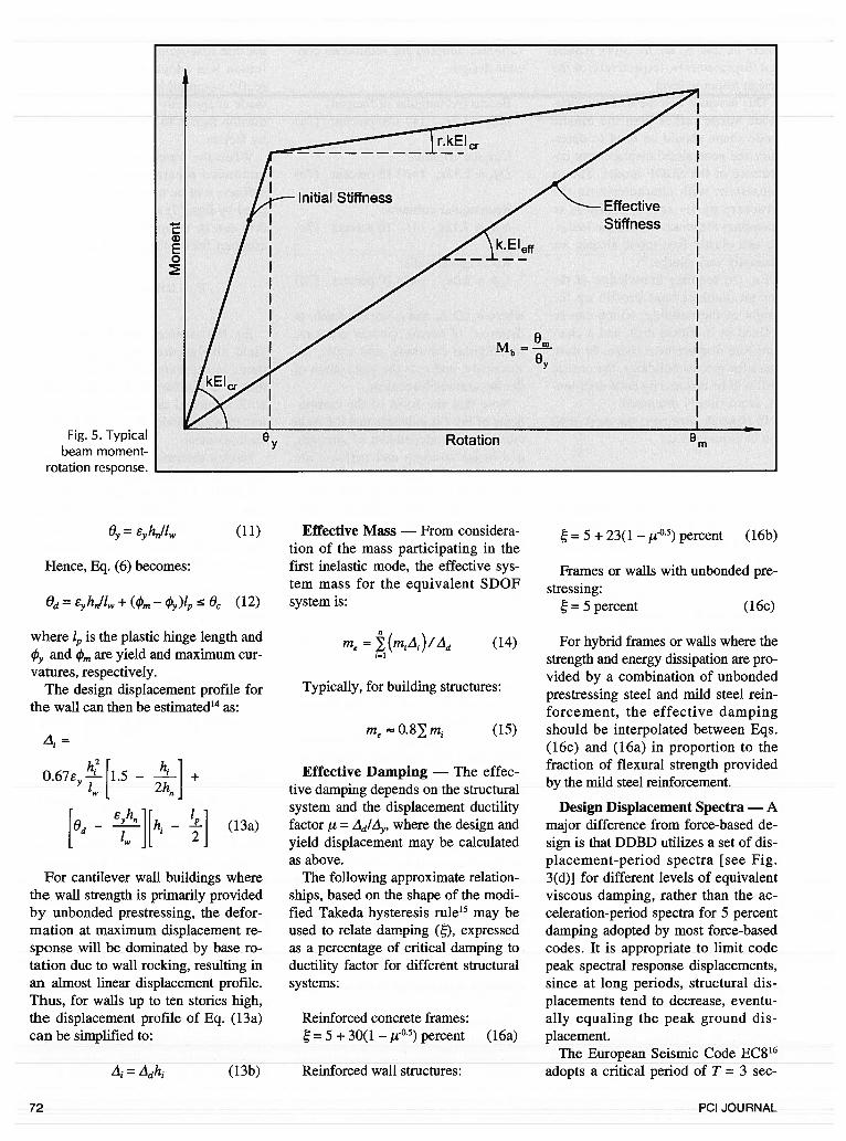
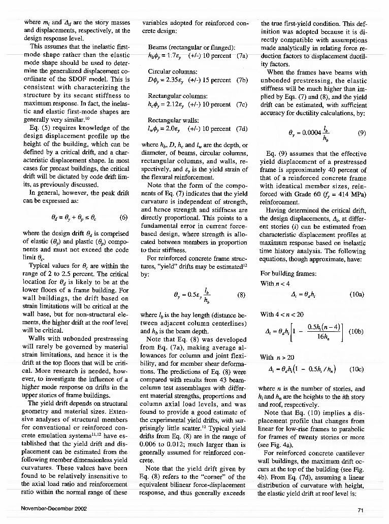
Fig. 5. Typicalbeam moment-
rotation response.
(11)
Hence, Eq. (6) becomes:
= EhIl + (4’m —
O (12)
where 4, is the plastic hinge length and
15y arid m are yield and maximum curvatures, respectively.
The design displacement profile forthe wall can then be estimated’4as:
=
h21O.67ey-!-Il.5 +
2h
[ed—
Byhn][h
—
(13a)
For cantilever wall buildings wherethe wall strength is primarily providedby unbonded prestressing, the deformation at maximum displacement response will be dominated by base rotation due to wail rocking, resulting inan almost linear displacement profile.Thus, for walls up to ten stories high,the displacement profile of Eq. (13a)can be simplified to:
L1=L1dh (13b)
Effective Mass — From consideration of the mass participating in thefirst inelastic mode, the effective system mass for the equivalent SDOFsystem is:
me =
Typically, for building structures:
me=0.8mi (15)
Effective Damping — The effective damping depends on the structuralsystem and the displacement ductilityfactor /L = -d’-1y’ where the design andyield displacement may be calculatedas above.
The following approximate relationships, based on the shape of the modified Takeda hysteresis rule’5 may beused to relate damping (), expressedas a percentage of critical damping toductility factor for different structuralsystems:
Reinforced concrete frames:= 5 + 30(1 — 05) percent (16a)
Reinforced wall structures:
= 5 + 23(1 — O.5) percent (l6b)
Frames or walls with unbonded prestressing:
=5percent (16c)
(14) For hybrid frames or walls where thestrength and energy dissipation are provided by a combination of unbondedprestressing steel and mild steel reinforcement, the effective dampingshould be interpolated between Eqs.(16c) and (16a) in proportion to thefraction of flexural strength providedby the mild steel reinforcement.
Design Displacement Spectra — Amajor difference from force-based design is that DDBD utilizes a set of displacement-period spectra [see Fig.3(d)] for different levels of equivalentviscous damping, rather than the acceleration-period spectra for 5 percentdamping adopted by most force-basedcodes. It is appropriate to limit codepeak spectral response displacements,since at long periods, structural displacements tend to decrease, eventually equaling the peak ground displacement.
The European Seismic Code EC8’6adopts a critical period of T = 3 sec
Stiffness
a)E0
EffectiveStiffness
Mb=Gy
y Rotation
72 PCI JOURNAL
onds above which displacements areconsidered to be independent of periodand equal to the T 3 seconds value.Geotechnical considerations indicatethat the cap period should depend onthe foundation condition, with lowerperiods applying for rock than for softsoil. For alluvial soils, a cap period of4 seconds appears to be appropriatelyconservative.
Displacement spectra should be directly developed for displacement-based design. However, acceptablespectra may be developed from the design acceleration spectrum for 5 percent damping as follows:
A(75) =S(,5)gT2/(4x)
= (T,5) [2+
where S(T5) is the 5 percent spectralresponse acceleration at period T expressed as a fraction of the acceleration due to gravity, g, and A(T5) andA(rf) are the spectral displacements atperiod T for 5 percent and percentdamping, respectively.
Eq. (18) is taken from EC8.’6 Similar equations, differing only slightlyfrom Eq. (18), have been developedby others (e.g., see Reference 17).
Distribution of Base Shear Force
The base shear calculated in accordance with the above procedureshould be vertically distributed basedon the vertical mass and displacementprofiles. Thus:
F=VB(m/A,)/2(m1.l) (19)
Similarity with force-based designwill immediately be apparent. The difference is that the design displacementprofile, rather than a height-proportional displacement (which in effectassumes a linear distribution of elasticdisplacements with height), isadopted.
Analysis for MemberDesign Actions
Since Direct Displacement BasedDesign considers the structural condi
tion at maximum displacement response, the structural analysis underthe design forces defined by Eq. (19)should use member stiffnesses appropriate to member condition at maximum response. Thus, in a frame building designed for beam hinging, thebeam members will be subjected to inelastic actions, and the effective stiffness should be reduced to reflect this.
Refening to the beam moment-rotation response of Fig. 5, the appropriatebeam stiffness will be:
EIeff EIcr[l + r(!lb— 1)]’!b (20)
where= expected beam rotation duc
tility demandEI = cracked section stiffness at
effective yieldr = ratio of post-yield to pre
yield stiffnessAnalyses’3have shown that member
forces are not particularly sensitive tothe level of stiffness assumed, andthus it is acceptable to assume EleffEI,Jii7, where is the frame designductility. Since the columns will bedesigned to remain in the elastic(cracked) range of response, it is appropriate to use the cracked-section
stiffness for these members. An exception occurs at the base of thecolumns, where plastic hinges can beexpected to form.
It has been found7 that the most effective way to model this is to modelthe base of the columns as hinges, andapply a base-resisting moment, Mb, tothe hinge, while representing the column by the cracked-section stiffness.This is represented in Fig. 6, wheredifferent moments are applied at thebases of the three columns, in recognition of the influence of the differentaxial forces on the column strengths.
The values of the moment applied atthe column base are to some extent adesign choice, since analysis of thestructure under the lateral force vectortogether with the chosen column basemoments will ensure a statically admissible equilibrium solution for design moments at all parts of the frame.If the columns are precast, the designbase moments will reflect the capacityof the chosen connection detail, withdue consideration of the axial forcefrom gravity and seismic loading.
Distribution of design forces between parallel walls should be in proportion to l where 1 is the walllength. This essentially results in
F
F1
\‘bt I/-Icr,
/I =1C cr
\-I I’!-’Cr’/b
(17)
(18)
IC=
M1 IN M3M.., ..
Fig. 6. Analysis of frame building.
h1
November-December 2002 73
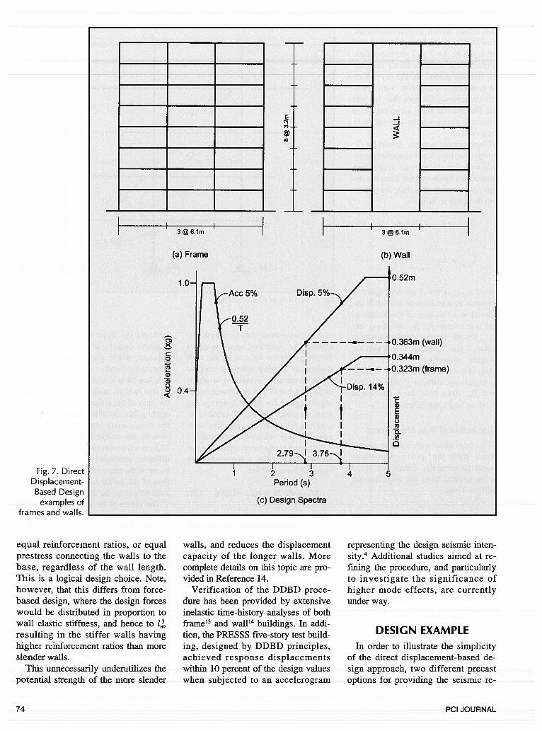
Fig. 7. DirectDisplacement-Based Design
examples offrames and walls.
equal reinforcement ratios, or equalprestress connecting the walls to thebase, regardless of the wall length.This is a logical design choice. Note,however, that this differs from force-based design, where the design forceswould be distributed in proportion towall elastic stiffness, and hence to lresulting in the stiffer walls havinghigher reinforcement ratios than moreslender walls.
This unnecessarily underutilizes thepotential strength of the more slender
walls, and reduces the displacementcapacity of the longer walls. Morecomplete details on this topic are provided in Reference 14.
Verification of the DDBD procedure has been provided by extensiveinelastic time-history analyses of bothframe’3 and wall’4 buildings. In addition, the PRESSS five-story test building, designed by DDBD principles,achieved response displacementswithin 10 percent of the design valueswhen subjected to an accelerogram
DESIGN EXAMPLEIn order to illustrate the simplicity
of the direct displacement-based design approach, two different precastoptions for providing the seismic re
representing the design seismic intensity.4 Additional studies aimed at refining the procedure, and particularlyto investigate the significance ofhigher mode effects, are currentlyunder way.
74 PCI JOURNAL
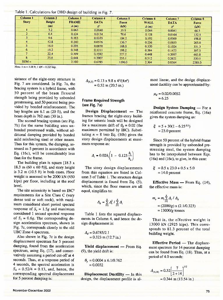
Table 1. Calculations for DBD design of building in Fig. 7.Column 1 Column 2 Column 3 Column 4 S Column 6 Column 7 Column 8
Story Height FRAME DATA Force WALL DATA Force(m) A (m) A2 (kN) A (m) A2 (kN)
1 - 3.2 - 0.063- 0.0040 , 35 9 0.064 0.0041 - 66.3
2 6.4 0.124 ft0154 70.6 0.128 0.0164 i32.5 —
3 9.6 0.183 O.O333f . 104.2 198.84 12.8 . 0.240 0.0576 136.7 0.256 . 0.0655
.,
265.016.0 0.295 0.0870 168.0 0.320 0.1024 333
6 19.2 0.348 0.1211 198.2 0.384 0.1475 397.57J 22.4 0.39 0.1592 227.2 0.448 — 0.2007 463.88 25.6 0.448 0.2007 255.1 0.512 . 0.2621 530.0
SUM= 2.100 0.6785 1196.0 2.304 0.8364 2385.0
Note: 1 m = 3.28 ft; 1 kN 0.225 kip.
sistance of the eight-story structure inFig. 7 are considered. In Fig. 7a, thebracing system is a hybrid frame, with50 percent of the beam flexuralstrength being provided by unbondedprestressing, and 50 percent being provided by bonded reinforcement. Thebay lengths are 6.1 m (20 ft), and thebeam depth is 762 mm (30 in.).
The second bracing system (see Fig.7b) for the same building uses unbonded prestressed walls, without additional damping provided by bondedmild reinforcing steel or other means.Thus for this system, the damping, assessed as 5 percent in accordance withEq. (16c), will be considerably lessthan for the frame.
The building plan is square [18.3 x18.3 m (60 x 60 ft)], and story heightis 3.2 m (10.5 ft) in both cases. Floorweight is assessed to be 2000 kN (450kips) per floor, including at the rooflevel.
The site seismicity is based on IBC5requirements for a Site Class C (verydense soil or soft rock), with maximum considered short period spectralresponse of S2 = 1.5g and maximumconsidered 1 second spectral responseof S1 = 0.6g. The corresponding design acceleration spectrum, shown inFig. 7c, corresponds closely to the oldUBC Zone 4 spectrum.
Also shown in Fig. 7c is the designdisplacement spectrum for 5 percentdamping, found from the accelerationspectrum, using Eq. (17), and conservatively assuming a period cut-off at 4seconds. Thus, at a response period of4 seconds, the spectral acceleration isS4 = 0.52/4 = 0.13, and, hence, thecorresponding spectral displacementfor 5 percent damping is:
A(45) = 0.13 x 9.8 x 42/(4.2)
= 0.52 m (20.5 in.)
Frame Required Strength(see Fig. 7a)
Design Displacement — Theframes bracing the eight-story building for seismic loads will be designedfor a maximum drift of O 0.02 (themaximum permitted by IBC). Substituting n = 8 into Eq. (lOb) gives thestory design displacements at maximum response as:
A =0.02h(1 - 0.l25
The story design displacementsfrom this equation are listed in Column 3 of Table 1. The structure designdisplacement is found from Eq. (5),which, since the floor masses are allequal, simplifies to:
Ad=
/
Table 1 lists the squared displacements in Column 4, and hence the design displacement is:
= 0.6785/2.1= 0.323 m (12.7 in.)
Yield displacement — From Eq.(9), the yield drift is:
= 0.0004 x 6. 1/0.762=0.0032
Displacement Ductility — In thisdesign, the displacement profile is al
most linear, and the design displacement ductility can be approximated by:
Pd = 0.02/0.0032= 6.25
Design System Damping — For areinforced concrete frame, Eq. (1 6a)gives the system damping as:
= 5 + 30(1 6.25°)= 23.0 percent
Since 50 percent of the hybrid framestrength is provided by unbonded prestressing steel, the system dampinghas to be interpolated between Eqs.(16a) and (16c), to give, in this case:
=0.5x23.0+0.5x5.0= 14.0 percent
Effective Mass — From Eq. (14),the effective mass is:
me =mI4I1d
= (2000/g) x (2.1/0.323)= 13000/g tonnes
That is, the effective weight is13000 kN (2925 kips). This corresponds to 81.3 percent of the totalbuilding weight.
Effective Period The displacement spectrum for 14 percent dampingcan be found from Eq. (18). Thus, at aperiod of 4.0 seconds:
112
A44 =0.522+14
= 0.344 m (13.54 in.)
November-December 2002 75
The displacement spectrum for 14percent damping is also shown in Fig.7c. As with the 5 percent dampingspectrum, it is linearly proportional toa period above T = 0.523 second.Thus, the period corresponding to thedesign displacement of 0.3 23 m can befound by proportion as:
Te = 4.0 X (0.323/0.344)= 3.76 seconds
The procedure is also shown graphically in Fig. 7c by the dashed lines.
Effective Stiffness — From Eq. (3),the effective secant stiffness at maximum displacement response is:
Ke = 4(13000Ig)I3.762=3704kN/m
where the acceleration of gravity wastaken as g = 9.8
Design Base Shear Force — Finally, from Eq. (4), the design baseshear force at maximum displacementresponse is:
VB= 3704x0.323= 1196 kN (269 kips) = 7.5 per
cent of building weight
This base shear is distributed between the floors in accordance withEq. (19), and the results are listed inColumn 5 of Table 1. The structurecan now be analyzed under theseforces to determine the required design moments at maximum displacement response, using the proceduresoutlined above.
Note that the base shear is the totalrequired for the building, and wouldbe divided between the number offrames participating in seismic resistance. In this case, a peripheral seismic frame system is envisaged, withinternal gravity frames. Hence, the required base shear would be 598 kN(134 kips) per frame.
Note that in this case the design effective displacement, and the yielddisplacement were known before thedesign started. As a consequence, thedamping of 14 percent calculatedabove is the final value, independentof strength, and no revision to the design, as indicated in Fig. 2, is needed.
In this case, a revision would onlyhave been needed if the initial beamsize was altered after the design baseshear was determined. If the beam sizehad been altered, the yield drift, andhence the ductility and damping would
hnce’r1 rpriiiirinc,
cycle to converge the design process.
Wall Required Strength(see Fig. 7b)
Design Displacement — As withthe frame, the wall is designed for amaximum drift of 0.02. In accordancewith Eq. (13b), the design displacement profile is linear, and the designfloor level displacements are given inColumn 6 of Table 1. The squared displacements are listed in Column 7 ofTable 1. Hence, the design displacement is:
= 0.8364/2.304= 0.363 m (14.3 in.)
Yield Displacement —
needed)(Not
Design System Damping — 5 percent, as above.
Effective Mass — From Eq. (14):
me = (2000/g) x (2.304/0.363)= 12694/g tonnes (79.3 percent
of total weight)
Effective Period — Using the 5 percent displacement spectrum of Fig. 7c,
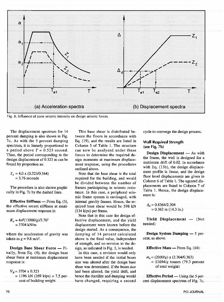
Fig. 8. Influence of zone seismic intensity on design seismic forces.
76 PCI JOURNAL
by linear proportion the effective period is:
Te = 4.0 X (0.363/0.520)2.79 seconds
This is also shown graphically inFig. 7c.
Effective Stiffness — From Eq. (3):
Ke =4.7t2(1269419.8)12.792= 6569 kN/m
Design Base Shear Force — FromEq.(4):
VB= 6569x 0.363= 2385 kN (536 kips) = 15 per
cent of building weight
The floor forces corresponding tothis base shear and Eq. (19) are listedas Column 8 of Table 1.
Note that the base shear force forthe wall is twice that for the frame.This is because there is no additional(hysteretic) damping for the wall solution, and hence, higher strength is required to limit the displacement to thedesign values.
If the strength of the wall had beenprovided by a combination of unbonded prestressing and some energydissipation system, as was the case forthe PRESSS five-story building, thedesign base shear would have beensimilar to that of the frame solution. Infact, the solution for the wall design ofthe PRESSS test building used parallelvertical wall elements connected withrolling plate energy dissipators.
These dissipated more energy thanimplied by interpolation between Eqs.(l6a) and (16c), resulting in a system
damping of close to 20 percent. Usingthis value, the design base shearstrength for the wall direction could bereduced below that required for theframe.
CONCLUDING REMARKSDirect displacement-based seismic
design is a simple procedure for determining the required base shearstrength, and hence the critical designbending moments of potential plastichinges, to ensure that a precast (orconventional structural system) structure responds at the design drift limit.The special characteristics of precastconcrete systems, with high ductilityand drift capacity, but in some casesreduced damping capacity, can be directly incorporated into the designprocedure, which is no more complexthan the Equivalent Lateral Force procedure currently specified in American codes.
Use of direct displacement-baseddesign will result in more consistentdesigns than force-based design criteria, and will generally result in reduced design forces, particularly forregions of moderate seismic intensity,such as the Central and Eastern UnitedStates. This is because examination7ofthe fundamental basis of displacement-based design shows that the required strength is proportional to thesquare of seismic intensity, whereascurrent force-based design specifiesstrength directly proportional to zoneintensity.
This apparent anomaly can be understood with reference to Fig. 8,which compares acceleration and displacement spectra for two levels of
seismic intensity, Z1 and Z2. It is assumed that the spectral shapes for thetwo levels of intensity are the same.For force-based design, assuming thatbuildings designed for the two levelsof intensity have the same membersizes, the elastic periods will be thesame, as will the force-reduction factors, and hence the base shears forsimilar buildings in the two zones willbe directly proportional to the zone intensity. Thus:
Vb2 = Vbl(Z2!Zl) (21)
With DDBD, the design displacements for two similar buildings builtin Zones 1 and 2 will be the same (seeFig. 8b), and hence the effective periods T1 and T2 at peak displacement response will be related by:
T2 =T1(Z1/Z2) (22)
But from Eqs. (3) and (4), it is seenthat the base shear force is inverselyproportional to the square of the effective period, and hence:
Vb2 Vbl(Z2/Zl)2 (23)
The difference between the resultsof Eqs. (21) and (23) represents amajor outcome of the difference in approach between force-based and displacement-based design.
It is emphasized that, as with force-based design, an integral part ofDDBD is the use of capacity designprinciples8 to ensure that unintendedplastic hinges cannot form, and thatenergy is dissipated by ductile flexuralaction, rather than by non-ductile inelastic shear action.
November-December 2002 77

REFERENCES
1. Priestley, M. J. N., “The PRESSS Program — Current Statusand Proposed Plans for Phase III,” PCI JOURNAL, V. 41, No.2, March-April 1996, pp. 22-40.
2. ACI Innovation Task Group 1 and Collaborators, “AcceptanceCriteria for Moment Frames Based on Structural Testing (ACIITG/T 1.1-01),” American Concrete Institute, FarmingtonHills, MI, 2001.
3. ACT Innovation Task Group 1 and Collaborators, “Special Hybrid Moment Frames Composed of Discretely Jointed Precastand Post-Tensioned Concrete Members (ACT T 1 .2-XX) andCommentary (T1.2R-XX),” ACI Structural Journal, V. 98,No. 5, September-October 2001, pp. 77 1-784.
4. Priestley, M. J. N., Sritharan, S., Conley, J. R., and Pampanin,S., “Preliminary Results and Conclusions From the PRESSSFive-Story Precast Concrete Test Building,” PCT JOURNAL,V. 44, No. 6, November-December 1999, pp. 42-67.
5. TCC, IBC 2000 International Building Code, InternationalCode Council, Falls Church, VA, 2000.
6. Fajfar, P., and Krawinkler, H. (Editors), “Seismic DesignMethodologies for the Next Generation of Building Codes,”Proceedings of an International Conference at Bled, Slovenia,A. A. Bailcema, RotterdamlBrookfield, 1997, 411 pp.
7. Priestley, M. J. N., “Performance Based Seismic Design,”Keynote Address, 12th World Conference on Earthquake Engineering, Auckland, New Zealand, January 2000.
8. Paulay, T., and Priestley, M. J. N., Seismic Design of Reinforced Concrete and Masonry Buildings, John Wiley & Sons,New York, NY, 1992.
9. Shibata, A., and Sozen, M., “Substitute Structure Method forSeismic Design in Reinforced Concrete,” Journal of Structural
Engineering, American Society of Civil Engineers, V. 102,No. 12, pp. 3548-3566.
10. Sozen, M. A., “Review of Earthquake Response of R/C Buildings with a View to Drift Control,” State-of-the-Art in Earthquake Engineering, 0. Ergunay and M. Erdik (Editors),Ankara, Turkey, 1981, pp. 383-418.
11. Priestley, M. J. N., and Kowalsky, M. J., “Aspects of Drift andDuctility Capacity of Cantilever Structural Walls,” Bulletin,NZ Society for Earthquake Engineering, V. 31, No. 2, June1998.
12. Priestley, M. J. N., “Brief Comments on Elastic Flexibility ofReinforced Concrete Frames, and Significance to Seismic Design,” Bulletin, NZ Society for Earthquake Engineering, V. 31,No. 4, December 1998.
13. Loeding, S., Kowalsky, M. J., and Priestley, M. J. N., “DirectDisplacement-Based Design of Reinforced Concrete FrameBuildings,” Report SSRP 98/08, University of California, SanDiego, CA, 1998.
14. Priestley, M. J. N., and Kowalsky, M. J., “Direct Displacement-Based Design of Concrete Buildings,” Bulletin, NZ Society for Earthquake Engineering, V. 33, No. 4, December 2000.
15. Otani, S., “Hysteresis Models for Reinforced Concrete forEarthquake Response Analysis,” Jour,wl, Faculty of Engineering, University of Tokyo, Tokyo, Japan, V. XXXVI, No. 2,1981, pp. 125-159.
16. EC8, Eurocode (2000), Design Provisions for Earthquake Resistance of Structures, Lausanne, Switzerland.
17. SEAOC Seismology Committee, SEAOC Recommended LateralForce Requirements and Commentary, 7th Edition, StructuralEngineers Association of California, Sacramento, CA, 1999.
78 PCI JOURNAL

APPENDIX A — NOTATIONC1 = coefficient dependent on structural systemC- = basic seismic coefficient dependent on seismic
intensity, soil condition and period TD = diameter of circular columndEp = residual displacement for elasto-plastic systemdRc = residual displacement for reinforced concrete
systemd = residual displacement for jointed systemE = Young’s modulus of elasticityF inertia force at ig = acceleration of gravityhb = depth of beam
= height to i th story= building height= depth of rectangular column
I = importance factor reflecting different levels ofacceptable risk for different building functions
= moment of inertia of cracked section at effectiveyield
‘eff = moment of inertia adjusted for ductilityKe = effective stiffness at maximum displacement
= depth of walltb = bay length1,, = plastic hinge lengthm = effective massm1 = story massn = number of storiesr , = ratio of post-yield to pre-yield stiffnessR = force reduction factor, dependent on ductility ca
pacity (ii) of structural form and materialS4 spectral acceleration at a response period of 4
secondsS(T5) = 5 percent spectral response acceleration at period
TT period
Tç = effective period at maximum displacementT1 = effective period at peak displacement response
for building in specified seismicity Zone IT2 = effective period at peak displacement response
for building in specified seismicity Zone 2VB = required base shear strengthVbl required base shear strength for force based de
sign in specified seismicity Zone 1Vb2 = required base shear strength in specified seismic
ity Zone 1= level of seismicity, Zone 1= level of seismicity, Zone 2= design displacement of SDOF structure= design displacement at story i= yield displacement= spectral displacement at period T for 5 percent
damping= spectral displacement at period T for percent
damping4(4,5) = spectral displacement with a period of 4 seconds
for 5 percent damping(4,14) = spectral displacement with a period of 4 seconds
for 14 percent dampingyield strain of flexural reinforcement
lm = maximum curvatureyield curvature
= ductility capacitylb = expected beam rotation ductility demand
= frame design ductility= 3.14159= code limit drift
0d = design drift= plastic component drift= elastic component drift= percentage of critical damping
z1z2
I-liLly
4(T,5)
November-December 2002 79