Direct-acting 2/2- or 3/2-way pivoted armature valve · Oxydizing acids and substances, hot oils...
12
0330 p. 1/12 Technical data Available housing materials Brass Stainless steel (1.4401) PP (Polypropylene) PVDF (Polyvinylfluoride) Port connection G 1/4; NPT 1/4; (RC 1/4 and G 1/8 on request) Seal material EDPM / FKM / FFKM / NBR Medium for NBR EPDM for FKM for FFKM Neutral medium such as compressed air, town gas, water, hydraulic oil, oils and fats without additives, oxygen Alkalis, acids to medium concentrations, alkaline washing and bleaching lyes Oxydizing acids and substances, hot oils with additives, salt solutions, waste gases, oxygen aggressive mediums, hot air, hot oils All Materials - For more exact info. please refer to our chemical resistance chart Medium temperature for body material brass or stainless steel NBR 0 to +80 °C EPDM -30 to +90 °C FKM 0 to +90 °C FFKM +5 to +90 °C Medium temperature for body material PP or PVDF NBR 0 to +80 °C EPDM -30 to +80 °C FKM 0 to +80 °C FFKM +5 to +80 °C Viscosity Max. 37mm²/s Ambient temperature max. +55 °C Voltages 24V 50Hz; 110V 50Hz; 230V 50Hz; 120V 60Hz; 240V 60Hz; 12V DC; 24V DC; (further voltages on request) Voltage tolerance +/- 10% Duty cycle for brass and stainless steel. 100% Duty cycle for PP and PVDF 40% ED (60% intermittent operation) in 30min for 8W version 100% ED for 5W version continued The 0330 valve is a direct-acting, media-sep- arated pivoted armature valve. It is available in 3/2- and 2/2-way versions. As a 3/2-way ver- sion, it can be used as a distributor or mixing valve. Various diaphragm material combinations and methods of operation are available de- pending on the application. The standard brass housing satisfies all European drinking water requirements. Stainless steel (316), PVDF, and polypropylene housing versions complete the offering. The solenoid coils are moulded with a chemically resistant epoxy. The 0330 is equipped with manual override for commission- ing and testing. For reduced energy require- ments all coils can be delivered with electronic power reduction or as an impulse version. The switching status can be indicated with posi- tion feedback as a binary or NAMUR signal. In combination with a plug in accordance with DIN EN 17301-803 Form A, the valves satisfy protection class IP65/67 – in combination with a stainless steel or plastic housing NEMA 250 Cat. 4X. • Direct-acting, media-separated valve with diameter of up to DN 5 • Maintenance-free pivoted armature technology • Vibration-proof, block screwed coil system • Suitable for aggressive alkaline and acidic solutions • Service-friendly, robust manual operation • Explosion proof versions Content: Standard version Technical data p. 1 Additional options p. 4 Dimensions & Pin Assignment p. 5 Ordering chart p. 6 Explosion proof version Technical data p. 7 Additional options p. 9 Dimensions & Pin Assignment p. 10 Ordering chart p. 11 Direct-acting 2/2- or 3/2-way pivoted armature valve
Transcript of Direct-acting 2/2- or 3/2-way pivoted armature valve · Oxydizing acids and substances, hot oils...

0330
p. 1/12
Technical dataAvailable housing materials Brass
Stainless steel (1.4401)PP (Polypropylene)PVDF (Polyvinylfluoride)
Port connection
G 1/4; NPT 1/4; (RC 1/4 and G 1/8 on request)
Seal material EDPM / FKM / FFKM / NBRMedium for NBR
EPDM
for FKM
for FFKM
Neutral medium such as compressed air, town gas, water, hydraulic oil, oils and fats without additives, oxygenAlkalis, acids to medium concentrations, alkaline washing and bleaching lyesOxydizing acids and substances, hot oils with additives, salt solutions, waste gases, oxygenaggressive mediums, hot air, hot oils
All Materials - For more exact info. please refer to our chemical resistance chartMedium temperaturefor body materialbrass or stainless steel
NBR 0 to +80 °CEPDM -30 to +90 °CFKM 0 to +90 °CFFKM +5 to +90 °C
Medium temperaturefor body materialPP or PVDF
NBR 0 to +80 °CEPDM -30 to +80 °CFKM 0 to +80 °CFFKM +5 to +80 °C
Viscosity Max. 37mm²/sAmbient temperature max. +55 °CVoltages 24V 50Hz; 110V 50Hz; 230V 50Hz; 120V 60Hz;
240V 60Hz; 12V DC; 24V DC;(further voltages on request)
Voltage tolerance +/- 10%Duty cycle for brass and stainless steel.
100%
Duty cycle for PP and PVDF 40% ED (60% intermittent operation) in 30min for 8W version 100% ED for 5W version
continued
The 0330 valve is a direct-acting, media-sep-arated pivoted armature valve. It is available in 3/2- and 2/2-way versions. As a 3/2-way ver-sion, it can be used as a distributor or mixing valve. Various diaphragm material combinations and methods of operation are available de-pending on the application. The standard brass housing satisfies all European drinking water requirements. Stainless steel (316), PVDF, and polypropylene housing versions complete the offering. The solenoid coils are moulded with a chemically resistant epoxy. The 0330 is equipped with manual override for commission-ing and testing. For reduced energy require-ments all coils can be delivered with electronic power reduction or as an impulse version. The switching status can be indicated with posi-tion feedback as a binary or NAMUR signal. In combination with a plug in accordance with DIN EN 17301-803 Form A, the valves satisfy protection class IP65/67 – in combination with a stainless steel or plastic housing NEMA 250 Cat. 4X.
• Direct-acting, media-separated valve with diameter of up to DN 5
• Maintenance-free pivoted armature technology
• Vibration-proof, block screwed coil system
• Suitable for aggressive alkaline and acidic solutions
• Service-friendly, robust manual operation
• Explosion proof versions
Content:Standard version Technical data p. 1 Additional options p. 4 Dimensions & Pin Assignment p. 5 Ordering chart p. 6
Explosion proof version Technical data p. 7 Additional options p. 9 Dimensions & Pin Assignment p. 10 Ordering chart p. 11
Direct-acting 2/2- or 3/2-way pivoted armature valve

0330
p. 2/12
Circuit function
A 2/2 way direct-acting solenoid valve, normally closed
B 2/2 way direct-acting solenoid valve, normally open
C 3/2 way direct-acting solenoid valve, normally closed
D 3/2 way direct-acting solenoid valve, normally open
E 3/2 way mixing solenoid valve
F 3/2 way direct-acting, distribution solenoid valve
T 3/2 way direct-acting solenoid valve, flow direction optional
2 (A)
1 (P)
2 (B)
1 (P)
2(A)
1(P) 3(R)
12
2(B)
1(P) 3(R)
10
2(A)
1(P1) 3(P2)
4(A) 2(B)
1(P)
NC NO
Response times [ms]:Measured at valve outlet at 6 bar and +20 °COpening: Pressure rise 0 to 90%, Closing: Pressure drop 100 to 10%
Pressure range and flow rate for metal body
Circuit function DN Kv value water [m³/h]: Standard 1) Impulse 2)
DC AC [50 or 60Hz]
Pressure range 4) [bar]
Vacuum 3)
Pressure range 4) [bar]Pressure range 4) [bar]
A / B / C / D / F 2.0 0.08 0.11 0 - 16 5) -0.98 - 10 0 - 16 5)
3.0 0.14 0.18 0 - 10 -0.98 - 6 0 - 104.0 0.17 0.23 0 - 5 -0.98 - 3 0 - 55.0 0.29 0.29 0 - 2.5 -0.98 - 1 0 - 2.5
E 2.0 0.08 0.11 0 - 10 -0.98 - 8 0 - 103.0 0.14 0.18 0 - 6 -0.98 - 5 0 - 64.0 0.17 0.23 0 - 3 -0.98 - 2.5 0 - 35.0 0.29 0.29 0 - 1.5 -0.98 - 1 0 - 1
T 2.0 0.08 0.11 0 - 12 -0.98 - 8 0 - 103.0 0.14 0.18 0 - 8 -0.98 - 5 0 - 64.0 0.17 0.23 0 - 4 -0.98 - 2.5 0 - 55.0 0.29 0.29 0 - 2.5 -0.98 - 1 -
Pressure range and flow rate for plastic body
Circuit function DN Kv value water
[m3/h]6)
Standard 1) Impulse 2)
Pressure range 4) [bar] AC [50 or 60Hz]
Pressure range 4)
[bar] DCVacuumPressure range 4) [bar]
Pressure range 4) [bar]
A / B / C / D / F 2.0 0.13 0 - 16 5) 0 - 12 -0.98 - 10 0 - 123.0 0.25 0 - 10 0 - 8 -0.98 - 6 0 - 84.0 0.30 0 - 5 0 - 4 -0.98 - 3 0 - 45.0 0.40 0 - 4.5 0 - 3 -0.98 - 1 0 - 3
E / T 2.0 0.13 0 - 10 0 - 7 -0.98 - 7 0 - 73.0 0.25 0 - 6 0 - 4 -0.98 - 5 0 - 44.0 0.30 0 - 3 0 - 2 -0.98 - 2.5 0 - 2
1) Rated power consumtion 8W2) Inrush power 11W3) Vacuum possible for all seal materials4) Pressure values [bar] with respect to atmospheric pressure5) For seal material FKM and FFKM the max. mediums pressure is 12 bar6) At frequency DC the KV value is reduced till 10% to fulfil the function
Technical data (continued)
Electrical connection Pin terminal acc. to DIN EN 175301-803 Form A for cable pug Type 2508/2509(also on request with moulded cable or terminal box)
Protection class IP65 with Cable PlugCoil insulation class HInstallation As required, preferably with actuator uprightWeight [kg] with metal body with plastic hausing
0.470.40
Standard power consumption Frequency AC Frequency DCInrush [VA] Hold [VA] Operation [W] Cold [W] Warm [W]30 15 8 11 8
Impulse (inrush winding)Frequency AC Frequency DCHold [VA] Operation [W] Cold [W] Warm [W]
20 11 11 8
Response timesOrifice [mm] Frequency AC Frequency DC
Opening [ms] Closing [ms] Opening [ms] Closing [ms]
2-4 8-15 8-15 10-20 10-20
0330
p. 3/12
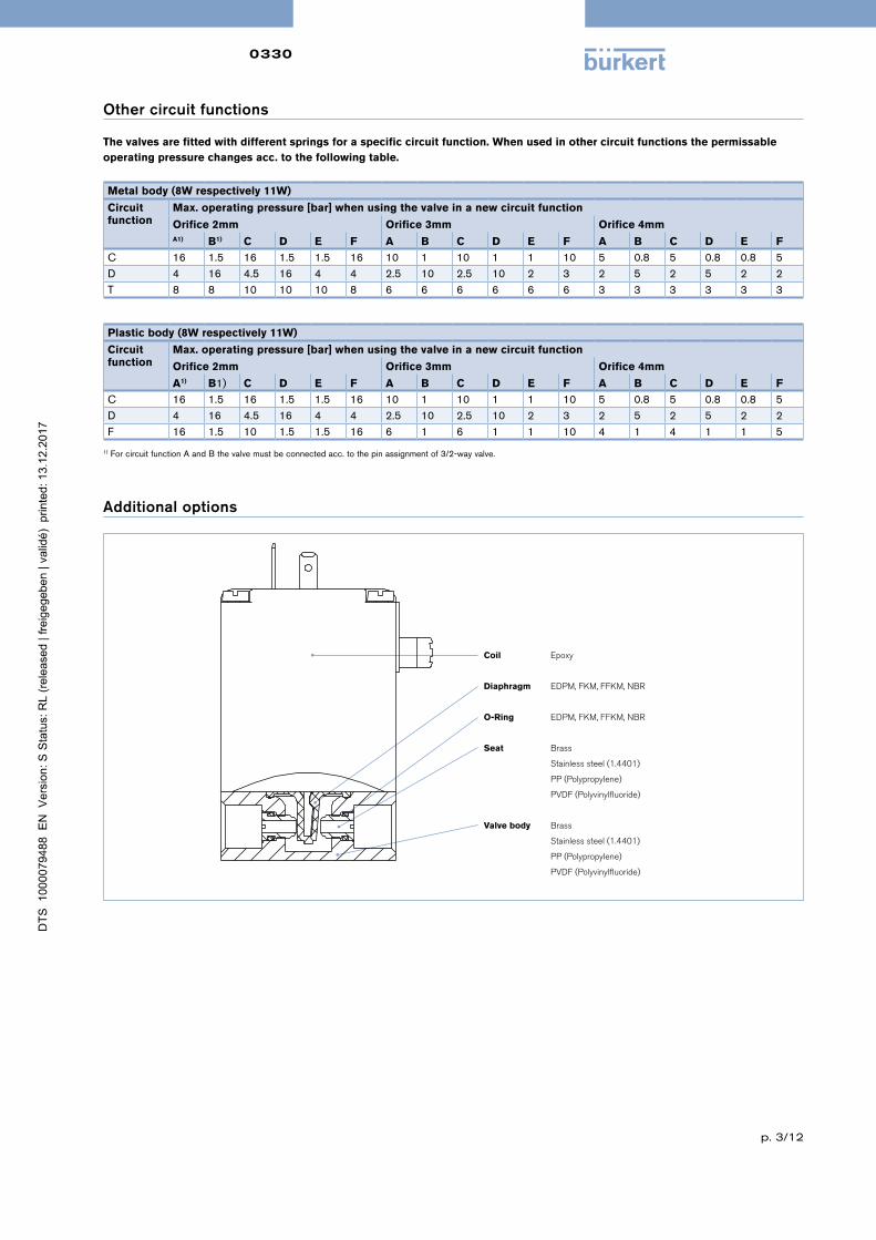
Other circuit functions
The valves are fitted with different springs for a specific circuit function. When used in other circuit functions the permissable operating pressure changes acc. to the following table.
Metal body (8W respectively 11W)
Circuitfunction
Max. operating pressure [bar] when using the valve in a new circuit function
Orifice 2mm Orifice 3mm Orifice 4mmA1) B1) C D E F A B C D E F A B C D E F
C 16 1.5 16 1.5 1.5 16 10 1 10 1 1 10 5 0.8 5 0.8 0.8 5D 4 16 4.5 16 4 4 2.5 10 2.5 10 2 3 2 5 2 5 2 2T 8 8 10 10 10 8 6 6 6 6 6 6 3 3 3 3 3 3
Plastic body (8W respectively 11W)
Circuit function
Max. operating pressure [bar] when using the valve in a new circuit function
Orifice 2mm Orifice 3mm Orifice 4mm
A1) B1) C D E F A B C D E F A B C D E F
C 16 1.5 16 1.5 1.5 16 10 1 10 1 1 10 5 0.8 5 0.8 0.8 5D 4 16 4.5 16 4 4 2.5 10 2.5 10 2 3 2 5 2 5 2 2F 16 1.5 10 1.5 1.5 16 6 1 6 1 1 10 4 1 4 1 1 5
1) For circuit function A and B the valve must be connected acc. to the pin assignment of 3/2-way valve.
Additional options
Coil Epoxy
Diaphragm EDPM, FKM, FFKM, NBR
O-Ring EDPM, FKM, FFKM, NBR
Seat Brass
Stainless steel (1.4401)
PP (Polypropylene)
PVDF (Polyvinylfluoride)
Valve body Brass
Stainless steel (1.4401)
PP (Polypropylene)
PVDF (Polyvinylfluoride)

0330 Ex
p. 4/12
Additional options
Option Variable Code
Description
Impulse version CF02 Bistable magnetic system with inrush and drop-off coil;Continuous opera-tion or operation with short current pulses (min. 150 ms) possible
Oxygen versions NL02 Suitable for applications with oxygen (non-metal materials that are in contact with the medium, are tested and approved according to BAM)
Increased purity requirements e.g. oil, grease and silicone-free
NL50/NL05 Wetted parts are specially cleaned and packaged in accordance with the valves
Increased tightness requirements PCxx Standard units are tested at 10-2 mbar x l / sec; feasible up to 106 mbarElectrical feedback LF02 / LF03 See Type 1060High-power electronics CZ05 Inrush power 60 W, nominal holding current 3 W; with plastic versions
100% ED is now feasibleVacuum version NA02 Suitable for vacuums up to -0.98barIncreased purity and tightness requirements NA03 Wetted parts are specially cleaned and leak tested to 10-4 mbar x l/secIncreased purity and tightness requirements and vacuum version
NA01 Wetted parts are specially cleaned and leak tested up to 10-4 mbar x l/sec and suited for vacuum up to -0.98 bar
Coil with reduced power (5W) Devices have lower pressure range; with plastic versions 100% ED is now feasible
Cable plug JFxx / JGxx Cable plug is included in delivery.Cable plug versions (acc. to DIN EN 175301-803 Form A), see datasheet Type 2508 and 2509
Approvals PD01 CSA General Purpose valvePD02 CSA General Purpose valve
UL recognized General Purpose valvePD24 UL listed Genaral Purpose valve
CSA Genaral Purpose valveFM non-incendive for class I / II / III Div.2 T4
PD45 FM explosionproof for class I Div. 1 and dust-ingnitionproof for class II / III Div. 1 T4CSA General Purpose valve for hazardous location class I / II Div. 2 and class III T4
PD07 DNV-GL (formerly Germanischer Lloyd)possible conformities (depending on the assembly) EAC, trinking water, FDAApprovals PE84 NSF61 - drinking water approval USA

0330
p. 5/12
Dimensions [mm]
Metal body Plastic body
9
56
22
104
82
12
G1/
4
13
53
38 46
24
32
34
9
71
100
9
G1/
4
9
38 46
24
34
Port connections
The connections marked with 1, 2 and 3 are labelled in the drawing according to the circuit function table.
2 1 1
2
3
Circuit function Connection 1 Connection 2 Connection 3
A P A
B B P
C P A R
D R B P
E P1 A P2
F A P B
T NC In/Out NO
- For metal housings, the minimum thread length at the middle connection is 7.5mm- Mounting device: By drilling M4 x 8 (metal housing) or self-tapping screws (plastic housing) on
underside of the housing on the hole pattern 38 x 24.

0330
p. 6/12
Ordering chart (products with reduced delivery time)
All devices with connection thread G 1/4, manual override and cable plug Type 2508C
ircu
itfu
nct
ion
Ori
fice
[m
m]
Se
al
M
ate
ria
l
Ho
usi
ng
o
r se
at
ma
teri
al
Item no. per voltage/frequency [V/Hz]
024/
DC
024/
50
230/
50
A 2) 3.0 FKM Brass 020293 022883 124909 3.0 FKM Stainless steel 020292 023984 024563 3.0 FKM PP 018410 088496 045653 3.0 FKM PVDF 018188 020286 069006 3.0 NBR Brass 020294 086553 024902 3.0 EPDM PP 067214 022105 062398 4.0 FKM Brass 024019 025246 124912 4.0 FKM Stainless steel 018276 018857 020873 4.0 FKM PP 062695 043005 063116 4.0 FKM PVDF 023472 069079 087837 4.0 NBR Brass 025084 - 046007 4.0 EPDM PP 021660 067731 063118 4.0 EPDM PVDF 057573 - 125507 5.0 FKM PP 062624 067007 022619 5.0 FKM PVDF 064512 - 063786 5.0 EPDM PP 061321 054261 049969 5.0 EPDM PVDF 120184 059802 130117
B 2) 3.0 FKM Brass 141917 130146 141919 4.0 FKM Brass 141920 141921 141923 3.0 FKM Stainless steel 141928 141929 141931 4.0 FKM Stainless steel 141932 141933 141935
C 2.0 NBR Brass 041103 042129 041105 3.0 NBR Brass 041107 041108 041116 3.0 FKM Stainless steel 052344 045024 052059 4.0 NBR Brass 042218 042695 042329 4.0 FKM Stainless steel 050483 043324 050979 4.0 FKM PP - 088420 -4.0 FKM PVDF 055788 - 019078 4.0 EPDM PP - - 063625
D 2.0 NBR Brass 056984 041858 041137 3.0 NBR Brass 041139 041141 041147 4.0 NBR Brass 043129 042696 042903
E 3.0 FKM PP 069917 066230 022294 3.0 EPDM PP 078556 - 078559 4.0 FKM PP 061077 086921 053406 4.0 FKM PVDF 022340 020550 085599 4.0 EPDM PP 067160 044693 066033
F 4.0 FKM PP 020528 - -4.0 EPDM PP - - 066032
T 2.0 FKM Brass 124922 138316 124925 3.0 FKM Brass 124927 124928 124930 2.0 FKM Stainless steel 124932 124933 124935 3.0 FKM Stainless steel 124937 124938 124940
2) The listed ID numbers and circuit functions have a body with a straight channel
Note: Further versions on request
Order chart for accessories
Mounting plate cpl.
Valve
De
scri
pti
on
Ite
m n
o.
Mounting plate cpl.for DIN rail mounting
013253

0330 Ex
p. 7/12
Technical data Available body materials
Brass, stainless steel (1.4401), PP (Polypropylene)PVDF (Polyvinylfluoride)
Port connection G 1/4; NPT 1/4; (RC 1/4 and G 1/8 on request)Seal material EDPM / FKM / FFKM / NBRMediumfor NBR Neutral medium such as compressed air, town gas, water, hydraulic
oil, oils and fats without additives, oxygenfor EPDM Alkalis, acids to medium concentrations, alkaline washing and
bleaching lyesfor FKM Oxydizing acids and substances, hot oils with additives, salt solutions,
waste gases, oxygenfor FFKM Aggressive mediums, hot air, hot oilsAll Materials - For more exact info. please refer to our chemical resistance chartMedium temperaturefor body materialbrass or stainless steel
NBR 0 to +80 °CEPDM -30 to +90°C FKM 0 to +90 °CFFKM +5 to 90°C
Medium temperaturefor body materialPP or PVDF
NBR 0 to +80 °CEPDM -30 to +80°CFKM 0 to +80 °CFFKM +5 to +80°C
Viscosity Max. 37mm²/sAmbient temperature. Max. +55°CVoltages 24V, 230V (further voltages on request)Frequency AC/DCVoltage tolerance +/- 10%Duty cycle 100%Electrical connection Moulded cable (For more detailed information, refer to the instruction manual
ACP016, chapter 7.6.1)
Terminal box without safety fuseProtection class IP65Coil insulation class HType of protection II 2 G Ex mb IIC T4 Gb
II 2 D EX mb IIIC T130° DbCertificate EPS 16 ATEX 1 111 X
IECEx EPS 16.0049XInstallation As required, preferably with actuator upright
Cycling rateMax. cycling rate For mediums temp For ambient temp.
Variant 1 20/min Up to +70 °C Up to +40 °CVariant 2 5/min Up to +90 °C Up to +40 °C
Power consumptionInrush [W] Operation [W]
40 3
Response timesOrifice [mm] Opening [ms] Closing [ms]
2 - 4 30 40
Response times [ms]:Measured at valve outlet at 6 bar and +20 °COpening: Pressure rise 0 to 90%, Closing: Pressure drop 100 to 10%
Explosion proof version
Circuit function
A 2/2 way direct-acting solenoid valve, normally closed
B 2/2 way direct-acting solenoid valve, normally open
C 3/2 way direct-acting solenoid valve, normally closed
D 3/2 way direct-acting solenoid valve, normally open
E 3/2 way mixing solenoid valve
F 3/2 way direct-acting, distribution solenoid valve
T 3/2 way direct-acting solenoid valve, flow direction optional
2 (A)
1 (P)
2 (B)
1 (P)
2(A)
1(P) 3(R)
12
2(B)
1(P) 3(R)
10
2(A)
1(P1) 3(P2)
4(A) 2(B)
1(P)
NC NO

0330 Ex
p. 8/12
Technical data (continued)
Pressure range and flow rate for metal bodyCircuit function DN Kv value water [m3/h] Standard
Pressure range 2) 3) [bar]VacuumPressure range [bar]
A / B / C / D / F 2.0 0.11 0 - 16 -0.98 – 103.0 0.18 0 - 10 -0.98 – 64.0 0.23 0 – 5 -0.98 – 35.0 0.29 0 – 4 -0.98 – 2.5
E 2.0 0.11 0 – 10 -0.98 – 83.0 0.18 0 – 6 -0.98 – 54.0 0.23 0 – 3.5 -0.98 – 2.55.0 0.29 0 – 3 -0.98 – 2
T 2.0 0.11 0 – 10 -0.98 – 83.0 0.18 0 – 6 -0.98 – 5
Pressure range and flow rate for plastic bodyCircuit function DN Kv value water [m3/h] Standard
Pressure range 2) 3) [bar]VacuumPressure range [bar]
A / B / C / D / F 2.0 0.13 0 - 16 -0.98 – 103.0 0.25 0 – 10 -0.98 – 64.0 0.30 0 – 5 -0.98 – 35.0 0.40 0 – 4.5 -0.98 – 1
E / T 2.0 0.13 0 - 10 -0.98 – 73.0 0.25 0 – 6 -0.98 – 54.0 0.30 0 – 3 -0.98 – 2.5
1) Measured at +20 °C, 1 bar2) pressure at valve inlet and free outlet. 2) Devices with FKM or FFKM diaphragm are reduced to a max. pressure of 12 bar3) Pressure data [bar]: Measured as overpressure to the atmospheric pressure

0330 Ex
p. 9/12
Other circuit functions
The valves are fitted with different springs for a specific circuit function. When used in other circuit functions the permissable operating pressure changes acc. to the following table.
Metal body
Valve operation
Max. operating pressure [bar] when using the valve in a new circuit function
Orifice 2mm Orifice 3mm Orifice 4mmA1) B1) C D E F A B C D E F A B C D E F
C 16 1.5 16 1.5 1.5 16 10 1 10 1 1 10 5 0.8 5 0.8 0.8 5D 4 16 4.5 16 4 4 2.5 10 2.5 10 2 3 2 5 2 5 2 2T 8 8 10 10 10 8 6 6 6 6 6 6 3 3 3 3 3 3
Plastic body
Valve operation
Max. operating pressure [bar] when using the valve in a new circuit function
Orifice 2mm Orifice 3mm Orifice 4mm
A1) B1) C D E F A B C D E F A B C D E F
C 16 1.5 16 1.5 1.5 16 10 1 10 1 1 10 5 0.8 5 0.8 0.8 5D 4 16 4.5 16 4 4 2.5 10 2.5 10 2 3 2 5 2 5 2 2F 16 1.5 10 1.5 1.5 16 6 1 6 1 1 10 4 1 4 1 1
1) For circuit function A and B the valve must be connected acc. to the pin assignment of 3/2-way valve.
Additional options
Option Variable Code
Description
Oxygen versions NL02 Suitable for applications with oxygen (non-metal materials that are in contact with the medium, are tested and approved according to BAM)
Increased purity requirements e.g. oil, grease and silicone-free
NL50/NL05 Wetted parts are specially cleaned and packaged in accordance with the valves
Increased hermetic requirements PCxx Standard units are tested at 10-2 mbar x l / sec; feasable up to 10-6 mbarVacuum version NA02 Suitable for vacuums up to -0.98barIncreased purity and hermetic requirements NA03 Wetted parts are specially cleaned and leak tested to 10-4 mbar x l/secIncreased purity and hermetic requirements and vacu-um version
NA01 Wetted parts are specially cleaned and leak tested up to 10-4 mbar x l/sec and suited for vacuum up to -0.98 bar
Electrical feedback CF15 Coil with intrinsically safe proximity switches (PTB 00 ATEX 2048X) instead of manual override

0330 Ex
p. 10/12
Dimensions [mm]
46 54.8
54
18
D
9
L
36.
6 9
Swing radius of coverR84
cable glandM20x1.5 or NPT 1/2-14
32
95.
3 1
00.3
45°
64.6 74.4
7.5
D
38
24
34.
6
98 130
Terminal connection box version
6.
2
18
46 55.8
Cable length according order 40.
7
36.
6
D
9
L
9
78.5
38
24
34.
6
Cable outlet version
D1 L1 D2 L2
G 1/8 9G 1/4 9 NPT 1/4 7.5
For G threads the dimensions D1 and L1are validFor NPT threads the dimensions D2 and L2 are valid

0330 Ex
p. 11/12
Port connections
The connections marked with 1, 2 and 3 are labelled in the drawing according to the circuit function table on the left.
1
2
312
Circuit function
Connection 1 Connection 2 Connection 3
A P AB B PC P A RD R B PE P1 A P2F A P B
Ordering chart
All devices with connection thread G 1/4 and manual override
Cir
cuit
fu
nc-
tio
n
Ori
fice
[m
m]
Se
al
M
ate
ria
l
Ho
usi
ng
o
r se
at
m
ate
ria
l
Ele
ctri
cal
co
nn
ect
ion
Item no. per voltage/ frequency [V/Hz]
024/
UC
230/
UC
A2) 3.0 NBR MS Terminal box 306165 306167 3.0 NBR MS cable 306005 306006 3.0 FKM Stainless steel Terminal box 306168 306169 3.0 FKM Stainless steel cable 306007 306008
C 3.0 NBR MS Terminal box 304531 306149 3.0 NBR MS cable 305982 305985 3.0 FKM Stainless steel Terminal box 306154 306164 3.0 FKM Stainless steel cable 306003 306004
E 3.0 FKM Stainless steel Terminal box 306171 306157 3.0 FKM Stainless steel cable 306009 306010
F 3.0 FKM Stainless steel Terminal box 306198 306172 3.0 FKM Stainless steel cable 306011 306012 4.0 FKM Stainless steel Terminal box 306151 –4.0 FKM Stainless steel cable 306050 –
Note: Further versions on request

0330 Ex
p. 12/12
In case of special application conditions,please consult for advice.
Subject to alterations© Christian Bürkert GmbH & Co. KG 1712/18_EU-en_00891622
Ex-Cable glands (polyamide version included in delivery / surcharge applied for brass nickel plated version
Ph
oto
De
scri
pti
on
Ex Approvals
Ite
m n
o
Dra
win
g
Ce
rtifi
cati
on
Ide
nti
fica
-ti
on
Brass. nickelpla-
ted,6-13 mm
PTB 04 ATEX 1112 X, IECEx PTB 13.0027X
II 2 G Ex e IIC Gb, II 2 D Ex tb IIIC Db IP68, 773278
Polyamide,7-13 mm
PTB 13 ATEX 1015 X, IECEx PTB 13.0034X
II 2 G Ex e IIC Gb, II 2 D Ex tb IIIC Db IP68 773277
TL 29-37 mmL 6 mmD 20SW 24 mmE 27 mm
TL 36-45 mmL 10 mmD 20SW 24 mmE 28 mm
Special tool to turn the junction box (not included in delivery)
Ph
oto
De
scri
p-
tio
n
Ite
m n
o.
Set SC02-AC10Special wrenchService Manual 293488