
Digital Temperature Controllers - KVC Industrial Supplies ...€¦ · 12 Digital Temperature...
17
12 Digital Temperature Controllers E5CZ Digital Temperature Controllers E5CZ Next-generation Digital Temperature Controller • Depth of only 78 mm. • Various temperature inputs: thermocouple, platinum resistance thermometer, infrared temperature sensor, and analog inputs. • Auto-tuning and self-tuning are available. Auto-tuning is possi- ble even while self-tuning is being executed. • Heating or heating/cooling control is available. • Start/stop function. • CE marking and UL/CSA approval. • Models with optional functions and current output added to the series. Refer to the "Safety Precautions" on page 52. 48 × 48 × 78 mm (W × H × D) ® Model Number Structure ■ Model Number Legend 1. Output type R: Relay Q: Voltage (for driving SSR) C: Current 2. Number of alarms 2: Two alarms 3. Option Unit Blank: Not available M: Option Unit can be mounted 4. Power supply voltage Blank: 100 to 240 VAC D: 24 VAC/VDC Ordering Information ■ List of Models ■ Option Units The E5CZ-@2M provides communications or event input functionality when one of the following Option Units is mounted. 1 2 3 4 E5CZ- @ 2 @ @ Size Power supply voltage Number of alarm points Control output Option Unit Model 1/16 DIN 48 × 48 × 78 mm (W × H × D) 100 to 240 VAC 2 Relay Not Available E5CZ-R2 Voltage for driving SSR Not Available E5CZ-Q2 Relay Available E5CZ-R2M Voltage for driving SSR Available E5CZ-Q2M Current Available E5CZ-C2M 24 VAC/VDC 2 Relay Available E5CZ-R2MD Voltage for driving SSR Available E5CZ-Q2MD Current Available E5CZ-C2MD Functions Model Communications Heater burnout E53-CNH03N Communications E53-CN03N Heater burnout Event inputs E53-CNHBN Event inputs E53-CNBN
Transcript of Digital Temperature Controllers - KVC Industrial Supplies ...€¦ · 12 Digital Temperature...

12 Digital Temperature Controllers E5CZ
Digital Temperature ControllersE5CZ
Next-generation Digital Temperature Controller
• Depth of only 78 mm.• Various temperature inputs: thermocouple, platinum resistance
thermometer, infrared temperature sensor, and analog inputs.
• Auto-tuning and self-tuning are available. Auto-tuning is possi-ble even while self-tuning is being executed.
• Heating or heating/cooling control is available.
• Start/stop function.• CE marking and UL/CSA approval. • Models with optional functions and current output added to the
series.
Refer to the "Safety Precautions" on page 52.
48 × 48 × 78 mm (W × H × D)
®
Model Number Structure
Model Number Legend
1. Output typeR: RelayQ: Voltage (for driving SSR)C: Current
2. Number of alarms2: Two alarms
3. Option UnitBlank: Not availableM: Option Unit can be mounted
4. Power supply voltageBlank: 100 to 240 VACD: 24 VAC/VDC
Ordering Information
List of Models
Option UnitsThe E5CZ-@2M provides communications or event input functionality when one of the following Option Units is mounted.
1 2 3 4E5CZ- @ 2 @ @
Size Power supply voltage
Number of alarm points
Control output Option Unit Model
1/16 DIN48 × 48 × 78 mm (W × H × D)
100 to 240 VAC 2 Relay Not Available E5CZ-R2
Voltage for driving SSR Not Available E5CZ-Q2
Relay Available E5CZ-R2M
Voltage for driving SSR Available E5CZ-Q2M
Current Available E5CZ-C2M
24 VAC/VDC 2 Relay Available E5CZ-R2MD
Voltage for driving SSR Available E5CZ-Q2MD
Current Available E5CZ-C2MD
Functions Model
Communications Heater burnout E53-CNH03N
Communications E53-CN03N
Heater burnout Event inputs E53-CNHBN
Event inputs E53-CNBN

Digital Temperature Controllers E5CZ 13
Accessories (Order Separately)
Current Transformers (CTs)
Specifications
Ratings
Input Ranges
Platinum Resistance Thermometer Input
Thermocouple Input
Shaded setting indicates the default setting.
ES1B Infrared Temperature Sensor
Model E54-CT1 E54-CT3
Hole diameter 5.8 dia. 12.0 dia.
Power supply voltage 100 to 240 VAC, 50/60 Hz 24 VAC/VDC, 50/60 Hz
Operating voltage range 85% to 110% of rated supply voltage
Power consumption 7 VA 5 VA, 3 W
Sensor input Thermocouple: K, J, T, E, L, U, N, R, S, BPlatinum resistance thermometer: Pt100, JPt100Infrared temperature sensor: 10 to 70°C, 60 to 120°C, 115 to 165°C, 140 to 260°CVoltage input: 0 to 50 mV
Control output Relay output SPST-NO, 250 VAC, 3 A (resistive load), electrical life: 100,000 operations
Voltage output 12 VDC +15%/−20% (PNP), max. load current: 21 mA, with short-circuit protection circuit
Current output 4 to 20 mA DC, load: 600 Ω max., resolution: approx. 2,600
Alarm output SPST-NO, 250 VAC, 1 A (resistive load), electrical life: 100,000 operations
Event input Contact input ON: 1 kΩ max., OFF: 100 kΩ min.
Non-contact input ON: Residual voltage: 1.5 V max., OFF: Leakage current: 0.1 mA max.
Outflow current: Approx. 7 mA per point
Control method 2-PID control or ON/OFF control
Setting method Digital setting using front panel keys
Indication method 7-segment digital display and single-lighting indicatorsCharacter height: PV: 10.0 mm; SV: 6.5 mm
Other functions According to Controller model
Ambient operating temperature −10 to 55°C (with no condensation or icing)
Ambient operating humidity 25% to 85%
Storage temperature −25 to 65°C (with no condensation or icing)
Input type Pt100 JPt100
Temperaturerange
−200 to 850°C
−199.9 to 500.0°C
0.0 to 100.0°C
−199.9 to 500.0°C
0.0 to 100.0°C
Setting number 0 1 2 3 4
Input type K J T E L U N R S B
Temperaturerange
−200 to1300°C
−20 to500°C
−100 to850°C
−20.0 to400.0°C
−200 to 400°C
−199.9 to400.0°C
0 to600°C
−100 to850°C
−200 to400°C
−199.9 to400.0°C
−200 to 1300°C
0 to 1700°C
0 to 1700°C
100 to1800°C
Setting number 5 6 7 8 9 22 10 11 12 23 13 14 15 16
Input type 10 to 70°C 60 to 120°C 115 to 165°C 140 to 260°C
Temperaturerange
0 to 90°C 0 to 120°C 0 to 165°C 0 to 260°C
Setting number 17 18 19 20

14 Digital Temperature Controllers E5CZ
Analog Input
Applicable standards by input type are as follows:
K: GB/T 2814-98J,L: GB/T 4994-98T,U: GB/T 2903-98E: GB/T 4993-98N: GB/T 17615-98R: GB/T 1598-98S: GB/T 3772-98B: GB/T 2902-99JPt100, Pt100: GB/T 5977-99
Characteristics
Note 1. The indication accuracy of K thermocouples in the −200 to 1300°C range, T and N thermocouples at a temperature of −100°C max. andU and L thermocouples at any temperature is ±2°C ±1 digit maximum. The indication accuracy of the B thermocouples at a temperatureof 400°C max. is not specified.The indication accuracy of the R and S thermocouples at a temperature of 200°C max. is ±3°C ±1 digit maximum.
2. Conditions: Ambient temperature: −10°C to 23°C to 55°C, Voltage range: −15% to +10% of rated voltage.3. When using the E53-CN03N or E53-CNBN Option Unit with the E5CZ-C2M or E5CZ-C2M to satisfy the Class A limit for the radiated in-
terference field strength test, always connect a ZCAT2235-1030 Clamp Filter (manufactured by TDK) to the power line of the TemperatureController.
Input type 0 to 50 mV
Setting range Usable in the following ranges by scaling: −1999 to 9999 or −199.9 to 999.9
Setting number 21
Indication accuracy Thermocouple: (±0.5% of indicated value or ±1°C, whichever is greater) ±1 digit max. (See note 1.) Platinum resistance thermometer: (±0.5% of indicated value or ±1°C, whichever is greater) ±1 digit max. Analog input: ±0.5% FS±1 digit max. CT input: ±5% FS±1 digit max.
Influence of temperature (See note 2.)
R, S, and B thermocouple inputs:(±1% of PV or ±10°C, whichever is greater) ±1 digit max.Other thermocouple inputs:(±1% of PV or ±4°C, whichever is greater) ±1 digit max.*±10°C for −100°C or less for K sensorsPlatinum resistance thermometer inputs:(±1% of PV or ±2°C, whichever is greater) ±1 digit max.Analog inputs:(±1% of FS) ±1 digit max.
Influence of voltage(See note 2.)
Hysteresis 0.1 to 999.9 EU (in units of 0.1 EU)
Proportional band (P) 0.1 to 999.9 EU (in units of 0.1 EU)
Integral time (I) 0 to 3999 s (in units of 1 s)
Derivative time (D) 0 to 3999 s (in units of 1 s)
Control period 1 to 99 s (in units of 1 s)
Manual reset value 0.0% to 100.0% (in units of 0.1%)
Alarm setting range −1999 to 9999 (decimal point position depends on input type)
Sampling period 500 ms
Insulation resistance 20 MΩ min. (at 500 VDC)
Dielectric strength 2,000 VAC, 50 or 60 Hz for 1min (between current-carrying terminals of different polarity)
Vibration resistance 10 to 55 Hz, 20 m/s2 for 10 min in X, Y and Z directions
Shock resistance 100 m/s2, 3 times each in 3 axes, 6 directions
Weight Approx. 150 g
Memory protection EEPROM (non-volatile memory) (number of write operations: 100,000)
EMC Enclosure Emission: EN 55011 (GB/T 6113.1,2) Group 1 Class AAC Mains Emission: EN 55011 (GB/T 6113.1,2) Group 1 Class AESD Immunity: IEC 61000-4-2 (GB/T 17626.2) 4 kV contact discharge (level 2)
8 kV air discharge (level 3)RF-interference Immunity: IEC 61000-4-3 (GB/T 17626.3): 10 V/m, 80 MHz to 1 GHz (level 3)Conducted Disturbance Immunity: IEC 61000-4-6 (GB/T 17626.6): 3 V (0.15 to 80 MHz) (level 3)Burst Immunity: IEC 61000-4-5 (GB/T 17626.5): 2 kV powerline (level 3)
2 kV I/O signalline (level 4)
Applicable standards UL 61010C-1, CSA C22.2 No.1010.1Conforms to EN 61326, EN 61010-1 (IEC 61010-1).

Digital Temperature Controllers E5CZ 15
DimensionsNote: All units are in millimeters unless otherwise indicated.
PV
SV
E5CZ
e
48
60 m
in
45 +
0.6
0
102
93
78
58 48.8
48.8
6
ALM1
ALM2
OUT1
OUT2
STOP
E5CZ
P V
S V
ALM1ALM2
OUT1OUT2
STOP
Panel Cutouts
Mounted separately Group Mounted
(48 × No. of units −2.5) +1.0 0
Recommended panel thickness is 1 to 8 mm.
45 +
0.6
0
45 +0.6 0
When two or more Controllers are mounted, make sure that the surrounding temperature does not exceed the allowable operating temperature specified in the specifications.
Group mounting is not possible in the vertical direction. (Maintain the specified mounting space between Controllers when they are group mounted.)
E54-CT3 Accessories• Contact
30
21
155.8 dia.
25 3
40
10.5
2.8
7.5
10
Two, 3.5 dia.
40@
30
12 dia.
9
2.36 dia.
15
30
Two, M3 holes (depth: 4)
Approx. 3 dia.
18
(22)
Approx. 6 dia.
PlugContact
Lead wire
Current Transformers
E54-CT1
E54-CT3
Connection Example
• Plug
16 Digital Temperature Controllers E5CZ
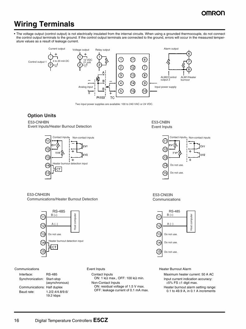
Wiring Terminals• The voltage output (control output) is not electrically insulated from the internal circuits. When using a grounded thermocouple, do not connect
the control output terminals to the ground. If the control output terminals are connected to the ground, errors will occur in the measured temper-ature values as a result of leakage current.
12 VDC 21 mAControl output 1
Analog input Input power supply
Alarm output
Two input power supplies are available: 100 to 240 VAC or 24 VDC.
Voltage output Relay outputCurrent output
ALM2/Control output 2
ALM1/Heater burnout
4 to 20 mA DC
Contact inputs Non-contact inputs
Heater burnout detection input
E53-CNBN Event Inputs
Contact inputs Non-contact inputs
Do not use.
Do not use.
E53-CNHBN Event Inputs/Heater Burnout Detection
Do not use.
E53-CN03N Communications
Do not use.
Do not use.
Do not use.
E53-CNH03N Communications/Heater Burnout Detection
Hos
t com
pute
r
Hos
t com
pute
r
Option Units
Heater burnout detection input
B (+)
A (−)
RS-485B (+)
A (−)
RS-485
Communications
Interface: RS-485Synchronization: Start-stop
(asynchronous)Communications: Half duplexBaud rate: 1.2/2.4/4.8/9.6/
19.2 kbps
Event Inputs
Contact Inputs ON: 1 kΩ max., OFF: 100 kΩ min.Non-Contact Inputs ON: residual voltage of 1.5 V max. OFF: leakage current of 0.1 mA max.
Heater Burnout Alarm
Maximum heater current: 50 A ACInput current indication accuracy: ±5% FS ±1 digit max.Heater burnout alarm setting range: 0.1 to 49.9 A, in 0.1 A increments

Digital Temperature Controllers E5AZ/E5EZ/E5CZ 17
Nomenclature
E5AZ
E5EZ
PV
SV
ALM1
ALM2
ALM3
HB
OUT1
OUT2
STOP
CMW
E5AZ
Temperature UnitOperation Indicators No. 1 Display
No. 2 Display
Up Key
Down Key
Level Key
Mode Key
Level + Mode Keys
1. ALM1 (alarm 1) Lights when the alarm 1 output is ON. ALM2 (alarm 2) Lights when the alarm 2 output is ON. ALM3 (alarm 3) Lights when the alarm 3 output is ON.
2. HB (heater burnout alarm display) Lights when a heater burnout is detected. The heater burnout alarm can be held ON by setting the heater burnout latch. To reset, turn the power supply OFF and then ON or set the heater burnout alarm value to 0.0 A.
3. OUT1, OUT2 (control output 1, control output 2) Lights when control output 1 or control output 2 (cool) is ON. However, if control output 1 is a current output, OUT1 will always be not lit.
4. STOP (stop) Lights when control of the E5AZ has been stopped. During control, this indicator lights when an event or the run/stop function has become stopped. Otherwise, this indicator is not lit.
5. CMW (communications writing control) Lights when communications writing is enabled and is not lit when it is disabled.
The temperature unit is displayed when the dis-play unit parameter is set to a temperature. In-dication is determined by the currently selected "temperature unit" parameter set value. When this parameter is set to "°C," "c" is displayed, and when set to "°F," "f" is displayed.
Displays the process value or param-eter type.
Displays the set point, manipulated variable, or set value (setup) of the parameter.
Each press of this key increases val-ues displayed on the No.2 display. Holding down this key continuously increases values.
Each press of this key decreases val-ues displayed on the No.2 display. Holding down this key continuously de-creases values.
This key combination sets the E5AZ to the "protect level."
Press this key to select parameters within each level.
Press this key to select the setup level. The setup level is selected in order "operation level" ←→ "adjustment level," "initial setting level" ←→ "communications setting level."
PV
SV
ALM1 ALM2 ALM3 HB
OUT1 OUT2 STOP CMW
E5EZ
Temperature UnitOperation Indicators No. 1 Display
No. 2 Display
Up Key
Down Key
Level Key
Level + Mode KeysMode Key
1. ALM1 (alarm 1) Lights when the alarm 1 output is ON. ALM2 (alarm 2) Lights when the alarm 2 output is ON. ALM3 (alarm 3) Lights when the alarm 3 output is ON.
2. HB (heater burnout alarm display) Lights when a heater burnout is detected. The heater burnout alarm can be held ON by setting the heater burnout latch. To reset, turn the power supply OFF and then ON or set the heater burnout alarm value to 0.0 A.
3. OUT1, OUT2 (control output 1, control output 2) Lights when control output 1 or control output 2 (cool) is ON. However, if control output 1 is a current output, OUT1 will always be not lit.
4. STOP (stop) Lights when control of the E5EZ has been stopped.During control, this indicator lights when an event or the run/stop function has become stopped. Otherwise, this indicator is not lit.
5. CMW (communications writing control) Lights when communications writing is enabled and is not lit when it is disabled.
The temperature unit is displayed when the dis-play unit parameter is set to a temperature. In-dication is determined by the currently selected "temperature unit" parameter set value. When this parameter is set to "°C," "c" is displayed, and when set to "°F," "f" is displayed.
Displays the process value or param-eter type.
Displays the set point, manipulated variable, or set value (setup) of the pa-rameter.
Each press of this key increases val-ues displayed on the No.2 display. Holding down this key continuously increases values.
Each press of this key decreases val-ues displayed on the No.2 display. Holding down this key continuously decreases values.
This key combination sets the E5EZ to the "protect level."
Press this key to select the setup lev-el. The setup level is selected in order "operation level" ←→ "adjustment level," "initial setting level" ←→ "communications setting level."
Press this key to select parameters within each level.

18 Digital Temperature Controllers E5AZ/E5EZ/E5CZ
E5CZ
PV
SV
ALM1
ALM2
OUT1
HB
OUT2
STOP
CMW
E5CZ
Temperature UnitOperation Indicators No. 1 Display
Displays the process value or parameter type.
No. 2 Display
Up Key
Down Key
Mode Key
Level KeyLevel + Mode Keys
1. ALM1 (alarm 1) Lights when the alarm 1 output is
ON. ALM2 (alarm 2) Lights when the alarm 2 output is
ON.2. HB (heater burnout alarm display) Lights when a heater burnout is de-
tected. The heater burnout alarm can be
held ON by setting the heater burn-out latch. To reset, turn the power supply OFF and then ON or set the heater burnout alarm value to 0.0 A.
3. OUT1, OUT2 (control output 1, con-trol output 2)
Lights when control output 1 or con-trol output 2 (cool) is ON.
However, if control output 1 is a cur-rent output, OUT1 will always be not lit.
4. STP (stop) Lights when control of the E5CZ has
been stopped. During control, this indicator lights
when an event or the run/stop func-tion has become stopped. Otherwise, this indicator is not lit.
5. CMW (communications writing con-trol)
Lights when communications writing is enabled and is not lit when it is dis-abled.
The temperature unit is displayed when the dis-play unit parameter is set to a temperature. Indi-cation is determined by the currently selected "temperature unit" parameter set value. When this parameter is set to "°C," "c" is displayed, and when set to "°F," "f" is displayed.
Displays the set point, manipulated variable, or set value (setup) of the parameter.
Each press of this key increases values displayed on the No.2 display. Holding down this key continuously increases values.
Each press of this key decreases values displayed on the No.2 display. Holding down this key continuously decreases values.
This key combination sets the E5CZ to the "protect level."
Press this key to select parameters within each level.
Press this key to select the setup level. The setup level is selected in order "operation level" ←→ "adjustment level," "initial setting level" ←→ "communications setting level."
Digital Temperature Controllers E5AZ/E5EZ/E5CZ 19
Operation
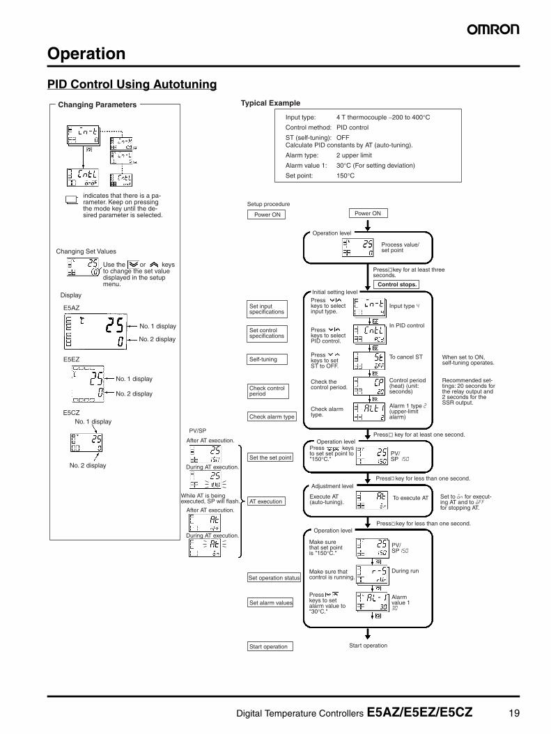
PID Control Using Autotuning
Changing Set Values
Display
E5CZNo. 1 display
No. 2 display
Setup procedure
Power ON
Self-tuning
Set alarm values
Start operation
Power ON
Operation level
In PID control
To cancel ST
Press key for at least one second.
Press key for less than one second.Adjustment level
Operation level
To execute AT
Press key for less than one second.
During run
Start operation
Operation level
Check alarm type
Set the set point
Set operation status
Typical Example
AT execution
Input type 4
Initial setting level
After AT execution.
During AT execution.
PV/SP
After AT execution.
During AT execution.
Changing Parameters
E5EZ
No. 1 display
No. 2 display
E5AZ
No. 1 display
No. 2 display
indicates that there is a pa-rameter. Keep on pressing the mode key until the de-sired parameter is selected.
Use the or keys to change the set value displayed in the setup menu.
While AT is being executed, SP will flash.
Input type: 4 T thermocouple −200 to 400°CControl method: PID control
ST (self-tuning): OFFCalculate PID constants by AT (auto-tuning).
Alarm type: 2 upper limit
Alarm value 1: 30°C (For setting deviation)
Set point: 150°C
Process value/ set point
Press key for at least three seconds.
Set input specifications
Set control specifications
Check control period
Press keys to select input type.
Press keys to select PID control.
Press keys to set ST to OFF.
Check the control period.
Check alarm type.
Control period (heat) (unit: seconds)
Alarm 1 type 2 (upper-limit alarm)
Recommended set-tings: 20 seconds for the relay output and 2 seconds for the SSR output.
Press keys to set set point to "150°C."
PV/ SP 150
Execute AT (auto-tuning).
Set to on for execut-ing AT and to off for stopping AT.
Make sure that set point is "150°C."
PV/ SP150
Make sure that control is running.
Press keys to set alarm value to "30°C."
Alarm value 1 30
Control stops.
When set to ON, self-tuning operates.

20 Digital Temperature Controllers E5AZ/E5EZ/E5CZ
Specification Setting after Turning ON Power
Outline of Operation Procedures
Key OperationIn the following descriptions, all the parameters are introduced in the display sequence. Some parameters may not be displayed depending on theprotect settings and operation conditions.
Description of Each Level
Operation LevelThis level is displayed when you turn the power ON. You can move tothe protect level, initial setting level and adjustment level from thislevel.
Normally, select this level during operation. During operation, theprocess value, set point and manipulated variable can be monitored,and the alarm value and upper- and lower-limit alarms can be moni-tored and modified.
Adjustment LevelTo select this level, press the key once for less than one second.
This level is for entering set values and offset values for control. Thislevel contains parameters for setting the set values, AT (auto-tuning),communications writing enable/disable, hysteresis, multi-SP, inputshift values, heater burnout alarm (HBA) and PID constants. You canmove to the top parameter of the operation level or initial setting levelfrom here.
Initial Setting LevelTo select this level, press the key for at least three seconds in theoperation level. This level is for specifying the input type, selectingthe control method, control period, setting direct/reverse action andalarm type. You can move to the advanced function setting level orcommunications setting level from this initial setting level. To return to
the operation level, press the key for at least one second. Tomove to the communications setting level, press the key once forless than one second.
Protect LevelTo select this level, simultaneously press the and M keys for atleast 3 seconds. This level is to prevent unwanted or accidental mod-ification of parameters. Protected levels will not be displayed, and sothe parameters in that level cannot be modified.
Communications Setting LevelTo select this level, press the key once for less than one second inthe initial setting level. When the communications function is used,set the communications conditions in this level. Communicating witha personal computer (host computer) allows set points to be readand written, and manipulated variables to be monitored.
Advanced Function Setting LevelTo select this level, you must enter the password (“-169”) in the initialsetting level.
You can move only to the calibration level from this level.
This level is for setting the automatic return of display mode, MV lim-iter, event input assignment, standby sequence, alarm hysteresis, ST(self-tune) and to move to the user calibration level.
Power ON
Operation level Adjustment level
+ key 1 second min.
Control stops.
Protect levelInitial setting level
Control in progress
Control stopped
Level change
key 1 second min.
+ key 3 seconds min.
+ key Display flashes when key pressed.
key
key Less than 1 second
key 1 second min.
key 3 seconds min.
Display flashes when key held down for more than 1 second.
Communica-tions setting level key
Less than 1 second
Password input set value "−169"
Advanced function setting level
The time taken to move to the protect level can be adjusted by changing the "Move to protect level time" setting.
Note: Of these levels, the initial setting level, communications set-ting level, advanced function setting level and calibration level can be used only when control has stopped. Note that control is stopped when these four levels are selected. When switched back to the operation level from one of these levels, control will start.

Digital Temperature Controllers E5AZ/E5EZ/E5CZ 21
Specification Setting after Turning ON Power
Initial Setting LevelThis level is used for setting basic specifications of the TemperatureController. Using this level, set the input type for selecting the input tobe connected such as the thermocouple or platinum resistance ther-mometer and set the range of set point and the alarm mode.
The move from the operation level to the initial setting level, press key for three seconds or more.
The initial setting level is not displayed when “initial/communicationsprotection” is set to “2.” This initial setting level can be used when“initial setting/communications protection” is set to “0” or “1.”
The “scaling upper limit,” “scaling lower limit,” and “decimal point”parameters are displayed when an analog voltage input is selectedas the input type.
To return to the operation level, press the key for longer than onesecond.
* Not displayed as default setting.
Power ON
Operation level Adjustment level
Less than 1 second
1 second min.
Less than 1 second
Control stops.
1 second min.
Protect level
key+
1 second min.key
key
key
key
keykey+
key+
Control in progress
Control stopped
Level change
3 seconds min.
Initial setting level
Communica-tions setting level
Password input set value "−169"
Advanced function setting level
Display flashes when key pressed.
3 seconds min.
The time taken to move to the protect level can be adjusted by changing the "Move to protect lev-el time" setting.
Initial setting level
Input type
Scaling upper limit
Scaling lower limit
Decimal point
SP upper limit
SP lower limit
PID ON/OFF
ST
Control period (heating)
Control period (cooling)
Direct/reverse operation
Alarm 1 type
Alarm 2 type
(PID control)
Set the pulse output cycle.
(Displayed when initial setting/communications protection is set to 0.)
For analog input
Temperature unit
Standard or heating/ cooling
Alarm output type
(PID control) (Heating/cooling setting)
Alarm 3 type
Select the alarm mode. (Models with alarm function)
Move to advanced function setting level
22 Digital Temperature Controllers E5AZ/E5EZ/E5CZ
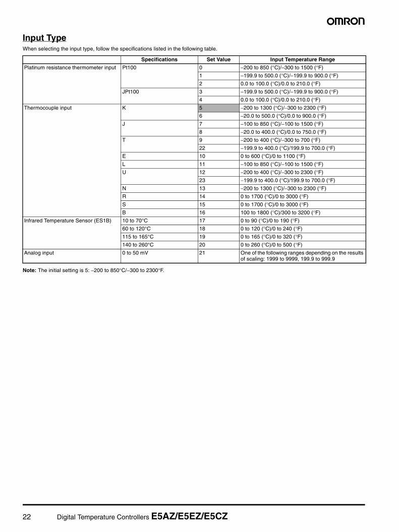
Input TypeWhen selecting the input type, follow the specifications listed in the following table.
Note: The initial setting is 5: −200 to 850°C/−300 to 2300°F.
Specifications Set Value Input Temperature Range
Platinum resistance thermometer input Pt100 0 −200 to 850 (°C)/−300 to 1500 (°F)
1 −199.9 to 500.0 (°C)/−199.9 to 900.0 (°F)
2 0.0 to 100.0 (°C)/0.0 to 210.0 (°F)
JPt100 3 −199.9 to 500.0 (°C)/−199.9 to 900.0 (°F)
4 0.0 to 100.0 (°C)/0.0 to 210.0 (°F)
Thermocouple input K 5 −200 to 1300 (°C)/−300 to 2300 (°F)
6 −20.0 to 500.0 (°C)/0.0 to 900.0 (°F)
J 7 −100 to 850 (°C)/−100 to 1500 (°F)
8 −20.0 to 400.0 (°C)/0.0 to 750.0 (°F)
T 9 −200 to 400 (°C)/−300 to 700 (°F)
22 −199.9 to 400.0 (°C)/199.9 to 700.0 (°F)
E 10 0 to 600 (°C)/0 to 1100 (°F)
L 11 −100 to 850 (°C)/−100 to 1500 (°F)
U 12 −200 to 400 (°C)/−300 to 2300 (°F)
23 −199.9 to 400.0 (°C)/199.9 to 700.0 (°F)
N 13 −200 to 1300 (°C)/−300 to 2300 (°F)
R 14 0 to 1700 (°C)/0 to 3000 (°F)
S 15 0 to 1700 (°C)/0 to 3000 (°F)
B 16 100 to 1800 (°C)/300 to 3200 (°F)
Infrared Temperature Sensor (ES1B) 10 to 70°C 17 0 to 90 (°C)/0 to 190 (°F)
60 to 120°C 18 0 to 120 (°C)/0 to 240 (°F)
115 to 165°C 19 0 to 165 (°C)/0 to 320 (°F)
140 to 260°C 20 0 to 260 (°C)/0 to 500 (°F)
Analog input 0 to 50 mV 21 One of the following ranges depending on the results of scaling: 1999 to 9999, 199.9 to 999.9

Digital Temperature Controllers E5AZ/E5EZ/E5CZ 23
Alarm TypesSelect the alarm type from the 12 types listed in the following table.
Note 1: With set values 1, 4 and 5, the upper and lower limit valuescan be set independently for each alarm type, and are ex-pressed as “L” and “H.” Following operations are for cases when an alarm set pointis “X” or negative.
2: Set value: 1, Upper- and lower-limit alarm
3: Set value: 4, Upper- and lower-limit range
4: Set value: 5, Upper- and lower-limit with standby sequence
5: Set value: 5, Upper- and lower-limit with standby sequencealarm. Always OFF when the upper-limit and lower-limit hys-teresis overlaps.Set the alarm types for alarm 1 and alarm 2 independently inthe initial setting level. The default setting is 2 (upper limit).With the E5AZ/E5EZ, perform settings similarly for alarm 3.
Set Value Alarm Type Alarm Output Operation
When X is positive When X is negative
0 Alarm function OFF Output OFF
1 (See note 1.) Upper- and lower-limit (deviation) (See note 2.)
2 Upper-limit (deviation)
3 Lower-limit (deviation)
4 (See note 1.) Upper- and lower-limit range (deviation) (See note 3.)
5 (See note 1.) Upper- and lower-limit with standby se-quence (deviation)
(See note 4.)
6 Upper-limit with standby sequence (de-viation)
7 Lower-limit with standby sequence (de-viation)
8 Absolute-value upper-limit
9 Absolute-value lower-limit
10 Absolute-value upper-limit with standby sequence
11 Absolute-value lower-limit with standby sequence
(See note 5.)
=
=
Case 1 Case 2 Case 3 (Always ON)
=
=
L H
Case 1 Case 2 Case 3 (Always OFF)
Case 1 Case 2Example
Same as for the upper- and lower-limit alarm. However, when the upper-limit and lower-limit hysteresis overlaps: Always OFF
0°C/°F
Example: When the alarm is set ON at 110°C/°F or higher.
Alarm value Alarm value
(For alarm types 1 to 7) The alarm value is set as a deviation from the set point.
When an alarm type other than the absolute-value alarm is selected (For alarm types 8 to 11)
The alarm value is set as an absolute value from the alarm value of 0°C/F.
When the absolute-value alarm is selected
Set point 100°C/°F

24 Digital Temperature Controllers E5AZ/E5EZ/E5CZ
ParametersParameters related to setting items for each level are marked inboxes in the flowcharts and brief descriptions are given as required.At the end of each setting item, press the mode key to return to thebeginning of each level.
Control stops.
Initial setting level
Less than 1 s
Power ON
Operation level
Protect level
Control in progress
Control stopped
Adjustment level
Level change
Less than 1 s
key
key
key
key
key
+ key
+ key
+ key
+ key
1 s min. 3 s min.
1 s min.
Display flashes when key held down for more than 1 s.
Communica-tions setting level
Password input set value "−169"
Advanced function setting level
Display flashes when key pressed.
3 s min.
The time taken to move to the protect level can be adjusted by changing the "Move to protect level time" setting.
1 s min.
Display
E5CZNo. 1 display
No. 2 display
E5EZ
No. 1 display
No. 2 display
E5AZ
No. 1 display
No. 2 display
key 1 s min.
Advanced Function Setting Level
Note: To select advanced function setting level, you must enter the password ("−169") in the initial setting level.
Parameter initialization
Alarm 2 hysteresis
Alarm 2 open in alarm
Alarm 1 hysteresis
Alarm 1 open in alarm
Multi-SP uses
Event input assignment 2
Event input assignment 1
Number of multi-SP usesSelect 2 or 4.
Heater burnout detection
MV upper limit
ST stable range
Heater burnout hysteresis
Heater burnout latchLatch after heater burnout detection
SP ramp set valueRate of change during ramp
Resets to the default value.
Limitations to MV
For setting deviation.
Alarm 3 hysteresis
Alarm 3 open in alarm
Standby sequence reset method
MV lower limit
Input setting: Multi-SP/RUN/STOP
Restarting condition after clearing standby
ON/OFF setting of alarm output 1
ON/OFF setting of alarm output 2
ON/OFF setting of alarm output 3
α2-PID parameter
Alarm 1 ON delay
Alarm 2 ON delay
Alarm 3 ON delay
Move to protect level time
Input error output
Cold junction compensating method
MB command logic switching
Input digital filter
Additional PV displayDisplayed first in the operation level
MV display
Automatic return of display mode
Alarm ON/OFF delays
Alarm 1 OFF delay
Alarm 2 OFF delay
Alarm 3 OFF delay

Digital Temperature Controllers E5AZ/E5EZ/E5CZ 25
Note: These diagrams show all the parameters that may be displayed. Depending on the specifications of the model used, there may be someparameters that are not displayed.
Input ShiftAll points in the sensor range are shifted by the value set as the tem-perature input shift value.
Example
Power ON
Operation LevelInitial Setting Level Adjustment Levelkey 3 s min.
key 1 s min.
key Less than 1 s
key Less than 1 s
c: °C
f: °F
Input type
Scaling upper limit
Decimal point
Temperature unit
SP upper limit
PID ON/OFF
Standard or heating/cooling
Control period (heating)
Alarm 1 type
Direct/reverse operationControls the MV in responseincreases or decreases in the PV.
Alarm 2 type
Limit the set point.
Select the control system.
ST
Control period (cooling)OUT2
Number of displayed digits
SP lower limit
Scaling lower limit
Alarm 3 type
OUT1
For analog input
Set the pulse output cycle.
Select the alarm mode.
Move to advanced function setting level
Note: This parameter is not displayed as a default set-ting. To move to the advanced function setting level, change the initial setting/communications protection setting from 1 to 0. (See page 26.)
Process value
Process value/set point
Multi-SP set point setting
SP ramp monitor
Heater current value monitor
Run/stop
Alarm value 1
Alarm value 2
MV monitor (cooling)
MV monitor (heating)
Alarm value 3
Add in the "additional PV display" parameter.
Upper-limit alarm value 1
Set either of these parameters.
Lower-limit alarm value 1
Set either of these parameters.
Upper-limit alarm value 2
Lower-limit alarm value 2
Set either of these parameters.
Upper-limit alarm value 3
Lower-limit alarm value 3
The displays for parameters which can be switched (i.e., parameters other than simply numerical ones) show the contents of those parameters.
P
I
D
Hysteresis (heating)
AT execute/cancel
Communications writing
SP 0
SP 1
Temperature input shift 1-point shift
2-point shift (see note)
Proportional band
PID settings
Cooling coefficient
Dead band
Manual reset value
SP 2
SP 3
Derivative time
Integral time
Set hysteresis.Hysteresis (cooling)
Heater current value monitor
Heater burnout detection
HBA function
SP used by multi-SP
Upper-limit temperature input
Lower-limit temperature input
Used in heating and cooling control
Clear the offset during stabilization of P or PD control.
The 2-point shift setting is only possible when the input type is an infrared temperature sensor.
Input shift setting Temperature measured by
sensor
Temperature display
0 (no shift) 100°C 100°C10 (shifted +10°C) 100°C 110°C−10 (shifted −10°C) 100°C 90°C

26 Digital Temperature Controllers E5AZ/E5EZ/E5CZ
Protect Level
Operation/Adjustment ProtectionThe following table shows the relationship between set values andthe range of protection.
When this parameter is set to “0,” parameters are not protected.
Initial Setting/Communications ProtectionThis protect level restricts movement to the initial setting level, com-munications setting level and advanced function setting level.
Default setting: 1: Move to other levels possibleX: Move to other levels not possible
Setting Change ProtectionThis protect level protects setup from being changed by operatingthe keys on the front panel.
Default setting: OFF
Level Set value
0 1 2 3
Operation level PV
PV/SP
Other X X
Adjustment level X X X
Set value
Initial setting level Communications setting level
Advanced function setting
level
0
1 X
2 X X X
Set value Description
OFF Setup can be changed by key operation.
ON Setup cannot be changed by key operation. (The protect level, can be changed.)
Operation/adjustment protection
Initial setting/communications protection
Setting change protection
Restricts displaying and modifying menus in operation, adjustment, and manual control levels.
This protect level restricts movement to the initial setting, communications setting, and advanced function setting levels.
Protects changes to setups by operating the front panel keys.
Default setting: 0
: Can be displayed and changed: Can be displayedX : Cannot be displayed and move to other levels not possible

Digital Temperature Controllers E5AZ/E5EZ/E5CZ 27
Communications Setting LevelSet the E5AZ/E5EZ/E5CZ communications specifications in the communications setting level. For setting communications parameters, use theE5AZ/E5EZ/E5CZ panel. The communications parameters and their settings are listed in the following table.
Note: The highlighted values indicate default settings.
Before executing communications with the E5AZ/E5EZ/E5CZ, setthe communications unit No., baud rate, etc., through key operationsas described below. As for other operations, refer to relevant Opera-tion Manual.
1. Press the key for at least three seconds in the “operationlevel.” The level moves to the “initial setting level.”
2. Press the key for less than one second. The “initial settinglevel” moves to the “communications setting level.”
3. Pressing the key advances the parameters as shown in thefollowing figure.
4. Press the or keys to change the parameter setups.
Note: On the E5AZ/E5EZ, the key is the key.
Set each communications parameter to match those of the communi-cating personal computer.
Communications Unit No. (u-no)When communicating with the host computer, the unit number mustbe set in each Temperature Controller so that the host computer canidentify each Temperature Controller. The number can be set in arange from 0 to 99 in increments of 1. The default setting is 1. Whenusing more than one Unit, be careful not to use the same numbertwice. Duplicate settings will cause malfunction. This value becomesvalid when the power is turned OFF and ON again.
Baud Rate (bps)Use this parameter to set the speed of communications with the hostcomputer. It can be set to one of the following values; 1.2 (1200 bps),2.4 (2400 bps), 4.8 (4800 bps), 9.6 (9600 bps), and 19.2(19200 bps).This setting becomes valid when the power is turned OFF and ONagain.
Data Bits (len)Use this parameter to change the communications data bit length to7 bits or 8 bits.
Stop Bits (sbit)Use this parameter to change the communications stop bit to 1 or 2.
Communications parity (prty)Use this parameter to set the communications parity to None, Even,or Odd.
TroubleshootingWhen an error occurs, an error code will be displayed on the No. 1 display. Check the contents of an error and take appropriate countermeasures.
Note 1. If the input is within the range for which control is possible but outside the displayable range (−1999 (−199.9) to 9999 (999.9)), will bedisplayed if the value is less than −1999 (−199.9), and will be displayed if it is greater than 9999 (999.9). Control output and alarmoutput will operate normally for either of these displays. Refer to the relevant User’s Manual for details on the ranges for which control ispossible.
2. These errors are displayed only when the Controller is set to display the present value or the present value and the set value. They are notdisplayed in other statuses.
Parameter Displayed characters Set (monitor) value Set value
Communications unit No. u-no 0 to 99
Baud rate bps 1.2/2.4/4.8/9.6/19.2 (kbps)
Data bits len 7/8 (bit)
Stop bits sbit 1/2
Parity prty None, even, odd
0.1 to 99
1.2/2.4/4.8/9.6/19.2
7/8 (bit)
1/2 (bit)
none/euen/odd
Baud rate
Data bits
Stop bits
Communications parity
Communications unit No.
No.1 display Contents Countermeasure Output status
Control output Alarm output
s.err (S. Err) Input error (See note.) Check that the input wiring is correct, that there is no discon-nection or short-circuit, and that the input type is correct. (Thermocouple input short-circuits cannot be detected.)
OFF Handled as ab-normally high temperature
A/D converter error(See note.)
After noting the error, reset the power. If the display does not change, replacement is necessary. If the error is removed, it is possible that the original error was caused by noise. Check that there are no possible sources of noise.
OFF OFF
e111 (E111) Memory error Reset the power. If the display does not change, replacement is necessary. If the error is removed, it is possible that the original error was caused by noise. Check that there are no possible sources of noise.
OFF OFF
h.err (H. Err) HB error (See note.) OFF OFF
((((
))))

28 Digital Temperature Controllers E5AZ/E5EZ/E5CZ
Peripheral Devices
Temperature Sensor / SSRConnection Example with SSR
PV
SV
ALM1
ALM2
ALM3
HB
OUT1
OUT2
STOP
CMW
E5AZ
PV
SV
ALM1 ALM2 ALM3 HB
OUT1 OUT2 STOP CMW
E5EZ
PV
SV
ALM1
ALM2
OUT1
OUT2
STOP
E5CZ
Temperature ControllerLoad
Heater
Load power
Direct connection possible
E5EZE52
ES1B
E5CZ
E5AZ
For controlling high-power heater
G3NH: 440 VAC (75 A, 150 A)
Standard models with screw terminals
G3NE: 240 VAC (5 A, 10 A, 20 A)
3 units 5 units (E5AZ/ E5EZ)
G3PB (Single-phase): 240 VAC (15 A, 25 A, 35 A, 45 A)
Rated input voltage: 12 to 24 VDC
2 units 4 units (E5AZ/ E5EZ)
3 units 5 units (E5AZ/ E5EZ)
Compact and slim models with a built-in radiator
G3PB (Three-phase): 240 VAC/400 VAC (15 A, 25 A, 35 A, 45 A)
Rated input voltage: 12 to 24 VDC
Simultaneous three-phase control with a built-in radiator
G3PA: 240 VAC (10 A, 20 A, 40 A) 400 VAC (20 A, 30 A)
Rated input voltage: 5 to 24 VDC
Compact and slim models with a built-in radiator
3 units 5 units (E5AZ/ E5EZ)
4 units for 480-VAC models
1 unit 2 units (E5AZ/ E5EZ)
G3NA: 240 VAC (5 A, 10 A, 20 A, 40 A) 480 VAC (10 A, 20 A, 40 A)
Rated input voltage: 5 to 24 VDC
Rated input voltage: 12 VDC
Compact and low-cost models with tab terminals
4 units 8 units (E5AZ/ E5EZ)
Rated input voltage: 5 to 24 VDC
Voltage output terminal (for driving SSR)
Number of Connectable SSRs
Note: 480 VAC models: 4 units
A: G3PB (Single-phase) G3PA
B: G3PB (Three-phase)
C: G3NA(See note.)
D: G3NE E: G3NH
E5AZ/EZ 5 units 4 units 5 units 2 units 4 units
E5CZ 3 units 2 units 3 units 1 unit 8 units


