![ETE 204 - Digital Electronics Flip-Flops and Registers [Lecture:13] Instructor: Sajib Roy Lecturer, ETE, ULAB.](https://static.fdocuments.net/doc/165x107/56649db65503460f94aa80af/ete-204-digital-electronics-flip-flops-and-registers-lecture13-instructor.jpg)
Digital Electronics Electronics Technology Landon Johnson Shift Registers.
23
Digital Digital Electronics Electronics Electronics Technology Electronics Technology Landon Johnson Shift Registers
-
Upload
ernest-fisher -
Category
Documents
-
view
247 -
download
6
Transcript of Digital Electronics Electronics Technology Landon Johnson Shift Registers.
Digital ElectronicsDigital Electronics
Electronics TechnologyElectronics Technology
Landon Johnson
Shift Registers
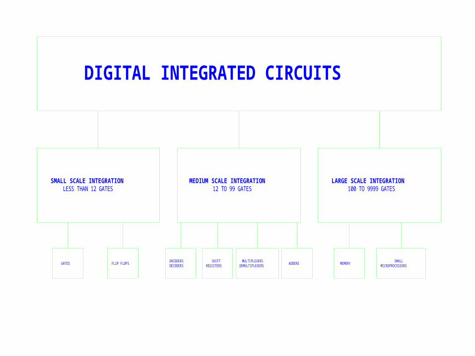
DIGITAL INTEGRATED CIRCUITS
SMALL SCALE INTEGRATIONLESS THAN 12 GATES
MEDIUM SCALE INTEGRATION12 TO 99 GATES
LARGE SCALE INTEGRATION100 TO 9999 GATES
GATES FLIP FLOPSENCODERSDECODERS
SHIFTREGISTERS
MULTIPLEXERSDEMULTIPLEXERS
ADDERS MEMORYSMALL
MICROPROCESSORS
Shift Register Competencies39. Without references, the student will define the 39. Without references, the student will define the term “Serial Data Transmission” with 100% accuracy.term “Serial Data Transmission” with 100% accuracy.
40. Without references, the student will define the 40. Without references, the student will define the term “Parallel Data Transmission” with 100% term “Parallel Data Transmission” with 100% accuracy.accuracy.
41. Without references, the student will define the 41. Without references, the student will define the acronym “SISO” with 100% accuracy.acronym “SISO” with 100% accuracy.
42. Without references, the student will define the 42. Without references, the student will define the acronym “SIPO” with 100% accuracy.acronym “SIPO” with 100% accuracy.
Shift Register Competencies43. Without references, the student will define the 43. Without references, the student will define the acronym “PISO” with 100% accuracy.acronym “PISO” with 100% accuracy.
45. Given a specified register, the student will 45. Given a specified register, the student will draw the register with 100% accuracydraw the register with 100% accuracy
44. Without references, the student will define the 44. Without references, the student will define the acronym “PIPO” with 100% accuracy.acronym “PIPO” with 100% accuracy.
46. Given a specified SISO or SIPO register, the student 46. Given a specified SISO or SIPO register, the student will state the number of pulses to completely load the will state the number of pulses to completely load the register with 100% accuracy.register with 100% accuracy.
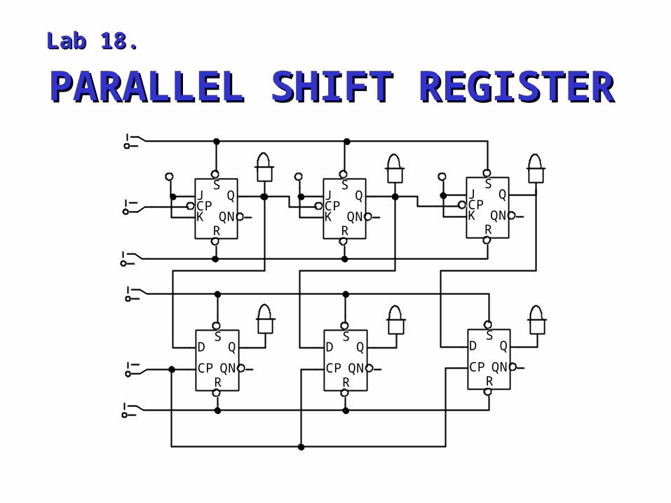
PARALLEL SHIFT REGISTERPARALLEL SHIFT REGISTERLab 18.Lab 18.
SD
CPRQN
QS
D
CPRQN
QS
D
CPRQN
Q
SJCPK
RQN
QS
JCPK
RQN
QS
JCPK
RQN
Q
SD
CPRQN
QS
D
CPRQN
QS
D
CPRQN
Q
SJCPK
RQN
QS
JCPK
RQN
QS
JCPK
RQN
Q
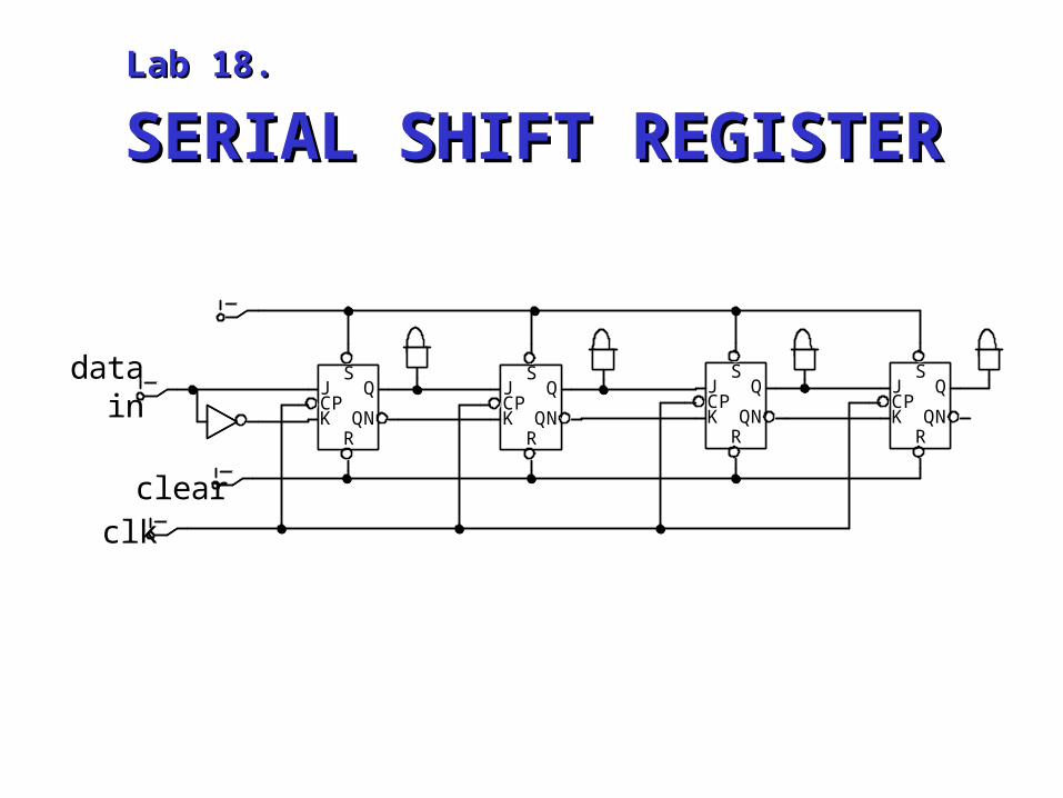
SERIAL SHIFT REGISTERSERIAL SHIFT REGISTERLab 18.Lab 18.
data in
clearclk
SJCPK
RQN
QS
JCPK
RQN
QS
JCPK
RQN
QS
JCPK
RQN
QS
JCPK
RQN
QS
JCPK
RQN
QS
JCPK
RQN
QS
JCPK
RQN
Q
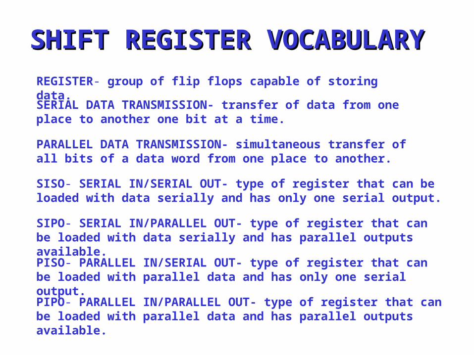
SHIFT REGISTER VOCABULARYSHIFT REGISTER VOCABULARYREGISTER- group of flip flops capable of storing data.SERIAL DATA TRANSMISSION- transfer of data from one place to another one bit at a time.
PARALLEL DATA TRANSMISSION- simultaneous transfer of all bits of a data word from one place to another.
SISO- SERIAL IN/SERIAL OUT- type of register that can be loaded with data serially and has only one serial output.
SIPO- SERIAL IN/PARALLEL OUT- type of register that can be loaded with data serially and has parallel outputs available.PISO- PARALLEL IN/SERIAL OUT- type of register that can be loaded with parallel data and has only one serial output.PIPO- PARALLEL IN/PARALLEL OUT- type of register that can be loaded with parallel data and has parallel outputs available.
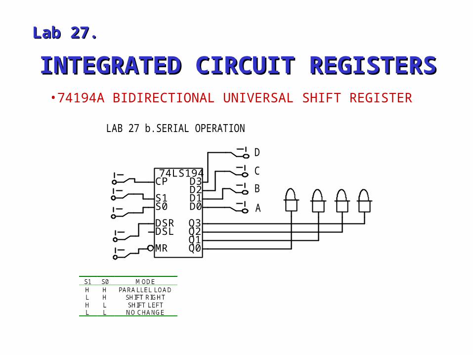
INTEGRATED CIRCUIT REGISTERSINTEGRATED CIRCUIT REGISTERS
Lab 27.Lab 27.
•74194A BIDIRECTIONAL UNIVERSAL SHIFT REGISTER
LAB 27 b.SERIAL OPERATION
DCBA
74LS194CP
S1S0
DSRDSL
MR
D3D2D1D0
Q3Q2Q1Q0
74LS194CP
S1S0
DSRDSL
MR
D3D2D1D0
Q3Q2Q1Q0
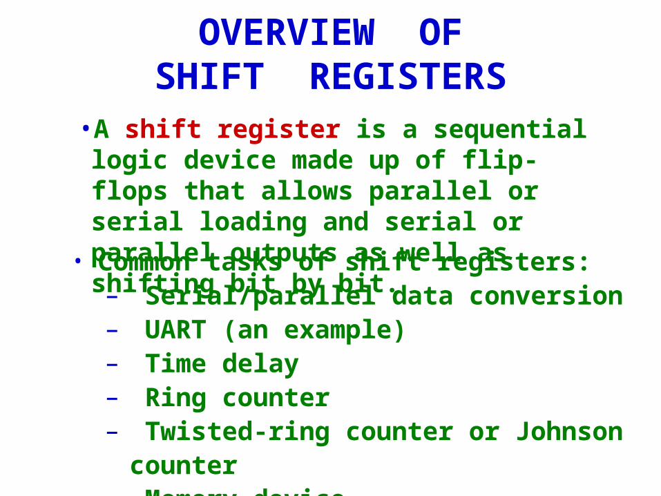
OVERVIEW OFSHIFT REGISTERS
• Common tasks of shift registers:– Serial/parallel data conversion– UART (an example)– Time delay– Ring counter– Twisted-ring counter or Johnson counter– Memory device
• A shift register is a sequential logic device made up of flip-flops that allows parallel or serial loading and serial or parallel outputs as well as shifting bit by bit.
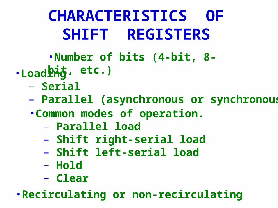
CHARACTERISTICS OF SHIFT REGISTERS
•Number of bits (4-bit, 8-bit, etc.)
•Loading– Serial– Parallel (asynchronous or synchronous)
•Common modes of operation.– Parallel load– Shift right-serial load– Shift left-serial load– Hold– Clear
•Recirculating or non-recirculating
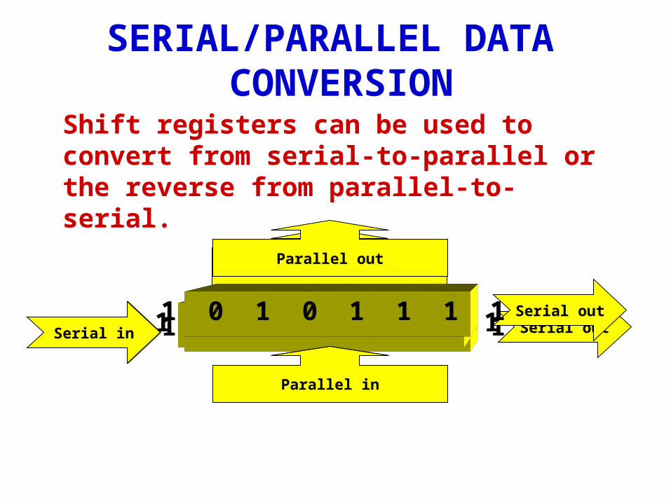
SERIAL/PARALLEL DATA CONVERSION
1 0 1 0 1 1 1 1Serial in Serial out
Shift registers can be used to convert from serial-to-parallel or the reverse from parallel-to-serial.
1 0 1 0 1 1 1 1Serial in
Parallel out
1 0 1 0 1 1 1 1 Serial out
Parallel in
1 0 1 0 1 1 1 1
Parallel in
Parallel out
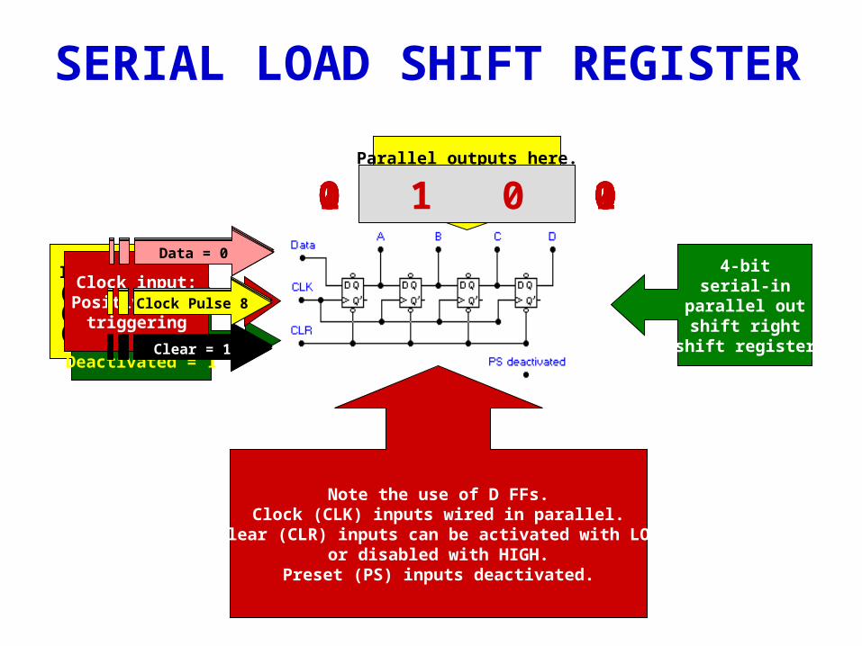
SERIAL LOAD SHIFT REGISTER
Note the use of D FFs.Clock (CLK) inputs wired in parallel.
Clear (CLR) inputs can be activated with LOWor disabled with HIGH.
Preset (PS) inputs deactivated.
Parallel outputs here.Order= A B C D
Inputs here:(1) Data(2) Clock(3) Clear
Clear input:Active = 0
Deactivated = 1
Clock input:Positive-edge
triggeringClock Pulse 1
Clear = 0
Data = 1
0 0 0 01 0 0 0
Clock Pulse 2
Clear = 1
Data = 1
1 1 0 00 1 1 0
Clock Pulse 3
Clear = 1
Data = 1
Clock Pulse 4
Clear = 1
Data = 0
0 0 1 1
Clock Pulse 5
Clear = 1
Data = 0
0 0 0 1
Clock Pulse 6
Clear = 1
Data = 0
Clock Pulse 7
Clear = 1
Data = 1
1 0 0 00 1 0 0
Clock Pulse 8
Clear = 1
Data = 04-bit
serial-inparallel outshift right
shift register
Clock Pulse 1
Clear = 0
Data = 1
Clock Pulse 2
Clear = 1
Data = 1
Clock Pulse 3
Clear = 1
Data = 0
Clock Pulse 4
Clear = 1
Data = 0
Clock Pulse 5
Clear = 1
Data = 1
QUESTION #1This is a ___ type shift register.
A. Serial-in, parallel outB. Parallel-in, serial-out
A: Serial-in, parallel-out
QUESTION #2What is the 4-bit output (bit A on left, D on right) after pulse 1?
A: 0000
QUESTION #3What is the 4-bit output (bit A on left, D on right) after pulse 2?
A: 1000
QUESTION #4What is the 4-bit output (bit A on left, D on right) after pulse 3?
A: 0100
QUESTION #5What is the 4-bit output (bit A on left, D on right) after pulse 4?
A: 0010
QUESTION #6What is the 4-bit output (bit A on left, D on right) after pulse 5?
A: 1001
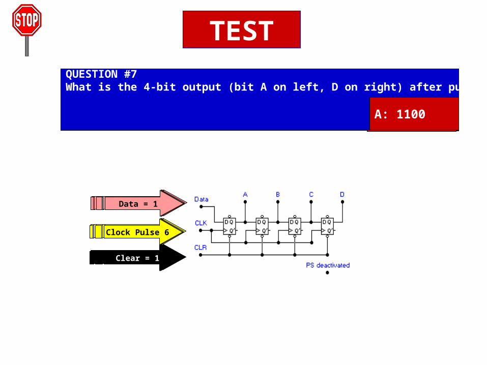
QUESTION #7What is the 4-bit output (bit A on left, D on right) after pulse 6?
A: 1100
Clock Pulse 6
Clear = 1
Data = 1
TEST
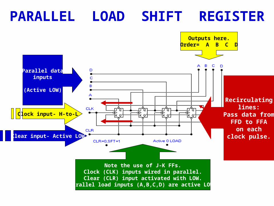
PARALLEL LOAD SHIFT REGISTER
Note the use of J-K FFs.Clock (CLK) inputs wired in parallel.
Clear (CLR) input activated with LOW.Parallel load inputs (A,B,C,D) are active LOW.
Note therecirculating
lines.
Outputs here.Order= A B C D
Parallel datainputs
(Active LOW)
Clock input- H-to-L
Clear input- Active LOW
Recirculatinglines:
Pass data fromFFD to FFA
on eachclock pulse.
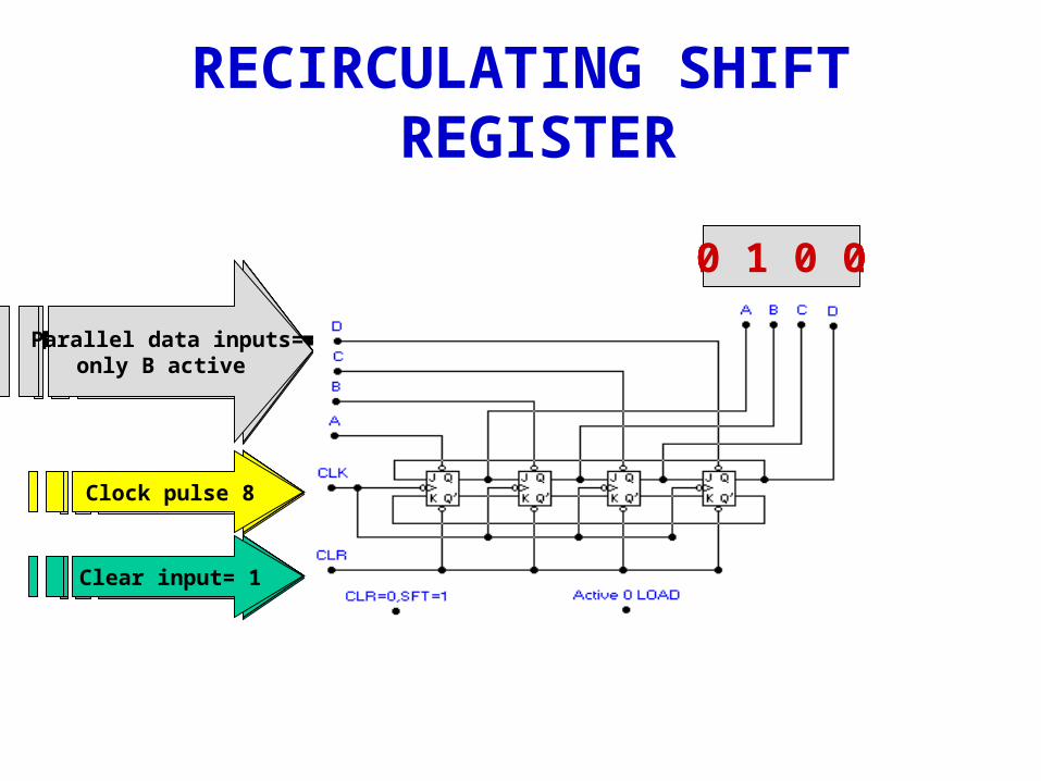
RECIRCULATING SHIFT REGISTER
0 0 0 0
Clock pulse 1
Clear input= 0
Parallel data inputs=only D activated
0 0 1 1
Clock pulse 2
Clear input= 1
Parallel data inputs=C & D activated
Clock pulse 3
Clear input= 1
Parallel data inputs=all inactive
1 0 0 1
Clock pulse 4
Clear input= 1
Parallel data inputs=all inactive
1 1 0 0
Clock pulse 5
Clear input= 1
Parallel data inputs=all inactive
0 1 1 0
Clock pulse 6
Clear input= 1
Parallel data inputs=all inactive
0 0 1 1
Clock pulse 7
Clear input= 0
Parallel data inputs=all inactive
0 0 0 0
Clock pulse 8
Clear input= 1
Parallel data inputs=only B active
0 1 0 0
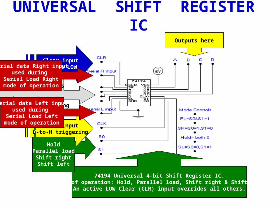
UNIVERSAL SHIFT REGISTER IC
74194 Universal 4-bit Shift Register IC.Modes of operation: Hold, Parallel load, Shift right & Shift left.
An active LOW Clear (CLR) input overrides all others.
Outputs here
Mode Controls:
HoldParallel loadShift rightShift left
Clock inputL-to-H triggering
Parallel data inputs
Order: A, B, C, Dduring Parallel loading
Clear inputactive LOWSerial data Right input
used during Serial Load Right
mode of operation
Serial data Left inputused during
Serial Load Leftmode of operation
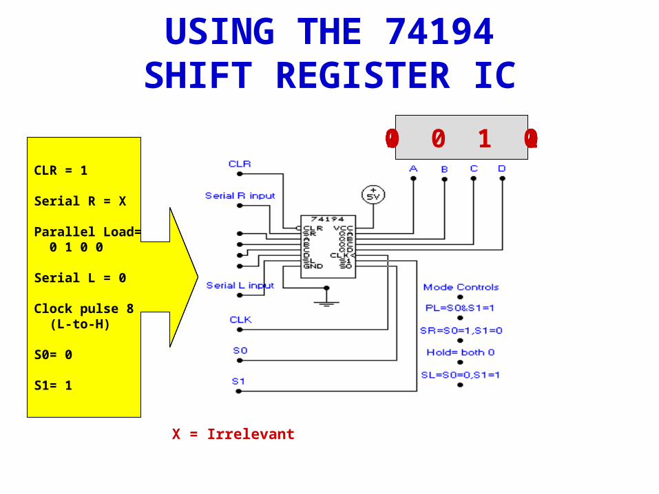
USING THE 74194 SHIFT REGISTER IC
CLR = 1
Serial R = X
Parallel Load= 0 1 1 0
Serial L = X
Clock pulse 1 (L-to-H)
S0= 1
S1= 1
0 1 1 0
X = Irrelevant
CLR = 1
Serial R = 0
Parallel Load= 0 1 1 0
Serial L = X
Clock pulse 2 (L-to-H)
S0= 1
S1= 0
0 0 1 1CLR = 1
Serial R = 0
Parallel Load= 0 1 0 0
Serial L = X
Clock pulse 3 (L-to-H)
S0= 1
S1= 0
0 0 0 1CLR = 1
Serial R = 0
Parallel Load= 0 1 0 0
Serial L = X
Clock pulse 4 (L-to-H)
S0= 0
S1= 0
0 0 0 1CLR = 0
Serial R = 0
Parallel Load= 0 1 0 0
Serial L = X
Clock pulse 5 (L-to-H)
S0= 1
S1= 1
0 0 0 0CLR = 1
Serial R = X
Parallel Load= 0 1 0 0
Serial L = X
Clock pulse 6 (L-to-H)
S0= 1
S1= 1
0 1 0 0CLR = 1
Serial R = X
Parallel Load= 0 1 0 0
Serial L = 1
Clock pulse 7 (L-to-H)
S0= 0
S1= 1
1 0 0 1CLR = 1
Serial R = X
Parallel Load= 0 1 0 0
Serial L = 0
Clock pulse 8 (L-to-H)
S0= 0
S1= 1
0 0 1 0
CLR = 0
Serial R = X
Parallel Load= 0 1 0 0
Serial L = X
Clock pulse 1 (L-to-H)
S0= 1
S1= 1
? ? ? ?
CLR = 1
Serial R = 0
Parallel Load= 0 1 0 0
Serial L = X
Clock pulse 2 (L-to-H)
S0= 1
S1= 1
CLR = 1
Serial R = 0
Parallel Load= 0 1 0 0
Serial L = X
Clock pulse 3 (L-to-H)
S0= 1
S1= 0
CLR = 1
Serial R = 0
Parallel Load= 0 1 0 0
Serial L = X
Clock pulse 4 (L-to-H)
S0= 0
S1= 0
CLR = 1
Serial R = X
Parallel Load= 0 1 0 0
Serial L = 1
Clock pulse 5 (L-to-H)
S0= 0
S1= 1
QUESTION #1The 74194 IC could be described as a 4-bit (shift right, universal)shift register.
A: Universal
QUESTION #2What is the mode of operation during and the output of the shift register after pulse 1?
A: Clear, 0 0 0 0
QUESTION #3What is the mode of operation during and the output of the shift register after pulse 2?
A: Parallel load, 0 1 0 0
QUESTION #4- What is the mode of operation during and the output of the shift register after pulse 3?
A: Shift right, 0 0 1 0
QUESTION #5What is the mode of operation during and the output of the shift register after pulse 4?
A: Hold, 0 0 1 0
QUESTION #6What is the mode of operation during and the output of the shift register after pulse 5?
A: Shift left, 0 1 0 1
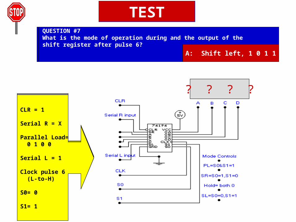
CLR = 1
Serial R = X
Parallel Load= 0 1 0 0
Serial L = 1
Clock pulse 6 (L-to-H)
S0= 0
S1= 1
QUESTION #7What is the mode of operation during and the output of the shift register after pulse 6?
A: Shift left, 1 0 1 1
TEST
SIMPLE TROUBLESHOOTING HINTS
• Feel top of IC to determine if it is hot
• Look for broken connections, signs of
excessive heat
• Smell for overheating
• Check power source
• Trace path of logic through circuit
• Know the normal operation of the circuit