Difficulties in the Interpretation of Chest Radiography
24
27 E.E. Coche et al. (eds.), Comparative Interpretation of CT and Standard Radiography of the Chest, Medical Radiology, DOI: 10.1007/978-3-540-79942-9_2, © Springer-Verlag Berlin Heidelberg 2011 2.1 Introduction In recent years, continuing trends in radiology have tended to diminish the importance of conventional tho- rax radiology. Computed tomography (CT), high- resolution CT and magnetic resonance have been applied with great success to the investigation of a range of thoracic diseases. Used separately or in sequence, they have extended our ability to evaluate many diseases. Through the use of axial imaging tech- niques, a lot of pulmonary images have become more understandable and interpretable for radiologists. Nowadays, the conventional chest X-ray, cheap and easily accessible but limited in scope and sensitivity, often seems irrelevant in the presence of such powerful imaging techniques. However, it would be unwise to neglect or dismiss the information conventional chest Difficulties in the Interpretation of Chest Radiography Louke Delrue, Robert Gosselin, Bart Ilsen, An Van Landeghem, Johan de Mey, and Philippe Duyck 2 L. Delrue (*), R. Gosselin, and A. Van Landeghem Ghent University Hospital, Ghent, Belgium e-mail: [email protected] e-mail: [email protected] B. Ilsen Department of Radiology, Universitair Ziekenhuis Brussel, Laarbeeklaan 101, 1090, Brussel, Belgium e-mail: [email protected] J. de Mey Department of Radiology, AZ-VUB, Laarbeeklaan 101, 1090 Brussel, Belgium e-mail: [email protected] P. Duyck Department of Radiology, UZ-Gent, De Pintelaan 185, 9000 Gent, Belgium e-mail: [email protected] Abstract Reading chest X-rays is a difficult and chal- › lenging task, and is still important despite the development of powerful imaging techniques such as computed tomography, high-resolution computed tomography, and magnetic reso- nance. For a correct reading and interpretation of chest X-rays, it is necessary to understand the techniques, their limitations, basic anatomy and physiology, and to have a systematic sys- tem of scrutiny. However, we have to keep in mind that interpretation is submitted to percep- tual and cognitive limitations and errors. In this chapter, chest X-ray will be discussed from prescription to report in all its facets. Contents 2.1 Introduction ............................ 27 2.2 Technique .............................. 28 2.2.1 Exposure ............................... 28 2.2.2 Positioning and Inspiration ................. 28 2.2.3 Image Processing and Post-Processing ........ 30 2.3 Interpretation .......................... 31 2.3.1 Knowledge of Anatomy and Physiology ...... 31 2.3.2 Basic Principles of a Chest X-Ray ........... 32 2.3.3 Analyzing the Radiograph Through a Fixed Pattern ............................ 33 2.3.4 Evolution Over Time...................... 41 2.3.5 Knowledge of Clinical Presentation, History, and Correlation to Other Diagnostic Results ................................. 46 2.4 Errors and Perception ................... 47 2.4.1 Perceptual and Cognitive .................. 47 2.4.2 Observer Errors .......................... 47 2.5 Radiologic Report ....................... 48 References ..................................... 49
Transcript of Difficulties in the Interpretation of Chest Radiography

27E.E. Coche et al. (eds.), Comparative Interpretation of CT and Standard Radiography of the Chest, Medical Radiology, DOI: 10.1007/978-3-540-79942-9_2, © Springer-Verlag Berlin Heidelberg 2011
2.1 Introduction
In recent years, continuing trends in radiology have tended to diminish the importance of conventional tho-rax radiology. Computed tomography (CT), high- resolution CT and magnetic resonance have been applied with great success to the investigation of a range of thoracic diseases. Used separately or in sequence, they have extended our ability to evaluate many diseases. Through the use of axial imaging tech-niques, a lot of pulmonary images have become more understandable and interpretable for radiologists. Nowadays, the conventional chest X-ray, cheap and easily accessible but limited in scope and sensitivity, often seems irrelevant in the presence of such powerful imaging techniques. However, it would be unwise to neglect or dismiss the information conventional chest
Difficulties in the Interpretation of Chest Radiography
Louke Delrue, Robert Gosselin, Bart Ilsen, An Van Landeghem, Johan de Mey, and Philippe Duyck
2
L. Delrue (*), R. Gosselin, and A. Van Landeghem Ghent University Hospital, Ghent, Belgium e-mail: [email protected] e-mail: [email protected]
B. Ilsen Department of Radiology, Universitair Ziekenhuis Brussel, Laarbeeklaan 101, 1090, Brussel, Belgium e-mail: [email protected]
J. de Mey Department of Radiology, AZ-VUB, Laarbeeklaan 101, 1090 Brussel, Belgium e-mail: [email protected]
P. Duyck Department of Radiology, UZ-Gent, De Pintelaan 185, 9000 Gent, Belgium e-mail: [email protected]
Abstract
Reading chest X-rays is a difficult and chal- ›lenging task, and is still important despite the development of powerful imaging techniques such as computed tomography, high-resolution computed tomography, and magnetic reso-nance. For a correct reading and interpretation of chest X-rays, it is necessary to understand the techniques, their limitations, basic anatomy and physiology, and to have a systematic sys-tem of scrutiny. However, we have to keep in mind that interpretation is submitted to percep-tual and cognitive limitations and errors. In this chapter, chest X-ray will be discussed from prescription to report in all its facets.
Contents
2.1 Introduction . . . . . . . . . . . . . . . . . . . . . . . . . . . . 27
2.2 Technique . . . . . . . . . . . . . . . . . . . . . . . . . . . . . . 282.2.1 Exposure . . . . . . . . . . . . . . . . . . . . . . . . . . . . . . . 282.2.2 Positioning and Inspiration . . . . . . . . . . . . . . . . . 282.2.3 Image Processing and Post-Processing. . . . . . . . 30
2.3 Interpretation . . . . . . . . . . . . . . . . . . . . . . . . . . 312.3.1 Knowledge of Anatomy and Physiology . . . . . . 312.3.2 Basic Principles of a Chest X-Ray . . . . . . . . . . . 322.3.3 Analyzing the Radiograph Through a
Fixed Pattern . . . . . . . . . . . . . . . . . . . . . . . . . . . . 332.3.4 Evolution Over Time. . . . . . . . . . . . . . . . . . . . . . 412.3.5 Knowledge of Clinical Presentation,
History, and Correlation to Other Diagnostic Results. . . . . . . . . . . . . . . . . . . . . . . . . . . . . . . . . 46
2.4 Errors and Perception . . . . . . . . . . . . . . . . . . . 472.4.1 Perceptual and Cognitive . . . . . . . . . . . . . . . . . . 472.4.2 Observer Errors . . . . . . . . . . . . . . . . . . . . . . . . . . 47
2.5 Radiologic Report . . . . . . . . . . . . . . . . . . . . . . . 48
References . . . . . . . . . . . . . . . . . . . . . . . . . . . . . . . . . . . . . 49

28 L. Delrue et al.
X-rays often provide. Reading chest X-rays is still an important, difficult, and challenging task. New litera-ture about radiological signs and symptoms mandatory for understanding chest images is scarce and sometimes inadequate, and for young radiologists basic literature is often unavailable or too concise in textbooks.
Needless to say that for a correct reading of chest X-rays, it is important to understand their limitations, basic anatomy and physiology, and to have a system-atic system of scrutiny (Wright 2002). A chest radio-graph is, after all, a 2-dimensional projection of a complex 3-dimensional volume in which several dif-ferent tissues overlay each other.
During the last 2 decades, improvements in tech-nique (including the use of a higher kilovoltage (kV), shorter exposure time, and the transition from conven-tional film to digital radiography) have had a significant impact on chest X-rays and the way radiologists and cli-nicians analyze thoracic images. Lots of effort has been made to facilitate the visualization of disease on chest X-rays (e.g., zooming, windowing, bone filtration). However, even when subjected to the best technical con-ditions, medical images are of little value unless inter-preted by an expert reader; perceptual and cognitive processes directly influence the clinical utility and effec-tiveness of X-rays (McAdams et al. 2006). With each examination, the radiologist is still confronted with radiological findings that require interpretation in cor-relation with the clinical presentation and information.
2.2 Technique
For a correct interpretation of chest X-rays, proper technique is mandatory, otherwise abnormalities that should be noted may be missed.
2.2.1 Exposure
High peak kilovoltage (kVp) (e.g., 120–130 kVp) views are considered essential and the standard for most purposes; low-kV (e.g., 50–70 kVp) examina-tions can fail to display 30% or more of the lungs, e.g., retrocardiac, retrodiaphragmatic areas, and areas hid-den by the ribs. Selection of an appropriate kV should primarily provide adequate penetration from the hila to
the periphery of the lung fields and is restricted to the patient thickness, habitus, and pathology.
A high kVp, in combination with a thick body part and a large field of view, which is the case with a chest X-ray, results in a large amount of scattered radiation, called image noise or radiographic noise (McAdams et al. 2006). Too much image noise reduces the contrast between the lung fields and the mediastinum, which results in a loss of inherent contrast. Moreover, the visu-alization of small low-density lesions (e.g., small noncal-cified nodules, nondisplaced fractures of the ribs, foreign bodies) becomes difficult. The use of a filtering device, attached to the light-beam diaphragm of the X-ray beam, can solve this problem (Swallow et al. 1986).
However, an increase in kVp is required for pene-tration of the dense mediastinum and the heart to show the lung tissue behind those structures and behind the diaphragm, as well at the lung bases in a large-breasted individual.
The high kVp technique is also used to reduce obscuring effects of the ribs on underlying pulmonary pathology. The ribs cause anatomic noise and about two thirds of the lung is covered by them. Anatomic noise limits the detection of subtle abnormalities on chest X-rays, even more substantially than radiographic noise (Austin et al. 1992; Boynton and Bush 1956).
An ultrashort exposure time is necessary to obtain a high-quality chest image, preferably in the millisecond range; it reduces involuntary subject movements (Swallow et al. 1986).
Exposure factors are used correctly if the end plates of the lower thoracic vertebral bodies are visible through the cardiac shadow.
2.2.2 Positioning and Inspiration
The choice of erect or decubitus position is mainly pre-determined by the condition of the patient, with the majority of X-rays taken with the patient in an erect position. Very ill patients or those who are immobile are X-rayed in decubitus or semi-recumbent position (Swallow et al. 1986).
The posteroanterior (PA) projection is generally implemented in preference to the anteroposterior (AP) projection because the arms can more easily be posi-tioned to enable the scapulae to be projected out of the lung fields, and there is less cardiac enlargement. The

292 Difficulties in the Interpretation of Chest Radiography
mediastinal and heart shadows, however, obscure a con-siderable part of the lung fields, and therefore a lateral radiograph is recommended as part of an initial survey. Lesions obscured on the PA view are often clearly vis-ible on the lateral view, such as hilar disease. In con-trast, clear-cut lesions on the PA view may be difficult to identify on the lateral view because of the superposi-tion of both lung fields. Another advantage of the lateral view is that the pleural effusion not seen on the PA pro-jection can be identified.
2.2.2.1 Frontal View Posteroanterior Erect View
The patient is placed facing the cassette with the chin extended and centered to the middle of the top of the cassette. The feet are placed slightly apart so that the patient achieves a stable stance. The median sagittal plane is adjusted at a right angle to the middle of the cassette. The dorsal side of both hands is positioned below and behind the hips with the elbows brought forward. Alternatively, the arms encircle the cassette to allow the shoulders to rotate forward and downward and come in contact with the cassette (Swallow et al. 1986). This position avoids a superimposition of the
scapulae over the lung fields. The breasts should be compressed against the screen to prevent them from obscuring the lung bases and diaphragm.
The horizontal central X-ray is directed first at right angles to the cassette at the level of the fourth thoracic vertebra, and then angled 5° caudally to make the cen-tral ray coincide with the middle of the cassette. This results in a confining of the radiation field to the film/detector without unnecessary exposure to head and eyes (Swallow et al. 1986). Inappropriately centered X-rays may lead to hyperlucency simulating pulmonary emphysema, massive vascular embolism, or an anomaly of the soft tissues. Improper positioning (rotation) of the patient can obscure certain regions of the lung such as the hila and mediastinal lines, and borders cannot be seen anymore. It can also produce a distorted position of the trachea, which can be misinterpreted as a paratra-cheal mass. Exposure is made in full arrested inspira-tion for optimal visualization of the lung bases (the diaphragm must descend to the level of the tenth or eleventh ribs posteriorly, or to the level of the sixth ribs anteriorly). Poor inspiration may lead to under-expan-sion of the thoracic cage with crowding of basal vessels simulating congestion or fibrosis. Moreover, small pleu-ral effusions will be masked (Fig. 2.1).
a b
Fig. 2.1 A 60-year-old female patient was admitted to our hos-pital for the evaluation of persistent pain of unknown origin in the left limb. She was treated for colon carcinoma in 1993 (in remission), a transient ischemic attack in 2000, and she under-went resection of uterine polyps in 2003. A chest radiograph was performed for a general check-up. (a) Posteroanterior chest X-ray reveals decreased lucency at both lung bases suggesting consolidations. X-ray also shows accentuation of vessels and
enlarged heart shadow: a sign of vascular congestion? (b) A sec-ond Poster oanterior chest X-ray of the same patient taken in deep inspiration, did not confirm any of these abnormalities: there were no consolidations and no signs of congestive heart disease. The second view only revealed an asymmetric position of the diaphragm. Poor inspiration may lead to accentuation of vessels simulating congestion, the heart shadow will be enlarged, and the visualization of consolidations can be compromised

30 L. Delrue et al.
A pattern of under-expansion is not always caused by the noncooperation of patients but may also be due to diseases that decrease lung compliance: pulmonary disease such as lung fibrosis, neurologic disorders such as multiple sclerosis, or thoracic deformity generated by kyphoscoliosis.
PA erect view is an alternative when the patient’s condition makes it difficult or unsafe for the patient to stand. The patient sits (or stands) with his or her back against the cassette. Again, the shoulders are brought downward and forward, with the back of the hands below the hips and the elbows well forward. If the patient’s condition does not allow proper realization of this movement, it is preferable that the arms be laterally rotated and supported with the palms of the hands facing forward. In this position the scapulae are superimposed but visibility of the upper lateral segments is easier because of the reduced absorp-tion effects (Swallow et al. 1986). Notice the greater object–cassette distance of the heart compared to the PA view, which makes accurate measurement of the heart size difficult (overestimation).
2.2.2.2 Lateral View
The patient is turned with his or her left side against the cassette and the median sagittal plane parallel to the cassette. The arms are folded over the head or raised above the head to rest on a horizontal bar. The midaxillary line coincides with the middle of the cas-sette. The volume between the apices and the lower lobes to the level of the first lumbar vertebra should be covered by the cassette. The central ray is directed at right angles to the middle of the cassette in the mid-axillar line (Swallow et al. 1986). Exposure is made in full arrested inspiration.
2.2.2.3 Other
Exposure made in full arrested expiration has the effect of increasing intrapleural pressure, in turn resulting in compression of the lung parenchyma, which makes the pneumothorax bigger and therefore, more easily visu-alized (Swallow et al. 1986).
In selected patients paired inspiratory and expira-tory PA exposures can demonstrate air trapping. Areas of akinesis or hypokinesis of the diaphragm can be
detected by fluoroscopy, called the sniff test: a para-doxical motion of a hemidiaphragm when a patient sniffs vigorously suggests phrenic nerve paralysis or paresis of the hemidiaphragm. Rapid upward move-ment of the diaphragm during brisk sniffing in the supine position is highly suggestive of paralysis of the ipsilateral diaphragm.
Other views, such as oblique view, apical view, and lordotic view, are superseded by CT.
2.2.3 Image Processing and Post-Processing
Radiological imaging is undergoing revolutionary changes and traditional film–screen imaging has been rapidly replaced by digital imaging during the past sev-eral years (Mettler et al. 2004). Variability of image quality in conventional radiography, due to the devel-oping procedure of the X-ray film, vanished with the introduction of digital radiography (DR) (Bacher et al. 2006). Moreover, digital images are very flexible in terms of processing and archiving, thereby providing a solution to the major disadvantages of the screen–film systems. Regardless of whether digital radiography or computed radiography (CR) is used, readjustment of an analog signal to a digital signal by an analog-to-digital converter is common to both. Once the digital signal is produced, it may be displayed, processed, and manipulated to maximize visualization of anatomical structures and disorders. The image quality depends on spatial and contrast resolutions. The spatial resolution of a digital image is defined or limited by a matrix of pixels running in horizontal and vertical rows. More pixels generate a better spatial resolution. The matrix size of the monitors on which the image is displayed can influence the visibility of a disease. 3 K monitors (3,000 × 3,000 pixels) are a minimal requirement for chest radiography (Bacher et al. 2006). Both the pixel depth and the range of gray shades that can be assigned to the pixels are responsible for image quality. They are also referred to as the dynamic range. The dynamic range, measured in bits, influences the contrast resolu-tion of a digital system. The higher the contrast resolu-tion, the more distinct the adjacent structures of close opacity (Shephard 2003).
An important advantage of digital imaging (CR or DR) over conventional radiographic imaging is that

312 Difficulties in the Interpretation of Chest Radiography
once the digital image is created it becomes available in an electronic form that can be archived and manipu-lated on a diagnostic workstation by optimizing dis-play contrast regardless of the exposure level (McAdams et al. 2006). The visibility can be opti-mized depending on the region of interest. Digital imaging may offer additional information, dose reduc-tion, and fast availability of images, resulting in clini-cal benefits, a favorable cost-benefit ratio and increased quality and efficiency (Nitrosi et al. 2007).
The combination of storage phosphor technology and post-processing technology enables the visualiza-tion of large absorption differences in one image. Post-processing is guided by three types of algo-rithms: gray-scale processing, edge enhancement, and multi-frequency processing (McAdams et al. 2006). (1) Gray-scale processing involves the conver-sion of detector signal values to display values in such a way that digital images appear similar to conven-tional film images. (2) The edge enhancement algo-rithm aims to enhance fine image details by manipulating the high-frequency content of the image by using a variant of the unsharp masking technique (a blurred version of the image is formed and a frac-tion of the resulting image is subtracted from the original image). (3) In multi-frequency processing, the image is decomposed into multiple frequency components. Each of them is weighted separately and then recomposed into one image. This results in more visibility of the opaque regions—retrocardial, para-mediastinal, and paradiaphragmatic—without com-promise of the contrast in the lung regions (McAdams et al. 2006). The large dynamic range of the storage phosphor technology and its post-processing capa-bilities allow visualization of the entire lung even with a large field of view, as in chest X-rays, despite the lower spatial resolution of the digital technique compared to conventional film–screen images. Busch (1997) demonstrated that digital imaging yields addi-tional information through its clearly higher-contrast perceptibility; particularly, the quality of visualiza-tion of the mediastinal and retrocardial structures is much higher. This advantage is even more pronounced in “bedside-image” chest radiographs. It leads to a much better localization of probes and catheters. Busch (1997) showed a decrease in the number of low-quality images from 22% to 8% and a decrease in the number of images of insufficient quality from 8% to 2% when phosphor storage technology is used
instead of conventional film–screen technology in chest X-rays without exposure control.
2.3 Interpretation
Correct interpretation of plain chest X-rays will often obviate the need for more expensive and sophisticated examinations.
The main ways to minimize interpretation errors are thorough knowledge of the normal anatomy of the tho-rax, and the basic physiology of chest diseases; analyz-ing the radiograph through a fixed pattern; evaluating the evolution over time; knowledge of clinical presen-tation and history; and knowledge of the correlation with other diagnostic results (laboratory results [blood, sputa], electrocardiogram, respiratory function tests).
2.3.1 Knowledge of Anatomy and Physiology
Before a diagnosis can be made, any abnormalities must be distinguished from normal variations. Therefore, radiologists must have a knowledge of the pattern of linear markings throughout the normal lung (Fraser et al. 1988). Such knowledge cannot be gained through literature or didactic teaching; it requires exposure to thousands of normal chest X-rays to acquire the ability to distinguish normal from abnor-mal. This requires not only familiarity with the pat-tern and the distribution of branching of these markings, but also knowledge of normal caliber and changes that may occur in different phases of respira-tion and in various body positions. Normally, the dis-tribution of the pulmonary blood flow is controlled primarily by gravitational forces. The vessels branch like a tree, gracefully and gradually from the hilum toward the periphery of the lung in the erect position. This normal flow pattern is called “caudalization” (Chen 1983). A change in caliber of the arteries and veins remains one of the most variable radiological signs of pulmonary arterial and pulmonary venous hypertension. A redistribution of vessels may consti-tute major evidence for pulmonary collapse or previ-ous surgical resection. A firm understanding of anatomy and physiology is helpful in radiographic interpretation. The lungs can be likened to a mirror

32 L. Delrue et al.
reflecting the underlying pathophysiology of the heart (Chen 1983). Failure of the right side of the heart will result in a scanty flow, small vessels, and unusually radiolucent lungs.
2.3.2 Basic Principles of a Chest X-Ray
2.3.2.1 Three Basic Principles
Being familiar with the basic principles of a chest radiograph will help the radiologist to overcome some difficulties because they indicate the fundamental nature of diseases.
A radiograph is not a shadow but a complex summa-tion of a polychromatic beam of X-rays (Milne 1993).
Remember the following three basic principles (Squire 1970; Novelline and Squire 1997):
1. Roentgen white–gray–black values are the result of variations in the number of rays that have passed through the object of interest to expose the X-ray detector.
Therefore, they are always summation shadow grains of all the masses in the full thickness of the object that has been interposed between the beam-source and the detector.
Because it is a summation/projection of several lay-ers, subtle lesions such as early lung cancer or focal pneumonia can be overlaid by background anatomy. Austin and colleagues (1992) concluded that confu-sion by background structures is the leading cause of nondetection of nodules in well-penetrated lung zones. Dual-energy radiography, which is a clinical applica-tion of digital imaging, can overcome this difficulty through the elimination of the background with the subtraction technique. Ishigaki and others (1986) described this technique in 1986 by using two storage phosphor plates separated by a filter for a single shot based on the difference in spectral absorption charac-teristics of bone and soft tissue. Dual-energy imaging with bone subtraction (called soft imaging) has been shown to be advantageous for
the detection of lung nodules, even those obscured •by overlaying structuresother types of focal opacities, such as those caused •by infectionthe visualization of central airways•
There was, however, no advantage in the characteriza-tion of interstitial patterns when compared with con-ventional standard images (MacMahon et al. 2008b). The bone image can help to detect the presence of cal-cification in lung nodules, referring to benign etiology, and in pleural plaques. It also has been shown to be advantageous in the evaluation of coronary and cardiac calcifications and radio–opaque devices, and it helps in the detection of sclerotic skeletal metastases.
2. The margin of any shadow on the X-ray represents a tangentially seen interface between two structures of different roentgen density.
The silhouette sign is based on the premise that an intrathoracic opacity, if in anatomic contact with a bor-der of the heart or aorta, will obscure that border (Felson 1973). The mechanism responsible for the sign is still debated. The silhouette sign can be used in two ways (Armstrong et al. 1990):
To localize a density on a chest X-ray•To detect lesions of low density when the shadow is •less obvious than the loss of the silhouette
Most anatomic structures bordering the lung (such as the heart, aorta, and diaphragm) are not visible them-selves; their recognition depends on the presence of adjacent air-filled (normal) lung tissue: loss of silhou-ette sign (Wright 2002). Thus, obliteration or absence of the outline of those structures indicates that airless tissue, such as fluid or a solid tumor, is adjacent to those structures. For example, collapse or consolida-tion of the left upper lobe will obliterate the left car-diac border, and collapse or consolidation of the right middle lobe will obliterate the right cardiac border.
Using the same principle, a well-defined mass seen above the clavicles is located posteriorly and in contact with the aerated lung parenchyma, whereas a mass located anteriorly is in contact with mediastinal soft tissues and so is poorly defined. This is also known as the cervico-thoracic sign.
The hilum overlay sign is used to distinguish a hilar mass from a nonhilar mass: When the hilar vessels can still be seen through a mass, then the mass does not arise from the hilum. Because of the geometry of the mediastinum, most of these masses will be located in the anterior mediastinum.
3. Awareness of the range of atomic numbers (roent-gen densities) of objects or tissues plus the infor-mation you will deduce about their thickness,

332 Difficulties in the Interpretation of Chest Radiography
shape and form, make it possible to identify an object by name from its radiograph. The atomic composition of objects or tissues will strongly influence the amount and the energy of the X-rays that will interact with the X-ray detector. Together with the information about their thickness, shape, and form, objects can be identified by name from a radiograph.
2.3.2.2 Threshold Visibility
The threshold visibility is defined at 3 mm: a structure must be at least 3 mm in thickness to be radiologically visible on a chest X-ray. The 3-mm limit of visibility can only be applied if the margins of the structure are parallel to the X-ray beam. It decreases progressively when the margins are beveled (Fraser et al. 1988). Four mm is considered to be the lower limit of visibil-ity for noncalcified intrapulmonary densities by Westra (1990) and Brogdon et al. (1983). The threshold visi-bility is not only influenced by the border of the lesion shadow (sharply defined or beveled margins), but also by its location. The visibility is higher when a lesion can be projected in such a way that it is related to air-containing parenchyma without a superimposed con-fusion by overlying structures. This leads to relatively “blind” areas. Those areas are located in close proxim-ity to the pleura and the rib cage, in the paramediasti-nal regions, and near the diaphragm (Brogdon et al. 1983; Fraser et al. 1988)
2.3.3 Analyzing the Radiograph Through a Fixed Pattern
One of the most challenging tasks when viewing chest X-rays is to visualize and depict all lesions regardless of their location, whether a lesion is primarily in the lung, the hilum, the mediastinum, the pleura, the chest wall, the diaphragm, or outside the thorax.
A chest X-ray can be inspected in two ways (Fraser et al. 1988):
Direct search is a method whereby a specific pattern •of inspection is carried out.Free global search, in which the X-ray is scanned •without a preconceived orderly pattern.
There is subjective and objective evidence that experi-enced radiologists use to perceive the most important abnormalities within the first few seconds of viewing; a single display of less than 300 ms may be sufficient for the identification of major features of lesions, and this rapid identification of abnormalities increases with experience (Brogdon et al. 1983). This proposition supports the free global search and suggests that frag-mentary images are filled in from the observer’s mem-ory bank (Kundel and Nodine 1983).
We believe a systematic approach to radiological interpretation is of profound importance, especially for radiologists in training. Radiologists must develop a routine when examining X-rays that ensures that all areas of the radiograph are scrutinized. It is only through this exercise during thousands of examina-tions that the pattern of a normal chest can be recog-nized. The radiologist must try to appreciate signs such as the size, number, and density of pulmonary lesions in combination with their border sharpness, homoge-neity, anatomic location, and distribution as well as the presence or absence of cavitation or calcification.
A suggested scheme is as follows, examining each point in turn (Murfitt 1993):
1. Request form Name, age, date, sexClinical information
2. Technical Centering, patient positionMarkers
3. Trachea Position, outline
4. Heart and mediastinum Size, shape, displacement
5. Diaphragms Outline, shapeRelative position
6. Pleura Position of horizontal fissureCostophrenic, cardiophrenic angles
7. Lung fields Local, generalized abnormalitiesComparison of the translucency and vascular markings of the lungs
8. Hidden areas Apices, posterior sulcusMediastinum, bones
9. Hila Density, position, shape
10. Below diaphragms Gas shadows, calcifications
11. Soft tissues Mastectomy, gas, densities, etc.
12. Bones Destructive lesions, densities, etc.

34 L. Delrue et al.
1. Request form: age, sex, and clinical information can help in making the distinction between normal and abnormal structures. It is important to know that the area of the pulmonary trunk is frequently very prominent in young women. In babies and young children (more frequently in boys than girls) normal thymus tissue can be present as a triangular sail-shaped opacity with well-defined borders projecting on one or both sides of the mediastinum and causing an enlarged mediastinal appearance. Patients recovering from disease can present with an enlarged thymus (thymus rebound). In a young healthy person, a nodule present in the lung parenchyma is most probably benign (Fig. 2.2).
2. Technique: any adjustment of the regular proce-dure must be mentioned and marked clearly on the image: PA or AP, left/right label, inspiration/expi-ration. It is important to correctly diagnose pathol-ogies such as Kartagener syndrome. Kartagener syndrome is defined by the combination of pri-mary ciliary dyskinesia, an inherited disorder of special respiratory tract cells, along with position-ing of the internal organs on the opposite side from normal (called situs inversus). For example, the heart is on the right side of the chest instead of the left.
3. The trachea: this conduit is located on the mid-line in its upper part and deviates slightly to the right at the level of the aortic knuckle. This devia-tion is more pronounced during expiration. During expiration, the trachea becomes shorter. This implies that an endotracheal tube that is situated just above the carina during inspiration can occlude the main bronchus during expiration. The translucency of the tracheal air column decreases caudally in normal conditions. Widening of the carina occurs during inspiration and the angle may measure 60–75°.
4. The heart: the position of the heart relative to the midline and the transverse cardiac diameter on the PA view is quite variable, even among healthy people. The average normal value of the cardiotho-racic ratio is 0.45 in adults (Chen 1983). The heart shadow is enlarged without being pathological on expiration X-rays, in the supine position, in AP projection, when the diaphragm is elevated, and in patients with kyphosis or scoliosis. Measurement in an isolated event is of less value than when previ-
ous X-rays are available for comparison. For exam-ple, an increase in the transverse cardiac diameter of 1.5 cm in sequential X-rays is significant and should be investigated further (Murfitt 1993).
5. The diaphragm: the diaphragm is a thin musculo-tendinous structure, which is not or only partially visible on conventional X-rays (Bogaert and Verschakelen 1995). Nevertheless, the diaphrag-matic area is noteworthy because it can provide important information. For example, the detection of a diaphragmatic defect after trauma can be life-saving. It has been shown that missing this difficult diagnosis results in higher morbidity and mortality in trauma victims (Meyers and McCabe 1993).
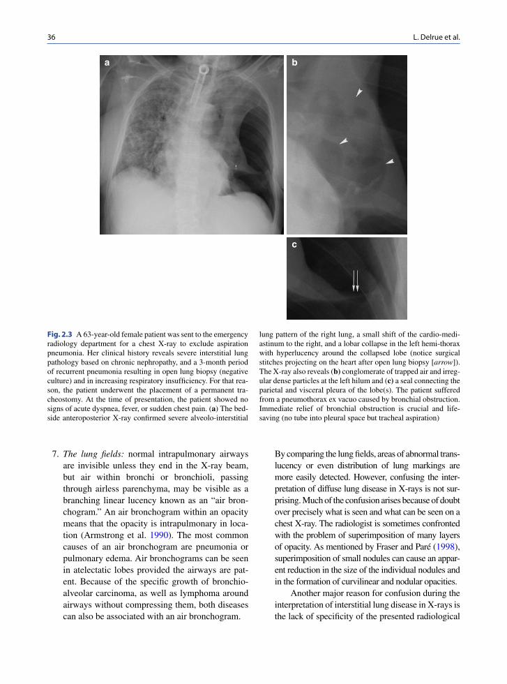
6. The pleura: the pleura consist of two thin layers covering a serous membrane lining the inside of the chest cavity and covering the lung, with a small amount of fluid in between. The pleura serves an important role in lung function; it acts as a cushion for the lungs and allows for smooth movement of the lungs within the chest cavity. It is not visible in normal conditions and barely visible in the case of ventral pleural detachment. The increase of the transparency of the lung can be very subtle or even masked by overlying tissue (Ball et al. 2005).Pay attention to pneumothorax “ex vacuo”; in this condition, acute bronchial obstruction from mucous plugs, aspirated foreign bodies, or badly positioned endotracheal tubes cause acute lobar collapse and a significant increase in negative intrapleural pressure around the collapsed lobe. As a consequence, gas is attracted into the pleural space around the collapsed lobe while the seal between the visceral and parietal pleura of the adjacent lobe or lobes remains intact. The remain-ing pleural attachment is characteristic. Correct interpretation of this kind of pneumothorax is cru-cial in directing treatment, which consists of relieving the bronchial obstruction rather than inserting a chest tube into the pleural space. Once the bronchial obstruction is relieved, the lobe will re-expand and the pneumothorax will resolve spontaneously (Ashizawa et al. 2001; Florman et al. 2001) (Fig. 2.3).
Other difficulties of pleural processes include determining whether a “pleural” abnormality really originates from the pleura (Fig. 2.4) and dis-tinguishing lung nodules from pleural irregulari-ties (Fig. 2.5).

352 Difficulties in the Interpretation of Chest Radiography
b
d
a
c
e f
g
Fig. 2.2 A 40-year-old female patient with chronic headaches consulted the hospital to exclude underlying general physical causes. She smokes 12 cigarettes a day. In this setting she received a chest X-ray. (a, b) Chest X-ray reveals a well-defined nodule projected alongside the heart at the right lung base on PA view and projected on the heart shadow on lateral view. Multi-detector row CT (MDCT) was performed to exclude neoplastic
nodule. (c, d) MDCT demonstrates a dense lobulated nodule in the anterior right lower lung lobe. (e, f) On the 3-dimensional reconstructions, the nodule is connected to a small artery and vein. No other parenchymal abnormalities are visualized. Final diagnosis was a pulmonary arterio-vascular malformation. (g) A digital magnified spot view of the chest X-ray reveals the vascu-lar malformation
36 L. Delrue et al.
7. The lung fields: normal intrapulmonary airways are invisible unless they end in the X-ray beam, but air within bronchi or bronchioli, passing through airless parenchyma, may be visible as a branching linear lucency known as an “air bron-chogram.” An air bronchogram within an opacity means that the opacity is intrapulmonary in loca-tion (Armstrong et al. 1990). The most common causes of an air bronchogram are pneumonia or pulmonary edema. Air bronchograms can be seen in atelectatic lobes provided the airways are pat-ent. Because of the specific growth of bronchio-alveolar carcinoma, as well as lymphoma around airways without compressing them, both diseases can also be associated with an air bronchogram.
By comparing the lung fields, areas of abnormal trans-lucency or even distribution of lung markings are more easily detected. However, confusing the inter-pretation of diffuse lung disease in X-rays is not sur-prising. Much of the confusion arises because of doubt over precisely what is seen and what can be seen on a chest X-ray. The radiologist is sometimes confronted with the problem of superimposition of many layers of opacity. As mentioned by Fraser and Paré (1998), superimposition of small nodules can cause an appar-ent reduction in the size of the individual nodules and in the formation of curvilinear and nodular opacities.
Another major reason for confusion during the interpretation of interstitial lung disease in X-rays is the lack of specificity of the presented radiological
a b
c
Fig. 2.3 A 63-year-old female patient was sent to the emergency radiology department for a chest X-ray to exclude aspiration pneumonia. Her clinical history reveals severe interstitial lung pathology based on chronic nephropathy, and a 3-month period of recurrent pneumonia resulting in open lung biopsy (negative culture) and in increasing respiratory insufficiency. For that rea-son, the patient underwent the placement of a permanent tra-cheostomy. At the time of presentation, the patient showed no signs of acute dyspnea, fever, or sudden chest pain. (a) The bed-side anteroposterior X-ray confirmed severe alveolo-interstitial
lung pattern of the right lung, a small shift of the cardio-medi-astinum to the right, and a lobar collapse in the left hemi-thorax with hyperlucency around the collapsed lobe (notice surgical stitches projecting on the heart after open lung biopsy [arrow]). The X-ray also reveals (b) conglomerate of trapped air and irreg-ular dense particles at the left hilum and (c) a seal connecting the parietal and visceral pleura of the lobe(s). The patient suffered from a pneumothorax ex vacuo caused by bronchial obstruction. Immediate relief of bronchial obstruction is crucial and life-saving (no tube into pleural space but tracheal aspiration)

372 Difficulties in the Interpretation of Chest Radiography
Fig. 2.4 A 37-year-old female patient was admitted to our hospi-tal with right latero-dorsal thoracic pain without history of a trau-matic event. There was no fever, weight loss, or nocturnal sweating. Clinical investigation revealed a painful hard mass at the right hemi-thorax; the lung auscultation was normal. The patient men-tioned recent travel to Australia. (a, b) Posteroanterior and lateral X-rays of the chest show a deformation of the dorsal costo-dia-
phragmatic sinus (arrows). (c) An oblique magnified view con-firmed the existence of the deformation: pleural mass? soft-tissue tumor? localized pleural effusion? (d) Contrast-enhanced Multi-detector row CT demonstrates a cystic lesion with dense rim in the right costophrenic pleura (white arrow) with expansion in the dor-sal thoracic wall (white arrowhead). Final diagnosis was a hyatid cyst (positive for Echinococcus antibodies)
a b
c

38 L. Delrue et al.
patterns. Basic radiological patterns of interstitial lung disease are reticular, nodular, reticulonodular, and linear, which are well known. However, some-times diseases present as reticular at the beginning and evolve into a nodular or mixed reticulonodular pattern. Similarly, in a reticular network, particu-larly if it is coarse, many linear densities will be seen “en face” and thus appear as a reticular pattern, but many must be seen on end and thus simulate nodules (Fraser et al. 1988; Stolberg et al. 1964). Because of this obvious visual effect, it might seem logical to designate all these diseases as reticu-lonodular (see Chap. 8: Interstitial Lung Disease).
However, the distinction between reticular and nodular is important not only morphologi-cally, but also in relation to the impact each may have on the pulmonary function (Fig. 2.6).
Unilateral pulmonary hyperlucency with decreased vascularity and airtrapping on expira-tion is signature of the Swyer-James-MacLeod syndrome (Lucaya et al. 1998) (Fig. 2.7).
8. The hidden areas: apices, posterior sulcus, medi-astinum, hila, and bones remain a challenge on chest X-rays, even in digital imaging, multi-detector row CT can be necessary for further differentiation (Fig. 2.8).
9. The hila: the dimension of the normal hila, delin-eated mostly by the large pulmonary arteries and upper lobe pulmonary veins, varies considerably within and among individuals (left versus right). A difference in the relative density of the two hila
a
b
Fig. 2.5 A 62-year-old male patient with a persistent cough was sent by his general physician for a chest X-ray to exclude lung pathology. The patient was a smoker but had no other items in his medical history. (a) Posteroanterior chest X-ray revealed a non-sharply delineated nodular structure of limited density projected on the posterior part of the sixth rib in the right hemi-thorax (arrow). A second fanciful dense opacity projected on the posterior part of the left sixth rib (arrow). (b) Linear densities projected posterior of the sternum and above the diaphragm, best revealed on the lateral chest X-ray (arrows). (c) Multi-detector row CT shows several pleural irregularities, e.g., at the level of the sixth rib bilateral. Some of the irregularities were partially calcified, specifically those located at the diaphragm. Irregular focal thickening of the pleura can simulate a suspicious parenchymal opacity on a chest X-ray
Fig. 2.4 (continued)

392 Difficulties in the Interpretation of Chest Radiography
could imply hilar pathology and is an indication for additional CT. A lack of sharpness of the lat-eral hilum also requires CT examination because of the implications of the silhouette sign. The hilum overlay and hilum convergence sign are based on that principle (Felson 1973) (Fig. 2.9).
10. Areas below the diaphragm: a pneumoperitoneum is more easily detected on a lateral chest X-ray in erect position than on an erect abdominal view. Chilaiditi syndrome, which is the interposition of the colon between the liver and diaphragm, is very common, especially among the elderly. The haustral pattern helps to distinguish it from free intraperitoneal gas.
c
Fig. 2.5 (continued)
a b c
Fig. 2.6 Several cases of parenchymal lucencies associated with the presence of cysts, which are difficult to distinguish on a conven-tional X-ray. (a, b) Pulmonary Langerhans cell histiocytosis. The X-ray reveals diffuse parenchymal lucencies and reticulonodular pattern of the interstitial space. High-resolution CT (HRCT) dem-onstrates cystic airspaces, which are mainly less than 10 mm in diameter, with typical sparing of the costophrenic angles. The lung cysts have distinct walls ranging from thin and barely perceptible to several millimeters in thickness and have varying shapes (mostly round, some bizarre in shape). (c, d) Lymphangioleiomyomatosis. The X-ray again reveals diffuse small parenchymal lucencies with a reticulonodular interstitial pattern. HRCT shows numerous thin-walled lung cysts with varying diameters (ranging from 2 mm to 5 cm) and round in shape, diffusely distributed and surrounded by patchy areas of ground-glass opacity. (e, f) Centrilobular emphy-sema. Only moderate to severe emphysema can be diagnosed on plain radiographs. The X-ray can only suggest parenchymal hyperlucency; perhaps reduction in the size of pulmonary vessels or vessel tapering can be detected. On HRCT there is the pres-ence of multiple small, round areas of abnormally low attenuation,
several millimeters in diameter. The areas of lucency are grouped near the centers of secondary pulmonary lobules, surrounding the centrilobular artery branches, and often lack distinct walls. (g, h) Panlobular emphysema. The X-ray reveals an increased hyperlu-cency with size reduction of pulmonary vessels and vessel taper-ing, which is not a sensitive or reliable sign of emphysema. HRCT demonstrates widespread areas of abnormally low attenuation by uniform destruction of the pulmonary lobule. The pulmonary vessels appear as fewer, smaller, and inconspicuous. Panlobular emphysema is easily distinguished from lung cysts by the lack of distinct walls. (i, j) Paraseptal emphysema. The X-ray shows no aberrancy in parenchymal pattern. On HRCT there are some focal hyperlucent areas in the subpleural areas (involvement of the distal part of the secondary lobule) with visible, very thin walls corre-sponding to the interlobular septae. (k, l) Fibrosis. The X-ray reveals a reticulonodular pattern with small nodular opacities. HRCT con-firms the reticulonodular pattern caused by subpleural intralobular interstitial thickening predominantly involving the subpleural lung regions, in combination with irregular opacities, honeycombing, architectural distortion, and traction bronchiectasis

40 L. Delrue et al.
g
j k l
h i
d e f
Fig. 2.6 (continued)

412 Difficulties in the Interpretation of Chest Radiography
a b
Fig. 2.7 (a) A chest X-ray of an 11-year-old child reveals a dis-crepancy in translucency between the left and the right hemitho-rax. Because of the asymmetric presentation of the lung fields, an overlaying interstitial or alveolar lung pathology cannot be excluded. There are no arguments for pneumothorax in the left hemithorax. Notice the tiny displacement of the mediastinum to the left side. (b) Multi-detector row CT shows a unilateral hyper-
lucent left lung with reduced lung volume in inspiration, dimin-uation of the vascularisation, and air-trapping. No disturbance of the interstitial or alveolar pattern can be seen. The patient suf-fered from Swyer-James-MacLeod syndrome, caused by incom-plete development of the alveolar buds as a result of damage to the terminal and respiratory bronchioles, usually due to viral lower respiratory tract infection in infancy or early childhood
11. Soft tissues: the breasts may partially obscure the lung bases. Physiological breast asymmetry or pre-vious surgery can mislead and be misinterpreted as parenchymal shadowing or hyperlucency. Identifi-cation of the nipple shadow is necessary to distin-guish from neoplasm and vice versa. Repeat X-rays with nipple marking or fluoroscopy can help out if in doubt.The anterior axillary fold frequently causes an ill-defined shadow on the lung fields and must be dif-ferentiated from a consolidation.
The caudal border of the opacity of the sterno-cleidomastoid muscles can simulate a cavity or bulla at the lung apices. Subpleural fat or prominent intercostal muscles can mimic pleural pathology.
12. Bones: bone alterations can be the only sign of pathology on chest X-rays; a fracture of the clavic-ula or fracture of the first rib can cause a pneumotho-rax and/or vascular rupture, both life-threatening situations. Hemi-vertebrae may be associated with neuro-enteric cysts.
As mentioned previously, more than 66% of the lung parenchyma is superimposed by bony struc-tures, which may result in missed lung nodules. On the other hand, focal bone opacities, such as a benign bone island (enostosis), also can result in false-positive abnormal chest X-rays (Fig. 2.10).
2.3.4 Evolution Over Time
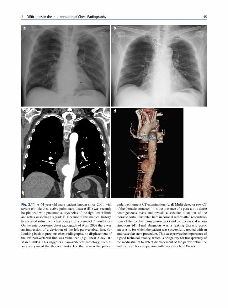
An additional source of information is the evolution over time. It is imperative to compare studies carried out at different dates whenever they are available (Fig. 2.11). A sudden or progressive increase in the cardio- mediastinal shadow width may be the only indicator of a mediastinal tumor. Minimal thickening of the right paratracheal stripe, which is an indirect sign of paratracheal lymphadenopathy, may be detected only when compared with a previous chest X-ray.

42 L. Delrue et al.
The speed of growth of a lesion over time indicates the cell replication rate within the lesion and gives information about its benign or malignant character. The rate of growth is disclosed by the doubling , or the time it takes a given tumor to double in volume, and requires sequential exposures over time (Garland et al.
1963). Tumor doubling time is an independent and sig-nificant prognostic factor for lung cancer patients (Usuda et al. 1994). Spratt et al (1963). found a mean doubling time of 3.1 months for squamous cell carci-noma, 9 months for adenocarcinomas, and 3 months for undifferentiated cancer on chest X-rays.
a
b
c d
Fig. 2.8 A 66-year-old male patient with ethylic liver cirrhosis was admitted to the hospital for diminished consciousness and deterioration of his general condition. (a) Posteroanterior and lateral view of the chest demonstrate vascular calcifications at the descending aorta, widening of the carina, and a dense peri-cardial mass near the right atrial border (arrow). (b) Two verte-bral collapses are also visualized on the lateral view: at the fifth
dorsal and first lumbar vertebra. (c) Nonenhanced multi-detector row CT confirms a relatively dense paraesophageal and para-aortic soft tissue structure. (d) T1-weighted magnetic resonance image after Gadolinium demonstrates a knot of vessels in the middle and posterior mediastinum. The pericardial mass visual-ized on the chest X-ray was periesophageal varices in this patient who has liver cirrhosis

432 Difficulties in the Interpretation of Chest Radiography
a b
dc
e
Fig. 2.9 A 56-year-old male patient consulted the hospital for persistent dry cough, dyspnea when exercising, asthenia, and weight loss despite a good appetite. History revealed nicotine abuse (25–30 pack years) and exposure to asbestos. (a, b) Chest X-ray suggests an additional opacity (arrows) at the left hilum, best visualized on the lateral view projected on the anterior border of the thoracic vertebral column. (c, d) Multi-detector row CT
confirms a homogeneous mass at the origin of the main bronchus of the left lower lobe, as illustrated here in coronal and lateral reformatted reconstructions of the mediastinum (arrows). (e) Positron emission tomography-CT shows elevated fludeoxyg-lucose uptake in the mass. Bronchoscopy confirmed a suspicious mass in the ostium of the bronchus of the left lower lobe. Pathology revealed a non–small-cell lung carcinoma, spinocellular type

44 L. Delrue et al.
Temporal subtraction may be the innovation that reveals a significant improvement in the accuracy of detection of nodules and hazy pulmonary opacities such as pneumonia and pneumonitis (Difazio et al. 1997; MacMahon et al. 2008b; Tsubamoto et al. 2002). This advanced image-processing technique enhances interval changes by using the previous radiographs as
subtraction masks (MacMahon et al. 2008a). DiFazio and others (1997) reported not only a substantial and highly significant improvement in diagnostic accuracy when using temporal subtraction, they also stated that the chest X-ray interpretation time was reduced by 19%. One of the difficulties of this technique is its dependence on reproducible patient positioning. The
a
c
d
b
Fig. 2.10 A 64-year-old male patient was sent to the emergency radiology department with spontaneous intracranial bleeding. He received surgical cranial decompression and a tracheostomy. (a) A bedside chest X-ray in the intensive care ward shows a dense nodular structure in the eighth intercostal space on the right side (arrow). (b) Digital magnified spot view confirms the nodular density with nonsharp margins (arrow). (c) Mutli-detector row
CT shows no parenchymal nodule on axial view in lung window. At the scapular point a nodular density is revealed (arrow) and confirmed on (d) the magnified spot reconstructed with bone window (arrow). This is an incidental finding of a solitary dense nodule on a chest X-ray in a patient with spontaneous intracra-nial bleeding. This nodule was located in the scapular point and consisted of dense osseous tissue (benign bony island)
452 Difficulties in the Interpretation of Chest Radiography
a b
c d
Fig. 2.11 A 64-year-old male patient known since 2001 with severe chronic obstructive pulmonary disease (III) was recently hospitalized with pneumonia, erysipelas of the right lower limb, and reflux oesophagitis grade B. Because of this medical history, he received subsequent chest X-rays for a period of 2 months. (a) On the anteroposterior chest radiograph of April 2008 there was an impression of a deviation of the left paravertebral line. (b) Looking back to previous chest radiographs, no displacement of the left paravertebral line was visualized (e.g., chest X-ray DD March 2008). This suggests a para-vertebral pathology, such as an aneurysm of the thoracic aorta. For that reason the patient
underwent urgent CT examination. (c, d) Multi-detector row CT of the thoracic aorta confirms the presence of a para-aortic dense heterogeneous mass and reveals a saccular dilatation of the thoracic aorta, illustrated here in coronal reformatted reconstruc-tions of the mediastinum (arrow in c) and 3-dimensional recon-structions (d). Final diagnosis was a leaking thoracic aortic aneurysm, for which the patient was successfully treated with an endovascular stent procedure. This case proves the importance of a good technical quality, which is obligatory for transparency of the mediastinum to detect displacement of the paravertebralline and the need for comparison with previous chest X-rays

46 L. Delrue et al.
majority of the artefacts in thoracic temporal subtrac-tion are due to bone misregistration, which can be reduced or even eliminated in combination with dual-energy imaging (see above).
Evolution over time can also make interpretation more difficult and complex. As diseases progress, identified patterns can disappear. Several lung dis-eases, each with a different diagnostic pattern, may all eventually evolve into lung fibrosis; all present the same pattern of honeycomb formation.
2.3.5 Knowledge of Clinical Presentation, History, and Correlation to Other Diagnostic Results
When there is no clinical information or medical history available, the exact diagnosis of a rounded peripheral
mass on plain chest X-ray can be very challenging because benign or malignant lesions, infection, rounded atelectasis (as seen in asbestosis), lung sequestration (Fig. 2.12), or congenital disorders such as broncho-genic cysts can be the responsible underlying disease.
Another example illustrating the unavoidable need for clinical information or medical history is acute lung fibrosis. Chemotherapy may induce acute lung fibrosis and can lead to respiration failure. Immediate chemotherapy interruption and oxygen support are mandatory.
Another difficulty relating to fibrosis is differentiat-ing fibrosis from an infectious disease in a patient with chronic obstructive pulmonary disease, as described in Fig. 2.13.
The integration of information obtained from sys-tematic interpretation of the chest X-ray and correla-tion with the clinical status often results in an allowable degree of diagnostic accuracy in chest diseases.
a b
c
Fig. 2.12 A 63-year-old male patient with cough, fever, and dyspnea. (a, b) PA and lateral chest X-ray reveals a right mediastinal shift, a mass projected on the right cardiac border, posteriorly located in the right lung lower lobe and associated with pleural thickening and obliteration of the cardiophrenic sinus. The hyperlucency of the retrosternal space on the lateral view is due to an asymmetry in expansion of both lungs and causing a distortion of the sternum (c) CT confirmed pleural effusion and thickening, right mediastinal shift, and the mass posteriorly located in the right lower lung. This rounded dense mass is swirled by vessels and bronchi converging upon the density (comet sign). Notice the presence of calcified pleural plaques on the diaphragm and flattening of the diaphragm. This patient was exposed to asbestos and was diagnosed with a rounded atelectasis

472 Difficulties in the Interpretation of Chest Radiography
2.4 Errors and Perception
2.4.1 Perceptual and Cognitive
The radiological diagnosis of chest disease begins with the identification of an abnormality on a chest X-ray; in other words, that which is not seen cannot be appreciated (Fraser et al. 1988). That appreciation is submitted to the perceptual and cognitive limitations that have a direct bearing on the clinical utility and effectiveness of chest X-rays (McAdams et al. 2006).
Experience gives the radiologist the perceptual and cognitive skills to know what information to look for and how to interpret that information based on the accumulation and integration of information pro-cessed from previous encounters with the same type of images (Krupinski 2003). What makes the task dif-ficult, is that, although the basic anatomy is essen-tially the same in all images, the degree of natural variation in both normal and abnormal structures is high and radiologists will never be able to see all pos-sible variations during their career. The results of all this variation in normal and abnormal features are variation and error in interpretation. Kundel et al
(1978). found that perceptual errors can be grouped into three general categories
Some missed lesions are never looked at.•Some missed lesions are looked at, but not long •enough to allow detection or recognition.Some lesions are looked at for long period of time •but either are not recognized as a lesion or are actively dismissed as normal structure.
2.4.2 Observer Errors
Observer errors provoke false-negative or false-posi-tive readings. In case of a false-positive reading, a find-ing without pathological significance is interpreted as a lesion; in case of a false-negative reading, a pathologi-cal finding is misinterpreted as normal. Inter-observer disagreement in some cases may reach astonishing lev-els (Fraser et al. 1988). Observer errors are very com-plex and every physician concerned with the correct reading and interpretation of a chest X-ray must also have proficient knowledge of the physical and physio-logical principles of perception, so errors will be
a b
Fig. 2.13 An 84-year-old male patient, 10 years after coronary artery bypass graft, was admitted with dyspnea and cough, pres-ent during the last 2 months. (a) A routine PA chest X-ray revealed a reticulo-nodular pattern of the parenchyma of both lungs and enlargement of the trachea. Differential diagnosis included fibrosis, pneumonia, or co-morbidity of fibrosis and
pneumonia. (b) High-resolution CT demonstrates massive fibro-sis with dilatation of bronchi and bronchioles, accentuation of the interlobular septae, peripheral honeycombing, and ground-glass opacity as a sign of active fibrosis. There were no argu-ments for associated bacterial pneumonia

48 L. Delrue et al.
diminished to a minimum. It is important to read chest X-rays from a certain distance, at least 6–8 ft, both because the slight nuances of density variation between similar zones can be better detected at a distance and because the visibility of shadows with ill-defined mar-gins is improved with minification (Fraser et al. 1988). This was previously discussed by Tuddenham in 1963 (Tuddenham 1963). Shea and Ziskin (1972) mentioned that reading X-rays at a fixed distance increases the risk of failure of abnormality detection.
Another mechanism to reduce the frequency of mis-reading X-rays is double reading: dual interpretation by the same observer on two separate occasions or by two independent observers. This procedure improves the diagnostic accuracy, but is difficult to implement routinely in large radiology departments (Fraser et al. 1988). However, since double reading improves sensi-tivity, Stitik et al. recommend to double read a chest X-ray by removing the eyes from the image for a short period and looking at it a second time before finalizing the report (Stitik and Tockman 1978).
Psychological aspects in interpretation should also be mentioned as a source of errors when reading chest X-rays. No experienced radiologist can deny the dimi-nution in visual and mental acuity when exposed to a heavy work load, the so called “reader fatigue.” Errors owing to reader fatigue can be reduced through fre-quent “rest periods” away from the viewbox and a rea-sonable work load each day. Attention to comfort and convenience in the viewing facilities, e.g., light inten-sity, background illumination, and noise, reduces the risk of interpretation failure. Intra-observer disagree-ments are also bound to occur, probably ascribed to “a state of mind” that is continually fluctuating, and they represent an intangible influence on one’s approach to a problem (Fraser et al. 1988). Satisfaction of search is also a source of errors in reading chest X-rays: under-reading errors (false-negative responses) occur when lesions remain undetected after detection of an initial lesion (Berbaum et al. 1990).
2.5 Radiologic Report
The radiologic report should be built up in two parts: a descriptive part and a conclusive part (Westra 1990).
Lesions must be depicted in the descriptive part in such a way that the conclusion can be anticipated
(Westra 1990). It is mandatory that, in the conclusive part, an attempt be made to answer the specific ques-tions that were the reason for performing the examina-tion and to guide the clinician toward possible further procedures or examinations when necessary.
Words must be carefully chosen. The Fleischner Society, whose purpose is to advance knowledge of the normal and diseased chest, proposed the “Glossary of terms of thoracic radiology” (Hansell et al. 2008; Tuddenham 1984) to standardize terms so exchange of information would be facilitated. This glossary helps to identify nuances of meaning that distinguish words of similar connotation and to reject the argument that “everyone says it that way” as a justification for a mis-used term. The term “infiltrate” is almost invariably used in the sense of any poorly defined opacity in the lung, and serves no useful purpose. Due to the lack of any specific connotation, it causes great confusion. It should only be used as a descriptor to distinguish pro-cesses that do not distort the lung architecture from expanding processes that do (Tuddenham 1984).
There is also considerable variation in the terms used for describing pulmonary “dense” structures.
The term “opacity” in a radiograph refers to any area that appears more opaque (or of lesser photomet-ric density) than its surroundings. It is an essential and recommended radiologic descriptor that does not indi-cate the size or pathologic nature of the abnormality (Hansell et al. 2008).
The term “nodule” is any pulmonary or pleural lesion represented in a radiograph by a well or poorly defined, discrete, nearly circular opacity of 2–30 mm in diameter and is a descriptor recommended to be always qualified with respect to size, location, border characteristics, number, and opacity (Hansell et al. 2008; Tuddenham 1984).The term “micronodule” is reserved for a sharply defined, discrete, nearly circular opacity of less than 3 mm in diameter. “Mass” is used if the opacity is larger than 30 mm in diameter (Hansell et al. 2008; Tuddenham 1984).
Every radiologist must be thoughtful in his or her choice of words; not only is visualizing the disease a basic condition for medical treatment, but so is the right description of this visualization.
In conclusion, despite the long existence of conven-tional radiography, which is based on the inherent con-trast of the connecting components in the thorax (soft tissue – bone – air – fat), and despite the development of newer and more exciting imaging techniques, chest

492 Difficulties in the Interpretation of Chest Radiography
X-ray still remains one of the most challenging diag-nostic tools due to the wide range of possible diseases, especially when performed in the approved manner with all the trimmings.
References
Armstrong P, Wilson AG, Dee P (1990) Imaging of diseases of the chest. Mosby – Year Book, London
Ashizawa K, Hayashi K, Aso N et al (2001) Lobar atelectasis: diagnostic pitfalls on chest radiography. Br J Radiol 877:89–97
Austin JHM, Romney BM, Goldsmith LS (1992) Missed Bronchogenic-Carcinoma – radiographic findings in 27 patients with a potentially resectable lesion evident in retro-spect. Radiology 1:115–122
Bacher K, Smeets P, De Hauwere A et al (2006) Image quality performance of liquid crystal display systems: influence of display resolution, magnification and window settings on contrast-detail detection. Eur J Radiol 3:471–479
Ball CG, Kirkpatrick AW, Laupland KB et al (2005) Factors related to the failure of radiographic recognition of occult posttraumatic pneumothoraces. Am J Surg 5:541–546
Berbaum KS, Franken EA Jr, Dorfman DD et al (1990) Satisfaction of search in diagnostic radiology. Invest Radiol 2:133–140
Bogaert J, Verschakelen J (1995) Spiral CT of the diaphragm. J Belge Radiol 2:86–87
Boynton RM, Bush WR (1956) Recognition of forms against a complex background. J Opt Soc Am 9:758–764
Brogdon BG, Kelsey CA, Moseley RD Jr (1983) Factors affect-ing perception of pulmonary lesions. Radiol Clin North Am 4:633–654
Busch HP (1997) Digital radiography for clinical applications. Euro Radiol 7(suppl 3):S66–S72
Chen JT (1983) The plain radiograph in the diagnosis of cardio-vascular disease. Radiol Clin North Am 4:609–621
Difazio MC, MacMahon H, Xu XW et al (1997) Digital chest radiography: effect of temporal subtraction images on detec-tion accuracy. Radiology 2:447–452
Felson B (1973) Chest roentgenology. WB Saunders, PhiladelphiaFlorman S, Young B, Allmon JC et al (2001) Traumatic pneu-
mothorax ex vacuo. J Trauma 1:147–148Fraser RG, Paré JAP, Paré PD et al (1988) Diagnosis of diseases
of the chest. WB Saunders, PhiladelphiaGarland LH, Coulson W, Wollin E (1963) The rate of growth
and apparent duration of untreated primary bronchial carci-noma. Cancer 16:694–707
Hansell DM, Bankier AA, MacMahon H et al (2008) Fleischner society: glossary of terms for thoracic imaging. Radiology 3:697–722
Ishigaki T, Sakuma S, Horikawa Y et al (1986) One-shot dual-energy subtraction imaging. Radiology 1:271–273
Krupinski EA (2003) The future of image perception in radiology: synergy between humans and computers. Acad Radiol 1:1–3
Kundel HL, Nodine CF (1983) A visual concept shapes image perception. Radiology 2:363–368
Kundel HL, Nodine CF, Carmody D (1978) Visual scanning, pattern recognition and decision-making in pulmonary nod-ule detection. Invest Radiol 3:175–181
Lucaya J, Gartner S, Garcia-Pena P et al (1998) Spectrum of manifestations of Swyer-James-MacLeod syndrome. J Comput Assist Tomogr 4:592–597
MacMahon H, Li F, Engelmann R et al (2008a) Dual energy subtraction and temporal subtraction chest radiography. J Thorac Imaging 2:77–85
MacMahon H, Li F, Engelmann R et al (2008b) Dual energy subtraction and temporal subtraction chest radiography. J Thorac Imaging 2:77–85
McAdams HP, Samei E, Dobbins J 3rd et al (2006) Recent advances in chest radiography. Radiology 3:663–683
Mettler F, Ringertz H, Vañó E (2004) Managing patient dose in digital radiology: a report of the International Commission on Radiological Protection. Ann ICRP 1:1–73
Meyers BF, McCabe CJ (1993) Traumatic diaphragmatic hernia Occult marker of serious injury. Ann Surg 6:783–790
Milne EN (1993) Reading the chest radiograph. A physiologic appraoch. Mosby – Year Book, St Louis
Murfitt J (1993) The normal chest: methods of investigation and differential diagnosis. Churchill Livingstone, Oxford
Nitrosi A, Borasi G, Nicoli F et al (2007) A filmless radiology department in a full digital regional hospital: Quantitative evaluation of the increased quality and efficiency. J Digit Imaging 2:140–148
Novelline RA, Squire LF (1997) Squire’s fundamentals of radi-ology. Harvard University Press, Cambridge
Shea FJ, Ziskin MC (1972) Visual system transfer function and optimal viewing distance for radiologists. Invest Radiol 3:147–151
Shephard CT (2003) Radiographic image production and manip-ulation. McGraw-Hill Columbus, Ohio
Spratt JS Jr, Spjut HJ, Roper CL (1963) The frequency distribu-tion of the rates of growth and the estimated duration of pri-mary pulmonary carcinomas. Cancer 16:687–693
Squire LF (1970) Exercises in diagnostic radiology. WB Saunders, Philadelphia
Stitik FP, Tockman MS (1978) Radiographic screening in the early detection of lung cancer. Radiol Clin North Am 3:347–366
Stolberg HO, Patt NL, Macewen KF et al (1964) Hodgkin’s disease of the lung. Roentgenologic-pathologic correlation. Am J Roentgenol Radium Ther Nucl Med 92:96–115
Swallow RA, Naylor E, Roebuck EJ et al (1986) Clark’s posi-tioning in radiography. Heinneman Medical Books, Oxford
Tsubamoto M, Johkoh T, Kozuka T et al (2002) Temporal subtraction for the detection of hazy pulmonary opacities on chest radiography. Am J Roentgenol 179(2): 467–471
Tuddenham WJ (1963) Problems of perception in chest rontgen-ology: facts and fallacies. Radiol Clin North Am 1:277
Tuddenham WJ (1984) Glossary of terms for thoracic radiology: recommendations of the Nomenclature Committee of the Fleischner Society. AJR Am J Roentgenol 3:509–517
Usuda K, Saito Y, Sagawa M et al (1994) Tumor doubling time and prognostic assessment of patients with primary lung cancer. Cancer 8:2239–2244
Westra D (1990) Radiologic diagnosis of chest disease. Springer, Berlin
Wright FW (2002) Radiology of the chest and related condi-tions. Taylor and Francis, London

http://www.springer.com/978-3-540-79941-2