
DIAL FACILITIES MANAGEMENT PRACTICES …etler.com/docs/DFMP/H/DFMP-H-6r(2)_I1.pdf · dial...
32
DIAL FACILITIES MANAGEMENT PRACTICES AT & TCo Standard DIVISION H SECTION 6r(2) Issue 1, December 1976 1. 2. 3. 4. 5. 6. 7. 8. SWITCHING SYSTEMS MANAGEMENT NO. 1 ELECTRONIC .SWITCHING SYSTEM (2-WIRE) CENTREX ADMINISTRATION CONTENTS PAGE CONTENTS INTRODUCTION 2 ABBREVIATED CLASS CODES CENTREX SERVICE 2 9. PROBLEM ANALYSIS SIMULATED PBX SERVICE 2 PROBLEM DETERMINATION EQUIPMENT 3 TRANSLATION PROBLEMS CENTREX 3 BLOCKAGE PAGE 9 9 9 9 10 A. Centrex Service With Data Link Hardware PROBLEM ANALYSIS AND CORRECTIVE 3 ACTION B. Centrex Service Without Data Link 10. SPECIAL REQUIREMENTS Hardware 4 DIVISION OF REVENUE SIMULATED PBX 5 LINE ASSIGNMENT A. Simulated PBX Service With Data Link Hardware 5 NUMBER ASSIGNMENT B. Simulated PBX Service Without Data INTERCEPT ARRANGEMENTS Link Hardware 5 BUSINESS SERVICE/ MARKETING REQUIRE- CENTREX FEATURES 5 MENTS CENTREX PLANNING 6 11. REFERENCES CENTREX TRANSLA liONS 7 TRAFFIC MEASUREMENTS 8 Figures CENTREX TRAFFIC REGISTERS 8 1. Centrex or Simulated PBX System With Centrex Data Link Hardware RELATED TRAFFIC REGISTERS 8 2. Centrex or Simulated PBX System Without GROWTH 8 Centrex Data Link Hardware TRANSLATION GROWTH PROCESS 8 3. Centrex System (AIOD Configuration) NOTICE Not for use or disclosure outside the Bell System except under written agreement 10 10 10 10 11 11 12 12 13 14 15 006-164 Printed in U.S.A. Page 1
Transcript of DIAL FACILITIES MANAGEMENT PRACTICES …etler.com/docs/DFMP/H/DFMP-H-6r(2)_I1.pdf · dial...
DIAL FACILITIES MANAGEMENT PRACTICES AT & TCo Standard
DIVISION H SECTION 6r(2)
Issue 1, December 1976
1.
2.
3.
4.
5.
6.
7.
8.
SWITCHING SYSTEMS MANAGEMENT
NO. 1 ELECTRONIC .SWITCHING SYSTEM (2-WIRE)
CENTREX ADMINISTRATION
CONTENTS PAGE CONTENTS
INTRODUCTION 2 ABBREVIATED CLASS CODES
CENTREX SERVICE 2 9. PROBLEM ANALYSIS
SIMULATED PBX SERVICE 2 PROBLEM DETERMINATION
EQUIPMENT 3 TRANSLATION PROBLEMS
CENTREX 3 BLOCKAGE
PAGE
9
9
9
9
10
A. Centrex Service With Data Link Hardware PROBLEM ANALYSIS AND CORRECTIVE 3 ACTION
B. Centrex Service Without Data Link 10. SPECIAL REQUIREMENTS Hardware 4
DIVISION OF REVENUE SIMULATED PBX 5
LINE ASSIGNMENT A. Simulated PBX Service With Data Link
Hardware 5 NUMBER ASSIGNMENT
B. Simulated PBX Service Without Data INTERCEPT ARRANGEMENTS Link Hardware 5
BUSINESS SERVICE/ MARKETING REQUIRE-CENTREX FEATURES 5 MENTS
CENTREX PLANNING 6 11. REFERENCES
CENTREX TRANSLA liONS 7
TRAFFIC MEASUREMENTS 8 Figures
CENTREX TRAFFIC REGISTERS 8 1. Centrex or Simulated PBX System With Centrex Data Link Hardware
RELATED TRAFFIC REGISTERS 8 2. Centrex or Simulated PBX System Without
GROWTH 8 Centrex Data Link Hardware
TRANSLATION GROWTH PROCESS 8 3. Centrex System (AIOD Configuration)
NOTICE Not for use or disclosure outside the
Bell System except under written agreement
10
10
10
10
11
11
12
12
13
14
15
006-164 Printed in U.S.A. Page 1
SECTION 6r(2)
CONTENTS PAGE
4. Centrex and PBX Feature Packages 16
5. No. 1 ESS Centrex Translation and Cutover Data 17
6. Centrex Task Sequence List 28
7. Centrex Translation Forms 30
8. Centrex Intercept Considerations 32
1. INTRODUCTION
1.01 Centrex service is a telecommunication switching arrangement provided for the
benefit of an individual or private organization and is sometimes referred to as centrex customer group service. The service includes facilities for interconnecting telephones within a customer group and for connecting those telephones to other telephones associated with the central office, other central offices, and other centrex customer groups. It is distinguished from private branch exchange (PBX) service in that it provides for direct inward dialing (DID) and identified outward dialing for its stations.
1.02 When this section is reissued, this paragraph will contain the reason for reissue.
1.03 The title of each figure includes a number(s) in parentheses which identifies the paragraph(s)
in which the figure is referenced.
1.04 The network administrator is responsible for the translation, data acquisition, and
administration of the No. 1 Electronic Switching System (ESS) office providing centrex service. This section therefore describes centrex service for the No. 1 ESS, the various methods of providing service to the customer, and the equipment arrangements required. Also provided is information pertaining to the planning for, translation of, and supervision required for new and existing centrex groups.
1.05 In the future, centrex customer group service may be replaced by ESS Exchange (ESSX)
service. This practice may be reissued to reflect the new ESSX service offering or a new practice may be issued.
2. CENTREX SERVICE
2.01 Centrex service originates from a No. 1 ESS central office which has been equipped with
a centrex (CTX) type generic program. A maximum of 2047 centrex customer groups as well as basic
Page 2
telephone subscribers may be served by this office. All switching equipment required to serve the centrex group(s) is within the No. 1 ESS switching machine and is located on operating telephone company premises. Centrex customers' lines are directly connected to the central office in the same manner as regular telephone subscriber lines are connected (plain old telephone service [POTS]). Each centrex line therefore has an equipment appearance at the central office and has direct access to the switching facilities. This type of centrex service is commonly referred to as centrex-CO.
2.02 In addition to individual centrex station lines, each centrex group may be provided with
one or more 27A- or 47A-type telephone consoles. Association of the consoles with the central office is made via attendant trunks while console key and lamp data are transmitted back and forth between the console and central office via a console data loop.
2.03 Since each centrex line has an appearance at the central office, calls originating or
terminating at centrex stations are switched through the network in the same manner as calls are connected for POTS customers. This is also true of calls involving the attendant. Centrex programs and translations at the No. 1 ESS, to which the customer group is connected, indicate which subscriber lines are part of a centrex customer group and determine the treatment the subscriber lines receive.
2.04 A variation of the centrex service described in 2.01 through 2.03 utilizes switching
equipment located on the customer's premises. Switching equipment may be step-by-step, crossbar, or electronic working in conjunction with a No. 1 ESS office for in and out traffic. This service may include automatic identified outward dialing (AIOD) when PBX-automatic number identification (ANI) equipment is installed at the remote location. This type of service has been commonly referred to as centrex-CU.
SIMULATED PBX SERVICE
2.05 PBX service traditionally has been provided utilizing switching equipment located on the
customer's premises but can now be provided on a central-office basis. This service, in general, is not very different from regular PBX service with
the exception that the No. 1 ESS uses its centrex translation program capability to simulate PBX service. This type of service has been commonly referred to as PBX-CO.
2.06 All station lines are connected over outside plant facilities directly into the central office
in the same manner as they are connected for centrex service. The basic difference between this service and centrex service is that centrex stations are allowed to receive DID calls whereas in a simulated PBX environment all incoming calls are directed to the attendant. A second major difference is that PBX outward-dialed calls are not station-identified for charging purposes. A third difference is that there is a maximum quantity of calls that a simulated PBX customer can have in progress at any one time with the local message network (depending on the number of one-way and 2-way trunks the PBX customer has purchased) whereas the centrex customer has no such restriction. Centrex translations are used to apply the DID and direct outward dialing (DOD) station restrictions.
Note: The term "trunk" does not constitute a physical facility. Rather, the one-way and 2-way physical trunk facility, such as traditional PBX systems use to limit (regulate) calls, is simulated by No. 1 ESS simulated facilities group (SFG) feature translations.
3. EQUIPMENT
CENTREX
3.01 Centrex service may be offered to a customer either with or without centrex data link
hardware.
A. Centrex Service With Data link Hardware
3.02 Each centrex customer being provided centrex service with data link hardware is equipped
with one or more 1B, 27A, 2B, or 47A type universal cordless telephone consoles to provide attendant services. The 27A- and 47A-type are intended to replace the 1B and 2B type respectively.
3.03 A centrex data loop interconnects the attendant telephone consoles at the customer's
premises with the 2-wire No. 1 ESS central office. This loop is a peripheral unit which provides 2-way data communications between the central office and the attendant consoles. This loop transmits
ISS 1, SECTION 6r(2)
lamp data to the attendant consoles in order to control the states of lamps on the consoles which indicate service requests or other supervisory signals to the attendant. The data loop also transmits key signals from the attendant consoles to the central office. These key signals are interpreted at the ESS central office as requests for specific actions at the central office. One data loop circuit is capable of controlling a maximum of four of the 27A-type or four of the 47A-type attendant consoles. With some system arrangements, a data loop circuit may control only three of the consoles.
3.04 Each centrex customer group is assigned a listed directory number (LDN). All calls to
the LDN are routed, in the order of their arrival, to an attendant associated with that particular customer group.
3.05 Call distribution is provided to spread the load evenly to all attendants and to prevent
a new call from being switched to a console before the attendant is ready to answer it.
3.06 Centrex stations may be equipped with either TOUCH-TONE® or rotary dial telephones.
The 27A- and 47A-type attendant consoles are TOUCH-TONE equipped.
3.07 Centrex service requires the use of two additional specialized equipment units other
than the attendant telephone consoles and the station telephones:
• A centrex data link frame provided at the ESS central office
• A centrex console control cabinet installed at the centrex customer-group premises.
These units are used to implement the data transmission between the centrex customer location and the central office.
3.08 Certain trunk circuits, such as those for tie trunks, may be assigned for the exclusive
use of a particular centrex customer group or centrex complex. These circuits are used to connect the particular centrex group or complex to other switching systems. These circuits are terminated in the ESS central office in the same manner as other trunks are terminated; however, through the ESS stored memory, the system is aware that
Page 3
SECTION 6r(2)
these trunks are to be used only by a particular centrex customer group or centrex complex.
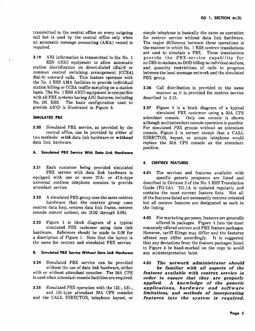
3.09 Figure 1 is a block diagram of a typical centrex customer using data link hardware.
Only one console is shown although on larger centrex installations additional consoles may be provided to handle greater attendant traffic. The centrex station telephones are connected directly to the line link network in the same manner as noncentrex subscribers' telephones are connected. The attendant trunk circuit connects to the trunk link network to provide a talking path for the attendant via an attendant loop circuit. Each attendant console is equipped with up to six loop circuits. These loop circuits give the attendant voice access to calls associated with the consoles. If all attendants are busy, calls are queued and routed to the first attendant which becomes idle. If the queue is exceeded (greater than four calls per console) busy tone is returned to the calling party. Only one attendant trunk is provided for each attendant telephone console since an attendant can process only one call at a time. The data loop which is illustrated provides the 2-way data path. The system is controlled by the 2-wire No. 1 ESS central processor. Tie trunks and foreign exchange (FX) trunks through which a centrex customer group may have access to other switching systems connect to the trunk link network.
B. Centrex Service Without Data link Hardware
3.10 Centrex service can be provided without the use of data link hardware either with
or without attendant consoles. The 50A Customer Premise System (CPS) is used when attendant console facilities are required.
3.11 The 50A CPS consists of attendant console(s) and modular panels located on the customer's
premises which provide supervision and control of the attendant position.
3.12 Three types of 50A CPS attendant consoles which may be used with centrex service are
as follows:
(a) 121-Type: Nondirect station selection
(b) 131-Type: 100-station attendant direct station selection (DSS) with busy lamp field
Page 4
(c) 151-Type: 200-station attendant DSS with busy lamp field.
3.13 When attendant consoles are not required, the following positions may be used to handle
the limited attendant functions:
(a) CALL DIRECTOR®
(b) Telephone keyset
(c) Simple telephone.
3.14 In both cases, either with or without attendant consoles, all customer station lines, including
the attendant position, are connected over outside plant facilities directly into the central office line link network. Conventional centrex data link hardware, and therefore data loops, are not required using the 50A CPS attendant consoles or the CALL DIRECTOR/telephone keyset/simple telephone. Instead, the attendant positions have direct line appearances (referred to as loops). The attendant position(s) utilizes the call-transfer feature to complete attendant-directed calls.
3. 15 Call distribution is provided to spread the load evenly to all 50A CPS consoles or to
CALL DIRECTOR, telephone keyset, or simple telephone attendant positions by utilizing the uniform call distribution feature. Uniform call distribution provides equal distribution of incoming traffic to the terminal numbers (attendant loops) in the multiline hunting group.
3. 16 Trunk circuits can also be assigned for the exclusive use of a centrex customer as with
27A- and 47A-type attendant console operation.
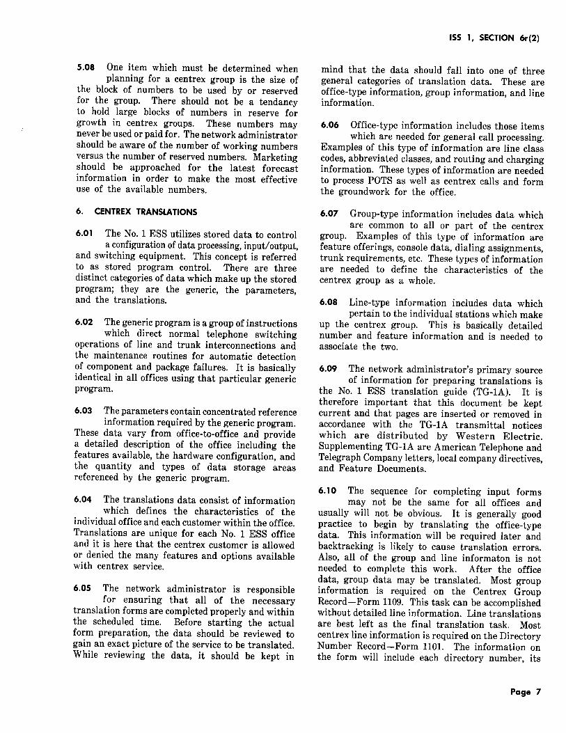
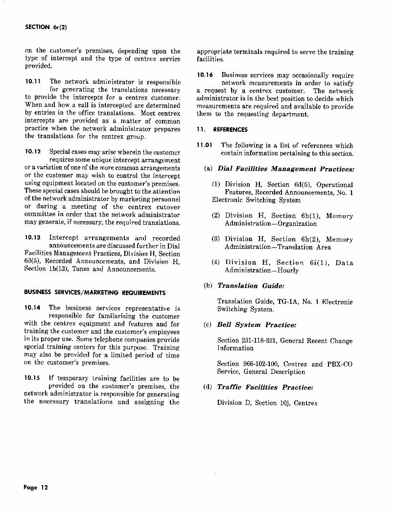
3. 17 Figure 2 is a block diagram of a typical centrex customer using a 50A CPS attendant
console. Only one console is shown, although multiattendant console operation is possible. For centrex groups without an attendant console, Figure 2 is correct except that a CALL DIRECTOR, telephone keyset, or simple telephone would replace the 50A CPS console as the attendant position.
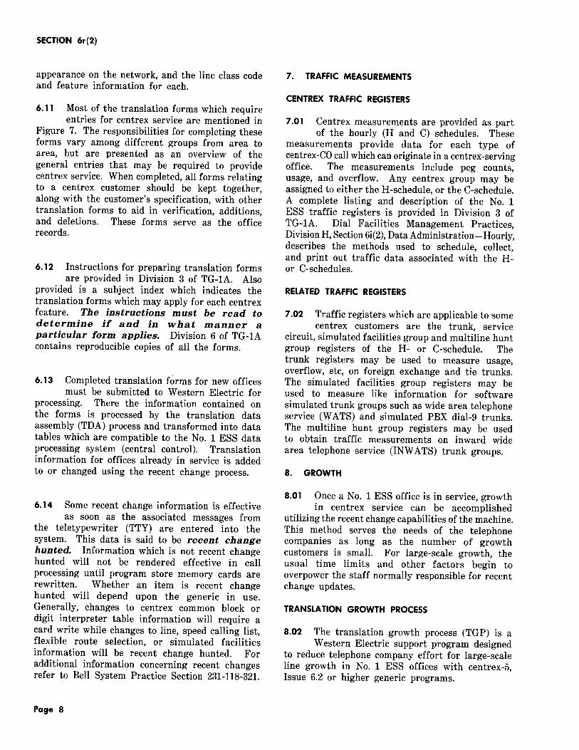
3.18 Centrex service as described in 2.04 utilizes ANI equipment at the customer location to
determine the station number originating the call and the number of the trunk on which the call went out and transmits these data to the central office over a data link circuit. ANI information is
transmitted to the central office on every outgoing call but is used by the central office only when an automatic message accounting (AMA) record is required.
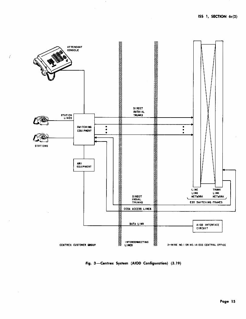
3.19 ANI information is transmitted to the No. 1 ESS AIOD equipment to allow automatic
station identification on direct-dialed (dial-9 or common control switching arrangement [CCSA] dial-8) outward calls. This feature operates with the No. 1 ESS AMA facilities to provide individual station billing or CCSA traffic sampling on a station basis. The No. 1 ESS AIOD equipment is compatible with all PBX systems having ANI features, including No. 101 ESS. The basic configuration used to provide AIOD is illustrated in Figure 3.
SIMULATED PBX
3.20 Simulated PBX service, as provided by the central office, can be provided by either of
two methods: with data link hardware or without data link hardware.
A. Simulated PBX Service With Data Link Hardware
3.21 Each customer being provided simulated PBX service with data link hardware is
equipped with one or more 27A- or 47A-type universal cordless telephone consoles to provide attendant service.
3.22 A simulated PBX group uses the same centrex hardware that the centrex group uses:
centrex data loop, centrex data link frame, centrex console control cabinet, etc (3.02 through 3.()8).
3.23 Figure 1 is block diagram of a typical simulated PBX customer using data link
hardware. Reference should be made to 3.09 for a description of Figure 1. Note that the layout is the same for centrex and simulated PBX service.
B. Simulated PBX Service Without Data Link Hardware
3.24 Simulated PBX service can be provided without the use of data link hardware, either
with or without attendant consoles. The 50A CPS is used when attendant console facilities are required.
3.25 Simulated PBX operation with the 121-, 131-, and 151-type attendant 50A CPS consoles
and the CALL DIRECTOR, telephone keyset, or
ISS 1, SECTION 6r(2)
simple telephone is basically the same as operation for centrex service without data link hardware. The major difference between these operations is the manner in which No. 1 ESS centrex translations are used to simulate a PBX. These translations provide the PBX-service capability for no-DID-to-stations, no-DOD-billing-to-individual-stations, and quantity restrictions of calls in progress between the local message network and the simulated PBX group.
3.26 Call distribution is provided in the same manner as it is provided for centrex service
described in 3.15.
3.27 Figure 2 is a block diagram of a typical simulated PBX customer using a 50A CPS
attendant console. Only one console is shown although multiattendant console operation is possible. For simulated PBX groups without an attendant console, Figure 2 is correct except that a CALL DIRECTOR, keyset, or simple telephone would replace the 50A CPS console as the attendant position.
4. CENTREX FEATURES
4.01 The services and features available with specific generic programs are listed and
described in Division 2 of the No. 1 ESS Translation Guide (TG-1A). TG-1A is updated regularly and contains the most current feature lists. Not all of the features listed are necessarily centrex-oriented but all centrex features are designated as such in the listing.
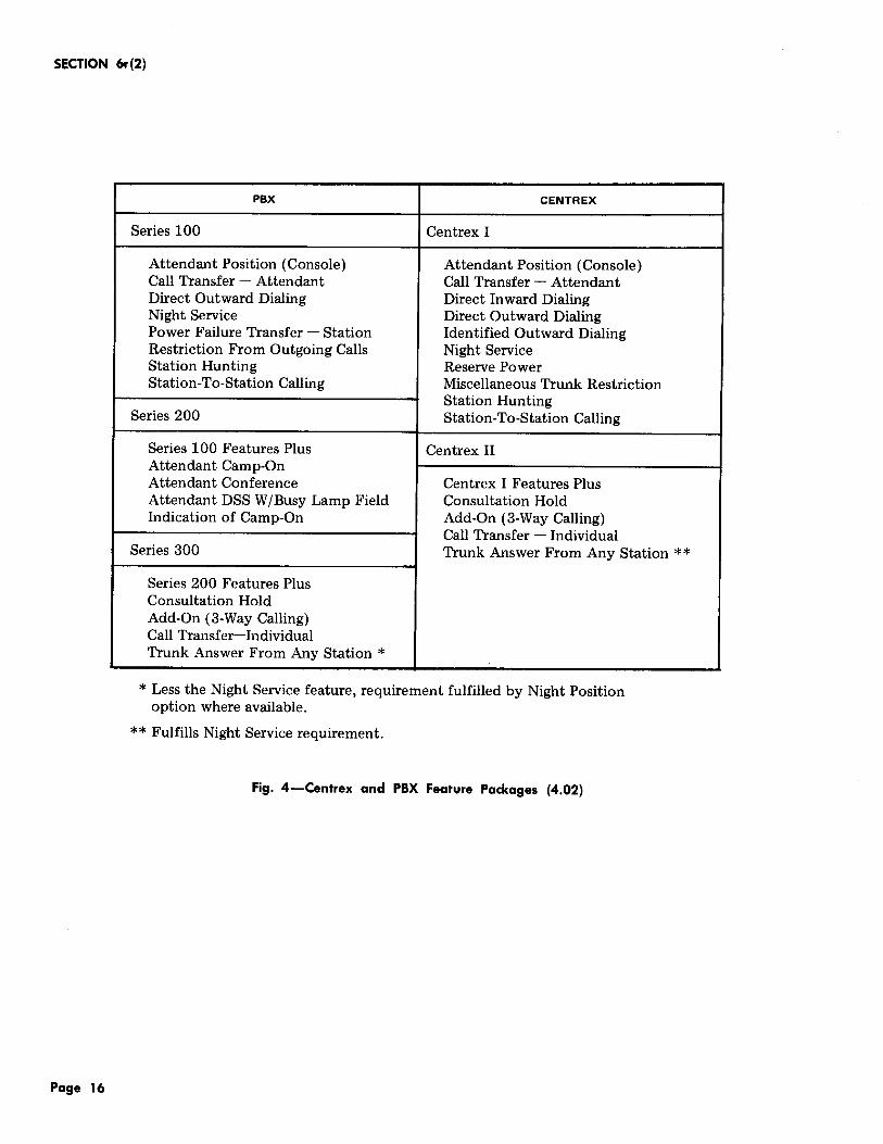
4.02 For marketing purposes, features are generally offered in packages. Figure 4 lists the most
commonly offered centrex and PBX feature packages. However, tariff filings may differ and the features offered may differ accordingly. It is suggested that any deviations from the feature packages listed in Figure 4 be hand-marked on the copy to avoid any misinterpretation later.
4.03 The network administrator should be familiar with all aspects of the
features available with centrex service in order to ensure that they are properly applied. A knowledge of the generic applications, hardware and software limitations, and methods of incorporating features into the system is required.
Page 5

SECTION 6r(2)
Specific information by feature is available in the No. 1 ESS Feature Documents.
4.04 Features are allowed or denied to a centrex customer by making appropriate entries in
the centrex translations. This task requires both planning and forecasting with regard to the customer's desires and needs. Centrex planning and translations are discussed in Parts 5 and 6.
5. CENTREX PLANNING
5.01 Planning the service for a prospective centrex group requires coordination within and
between a number of departments. It is recommended that a committee be formed to be responsible for the planning, activity, and cutover of all centrex service. This committee may be called the centrex cutover committee, the centrex planning team, or a similar name which implies its task. Each telephone company department which is involved in the centrex cutover should be represented on the committee.
5.02 The first contact between the telephone company and a prospective centrex customer
is usually made by a marketing representative. The marketing representative should obtain sufficient information describing the customer's service requirements. This information is passed to the centrex committee to establish the compatibility of the prospective service and the central office. Compatibility must be established in both software and hardware areas, eg, memory space, directory numbers, 6 port conference circuits, customer digit receivers (dial pulse versus TOUCH-TONE), etc.
5.03 Once it has been determined that the central office can serve the customer, the centrex
committee may meet to establish a cutover schedule and to assign each department its respective tasks. By this time, a cutover date should have been tentatively agreed upon by the customer and the marketing representative. Using that target date, the committee assigns tasks and schedules to each department through its committee representatives. When these assignments have been made, the cutover schedule is established and all parties concerned are made aware of their responsibilities for the cutover.
5.04 In order to simplify the scheduling and assigning of tasks, it is common practice
for the centrex committee to generate a memorandum
Page 6
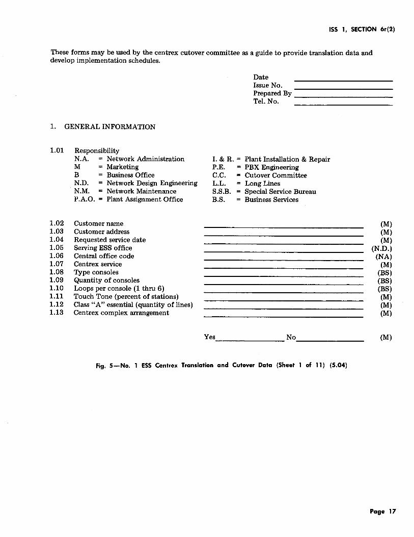
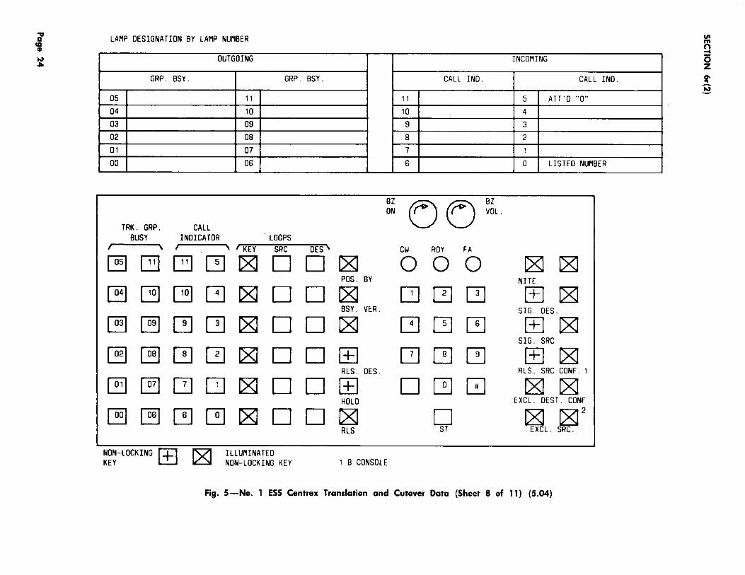
or data sheet(s) which indicates all facts and figures pertinent to the cutover of the centrex group. One example of a centrex cutover memorandum is shown in Figure 5. The memorandum contains entries for pertinent centrex information. The first entries made on the memorandum may be made by the marketing representative and as the job progresses the entries are updated with changes or additions to keep the information current. The major portion of this information should be completed approximately ten months before the cutover of a new No. 1 ESS office and six months before the centrex service date in a working No. 1 ESS office.
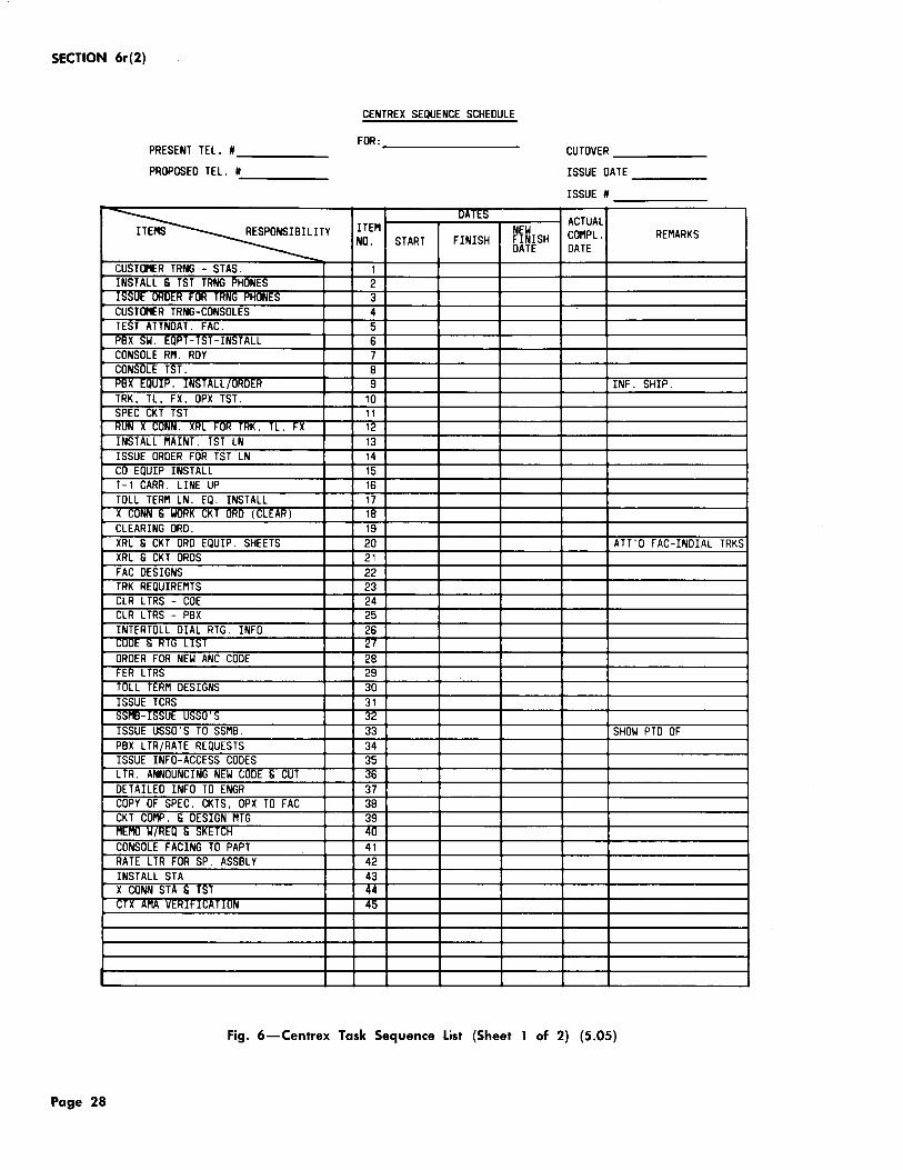
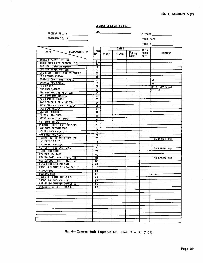
5.05 An additional item which aids in the development of a cutover schedule is the
centrex task sequence list. An example of a sequence list is shown in Figure 6. The list is not all-inclusive but is intended only as an example of such a list. The list contains task-oriented entries which are numbered and assigned to the various telephone company departments. The sequence list may be developed at the first meeting of the centrex committee but will usually be developed from some standard list. In any event, the centrex committee should establish dates for starting and completing each task and, if possible, this should be done during an early meeting. The sequence list may then be attached to or incorporated into the centrex memorandum.
5.06 As the centrex job progresses, the centrex committee may meet frequently to review
the job progress or to make schedule or service changes. (In some companies the committee may meet on a regularly scheduled basis at a time mutually agreed upon by members of the committee or prescribed by standard company procedures.)
5.07 During the planning and cutover period, the network administrator's primary responsibility
is to prepare the necessary office translations required to provide the centrex service to the customer based upon information obtained from the centrex committee memorandum and the marketing representative (or other customer services representative). The information required to complete the translation forms must be accurate, detailed, and well documented. A good method of ensuring this is to use a standard company questionnaire or checklist which covers all translation requirements.
5.08 One item which must be determined when planning for a centrex group is the size of
the block of numbers to be used by or reserved for the group. There should not be a tendancy to hold large blocks of numbers in reserve for growth in centrex groups. These numbers may never be used or paid for. The network administrator should be aware of the number of working numbers versus the number of reserved numbers. Marketing should be approached for the latest forecast information in order to make the most effective use of the available numbers.
6. CENTREX TRANSLA liONS
6.01 The No. 1 ESS utilizes stored data to control a configuration of data processing, input/output,
and switching equipment. This concept is referred to as stored program control. There are three distinct categories of data which make up the stored program; they are the generic, the parameters, and the translations.
6.02 The generic program is a group of instructions which direct normal telephone switching
operations of line and trunk interconnections and the maintenance routines for automatic detection of component and package failures. It is basically identical in all offices using that particular generic program.
6.03 The parameters contain concentrated reference information required by the generic program.
These data vary from office-to-office and provide a detailed description of the office including the features available, the hardware configuration, and the quantity and types of data storage areas referenced by the generic program.
6.04 The translations data consist of information which defines the characteristics of the
individual office and each customer within the office. Translations are unique for each No. 1 ESS office and it is here that the centrex customer is allowed or denied the many features and options available with centrex service.
6.05 The network administrator is responsible for ensuring that all of the necessary
translation forms are completed properly and within the scheduled time. Before starting the actual form preparation, the data should be reviewed to gain an exact picture of the service to be translated. While reviewing the data, it should be kept in
ISS 1, SECTION 6r(2)
mind that the data should fall into one of three general categories of translation data. These are office-type information, group information, and line information.
6.06 Office-type information includes those items which are needed for general call processing.
Examples of this type of information are line class codes, abbreviated classes, and routing and charging information. These types of information are needed to process POTS as well as centrex calls and form the groundwork for the office.
6.07 Group-type information includes data which are common to all or part of the centrex
group. Examples of this type of information are feature offerings, console data, dialing assignments, trunk requirements, etc. These types of information are needed to define the characteristics of the centrex group as a whole.
6.08 Line-type information includes data which pertain to the individual stations which make
up the centrex group. This is basically detailed number and feature information and is needed to associate the two.
6.09 The network administrator's primary source of information for preparing translations is
the No. 1 ESS translation guide (TG-1A). It is therefore important that this document be kept current and that pages are inserted or removed in accordance with the TG-1A transmittal notices which are distributed by Western Electric. Supplementing TG-1A are American Telephone and Telegraph Company letters, local company directives, and Feature Documents.
6.10 The sequence for completing input forms may not be the same for all offices and
usually will not be obvious. It is generally good practice to begin by translating the office-type data. This information will be required later and backtracking is likely to cause translation errors. Also, all of the group and line informaton is not needed to complete this work. After the office data, group data may be translated. Most group information is required on the Centrex Group Record-Form 1109. This task can be accomplished without detailed line information. Line translations are best left as the final translation task. Most centrex line information is required on the Directory Number Record-Form 1101. The information on the form will include each directory number, its
Page 7
SECTION 6r(2)
appearance on the network, and the line class code and feature information for each.
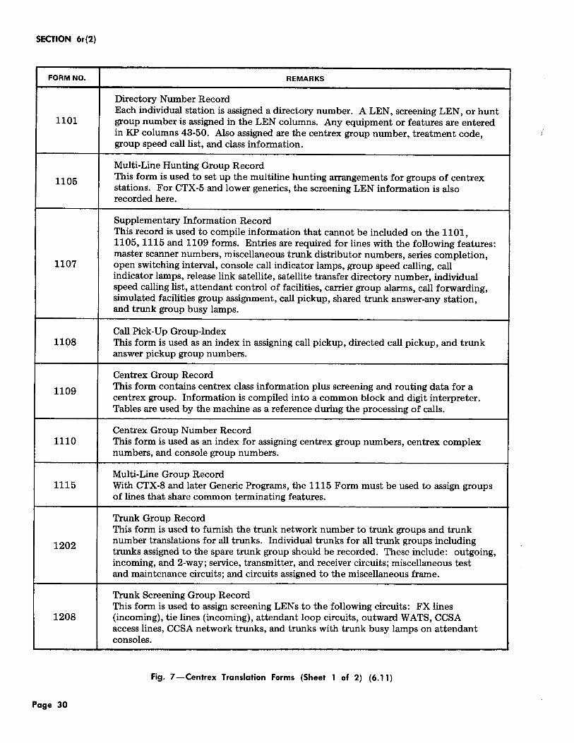
6.11 Most of the translation forms which require entries for centrex service are mentioned in
Figure 7. The responsibilities for completing these forms vary among different groups from area to area, but are presented as an overview of the general entries that may be required to provide centrex service. When completed, all forms relating to a centrex customer should be kept together, along with the customer's specification, with other translation forms to aid in verification, additions, and deletions. These forms serve as the office records.
6. 12 Instructions for preparing translation forms are provided in Division 3 of TG-1A. Also
provided is a subject index which indicates the translation forms which may apply for each centrex feature. The instructions must be read to determine if and in what manner a particular form applies. Division 6 of TG-1A contains reproducible copies of all the forms.
6.13 Completed translation forms for new offices must be submitted to Western Electric for
processing. There the information contained on the forms is processed by the translation data assembly (TDA) process and transformed into data tables which are compatible to the No. 1 ESS data processing system (central control). Translation information for offices already in service is added to or changed using the recent change process.
6.14 Some recent change information is effective as soon as the associated messages from
the teletypewriter (TTY) are entered into the system. This data is said to be recent change hunted. Information which is not recent change hunted will not be rendered effective in call processing until program store memory cards are rewritten. Whether an item is recent change hunted will depend upon the generic in use. Generally, changes to centrex common block or digit interpreter table information will require a card write while changes to line, speed calling list, flexible route selection, or simulated facilities information will be recent change hunted. For additional information concerning recent changes refer to Bell System Practice Section 231-118-321.
Page 8
7. TRAFFIC MEASUREMENTS
CENTREX TRAFFIC REGISTERS
7.01 Centrex measurements are provided as part of the hourly (H and C) schedules. These
measurements provide data for each type of centrex-CO call which can originate in a centrex-serving office. The measurements include peg counts, usage, and overflow. Any centrex group may be assigned to either the H-schedule, or the C-schedule. A complete listing and description of the No. 1 ESS traffic registers is provided in Division 3 of TG-1A. Dial Facilities Management Practices, Division H, Section 6i(2), Data Administration-Hourly, describes the methods used to schedule, collect, and print out traffic data associated with the Hor C-schedules.
RELATED TRAFFIC REGISTERS
7.02 Traffic registers which are applicable to some centrex customers are the trunk, service
circuit, simulated facilities group and multiline hunt group registers of the H- or C-schedule. The trunk registers may be used to measure usage, overflow, etc, on foreign exchange and tie trunks. The simulated facilities group registers may be used to measure like information for software simulated trunk groups such as wide area telephone service (WATS) and simulated PBX dial-9 trunks. The multiline hunt group registers may be used to obtain traffic measurements on inward wide area telephone service (INW ATS) trunk groups.
8. GROWTH
8.01 Once a No. 1 ESS office is in service, growth in centrex service can be accomplished
utilizing the recent change capabilities of the machine. This method serves the needs of the telephone companies as long as the number of growth customers is small. For large-scale growth, the usual time limits and other factors begin to overpower the staff normally responsible for recent change updates.
TRANSLATION GROWTH PROCESS
8.02 The translation growth process (TGP) is a Western Electric support program designed
to reduce telephone company effort for large-scale line growth in No. 1 ESS offices with centrex-5, Issue 6.2 or higher generic programs.
8.03 The large-scale line growth in the No. 1 ESS could be the result of an area transfer or a
new centrex customer. TGP provides the option of activating all lines simultaneously or by number group.
8.04 TGP is a subsystem associated with the translation data recovery and reprocessing
system service (TDRRSS). TGP merges the new line translation information with the existing translation data in an in-service office.
8.05 The economic break-even point of TGP versus the recent change procedure for activating
the new lines is at approximately 7000 lines. Below this number the recent change procedure is usually less costly. However, there may be instances where TGP might still be more convenient.
8.06 The TGP processing interval is normally 13 weeks. This is the interval from the receipt
of the ESS forms in the Western Electric regional center until the loading of the new program store cards into the office.
8.07 Because the first ten weeks of the interval are used for keypunching and error-checking
the input, the telephone company has the option of updating the growth input during the first eight weeks of this interval.
8.08 The existing TDA error-check system is used to perform the required data checks. The
same error-check message dictionary is used.
8.09 The required translation forms plus additional information pertaining to TGP are provided
in Division 1, Section 5 and Division 10, Section 7 of TG-1A.
ABBREVIATED CLASS CODES
8.10 An extremely critical area of memory administration is the abbreviation of centrex
lines, especially when centrex customers are added to an in-service machine. Variations in the services provided to individual centrex lines can cause large amounts of memory to be used unless proper care is taken to establish the abbreviated classes. Abbreviation of centrex originating classes is accomplished by using an entry in the abbreviated class code record {1502A) to point to a supplementary abbreviated class code record (1503 series). Additional information pertaining to centrex abbreviated class
ISS 1, SECTION 6r(2)
codes is provided in Dial Facilities Management Practices, Division H, Section 6h(2), Memory Administration, Translation Area.
9. PROBLEM ANALYSIS
PROBLEM DETERMINATION
9.01 Common centrex-related problems encountered by the network administrator are those
which result from translation errors or blockage. These problems are usually channeled to the network administrator by marketing personnel. Analysis of network problems requires skill which can only be developed through experience and through knowledge of the equipment and software used to serve the customer.
TRANSLATION PROBLEMS
9.02 Two types of translation problems which the network administrator may encounter
are those which are incompatible to the TDA System and those which result in improper service to the customer. Those translation errors which are incompatible to the TDA are reported back to the telephone company by Western Electric before the TDA run. The TDA computer run is preceded by an error-checking process known as the TDA error-check program. The purpose of the pre-TDA program is to identify errors before the beginning of the actual TDA run. Identifying the errors before the actual run permits many of the errors made in preparation of input forms to be corrected and reduces the requirement for multiple TDA runs.
9.03 Division 11 of TG-1A covers the different TDA input forms and the possible error
codes which can be generated. It must be noted that the TDA error check does not identify all possible input errors. It is the responsibility of the telephone company to provide accurate and complete input data to Western Electric.
9.04 Translation errors which are compatible to the TDA but which result in improper service
are more difficult to correct because the only clues to the trouble are the symptoms and even these may not be obvious. Experience and a working knowledge of the equipment and software are prerequisites for isolating the problem and effecting corrective action.
Page 9
SECTION 6r{2)
BLOCKAGE
9.05 Blockage can result from a translation problem which causes the machine to handle
customer traffic ineffectively but the cause is more likely to be a lack of sufficient hardware available to handle the volume of calls during the customer's busy hour. For example, a customer's WATS service is limited by a SFG and although there may be substantial physical hardware available, the software limits the number of circuits which can handle the customer's traffic; overflow results if the SFG is too small.
PROBLEM ANALYSIS AND CORRECTIVE ACTION
9.06 Network administrators must use their experience and system knowledge along with
the office records and applicable traffic registers in order to isolate a particular problem. If the problem is not obvious, it will help to postulate a set of circumstances which could cause the problem and then determine if that set of circumstances exists for the actual problem. This may merely require checking office records and service orders to determine if a customer is being provided the service due. Appropriate traffic registers should be checked when blockage occurs to determine if the customer's volume of traffic falls within the range of the facilities available to handle that traffic. A check of the traffic registers may reveal that the facilities purchased by the customer are insufficient to handle the traffic load, that a translation error is causing reduced service, or that the customer's busy hour has shifted and is causing service degradation in the central office.
9.07 Once the cause of a problem has been isolated, corrective action should be taken.
Implementing corrective action may be a matter of inserting a recent change into the office translations or it may require adding to or rearranging the existing equipment to accommodate the customer.
1 0. SPECIAL REQUIREMENTS
DIVISION OF REVENUE
10.01 Division of Revenue studies are made and used to determine the amount of revenue
each company will receive for the use of their facilities.
Page 10
1 0.02 The Division of Revenue function is performed in the following manner. Routinely, each
network administrator collects Division of Revenue peg counts on a sample basis. These data are manipulated and scaled up to total-month peg counts and summed over all switching machines in the entire Division of Revenue area. Each month the data are inputted to a Long Lines computer program which computes each company's share of the Bell System's total interstate toll revenue for that month. In addition to the computations for the Bell System intercompany revenue division, monthly settlements are made between the Bell System company and all non-Bell System companies with which the Bell System company interfaces.
10.03 Division of Revenue traffic data must be collected and manipulated to separate
revenue-sharing data from nonrevenue-sharing data. The data are collected for the following categories:
• Originating traffic
• Intercentrex traffic
• CCSA traffic
• Toll traffic on selected trunk groups
• Direct distance dialing message network traffic.
The methods and registers used for data collection vary from company to company but are usually specified by a Division of Revenue group. The data collected by the network administrator are forwarded to that group for processing.
LINE ASSIGNMENT
10.04 In addition to the general guidelines for line assignment given in Dial Facilities
Management Practices, Division H, Section 6g, Load Balancing Procedure, care should be taken to spread centrex lines evenly across the concentrators, switches, and quarter switches both by customer group and class of service. This being done, a usage study should be made shortly after cutover to determine if load is evenly distributed. This is important in as much as centrex groups may tend to add a relatively large amount of usage to the machine suddenly as compared to noncentrex customers.
NUMBER ASSIGNMENT
10.05 The No. 1 ESS does not require centrex numbers to be consecutive in nature. Nor
are there any other restrictions which are placed on centrex numbers by the machine itself. However, administratively it is desireable to have consecutive blocks of numbers for centrex groups. Consecutive numbering plans are easier to administer and record, are less likely to cause errror ·or misinterpretation between the customer and the telephone company, and are more efficient where program store space is concerned.
10.06 A centrex system may have 2-, 3-, 4-, 5-, 6-, or 7-digit intragroup station dialing
independent of other centrex intragroup patterns. Each centrex station equipped for DID is assigned a 7-digit number. The number is used to complete incoming calls originating outside the customer group (DID calls) and to identify the station for AMA entries associated with toll calls originated by that station. The last two, three, four, five, six, or seven digits of the DID number correspond to the intragroup station number. Access codes must be used for calls to central office numbers, attendants, trunks, and special services. For this reason, it is recommended that the initial digit of the centrex stations begin with 2, 3, 4, 5, 6, or 7.
• "0" is normally used to access the attendant.
• "1" is normally used to access special services, ie, tie lines.
• "8" is normally used to access the CCSA.
• "9" is normally used to access outgoing trunks.
10.07 An NXX code composed of 10,000 7-digit central office numbers could be assigned
as follows:
NNX-OXXX POTS
NNX-1XXX POTS
NNX-2XXX Centrex or POTS
NNX-3XXX Centrex or POTS
NNX-4XXX Centrex or POTS
ISS 1, SECTION 6r(2)
NNX-5XXX Centrex or POTS
NNX-6XXX Centrex or POTS
NNX-7XXX Centrex or POTS
NNX-8XXX POTS.
10.08 Although the centrex customer may not want CCSA, special services, etc, initially,
it is recommended that allowances be made for such contingencies when developing the centrex dialing plan.
10.09 The digit timing feature in CTX-7 and later generic programs provides the ability to
use conflicting variable length codes in centrex-CO dialing plans. For example, access code 180 and station number 1800 may be assigned as valid dialing patterns in the same centrex group. For dial pulse stations, end of dialing timing is used to distinguish between the dialing of 180 and 1800. For TOUCH-TONE stations, the "#" should be used to indicate the end of dialing. This cancels end of dialing timing and allows the immediate processing of the dialed digits.
INTERCEPT ARRANGEMENTS
10.10 Centrex customers utilize the same general intertoll and switching blockage intercept
arrangements as POTS customers. However, because of the high usage rate of business customers and the variety of features available to centrex customers, additional intercept arrangements may be provided which meet an individual centrex customer's unique needs. These include intercept arrangements for:
• Access code dialed in error
• Access code not dialed
• Nonworking centrex station
• Common centrex announcement (intracentrex calls-RI0150)
• PBX service converted to centrex
• Customer calling.
These intercepts are further broken down in Figure 8. The equipment required to provide the intercept may be located at the central office or
Page 11
SECTION 6r{2)
on the customer's premises, depending upon the type of intercept and the type of centrex service provided.
10.11 The network administrator is responsible for generating the translations necessary
to provide the intercepts for a centrex customer. When and how a call is intercepted are determined by entries in the office translations. Most centrex intercepts are provided as a matter of common practice when the network administrator prepares the translations for the centrex group.
10.12 Special cases may arise wherein the customer requires some unique intercept arrangement
or a variation of one of the more common arrangements or the customer may wish to control the intercept using equipment located on the customer's premises. These special cases should be brought to the attention of the network administrator by marketing personnel or during a meeting of the centrex cutover committee in order that the network administrator may generate, if necessary, the required translations.
l 0.13 Intercept arrangements and recorded announcements are discussed further in Dial
Facilities Management Practices, Division H, Section 6d(5), Recorded Announcements, and Division H, Section 1b(13), Tones and Announcements.
BUSINESS SERVICES/MARKETING REQUIREMENTS
10.14 The business services representative is responsible for familarizing the customer
with the centrex equipment and features and for training the customer and the customer's employees in its proper use. Some telephone companies provide special training centers for this purpose. Training may also be provided for a limited period of time on the customer's premises.
10.15 If temporary training facilities are to be provided on the customer's premises, the
network administrator is responsible for generating the necessary translations and assigning the
Page 12
appropriate terminals required to serve the training facilities.
10.16 Business services may occasionally require network measurements in order to satisfy
a request by a centrex customer. The network administrator is in the best position to decide which measurements are required and available to provide them to the requesting department.
11. REFERENCES
11.01 The following is a list of references which contain information pertaining to this section.
(a) Dial Facilities Management Practices:
(1) Division H, Section 6d(5), Operational Features, Recorded Announcements, No. 1
Electronic Switching System
(2) Division H, Section 6h(l), Memory Administration -Organization
(3) Division H, Section 6h(2), Memory Administration-Transiation Area
(4) Division H, Section 6i(l), Data Administration-Hourly
(b) Translation Guide:
Translation Guide, TG-1A, No. 1 Electronic Switching System.
(c) Bell System Practice:
Section 231-118-321, General Recent Change Information
Section 966-102-100, Centrex and PBX-CO Service, General Description
(d) Traffic Facilities Practice:
Division D, Section 10j, Centrex

MIS OR OTHER EQUIPMENT
ATTENDANT CONSOLE
CENTREX STATIONS
CUSTOMER PREMISES
CENTREX CUSTOMER GROUP
REMOTE DATA INTERFACE
CENTREX CONSOLE CONTROL CABINET
DATA LODF
DATA LOOP
CENTREX DATA Ll NK
ISS 1, SECTION 6r(2}
NO. I OR NO. lA ESS CENTRAL PROCESSOR
i.·,,.-·,._,:,·r,:·,'.':;·~·'•;-:',!:: .. ,.~ .. :~,·,:,',,· .. :'_·.:· ... '·:: "·· .. ,... 1 L------ii~-T~:~~~~~K~E~~~~~:~~~~~IT~-ffi~i~~: ____________________ r-----------t---------------,
(TALKING PATH)
SUBSCRIBER LI.NES
INTERCONNECTING LINES
NON-CENTREX SUBSCRIBER
LINE LINK
NETWORK
TRUNK LINK
NETWORK
ESS SWITCHING FRAMES
2-WIRE NO. I ESS CENTRAL OFFICE
ATND TRUNK
ANO LOOP
CIRCUITS
TIE TRUNKS AND FOREIGN EXCHANGE TRUNKS TO OTHER SWITCHING SYSTEMS
Fig. 1-Centrex Simulated PBX System With Centrex Data Link Hardware (3.09, 3.23)
Page 13
SECTION 6r(2)
121•, 131·. OR ISI•TYPE ATTENDANT CONSOLE
NOTE:
• • •
FOR PBX•CO, NO DID TO STlTIOMS IS PERM I TT£0. FOR C[IITREX•CO SEitYICE, DID IS AllOWED.
CENTREX-CO CUSTOMtR GROUP OR
PBX•CO CUSTOMER GROUP
I i!:!:i .
~~~ &
~
I 1@ ~X~ ~
~~ q;
~~ *" ~~ > ·:~
I ~ ~: t.4 ·t
: i:(:i
li I I ·. ·~ .. '
j. .
:.i
·~~
'I t .:;: b~
I . . ?
I I
I <
.
ATTENDANT LINES
SU8SCRIB£R LINES
(SEE NOTE)
UITERCONNECT IIIG llltf;S
I . z ~,
I '*'-"' ~~ &'J.
.. ::· ~] ~f ~>: ~.J. ti:;: ~~ ~N -I ;::.:$;: :;.~
%~
I ~ ~» ~! ~ ~.~ :=&h;: ;,~· &~ ;m: \~i
I til r::::~
*' ii' i:(:i
it,,~
I *m II !$ !i~ 11 ¥:J :~
~ ~ ?$ $<: ti1 ::::·~
~ k~ I ~>~
'~* ~'l'i 00
•
LINE LINK NETWORK
TRIJHK LINK NETWORK
ESS SWITCHING FRAMES
]
TIE TRIJHKS AND FX TRUNKS
2-WIRE NO. I OR NO. lA ESS CENTRAL OFFICE
Fig. 2-CentreJC or Simulated PBX SYJtem Without Centrex Data Link Hardware (3.17, 3.27)
Page 14
(
STATIONS
STATION LINES
SWITCHING EQUIPMENT
Alii EQUIPMENT
CENTREX CUSTOMER GROUP
• • •
DIRECT OUTDIAL TRUNKS
DIRECT INDIAL TRUNKS
INK
INTERCONNECT lNG LIMES
• • •
ISS 1, SECTION 6r(2)
LINE LINK NETWORK
TRUNK LINK NETWORK
ESS SWITCHING FRAMES
AIOD INTERFACE CIRCUIT
2-WIRE NO.I OR NO. lA ESS CENTRAL OFFICE
Fig. 3-Centrex System (AIOD Configuration) (3.19)
Page 15
SECTION 6r(2)
Page 16
PBX CENTREX
Series 100 Centrex I
Attendant Position {Console) Attendant Position {Console) Call Transfer - Attendant Call Transfer - Attendant Direct Outward Dialing Direct Inward Dialing Night Service Direct Outward Dialing Power Failure Transfer - Station Identified Outward Dialing Restriction From Outgoing Calls Night Service Station Hunting Reserve Power Station-To-Station Calling Miscellaneous Trunk Restriction
Station Hunting Series 200 Station-To-Station Calling
Series 100 Features Plus Centrex II Attendant Camp-On Attendant Conference Centrex I Features Plus Attendant DSS W/Busy Lamp Field Consultation Hold Indication of Camp-On Add-On {3-Way Calling)
Call Transfer - Individual Series 300 Trunk Answer From Any Station * *
Series 200 Features Plus Consultation Hold Add-On (3-Way Calling) Call Transfer-Individual Trunk Answer From Any Station *
* Less the Night Service feature, requirement fulfilled by Night Position option where available.
** Fulfills Night Service requirement.
Fig. 4-Centrex and PBX Feature Packages (4.02)
ISS 1, SECTION 6r(2)
These forms may be used by the centrex cutover committee as a guide to provide translation data and develop implementation schedules.
Date Issue No. Prepared By Tel. No.
1. GENERAL INFORMATION
1.01 Responsibility N.A. Network Administration I. & R. = Plant Installation & Repair M Marketing P.E. PBX Engineering B Business Office c.c. Cutover Committee N.D. Network Design Engineering L.L. Long Lines N.M. Network Maintenance S.S.B. Special Service Bureau P.A.O. = Plant Assignment Office B.S. Business Services
1.02 Customer name (M) 1.03 Customer address (M) 1.04 Requested service date (M) 1.05 Serving ESS office (N.D.) 1.06 Central office code (NA) 1.07 Centrex service (M) 1.08 Type consoles (BS) 1.09 Quantity of consoles (BS) 1.10 Loops per console (1 thru 6) (BS) 1.11 Touch Tone (percent of stations) (M) 1.12 Class "A" essential (quantity of lines) (M) 1.13 Centrex complex arrangement (M)
Yes No (M)
Fig. 5-No. 1 ESS Centrex Translation and Cutover Data (Sheet 1 of 11) (5.04)
Page 17
SECTION 6r(2)
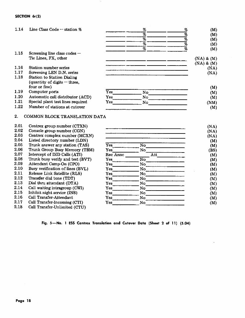
1.14 Line Class Code - station % % % (M) % % (M) % % (M) % % (M) % % (M)
1.15 Screening line class codes -Tie Lines, FX, other (NA) & (M)
(NA) & (M) 1.16 Station number series (NA) 1.17 Screening LEN D.N. series (NA) 1.18 Station to Station Dialing
(quantity of digits- three, four or five) (M)
1.19 Computer ports Yes No (M) 1.20 Automatic call distributor (ACD) Yes No (M) 1.21 Special plant test lines required Yes No (NM) 1.22 Number of stations at cutover (M)
2. COMMON BLOCK TRANSLATION DATA
2.01 Centrex group number (CTXN) (NA) 2.02 Console group number (CGN) (NA) 2.03 Centrex complex number (MCXN) (NA) 2.04 Listed directory number (LDN) (M) 2.05 Trunk answer any station (TAS) Yes No (M) 2.06 Trunk Group Busy Memory (TBM) Yes No (BS) 2.07 Intercept of DID Calls (ATI) Rec Anne Att (M) 2.08 Trunk busy verify and test (BVT) Yes No (M) 2.09 Attendant Camp-On (CPO) Yes No (M) 2.10 Busy verification of lines (BVL) Yes No (M) 2.11 Release Link Satellite (RLS) Yes No (M) 2.12 Transfer dial tone (TDT) Yes No (M) 2.13 Dial thru attendant (DTA) Yes No (M) 2.14 Call waiting intragroup (CWI) Yes No (M) 2.15 Inhibit night service (INS) Yes No (M) 2.16 Call Transfer-Attendant Yes No (M) 2.17 Call Transfer-Incoming (CTI) Yes No (M) 2.18 Call Transfer-Unlimited (CTU)
Fig. 5-No. 1 ESS Centrex Translation and Cutover Data (Sheet 2 of 11) (5.04)
Page 18
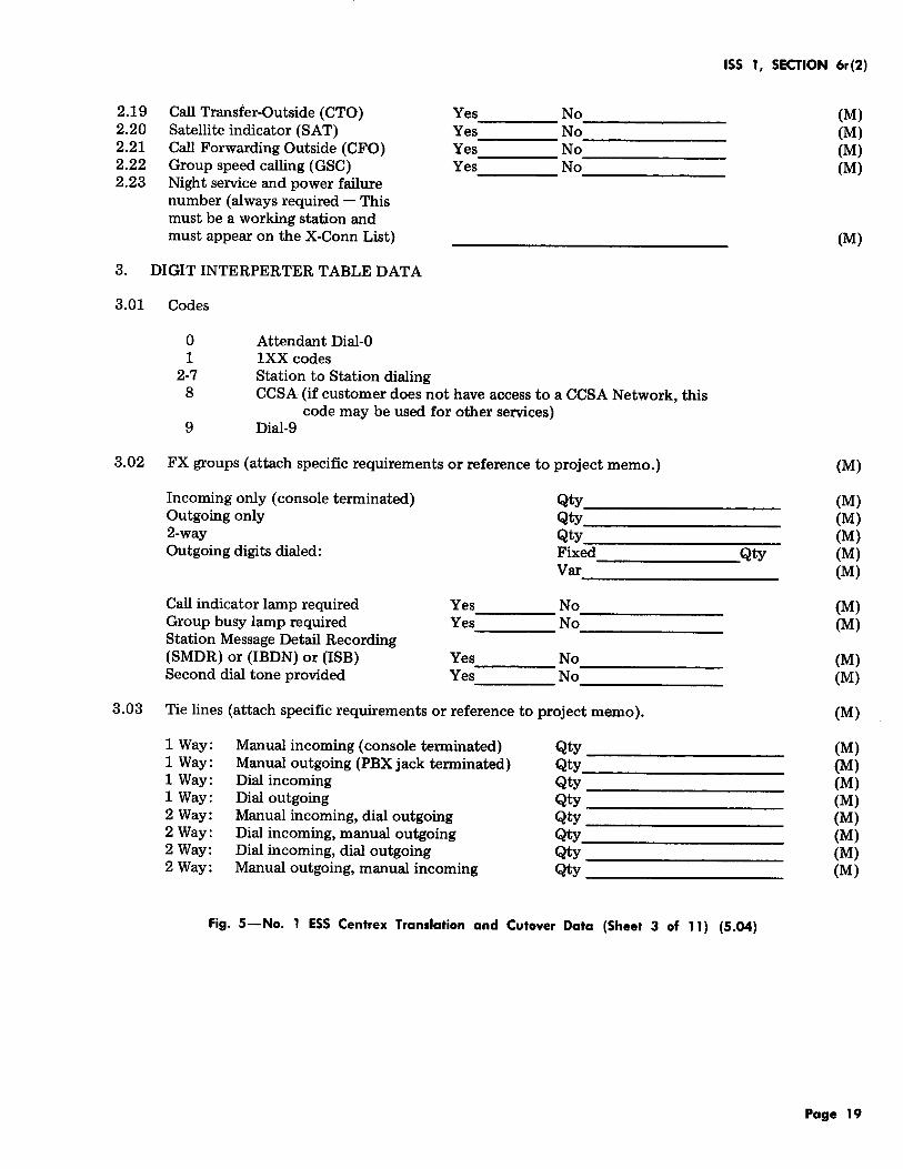
2.19 2.20 2.21 2.22 2.23
3.
3.01
3.02
3.03
Call Transfer-Outside (CTO) Yes No Satellite indicator (SAT) Yes No Call Forwarding Outside (CFO) Yes No Group speed calling (GSC) Yes No Night service and power failure number (always required- This must be a working station and must appear on the X-Conn List)
DIGIT INTERPERTER TABLE DATA
Codes
0 Attendant Dial-0 1 1XX codes
2-7 Station to Station dialing 8 CCSA (if customer does not have access to a CCSA Network, this
code may be used for other services) 9 Dial-9
FX groups (attach specific requirements or reference to project memo.)
Incoming only (console terminated) Qty Outgoing only Qty 2-way Qty Outgoing digits dialed: Fixed
Var
Call indicator lamp required Yes No Group busy lamp required Yes No Station Message Detail Recording (SMDR) or (IBDN) or (ISB) Yes No Second dial tone provided Yes No
Tie lines (attach specific requirements or reference to project memo).
1 Way: Manual incoming (console terminated) Qty 1 Way: Manual outgoing (PBX jack terminated) Qty 1 Way: Dial incoming Qty 1 Way: Dial outgoing Qty 2Way: Manual incoming, dial outgoing Qty 2Way: Dial incoming, manual outgoing Qty 2Way: Dial incoming, dial outgoing Qty 2Way: Manual outgoing, manual incoming Qty
ISS 1, SECTION 6r (2)
Qty
(M) (M) (M) (M)
(M)
(M)
(M) (M) (M) (M) (M)
(M) (M)
(M) (M)
(M)
(M) (M) (M) (M) (M) (M) (M) (M)
Fig. 5-No. 1 ESS Centrex Translation and Cutover Data (Sheet 3 of 11) (5.04)
Page 19
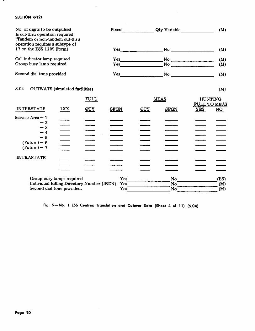
SECTION 6r(2)
No. of digits to be outpulsed Is cut-thru operation required (Tandem or non-tandem cut-thru operation requires a subtype of 17 on the ESS 1109 Form)
Call indicator lamp required Group busy lamp required
Second dial tone provided
3.04 OUTWATS (simulated facilities)
Fixed ______ Qty Variable _____ _
Yes No ------------- ---------------Yes No Yes-------------- No--------------
Yes ______________ No--------------
(M)
(M)
(M) (M)
(M)
(M)
HUNTING FULLTOMEAS YES NO -- --
Group busy lamps required Yes ______________ No _______ (BS) Individual Billing Directory Number (IBDN) Yes No (M) Second dial tone provided. Yes No (M)
Fig. 5-No. 1 ESS Centrex Translation and Cutover Data (Sheet 4 of 11) (5.04)
Page 20
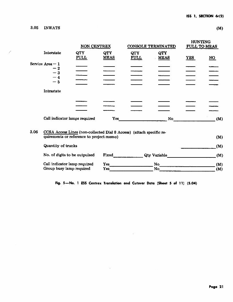
3.05 INWATS
Interstate
Service Area- 1 -2 -3 -4 -5
Intrastate
NON CENTREX
QTY QTY FULL MEAS
CONSOLE TERMINATED
QTY QTY FULL MEAS
ISS 1, SECTION 6r(2)
(M)
HUNTING FULLTOMEAS
Call indicator lamps required Yes _________ No ________ (M)
3.06 CCSA Access Lines (non-collected DialS Access) (attach specific requirements or reference to project memo) (M)
Quantity of trunks
No. of digits to be outpulsed
Call indicator lamp required Group busy lamp required
______ (M)
Fixed ______ Qty Variable _________ (M)
Yes. ________ No ___________ (M) Yes No (M)
Fig. 5-No. 1 ESS Centrex Translation and Cutover Data (Sheet 5 of 11} (5.04)
Page 21

SECTION 6r(2)
3.07 Centrex treatment codes (M)
Treatment Code
No Access
Facility l:XX 0 1 2 3 4 5 6 7
v v v v v v v v I
v ' v
v v Allow Access
3.08 Features - lXX access
lXX Assign (M/BS)
A. Group speed calling (30 code) Yes No (M) B. Individual speed calling ( 6 code) Yes No (M) c. Call hold Yes No (M) D. Call pick up Qty ofGrps Yes No (M) E. Code calling
Originate Yes No (M) Answer Yes No (M)
F. Trunk answer any station Yes No (M) G. Paging Radio __ Voice __ Qty __ Yes No (M) H. Dial dictation - Qty Yes No (M) I. Attendant conference 6-port Qty __ Yes No (M) J. Station conference 6-port Qty Yes No (M) K. Call forwarding variable activate Yes No (M) L. Call forwarding variable deactivate Yes No (M) M. Flexible Route Selection Yes No (M)
Fig. 5-No. 1 ESS Centrex Translation and Cutover Data (Sheet 6 of 11) (5.04)
Page 22
3.09 Other features
A. Attendant control of facilities B. M.L.H. circle hunt c. M.L.H. preferential hunt D. M.L.H. uniform call distribution E. Call forwarding - busy line F. Call forwarding- don't answer G. Call Waiting- Originating H. Call Waiting- Terminating I. J.
3.10 Other comments and notes
Enter names of responsible persons:
4.01 4.02 4.03 4.04 4.05 4.06 4.07 4.08 4.09 4.10 4.11 4.12 4.13 4.14 4.15 4.16 4.17
4.18
USOC codes Call indicator lamps Group busy lamps Special service orders Special service orders Traffic Register Assignments Abbreviated line class code Routing and charging transl. Trunk Translations Trunk orders ESS 1109 for:r;n Data link assignments Console test dates From CTX station test dates From Console cabinet to C.O. Console cabinet to plant Station X-conn list {manual) a. (S) to (P.A.O.)
(CA. PR. assign) b. (P.A.O.) to (N.A.)
(LEN assign) c. (N.A.) to {P.A.O.)
(R.C. tapes & distribution) Other ---------------------
ISS 1, SECTION 6r(2)
Yes No (M) Yes No (M) Yes No (M) Yes No (M) Yes No (M) Yes No (M) Yes No (M) Yes No (M)
Provided Provided By To Date Completed
(M) (NA) (BS) {NA) (BS) (NA) (M) (SSB) (SSB) (NA) (NA) (NM) (NA) (NM) (NA) (NM) (NA) (NM) (NA) (NM) (NA) (NM) (NA) (NM) To To (PE) (CO) (CO) (IER)
Fig. 5-No. 1 ESS Centrex Translation and Cutover Data (Sheet 7 of 11) (5.04)
Page 23
"3 U2
CD ..., ..
LAMP DESIGNATION BY LAMP NUMBER
OUTGOING INCOMING
GRP. BSY. GRP. BSY. CALL IND. CALL IND.
05 11 11 5 ATT'D "0'' 04 10 10 4
03 09 9 3
02 08 8 2
01 07 7 1
00 06 6 0 LISTED NUMBER ..
BZ C) C)~;, ON
TRK. GRP. CALL BUSY INDICATOR LOOPS
I \ I \ I KEY SRC DES\ cw ROY FA
~ G G QJ [8J D D [8J 0 0 0 [8J [8J POS. BY NITE
~ ~ ~ G [8J D D [8J CJ QJ QJ [±] L8J BSY. VER. SIG. DES.
~ ~ ~ QJ L8J D D [8J QJ QJ ~ [±] [8J SIG. SRC
~ ~ [!] Q] [8J D D [±] CJ QJ ~ [±] [8J RLS. DES. RLS. SRC CONF. 1
~ ~ [2] [2] [8J D D [±] D ~ 0 [8J [8J HOLD EXCL. DEST. CONF
~ ~ QJ ~ ~ D D [8J D [8J L8J 2
RLS ST EXCL. SRC.
NON-LOCKING I+ I [8J ILLUMINATED KEY NON-LOCKING KEY 1 B CONSOLE
Fig. 5-No. 1 ESS Centrex Translation and Cutover Data (Sheet 8 of 11) (5.04)
~ 5 z 2" B
: CD Ill ..., Ul
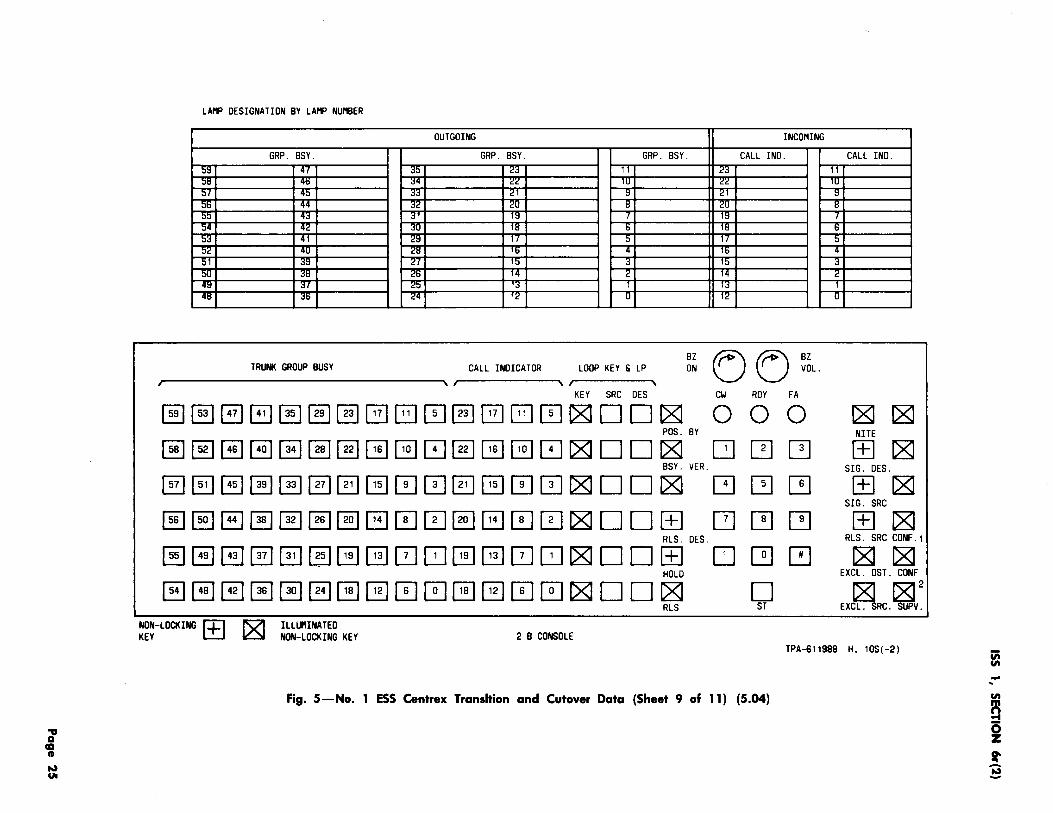
LAMP DESIGNATION BY LAMP NUMBER
OUTGOING INCOMING
GRP. BSY. GRP. BSY. GRP. BSY. CALL IND. :;,::~ 41 J:l 23 11 <'J :ltl 4ti ;:!4 "'"' lU "'"' ) ' 4: ;jJ <'1 l:l <'1
4' J<' <'U l:l <'I 4; J 1::1 I 1:
1 1 1 1 1 11 1 1:
:;,u Jtl <'ti 14 2 14 4l:l ;$/ <':l I;$ 1 1;:! 41:1 Jti <'4 1<' u 1<'
TRUNK GROUP BUSY LOOP KEY & LP ~~ C) C) ~~L. CALL INDICATOR
' , ' KEY SRC DES CW ROY FA
~~~B0~~0G0~0G0~DD~ 000 GQJQJ
PDS. BY
~~~~G~~~~~~~~~~DD~ BSY. VER.
~~~~~@JrE1~00El@J00~DDC81 G ~ QJ
~~EJ0C§J@J@JG00§1~00~0Dl±J CJ QJ QJ RLS. DES.
~12J~@l~@JG~0~GC!l0~~00[±] D ~ 0 HOLD
~~~~~~~~00~~00~00~ 0 RLS ST
NON-LOCKING I+ I """ ILLlJ'IINATED KEY ~ NON-LOCKING KEY 2 B CONSOLE
CALL IND. 11 1U
l:l
l:l
' t :
"' 1 u
1:811:81 NITE
[±]~ SIG. DES.
[±]1:81 SIG. SRC
[±] ~ RLS. SRC CDNF.1
~~ EXCL. DST. CONF
~ ~2 EXCL. SRC. SUPV.
TPA-611988 H. 10S(-2)
Fig. 5-No. 1 ESS Centrex Transition and Cutover Data (Sheet 9 of 11) (5.04)
2i
~ i sr 3
'l ca CD ...., 0.
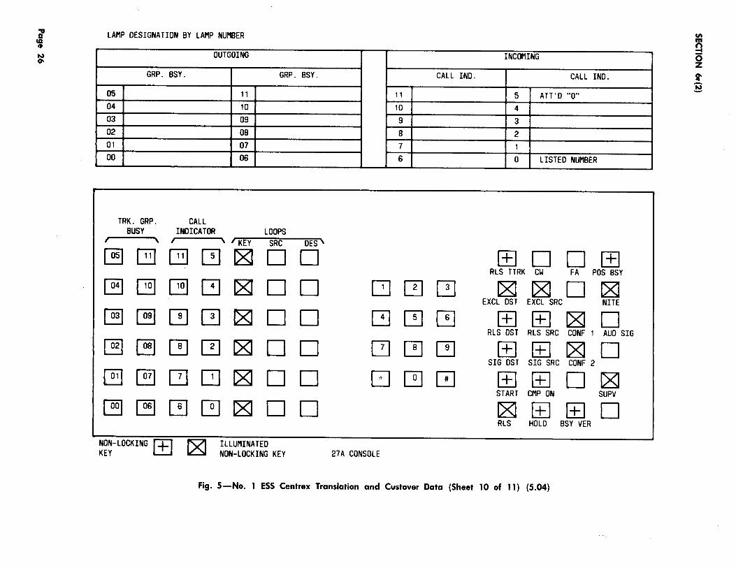
LAMP DESIGNATION BY LAMP NUMBER
OUTGOING INCOMING
GRP. BSY. GRP. BSY. CALL IND. CALL IND.
05 11 11 5 ATT'O "0" 04 10 10 4 03 09 9 3 02 08 8 2 01 07 7 1 00 06 6 0 LISTED NUMBER
TRK. GRP. CALL BUSY INDICATOR LOOPS
I ' I \ I KEY SRC DES\
~ G B QJ (Z] D D [±] D D [±] RLS TTRK CW FA POS BSY
~ ~ ~ QJ (Z] D D G QJ QJ ~ ~ D ~ EXCL DST EXCL SRC NilE
~ ~ QJ QJ (Z] D D G QJ ~ [±] [±] (Z] D RLS DST RLS SRC CONF 1 AUO SIG
~ ~ [!] QJ (Z] D D QJ [!] Q] [±] [±] L81 D SIG DST SIG SRC CONF 2
~ ~ [2] G (Z] D D [:J ~ 0 [±] [±] D L81 START CMP ON SUPV
~ ~ ~ ~ ~ D D C8j [±] [±] D RLS HOLD BSY VER
NON-LOCKING 1-+-1 lZJ ILLUMINATED KEY NON-LOCKING KEY 27A CONSOLE
Fig. 5-No. 1 ESS Centrex Translation and Custover Data (Sheet 10 of 11) (5.04)
Vt
0 0 z Sf' :§
'l 'I ~ ......
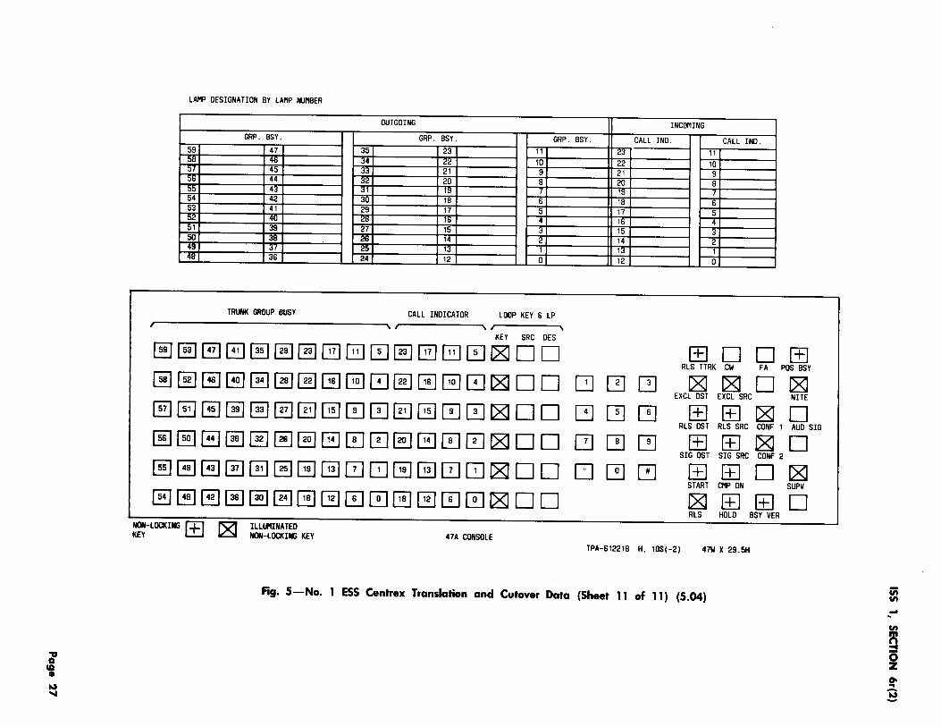
LAP'IP DESIGNATION BY LAI'IP NUI'IBER
OUTGOING
GRP. BSY. GRP. BSY. GRP. BSY. 59 47 35 23 11 58 46 4 22 10 :J 45 21 9 56 44 2 20 8 55 43 ll:l I 54 42 30 18 6 53 41 29 17 5 :Ji:: 4U i::I:J lti 4 51 39 27 15 3 50 38 26 14 2 4l:l 3 i::tl 1;:1 1 48 36 24 12 0
TRUNK GROUP BUSY CALL INDICA TOR LOOP KEY & LP ··-·······- ---~ ,.------.. ,-----,.
KEY SRC DES
~~~G~~~~G0~0G0~DD ~~~~~~~~~0~~~0~00
~~~~~~~~000~00~00 ~~8~~~~000~000~00 ~~~~~~G~0DG~0D~OO ~~~~~~~~00~~00~00
NOfHOCKING I+ I 1"::71 ILlli'IINATEO KEY ~ NON-LOCKING KEY 47A CONSOLE
Q]
QJ
QJ
LJ
INCOI'IING
CALL IND. CALL IND. 23 11 22 10 21 9 20 B ll;l ,_ 18 6 17 5 1J:i 4 15 3 14 2 I::S 1 12 0
[±] D D [±] RLS TTRK CW FA POS BSY
QJ QJ ~ ~ D ~ EXCL OST EXCL SRC NilE
QJ ~ 1±1 [±] ~ 0 RLS OS T RLS SRC CONF 1 AUO SIG
QJ QJ 1±1 [±] ~ 0 SIG DST SIG SRC CONF 2
~ QJ [±] [±] 0 ~ START CI'IP ON SUPV
~ [±] [±] D RLS HOLD BSY VER
TPA-612218 H, 105(-2) 47W X 29.5H
Fig. 5-No. 1 ESS Centrex Translation and Cutover Data (Sheet 11 of 11) (5.04) ;;; Cl)
; !' B
SECTION 6r(2)
PRESENT TEL. If _____ _
PROPOSED TEL. If;..._ ____ _
~TY CUSTOP'lER TRNG - STAS. INSTALL & TST TRNG PHONES ISSUE OOOER FOR TRNG PHONES CUSTOP'lER TRNG-CONSOLES TEST ATTNDAT. FAC. PBX SW. EQPT TST INSTALL CONSOLE RP'l. ROY CONSOLE TST. PBX EQUIP. INSTAll/ORDER TRK. TL. FX, OPX TST. SPEC CKT TST RUN X GUNN. XRL FOR TRK. Tl. FX INSTALL P'lAINT. TST LN ISSUE ORDER FOR TST LN CO EQUIP INSTALL T-1 CARR. LINE UP TOLL TERP'l LN. EQ. INSTALL X GUNN 1i WORK GKT ORO (GLEAR) CLEARING ORO. XRL & CKT ORO EQUIP. SHEETS XRL & CKT ORDS FAC DESIGNS TRK REQUIREMTS CLR LTRS - COE CLR LTRS - PBX INTERTOLL DIAL RTG. INFO GUOt li RTG LIST ORDER FOR NEW ANC CODE FER LTRS TOLL TERM DESIGNS ISSUE TCRS Sl:ii'IB··lS:>Ut USSU' 5 ISSUE USSO'S TO SSMB. PBX LTR/RATE REQUESTS ISSUE INFO-ACCESS CODES LTR. ANNOUNCING NEW CODE & CUT DETAILED INFO TO ENGR COPY OF SPEC. CKTS, OPX TO FAC CKT COMP. & DESIGN MTG MEMO W{REQ & SKETCH CONSOLE FACING TO PAPT RATE LTR FOR SP. ASSBLY INSTALL STA X CONN sTA & TST CTX AMA V lUN
CENTREX SEQUENCE SCHEDULE
FOO: _______ __
U!\ltS ITEP'l NEW NO. START FINISH FINISH
DATE
1 2 3 4 5 6 7 B 9
10 11 12 13 14 15 16 17 18 19 20 21 22 23 24 25 26 27 28 29 30 31 32 33 34 35 36 37 38 39 40 41 42 43 44 45
CUTOVER-----
ISSUE DATE ----
ISSUE If
ACTUAL COP'lPL. REMARKS DATE
INF. SHIP.
ATT"O FAC-INOIAL TRKS
SHOW PTD OF
Fig. 6-Centrex Task Sequence List (Sheet 1 of 2) (5.05)
Page 28
PRESENT TEL. II _____ _
PROPOSED TEL. 11'------
~" INSTAll MAINT. TST LN IssUE ORDER FOR OFFICIAL TEL. PUT STA. INFO IN MEMORY l:UI :SIA IAt't:S 1-!JH t:S:S OFC & GRP. INFO. PUT IN MEMORY OFC RECORD ASSIGN INSTAll OSP - SUB - CABLE INSTALL HSE CABLE PBX RM ROY OSP CABLE/ORDER TRK OSP FAC INSTALLATION t'BX sum SHT Dl:SIRIB PBX Sum SVC CTR-CA & PR - ASSIGN DATA TERM CA & PR - ASSIGN STA LINE ASSIGN CTX GRP ASSIGN INITIAL STA INFO DETAILED TEL SET INFO KEY SHTS TO I&R PROVIDE FLOOR PLNS FOR STAS ANC CODE PROCUREMENT ACCESS CODES FOR CTX OPEN NEW ANC CODE INSTALL & TST INTERCEPT EQP INTERCEPT EQUIP INTERCEPT ARRANGE l:UI U~~ - l:U:SIUI'ltH CHGS ISSUE CHG SHTS REVISED STA INFO REVIEW CUST. DIR. -DIAL INST REVIEW CUST. OIR. -DIAl INST ESTABLISH BILLING DATE PREP. & SUBMIT BILLii~G ORO TO ACCOUNTING BILLING ORDER INVENTOR & BILLING CHECK ISSUE SVC ORD-ADV LIST ESTABLISH CUTOVER COMMITTEE DETAILED CUTOVER PROCED.
CENTREX SEQUENCE SCHEDULE
FOR: _______ _
OATES ITEM NEW NO. START FINISH ~INISH ATE
51 52 53 54 55 56 57 58 59 60 61 62 63 64 65 66 67 68 69 70 71 72 73 74 75 76 77 7B 79 BO B1 B2 B3
B4 B5 86 B7 BB 89
ISS 1, SECTION 6r(2)
CUTOVER-----
ISSUE DATE ----ISSUE II
ACTUAl COMPL. REMARKS DATE
wo. WO. DATA TERM SPACE EST. II -
1 WK BEFORE CUT
1 MO BEFORE CUT
t MO BEFORE CUT
B. P. =
Fig. 6-Centrex Task Sequence List (Sheet 2 of 2) (5.05)
Page 29
SECTION 6r(2)
FORM NO. REMARKS
Directory Number Record Each individual station is assigned a directory number. A LEN, screening LEN, or hunt
1101 group number is assigned in the LEN columns. Any equipment or features are entered in KP columns 43-50. Also assigned are the centrex group number, treatment code, group speed call list, and class information.
Multi-Line Hunting Group Record
1105 This form is used to set up the multiline hunting arrangements for groups of centrex stations. For CTX-5 and lower generics, the screening LEN information is also recorded here.
Supplementary Information Record This record is used to compile information that cannot be included on the 1101, 1105, 1115 and 1109 forms. Entries are required for lines with the following features: master scanner numbers, miscellaneous trunk distributor numbers, series completion,
1107 open switching interval, console call indicator lamps, group speed calling, call indicator lamps, release link satellite, satellite transfer directory number, individual speed calling list, attendant control of facilities, carrier group alarms, call forwarding, simulated facilities group assignment, call pickup, shared trunk answer-any station, and trunk group busy lamps.
Call Pick-Up Group-Index 1108 This form is used as an index in assigning call pickup, directed call pickup, and trunk
answer pickup group numbers.
Centrex Group Record
1109 This form contains centrex class information plus screening and routing data for a centrex group. Information is compiled into a common block and digit interpreter. Tables are used by the machine as a reference during the processing of calls.
Centrex Group Number Record 1110 This form is used as an index for assigning centrex group numbers, centrex complex
numbers, and console group numbers.
Multi-Line Group Record 1115 With CTX-8 and later Generic Programs, the 1115 Form must be used to assign groups
of lines that share common terminating features.
Trunk Group Record This form is used to furnish the trunk network number to trunk groups and trunk
1202 number translations for all trunks. Individual trunks for all trunk groups including trunks assigned to the spare trunk group should be recorded. These include: outgoing, incoming, and 2-way; service, transmitter, and receiver circuits; miscellaneous test and maintenance circuits; and circuits assigned to the miscellaneous frame.
Trunk Screening Group Record This form is used to assign screening LENs to the following circuits: FX lines
1208 (incoming), tie lines (incoming), attendant loop circuits, outward WATS, CCSA access lines, CCSA network trunks, and trunks with trunk busy lamps on attendant consoles.
Fig. 7 -Centrex Translation Forms (Sheet 1 of 2) {6.11}
Page 30
ISS 1, SECTION 6r{2)
FORM NO. REMARKS
Simulated Facilities Group Record
1210 This is the simulated facilities group record. It is used to establish quantities for controlled access of lines and trunks for centrex WATS and collocated CCSA without providing dedicated lines or trunks.
Three-Digit Translations 1300A This form is used to establish routing for specific 3-digit codes for use with memory
services such as speed calling, operator recall, etc.
Trunk and Service Circuit Route Index Record This series of forms is used to assign route indexes for routing to trunk groups.
1303 Centrex service requires route indexes for the following: route index per console, access to CCSA (noncollocated), tie lines, tie trunks, FX lines, code call-answer, code call-originate, paging, dial dictation, satellite transfer, and conference calling.
Line Class Code Record
1306 Entries made on the 1306 form establish a unique line class code for each of the various combinations of dialing patterns, and routing and charging requirements for a given line.
Abbreviated Class Code Record 1502B This form is used to place in memory combinations of centrex terminating class and
features which occur frequently enough to merit a common block of information.
Supplementary Abbreviated Class Code Record - Centrex 1503 This form is used to enter into memory the abbreviated class codes for centrex
originating service.
Miscellaneous Assignment Information Record ESS 1506 I This form is required for entering information on each attendant console within a
I centrex group.
Fig. 7 -Centrex Translation Forms (Sheet 2 of 2) (6.11)
Page 31
SECTION 6r(2)
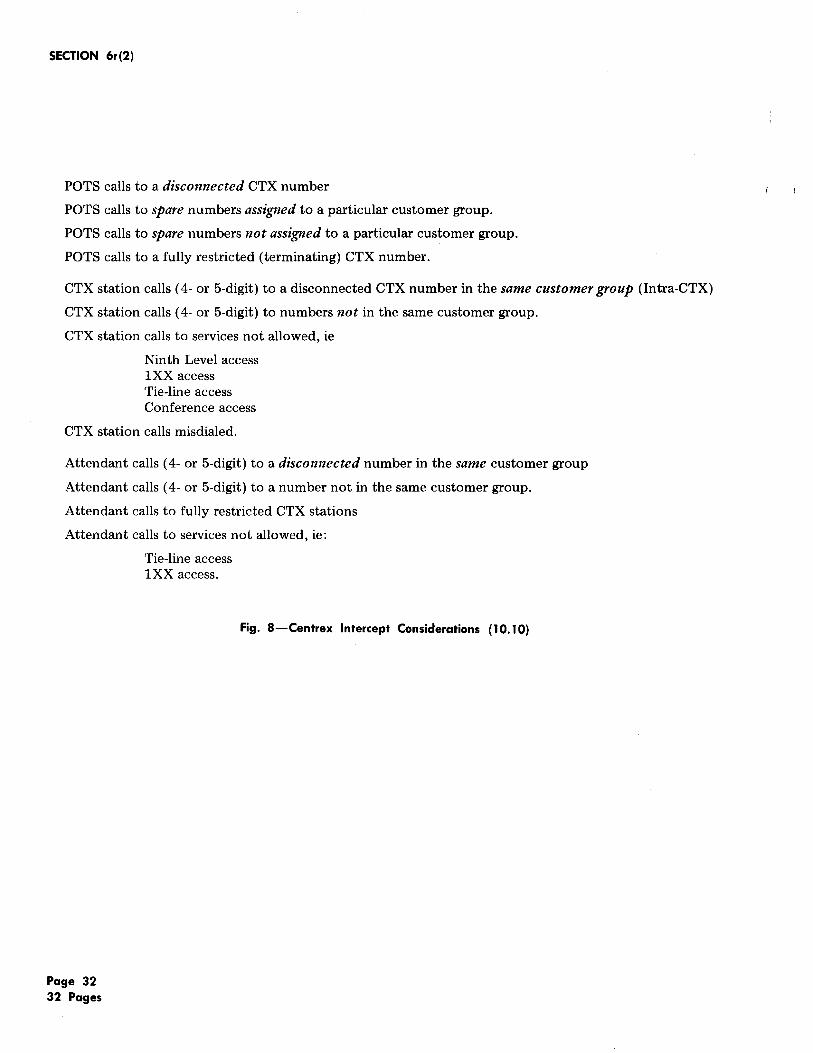
POTS calls to a disconnected CTX number
POTS calls to spare numbers assigned to a particular customer group.
POTS calls to spare numbers not assigned to a particular customer group.
POTS calls to a fully restricted (terminating) CTX number.
CTX station calls ( 4- or 5-digit) to a disconnected CTX number in the same customer group (Intra-CTX)
CTX station calls ( 4- or 5-digit) to numbers not in the same customer group.
CTX station calls to services not allowed, ie
Ninth Level access lXX access Tie-line access Conference access
CTX station calls misdialed.
Attendant calls ( 4- or 5-digit) to a disconnected number in the same customer group
Attendant calls ( 4- or 5-digit) to a number not in the same customer group.
Attendant calls to fully restricted CTX stations
Attendant calls to services not allowed, ie:
Page 32 32 Pages
Tie-line access lXX access.
Fig. 8-Centrex Intercept Considerations (10.10)


![CUBE Media Proxy - Cisco · media-recording proxy [dial-peer-tag1 dial-peer-tag2 dial-peer-tag3 dial-peer-tag4 dial-peer-tag5] Example: Step4 Note Youcanspecifymaximumoffivedial-peertags.](https://static.fdocuments.net/doc/165x107/600896c15662324ac908e474/cube-media-proxy-cisco-media-recording-proxy-dial-peer-tag1-dial-peer-tag2-dial-peer-tag3.jpg)