DIAL FACILITIES MANAGEMENT PRACTICES …etler.com/docs/DFMP/H/DFMP-H-1b(9)_I2.pdf · SWITCHING...
23
DIAL FACILITIES MANAGEMENT PRACTICES AT & TCo Standard DIViSION H SECTION 1b(9) Issue 2, November 1976 SWITCHING SYSTEMS MANAGEMENT ADMINISTRATION DETERMINATION OF LINE AND NUMBER REQUIREMENTS CONTENTS PAGE 1. GENERAL 2 2. RESPONSIBILITIES 2 3. ADMINISTRATIVE LINE REQUIREMENTS 3 4. LINE UTILIZATION MONTHLY RECORD 3 S. CLASS OF SERVICE ADJUSTMENT NO. AND NO. S CROSSBAR 6. DERIVATION OF PERCENT LINE FILL AND CAPACITY DETERMINATION 7. NUMBER REQUIREMENTS 8. NUMBER UTILIZATION MONTHLY RECORD A. Guidelines for Intercept of Unassigned Numbers B. Accelerated Reassignment Guidelines C. Intercept Study D. Determining Intercept Number Requirements E. Intercept Number Requirements F. Reassignment of Intercepted Numbers 9. NUMBER UTILIZATION ADMINISTRATIVE FACTOR 10. DERIVATION OF PERCENT NUMBER FILL 3 4 4 4 s 6 6 6 7 7 7 CONTENTS PAGE AND CAPACITY DETERMINATION 7 Figures 1. Line Capacity Determination (Sample Work 9 2. Line Utilization Monthly Work Sheet-Service Year (Sample) 10 3. Line Utilization Class of Service Adjustment No. 1 and No. S Crossbar (Sample Form) 4. Telephone Number Remarks Space Entries S. Number Capacity Determination (Sample 11 12 Form) 13 6. Number Utilization Monthly Work Sheet (Sample Form) 14 7. Number Utilization Administrative Factor (Sample Form) 1 S Tables A. Intercepting Intervals Accelerated Reassignment Plan 16 B. Intercepting Intervals Reassignment Plan 16 NOTICE 006-052 Not for use or disclosure outside the Bell System except under written agreement Printed in U.S.A. Page 1
Transcript of DIAL FACILITIES MANAGEMENT PRACTICES …etler.com/docs/DFMP/H/DFMP-H-1b(9)_I2.pdf · SWITCHING...

DIAL FACILITIES MANAGEMENT PRACTICES AT & TCo Standard
DIViSION H SECTION 1b(9)
Issue 2, November 1976
SWITCHING SYSTEMS MANAGEMENT
ADMINISTRATION
DETERMINATION OF LINE AND NUMBER REQUIREMENTS
CONTENTS PAGE
1. GENERAL 2
2. RESPONSIBILITIES 2
3. ADMINISTRATIVE LINE REQUIREMENTS 3
4. LINE UTILIZATION MONTHLY RECORD 3
S. CLASS OF SERVICE ADJUSTMENT NO. AND NO. S CROSSBAR
6. DERIVATION OF PERCENT LINE FILL AND CAPACITY DETERMINATION
7. NUMBER REQUIREMENTS
8. NUMBER UTILIZATION MONTHLY RECORD
A. Guidelines for Intercept of Unassigned Numbers
B. Accelerated Reassignment Guidelines
C. Intercept Study
D. Determining Intercept Number Requirements
E. Intercept Number Requirements
F. Reassignment of Intercepted Numbers
9. NUMBER UTILIZATION ADMINISTRATIVE FACTOR
10. DERIVATION OF PERCENT NUMBER FILL
3
4
4
4
s
6
6
6
7
7
7
CONTENTS PAGE
AND CAPACITY DETERMINATION 7
Figures
1. Line Capacity Determination (Sample Work ~~ 9
2. Line Utilization Monthly Work Sheet-Service Year (Sample) 10
3. Line Utilization Class of Service Adjustment No. 1 and No. S Crossbar (Sample Form)
4. Telephone Number Remarks Space Entries
S. Number Capacity Determination (Sample
11
12
Form) 13
6. Number Utilization Monthly Work Sheet (Sample Form) 14
7. Number Utilization Administrative Factor (Sample Form) 1 S
Tables
A. Intercepting Intervals Accelerated Reassignment Plan 16
B. Intercepting Intervals Reassignment Plan 16
NOTICE
006-052
Not for use or disclosure outside the Bell System except under written agreement
Printed in U.S.A. Page 1

SECTION 1b(9)
1. GENERAL
1.01 The administration of central office equipment should ensure good service and the most
effective utilization of the switching equipment. Local switching system capacities are separated into three general categories:
(a) Lines
(b) Numbers
(c) Switching (major portion of the investment).
1.02 This section is being reissued to update forms and incorporate comments received
from operating telephone companies on Issue 1.
1.03 It is economically unsound to allow the least expensive items of equipment to be the
capacity limiting items of an office. Lines and numbers represent a relatively small percentage of the total central office investment. An adequate supply of these items of equipment should be provided.
1.04 It is recommended that the administrative requirements for lines, and the administrative
factor for numbers, be determined empirically for each office by the procedures herein rather than by using a fixed percentage.
1.05 This section includes (a) the items which should be considered when determining
requirements for proper line and number fill in an office, (b) suggested methods of accumulating pertinent data, and (c) sample forms and charts to direct those activities. (Note: Full size forms of Figures 1, 2, 3, 5, 6, and 7 are attached to this section on unnumbered pages for local reproduction purposes.) The purpose of the section is to guide the administrator in determining the proper fills and the proper provision of lines and numbers. The administration can then assist in determining the capacity of the switching system.
1.06 Local relief jobs should be engineered to last an appropriate period of time, with full
consideration given to service, data, and economics. Local conditions and the use of the Central Office Equipment Estimation System (COEES), where appropriate, will help determine the appropriate job sizing and timing. Experience, good judgment, and close cooperation on the part of
Page 2
the network administrator and the network designer are vital to assure that relief job timing meets the demands of the customers. Switching capacity should carry through the last busy season in the engineering period with service results which do not exceed engineering service objectives. Line and number capacity should be provided to last beyond the exhaust date of the switching equipment at a fill which allows for adequately meeting administrative needs. This should provide the physical flexibility to cover slight changes in commercial estimates, schedule changes, etc, and assure full use of switching equipment.
1.07 Careful attention to the procedures described herein will also assure that network designers
have the necessary information prescribed in the appropriate Traffic Facilities Practices for the provisioning of lines and numbers.
1.08 The procedures prescribed herein for establishing main station capacities (Line 11,
Fig. 1 and Line 16, Fig. 5) are compatible with the instructions for preparing standard Demand and Facility Charts and the Dial Office Load Service Report.
2. RESPONSIBILITIES
2.01 The network administrator shquld provide input for determining the quantity of lines
and numbers needed to properly administer an office. The administrator should be an active member of the team that determines the amount of equipment required. This judgment should be predicated on empirical data compiled through regularly scheduled studies. An accurate office profile is essential to decision making. The areas which need to be documented are:
(1) The quantity of equipments to meet number aging requirements.
(2) Office growth (lines and numbers).
(3) Available line equipments required to permit proper class of service distribution and load
balance techniques.
( 4) Lines and numbers required to maintain advance assignment lists.

(5) The quantity of equipments withheld from general assignment and dedicated to special
administrative needs.
3. ADMINISTRATIVE LINE REQUIREMENTS
3.01 The provision of sufficient lines is of vital importance. Shortages of line equipment
make load and class of service balance procedures more difficult, necessitate more line equipment transfers, and require more frequent assignment lists.
4. LINE UTILIZATION MONTHLY RECORD
4.01 The network administrator should conduct studies on a continuing basis to determine
the line utilization in an office. These studies can be used to compute the derived percent line fill. Fig. 2 may be used to record the line utilization each month. In offices such as No. 2 Electronic Switching System (ESS), certain types of trunks and junctors are assigned to line terminations. The quantity of such terminations provided and engineered for these purposes may be recorded on a form similar to (Fig. 2) line 2 and is excluded from the total lines available for assignment to customers in calculating the derived percent line fill.
4.02 Administrative unusable lines include the following:
(a) Automatic dial tone speed test lines (not to be fewer than specified in the Traffic
Service Observing Practices, Division F, Section 2b)
(b) Plant test lines (not including those that are temporary or used intermittently, such
as special call-through-testing arrangements)
(c) Reservations and assignments over 30 days
(d) Assignment lists
(e) Other administrative requirements, such as restrictions caused by class of service, special
service offerings, screening LEN, etc.
4.03 Assignment lists (Fig. 1, line 5) will vary from location to location. The size of each
DIVISION H, SECTION 1b(9)
assignment list will be determined by evaluating the input of the following items on the list:
(a) Inward movement per line gained ratio for the office.
(b) Transit time of list to user.
(c) Installation interval.
(d) Transit time of completed order to network administrator.
(e) Unigauge.
(f) Zoned main distributing frames.
(g) Line equipment shortages.
(h) Load balance
(i) Additions or area transfer for central office switching relief.
(j) Growth rate of the area.
(k) Modular frames
4.04 Other administrative requirements (Fig. 1, line 6) are a total of other line
restrictions resulting from individual office configurations other than items 2 through 5, for which there are forseeable needs preventing their use for customer assignment; eg, these requirements are reserved for (1) Company official lines, (2) line equipments for other features, such as range extension, automatic identification of outward dialing (AIOD), and (3) lines that are impracticable to modify for other uses.
5. CLASS OF SERVICE ADJUSTMENT NO. 1 AND NO. 5 CROSSBAR (Fig. 3)
5.01 The class of service adjustment is a count of working lines separated by class of service
and type of pulsing, ie, dial pulse (DP) and TOUCH-TONE®, as of the most current month, and read into the table on Fig. 3. This should provide sufficient equipment to every class to permit proper load balance and class of service distribution.
Page 3

SECTION 1b(9)
6. DERIVATION OF PERCENT LINE FILL AND CAPACITY DETERMINATION
6.01 For the purposes of calculating and using the derived percent line fill, the total lines
are defined as the total lines installed. Offices with multiple size line link frames (LLFs) loaded to a low percentage of line fill can achieve an equal spread of lines by considering all LLFs as having no more line relays than the smallest LLF, eg, in an office with ten 490s and four 590s, all14 frames can be considered as being the 490 size. This is the preferred method from an administration point of view. This multiple size LLF operation should be avoided and, whenever possible, corrected on the next addition. However, when additions are not contemplated and there is a high line fill, the one size approach may prove to be impractical. An extreme procedure to compensate for this problem is to assign heavy usage lines to smaller frames and light lines to larger frames. In this manner, it is possible to allow each frame to carry the same total load (CCS/LLF). Normally, this is not a recommended procedure and balance by class of service is still an important consideration and must be maintained. The detailed procedure for this can be found in the Dial Facilities Management Practices, Division H, Sections 4d(4) and 5d(4).
6.02 The main station capacity as limited by lines can be calculated by using Fig. 1.
6.03 Fig. 2 and 6 illustrate a suggested form and instructions for gathering historical data
for use in determining the percent line capacity. The capacity and exhaust of an office should be recalculated whenever significant changes occur in the forecast or in any other item of the work sheet.
6.04 The capacity, then, is the portion of total equipped lines can be used by customers.
The percent of line capacity is the degree to which these lines have been utilized. The optimum situation is when the percent of line capacity reaches, but does not exceed, 100 percent between relief jobs. To exceed 100 percent potentially results in insufficient line equipments for efficient line assigning procedures, improper utilization of some reserves, and inability to correct imbalance or maintain short jumper objectives on ESS or zoned non-ESS main distributing frames. In an extreme instance this could cause held orders.
Page 4
7. NUMBER REQUIREMENTS
7.01 Basic Guidelines: One of the controlling factors in the determination of number
requirements in an office is the quantity of numbers needed to provide adequate intercept intervals. A sufficient quantity should be available to ensure good customer service and prevent numbers from being the limiting item of equipment.
7.02 The objective is to have enough numbers in an office to allow compliance with the System
recommendation for aging changed and disconnected numbers, as well as enough to cover administrative unusables during periods of peak station movement. Good customer service demands that a number be relatively free from incoming calls intended for the previous customer before being reassigned.
8. NUMBER UTILIZATION MONTHLY RECORD (Fig. 6)
8.01 The network administrator should prepare studies on a continuing basis to determine
the number utilization in an office. These studies can be used to compute the percent number fill. Fig. 6 may be used to record this number utilization each month. In offices such as No. 5 crossbar, wherein certain types of trunks and junctors are assigned numbers, the quantity provided and engineered for these purposes is recorded on Fig. 6, line 2, and is excluded from the total available for assignment to customers in calculating the derived percent number capacity.
8.02 Administrative unusable numbers include the following:
(a) Numbers dedicated to special service, OFFICIAL and COIN, for which there is no
demand prior to the next addition of numbers
(b) Numbers dedicated for plant test
(c) Numbers reserved for specific customers with a written or verbal reservation from
the Commercial or Marketing Departments
Note: Verbal reservation should normally be confirmed in writing within a reasonable time period.

(d) Numbers reserved for business customer growth (centrex, PBX, hunting service, etc)
and former high users (bars, taxi company, etc)
(e) Assignment lists
(f) Numbers on intercept
(g) When the load on a SXS connector group is equal to or greater than the engineered
capacity for two consecutive months based on an average group usage for five consecutive business days, any nonworking numbers may be considered unusable. The records of these connector groups should be marked to indicate the current status. A suggested method of doing this is with color-coded adhesive paper, ie, a small red dot for do not assign (at or above capacity) and a small yellow dot for caution (within 10 CCS of capacity). The groups that are 10 or more CCS below capacity (not marked) may be considered to be satisfactory for judicious assignment. If all connector groups become overloaded, then other indicators such as all connector busy peg count or equivalent may be used. It may be necessary to hold orders pending relief. This would be an executive decision. The same basic approach should be applied in panel offices.
8.03 The number entered on line 9, Fig. 6, assignment lists, may not reflect the
optimum quantity of telephone numbers required when a shortage exists. In addition to other considerations, the entry should show the quantity of telephone numbers needed to achieve the necessary service order flow for efficient departmental and interdepartmental manpower requirements.
A. Guidelines for Intercept of Unassigned Numbers
8.04 The guidelines for intercept of unassigned numbers are as follows:
(a) Unused Number(s)
All unused numbers will be intercepted until needed. No minimum time period is required.
The introduction of the Automatic Intercept System (AIS) imposes an additional criteria for directory number administration.
DIVISION H, SECTION 1 b(9)
Intercepted numbers are stored in AIS memory in either single entries for hundred number blocks or individually by number. Hence, while a spare hundred block requires only one memory entry, a block with only a few working numbers will require an individual entry for each of the unassigned numbers. Indiscriminate assignment of directory numbers can result in premature exhaustion of the memory capacity of an AIS.
Dial Bureaus should insure themselves of a reasonable fill in each existing hundred block before opening a new one for assignment. While some exceptions may exist due to number reservation, a general figure of 75 percent fill of each hundred block should be used.
(b) Residence Disconnect and Changes
A number must be intercepted for a minimum of three months from the date of disconnect or change.
(c) Business Disconnect or Change
A number must be intercepted for a minimum of twelve months from the date of disconnect/change or while listed in the current directory, whichever is longer.
(d) Centrex CO Stations
A number should be intercepted for one month or less from the date of disconnect or change. This may be negotiated with the customer and the marketing representative.
8.05 Quite often, a well known and frequently called number is considered unassignable
for an indeterminate period, and is not reassigned without a study. It is desirable that arrangements be made locally for Customer Services to advise Network Administration when a disconnected number might require special handling-eg, numbers that have served a taxi company, a large store, a public service, etc, or numbers listed incorrectly in the directory.
Page S

SECTION 1 b(9)
B. Accelerated Reassignment Guidelines
8.06 No office should be so short of numbers as to necessitate reassignment
in less than the system-prescribed interval. However, if necessary, the numbers selected for intercept studies should never be those businesses which subscribe to Yellow Pages advertising until after the last directory in which the customer advertising appears, has expired. These customers' charges may continue despite the disconnection of service; release of the number through the Commercial Department is required before reuse within a directory period.
8.07 When it becomes necessary to reassign numbers before the prescribed minimum
aging interval has lapsed, steps must be taken to minimize the adverse reaction from customers.
(a) All usused numbers will be used first. It is more desirable to open a new hundred in
AIS than to use accelerated reassignment guidelines. No intercept study is required.
(b) A number will not be reassigned while it is listed in the records used by the directory
assistance operator.
(c) All other numbers will be reassigned in the following manner:
(1) Those locations that cannot make mechanized intercept studies and do not
choose to make manual intercept studies may use table A.
(2) Those locations that can make mechanized intercept studies or choose to make manual
studies may use table B.
C. Intercept Study
8.08 Whenever the intercept intervals recommended in paragraph 8.04 cannot be adhered to and
it is necessary to reassign numbers in less than the prescribed period, a study of incoming call volume may be necessary to determine which number will be made available for reassignment.
8.09 The study will be conducted for a 7-day period in central office codes (NNXs) where
there is a serious shortage of available numbers.
Page 6
The recommended procedure for taking the study is as follows:
(1) Manual Intercept Study
(a) All numbers selected for study must be routed to operator intercept. It may be
necessary to change the wiring on numbers to route them to the intercept operator.
(b) When an entire NNX is to be studied, the operator will be advised through use
of a feature card by having each page stamped INTERCEPT STUDY.
(c) Where less than a NNX is to be studied, the selected numbers can be identified by
the printer of the intercept records. A code, such as an asterisk, will be entered alongside the number and remain in the record for the duration of the study.
(d) Whenever a report is given on a coded number, the operator places a tally beside
the number in the record.
(2) Mechanized Intercept
Where the system-standard AIS is used, a program is provided which simplifies the mechanics of the study. After identifying the numbers to be studied, the AIS provides a printout listing the intercepted numbers having two or less calls during the 7-day period.
8.10 At the completion of the intercept study, results will be compiled showing the total
numbers of calls received for each number during the 7 -day period.
D. Determining Intercept Number Requirements
8.11 The network administrator needs to know the intercept number requirements for each
office, if an adequate supply of numbers is to be provided, to assure that customers receive the proper intercept treatment. The effect of all intercept restrictions must be reflected in the determination of number requirements. For example, residence disconnects require three months of intercept before reassignment. Therefore, each month the three previous months' disconnects are held as unassignable numbers.

E. Intercept Number Requirements
8. 12 To determine the status of intercepted numbers, it will be necessary for the network
administrator to maintain a detailed monthly record of disconnects and changes (Fig. 6). These divisions are necessary if the appropriate intercept intervals are to be maintained, based on the type of service and the status of the released number.
8. 13 Fig. 6 and 7 illustrates the recommended method of ascertaining the required intercept
margin. It is based on monthly service order activity. If records are not available for all of the 12 months prior to the starting month of this form, no true total for the monthly count of numbers on intercept will be available for one year. However, if six months' or three months' records were available, the count would be usable after six months or three months, respectively. During initial implementation of these procedures, it may be necessary to estimate these requirements.
8. 14 There are two classifications to be counted monthly:
(a) Business Change/Disconnect
(b) Residence Change/Disconnect
Note: Centrex CO stations may be counted as residence.
Fig. 6 illustrates the method of maintaining the monthly intercept activity. Recording intercept activity in this manner will enable the network administrator to determine the quantity of numbers receiving intercept service.
F. Reassignment of Intercepted Numbers
8.15 Record Entries: It is standard procedure to date all changed or disconnected number
entries in the number assignment records. This date is pertinent when selecting numbers for reassignment since it has always been the practice to reuse numbers in progression, starting with the oldest disconnect date, hut subject to paragraph 8.04.
8.16 In keeping with the recommendation for aging numbers set forth in paragraph 8.04,
it will be necessary to know whether the disconnected
DIVISION H, SECTION 1b(9)
or changed number was formerly assigned to a business or a residence. Fig. 4 illustrates the recommended assignment entdes. These remarks are compatible with the ESS offices, ie, they have 17 or less alphanumerical characters.
8.17 The date associated with a number may remain in the record until reassignment,
since continual clearing of records is time consuming. Although a number may have met the minimum intercept requirements, the date will still be a guide in reassignment. There is always an advantage to the customer when the length of time a number has been out of service is a consideration in reassignment.
8.18 The use of an intercept column in the assignment records is recommended to indicate
the period of intercept service. It will expedite the assigner's job when preparing lists of numbers for assignment in that an entry in the column will be a criterion for selecting numbers. If all numbers are available, each disconnect date must be evaluated and every effort should be made to assign the oldest disconnect.
9. NUMBER UTILIZATION ADMINISTRATIVE FACTOR
9.01 The number utilization administrative factor is the ratio of the main stations working to
the telephone numbers required for the recommended intercepting intervals plus the numbers required for assignment lists. Fig. 7 illustrates the recommended format and contains the instructions for use in determining the administrative factor.
10. DERIVATION OF PERCENT NUMBER FILL AND CAPACITY DETERMINATION (Fig. 5)
10.01 The main station capacity as limited by number can be calculated by using Fig. 5.
10.02 Each office and each rate zone within an office should be computed separately to
ensure the proper provision of telephone numbers. The derived percent number fill determination portion should be calculated at least annually and forwarded to network design. The official calculations should be based on the service year.
10.03 The exhaust data portion (Lines 17 through 22) of Fig. 5 is intended for administrative
use and should be calculated whenever significant
Page 7

SECTION lb(9)
changes occur in the forecast or any other item of the work sheet.
10.04 Since some types of central office systems require dedicated groups of telephone
Page 8
numbers for various classes of service (eg, coin, level hunting, etc), each group of dedicated numbers must be examined throughly to identify and compensate for any surplus or deficiencies that may exist.

INSTRUCTIONS FOR FIG.1-LINE CAPACITY DETERMINATION
CAPACITY DETERMINATION
Line 1 - Equipped Lines
Line 2 - Dedicated to Trunks and Junctors
Line 3- Test
Line 4 - Reservation and Assignments over 30 Days
Line 5 - Assignment Lists
Line 6 - Other Administrative Requirements
Line 7 - Class of Service Adjustment
Line 8- Workable Lines (Line Capacity)
Line 9 - Derived % Line Fill
Line 10- MS to Line Ratio
Line 11 - MS Capacity as Limited by Lines
The quantity of equipped line relays. In No.5 Crossbar offices, the number of LLF times the size of the frame. Example: 490 size x 5 LLF = 2450 lines. Show the actual installed lines in the space above line 1. In entities where separate loading divisions exist, list each loading division in a separate column.
In offices that have line appearances dedicated to trunks and junctors.
The quantity of line appearances being used for dial tone speed test lines, plant test lines, etc. From line 3, Fig. 2. (Latest month posted.)
The average quantity of line equipments on reservation or assignment over 30 days. From line 4, Fig. 2.
The total quantity of line equipments assigned during the three highest consecutive months of the previous year divided by 6. From line 5, Fig. 2.
Total of other line restrictions resulting from individual office configurations. From line 6, Fig. 2. Example: screening LEN No. 1 ESS.
Total Dial Pulse and TOUCH-TONE adjustments. From Fig. 3.
Line 1 minus lines 2, 3, 4, 5, 6, and 7. Where separate loading divisions exist, a separate work sheet should be maintained for each loading division for lines 1 through 7.
[Line 8 divided by (line 1 minus line 2)] by 100.
Total office only. Use most current ratio from line 7, Fig. 2, or the projected exhaust date ratio from the forecast, whichever is greater.
[(Line 1 minus line 2) x line 9] x line 10. Total office onlyMS as limited by lines is for total office only. Individual loading divisions need to be calculated separately for administration by class of service and establishing exhaust dates.
DIVISION H, SECTION 1b{9)
LINE CAPACITY DETERMINATION
ENTITY----------------DATE ____________ __ TYPE ___________ _
A.
B.
LOADING DIVISIONS
TOTAL OFFICES
CAPACITY DETERMINATION
1. Equipped Lines
2. Dedicated to Trunks and Junctors
3. Test
4. Reservations and Assignments Over 30 Days
5. Assignment Lists
6·. Other Administrative Requirements
7. Class of Service Adjustment
8. Workable Lines ( L1 Minus L2, 3, 4, 5, 6, and 7)
9. Derived% Line Fill [L8-;- (L1- L2)] X 100
10. MS to Line Ratio (Line 7, Fig. 2)
11. MS Capacity as Limited by Lines [(L1- L2) X L9] X (L10-;- 100)
EXHAUST DATA
12. Working MS as of
13. Available Main Stations (L11 Minus L12)
14. Forecasted MS Growth/Month
15. Exhaust Date
16. Relief Date
Fig. 1-Line Capacity Determination (Sample Work Sheet)
Page 9
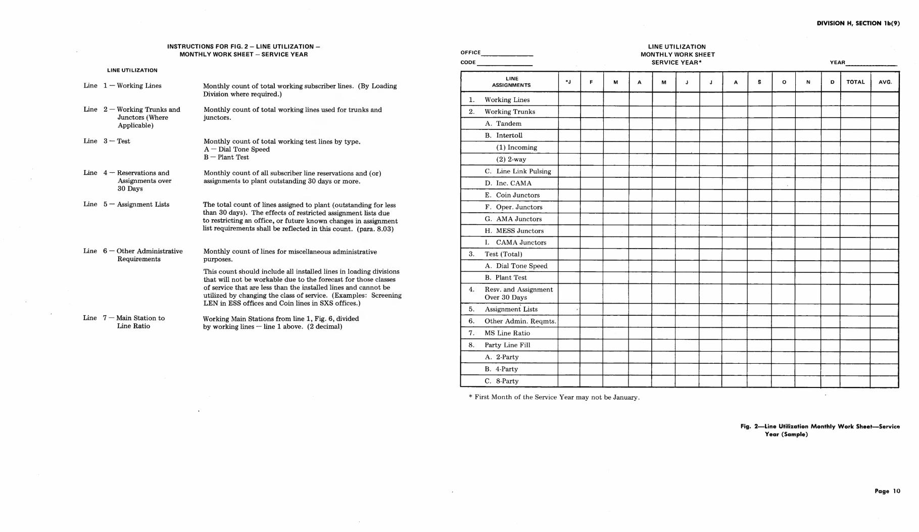
INSTRUCTIONS FOR FIG. 2- LINE UTILIZATIONMONTHLY WORK SHEET- SERVICE YEAR
LINE UTILIZATION
Line 1 -Working Lines
Line 2- Working Trunks and Junctors (Where Applicable)
Line 3- Test
Line 4- Reservations and Assignments over 30 Days
Line 5 - Assignment Lists
Line 6 - Other Administrative Requirements
Line 7 - Main Station to Line Ratio
Monthly count of total working subscriber lines. (By Loading Division where required.)
Monthly count of total working lines used for trunks and junctors.
Monthly count of total working test lines by type. A- Dial Tone Speed B- Plant Test
Monthly count of all subscriber line reservations and (or) assignments to plant outstanding 30 days or more.
The total count of lines assigned to plant (outstanding for less than 30 days). The effects of restricted assignment lists due to restricting an office, or future known changes in assignment list requirements shall be reflected in this count. (para. 8.03)
Monthly count of lines for miscellaneous administrative purposes.
This count should include all installed lines in loading divisions that will not be workable due to the forecast for those classes of service that are less than the installed lines and cannot be utilized by changing the class of service. (Examples: Screening LEN in ESS offices and Coin lines in SXS offices.)
Working Main Stations from line 1, Fig. 6, divided by working lines -line 1 above. (2 decimal)
OFFICE ______ _
CODE ______ _
LINE ASSIGNMENTS
1. Working Lines
2. Working Trunks
A. Tandem
B. Intertoll
(1) Incoming
(2) 2-way
C. Line Link Pulsing
D. Inc . CAMA
E. Coin J unctors
F . Oper. Junctors
G . AMA Junctors
H . MESS Junctors
I. CAMA Junctors
3. Test (Total)
A. Dial Tone Speed
B. Plant Test
4. Resv. and Assignment Over 30 Days
5. Assignment Lists
6. Other Admin. Reqmts.
7. MS Line Ratio
8. Party Line Fill
A. 2-Party
B. 4-Party
c. 8-Party
*J F M
LINE UTILIZATION MONTHLY WORK SHEET
SERVICE YEAR*
A M J J
* First Month of the Service Year may not be January .
A
DIVISION H, SECTION 1 b(9)
YEAR _________ _
s 0 N 0 TOTAL AVG.
Fig. 2-Line Utilization Monthly Work Sheet-Service Year (Sample)
Page 10

LINE UTILIZATION- CLASS OF SERVICE ADJUSTMENT NO. 1 AND NO. 5 CROSSBAR
ENTITY ______ _
YEAR RATE ZONE NNX
NUMBER WORKING
CLASS OF SERVICE DP IN DP GROUPS DP/TT IN TT GROUPS
1 FR
2 FR
2MR
4-PARTY
8-PARTY
MANUAL
COIN
PBX
1 FB
2 FB
MB
PBX
TOLL CONTROL
WATSBANDO
1
2
3
4
5
INTRASTATE WATS
TWX
TYPE
ADJUSTMENT
DP TT
(Cont)
DIVISION H, SECTION 1 b(9)
LINE UTILIZATION- CLASS OF SERVICE ADJUSTMENT NO.1 AND NO.5 CROSSBAR
(Cont}
QUANTITY WORKING ADJUSTMENT CLASS OF SERVICE
DP IN DP GROUPS DP/TT IN TT GROUPS DP TT
CENTREX RATE TREATMENTS
OTHER
TOTAL
INSTRUCTIONS
The annual count of working lines separately by DP and TT for most current month read into the following table to determine the adjustment
OBJECTIVE QUANTITY OF SPARE LINE EQUIPMENT TERMINALS (MINIMUM!
QUANTITY OF WORKING QUANTITY OF LINE LINK FRAMES IN THE CONTROL GROUP {ENTITY! EQUIPMENT IN A
CLASS OF SERVICE 2-10 11-20 21-30 31-40 41-50 51-60
10- 49 5 8 11 14 17 20 50- 199 10 15 20 25 30 35
200- 499 15 20 35 50 65 80 500-1,499 20 40 60 80 100 120
1,500- 4,999 * 1% * 1% 75 105 135 165 5,000- 9,999 * 1% * 1% 100 140 180 220
10,000 & Over * 1% 125 175 225 275
*Maintain Minimum of 1% in the most frequently used class of service.
Fig. 3--line Utilization Class of Service Adjustme~o. 1 and No. 5 Crossbar (Sample Form)
Page 11

DIVISION H, SECTION 1 b(9)
TEL. NUMBER REMARKS SPACE ENTRIES EXPLANATION
1 - 1000 Hz test #, etc.
2-RES
3-D 7-10-74 T/C
4- RD 9-1-74 T/C
5- C 10-2-74 T/C
6- RC 11-1-74 T/C
7- D 11-2-74 No T/C
8- RD 11-3-74 No T/C
9- C 11-4-74 No T/C
10- RC 11-5-74 No T/C
11- PLT ASSGN
12 -NON-PUB D
13-EL
14- Nite Svc
15-LDN
16-MAN
17- INTC. 'til1-1-75
18-BTN
19- DLL
20-DNA
21 -NON-PUB C
22- RE 11-15-74 T/C
23- BN 10-2-74 No T/C
Reserved
Business Disconnect Referral of Calls
Residence Disconnect Referral of Calls
Business Change Referral of Calls
Residence Change Referral of Calls
Business Disconnect No Referral of Calls
Residence Disconnect No Referral of Calls
Business Change No Referral of Calls
Residence Change No Referral of Calls
Plant Assignment
Nonpublished Disconnect
Essential Service
Night Service
Listed Directory Number
Manual Line
Intercept until 1-1-75
Bill to Number
Dial Long Lines
Do Not Assign
Nonpublished Change
Residence Change Company Initiated Life of Directory
Business Disconnect or Change, Nonlisted, No Referral
Fig. 4-Telephone Number Remarks Space Entries
Page 12

INSTRUCTIONS FOR FIG. 5- NUMBER CAPACITY DETERMINATION
Line 1 - Total Equipped Numbers
Line 2 - Dedicated Trunks
Line 3 - Dedicated Special Services
Line 4 - Dedicated official and Test Numbers
Line 5 - Dedicated Coin Numbers
Line 6 - Reservations-Subscriber
Line 7 - Reserved - Nonusable
Line 8-10
Line 11 _ Working Special Services+ Forecasts
Line 12- Working Official +Forecast
Line 13- Working Coin +Forecast
Line 14-
Line 15 - Derived % No. Fill
Total quantity of installed numbers. Number groups used solely for trunks are not included.
The quantity of numbers set aside for use by trunks, coin junctors, etc, included on line 1.
The quantity of numbers set aside for use by special services such as INWATS TWX, etc.
The quantity of numbers set aside for official and test numbers (Usually the 9900 bank for official.)
The quantity of numbers set aside for coin use only.
The quantity of reserved numbers from most recent count on line 7, Fig. 6.
Previous year average quantity of numbers reserved for hunting group. From line 8, Fig. 6.
Self-explanatory
Quantity of working special services included in the main station count from most current monthly count on line 3, Fig. 6, plus forecasted growth to the end of the engineering period.
Quantity of working dedicated official numbers included in the main station count from most current monthly count on line 4, Fig. 6, plus forecasted growth to the end of the engineering period. Quantity of working coin stations included in the main station count from most current monthly count on line 6, Fig. 6, plus forecasted growth to the end of the engineering period. Self-explanatory
Line 14 divided by [total equipped numbers (line 1) minus dedicated trunks (line 2)] to one decimal.
DIVISION H, SECTION 1 b(9)
NUMBER CAPACITY DETERMINATION
ENTITY---------------DATE _________ _ TYPE ______ ___
1.
2.
3.
4.
5.
6.
7.
8.
9.
10.
11.
12.
13.
14.
15.
16.
17.
18.
19.
20.
21.
Total Equipped Numbers
Dedicated Trunks
Dedicated Special Services
Dedicated Official and Test
Dedicated Coin Numbers
Reservations - Subscriber
Reserved- Nonusable
Subtotal (L1 Minus L2, 3, 4, 5, 6 & 7)
Administrative Factor (L6, Fig. Ty
Assignable Noncoin (L9 X L8)
Working Special Services No. +Forecasts
Working Official No. + Forecasts
Working Coin No. +Forecasts
Subtotal (L10+ L11 + L12+ L13)
Derived % Number Fill [L14 + (L1 - L2)] X 100
Main Station Capacity as Limited by Numbers [(L1- L2) X L15 + 100)]
Working MS as of
Avail. Numbers (L16-L17)
Forecasted Growth Ms/Month
Exhaust (Ll8 + L19) Date
Relief Date
TOTAL OFFICES
Fig. 5-Number Capacity Determination (Sample Form)
Page 13
Line 1
Line 2A-J
Line 3A-C
Line 4
Line 5
Line 6
Line 7
Line 8
Line 9
Line 10
Line 11
Line 12
Line 13
Line 14
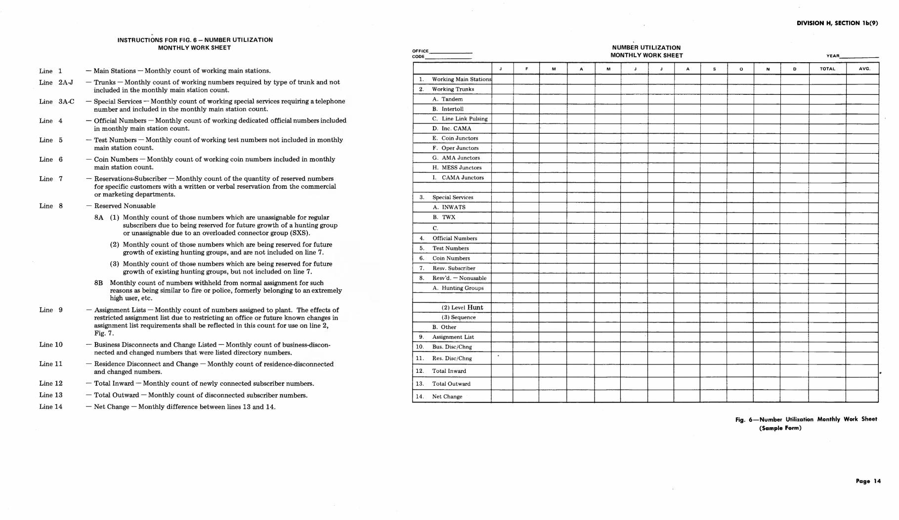
INSTRUCTIONS FOR FIG. 6- NUMBER UTILIZATION MONTHLY WORK SHEET
- Main Stations -Monthly count of working main stations.
- Trunks - Monthly count of working numbers required by type of trunk and not included in the monthly main station count.
- Special Services - Monthly count of working special services requiring a telephone number and included in the monthly main station count.
- Official Numbers- Monthly count of working dedicated official numbers included in monthly main station count.
-Test Numbers- Monthly count of working test numbers not included in monthly main station count.
- Coin Numbers- Monthly count of working coin numbers included in monthly main station count.
- Reservations-Subscriber - Monthly count of the quantity of reserved numbers for specific customers with a written or verbal reservation from the commercial or marketing departments.
- Reserved Non usable
SA (1) Monthly count of those numbers which are unassignable for regular subscribers due to being reserved for future growth of a hunting group or unassignable due to an overloaded connector group (SXS).
(2) Monthly count of those numbers which are being reserved for future growth of existing hunting groups, and are not included on line 7 .
(3) Monthly count of those numbers which are being reserved for future growth of existing hunting groups, but not included on line 7.
8B Monthly count of numbers withheld from normal assignment for such reasons as being similar to fire or police, formerly belonging to an extremely high user, etc.
- Assignment Lists -Monthly count of numbers assigned to plant. The effects of restricted assignment list due to restricting an office or future known changes in assignment list requirements shall be reflected in this count for use on line 2, Fig. 7.
- Business Disconnects and Change Listed - Monthly count of business-disconnected and changed numbers that were listed directory numbers.
- Residence Disconnect and Change - Monthly count of residence-disconnected and changed numbers.
- Total Inward - Monthly count of newly connected subscriber numbers.
- Total Outward - Monthly count of disconnected subscriber numbers.
-Net Change- Monthly difference between lines 13 and 14.
OFFICE _____ _
CODE
1. Working Main Stations
2. Working Trunks
A. Tandem
B. lntertoll
c. Line Link Pulsing
D. Inc. CAMA
E. Coin Junctors
F. Oper Junctors
G. AMA Junctors
H. MESS Junctors
I. CAMA Junctors
3. Special Services
A. INWATS
B. TWX
c. 4. Official Numbers
5. Test Numbers
6. Coin Numbers
7. Resv. Subscriber
8. Resv 'd. - Nonusable
A. Hunting Groups
(2) Level Hunt
(3) Sequence
B. Other
9. Assignment List
10. Bus. Disc/Chng
11. Res. Disc/Chng
12. Total Inward
13. Total Outward
14. Net Change
J F M A M
NUMBER UTILIZATION MONTHLY WORK SHEET
J J A s
DIVISION H, SECTION 1 b(9)
YEAR,
0 N D TOTAL AVG .
Fig. 6-Number Utilization Monthly Work Sheet {Sample Form)
.
Page 14

DIVISION H, SECTION 1 b(9)
NUMBER UTILIZATION ADMINISTRATIVE FACTOR
ENTITY----------------DATE __________ _ TYPE ________ _
RATE ZONE BY NNX TOTAL OFFICES
1 - Working Main Stations
2 - Assignment Lists
3- Business Disc. & Change
4- Residence Disc. & Change
5- Total (Lines 1, 2, 3, and 4)
6 - Admin. Factor (Line 1 7 Line 5)
INSTRUCTIONS
Line 1- Working main stations average of previous year from Fig. 6.
Line 2 - Assignment Lists - Total of three highest consecutive months of previous year divided by 6.
Line 3 - Business Disconnect & Change - Cumulative total of previous year from Fig. 6.
Line 4- Residence Disconnect & Change- Cumulative total of previous year divided by 4. This approach would be applicable if the month to month disconnect and change performance of this office does not exhibit peakedness.
Line 5 - Self-explanatory.
Line 6 - Round off to three decimal points.
Fig. 7 -Number Utilization Administrative Factor
(Sample Form)
Page 15

DIVISION H, SECTION lb(9)
TABLE A
INTERCEPTING INTERVALS ACCELERATED REASSIGNMENT PLAN
PREFERENCE OROER OF PREFERENCE STATUS OF NUMBERS
NUMBER FOR REASSIGNMENT STEP 1 STEP2 STEP3 STEP4
1 Residence Number 2 mos. up 1 mo. up 2wks. up 4 days up Disconnects to 3 mos. to 2 mos. to 1 mo. to 2 wks.
2 Residence Number 2 mos. up 1 mo. up 2 wks. up 4 days up Change to 3 mos. to 2 mos. to 1 mo. to 2 wks.
3 Business Disconnects NR* 8 mos. up 6 mos. up 3** mos. up to 12 mos. to 8 mos. to 6 mos.
4 Business Number Change NR* 10 mos. up 8 mos. up 6** mos. up to 12 mos. to 10 mos. to 8 mos.
* NR - Not Recommended.
** Obtain approval of Customer Services before reassigning these numbers.
1. Table A is used in the following manner. First use Step 1, Preference 1; then Step 1, Preference 2; etc., using Step 4, Preference 4last.
2. Prior to implementing the steps outlined in Table A, review the office for the possible release of numbers being reserved for any reason. These reservations could include numbers being reserved for administrative purposes, for hunting arrangements, etc.
TABLE B
INTERCEPTING INTERVALS REASSIGNMENT PLAN
CALLS PER RESIDENCE RESIDENCE BUSINESS
7-DAY STUDY DISCONNECT CHANGE DISCONNECT
0 1 2
1 3 4
2 5 6
* NR- Not Recommended.
Examples:
1. Residence Disconnect that has received no calls in the 7 -day volume study would be first choice for accelerated assignment.
2. A Business Disconnect with 2 calls in the 7 -day volume study would be lOth choice for accelerated reassignment.
7
8
10
BUSINESS CHANGE
9
NR*
NR
Page 16 16 Pages

LINE CAPACITY DETERMINATION
ENTITY--------------- DATE ------- TYPE---------
LOADING DIVISIONS
TOTAL OFFICES
A. CAPACITY DETERMINATION
1. Equipped Lines
2. Dedicated to Trunks and Junctors
3. Test
4. Reservations and Assignments Over 30 Days
5. Assignment Lists
6. Other Administrative Requirements
7. Class of Service Adjustment
8. Workable Lines (L1 Minus L2, 3, 4, 5, 6, and 7)
9. Derived % Line Fill [L8-:- (Ll- L2)] X' 100
10. MS to Line Ratio (Line 7, Fig. 2)
11. MS Capacity as Limited by Lines [(Ll- L2) X L9] X (LlO-;- 100)
B. EXHAUST DATA
12. Working MS as of
13. Available Main Stations (Lll Minus Ll2)
1 ,l_ Forecasted MS Growth/Month
15. Exhaust Date
16. Relief Date

OFFICE ______ _
CODE _______ __
LINE ASSIGNMENTS
1. Working Lines
2. Working Trunks
A. Tandem
B. Intertoll
(1) Incoming
(2) 2-way
C. Line Link Pulsing
D. Inc. CAMA
E. Coin Junctors
F. Oper. Junctors
G. AMA Junctors
H. MESS Junctors
I. CAMA Junctors
3. Test (Total)
A. Dial Tone Speed
B. Plant Test
4. Resv. and Assignment Over 30 Days
5. Assignment Lists
6. Other Admin. Reqmts.
7. MS Line Ratio
8. Party Line Fill
A. 2-Party
B. 4-Party
C. 8-Party
*J F M
LINE UTILIZATION MONTHLY WORK SHEET
SERVICE YEAR*
A M J J
* First Month of the Service Year may not be January.
YEAR __________ __
A s 0 N D TOTAL AVG. I
!
I
!

LINE UTILIZATION- CLASS OF SERVICE ADJUSTMENT NO.1 AND NO.5 CROSSBAR
ENTITY-------
YEAR-------- RATE ZONE NNX --------
NUMBER WORKING CLASS OF SERVICE
DP IN DP GROUPS DP/TT IN TT GROUPS
1 FR
2 FR
2 :O.IR
1-P.\RTY
8-PART'Y
:O.IA:\"UAL
COl:\
PBX
1 FB
2 FB
:\IB
PBX
TOLL CONTROL
WATS BAND 0
1
2
3
4
5
INTRASTATE WATS
TWX
TYPE ______ __
ADJUSTMENT
DP TT
(l'ont)

LINE UTILIZATION- CLASS OF SERVICE ADJUSTMENT N0.1 AND NO.5 CROSSBAR
(Coot)
QUANTITY WORKING ADJUSTMENT CLASS OF SERVICE
DP IN DP GROUPS DP/TT IN TT GROUPS DP
CENTREX RATE TREATMENTS
OTHER
TOTAL
INSTRUCTIONS
The annual count of working lines separately by DP and TT for most current month read into the following table to determine the adjustment
OBJECTIVE QUANTITY OF SPARE LINE EQUIPMENT TERMINALS (MINIMUM)
TT
QUANTITY OF WORKING QUANTITY OF LINE LINK FRAMES IN THE CONTROL GROUP (ENTITY) EQUIPMENT IN A
-~ -~~
CLASS OF SERVICE 2-10 11-20 21-30 31-40 41-50 51-60
10- 49 5 8 11 14 17 20 50- 199 10 15 20 25 30 35
200- 499 15 20 35 50 65 80 500-1,499 20 40 60 80 100 120
1,500-4,999 * 1% * 1% 75 105 135 165 5,000- 9,999 * 1% * 1% 100 140 180 220
10,000 & Over * 1% 125 175 225 275
*Maintain Minimum of 1% in the most frequently used class of service.

NUMBER CAPACITY DETERMINATION
ENTITY--------------- DATE ________ _ TYPE _________ _
TOTAL OFFICES
1. Total Equipped Numbers
2. Dedicated Trunks
3. Dedicated Special Services
4. Dedicated Official and Test
5. Dedicated Coin Numbers
6. Reservations - Subscriber
7. Reserved - Nonusable
8. Subtotal (L1 Minus L2, 3, 4, 5, 6 & 7)
9. Administrative Factor (L6, Fig. 7)
10. Assignable Noncoin (L9 X L8}
11. Working Special Services No. + Forecasts
12. Working Official No. + Forecasts
13. Working Coin No. + Forecasts
14. Subtotal (L10+ L 11 + L12+ L1~)
15. Derived % Number Fill [L14 7 (L1- L2)] X 100
16. Main Station Capacity as Limited by Numbers [(L1- L2) X L15 7 100)]
17. Working MS as of
18. Avail. Numbers (L16- L17)
19. Forecasted Growth M&'Month
20. Exhaust (L18 7 L19) Date
21. Relief Date

OFFICE ______ _
CODE
J F
1. Working Main Stations
2. Working Trunks
A. Tandem I
B. Intf'rtoll
C. Linf' Link Pulsing
D. Inc. CAMA
E. Coin Junctors I F. Oper Junctors
G. AMA Junctors
H. !\1ESS Junctors
I. CAMA Junctors
3. Special Sf'rvkes
A. INWATS
B. TWX
c.
4. Official Numbers
5. Test Numbers
6. Coin Numbf'rs
7. Rf'sv. Subscriber
8. Resv'd.- Nonusablt>
A. Hunting Groups
(2) Level Hunt
( 3) Sf'quencf'
B. Otht•r
9. Assignment List
10. Bus. Disc /Chng
11. Res. Disc/Chng
12. Total Inward
13. Total Outward
14. Net Change ------------~---~---
M A M
l
! i
I
r
I I I !
i
I
NUMBER UTILIZATION MONTHLY WORK SHEET
J i
J
i
I
i
I i
I I I
I I
I
' I
!
I I I
1.---
YEAR
A s 0 N D TOTAL AVG.
I I
I
I !
:
!
!
:
-- ------------- -----------

NUMBER UTILIZATION ADMINISTRATIVE FACTOR
ENTITY-----------------DATE ____________ _ TYPE _____________ _
RATE ZONE BYNNX TOTAL OFFICES
1 - Working Main Stations
2 - Assignment Lists
3- Business Disc. & Change
4 - Residence Disc. & Change
5 - Total (Lines 1, 2, 3, and 4)
6 - Admin. Factor (Line 1 7 Line 5)
INSTRUCTIONS
Line 1 -Working main stations average of previous year from Fig. 6.
Line 2 - Assignment Lists - Total of three highest consecutive months of previous year divided by 6.
Line 3 - Busint>ss Disconnect & Change - Cumulative total of pn•vious year from Fig. 6.
Line 4- Residence Disconnect & Change- Cumulative total of previous year divided by 4. This approach would be applicable if the month to month disconnect and change performance of this office does not exhibit peakedness.
Line 5- Self-explanatory.
Line 6 - Round off to three decimal points.