Diagnostic Ultrasound System
221
DC-N3 PRO/DC-N3T/DC-N3S/DC-N3/DC-N3 Vet Diagnostic Ultrasound System Service Manual Revision 14.0
Transcript of Diagnostic Ultrasound System
DC-N3 PRO/DC-N3T/DC-N3S/DC-N3/DC-N3 Vet
Diagnostic Ultrasound System
Service Manual
Revision 14.0

i
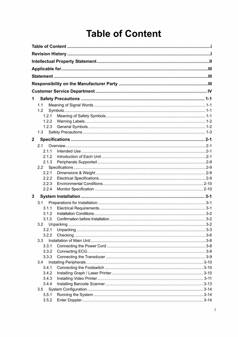
Table of Content Table of Content .....................................................................................................................i Revision History .....................................................................................................................I Intellectual Property Statement ............................................................................................II Applicable for ........................................................................................................................III Statement ..............................................................................................................................III Responsibility on the Manufacturer Party .........................................................................III Customer Service Department ........................................................................................... IV
1 Safety Precautions ..................................................................................................... 1-1
1.1 Meaning of Signal Words ..................................................................................................... 1-1
1.2 Symbols ................................................................................................................................ 1-1
1.2.1 Meaning of Safety Symbols .......................................................................................... 1-1
1.2.2 Warning Labels ............................................................................................................. 1-2
1.2.3 General Symbols .......................................................................................................... 1-2
1.3 Safety Precautions ............................................................................................................... 1-3
2 Specifications ............................................................................................................. 2-1
2.1 Overview .............................................................................................................................. 2-1
2.1.1 Intended Use ................................................................................................................ 2-1
2.1.2 Introduction of Each Unit .............................................................................................. 2-1
2.1.3 Peripherals Supported .................................................................................................. 2-9
2.2 Specifications ....................................................................................................................... 2-9
2.2.1 Dimensions & Weight ................................................................................................... 2-9
2.2.2 Electrical Specifications ................................................................................................ 2-9
2.2.3 Environmental Conditions ........................................................................................... 2-10
2.2.4 Monitor Specification .................................................................................................. 2-10
3 System Installation ..................................................................................................... 3-1
3.1 Preparations for Installation.................................................................................................. 3-1
3.1.1 Electrical Requirements ................................................................................................ 3-1
3.1.2 Installation Conditions ..................................................................................................... 3-2
3.1.3 Confirmation before Installation ....................................................................................... 3-2
3.2 Unpacking ............................................................................................................................ 3-2
3.2.1 Unpacking ..................................................................................................................... 3-3
3.2.2 Checking ....................................................................................................................... 3-6
3.3 Installation of Main Unit ........................................................................................................ 3-8
3.3.1 Connecting the Power Cord ......................................................................................... 3-8
3.3.2 Connecting ECG ........................................................................................................... 3-9
3.3.3 Connecting the Transducer .......................................................................................... 3-9
3.4 Installing Peripherals .......................................................................................................... 3-10
3.4.1 Connecting the Footswitch ......................................................................................... 3-10
3.4.2 Installing Graph / Laser Printer ................................................................................... 3-10
3.4.3 Installing Video Printer ................................................................................................ 3-11
3.4.4 Installing Barcode Scanner ......................................................................................... 3-13
3.5 System Configuration ......................................................................................................... 3-14
3.5.1 Running the System ................................................................................................... 3-14
3.5.2 Enter Doppler .............................................................................................................. 3-14
ii
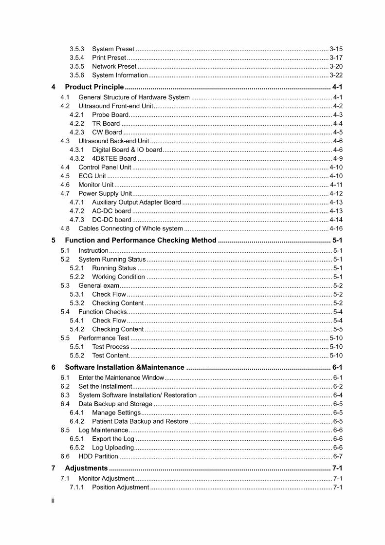
3.5.3 System Preset ............................................................................................................ 3-15
3.5.4 Print Preset ................................................................................................................. 3-17
3.5.5 Network Preset ........................................................................................................... 3-20
3.5.6 System Information ..................................................................................................... 3-22
4 Product Principle ........................................................................................................ 4-1
4.1 General Structure of Hardware System ............................................................................... 4-1
4.2 Ultrasound Front-end Unit .................................................................................................... 4-2
4.2.1 Probe Board .................................................................................................................. 4-3
4.2.2 TR Board ...................................................................................................................... 4-4
4.2.3 CW Board ..................................................................................................................... 4-5
4.3 Ultrasound Back-end Unit ...................................................................................................... 4-6
4.3.1 Digital Board & IO board ............................................................................................... 4-6
4.3.2 4D&TEE Board ............................................................................................................. 4-9
4.4 Control Panel Unit .............................................................................................................. 4-10
4.5 ECG Unit ............................................................................................................................ 4-10
4.6 Monitor Unit ........................................................................................................................ 4-11
4.7 Power Supply Unit .............................................................................................................. 4-12
4.7.1 Auxiliary Output Adapter Board .................................................................................. 4-13
4.7.2 AC-DC board .............................................................................................................. 4-13
4.7.3 DC-DC board .............................................................................................................. 4-14
4.8 Cables Connecting of Whole system ................................................................................. 4-16
5 Function and Performance Checking Method ......................................................... 5-1
5.1 Instruction ............................................................................................................................. 5-1
5.2 System Running Status ........................................................................................................ 5-1
5.2.1 Running Status ............................................................................................................. 5-1
5.2.2 Working Condition ........................................................................................................ 5-1
5.3 General exam ....................................................................................................................... 5-2
5.3.1 Check Flow ................................................................................................................... 5-2
5.3.2 Checking Content ......................................................................................................... 5-2
5.4 Function Checks ................................................................................................................... 5-4
5.4.1 Check Flow ................................................................................................................... 5-4
5.4.2 Checking Content ......................................................................................................... 5-5
5.5 Performance Test ............................................................................................................... 5-10
5.5.1 Test Process ............................................................................................................... 5-10
5.5.2 Test Content ................................................................................................................ 5-10
6 Software Installation &Maintenance ......................................................................... 6-1
6.1 Enter the Maintenance Window .............................................................................................. 6-1
6.2 Set the Installment ................................................................................................................ 6-2
6.3 System Software Installation/ Restoration ........................................................................... 6-4
6.4 Data Backup and Storage .................................................................................................... 6-5
6.4.1 Manage Settings ........................................................................................................... 6-5
6.4.2 Patient Data Backup and Restore ................................................................................ 6-5
6.5 Log Maintenance .................................................................................................................. 6-6
6.5.1 Export the Log .............................................................................................................. 6-6
6.5.2 Log Uploading ............................................................................................................... 6-6
6.6 HDD Partition ....................................................................................................................... 6-7
7 Adjustments ................................................................................................................ 7-1
7.1 Monitor Adjustment............................................................................................................... 7-1
7.1.1 Position Adjustment ...................................................................................................... 7-1
iii
7.1.2 Brightness and Contrast Adjustment ............................................................................ 7-1
7.1.3 Monitor Test .................................................................................................................. 7-2
7.2 Control Panel Adjustment ..................................................................................................... 7-4
7.2.1 Control Panel Position Adjustment ............................................................................... 7-4
7.2.2 Key backlit brightness adjustment ................................................................................ 7-4
7.3 Caster Adjustment ................................................................................................................ 7-4
8 Field Replaceable Unit ............................................................................................... 8-1
9 Structure and Assembly/Disassembly ...................................................................... 9-1
9.1 Structure of the Whole System ............................................................................................. 9-1
9.2 Preparation ........................................................................................................................... 9-3
9.2.1 Tools Required .............................................................................................................. 9-3
9.2.2 Requirement for Engineers ........................................................................................... 9-3
9.2.3 Assembly/Disassembly Requirements ......................................................................... 9-3
9.3 Assembly and Disassembly ................................................................................................. 9-4
9.3.1 Monitor Assembly ......................................................................................................... 9-4
9.3.2 Support Arm Assembly ................................................................................................. 9-7
9.3.3 Probe Board Assembly ................................................................................................. 9-7
9.3.4 ECG Assembly .............................................................................................................. 9-9
9.3.5 Inlet Fan ...................................................................................................................... 9-10
9.3.6 Li-ion Battery ............................................................................................................... 9-11
9.3.7 IO Board/WIFI Board .................................................................................................. 9-11
9.3.8 Hard disk ..................................................................................................................... 9-13
9.3.9 Power Input Assembly ................................................................................................ 9-14
9.3.10 TR board / CW board ................................................................................................. 9-15
9.3.11 Digital Board and CPU Module Assembly .................................................................. 9-16
9.3.12 DC-DC Board Assembly ............................................................................................. 9-17
9.3.13 AC-DC Module ............................................................................................................ 9-18
9.3.14 Outlet Fan ................................................................................................................... 9-20
9.3.15 Motherboard ............................................................................................................... 9-21
9.3.16 Control Panel Assembly ............................................................................................. 9-23
9.3.17 DVD-R/W .................................................................................................................... 9-27
9.3.18 Speaker\ Speaker Cover Assembly ............................................................................ 9-28
9.3.19 Intra-cavity Probe Bracket and Adapter Part ................................................................ 9-28
9.3.20 Salver B and S ............................................................................................................ 9-29
9.3.21 Casters ....................................................................................................................... 9-30
10 Optional Installation/Assembly ............................................................................... 10-1
10.1 Installing Optional Software ................................................................................................ 10-1
10.2 Installing Optional Hardware .............................................................................................. 10-3
10.2.1 ECG Assembly ............................................................................................................ 10-4
10.2.2 Pencil Probe Cable ..................................................................................................... 10-6
10.2.3 CW Board ................................................................................................................... 10-8
10.2.4 Li-ion Battery ............................................................................................................... 10-9
10.2.5 Intra-cavity Probe Bracket ......................................................................................... 10-10
10.2.6 Build-in W-LAN Adapter ............................................................................................ 10-10
10.2.7 4D Update Package.................................................................................................. 10-14
11 System Diagnosis and Support ................................................................................11-1
11.1 General Status Indicator ..................................................................................................... 11-1
11.1.1 The Status Indicators of the Control Panel ................................................................. 11-1
11.1.2 The Status Indicator of the Power on the IO Board .................................................... 11-2

iv
11.1.3 The Status of Whole Machine ..................................................................................... 11-2
11.2 Whole System Start-up Process ........................................................................................ 11-3
11.2.1 Complete System Start-up Process ............................................................................ 11-4
11.2.2 BIOS Start-up Process................................................................................................ 11-5
11.2.3 Linux Start-up Process ............................................................................................... 11-5
11.2.4 Doppler Start-up Process ........................................................................................... 11-5
11.3 Warning and Abnormal Information .................................................................................... 11-8
11.3.1 Battery Alarm .............................................................................................................. 11-8
11.3.2 The Voltage of System Power Alarm .......................................................................... 11-9
11.3.3 Temperature Alarm ..................................................................................................... 11-9
11.3.4 Fan Alarm ................................................................................................................. 11-10
11.3.5 PHV Alarm ................................................................................................................ 11-10
11.3.6 Other Alarms .............................................................................................................. 11-11
12 Care & Maintenance ................................................................................................. 12-1
12.1 Overview ............................................................................................................................ 12-1
12.1.1 Tools, Measurement Devices and Consumables ....................................................... 12-1
12.1.2 Care and Maintenance Items ..................................................................................... 12-1
12.2 Cleaning ............................................................................................................................. 12-3
12.2.1 Clean the System ....................................................................................................... 12-3
12.2.2 Clean the Peripherals ................................................................................................. 12-6
12.3 Checking ............................................................................................................................ 12-7
12.3.1 General check ............................................................................................................. 12-7
12.3.2 System Function Check .............................................................................................. 12-7
12.3.3 Peripherals and Options Check .................................................................................. 12-8
12.3.4 Mechanical Safety Inspection ..................................................................................... 12-8
12.3.5 Electrical Safety Inspection ...................................................................................... 12-10
13 Troubleshooting of Regular Malfunctions .............................................................. 13-1
13.1 Troubleshooting When System Can’t Be Powered on ....................................................... 13-1
13.1.1 Module or Board Related ............................................................................................ 13-1
13.1.2 Key Points Supporting Troubleshooting ..................................................................... 13-1
13.1.3 Troubleshooting When System Can’t Be Powered on ............................................... 13-1
13.2 Troubleshooting When System cannot be started up ........................................................ 13-2
13.2.1 Module or Board Related ............................................................................................ 13-2
13.2.2 Key Points Supporting Troubleshooting ..................................................................... 13-2
13.2.3 Troubleshooting When System cannot be Started ..................................................... 13-2
13.3 Troubleshooting for Image Displaying ................................................................................ 13-3
13.3.1 Module or Board Related ............................................................................................ 13-3
13.3.2 Key Points Supporting Troubleshooting ..................................................................... 13-4
13.3.3 Troubleshooting for Image Displaying ........................................................................ 13-4
13.4 Probe Socket System Related Malfunction Troubleshooting ............................................. 13-5
13.4.1 Module or Board Related ............................................................................................ 13-5
13.4.2 Key Points Supporting Troubleshooting ..................................................................... 13-5
13.4.3 Probe Socket System Related Malfunction Troubleshooting ..................................... 13-5
13.5 IO System Related Malfunction Troubleshooting ............................................................... 13-6
13.5.1 Module or Board Related ............................................................................................ 13-6
13.5.2 Key Points Supporting Troubleshooting ..................................................................... 13-6
13.5.3 IO System Related Malfunction Troubleshooting ....................................................... 13-6
13.6 Control Panel Malfunction Troubleshooting ....................................................................... 13-7
13.6.1 Module or Board Related ............................................................................................ 13-7
13.6.2 Key Points Supporting Troubleshooting ..................................................................... 13-8

v
13.6.3 Control Panel Malfunction Troubleshooting ................................................................ 13-8
13.7 LCD and Display Malfunction Troubleshooting .................................................................. 13-9
13.7.1 Module or Board Related ............................................................................................ 13-9
13.7.2 Key Points Supporting Troubleshooting ..................................................................... 13-9
13.7.3 Display Related Troubleshooting ................................................................................ 13-9
13.8 ECG Module Related Troubleshooting............................................................................. 13-10
13.8.1 Module or Board Related .......................................................................................... 13-10
13.8.2 Key Points Supporting Troubleshooting ................................................................... 13-10
13.8.3 ECG module Related Troubleshooting ..................................................................... 13-10
Appendix A Electrical Safety Inspection .................................................................. A-1
Appendix B Phantom Usage Illustration ................................................................... B-1
Appendix C Requirements of Performance Indices ................................................ C-1

I
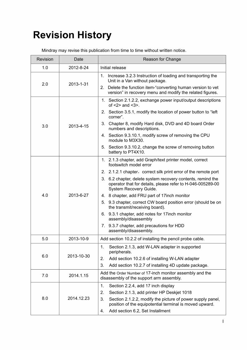
Revision History Mindray may revise this publication from time to time without written notice.
Revision Date Reason for Change
1.0 2012-8-24 Initial release
2.0 2013-1-31
1. Increase 3.2.3 Instruction of loading and transporting the Unit in a Van without package.
2. Delete the function item-“converting human version to vet version” in recovery menu and modify the related figures.
3.0 2013-4-15
1. Section 2.1.2.2, exchange power input/output descriptions of <2> and <3>.
2. Section 3.5.1, modify the location of power button to “left corner”.
3. Chapter 8, modify Hard disk, DVD and 4D board Order numbers and descriptions.
4. Section 9.3.10.1, modify screw of removing the CPU module to M3X30.
5. Section 9.3.10.2, change the screw of removing button battery to PT4X10.
4.0 2013-6-27
1. 2.1.3 chapter, add Graph/text printer model, correct footswitch model error
2. 2.1.2.1 chapter,correct silk print error of the remote port 3. 6.2 chapter, delete system recovery contents, remind the
operator that for details, please refer to H-046-005289-00 System Recovery Guide.
4. 8 chapter, add FRU part of 17inch monitor 5. 9.3 chapter, correct CW board position error (should be on
the transmit/receiving board). 6. 9.3.1 chapter, add notes for 17inch monitor
assembly/disassembly 7. 9.3.7 chapter, add precautions for HDD
assembly/disassembly.
5.0 2013-10-9 Add section 10.2.2 of installing the pencil probe cable.
6.0 2013-10-30
1. Section 2.1.3, add W-LAN adapter in supported peripherals.
2. Add section 10.2.6 of installing W-LAN adapter 3. Add section 10.2.7 of installing 4D update package.
7.0 2014.1.15 Add the Order Number of 17-inch monitor assembly and the disassembly of the support arm assembly.
8.0 2014.12.23
1. Section 2.2.4, add 17 inch display 2. Section 2.1.3, add printer HP Deskjet 1018 3. Section 2.1.2.2, modify the picture of power supply panel,
position of the equipotential terminal is moved upward. 4. Add section 6.2, Set Installment
II
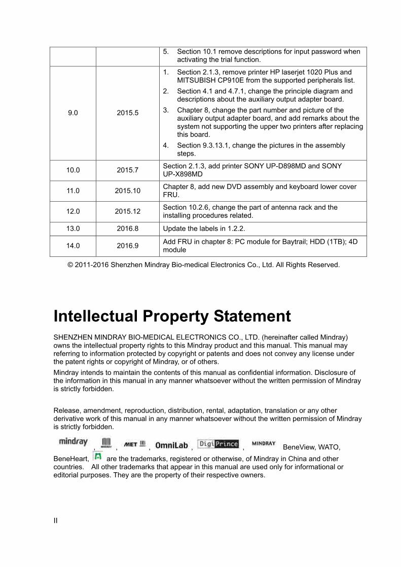
5. Section 10.1 remove descriptions for input password when activating the trial function.
9.0 2015.5
1. Section 2.1.3, remove printer HP laserjet 1020 Plus and MITSUBISH CP910E from the supported peripherals list.
2. Section 4.1 and 4.7.1, change the principle diagram and descriptions about the auxiliary output adapter board.
3. Chapter 8, change the part number and picture of the auxiliary output adapter board, and add remarks about the system not supporting the upper two printers after replacing this board.
4. Section 9.3.13.1, change the pictures in the assembly steps.
10.0 2015.7 Section 2.1.3, add printer SONY UP-D898MD and SONY UP-X898MD
11.0 2015.10 Chapter 8, add new DVD assembly and keyboard lower cover FRU.
12.0 2015.12 Section 10.2.6, change the part of antenna rack and the installing procedures related.
13.0 2016.8 Update the labels in 1.2.2.
14.0 2016.9 Add FRU in chapter 8: PC module for Baytrail; HDD (1TB); 4D module
© 2011-2016 Shenzhen Mindray Bio-medical Electronics Co., Ltd. All Rights Reserved.
Intellectual Property Statement SHENZHEN MINDRAY BIO-MEDICAL ELECTRONICS CO., LTD. (hereinafter called Mindray) owns the intellectual property rights to this Mindray product and this manual. This manual may referring to information protected by copyright or patents and does not convey any license under the patent rights or copyright of Mindray, or of others. Mindray intends to maintain the contents of this manual as confidential information. Disclosure of the information in this manual in any manner whatsoever without the written permission of Mindray is strictly forbidden. Release, amendment, reproduction, distribution, rental, adaptation, translation or any other derivative work of this manual in any manner whatsoever without the written permission of Mindray is strictly forbidden.
, , , , , BeneView, WATO, BeneHeart, are the trademarks, registered or otherwise, of Mindray in China and other countries. All other trademarks that appear in this manual are used only for informational or editorial purposes. They are the property of their respective owners.

III
Applicable for This service manual is applicable for the service engineers, authorized service personnel and service representatives of this ultrasound system.
Statement This service manual describes the product according to the most complete configuration; some of the content may not apply to the product you are responsible for. If you have any questions, please contact Mindray Customer Service Department. Do not attempt to service this equipment unless this service manual has been consulted and is understood. Failure to do so may result in personnel injury or product damage.
Responsibility on the Manufacturer Party Mindray is responsible for the effects on safety, reliability and performance of this product, only if:
All installation operations, expansions, changes, modifications and repairs of this product are
conducted by Mindray authorized personnel;
The electrical installation of the relevant room complies with the applicable national and local
requirements;
The product is used in accordance with the instructions for use.
Mindray's obligation or liability under this warranty does not include any transportation or other charges or liability for direct, indirect or consequential damages or delay resulting from the improper use or application of the product or the use of parts or accessories not approved by Mindray or repairs by people other than Mindray authorized personnel. This warranty shall not extend to:
Any Mindray product which has been subjected to misuse, negligence or accident;
Any Mindray product from which Mindray's original serial number tag or product identification
markings have been altered or removed;
Any products of any other manufacturers.
WARNING: It is important for the hospital or organization that employs this equipment to carry out a reasonable service/maintenance plan. Neglect of this may result in machine breakdown or injury of human health.
IV
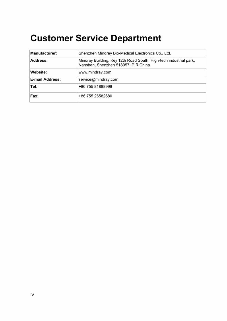
Customer Service Department
Manufacturer: Shenzhen Mindray Bio-Medical Electronics Co., Ltd.
Address: Mindray Building, Keji 12th Road South, High-tech industrial park, Nanshan, Shenzhen 518057, P.R.China
Website: www.mindray.com
E-mail Address: [email protected]
Tel: +86 755 81888998
Fax: +86 755 26582680
Safety precautions1-1
1 Safety Precautions
This chapter describes important issues related to safety precautions, as well as the labels and icons on the ultrasound machine.
1.1 Meaning of Signal Words In this operator’s manual, the signal words DANGER, WARNING, CAUTION and
NOTE are used regarding safety and other important instructions. The signal words and their meanings are defined as follows. Please understand their meanings clearly before reading this manual.
Signal word Meaning
DANGER Indicates an imminently hazardous situation that, if not avoided, will result in death or serious injury.
WARNING Indicates a potentially hazardous situation that, if not avoided, could result in death or serious injury.
CAUTION Indicates a potentially hazardous situation that, if not avoided, may result in minor or moderate injury.
NOTE Indicates a potentially hazardous situation that, if not avoided, may result in property damage.
1.2 Symbols The following tables provide location and information of the safety symbols and warning labels,
please read carefully.
1.2.1 Meaning of Safety Symbols
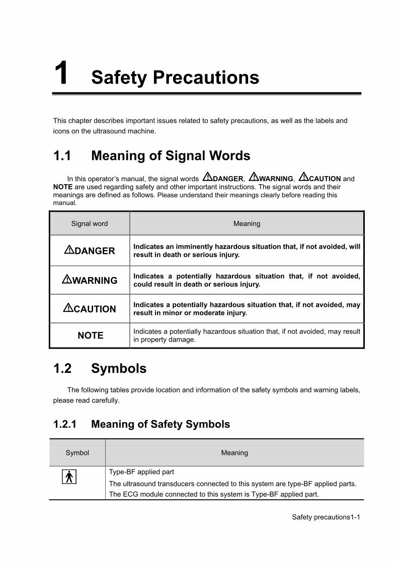
Symbol Meaning
Type-BF applied part
The ultrasound transducers connected to this system are type-BF applied parts. The ECG module connected to this system is Type-BF applied part.
1-2 Safety precautions
Caution.
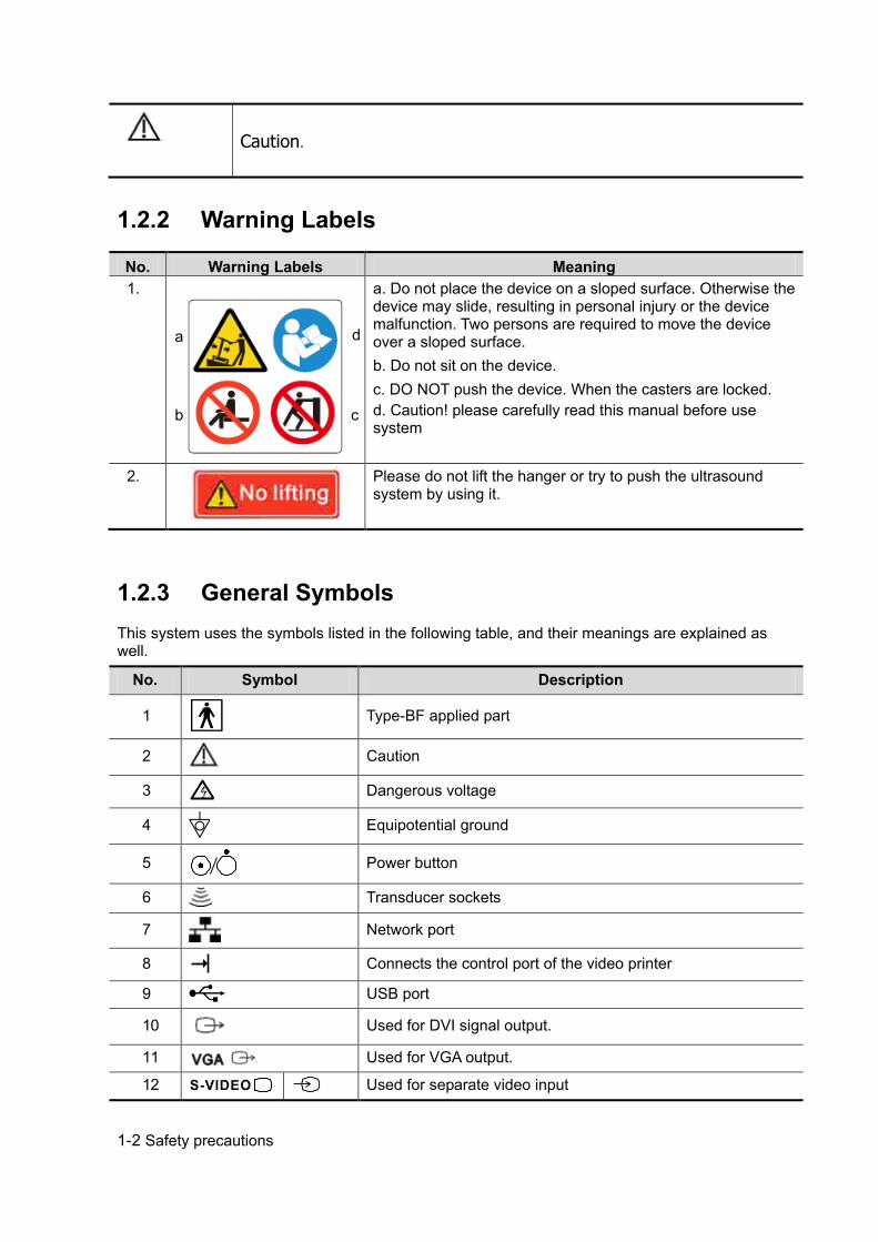
1.2.2 Warning Labels
No. Warning Labels Meaning 1.
a. Do not place the device on a sloped surface. Otherwise the device may slide, resulting in personal injury or the device malfunction. Two persons are required to move the device over a sloped surface. b. Do not sit on the device. c. DO NOT push the device. When the casters are locked. d. Caution! please carefully read this manual before use system
2.
Please do not lift the hanger or try to push the ultrasound system by using it.
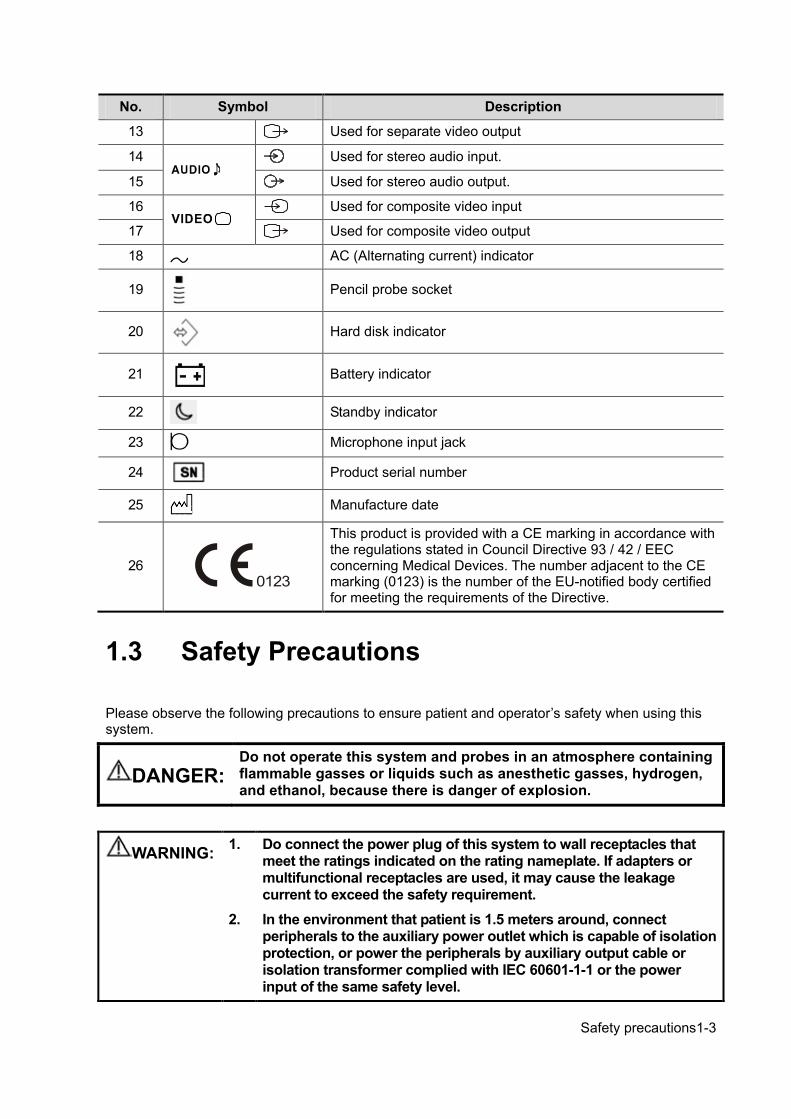
1.2.3 General Symbols This system uses the symbols listed in the following table, and their meanings are explained as well.
No. Symbol Description
1
Type-BF applied part
2 Caution
3
Dangerous voltage
4 Equipotential ground
5 Power button
6 Transducer sockets
7 Network port
8 Connects the control port of the video printer
9 USB port
10 Used for DVI signal output.
11 Used for VGA output.
12 Used for separate video input
a
b c
d
Safety precautions1-3
No. Symbol Description
13 Used for separate video output
14
Used for stereo audio input.
15 Used for stereo audio output.
16
Used for composite video input
17 Used for composite video output
18 AC (Alternating current) indicator
19
Pencil probe socket
20
Hard disk indicator
21
Battery indicator
22 Standby indicator
23 Microphone input jack
24 Product serial number
25 Manufacture date
26
This product is provided with a CE marking in accordance with the regulations stated in Council Directive 93 / 42 / EEC concerning Medical Devices. The number adjacent to the CE marking (0123) is the number of the EU-notified body certified for meeting the requirements of the Directive.
1.3 Safety Precautions Please observe the following precautions to ensure patient and operator’s safety when using this system.
DANGER: Do not operate this system and probes in an atmosphere containing flammable gasses or liquids such as anesthetic gasses, hydrogen, and ethanol, because there is danger of explosion.
WARNING: 1. Do connect the power plug of this system to wall receptacles that meet the ratings indicated on the rating nameplate. If adapters or multifunctional receptacles are used, it may cause the leakage current to exceed the safety requirement.
2. In the environment that patient is 1.5 meters around, connect peripherals to the auxiliary power outlet which is capable of isolation protection, or power the peripherals by auxiliary output cable or isolation transformer complied with IEC 60601-1-1 or the power input of the same safety level.
1-4 Safety precautions
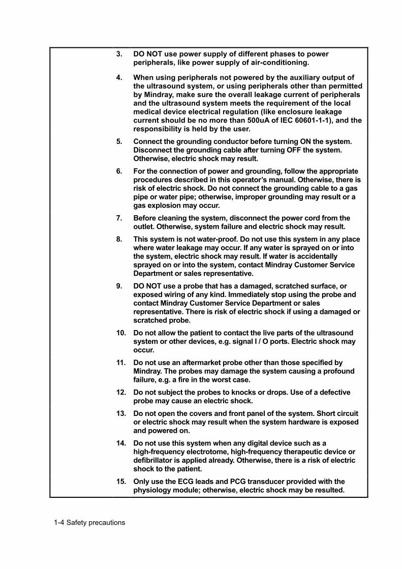
3. DO NOT use power supply of different phases to power peripherals, like power supply of air-conditioning.
4. When using peripherals not powered by the auxiliary output of the ultrasound system, or using peripherals other than permitted by Mindray, make sure the overall leakage current of peripherals and the ultrasound system meets the requirement of the local medical device electrical regulation (like enclosure leakage current should be no more than 500uA of IEC 60601-1-1), and the responsibility is held by the user.
5. Connect the grounding conductor before turning ON the system. Disconnect the grounding cable after turning OFF the system. Otherwise, electric shock may result.
6. For the connection of power and grounding, follow the appropriate procedures described in this operator’s manual. Otherwise, there is risk of electric shock. Do not connect the grounding cable to a gas pipe or water pipe; otherwise, improper grounding may result or a gas explosion may occur.
7. Before cleaning the system, disconnect the power cord from the outlet. Otherwise, system failure and electric shock may result.
8. This system is not water-proof. Do not use this system in any place where water leakage may occur. If any water is sprayed on or into the system, electric shock may result. If water is accidentally sprayed on or into the system, contact Mindray Customer Service Department or sales representative.
9. DO NOT use a probe that has a damaged, scratched surface, or exposed wiring of any kind. Immediately stop using the probe and contact Mindray Customer Service Department or sales representative. There is risk of electric shock if using a damaged or scratched probe.
10. Do not allow the patient to contact the live parts of the ultrasound system or other devices, e.g. signal I / O ports. Electric shock may occur.
11. Do not use an aftermarket probe other than those specified by Mindray. The probes may damage the system causing a profound failure, e.g. a fire in the worst case.
12. Do not subject the probes to knocks or drops. Use of a defective probe may cause an electric shock.
13. Do not open the covers and front panel of the system. Short circuit or electric shock may result when the system hardware is exposed and powered on.
14. Do not use this system when any digital device such as a high-frequency electrotome, high-frequency therapeutic device or defibrillator is applied already. Otherwise, there is a risk of electric shock to the patient.
15. Only use the ECG leads and PCG transducer provided with the physiology module; otherwise, electric shock may be resulted.

Safety precautions1-5
16. When moving the system, you should hold the handle; otherwise, damage may be resulted by abnormal force. Do not push the system from the left/right side; otherwise, it may be toppled over.
17. The auxiliary power output outlet in the system is used to supply power for the recommended peripheral devices. Do not connect other devices to the outlet, otherwise, the rated output power may be exceeded and failure may be resulted. Maximum output power of the outlet is 240VA.
18. Accessory equipment (analog or digital) connected to the ultrasound system must comply with the relevant IEC standards (e.g., IEC 60950 information technology equipment safety standard and IEC 60601-1 medical equipment standard).Furthermore, all configurations must comply with the standard IEC 60601-1-1.It is the responsibility of the person, who connects additional equipment to the signal input or output ports and configures a medical system, to verify that the system complies with the requirements of IEC 60601-1-1.If you have any questions regarding these requirements, consult your sales representative.
19. Prolonged and repeated use of keyboards may result in hand or arm nerve disorders for some individuals. Observe the local safety or health regulations concerning the use of keyboards.
20. When using intra-cavity probes, do not activate the probe outside the patient’s body.
21. DO NOT touch the Signal I/O ports if in contact with the patient; otherwise patient injury may result.
1-6 Safety precautions
CAUTION: 1. Precautions concerning clinical examination techniques: This system must be used only by qualified medical professionals. This operator’s manual does not describe clinical examination techniques. The clinician should select the proper examination techniques based on specialized training and clinical experience.
2. Malfunctions due to radio wave: If a radio wave emitting device is used in the proximity of this system, it may interfere with operations. Do not use or take any devices transmitting RF signals (such as cellular phones, transceivers and radio controlled products) in the room placing the system. If a person brings a device that generates radio waves near the system, ask him / her to immediately turn OFF the device.
3. Precautions concerning movement of the system: Please install the system on a flat plane with casters locked. Otherwise, damage may be resulted by accidental moving. Do not move the system laterally, which may result in damage in case of toppling. Move the system slowly on the slope by two people, otherwise, damage may result in case of unexpected sliding. Do not sit on the system, which may result individual falling in case of system moving. Object placed on the monitor may fall and injure an individual. Fasten and fully secure any peripheral device before moving the system. A loose peripheral device may fall and injure an individual. When move the system on the steps, please take care to prevent the system from toppling.
4. If the circuit protector is tripped, it indicates that the system or a peripheral device was improperly shut down and the system is unstable. You cannot repair the system under this circumstance and must call the Mindray Customer Service Department or sales representative.
5. There is no risk of high-temperature burns during normal ultrasound examinations. It is possible for the surface temperature of the probe to exceed the body temperature of a patient due to environmental temperature and exam type combinations. Do not apply the probe to the same region on the patient for a long time. Apply the probe only for a period of time required for the purpose of diagnosis.
6. Do not use the system to examine a fetus for a long period of time.
7. The system and its accessories are not disinfected or sterilized prior to delivery. The operator is responsible for the cleaning and disinfection of probes and sterilization of biopsy brackets according to the manuals, prior to the use. All items must be thoroughly processed to completely remove harmful residual chemicals, which will not only be harmful to the human body, but also damage the accessory.
Safety precautions1-7
8. It is necessary to press <End Exam> to end the current scan that is in progress and clear the current Patient Information field. Otherwise, new patient data may be combined with the previous patient data.
9. Do not connect or disconnect the system’s power cord or its accessories (e.g., a printer or a recorder) without turning OFF the system power first. This may damage the system and its accessories or cause electric shock.
10. If the system is powered off improperly during operation, it may result in data damage of the system hard disk or system failure.
11. Do not use a USB memory device (e.g., a USB flash drive, removable hard disk) which has unsafe data. Otherwise, system damage may result.
12. It is recommended to only use the video devices specified in this manual.
13. Do not use gel, disinfectant, probes, probe sheath or needle-guided brackets that are not compatible with the system.
14. The applied contrast agents should be compliant with the relevant local regulations.
15. Read the Acoustic Output Principle in the operation manual carefully before operating this system on clinical examination.
16. The cover contains natural rubber that can cause allergic reactions in some individuals.
17. Please use the ultrasound gel compliant with the relevant local regulations.
18. Normal operation may be affected by unstable mains power supply; it is recommended that our product be powered from an uninterruptible power supply.
NOTE: 1. DO NOT use the system in the vicinity of strong electromagnetic field (such as a transformer), which may affect the performance of the system.
2. Do not use the system in the vicinity of high-frequency radiation source (e.g. cellular phones), which may affect the performance of the system or even lead to failure.
3. When using or placing the system, keep the system horizontal to avoid imbalance.
4. To avoid damaging the system, do not use it in following environment: Locations exposed to direct sunlight; Locations subject to sudden changes in environmental temperature; Dusty locations; Locations subject to vibration; Locations near heat generators; Locations with high humidity.
5. Turn ON the system only after the power has been turned OFF for a while. If the system is turned ON immediately after being turned OFF, the system may not be rebooted properly and could malfunction.
6. Press <Freeze> key to freeze an image or turn off the power of the system before connecting or disconnecting a probe. Otherwise, the system and/or probe can be damaged.
1-8 Safety precautions
7. Remove the ultrasound gel from the face of the probe when the examination is completed. Water in the gel may enter the acoustic lens and adversely affect the performance and safety of the probe.
8. You should properly back up the system to a secure external storage media, including system configuration, settings and patient data. Data stored to the system’s hard drive may be lost due to system failure, improper operation or accident.
9. Do not apply external force to the control panel. Otherwise, the system may be damaged.
10. If the system is used in a small room, the room temperature may rise. Please provide proper ventilation and free air exchange.
11. To dispose of the system or any part, contact Mindray Customer Service Department or sales representative. Mindray is not responsible for any system content or accessories that have been discarded improperly. Mindray is not responsible for any system content or accessories that have been discarded improperly.
12. Electrical and mechanical performance may be degraded due to long usage (such as current leakage or distortion and abrasion); the image sensitivity and precision may become worse too. To ensure optimal system operations, it is recommended that you maintain the system under a Mindray service agreement.
13. The replaceable fuse is inside the chassis. Refer replacing job to Mindray service engineers or engineers authorized by Mindray only.
14. Do not turn OFF the power supply of the system during printing, file storage or invoking other system operations. An interrupted process may not be completed, and can become lost or corrupted.
15. The iScape feature constructs a single extended image from a series of individual image frames. The quality of the final image is user-dependent and requires skill to efficiently apply the feature and technique. Exercise caution when measurements are performed from an iScape image.
16. Ensure that the current exam date and time are the same as the system date and time.
Specifications 2-1
2 Specifications
2.1 Overview
2.1.1 Intended Use DC-N3 PRO/DC-N3T/DC-N3S/DC-N3 diagnostic ultrasound system is intended for use in clinical ultrasonic diagnosis.DC-N3 Vet is a type of veterinary use.
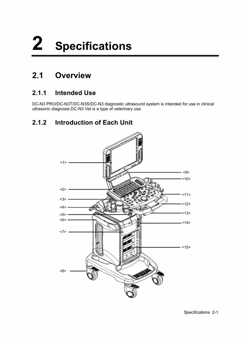
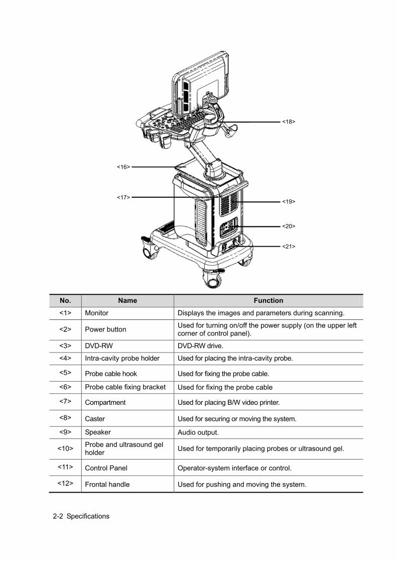
2.1.2 Introduction of Each Unit
<1>
<2>
<3>
<4>
<5><6>
<7>
<8>
<9>
<10>
<11>
<12>
<13>
<14>
<15>
2-2 Specifications
<16>
<17>
<18>
<19>
<20>
<21>
No. Name Function
<1> Monitor Displays the images and parameters during scanning.
<2> Power button Used for turning on/off the power supply (on the upper left corner of control panel).
<3> DVD-RW DVD-RW drive.
<4> Intra-cavity probe holder Used for placing the intra-cavity probe.
<5> Probe cable hook Used for fixing the probe cable.
<6> Probe cable fixing bracket Used for fixing the probe cable
<7> Compartment Used for placing B/W video printer.
<8> Caster Used for securing or moving the system.
<9> Speaker Audio output.
<10> Probe and ultrasound gel holder Used for temporarily placing probes or ultrasound gel.
<11> Control Panel Operator-system interface or control.
<12> Frontal handle Used for pushing and moving the system.
Specifications 2-3
No. Name Function
<13> Control table adjusting
handle
Lift and hold the handle to lift/down the control table, or to
turn the control table left / right.
<14> Physiological-signal panel Used for connecting the ECG leads, footswitch, and
inputting ECG signal.
<15> Probe ports Sockets connecting probes and the main unit.
The lowest one is for 4D probes.
<16> Table for placing
peripherals
Placing peripherals.
<17> Rear handle Used for lifting the machine, or managing the probe cable.
<18> Monitor support arm Used for support and adjustment of height and position of LCD monitor.
<19> Heat rejection panel Main unit heat rejection.
<20> I/O Panel Interface panel used for inputting and outputting signals.
<21> Power supply panel Electrical port panel.
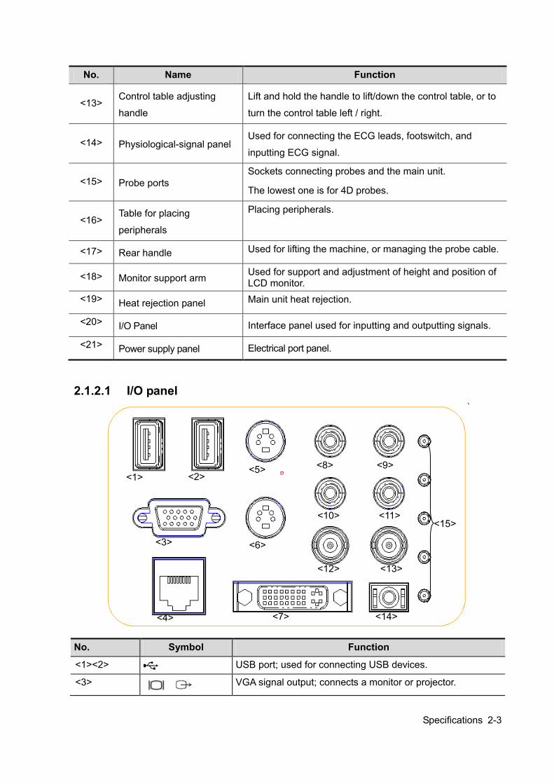
2.1.2.1 I/O panel
No. Symbol Function
<1><2> USB port; used for connecting USB devices.
<3> VGA signal output; connects a monitor or projector.
<1> <2>
<3>
<4>
<5>
<6>
<14> <7>
<8> <9>
<10> <11>
<12> <13>
<15>
2-4 Specifications
<4> Ethernet interface.
<5> Reserved, separate video input.
<6> Separate video output.
<7>
DVI signal output.
<8><9> Audio signal input port, left channel/ right channel.
<10><11> Audio signal output port, left channel/right channel.
<12> Reserved, used for composite video input.
<13> Used for composite video output.
<14> Remote interface for connecting video printer.
<15> Status indication lights
Indicate the voltage and other status of the ultrasound machine (referring to 11.1.2).
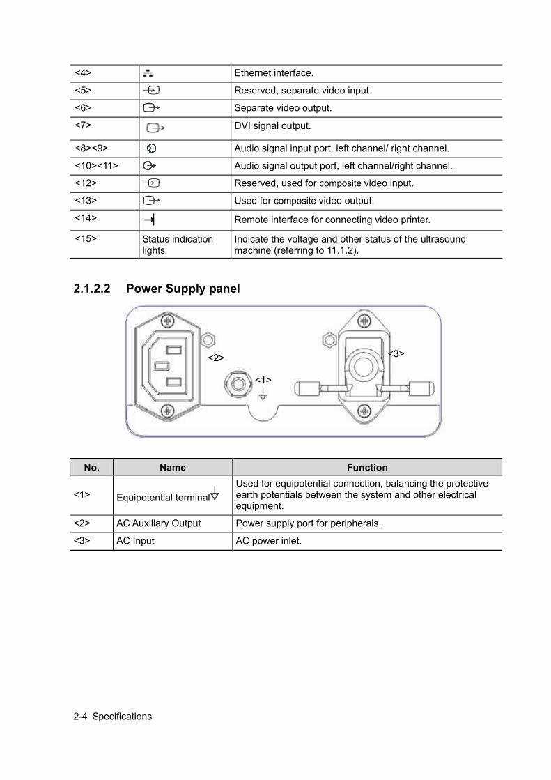
2.1.2.2 Power Supply panel
No. Name Function
<1> Equipotential terminal Used for equipotential connection, balancing the protective earth potentials between the system and other electrical equipment.
<2> AC Auxiliary Output Power supply port for peripherals.
<3> AC Input AC power inlet.
<1>
<2> <3>
Specifications 2-5
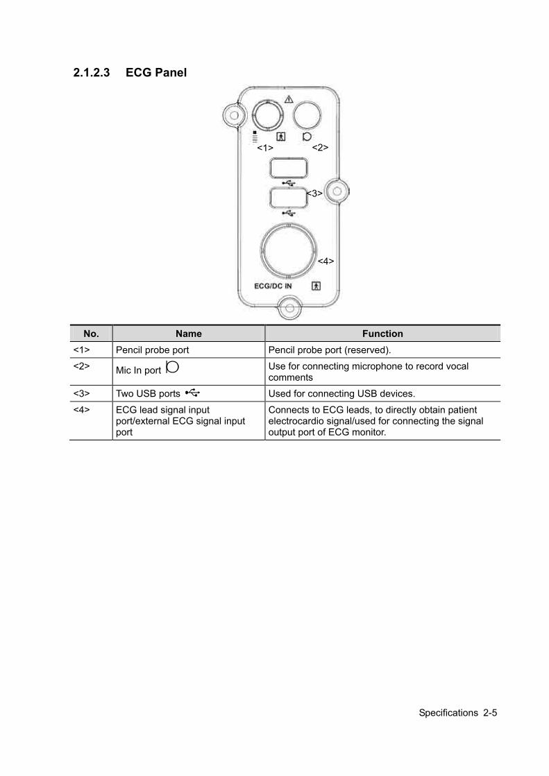
2.1.2.3 ECG Panel
No. Name Function
<1> Pencil probe port Pencil probe port (reserved).
<2> Mic In port Use for connecting microphone to record vocal comments
<3> Two USB ports Used for connecting USB devices.
<4> ECG lead signal input port/external ECG signal input port
Connects to ECG leads, to directly obtain patient electrocardio signal/used for connecting the signal output port of ECG monitor.
<1> <2>
<3>
<4>

2-6 Specifications
2.1.2.4 Control Panel
<1> <2><3><4><5>
<6> <7> <8> <9> <10> <11><12> <13> <14><15><16> <17><18>
<19>
<20>
<21> <22> <23> <24> <25> <26> <27>
<28>
<29>
<30>
<31>
<32>
<33>
<34>
<35>
<37>
<38> <39>
<40>
<41>
<42>
<44><45>
<43>
<46>
<47><48>
<49> <52>
<50> <53>
<51> <54>
<55>
<36>
No. Name Description Function
<1> / Power button Press the button to turn on the system, at the moment the indicator lights on and becomes green and flashes.
<2> /
Battery status indicator.
<3> / AC power supply status indicator
<4> /
Standby status indicator
<5> /
Hard disk status indicator
<6> Esc Exit Press to exit the current status to the previous status.
<7> F1 Help Help Press to open or close the accompanying help documents.
<8> F2 iStation / Press to enter or exit the patient information management system.
<9> F3 Eject / Press to eject the disc.
<10> F4-F6 User-defined You can assign a function to the key.
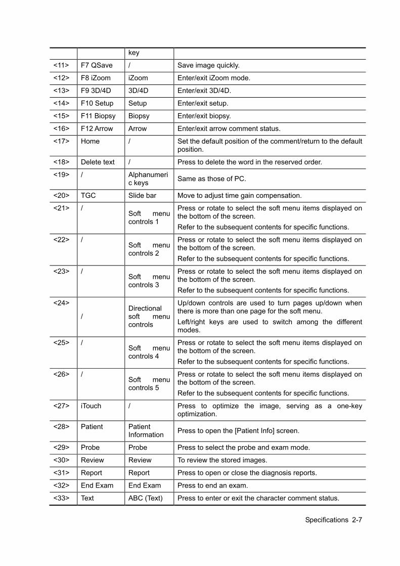
Specifications 2-7
key
<11> F7 QSave / Save image quickly.
<12> F8 iZoom iZoom Enter/exit iZoom mode.
<13> F9 3D/4D 3D/4D Enter/exit 3D/4D.
<14> F10 Setup Setup Enter/exit setup.
<15> F11 Biopsy Biopsy Enter/exit biopsy.
<16> F12 Arrow Arrow Enter/exit arrow comment status.
<17> Home / Set the default position of the comment/return to the default position.
<18> Delete text / Press to delete the word in the reserved order.
<19> / Alphanumeric keys Same as those of PC.
<20> TGC Slide bar Move to adjust time gain compensation.
<21> / Soft menu controls 1
Press or rotate to select the soft menu items displayed on the bottom of the screen. Refer to the subsequent contents for specific functions.
<22> / Soft menu controls 2
Press or rotate to select the soft menu items displayed on the bottom of the screen. Refer to the subsequent contents for specific functions.
<23> / Soft menu controls 3
Press or rotate to select the soft menu items displayed on the bottom of the screen. Refer to the subsequent contents for specific functions.
<24>
/ Directional soft menu controls
Up/down controls are used to turn pages up/down when there is more than one page for the soft menu. Left/right keys are used to switch among the different modes.
<25> / Soft menu controls 4
Press or rotate to select the soft menu items displayed on the bottom of the screen. Refer to the subsequent contents for specific functions.
<26> / Soft menu controls 5
Press or rotate to select the soft menu items displayed on the bottom of the screen. Refer to the subsequent contents for specific functions.
<27> iTouch / Press to optimize the image, serving as a one-key optimization.
<28> Patient Patient Information Press to open the [Patient Info] screen.
<29> Probe Probe Press to select the probe and exam mode.
<30> Review Review To review the stored images.
<31> Report Report Press to open or close the diagnosis reports.
<32> End Exam End Exam Press to end an exam.
<33> Text ABC (Text) Press to enter or exit the character comment status.
2-8 Specifications
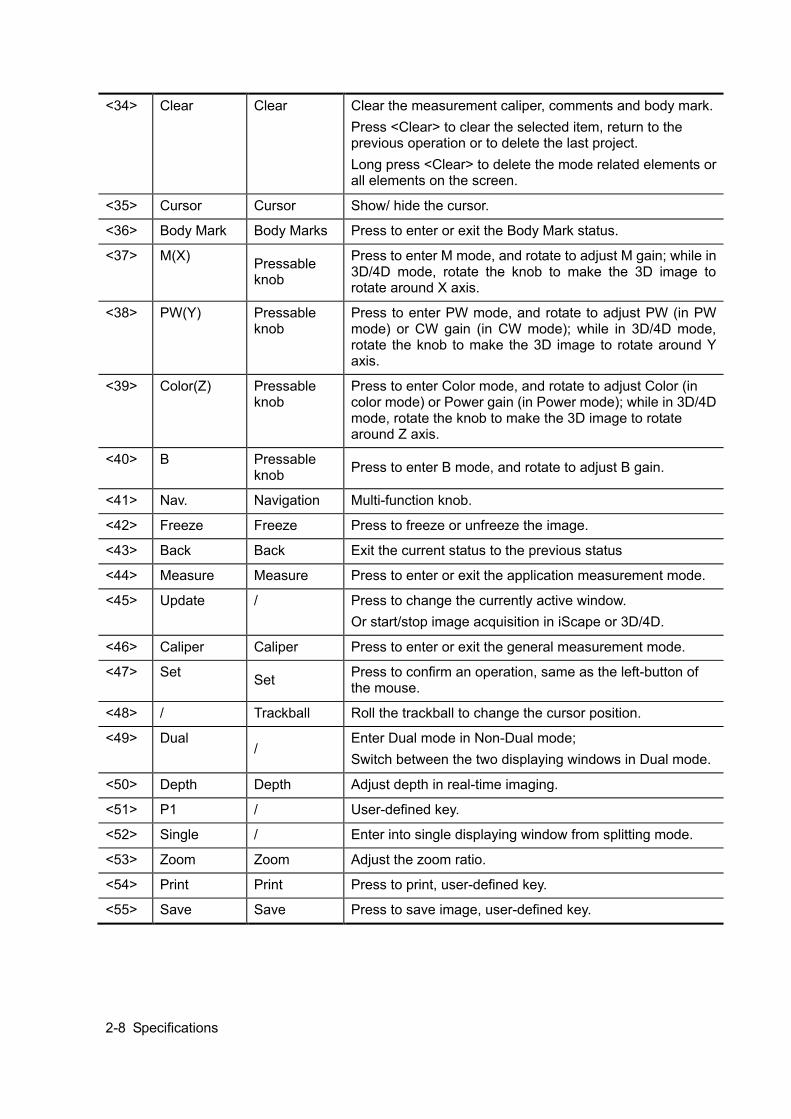
<34> Clear Clear Clear the measurement caliper, comments and body mark. Press <Clear> to clear the selected item, return to the previous operation or to delete the last project. Long press <Clear> to delete the mode related elements or all elements on the screen.
<35> Cursor Cursor Show/ hide the cursor.
<36> Body Mark Body Marks Press to enter or exit the Body Mark status.
<37> M(X) Pressable knob
Press to enter M mode, and rotate to adjust M gain; while in 3D/4D mode, rotate the knob to make the 3D image to rotate around X axis.
<38> PW(Y) Pressable knob
Press to enter PW mode, and rotate to adjust PW (in PW mode) or CW gain (in CW mode); while in 3D/4D mode, rotate the knob to make the 3D image to rotate around Y axis.
<39> Color(Z) Pressable knob
Press to enter Color mode, and rotate to adjust Color (in color mode) or Power gain (in Power mode); while in 3D/4D mode, rotate the knob to make the 3D image to rotate around Z axis.
<40> B Pressable knob Press to enter B mode, and rotate to adjust B gain.
<41> Nav. Navigation Multi-function knob.
<42> Freeze Freeze Press to freeze or unfreeze the image.
<43> Back Back Exit the current status to the previous status
<44> Measure Measure Press to enter or exit the application measurement mode.
<45> Update / Press to change the currently active window. Or start/stop image acquisition in iScape or 3D/4D.
<46> Caliper Caliper Press to enter or exit the general measurement mode.
<47> Set Set Press to confirm an operation, same as the left-button of the mouse.
<48> / Trackball Roll the trackball to change the cursor position.
<49> Dual /
Enter Dual mode in Non-Dual mode; Switch between the two displaying windows in Dual mode.
<50> Depth Depth Adjust depth in real-time imaging.
<51> P1 / User-defined key.
<52> Single / Enter into single displaying window from splitting mode.
<53> Zoom Zoom Adjust the zoom ratio.
<54> Print Print Press to print, user-defined key.
<55> Save Save Press to save image, user-defined key.
Specifications 2-9
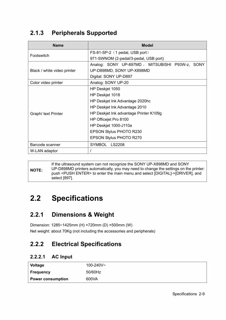
2.1.3 Peripherals Supported
Name Model
Footswitch FS-81-SP-2(1 pedal, USB port) 971-SWNOM (2-pedal/3-pedal, USB port)
Black / white video printer Analog: SONY UP-897MD , MITSUBISHI P93W-z, SONY UP-D898MD, SONY UP-X898MD Digital: SONY UP-D897
Color video printer Analog: SONY UP-20
Graph/ text Printer
HP Deskjet 1050 HP Deskjet 1018 HP Deskjet Ink Advantage 2020hc HP Deskjet Ink Advantage 2010 HP Deskjet Ink advantage Printer K109g HP Officejet Pro 8100 HP Deskjet 1000-J110a EPSON Stylus PHOTO R230 EPSON Stylus PHOTO R270
Barcode scanner SYMBOL LS2208 W-LAN adaptor /
NOTE:
If the ultrasound system can not recognize the SONY UP-X898MD and SONY UP-D898MD printers automatically, you may need to change the settings on the printer: push <PUSH ENTER> to enter the main menu and select [DIGITAL]->[DRIVER], and select [897].
2.2 Specifications
2.2.1 Dimensions & Weight Dimension: 1285~1425mm (H) ×720mm (D) ×500mm (W) Net weight: about 70Kg (not including the accessories and peripherals)
2.2.2 Electrical Specifications
2.2.2.1 AC Input Voltage 100-240V~
Frequency 50/60Hz
Power consumption 600VA
2-10 Specifications
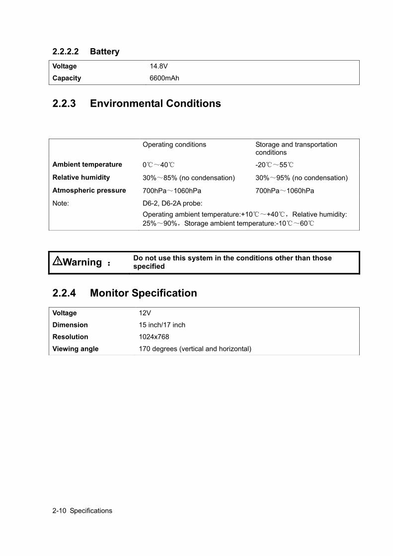
2.2.2.2 Battery
2.2.3 Environmental Conditions
2.2.4 Monitor Specification
Voltage 14.8V
Capacity 6600mAh
Operating conditions Storage and transportation conditions
Ambient temperature 0℃~40℃ -20℃~55℃
Relative humidity 30%~85% (no condensation) 30%~95% (no condensation)
Atmospheric pressure 700hPa~1060hPa 700hPa~1060hPa
Note: D6-2, D6-2A probe: Operating ambient temperature:+10℃~+40℃,Relative humidity: 25%~90%,Storage ambient temperature:-10℃~60℃
Warning : Do not use this system in the conditions other than those specified
Voltage 12V
Dimension 15 inch/17 inch
Resolution 1024x768
Viewing angle 170 degrees (vertical and horizontal)
System Installation 3-1
3 System Installation
3.1 Preparations for Installation NOTE: Do not install the machine in the following locations:
Locations near heat generators;
Locations of high humidity;
Locations with flammable gases.
3.1.1 Electrical Requirements
3.1.1.1 Requirement of Regulated Power Supply Power specification is showing in 2.2.2.Due to the difference of the power supply stability of
different districts, please advise the user to adopt a regulator of good quality and performance such as an on-line UPS.
3.1.1.2 Grounding Requirements The power cable of the system is a three-wire cable, the protective grounding terminal of which
is connected with the grounding phase of the power supply. Please ensure that the grounding protection of the power supply works normally.
WARNING: DO NOT connect this system to outlets with the same circuit breakers and fuses that control the current of devices such as life-support systems. If this system malfunctions and generates an over current, or when there is an instantaneous current at power ON, the circuit breakers and fuses of the building’s supply circuit may be tripped.
3.1.1.3 EMI Limitation Ultrasound machines are susceptible to Electromagnetic Interference (EMI) by radio frequencies, magnetic fields, and transient in the air wiring. They also generate a weak electromagnetic radiation. Possible EMI sources should be identified before the unit is installed. Electrical and electronic equipment may produce EMI unintentionally as the result of defect. These sources include: medical lasers, scanners, monitors, cauterizing guns and so on. Besides, other devices that may result in high frequency electromagnetic interference such as mobile phone, radio transceiver and wireless remote control toys are not allowed to be presented or used in the room. Turn off those devices to make sure the ultrasound system can work in a normal way.

3-2 System Installation
3.1.2 Installation Conditions
3.1.2.1 Space Requirements Place the system with necessary peripherals in a position that is convenient for operation:
1. Place the system in a room with good ventilation or an air conditioner.
2. The door is at least 0.8m wide. The ultrasound machines can move into the room easily.
3. Leave at least 20cm clearance around the system to ensure effective cooling.
4. A adjustable lighting system in the room (dim/bright) is recommended.
5. Except the receptacle dedicated for the ultrasound system, at least 3-4 spare receptacles on
the wall are available for the other medical devices and peripheral devices.
6. Power outlet and place for any external peripheral are within 2 m of each other with peripheral
within 1 m of the unit to connect cables.
3.1.2.2 Networking Pre-installation Requirements Both wireless and wired LAN are supported by this ultrasound system. Data transmission is allowed between different departments or areas without network cable. Network can be automatically connected after disconnection in case that the device is required to be moved, wireless transmission task can be recovered after the network resumed to normal condition. Confirm the network devices and network conditions before the installation.
1. General information: default gateway IP address, and the other routers related information.
2. DICOM application information: DICOM server name, DICOM port, channels, and IP address.
3.1.3 Confirmation before Installation Perform the following confirmation before installing the system: 1. The video format used in the region or country where the system is installed. 2. The language used in the region or country where the system is installed. 3. The power voltage used in the region or country where the system is installed.
4. Obstetric formulae and other measurement formulae used in the region or country where the system is installed.
5. Other settings to be used in the region or country where the system is installed but different from the factory settings.
6. The doctor’s habits of using the system. Perform the confirmation above before installing the system. And set up the system to make it according with the usage of the region or country where the system is installed.
3.2 Unpacking Tool: A scissor or a knife
System Installation 3-3
Installation duration:2 person, 0.5 hour.
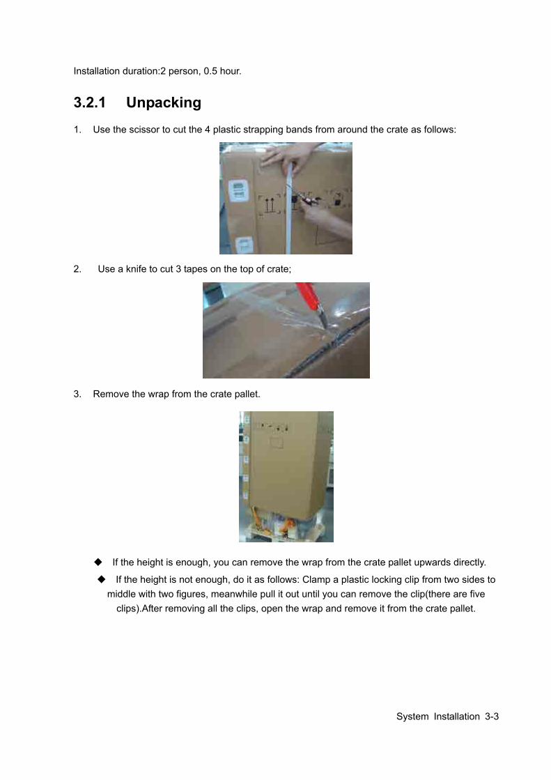
3.2.1 Unpacking 1. Use the scissor to cut the 4 plastic strapping bands from around the crate as follows:
2. Use a knife to cut 3 tapes on the top of crate;
3. Remove the wrap from the crate pallet.
If the height is enough, you can remove the wrap from the crate pallet upwards directly.
If the height is not enough, do it as follows: Clamp a plastic locking clip from two sides to middle with two figures, meanwhile pull it out until you can remove the clip(there are five
clips).After removing all the clips, open the wrap and remove it from the crate pallet.
3-4 System Installation
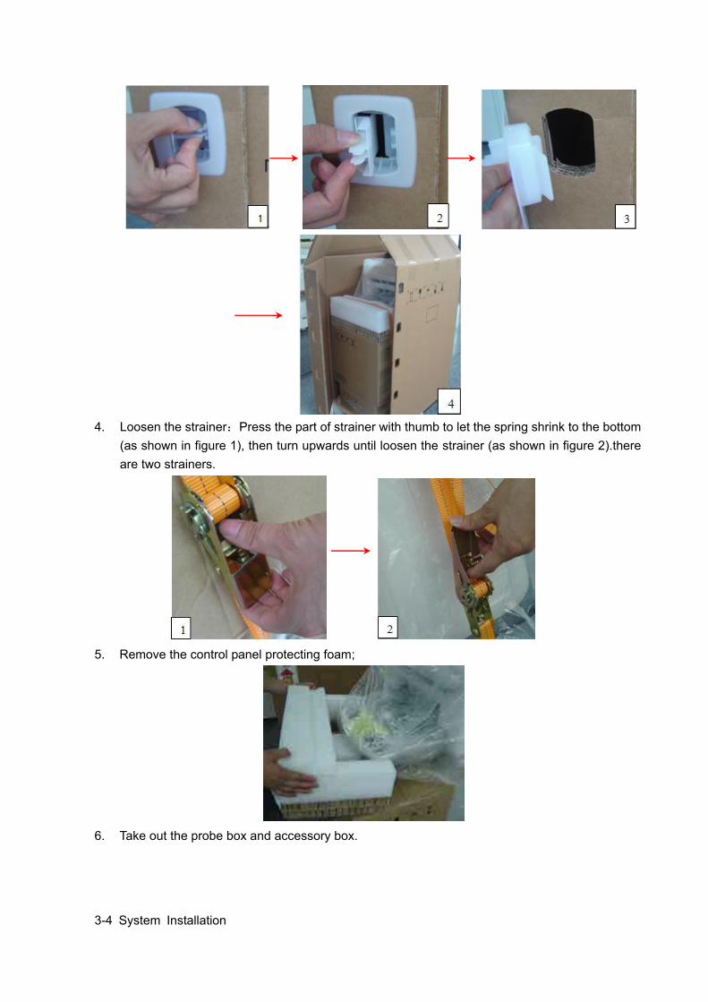
4. Loosen the strainer:Press the part of strainer with thumb to let the spring shrink to the bottom
(as shown in figure 1), then turn upwards until loosen the strainer (as shown in figure 2).there are two strainers.
5. Remove the control panel protecting foam;
6. Take out the probe box and accessory box.
System Installation 3-5
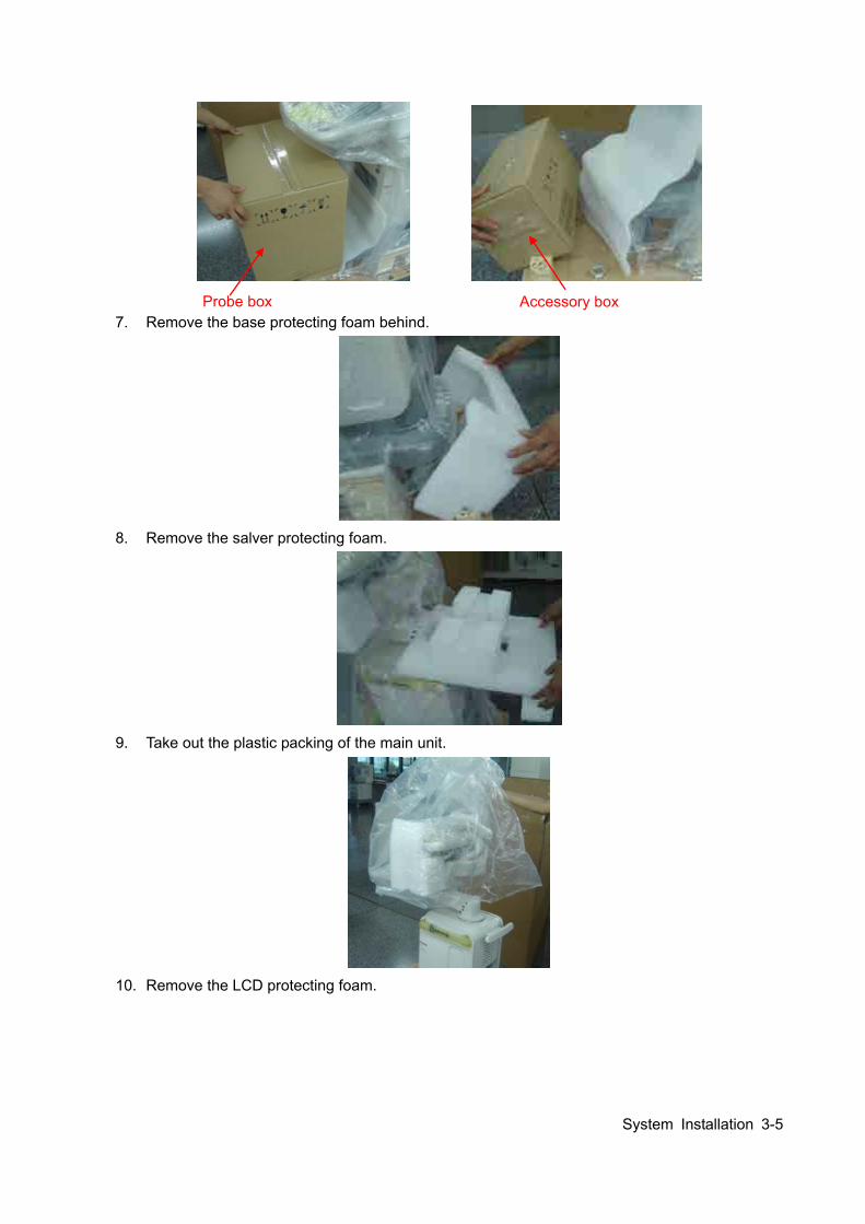
7. Remove the base protecting foam behind.
8. Remove the salver protecting foam.
9. Take out the plastic packing of the main unit.
10. Remove the LCD protecting foam.
Probe box Accessory box
3-6 System Installation
11. Use a knife to cut the tapes attached to the height adjusting handle and loosen it ;
12. Carry the machine off the pallet with another person.
3.2.2 Checking 1. After unpacking, check the objects in the container with the package list to see if anything is in
short supply or is wrong. 2. Inspect and make sure there is no damage to the machine, no indentation, no cracks.
3.2.3 Loading and Transporting the Unit in a Van
3.2.3.1 Overview When moving or transporting the unit without original packing materials, follow the instructions and precautions below to ensure maximum safety for personnel, the system and other equipment. Minimum size for the vehicle door: 700mm (W)*550mm (H) Minimum size for the vehicle capacity (inside):700mm(L)*550mm(W)*1150mm(H)。 Tools necessary: LCD bumper, 1 peace Strap, several
System Installation 3-7
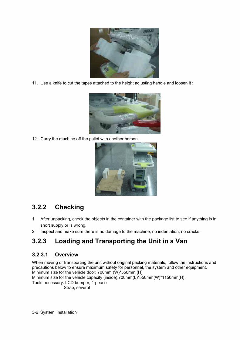
3.2.3.2 Securing the Unit
Figure 1 Securing the Unit
Figure 2 Securing the Unit
Figure 3 Securing the Unit
Use the strap, with one end tied to the front handle, the other end to a proper position of the vehicle.
Install the bumper onto the LCD monitor and the control panel, then strap the bumper together with the LCD monitor and control panel
Install the bumper onto the LCD monitor the control panel as shown in the figure
Tighten the control table adjusting handle with the front handle using a strap
Tighten the front handle with the base using a strap
Put a bumper of 30mm in thickness (or use other soft material), adjust the support arm to anchor it on the bumper
Tighten the base to the proper position of the vehicle using the strap, making sure the unit can’t be moved in any direction.
3-8 System Installation
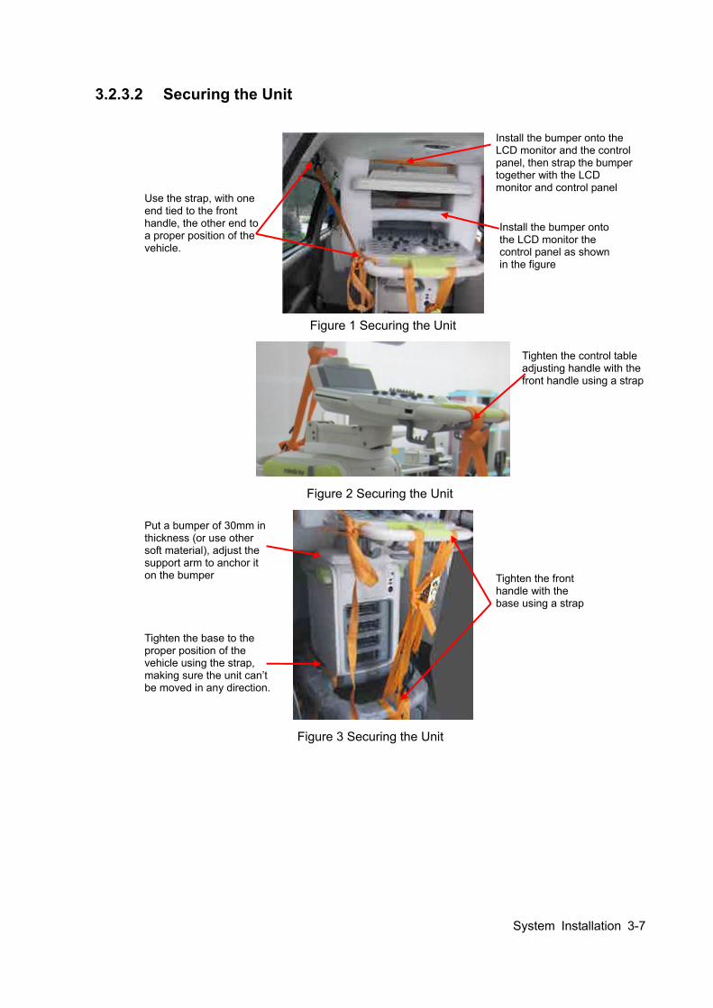
Figure 4 Securing the Unit
Figure 5 Details
Figure 2 Details
3.3 Installation of Main Unit NOTE: To prevent the machine from damage, when you perform the following operations,
please lock the casters if the machine doesn’t to be moved
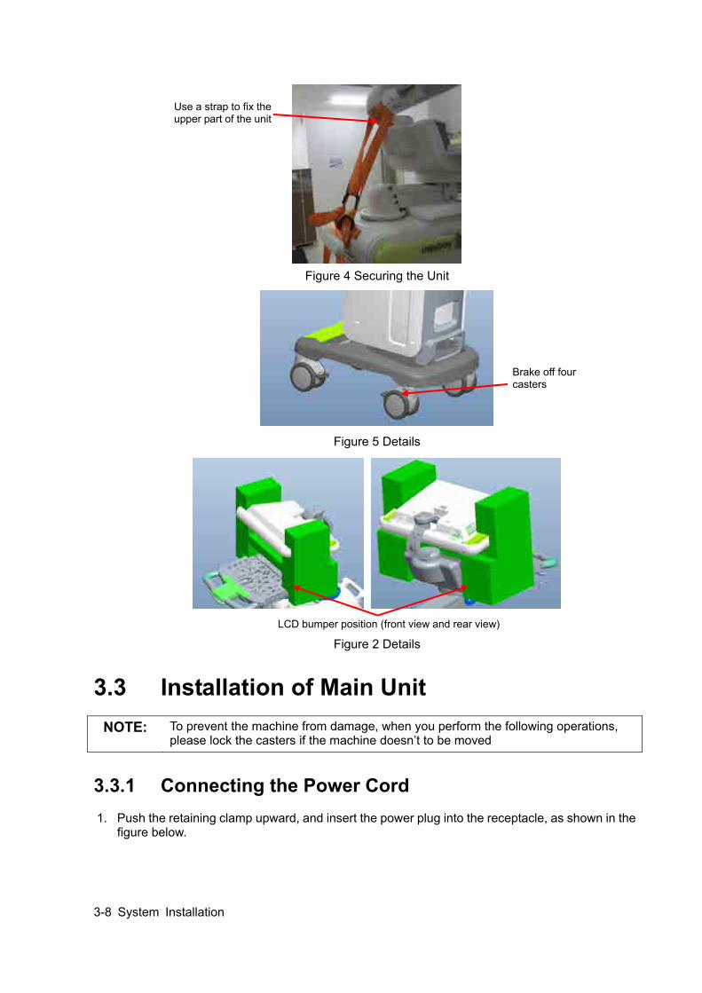
3.3.1 Connecting the Power Cord 1. Push the retaining clamp upward, and insert the power plug into the receptacle, as shown in the
figure below.
Use a strap to fix the upper part of the unit
Brake off four casters
LCD bumper position (front view and rear view)
System Installation 3-9
2. Push the retaining clamp downward, and lock the power cord, as shown in the figure below.
3. Plug the other end power plug into an appropriate outlet. The grounding terminal should be
connected with a power grounding cable to ensure that protective grounding works normally.
NOTE: Make sure to allow sufficient slack in the cable so that the plug is not pulled out of the wall if the system is moved slightly.
3.3.2 Connecting ECG Connect the ECG cable to the corresponding interface on the ECG panel.
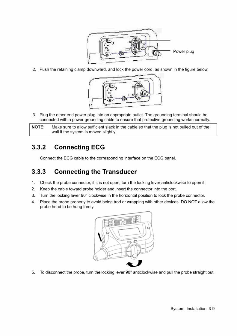
3.3.3 Connecting the Transducer 1. Check the probe connector, if it is not open, turn the locking lever anticlockwise to open it. 2. Keep the cable toward probe holder and insert the connector into the port. 3. Turn the locking lever 90° clockwise in the horizontal position to lock the probe connector. 4. Place the probe properly to avoid being trod or wrapping with other devices. DO NOT allow the
probe head to be hung freely.
5. To disconnect the probe, turn the locking lever 90° anticlockwise and pull the probe straight out.
Power plug
3-10 System Installation
NOTE: Before inserting the connector into the probe port, inspect the connector pin. If the pin is
bent, do not use the probe until it has been inspected / repaired / replaced.
3.4 Installing Peripherals For the models of the supported peripherals, please refer to “2.1.3 Peripherals Supported”.
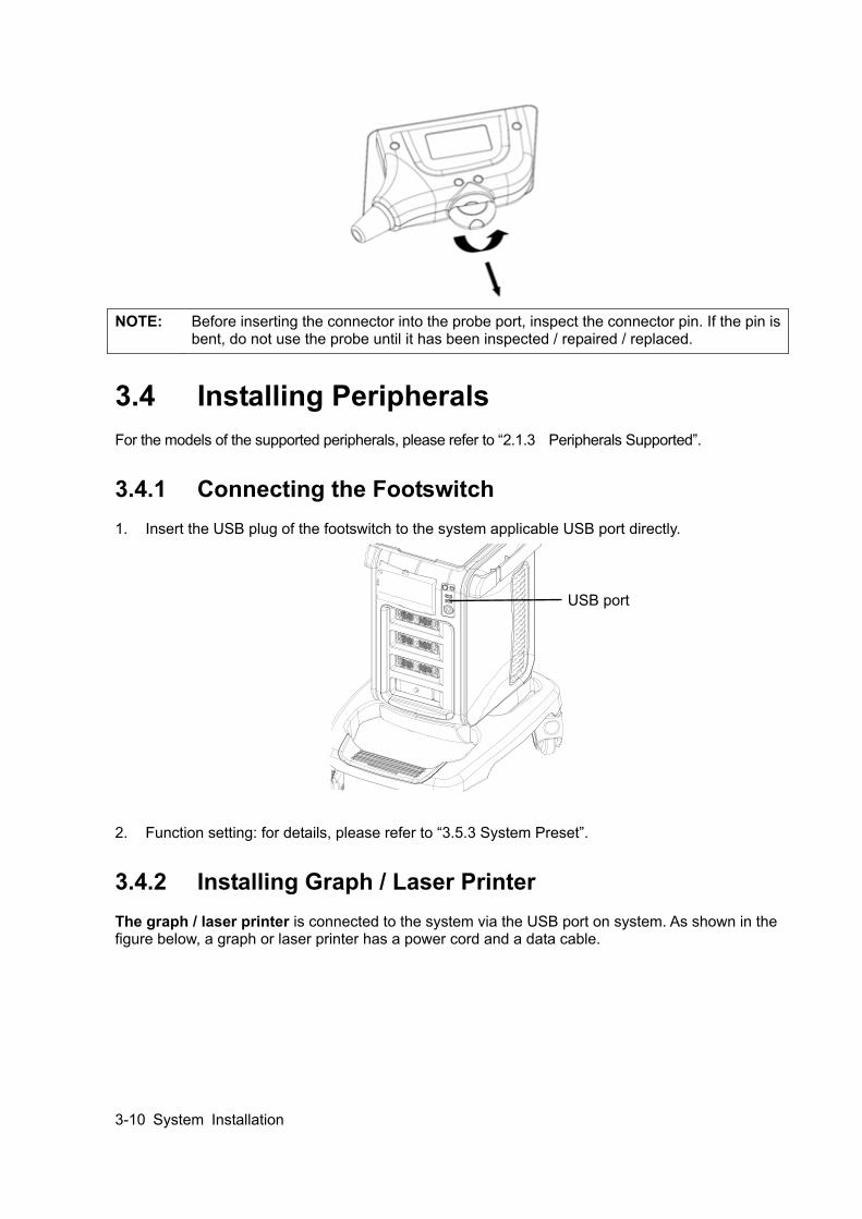
3.4.1 Connecting the Footswitch 1. Insert the USB plug of the footswitch to the system applicable USB port directly.
2. Function setting: for details, please refer to “3.5.3 System Preset”.
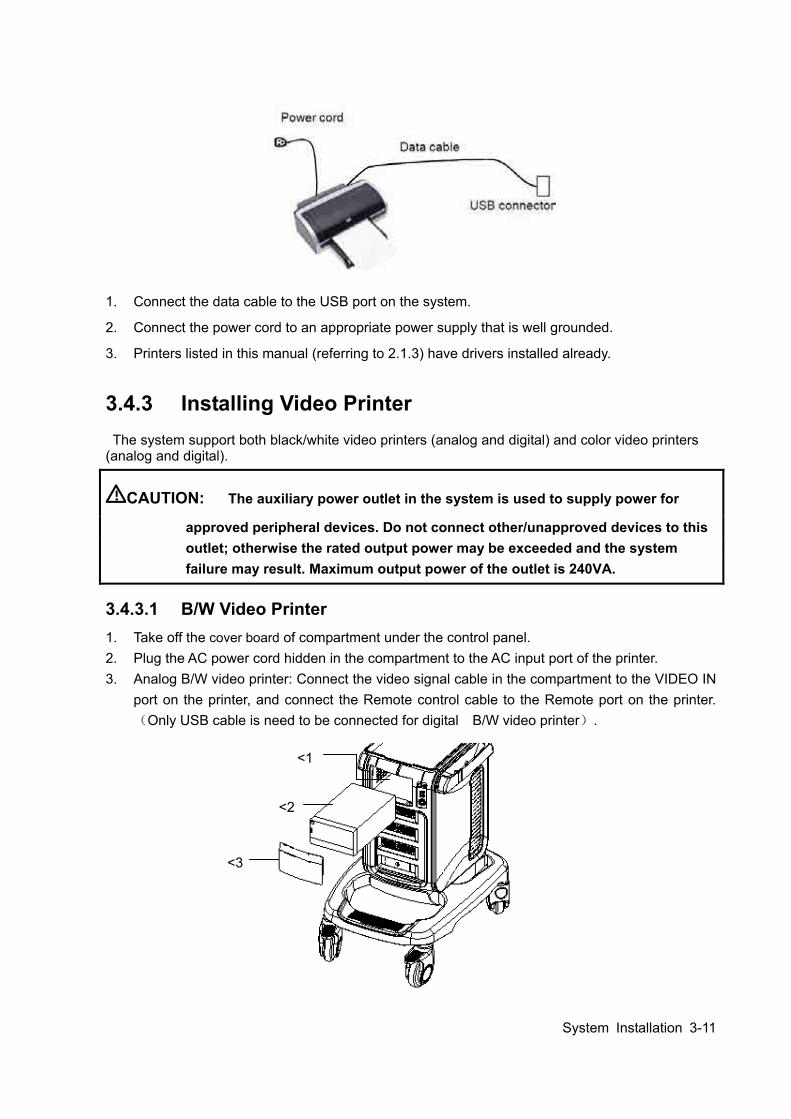
3.4.2 Installing Graph / Laser Printer The graph / laser printer is connected to the system via the USB port on system. As shown in the figure below, a graph or laser printer has a power cord and a data cable.
USB port
System Installation 3-11
1. Connect the data cable to the USB port on the system.
2. Connect the power cord to an appropriate power supply that is well grounded.
3. Printers listed in this manual (referring to 2.1.3) have drivers installed already.
3.4.3 Installing Video Printer The system support both black/white video printers (analog and digital) and color video printers
(analog and digital).
CAUTION: The auxiliary power outlet in the system is used to supply power for
approved peripheral devices. Do not connect other/unapproved devices to this outlet; otherwise the rated output power may be exceeded and the system failure may result. Maximum output power of the outlet is 240VA.
3.4.3.1 B/W Video Printer 1. Take off the cover board of compartment under the control panel. 2. Plug the AC power cord hidden in the compartment to the AC input port of the printer. 3. Analog B/W video printer: Connect the video signal cable in the compartment to the VIDEO IN
port on the printer, and connect the Remote control cable to the Remote port on the printer.(Only USB cable is need to be connected for digital B/W video printer).
<1>
<2>
<3>
3-12 System Installation
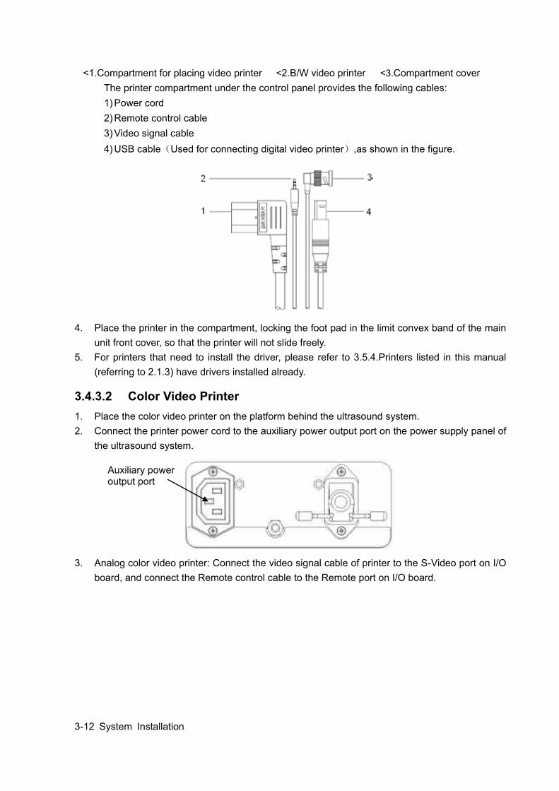
<1.Compartment for placing video printer <2.B/W video printer <3.Compartment cover The printer compartment under the control panel provides the following cables: 1) Power cord 2) Remote control cable 3) Video signal cable 4) USB cable(Used for connecting digital video printer),as shown in the figure.
4. Place the printer in the compartment, locking the foot pad in the limit convex band of the main unit front cover, so that the printer will not slide freely.
5. For printers that need to install the driver, please refer to 3.5.4.Printers listed in this manual (referring to 2.1.3) have drivers installed already.
3.4.3.2 Color Video Printer 1. Place the color video printer on the platform behind the ultrasound system. 2. Connect the printer power cord to the auxiliary power output port on the power supply panel of
the ultrasound system.
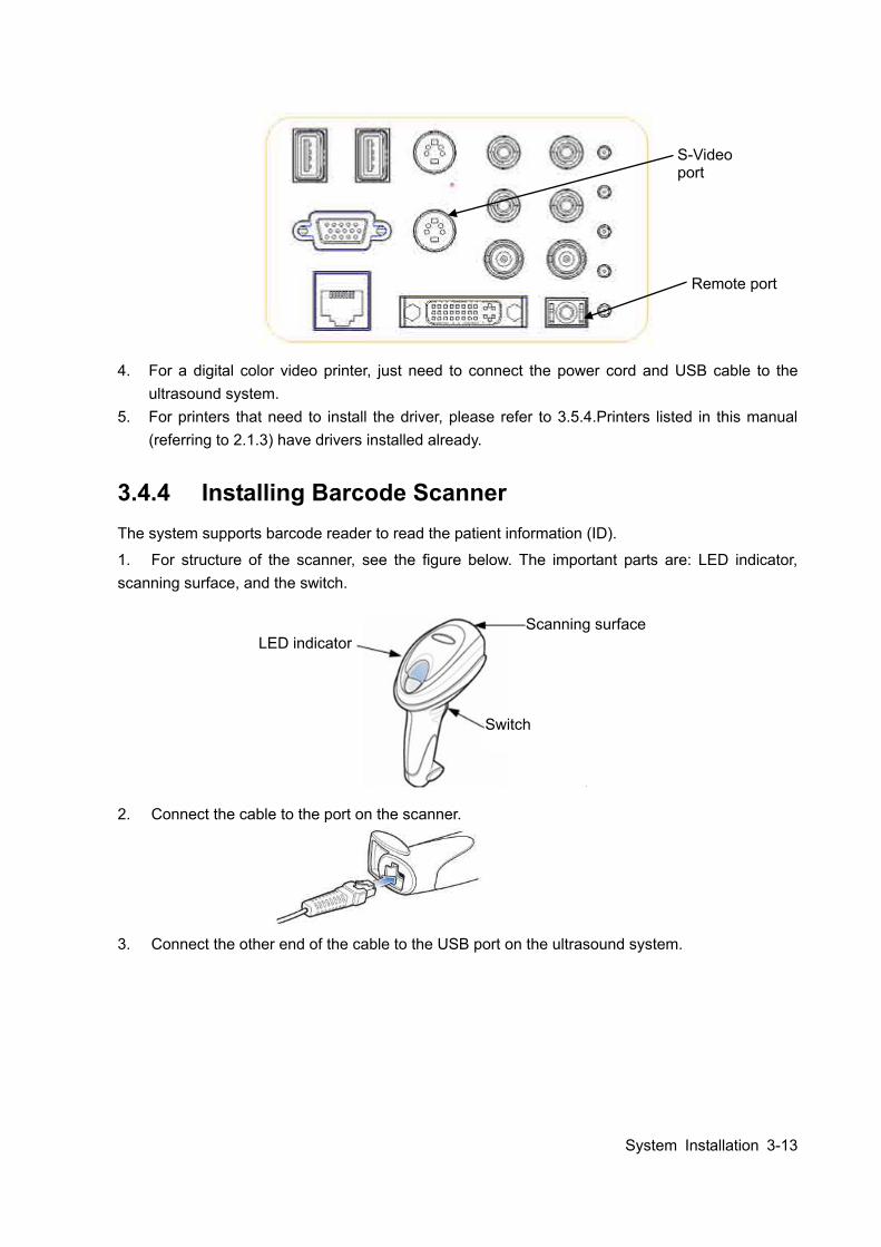
3. Analog color video printer: Connect the video signal cable of printer to the S-Video port on I/O board, and connect the Remote control cable to the Remote port on I/O board.
Auxiliary power output port
System Installation 3-13
4. For a digital color video printer, just need to connect the power cord and USB cable to the ultrasound system.
5. For printers that need to install the driver, please refer to 3.5.4.Printers listed in this manual (referring to 2.1.3) have drivers installed already.
3.4.4 Installing Barcode Scanner The system supports barcode reader to read the patient information (ID).
1. For structure of the scanner, see the figure below. The important parts are: LED indicator, scanning surface, and the switch.
2. Connect the cable to the port on the scanner.
3. Connect the other end of the cable to the USB port on the ultrasound system.
Switch
Scanning surface LED indicator
Remote port
S-Video port
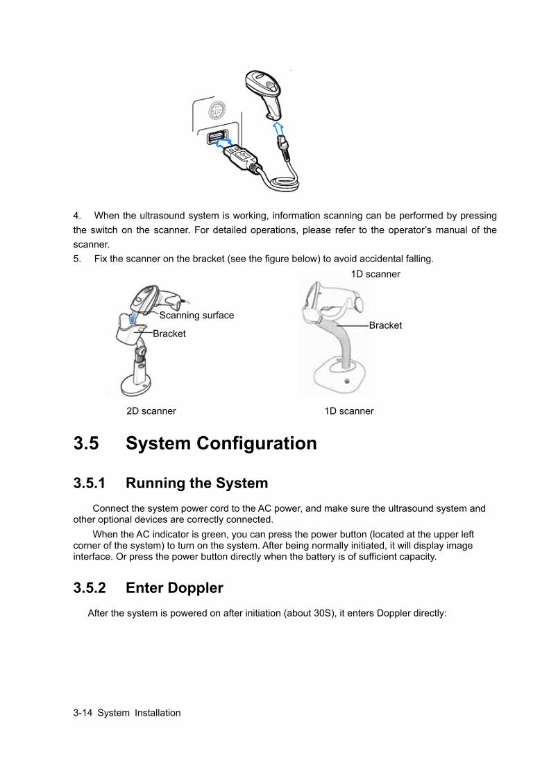
3-14 System Installation
4. When the ultrasound system is working, information scanning can be performed by pressing the switch on the scanner. For detailed operations, please refer to the operator’s manual of the scanner. 5. Fix the scanner on the bracket (see the figure below) to avoid accidental falling.
2D scanner 1D scanner
3.5 System Configuration
3.5.1 Running the System Connect the system power cord to the AC power, and make sure the ultrasound system and
other optional devices are correctly connected. When the AC indicator is green, you can press the power button (located at the upper left
corner of the system) to turn on the system. After being normally initiated, it will display image interface. Or press the power button directly when the battery is of sufficient capacity.
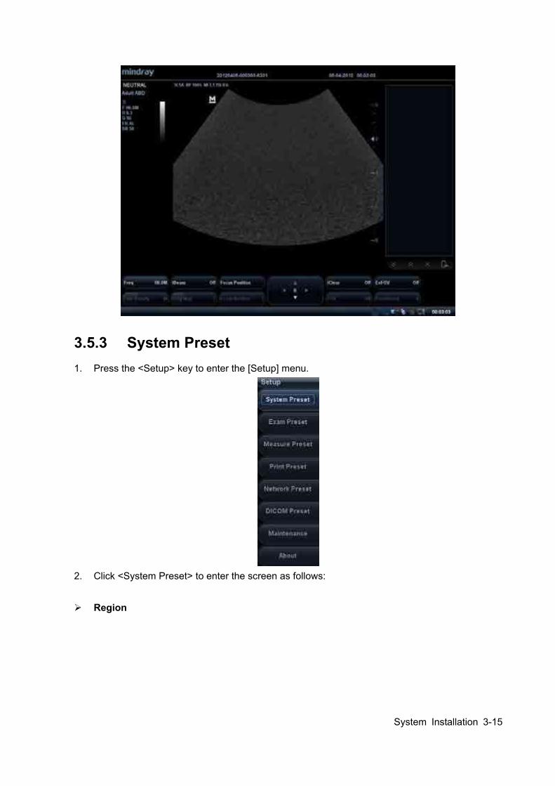
3.5.2 Enter Doppler After the system is powered on after initiation (about 30S), it enters Doppler directly:
Bracket Bracket
Scanning surface
1D scanner
System Installation 3-15
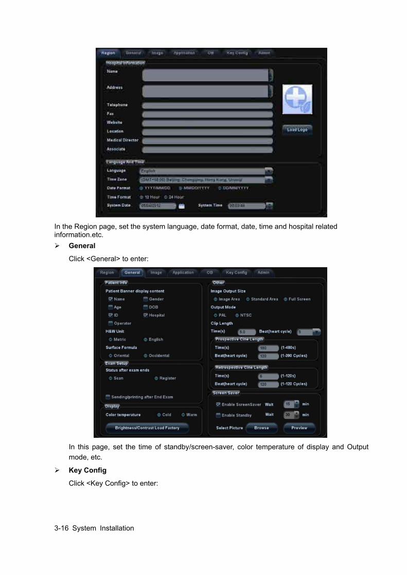
3.5.3 System Preset 1. Press the <Setup> key to enter the [Setup] menu.
2. Click <System Preset> to enter the screen as follows:
Region
3-16 System Installation
In the Region page, set the system language, date format, date, time and hospital related information.etc. General
Click <General> to enter:
In this page, set the time of standby/screen-saver, color temperature of display and Output mode, etc.
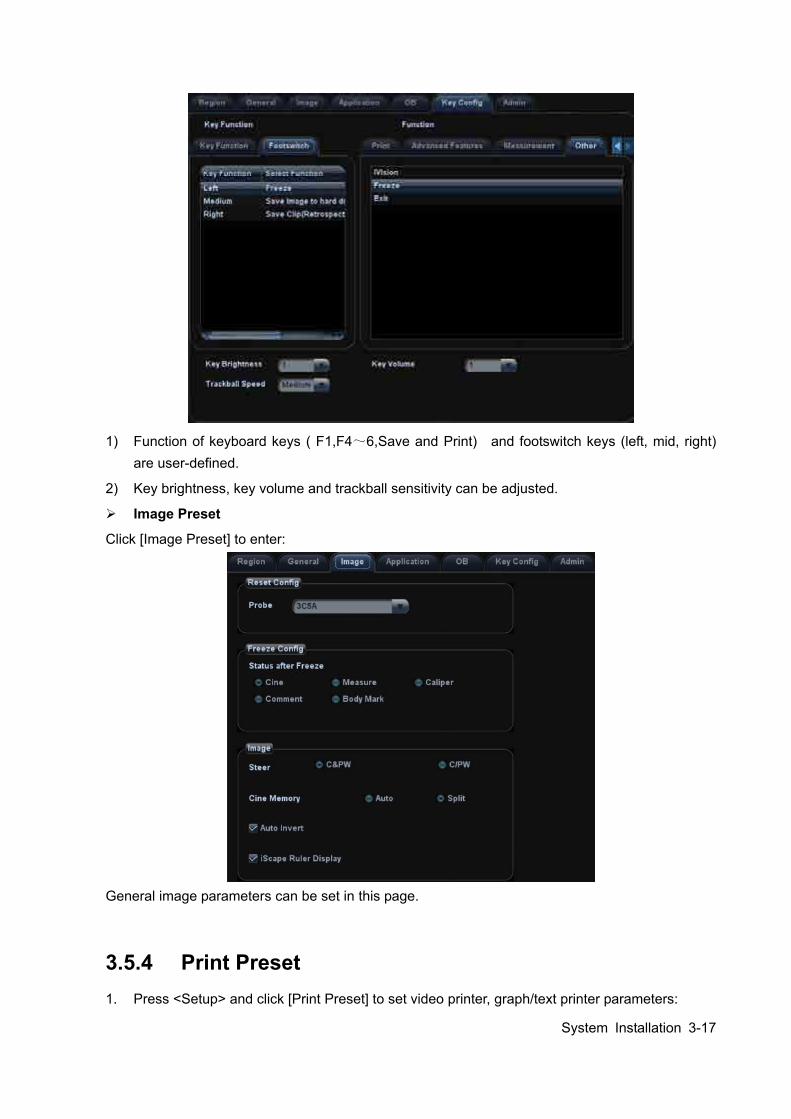
Key Config
Click <Key Config> to enter:
System Installation 3-17
1) Function of keyboard keys ( F1,F4~6,Save and Print) and footswitch keys (left, mid, right)
are user-defined.
2) Key brightness, key volume and trackball sensitivity can be adjusted.
Image Preset
Click [Image Preset] to enter:
General image parameters can be set in this page.
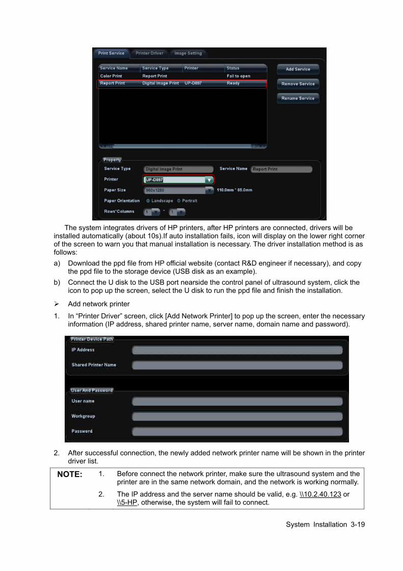
3.5.4 Print Preset 1. Press <Setup> and click [Print Preset] to set video printer, graph/text printer parameters:

3-18 System Installation
2. After connecting the local printer, Click “Printer Driver”, the system will display the printer name
and status (Ready) automatically which already installed printer driver successfully.
3. Return “Printer Service” page, Select the corresponding service from the printer list and
increase the service.
System Installation 3-19
The system integrates drivers of HP printers, after HP printers are connected, drivers will be
installed automatically (about 10s).If auto installation fails, icon will display on the lower right corner of the screen to warn you that manual installation is necessary. The driver installation method is as follows: a) Download the ppd file from HP official website (contact R&D engineer if necessary), and copy
the ppd file to the storage device (USB disk as an example). b) Connect the U disk to the USB port nearside the control panel of ultrasound system, click the
icon to pop up the screen, select the U disk to run the ppd file and finish the installation.
Add network printer
1. In “Printer Driver” screen, click [Add Network Printer] to pop up the screen, enter the necessary information (IP address, shared printer name, server name, domain name and password).
2. After successful connection, the newly added network printer name will be shown in the printer driver list.
NOTE: 1. Before connect the network printer, make sure the ultrasound system and the printer are in the same network domain, and the network is working normally.
2. The IP address and the server name should be valid, e.g. \\10.2.40.123 or \\5-HP, otherwise, the system will fail to connect.
3-20 System Installation
3. If the server has set accessing limitation, the system will prompt a dialogue
box to identify the user. Enter the correct user name, domain name and password, and then click [OK].
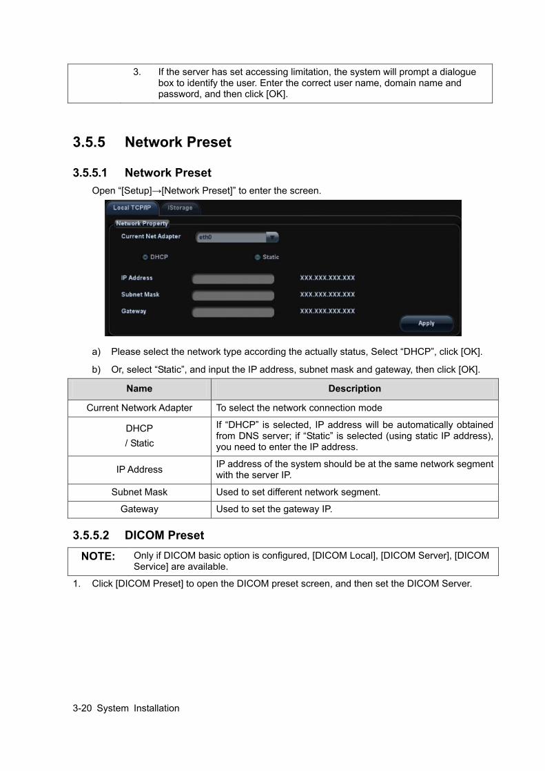
3.5.5 Network Preset
3.5.5.1 Network Preset Open “[Setup]→[Network Preset]” to enter the screen.
a) Please select the network type according the actually status, Select “DHCP”, click [OK].
b) Or, select “Static”, and input the IP address, subnet mask and gateway, then click [OK].
Name Description
Current Network Adapter To select the network connection mode
DHCP / Static
If “DHCP” is selected, IP address will be automatically obtained from DNS server; if “Static” is selected (using static IP address), you need to enter the IP address.
IP Address IP address of the system should be at the same network segment with the server IP.
Subnet Mask Used to set different network segment.
Gateway Used to set the gateway IP.
3.5.5.2 DICOM Preset NOTE: Only if DICOM basic option is configured, [DICOM Local], [DICOM Server], [DICOM
Service] are available.
1. Click [DICOM Preset] to open the DICOM preset screen, and then set the DICOM Server.
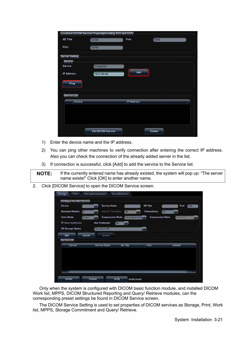
System Installation 3-21
1) Enter the device name and the IP address.
2) You can ping other machines to verify connection after entering the correct IP address. Also you can check the connection of the already added server in the list.
3) If connection is successful, click [Add] to add the service to the Service list.
NOTE: If the currently entered name has already existed, the system will pop up: “The server name exists!” Click [OK] to enter another name.
2. Click [DICOM Service] to open the DICOM Service screen.
Only when the system is configured with DICOM basic function module, and installed DICOM
Work list, MPPS, DICOM Structured Reporting and Query/ Retrieve modules, can the corresponding preset settings be found in DICOM Service screen.
The DICOM Service Setting is used to set properties of DICOM services as Storage, Print, Work list, MPPS, Storage Commitment and Query/ Retrieve.
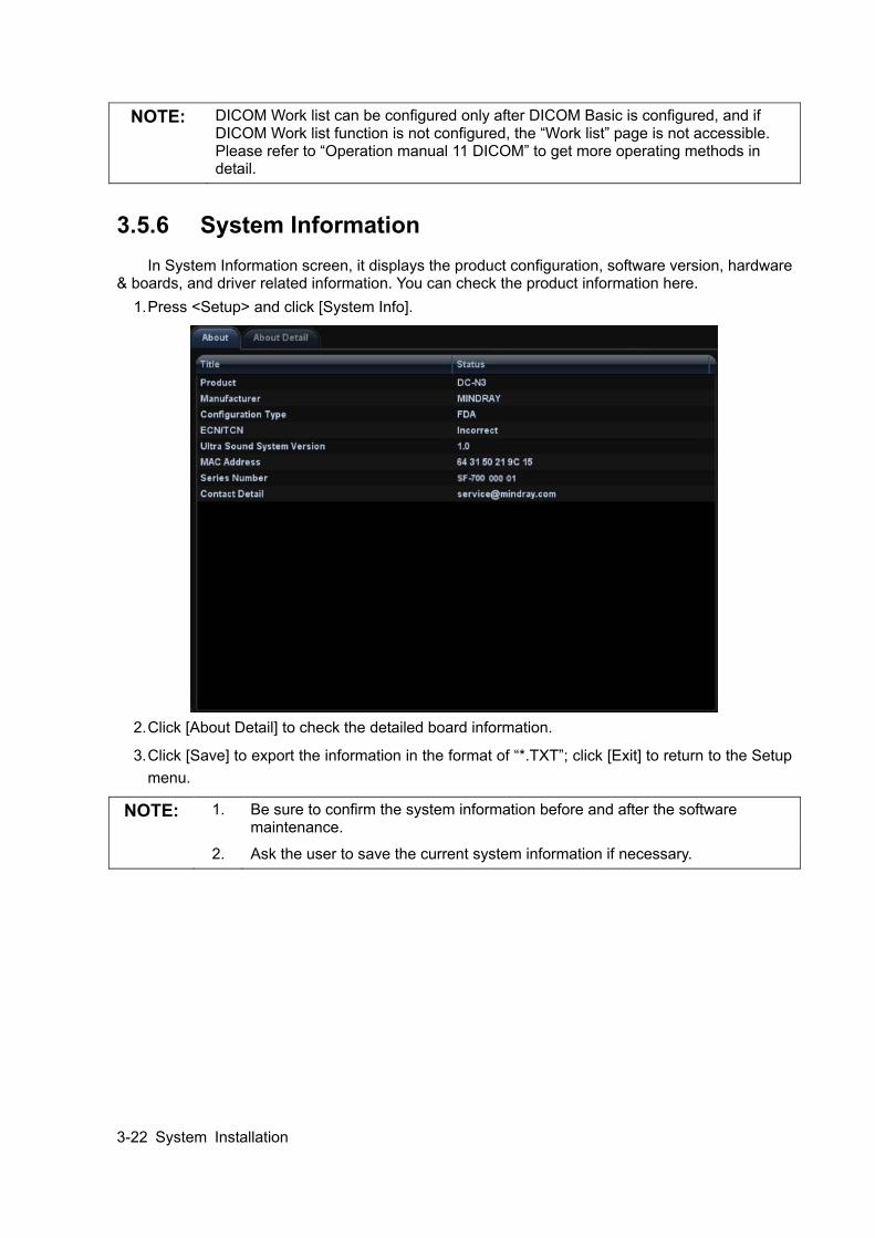
3-22 System Installation
NOTE: DICOM Work list can be configured only after DICOM Basic is configured, and if DICOM Work list function is not configured, the “Work list” page is not accessible. Please refer to “Operation manual 11 DICOM” to get more operating methods in detail.
3.5.6 System Information In System Information screen, it displays the product configuration, software version, hardware
& boards, and driver related information. You can check the product information here. 1. Press <Setup> and click [System Info].
2. Click [About Detail] to check the detailed board information.
3. Click [Save] to export the information in the format of “*.TXT”; click [Exit] to return to the Setup menu.
NOTE: 1. Be sure to confirm the system information before and after the software maintenance.
2. Ask the user to save the current system information if necessary.
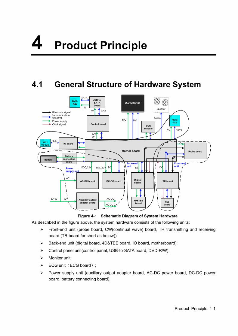
Product Principle 4-1
4 Product Principle
4.1 General Structure of Hardware System
CW board
Digital board TR board
Mother board
AC-DC board DC-DC board
Auxiliary output adapter board
IO board
Control panel
Probe board
Communication &control
Power supply
Ultrasonic signal
USB-to- SATA board
LCD Monitor
Hard disk
DVD-R/W
Speaker
Battery connecting
boardBattery
WiFimodule
AC
AC AC OUTAC IN
AC OUT
EDC_12V EDC_12V DC DC DC
12V5V
12V DVIAudio
5V SATA
5V USB
5V
SATA
PCIE
ECG module
Front-endunit
Power supply unit
Back-end unit
4D&TEEboard
DC
Clock signal
Figure 4-1 Schematic Diagram of System Hardware
As described in the figure above, the system hardware consists of the following units:
Front-end unit (probe board, CW(continual wave) board, TR transmitting and receiving board (TR board for short as below));
Back-end unit (digital board, 4D&TEE board, IO board, motherboard);
Control panel unit(control panel, USB-to-SATA board, DVD-R/W);
Monitor unit;
ECG unit(ECG board);
Power supply unit (auxiliary output adapter board, AC-DC power board, DC-DC power board, battery connecting board).
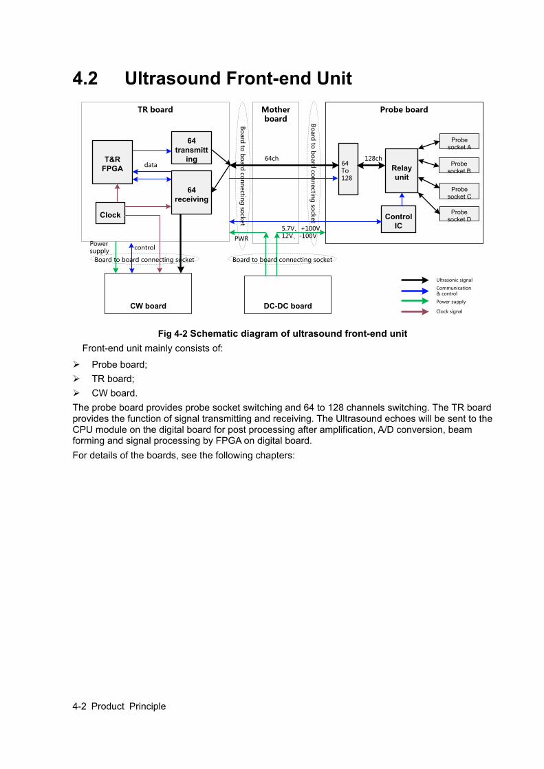
4-2 Product Principle
4.2 Ultrasound Front-end Unit
CW board
TR board Probe boardMother board
DC-DC board
64To128
Relay unit
Probe socket A
Probe socket B
Probe socket C
Probe socket DControl
IC
Communication & control
Power supply
Ultrasonic signal
64ch 128ch
5.7V、+100V12V、-100V
64transmitt
ing
64receiving
T&RFPGA
Power supply
control
Clock
Clock signal
PWR
data
Bo
ard
to b
oard
con
nectin
g so
cket
Bo
ard
to b
oard
con
nectin
g so
cket
Board to board connecting socket Board to board connecting socket
Fig 4-2 Schematic diagram of ultrasound front-end unit
Front-end unit mainly consists of:
Probe board; TR board; CW board. The probe board provides probe socket switching and 64 to 128 channels switching. The TR board provides the function of signal transmitting and receiving. The Ultrasound echoes will be sent to the CPU module on the digital board for post processing after amplification, A/D conversion, beam forming and signal processing by FPGA on digital board. For details of the boards, see the following chapters:
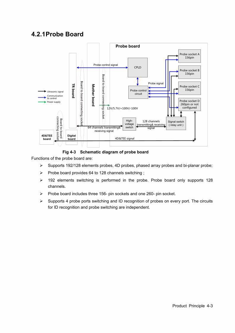
Product Principle 4-3
4.2.1 Probe Board
Digital board
Mo
ther b
oard
Probe board
Probe socket D260pin or not
configured
Probe socket C156pin
Probe socket B156pin
Probe socket A156pin
Signal switch ( relay unit )
CPLD
Probe signal
64 channels transmitting& receiving signal
4D&TEE signal
Probe control circuit
Probe control signal
12V/5.7V/+100V/-100V
High-voltage switch
128 channels transmitting& receiving
signal B
oard
to b
oard
con
nectin
g so
cket
TR
bo
ard
4D&TEEboard
Bo
ard
to b
oard
con
nectin
g so
cket
Communication& control
Power supply
Ultrasonic signal
Bo
ard
to b
oard
co
nn
ectin
g so
cket
Fig 4-3 Schematic diagram of probe board
Functions of the probe board are:
Supports 192/128 elements probes, 4D probes, phased array probes and bi-planar probe;
Probe board provides 64 to 128 channels switching ;
192 elements switching is performed in the probe. Probe board only supports 128 channels.
Probe board includes three 156- pin sockets and one 260- pin socket.
Supports 4 probe ports switching and ID recognition of probes on every port. The circuits for ID recognition and probe switching are independent.

4-4 Product Principle
4.2.2 TR Board
Board-to-board connecting socket
T&R board
Mo
ther b
oard
CW board
High-voltage pulse output
circuit
Drive circuit
ATGC
High-voltage isolation
AFE chipx8
Clock
T&RFPGA
Clock circuit
Pro
be b
oard
12V/-12V/5.7V/-5.7V/4V/3.3V/2.5V/1.8V/PHV1P/PHV1N
12V/5.7V/-5.7V/4V
64ch
64ch
64ch
64ch
Board-to-board connecting socket
Board-to-board
connecting socket
Cable-to-board connecting socket
T&R signal of pencil probe
Communication
& control
Power supply
Ultrasonic signal
Clock signal
Dig
ital b
oard
Board-to-board
connecting socket
Fig 4-4 Schematic Diagram of TR Board
The TR board is designed for signal transmitting and receiving. The system can communicate with the TR board via the communication control bus.
Generate 64-channel transmission waveform
Generate 64-channel transmission waveform according to the scanning sequence and control parameter.
The 64-channel transmission waveforms are driven into 64-channel high-voltage transmission pulses by the drive circuit.
Generate 64-channel signal receiving
High-voltage isolation.
Amplification and A/D conversion of ultrasound echoes, performed by the integrated front-end chip.
ATGC module, voltage gain control module.
Beam former, performed by FPGA.
Clock module, the clock source of the whole front-end unit is on the TR board, clock buffer is sent to the corresponding board after fan-outing.
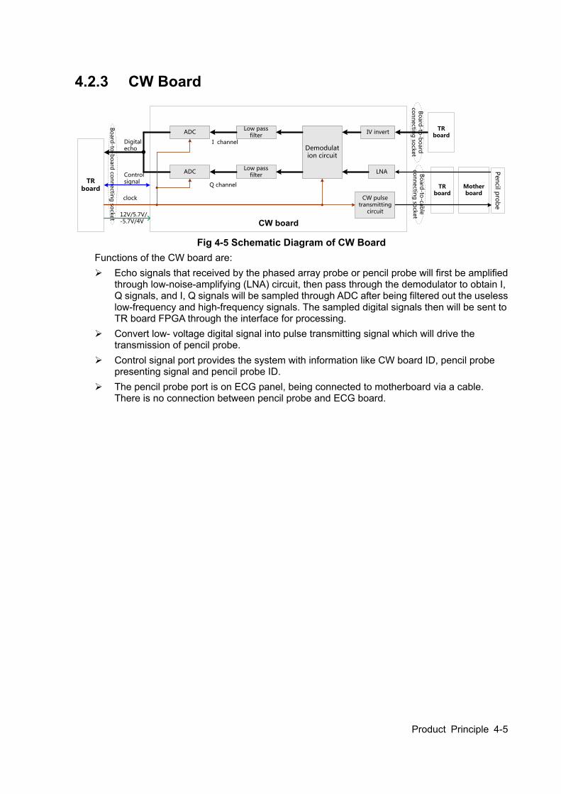
Product Principle 4-5
4.2.3 CW Board
Mother board
TR board
CW board
Low pass filter
ADC
Q channel
I channel
Low pass filter
ADC IV invert
Demodulation circuit
LNA
TR board
TR board
Pen
cil pro
be
CW pulse transmitting
circuit
Bo
ard
-to-b
oard
con
nectin
g so
cket
Bo
ard
-to-b
oard
co
nn
ectin
g so
cket
Bo
ard
-to-ca
ble
co
nn
ectin
g so
cket
Digital echo
Control signal
12V/5.7V/-5.7V/4V
clock
Fig 4-5 Schematic Diagram of CW Board
Functions of the CW board are: Echo signals that received by the phased array probe or pencil probe will first be amplified
through low-noise-amplifying (LNA) circuit, then pass through the demodulator to obtain I, Q signals, and I, Q signals will be sampled through ADC after being filtered out the useless low-frequency and high-frequency signals. The sampled digital signals then will be sent to TR board FPGA through the interface for processing.
Convert low- voltage digital signal into pulse transmitting signal which will drive the transmission of pencil probe.
Control signal port provides the system with information like CW board ID, pencil probe presenting signal and pencil probe ID.
The pencil probe port is on ECG panel, being connected to motherboard via a cable. There is no connection between pencil probe and ECG board.

4-6 Product Principle
4.3 Ultrasound Back-end Unit
4D&TEE board
IO board
Digital boardMother board
DC-DC board
Communication
& control
Power supply
Ultrasonic signal
PC12V、12V、5V、5Vstb、-5.7V、3.3V、-12V
Clock signal
PC12V、5V、3.3V
Clock(from T&R board) DSPFPGA
Multifunctional FPGA
WiFimodule
CPU module
PCIEPHY
PCIE
LPC
Network DVI
VGA
Videoout
S_Videoout
VideoinS_Video
in
Lineout
Line in
Remote
USBX2
Audio,video
USB、PCIE
Status indicating signal, debugging signal.
PCIE
Hard disk
SATA
5V、3.3V
3.3V4D&TEE signal(to probe board)
12V、-12V
Control panel
Power supply control panel
Communication signal,with front-end
Fig 4-6 Schematic Diagram of Back-end Unit
The back-end unit mainly consists of: digital board, motherboard, IO board, 4D&TEE board, etc. See the diagram above.
4.3.1 Digital Board & IO board The block diagram of the digital board is shown as below:
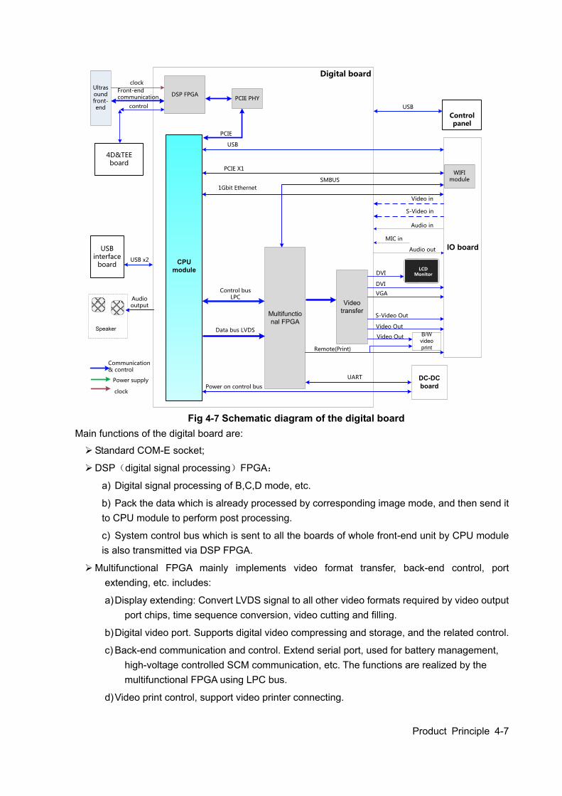
Product Principle 4-7
Digital board
Video transferMultifunctio
nal FPGA
CPU module DVI
VGA
S-Video Out
Video Out
Remote(Print)
1Gbit Ethernet
USB
Audio out
Audio output
Speaker
Control bus LPC
Video in
S-Video in
Audio in
MIC in
DVI
IO board
Video Out
PCIE X1
B/W video print
Ultrasound front-end
USB x2
UART DC-DC board
Data bus LVDS
USB interface
board
DSP FPGAPCIE PHY
Communication & control
Power supply
clock
4D&TEE board
PCIE
clock
Front-end communication
control
Control panel
Power on control bus
LCD Monitor
USB
WIFI moduleSMBUS
Fig 4-7 Schematic diagram of the digital board
Main functions of the digital board are:
Standard COM-E socket;
DSP(digital signal processing)FPGA:
a) Digital signal processing of B,C,D mode, etc.
b) Pack the data which is already processed by corresponding image mode, and then send it to CPU module to perform post processing.
c) System control bus which is sent to all the boards of whole front-end unit by CPU module is also transmitted via DSP FPGA.
Multifunctional FPGA mainly implements video format transfer, back-end control, port extending, etc. includes:
a) Display extending: Convert LVDS signal to all other video formats required by video output port chips, time sequence conversion, video cutting and filling.
b) Digital video port. Supports digital video compressing and storage, and the related control.
c) Back-end communication and control. Extend serial port, used for battery management, high-voltage controlled SCM communication, etc. The functions are realized by the multifunctional FPGA using LPC bus.
d) Video print control, support video printer connecting.
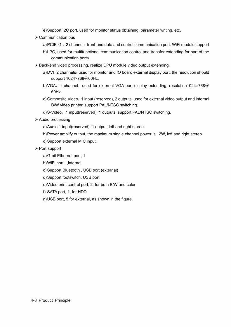
4-8 Product Principle
e) Support I2C port, used for monitor status obtaining, parameter writing, etc.
Communication bus
a) PCIE ×1,2 channel;front-end data and control communication port. WiFi module support
b) LPC, used for multifunctional communication control and transfer extending for part of the communication ports.
Back-end video processing, realize CPU module video output extending.
a) DVI,2 channels;used for monitor and IO board external display port, the resolution should support 1024×768@60Hz.
b) VGA,1 channel;used for external VGA port display extending, resolution1024×768@60Hz.
c) Composite Video,1 input (reserved), 2 outputs, used for external video output and internal B/W video printer, support PAL/NTSC switching.
d) S-Video,1 input(reserved), 1 outputs, support PAL/NTSC switching.
Audio processing
a) Audio 1 input(reserved), 1 output, left and right stereo
b) Power amplify output, the maximum single channel power is 12W, left and right stereo
c) Support external MIC input.
Port support
a) G-bit Ethernet port, 1
b) WiFi port,1,internal
c) Support Bluetooth , USB port (external)
d) Support footswitch, USB port
e) Video print control port, 2, for both B/W and color
f) SATA port, 1, for HDD
g) USB port, 5 for external, as shown in the figure.
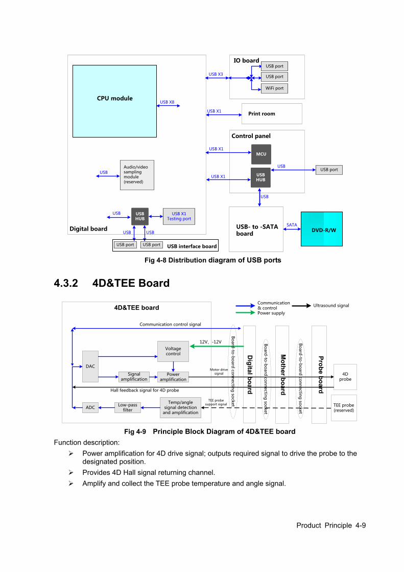
Product Principle 4-9
Digital board
CPU module
IO board
Control panel
USB X1Testing port
USB X8
USB X3
USB X1
Audio/video sampling module(reserved)
USBUSB HUB
MCU
USB- to -SATA board
USB
USB
USB port
USB port
WiFi port
USB port
SATA
DVD-R/W
USB X1Print room
USBHUB
USB
USB USB
USB X1
USB interface boardUSB port USB port
Fig 4-8 Distribution diagram of USB ports
4.3.2 4D&TEE Board
Digital board
Mother board
Probe board
4D&TEE board
Low-pass filter
ADC
Signal amplification
DAC
Temp/angle signal detection
and amplification
Communication control signal
Power amplification
Voltage control
Motor drive signal
Hall feedback signal for 4D probe
TEE probe support signal
12V、-12V Bo
ard
-to-b
oard
con
nectin
g so
cket
4D probe
TEE probe(reserved)
Bo
ard
-to-b
oard
con
nectin
g so
cket
Communication & controlPower supply
Ultrasound signal
Bo
ard
-to-b
oard
con
nectin
g so
cket
Fig 4-9 Principle Block Diagram of 4D&TEE board
Function description: Power amplification for 4D drive signal; outputs required signal to drive the probe to the
designated position. Provides 4D Hall signal returning channel. Amplify and collect the TEE probe temperature and angle signal.
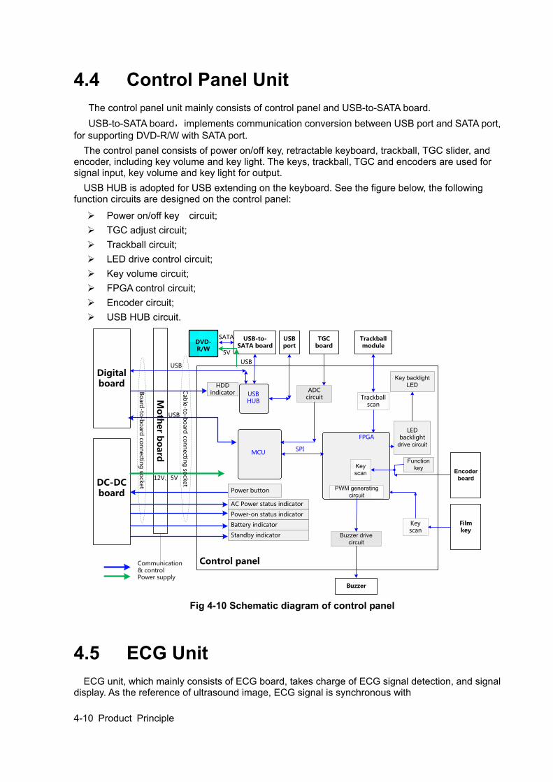
4-10 Product Principle
4.4 Control Panel Unit The control panel unit mainly consists of control panel and USB-to-SATA board. USB-to-SATA board,implements communication conversion between USB port and SATA port, for supporting DVD-R/W with SATA port. The control panel consists of power on/off key, retractable keyboard, trackball, TGC slider, and encoder, including key volume and key light. The keys, trackball, TGC and encoders are used for signal input, key volume and key light for output. USB HUB is adopted for USB extending on the keyboard. See the figure below, the following function circuits are designed on the control panel:
Power on/off key circuit; TGC adjust circuit; Trackball circuit; LED drive control circuit; Key volume circuit; FPGA control circuit; Encoder circuit; USB HUB circuit.
Mo
ther b
oard
Control panel
USB
DC-DC board
AC Power status indicator
Power button
Digital board
TGC board
Trackball module
Function key Encoder
board
Key scan
LED backlight
drive circuit
Key backlight LED
ADC circuit
Buzzer
Buzzer drive circuit
Trackball scan
PWM generating circuit
FPGA
12V、5V
MCUSPI
USB
USBHUB
USB-to-SATA board
USBport
Communication & controlPower supply
DVD-R/W
USB
SATA
5V
Key scan
Film key
Bo
ard
-to-b
oard
con
nectin
g so
cket
Cab
le-to
-bo
ard
con
nectin
g so
cket
HDD indicator
Power-on status indicator
Standby indicator
Battery indicator
Fig 4-10 Schematic diagram of control panel
4.5 ECG Unit ECG unit, which mainly consists of ECG board, takes charge of ECG signal detection, and signal display. As the reference of ultrasound image, ECG signal is synchronous with
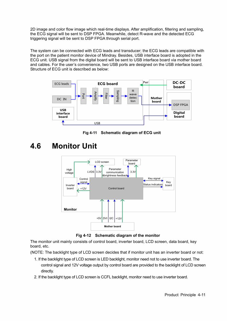
Product Principle 4-11
2D image and color flow image which real-time displays. After amplification, filtering and sampling, the ECG signal will be sent to DSP FPGA. Meanwhile, detect R-wave and the detected ECG triggering signal will be sent to DSP FPGA through serial port. The system can be connected with ECG leads and transducer; the ECG leads are compatible with the port on the patient monitor device of Mindray. Besides, USB interface board is adopted in the ECG unit. USB signal from the digital board will be sent to USB interface board via mother board and cables. For the user’s convenience, two USB ports are designed on the USB interface board. Structure of ECG unit is described as below:
Mother board
Digital board
ECG leads
DC IN
Po
rt
Amplify
Filter
Sampling
R wave detection
DSP FPGA
ECG board DC-DC board
Pwr
USB interface
board
USB
Fig 4-11 Schematic diagram of ECG unit
4.6 Monitor Unit
Control boardInverter board
Key board
Parameter boardLCD screen
Mother board
+12V
+12V
Control signal
Key signal
+5V DVI I2C
LVDS 3.3V 3.3VParameter
communication &brightness feedback
Monitor
High voltage
Status indicators
Fig 4-12 Schematic diagram of the monitor
The monitor unit mainly consists of control board, inverter board, LCD screen, data board, key board, etc. (NOTE: The backlight type of LCD screen decides that if monitor unit has an inverter board or not:
1. If the backlight type of LCD screen is LED backlight, monitor need not to use inverter board. The control signal and 12V voltage output by control board are provided to the backlight of LCD screen directly.
2. If the backlight type of LCD screen is CCFL backlight, monitor need to use inverter board.
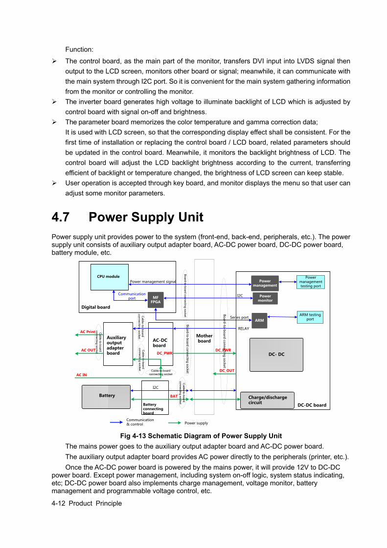
4-12 Product Principle
Function:
The control board, as the main part of the monitor, transfers DVI input into LVDS signal then output to the LCD screen, monitors other board or signal; meanwhile, it can communicate with the main system through I2C port. So it is convenient for the main system gathering information from the monitor or controlling the monitor.
The inverter board generates high voltage to illuminate backlight of LCD which is adjusted by control board with signal on-off and brightness.
The parameter board memorizes the color temperature and gamma correction data; It is used with LCD screen, so that the corresponding display effect shall be consistent. For the first time of installation or replacing the control board / LCD board, related parameters should be updated in the control board. Meanwhile, it monitors the backlight brightness of LCD. The control board will adjust the LCD backlight brightness according to the current, transferring efficient of backlight or temperature changed, the brightness of LCD screen can keep stable.
User operation is accepted through key board, and monitor displays the menu so that user can adjust some monitor parameters.
4.7 Power Supply Unit Power supply unit provides power to the system (front-end, back-end, peripherals, etc.). The power supply unit consists of auxiliary output adapter board, AC-DC power board, DC-DC power board, battery module, etc.
Mother boardAC-DC
board
DC_PWR
AC IN
AC OUT
Auxiliary output adapter board
AC Print
ARM
Power management
DC- DC
Power monitor
Battery
MFFPGA
Digital board
CPU module
DC-DC board
Communication port
I2C
Series port
Power management testing port
ARM testing port
Charge/discharge circuit
BAT
DC_OUT
Power management signal
I2C
Battery connecting board
DC_PWR
Ca
ble
-to-b
oa
rd
co
nn
ectin
g s
ocke
t
Ca
ble
-to-b
oa
rd
co
nn
ectin
g s
ocke
tC
ab
le-to
-bo
ard
co
nn
ectin
g so
cket
Cable-to-board
connecting socket
Ca
ble
-to-b
oa
rd
co
nn
ectin
g s
ocke
t
Bo
ard
-to-b
oa
rd c
on
ne
ctin
g s
ocke
tB
oa
rd-to
-bo
ard
co
nn
ectin
g s
ocke
t
Bo
ard
-to-b
oard
con
nectin
g so
cket
Power supplyCommunication & control
RELAY
Fig 4-13 Schematic Diagram of Power Supply Unit
The mains power goes to the auxiliary output adapter board and AC-DC power board. The auxiliary output adapter board provides AC power directly to the peripherals (printer, etc.). Once the AC-DC power board is powered by the mains power, it will provide 12V to DC-DC
power board. Except power management, including system on-off logic, system status indicating, etc; DC-DC power board also implements charge management, voltage monitor, battery management and programmable voltage control, etc.
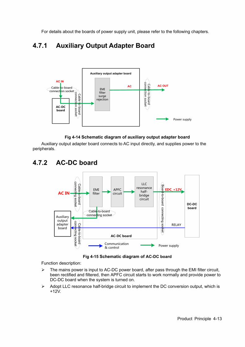
Product Principle 4-13
For details about the boards of power supply unit, please refer to the following chapters.
4.7.1 Auxiliary Output Adapter Board
Auxiliary output adapter board
AC IN
EMI filter surge
rejection
AC-DC board
Cab
le-to
-bo
ard
co
nn
ectio
n so
cket
AC AC OUT
Power supply
Cable-to-board connection socket
Cab
le-to
-bo
ard
co
nn
ectio
n so
cket
Fig 4-14 Schematic diagram of auxiliary output adapter board
Auxiliary output adapter board connects to AC input directly, and supplies power to the peripherals.
4.7.2 AC-DC board
APFCcircuit
EMI filter
AC-DC board
DC-DCboard
EDC_+12V
LLC resonance
half-bridge circuit
Communication & control
Power supply
Auxiliary output adapter board
Bo
ard
-to-b
oa
rd co
nn
ectin
g s
ocke
t
RELAY
Ca
ble
-to-b
oa
rd
co
nn
ectin
g s
ocke
t
Ca
ble
-to-b
oa
rd
co
nn
ectin
g s
ocke
t
AC IN
Cable-to-board
connecting socket
Fig 4-15 Schematic diagram of AC-DC board
Function description: The mains power is input to AC-DC power board, after pass through the EMI filter circuit,
been rectified and filtered, then APFC circuit starts to work normally and provide power to DC-DC board when the system is turned on.
Adopt LLC resonance half-bridge circuit to implement the DC conversion output, which is +12V.
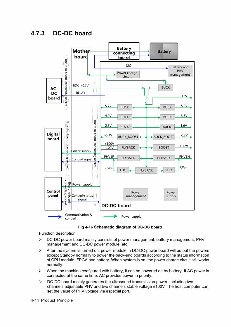
4-14 Product Principle
4.7.3 DC-DC board
Mother board
BUCK
Power charge circuit
BUCKBUCK
BUCK BUCK
BUCK BUCK
BOOSTFLYBACK
FLYBACKFLYBACK
FLYBACK LDOLDO
5.0V
3.3V
1.6V
5.7V
4.0V
2.5V
-100VPC12V
PHV1NPHV1P
CW+ CW-
12V
BUCK_BOOSTBUCK_BOOST-5.7V -12V
+100V
DC-DC board
AC-DC
board
Power management
Power supply
Battery and PHV
management
Digital board
RELAY
EDC_+12V
Bo
ard
-to-b
oa
rd co
nn
ectin
g s
ocke
t
Bo
ard
-to-b
oa
rd co
nn
ectin
g s
ocke
t
Power supply
Control signal
Control panel
Power supply
Control/status signal
Bo
ard
-to-b
oa
rd co
nn
ectin
g s
ocke
tB
oa
rd-to
-bo
ard
co
nn
ectin
g s
ocke
t
BatteryBattery
connecting board
I2C
Communication & control
Power supply
Fig 4-16 Schematic diagram of DC-DC board
Function description: DC-DC power board mainly consists of power management, battery management, PHV
management and DC-DC power module, etc. After the system is turned on, power module in DC-DC power board will output the powers
except Standby normally to power the back-end boards according to the status information of CPU module, FPGA and battery. When system is on, the power charge circuit still works normally.
When the machine configured with battery, it can be powered on by battery. If AC power is connected at the same time, AC provides power in priority.
DC-DC board mainly generates the ultrasound transmission power, including two channels adjustable PHV and two channels stable voltage ±100V. The host computer can set the value of PHV voltage via especial port.

Product Principle 4-15
DC-DC board includes power monitor IC, Which is provided to host computer to obtain the voltage value of special power.
After each circuit module on the board is started, PHV and ±HV are still kept closed, PHV and ±HV will be started only if the IC received the commands from host computer, PHV output voltage is determined by the command of host computer.
4.7.3.1 System Power on Control
Power button on
control panel
Motherboard
DC-DC board
Digital board
CPU module
AC-DCboard
Relay ON
EDC_12V EDC_12V
PWR_BTN_N
PWR_BTN_N
S3#
S4#
S5#
PWRBTN#
PWR_OK
5VSTB
S3#
S4#
S5#
PWRBTN#
PWR_OK
5VSTB
S3# S4#S5#
PW
R_O
KP
WR
BTN
#
5V
STB
D12V
Battery assembly
Battery interface
Battery interface
Relay ON
Fig 4-17 Schematic diagram of system power on control
The related control signals:
No. Control signal Explanation Remarks
1. PWR_BTN_N, PWR_BTN#
The pulse signal, which is generated by the power button on control panel, is transferred to the CPU module through power management FPGA, for system being turned on.
2. S3# Output by CPU module, If it is effective, the CPU module is in standby status (S4# is high), when 5VSTB_CPU which is controlled by power management FPGA is in the charging status.
3. S4# Output by CPU module If it is effective, CPU module is in hibernation status.
4. S5# This signal is not used currently.
5. PWR_OK# Power management FPGA output to CPU module, means 12V power is OK.
6. EDC_12V From AC-DC board to DC-DC board, for generating 3.3VSTB
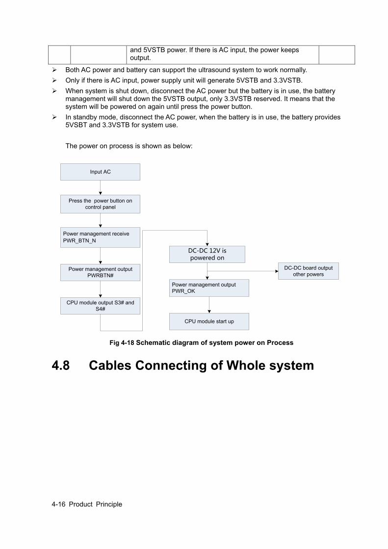
4-16 Product Principle
and 5VSTB power. If there is AC input, the power keeps output.
Both AC power and battery can support the ultrasound system to work normally. Only if there is AC input, power supply unit will generate 5VSTB and 3.3VSTB. When system is shut down, disconnect the AC power but the battery is in use, the battery
management will shut down the 5VSTB output, only 3.3VSTB reserved. It means that the system will be powered on again until press the power button.
In standby mode, disconnect the AC power, when the battery is in use, the battery provides 5VSBT and 3.3VSTB for system use. The power on process is shown as below:
Input AC
Press the power button on control panel
Power management receive PWR_BTN_N
Power management output PWRBTN#
CPU module output S3# and S4#
DC-DC 12V is powered on
Power management output PWR_OK
CPU module start up
DC-DC board output other powers
Fig 4-18 Schematic diagram of system power on Process
4.8 Cables Connecting of Whole system
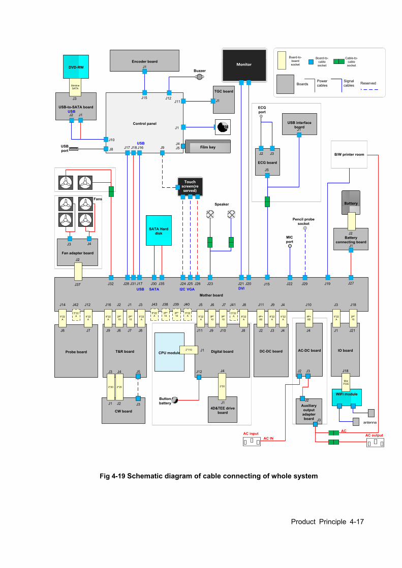
Product Principle 4-17
B/W printer room
CPU module
CW board
Probe board
Mother board
5*22A
5*22A
T&R board Digital board
8*22A
2P*10
2P*10
5*22A
5*22A
3P*10
3P*10
8*22A
DC-DC board
4P+8S
8*22A
5*22A
J14
J8 J7
2*20
J1 J3
J5J3
2*20
J4
J2
Board-to-board socket
Board-to-cable socket
BoardsPower cables
Signal cables
J16 J2 J1 J3
J9 J6 J7 J8
AC-DC board
4P+8S
IO board
5*22A
2P*10
Auxiliary output adapter board
J12
Button battery
2*110
4D&TEE drive board
2*50
J1
J4
J12
J1
J11 J9 J10 J8
J5 J6 J7 J8 J11 J9 J4
J2 J3 J4
J10
J4 J1 J21
J18J3
Fan adapter board
J37
J2
SATA Hard disk
Control panel
Monitor
Touch screen(reserved)
WiFi module
MiniPCIE
Cable-to-cable socket
AC input AC output
J18
antenna
J30 J35J28 J31 J17
J17 J18 J16
J25 J26J24
J9
J20J21
J2
J3
J23
Speaker
J29J22J15J32 J19
AC
AC IN
J27
Battery connecting board
Battery
J2
J1
TGC board
USB-to-SATA board
DVD-RW
SlimlineSATA
J10
J15J11
J1
J1
J2 J1
J3
轨迹球
Encoder boardJ1
J8
ECG board
USB interface board
J3 J4
J5
J2 J3
J1
ECGport
Pencil probe socket
MICport
USBport
Fans
Film key
USB SATA VGAI2C DVI
USB
J4
Buzzer
J12
J5USB
J2
Reserved
5*22A
J42
8*22A
2P*10
2P*10
5*22A
J43 J38 J39 J40
5*22A
J41
J3
Fig 4-19 Schematic diagram of cable connecting of whole system


Function and Performance Checking Method 5-1
5 Function and Performance Checking Method
5.1 Instruction The chapter supplies the method to verify main function and performance of product. This is only used for reference, not preventive execution. Function checking and testing of this part shall be carried out by Mindray service engineers and the user together.
5.2 System Running Status
5.2.1 Running Status 1. The ultrasound system can be turned on or off normally, working normally, no any abnormal
noise and phenomenon appear when the system is running.
2. The fan starts to work as soon as the system is turned on, no any abnormal noise appear in process
3. Check basic system information such as product configuration, options, software version, etc. Confirm all the information is normal.
4. Check if contrast and brightness of the monitor are normal.
5. Check if time and date are valid and correct. If not, please preset them again.
6. Check if all status indicators are normal.
7. Check the log together with the user to confirm any abnormality or occasional abnormalities when the system is running.
5.2.2 Working Condition Check if the ambient temperature and humidity are in the specified range described in chapter 2.
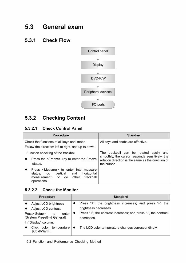
5-2 Function and Performance Checking Method
5.3 General exam
5.3.1 Check Flow
Control panel
Display
DVD-R/W
Peripheral devices
I/O ports
5.3.2 Checking Content
5.3.2.1 Check Control Panel Procedure Standard
Check the functions of all keys and knobs Follow the direction: left to right, and up to down.
All keys and knobs are effective.
Function checking of the trackball
Press the <Freeze> key to enter the Freeze status.
Press <Measure> to enter into measure status, do vertical and horizontal measurement, or do other trackball operations.
The trackball can be rotated easily and smoothly, the cursor responds sensitively, the rotation direction is the same as the direction of the cursor.
5.3.2.2 Check the Monitor Procedure Standard
Adjust LCD brightness Adjust LCD contrast Press<Setup> to enter [System Preset]→[ General], In “Display” column: Click color temperature
[Cold/Warm].
Press “+”, the brightness increases; and press “-”, the brightness decreases.
Press “+”, the contrast increases; and press “-”, the contrast decreases.
The LCD color temperature changes correspondingly.
Function and Performance Checking Method 5-3
Click [Load factory]. Display maintenance Log in as “Service”, click [Maintenance] in the Preset menu, then click [Test Main Monitor] to enter the monitor test.
Brightness/contrast return to the default setting. Click each functional button, the LCD responds correctly, the
standard is as follows: 1. Light-spot: 0; flash point: 0. 2. The adjoining dark dots are no more than 3 pairs, and there is
no adjoining dark dot in image area. 3. There is no adjoining dark dot of 3 or more than 3. 4. The dark dots are no more than 7 and those in the image
area are no more than 2 5. The distance between bad dots is no less than 5mm.
Note: image area refers to the rectangle when the background is black/white.
5.3.2.3 Check DVD-R/W Procedure Standard
DVD-R/W Drive Check if connection is normal Press 『F3』function key Perform DVD reading and writing.
The DVD-R/W driver can be ejected smoothly. Data reading and writing performs normally
without abnormal noise.
5.3.2.4 Check Peripheral Device Procedure Standard
Footswitch: Connect the footswitch and check the
functions of footswitch according to the functions listed in Key Config.
Press the freeze key (the right key), image is frozen, the freeze menu is displayed; press the key again, image is unfrozen.
Press the key (middle key), color printing starts Press the print key (left key),B/W printing starts
Video Printer: Check if the video printer and
ultrasound system are correctly connected. Then check the function of each key.
Press <Print> key, the printer begins to work, no image print deficiency or degradation. Switch video output port
Press <Print> key, the printer begins to work, the image printed has no deficiency or degradation.
Graph/ text Printer: Check if the graph/text printer and
ultrasound system are correctly connected. Then check the function of each key.
Press <Print> key, the printer begins to print, no print deficiency or degradation.
bar Code scanner: Perform code bar scanning when the ultrasound system is running normally.
The bar code is correctly displayed on the screen.
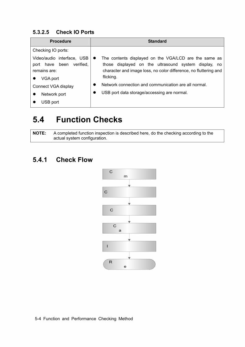
5-4 Function and Performance Checking Method
5.3.2.5 Check IO Ports Procedure Standard
Checking IO ports:
Video/audio interface, USB port have been verified, remains are:
VGA port
Connect VGA display
Network port
USB port
The contents displayed on the VGA/LCD are the same as those displayed on the ultrasound system display, no character and image loss, no color difference, no fluttering and flicking.
Network connection and communication are all normal.
USB port data storage/accessing are normal.
5.4 Function Checks NOTE: A completed function inspection is described here, do the checking according to the
actual system configuration.
5.4.1 Check Flow
C h e c k e a c h i m a g i n g m o d e
C h e c k t h e m e a s u r e m e n t s
C h e c k i n c i n e m o d e
C h e c k t h e p r o b e a p p l i c a t i o n
I m a g e & v i d e o m a n a g e
R e c o r d a n d s a v e t h e e x a m
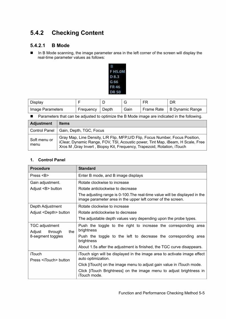
Function and Performance Checking Method 5-5
5.4.2 Checking Content
5.4.2.1 B Mode In B Mode scanning, the image parameter area in the left corner of the screen will display the
real-time parameter values as follows:
Display F D G FR DR
Image Parameters Frequency Depth Gain Frame Rate B Dynamic Range
Parameters that can be adjusted to optimize the B Mode image are indicated in the following.
Adjustment Items
Control Panel Gain, Depth, TGC, Focus
Soft menu or menu
Gray Map, Line Density, L/R Flip, MFP,U/D Flip, Focus Number, Focus Position, iClear, Dynamic Range, FOV, TSI, Acoustic power, Tint Map, iBeam, H Scale, Free Xros M ,Gray Invert , Biopsy Kit, Frequency, Trapezoid, Rotation, iTouch
1. Control Panel
Procedure Standard
Press <B> Enter B mode, and B image displays
Gain adjustment. Adjust <B> button
Rotate clockwise to increase Rotate anticlockwise to decrease The adjusting range is 0-100.The real-time value will be displayed in the image parameter area in the upper left corner of the screen.
Depth Adjustment Adjust <Depth> button
Rotate clockwise to increase Rotate anticlockwise to decrease The adjustable depth values vary depending upon the probe types.
TGC adjustment Adjust through the 8-segment toggles
Push the toggle to the right to increase the corresponding area brightness Push the toggle to the left to decrease the corresponding area brightness About 1.5s after the adjustment is finished, the TGC curve disappears.
iTouch Press <iTouch> button
iTouch sign will be displayed in the image area to activate image effect auto optimization. Click [iTouch] on the image menu to adjust gain value in iTouch mode. Click [iTouch Brightness] on the image menu to adjust brightness in iTouch mode.

5-6 Function and Performance Checking Method
2. Soft Menu or Menu Procedure Standard
Acoustic power B soft menu [A.power]
Rotate the multifunctional knob corresponding to [A.power] to adjust. AP value is displayed in real time in the upper part of the screen. You should perform exams according to actual situation and follow the ALARA Principle.
Frequency B soft menu [Frequency]
Rotate the multifunctional knob corresponding to [Frequency] to adjust: Rotate clockwise to increase. Rotate anticlockwise to decrease
Focus B soft menu [Focus Number]
Rotate the multifunctional knob corresponding to [Focus Number] to adjust: (B mode image has max. 4 focus ) The focus position symbol is displayed on the right side of the image.
Focus B soft menu [Focus Position]
Rotate the multifunctional knob corresponding to [Focus Position] to adjust: The focus position symbol is displayed on the right side of the image.
FOV (Field of View) B soft menu-> [FOV]
Rotate the multifunctional knob corresponding to [FOV] to adjust: The system provided four levels of scan range: W, N, M1, M2.
Dynamic Range B soft menu-> [Dynamic Range]
Rotate the multifunctional knob corresponding to [Dynamic Range] to adjust: the real time value will be displayed on the image parameter area in the upper left of the screen. As the dynamic range increases, the darker the image and the contrast, as well as the noise may increase.
Line Density B soft menu-> [Line Density]
Rotate the multifunctional knob corresponding to [Line Density] to adjust the parameter. There are four levels of line density available: UH/ H/ M/ L. The higher the line density, the higher the resolution, and the lower the frame rate.
iClear B soft menu-> [iClear]
Rotate the multifunctional knob corresponding to [iClear] to adjust: the bigger the value the stronger the effect. The bigger the value the more exquisite the image. The bigger the value the more outstanding the outline.
B soft menu-> [U/D Flip]/[L/R Flip]
Rotate the multifunctional knob corresponding to [U/D Flip]/[L/R Flip] to adjust.
Image Magnification Adjust <zoom> button
Rotate clockwise to zoom in the image (max. magnification factor is 10); rotate anticlockwise to zoom out the image. Roll the trackball to change position of the magnified image. Press <Zoom> in zoom status to exit the mode, the current window returns to the display before zoom.
Press <B>, and then
press Enter dual mode, and the right image is activated Press again to switch between the windows
Press <B> To enter single mode in dual window mode, or to exit from other modes.
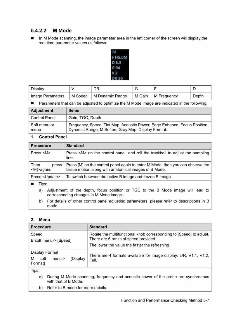
Function and Performance Checking Method 5-7
5.4.2.2 M Mode In M Mode scanning, the image parameter area in the left corner of the screen will display the
real-time parameter values as follows:
Display V DR G F D
Image Parameters M Speed M Dynamic Range M Gain M Frequency Depth
Parameters that can be adjusted to optimize the M Mode image are indicated in the following.
Adjustment Items
Control Panel Gain, TGC, Depth
Soft menu or menu
Frequency, Speed, Tint Map, Acoustic Power, Edge Enhance, Focus Position, Dynamic Range, M Soften, Gray Map, Display Format.
1. Control Panel
2. Menu Procedure Standard
Speed B soft menu-> [Speed]
Rotate the multifunctional knob corresponding to [Speed] to adjust. There are 6 ranks of speed provided. The lower the value the faster the refreshing.
Display Format M soft menu-> [Display Format]
There are 4 formats available for image display: L/R, V1:1, V1:2, Full.
Tips: a) During M Mode scanning, frequency and acoustic power of the probe are synchronous
with that of B Mode. b) Refer to B mode for more details.
Procedure Standard
Press <M> Press <M> on the control panel, and roll the trackball to adjust the sampling line.
Then press <M]>again.
Press [M] on the control panel again to enter M Mode, then you can observe the tissue motion along with anatomical images of B Mode.
Press <Update> To switch between the active B image and frozen B image.
Tips: a) Adjustment of the depth, focus position or TGC to the B Mode image will lead to
corresponding changes in M Mode image. b) For details of other control panel adjusting parameters, please refer to descriptions in B
mode

5-8 Function and Performance Checking Method
5.4.2.3 Color Mode In Color Mode scanning, the image parameter area in the left corner of the screen will display
the real-time parameter values as follows:
Display F G WF PRF
Image Parameters Frequency Color Gain Color Wall Filter Pulse Repetition Frequency
Parameters that can be adjusted to optimize the Color Mode image are indicated in the
following.
Adjustment Items
Control Panel Color Gain, Depth, Steer
Soft menu or menu
Caliper, Baseline, Invert, Priority , Packet Size, Persistence, Wall Filter, Color Map, Dual Live, B/C Align, Line Density, Speed Display, Smooth, Acoustic Power, Power Mode ,Frequency, Scale,
5.4.2.4 PW Mode In PW Mode scanning, the image parameter area in the left corner of the screen will display the
real-time parameter values as follows:
Display F G WF PRF SVD SV Angle
Image Parameters Frequency PW/CW
Gain Wall Filter
Pulse Repetition Frequency
Sample Volume Depth
Sample Volume
Size Angle
Parameters that can be adjusted to optimize the PW Mode image are indicated in the following.
Adjustment Items
Control Panel Gain
Soft menu or menu
Frequency, Speed, Acoustic Power ,Scale, Wall Filter, Duplex/Triplex, SV, Quick Angle, Angle, Invert, Baseline, Trace Area, T/F Res, Audio, Auto Calc, Auto Calc Cycle, Auto Calc Para, HPRF, Dynamic Range, Gray Map, Tint Map, Display Format
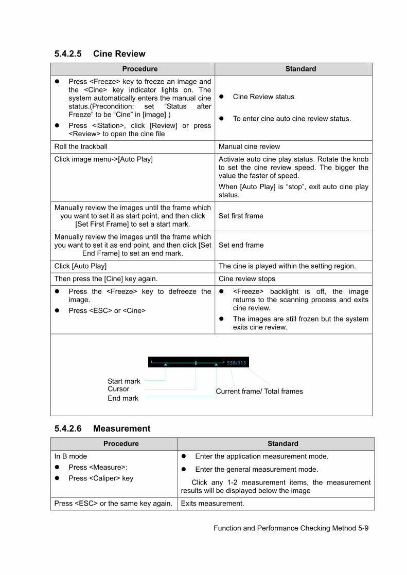
Function and Performance Checking Method 5-9
5.4.2.5 Cine Review Procedure Standard
Press <Freeze> key to freeze an image and the <Cine> key indicator lights on. The system automatically enters the manual cine status.(Precondition: set “Status after Freeze” to be “Cine” in [image] )
Press <iStation>, click [Review] or press <Review> to open the cine file
Cine Review status To enter cine auto cine review status.
Roll the trackball Manual cine review
Click image menu->[Auto Play] Activate auto cine play status. Rotate the knob to set the cine review speed. The bigger the value the faster of speed. When [Auto Play] is “stop”, exit auto cine play status.
Manually review the images until the frame which you want to set it as start point, and then click
[Set First Frame] to set a start mark. Set first frame
Manually review the images until the frame which you want to set it as end point, and then click [Set
End Frame] to set an end mark. Set end frame
Click [Auto Play] The cine is played within the setting region.
Then press the [Cine] key again. Cine review stops
Press the <Freeze> key to defreeze the image.
Press <ESC> or <Cine>
<Freeze> backlight is off, the image returns to the scanning process and exits cine review.
The images are still frozen but the system exits cine review.
5.4.2.6 Measurement Procedure Standard
In B mode Press <Measure>: Press <Caliper> key
Enter the application measurement mode.
Enter the general measurement mode.
Click any 1-2 measurement items, the measurement results will be displayed below the image
Press <ESC> or the same key again. Exits measurement.
Start mark
Cursor End mark
Current frame/ Total frames
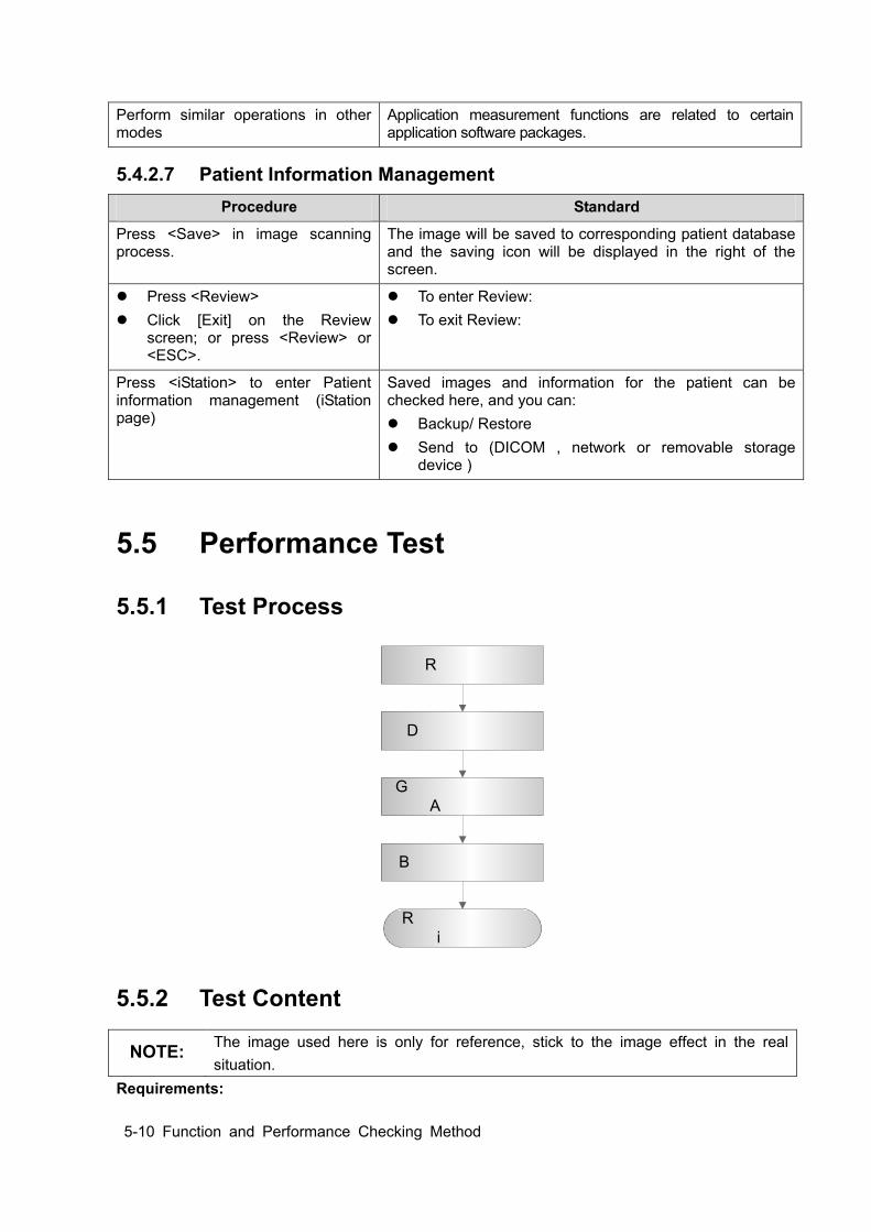
5-10 Function and Performance Checking Method
Perform similar operations in other modes
Application measurement functions are related to certain application software packages.
5.4.2.7 Patient Information Management Procedure Standard
Press <Save> in image scanning process.
The image will be saved to corresponding patient database and the saving icon will be displayed in the right of the screen.
Press <Review> Click [Exit] on the Review
screen; or press <Review> or <ESC>.
To enter Review: To exit Review:
Press <iStation> to enter Patient information management (iStation page)
Saved images and information for the patient can be checked here, and you can: Backup/ Restore Send to (DICOM , network or removable storage
device )
5.5 Performance Test
5.5.1 Test Process
R e s o l u t i o n
D e t e c t i o n d e p t h
G e o m e t r i c P o s i t i o n A c c u r a c y
B l a c k o u t a r e a t e s t
R e c o r d t h e e x a m i m a g e s
5.5.2 Test Content
NOTE: The image used here is only for reference, stick to the image effect in the real situation.
Requirements:
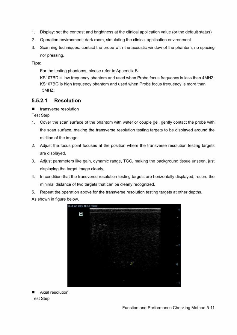
Function and Performance Checking Method 5-11
1. Display: set the contrast and brightness at the clinical application value (or the default status)
2. Operation environment: dark room, simulating the clinical application environment.
3. Scanning techniques: contact the probe with the acoustic window of the phantom, no spacing
nor pressing.
Tips:
For the testing phantoms, please refer to Appendix B.
KS107BD is low frequency phantom and used when Probe focus frequency is less than 4MHZ; KS107BG is high frequency phantom and used when Probe focus frequency is more than 5MHZ;
5.5.2.1 Resolution transverse resolution Test Step:
1. Cover the scan surface of the phantom with water or couple gel, gently contact the probe with
the scan surface, making the transverse resolution testing targets to be displayed around the
midline of the image.
2. Adjust the focus point focuses at the position where the transverse resolution testing targets
are displayed.
3. Adjust parameters like gain, dynamic range, TGC, making the background tissue unseen, just
displaying the target image clearly.
4. In condition that the transverse resolution testing targets are horizontally displayed, record the
minimal distance of two targets that can be clearly recognized.
5. Repeat the operation above for the transverse resolution testing targets at other depths.
As shown in figure below.
Axial resolution Test Step:

5-12 Function and Performance Checking Method
1. Cover the scan surface of the phantom with water or couple gel, gently contact the probe with
the scan surface, making the longitudinal resolution testing targets to be displayed around the
midline of the image.
2. Adjust the focus point focuses at the position where the longitudinal resolution testing targets
are displayed.
3. Adjust parameters like gain, dynamic range, TGC, making the background tissue unseen, just
displaying the target image clearly.
4. Record the minimal distance of two longitudinal resolution testing targets that can be clearly
recognized.
5. Repeat the operation above for the longitudinal resolution testing targets at other depths.
NOTE: 1. When using the convex probe, keep the transverse resolution testing targets to be displayed near the midline.
2. When using a linear probe with steer function, do not turn on the steer function when perform the transverse resolution test.
3. Zoom in the region where the targets located if necessary.
4. The diameter of the target point at a certain depth is equal to the transverse resolution at the depth.
5.5.2.2 Maximum Depth Test Step:
1. Cover the scan surface of the phantom with water or couple gel, gently contact the probe with
the scan surface
2. Set the system display depth according to the eXPcted maximum available depth of the probe
in use.
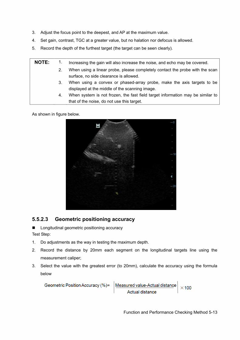
Function and Performance Checking Method 5-13
3. Adjust the focus point to the deepest, and AP at the maximum value.
4. Set gain, contrast, TGC at a greater value, but no halation nor defocus is allowed.
5. Record the depth of the furthest target (the target can be seen clearly).
NOTE: 1. Increasing the gain will also increase the noise, and echo may be covered.
2. When using a linear probe, please completely contact the probe with the scan surface, no side clearance is allowed.
3. When using a convex or phased-array probe, make the axis targets to be displayed at the middle of the scanning image.
4. When system is not frozen, the fast field target information may be similar to that of the noise, do not use this target.
As shown in figure below.
5.5.2.3 Geometric positioning accuracy Longitudinal geometric positioning accuracy Test Step:
1. Do adjustments as the way in testing the maximum depth.
2. Record the distance by 20mm each segment on the longitudinal targets line using the
measurement caliper;
3. Select the value with the greatest error (to 20mm), calculate the accuracy using the formula
below
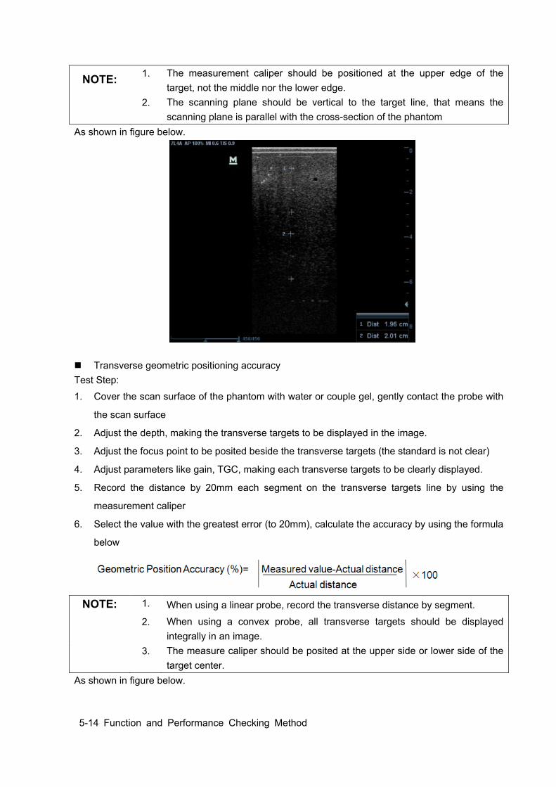
5-14 Function and Performance Checking Method
NOTE: 1. The measurement caliper should be positioned at the upper edge of the target, not the middle nor the lower edge.
2. The scanning plane should be vertical to the target line, that means the scanning plane is parallel with the cross-section of the phantom
As shown in figure below.
Transverse geometric positioning accuracy Test Step:
1. Cover the scan surface of the phantom with water or couple gel, gently contact the probe with
the scan surface
2. Adjust the depth, making the transverse targets to be displayed in the image.
3. Adjust the focus point to be posited beside the transverse targets (the standard is not clear)
4. Adjust parameters like gain, TGC, making each transverse targets to be clearly displayed.
5. Record the distance by 20mm each segment on the transverse targets line by using the
measurement caliper
6. Select the value with the greatest error (to 20mm), calculate the accuracy by using the formula
below
NOTE: 1. When using a linear probe, record the transverse distance by segment.
2. When using a convex probe, all transverse targets should be displayed integrally in an image.
3. The measure caliper should be posited at the upper side or lower side of the target center.
As shown in figure below.
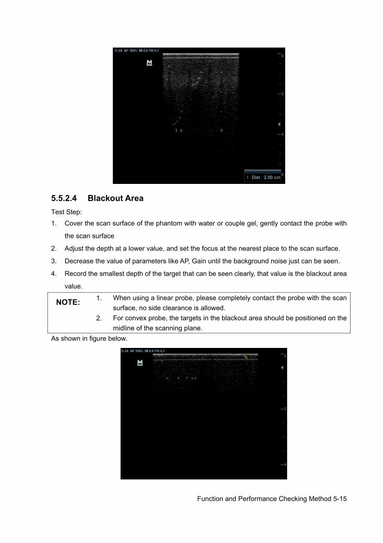
Function and Performance Checking Method 5-15
5.5.2.4 Blackout Area Test Step:
1. Cover the scan surface of the phantom with water or couple gel, gently contact the probe with
the scan surface
2. Adjust the depth at a lower value, and set the focus at the nearest place to the scan surface.
3. Decrease the value of parameters like AP, Gain until the background noise just can be seen.
4. Record the smallest depth of the target that can be seen clearly, that value is the blackout area
value.
NOTE: 1. When using a linear probe, please completely contact the probe with the scan surface, no side clearance is allowed.
2. For convex probe, the targets in the blackout area should be positioned on the midline of the scanning plane.
As shown in figure below.

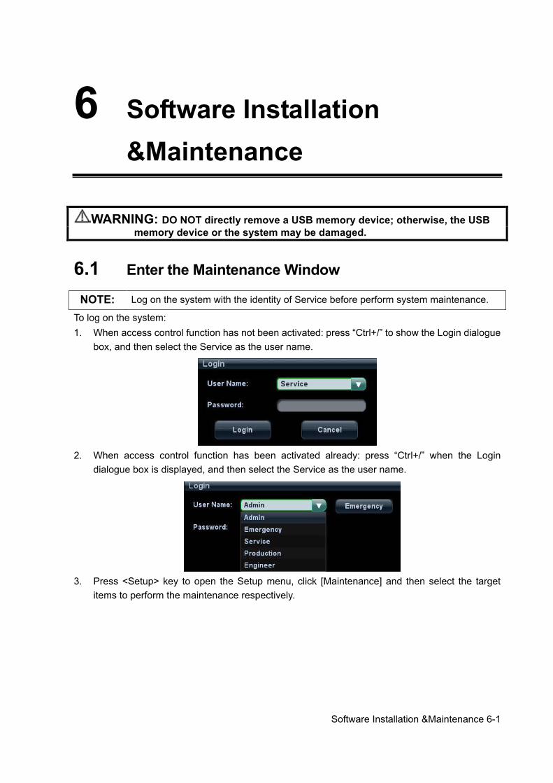
Software Installation &Maintenance 6-1
6 Software Installation &Maintenance
WARNING: DO NOT directly remove a USB memory device; otherwise, the USB memory device or the system may be damaged.
6.1 Enter the Maintenance Window NOTE: Log on the system with the identity of Service before perform system maintenance.
To log on the system: 1. When access control function has not been activated: press “Ctrl+/” to show the Login dialogue
box, and then select the Service as the user name.
2. When access control function has been activated already: press “Ctrl+/” when the Login
dialogue box is displayed, and then select the Service as the user name.
3. Press <Setup> key to open the Setup menu, click [Maintenance] and then select the target
items to perform the maintenance respectively.
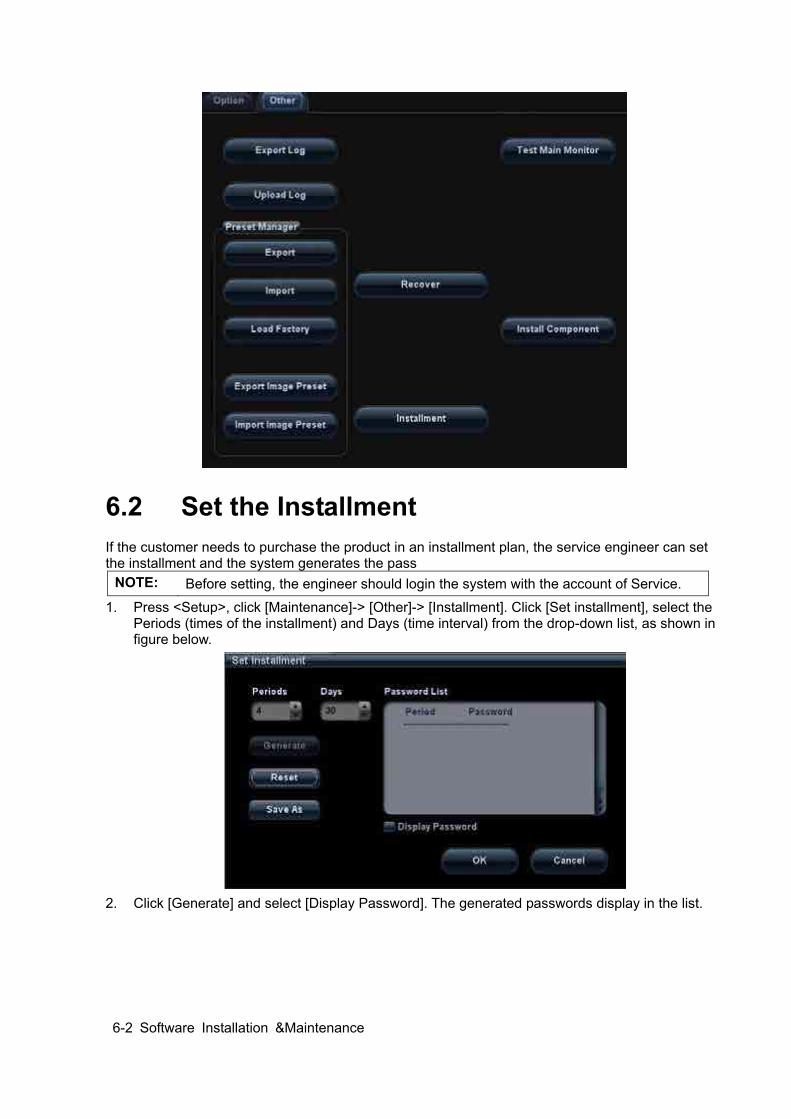
6-2 Software Installation &Maintenance
6.2 Set the Installment If the customer needs to purchase the product in an installment plan, the service engineer can set the installment and the system generates the pass
NOTE: Before setting, the engineer should login the system with the account of Service.
1. Press <Setup>, click [Maintenance]-> [Other]-> [Installment]. Click [Set installment], select the Periods (times of the installment) and Days (time interval) from the drop-down list, as shown in figure below.
2. Click [Generate] and select [Display Password]. The generated passwords display in the list.
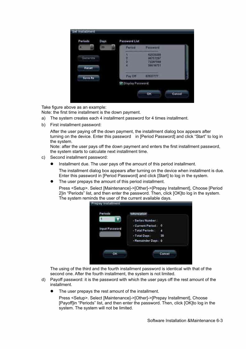
Software Installation &Maintenance 6-3
Take figure above as an example: Note: the first time installment is the down payment. a) The system creates each 4 installment password for 4 times installment. b) First installment password:
After the user paying off the down payment, the installment dialog box appears after turning on the device. Enter this password in [Period Password] and click “Start” to log in the system. Note: after the user pays off the down payment and enters the first installment password, the system starts to calculate next installment time.
c) Second installment password: Installment due. The user pays off the amount of this period installment.
The installment dialog box appears after turning on the device when installment is due. Enter this password in [Period Password] and click [Start] to log in the system.
The user prepays the amount of this period installment. Press <Setup>. Select [Maintenance]->[Other]->[Prepay Installment], Choose [Period 2]in “Periods” list, and then enter the password. Then, click [OK]to log in the system. The system reminds the user of the current available days.
The using of the third and the fourth installment password is identical with that of the second one. After the fourth installment, the system is not limited.
d) Payoff password: it is the password with which the user pays off the rest amount of the installment. The user prepays the rest amount of the installment.
Press <Setup>. Select [Maintenance]->[Other]->[Prepay Installment], Choose [Payoff]in “Periods” list, and then enter the password. Then, click [OK]to log in the system. The system will not be limited.
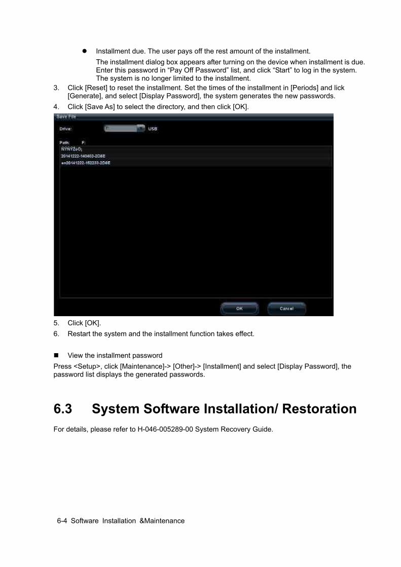
6-4 Software Installation &Maintenance
Installment due. The user pays off the rest amount of the installment. The installment dialog box appears after turning on the device when installment is due. Enter this password in “Pay Off Password” list, and click “Start” to log in the system. The system is no longer limited to the installment.
3. Click [Reset] to reset the installment. Set the times of the installment in [Periods] and lick [Generate], and select [Display Password], the system generates the new passwords.
4. Click [Save As] to select the directory, and then click [OK].
5. Click [OK]. 6. Restart the system and the installment function takes effect. View the installment password Press <Setup>, click [Maintenance]-> [Other]-> [Installment] and select [Display Password], the password list displays the generated passwords.
6.3 System Software Installation/ Restoration For details, please refer to H-046-005289-00 System Recovery Guide.
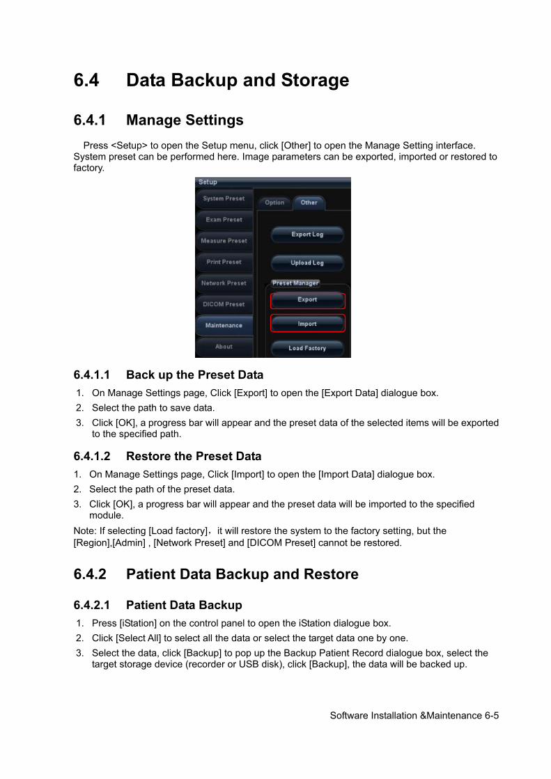
Software Installation &Maintenance 6-5
6.4 Data Backup and Storage
6.4.1 Manage Settings Press <Setup> to open the Setup menu, click [Other] to open the Manage Setting interface. System preset can be performed here. Image parameters can be exported, imported or restored to factory.
6.4.1.1 Back up the Preset Data 1. On Manage Settings page, Click [Export] to open the [Export Data] dialogue box. 2. Select the path to save data. 3. Click [OK], a progress bar will appear and the preset data of the selected items will be exported
to the specified path.
6.4.1.2 Restore the Preset Data 1. On Manage Settings page, Click [Import] to open the [Import Data] dialogue box. 2. Select the path of the preset data. 3. Click [OK], a progress bar will appear and the preset data will be imported to the specified
module. Note: If selecting [Load factory],it will restore the system to the factory setting, but the [Region],[Admin] , [Network Preset] and [DICOM Preset] cannot be restored.
6.4.2 Patient Data Backup and Restore
6.4.2.1 Patient Data Backup 1. Press [iStation] on the control panel to open the iStation dialogue box. 2. Click [Select All] to select all the data or select the target data one by one. 3. Select the data, click [Backup] to pop up the Backup Patient Record dialogue box, select the
target storage device (recorder or USB disk), click [Backup], the data will be backed up.
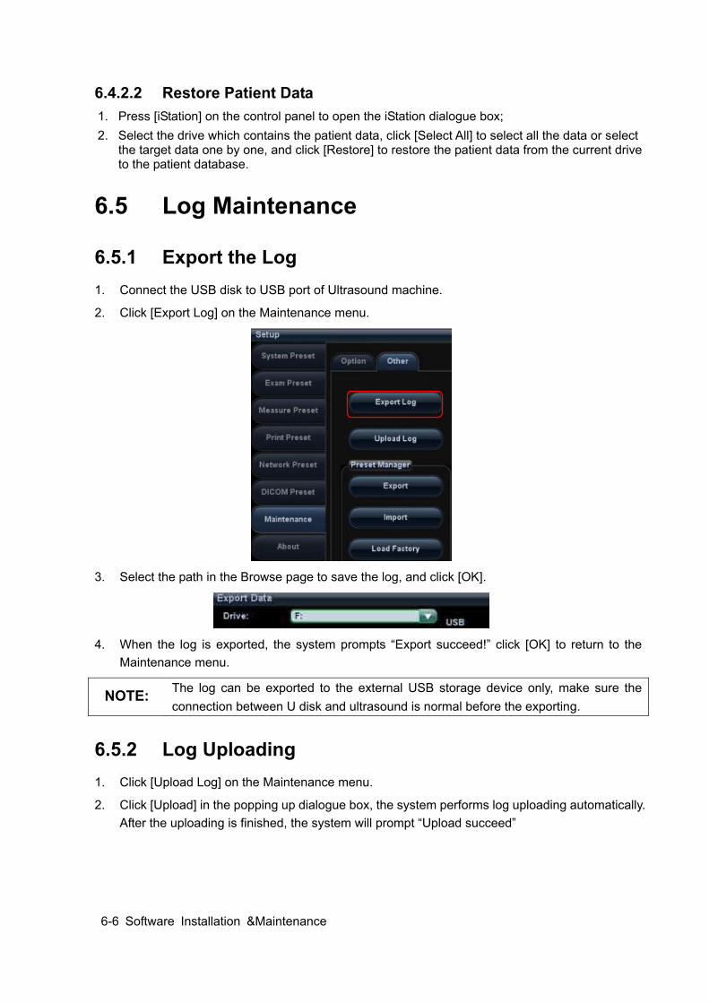
6-6 Software Installation &Maintenance
6.4.2.2 Restore Patient Data 1. Press [iStation] on the control panel to open the iStation dialogue box; 2. Select the drive which contains the patient data, click [Select All] to select all the data or select
the target data one by one, and click [Restore] to restore the patient data from the current drive to the patient database.
6.5 Log Maintenance
6.5.1 Export the Log 1. Connect the USB disk to USB port of Ultrasound machine.
2. Click [Export Log] on the Maintenance menu.
3. Select the path in the Browse page to save the log, and click [OK].
4. When the log is exported, the system prompts “Export succeed!” click [OK] to return to the
Maintenance menu.
NOTE: The log can be exported to the external USB storage device only, make sure the connection between U disk and ultrasound is normal before the exporting.
6.5.2 Log Uploading 1. Click [Upload Log] on the Maintenance menu.
2. Click [Upload] in the popping up dialogue box, the system performs log uploading automatically. After the uploading is finished, the system will prompt “Upload succeed”
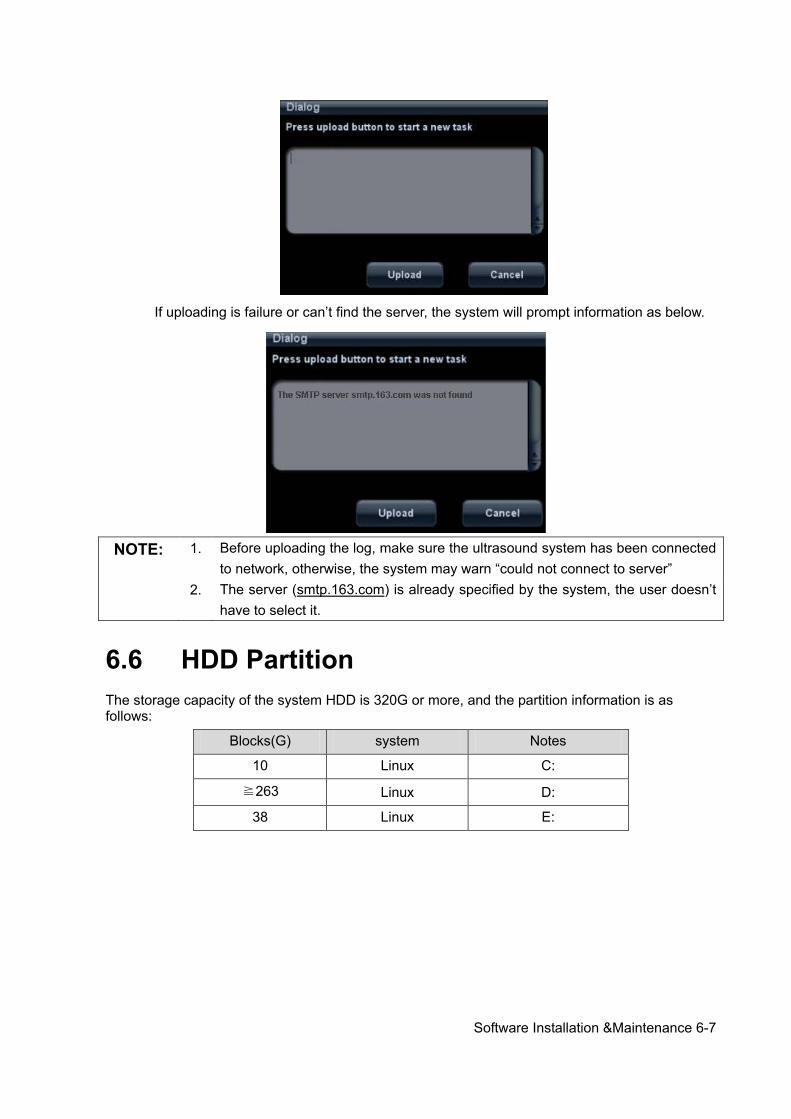
Software Installation &Maintenance 6-7
If uploading is failure or can’t find the server, the system will prompt information as below.
NOTE: 1. Before uploading the log, make sure the ultrasound system has been connected
to network, otherwise, the system may warn “could not connect to server”
2. The server (smtp.163.com) is already specified by the system, the user doesn’t have to select it.
6.6 HDD Partition The storage capacity of the system HDD is 320G or more, and the partition information is as follows:
Blocks(G) system Notes
10 Linux C:
≧263 Linux D:
38 Linux E:
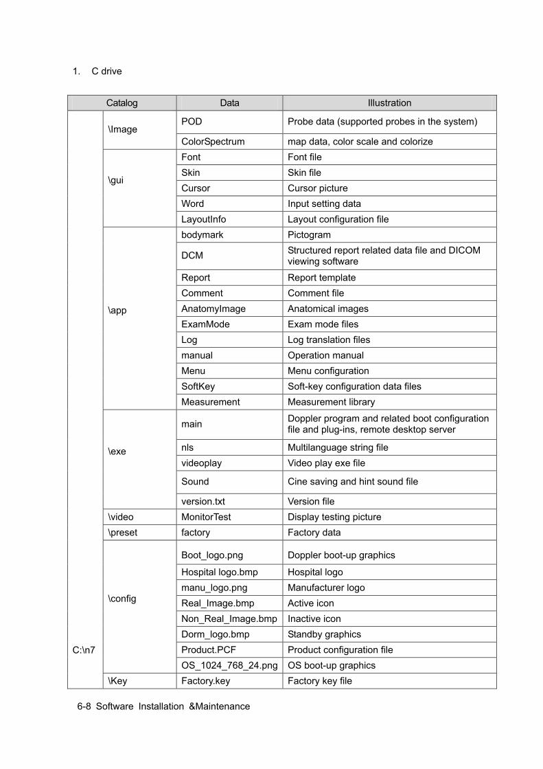
6-8 Software Installation &Maintenance
1. C drive
Catalog Data Illustration
C:\n7
\Image POD Probe data (supported probes in the system)
ColorSpectrum map data, color scale and colorize
\gui
Font Font file Skin Skin file Cursor Cursor picture Word Input setting data LayoutInfo Layout configuration file
\app
bodymark Pictogram
DCM Structured report related data file and DICOM viewing software
Report Report template Comment Comment file AnatomyImage Anatomical images ExamMode Exam mode files Log Log translation files manual Operation manual Menu Menu configuration SoftKey Soft-key configuration data files Measurement Measurement library
\exe
main Doppler program and related boot configuration file and plug-ins, remote desktop server
nls Multilanguage string file videoplay Video play exe file
Sound Cine saving and hint sound file
version.txt Version file \video MonitorTest Display testing picture \preset factory Factory data
\config
Boot_logo.png Doppler boot-up graphics
Hospital logo.bmp Hospital logo manu_logo.png Manufacturer logo Real_Image.bmp Active icon Non_Real_Image.bmp Inactive icon
Dorm_logo.bmp Standby graphics Product.PCF Product configuration file OS_1024_768_24.png OS boot-up graphics
\Key Factory.key Factory key file
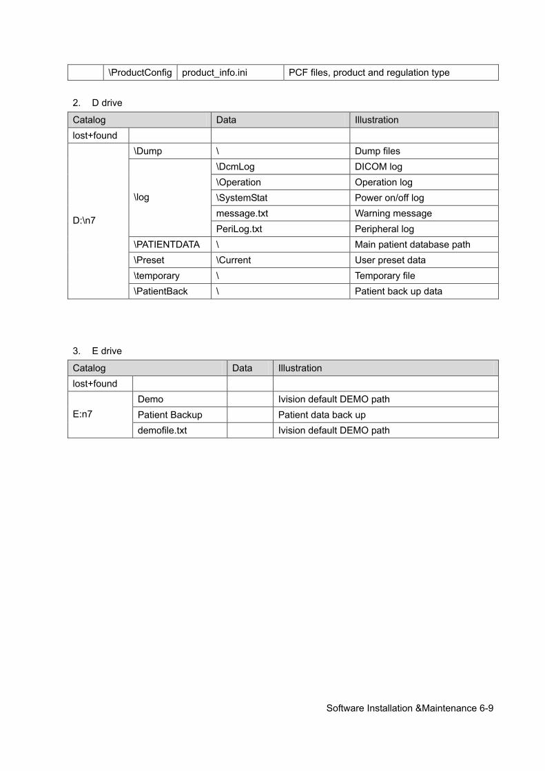
Software Installation &Maintenance 6-9
\ProductConfig product_info.ini PCF files, product and regulation type 2. D drive
Catalog Data Illustration lost+found
D:\n7
\Dump \ Dump files
\log
\DcmLog DICOM log \Operation Operation log \SystemStat Power on/off log message.txt Warning message PeriLog.txt Peripheral log
\PATIENTDATA \ Main patient database path \Preset \Current User preset data \temporary \ Temporary file \PatientBack \ Patient back up data
3. E drive
Catalog Data Illustration lost+found
E:n7 Demo Ivision default DEMO path Patient Backup Patient data back up demofile.txt Ivision default DEMO path

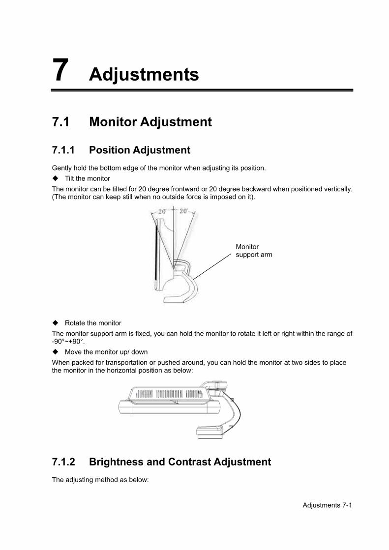
Adjustments 7-1
7 Adjustments
7.1 Monitor Adjustment
7.1.1 Position Adjustment Gently hold the bottom edge of the monitor when adjusting its position. Tilt the monitor The monitor can be tilted for 20 degree frontward or 20 degree backward when positioned vertically. (The monitor can keep still when no outside force is imposed on it).
Rotate the monitor The monitor support arm is fixed, you can hold the monitor to rotate it left or right within the range of -90°~+90°. Move the monitor up/ down When packed for transportation or pushed around, you can hold the monitor at two sides to place the monitor in the horizontal position as below:
7.1.2 Brightness and Contrast Adjustment The adjusting method as below:
Monitor support arm
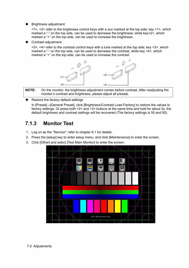
7-2 Adjustments
Brightness adjustment: <1>, <2> refer to the brightness control keys with a sun marked at the top side; key <1>, which marked a “-” on the top side, can be used to decrease the brightness; while key<2>, which marked a “+” on the top side, can be used to increase the brightness.
Contrast adjustment: <3>, <4> refer to the contrast control keys with a lune marked at the top side; key <3>, which marked a “-” on the top side, can be used to decrease the contrast, while key <4>, which marked a “+” on the top side, can be used to increase the contrast.
NOTE: On the monitor, the brightness adjustment comes before contrast. After readjusting the
monitor’s contrast and brightness, please adjust all presets.
Restore the factory default settings In [Preset]→[General Preset], click [Brightness/Contrast Load Factory] to restore the values to factory settings. Or press both <2> and <3> buttons at the same time and hold for about 3s, the default brightness and contrast settings will be recovered (The factory settings is 50 and 50).
7.1.3 Monitor Test 1. Log on as the "Service"; refer to chapter 6.1 for details. 2. Press the [setup] key to enter setup menu, and click [Maintenance] to enter the screen. 3. Click [Other] and select [Test Main Monitor] to enter the screen:
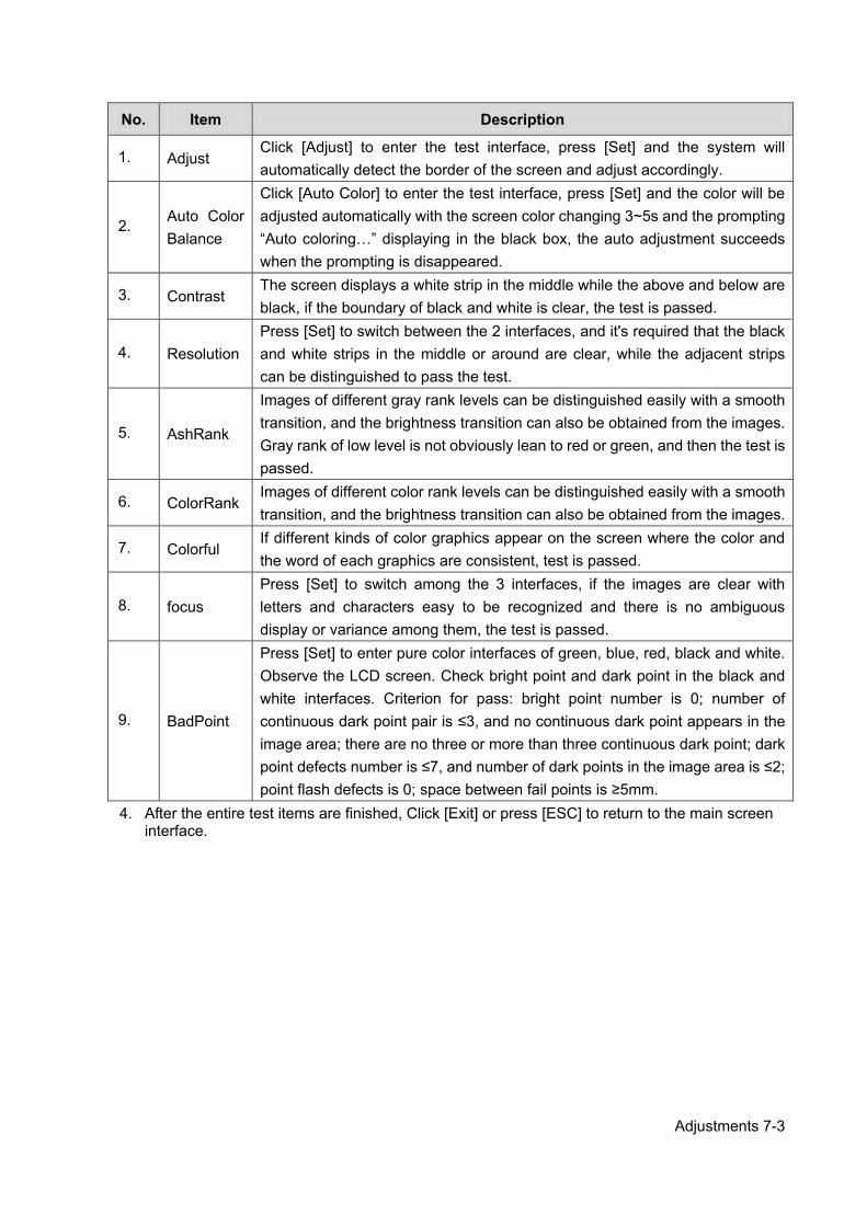
Adjustments 7-3
No. Item Description
1. Adjust Click [Adjust] to enter the test interface, press [Set] and the system will automatically detect the border of the screen and adjust accordingly.
2. Auto Color Balance
Click [Auto Color] to enter the test interface, press [Set] and the color will be adjusted automatically with the screen color changing 3~5s and the prompting “Auto coloring…” displaying in the black box, the auto adjustment succeeds when the prompting is disappeared.
3. Contrast The screen displays a white strip in the middle while the above and below are black, if the boundary of black and white is clear, the test is passed.
4. Resolution Press [Set] to switch between the 2 interfaces, and it's required that the black and white strips in the middle or around are clear, while the adjacent strips can be distinguished to pass the test.
5. AshRank
Images of different gray rank levels can be distinguished easily with a smooth transition, and the brightness transition can also be obtained from the images. Gray rank of low level is not obviously lean to red or green, and then the test is passed.
6. ColorRank Images of different color rank levels can be distinguished easily with a smooth transition, and the brightness transition can also be obtained from the images.
7. Colorful If different kinds of color graphics appear on the screen where the color and the word of each graphics are consistent, test is passed.
8. focus Press [Set] to switch among the 3 interfaces, if the images are clear with letters and characters easy to be recognized and there is no ambiguous display or variance among them, the test is passed.
9. BadPoint
Press [Set] to enter pure color interfaces of green, blue, red, black and white. Observe the LCD screen. Check bright point and dark point in the black and white interfaces. Criterion for pass: bright point number is 0; number of continuous dark point pair is ≤3, and no continuous dark point appears in the image area; there are no three or more than three continuous dark point; dark point defects number is ≤7, and number of dark points in the image area is ≤2; point flash defects is 0; space between fail points is ≥5mm.
4. After the entire test items are finished, Click [Exit] or press [ESC] to return to the main screen interface.
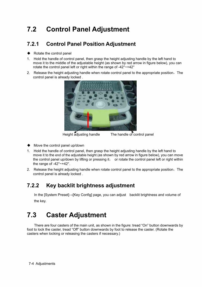
7-4 Adjustments
7.2 Control Panel Adjustment
7.2.1 Control Panel Position Adjustment Rotate the control panel 1. Hold the handle of control panel, then grasp the height adjusting handle by the left hand to
move it to the middle of the adjustable height (as shown by red arrow in figure below), you can rotate the control panel left or right within the range of -42°~+42°
2. Release the height adjusting handle when rotate control panel to the appropriate position,The control panel is already locked .
Height adjusting handle The handle of control panel Move the control panel up/down 1. Hold the handle of control panel, then grasp the height adjusting handle by the left hand to
move it to the end of the adjustable height (as shown by red arrow in figure below), you can move the control panel up/down by lifting or pressing it, or rotate the control panel left or right within the range of -42°~+42°.
2. Release the height adjusting handle when rotate control panel to the appropriate position,The control panel is already locked .
7.2.2 Key backlit brightness adjustment In the [System Preset]→[Key Config] page, you can adjust backlit brightness and volume of
the key.
7.3 Caster Adjustment There are four casters of the main unit, as shown in the figure: tread “On” button downwards by
foot to lock the caster, tread “Off” button downwards by foot to release the caster. (Rotate the casters when locking or releasing the casters if necessary.)

Adjustments 7-5
LOCKING RELEASING

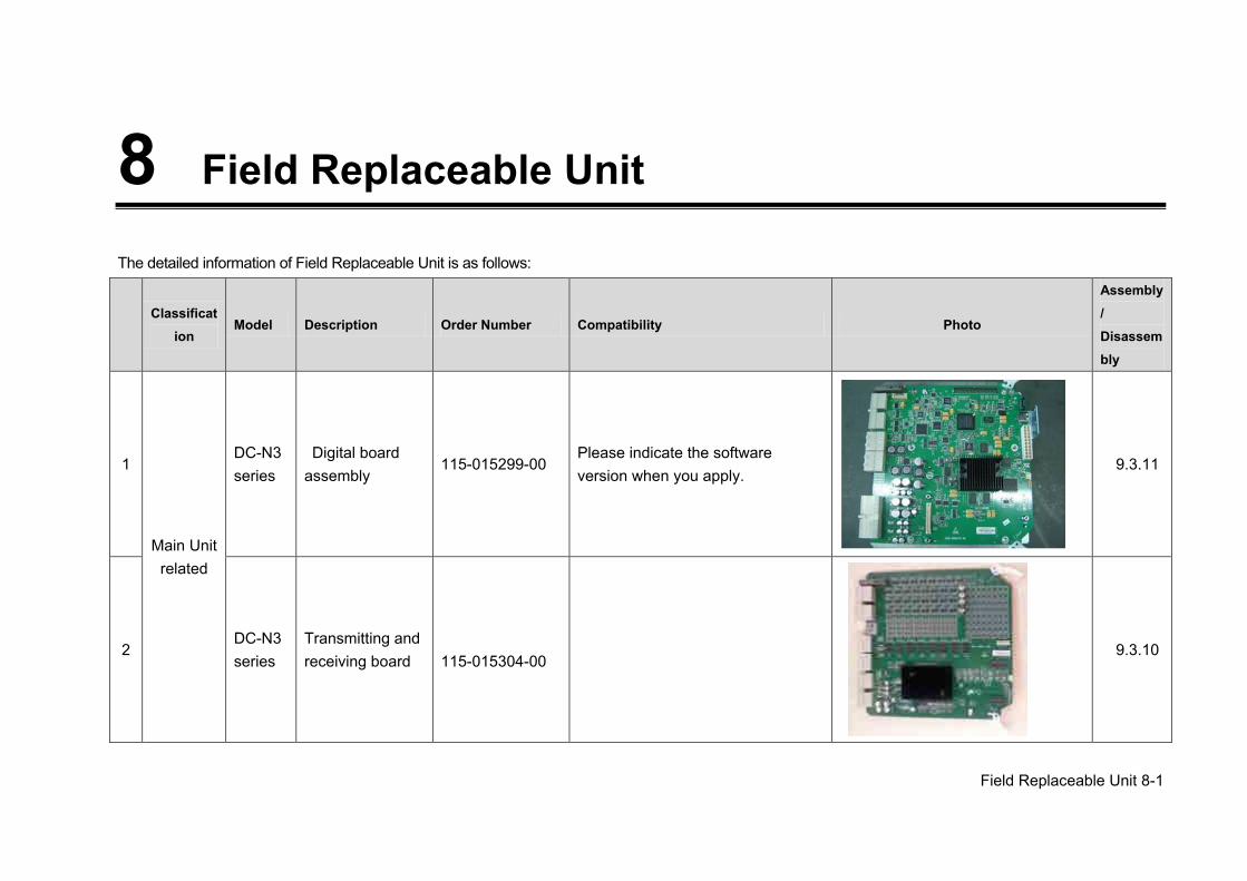
Field Replaceable Unit 8-1
8 Field Replaceable Unit
The detailed information of Field Replaceable Unit is as follows:
Classificat
ion Model Description Order Number Compatibility Photo
Assembly/ Disassembly
1
Main Unit related
DC-N3 series
Digital board assembly
115-015299-00 Please indicate the software version when you apply.
9.3.11
2 DC-N3 series
Transmitting and receiving board
115-015304-00
9.3.10
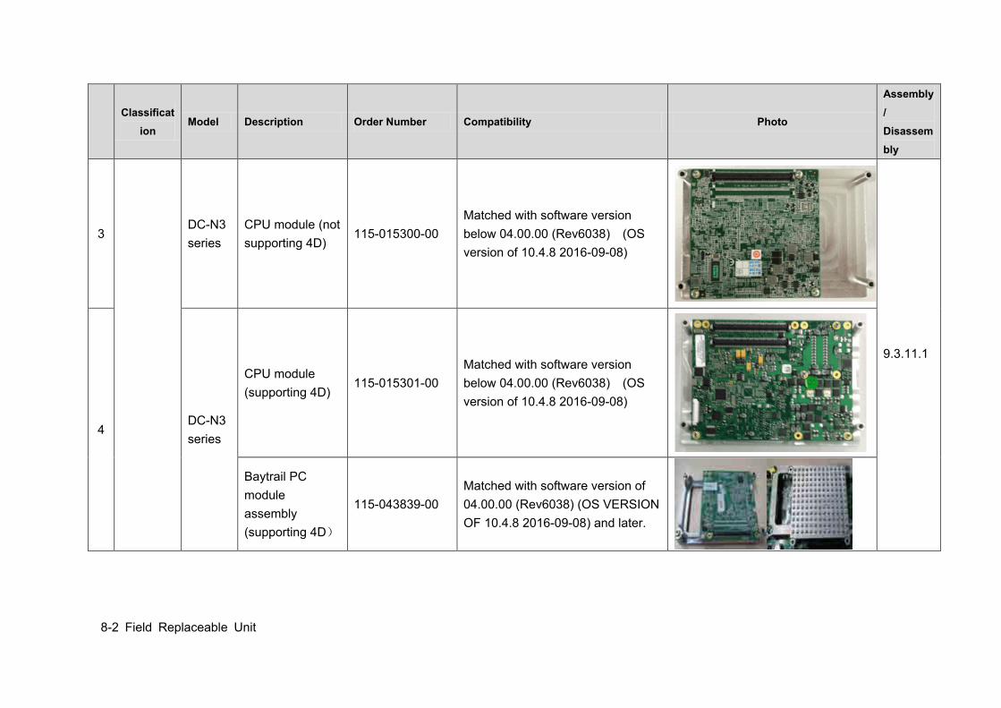
8-2 Field Replaceable Unit
Classificat
ion Model Description Order Number Compatibility Photo
Assembly/ Disassembly
3 DC-N3 series
CPU module (not supporting 4D)
115-015300-00 Matched with software version below 04.00.00 (Rev6038) (OS version of 10.4.8 2016-09-08)
9.3.11.1
4 DC-N3 series
CPU module (supporting 4D)
115-015301-00 Matched with software version below 04.00.00 (Rev6038) (OS version of 10.4.8 2016-09-08)
Baytrail PC module assembly (supporting 4D)
115-043839-00 Matched with software version of 04.00.00 (Rev6038) (OS VERSION OF 10.4.8 2016-09-08) and later.
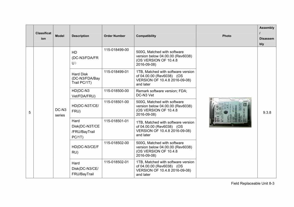
Field Replaceable Unit 8-3
Classificat
ion Model Description Order Number Compatibility Photo
Assembly/ Disassembly
5 DC-N3 series
HD (DC-N3/FDA/FRU)
115-018499-00 500G, Matched with software version below 04.00.00 (Rev6038) (OS VERSION OF 10.4.8 2016-09-08)
9.3.8
Hard Disk (DC-N3/FDA/BayTrail PC/1T)
115-018499-01 1TB, Matched with software version of 04.00.00 (Rev6038) (OS VERSION OF 10.4.8 2016-09-08) and later
HD(DC-N3 Vet/FDA/FRU)
115-018500-00 Remark software version; FDA; DC-N3 Vet
HD(DC-N3T/CE/FRU)
115-018501-00 500G, Matched with software version below 04.00.00 (Rev6038) (OS VERSION OF 10.4.8 2016-09-08)
Hard Disk(DC-N3T/CE/FRU/BayTrail PC/1T)
115-018501-01 1TB, Matched with software version of 04.00.00 (Rev6038) (OS VERSION OF 10.4.8 2016-09-08) and later
HD(DC-N3/CE/FRU)
115-018502-00 500G, Matched with software version below 04.00.00 (Rev6038) (OS VERSION OF 10.4.8 2016-09-08)
Hard Disk(DC-N3/CE/FRU/BayTrail
115-018502-01 1TB, Matched with software version of 04.00.00 (Rev6038) (OS VERSION OF 10.4.8 2016-09-08) and later
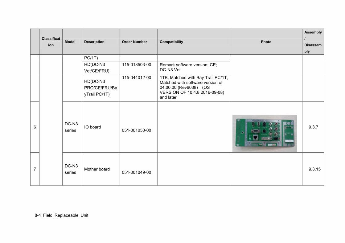
8-4 Field Replaceable Unit
Classificat
ion Model Description Order Number Compatibility Photo
Assembly/ Disassembly
PC/1T) HD(DC-N3 Vet/CE/FRU)
115-018503-00 Remark software version; CE; DC-N3 Vet
HD(DC-N3 PRO/CE/FRU/BayTrail PC/1T)
115-044012-00 1TB, Matched with Bay Trail PC/1T, Matched with software version of 04.00.00 (Rev6038) (OS VERSION OF 10.4.8 2016-09-08) and later
6 DC-N3 series
IO board
051-001050-00
9.3.7
7 DC-N3 series
Mother board
051-001049-00 9.3.15
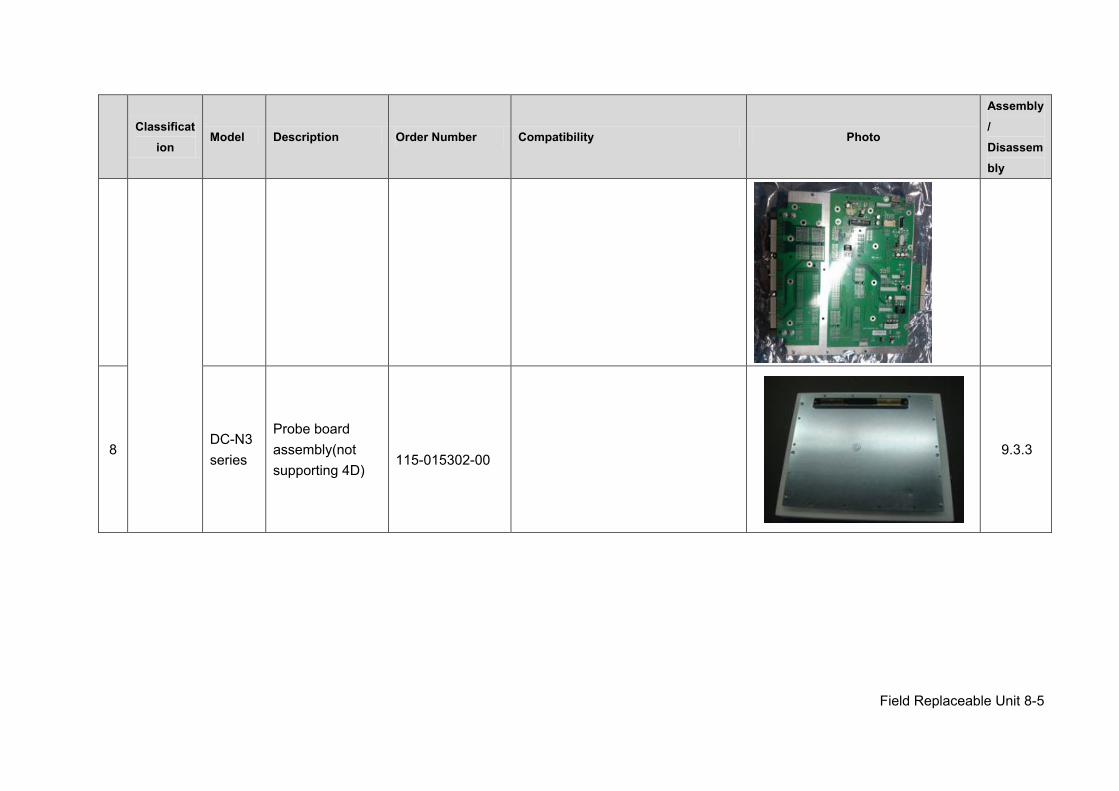
Field Replaceable Unit 8-5
Classificat
ion Model Description Order Number Compatibility Photo
Assembly/ Disassembly
8 DC-N3 series
Probe board assembly(not supporting 4D)
115-015302-00
9.3.3
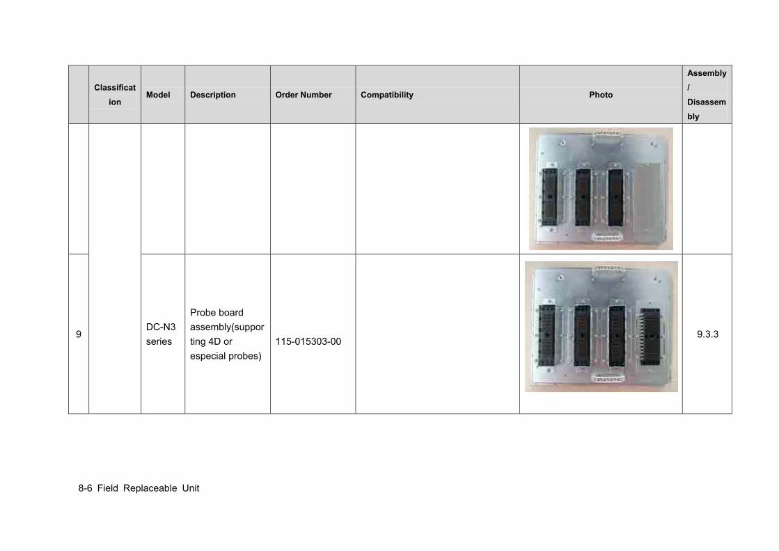
8-6 Field Replaceable Unit
Classificat
ion Model Description Order Number Compatibility Photo
Assembly/ Disassembly
9 DC-N3 series
Probe board assembly(supporting 4D or especial probes)
115-015303-00
9.3.3
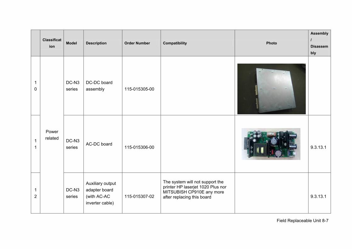
Field Replaceable Unit 8-7
Classificat
ion Model Description Order Number Compatibility Photo
Assembly/ Disassembly
10
Power related
DC-N3 series
DC-DC board assembly
115-015305-00
11
DC-N3 series
AC-DC board
115-015306-00
9.3.13.1
12
DC-N3 series
Auxiliary output adapter board (with AC-AC inverter cable)
115-015307-02
The system will not support the printer HP laserjet 1020 Plus nor MITSUBISH CP910E any more after replacing this board
9.3.13.1
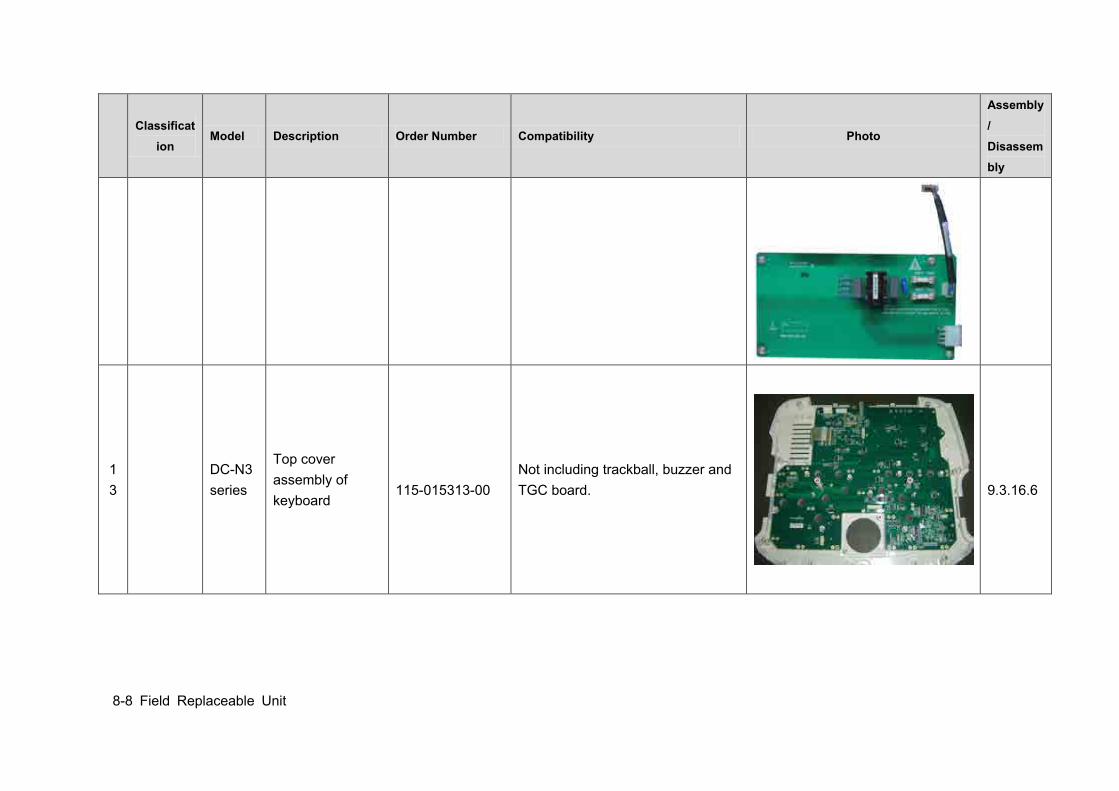
8-8 Field Replaceable Unit
Classificat
ion Model Description Order Number Compatibility Photo
Assembly/ Disassembly
13
DC-N3 series
Top cover assembly of keyboard
115-015313-00 Not including trackball, buzzer and TGC board.
9.3.16.6
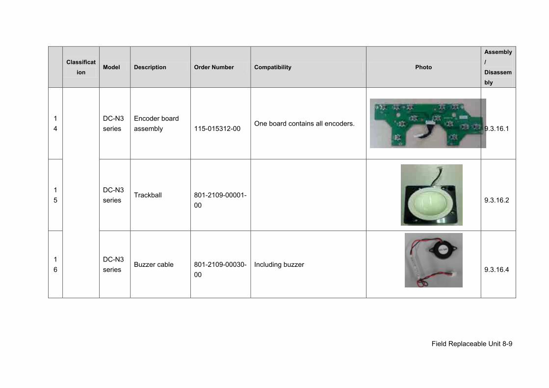
Field Replaceable Unit 8-9
Classificat
ion Model Description Order Number Compatibility Photo
Assembly/ Disassembly
14
DC-N3 series
Encoder board assembly
115-015312-00 One board contains all encoders.
9.3.16.1
15
DC-N3 series
Trackball
801-2109-00001-00
9.3.16.2
16
DC-N3 series
Buzzer cable
801-2109-00030-00
Including buzzer
9.3.16.4
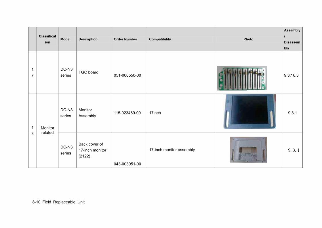
8-10 Field Replaceable Unit
Classificat
ion Model Description Order Number Compatibility Photo
Assembly/ Disassembly
17
DC-N3 series
TGC board
051-000550-00
9.3.16.3
18
Monitor related
DC-N3 series
Monitor Assembly
115-023469-00 17inch
9.3.1
DC-N3 series
Back cover of 17-inch monitor (2122)
043-003951-00
17-inch monitor assembly
9.3.1
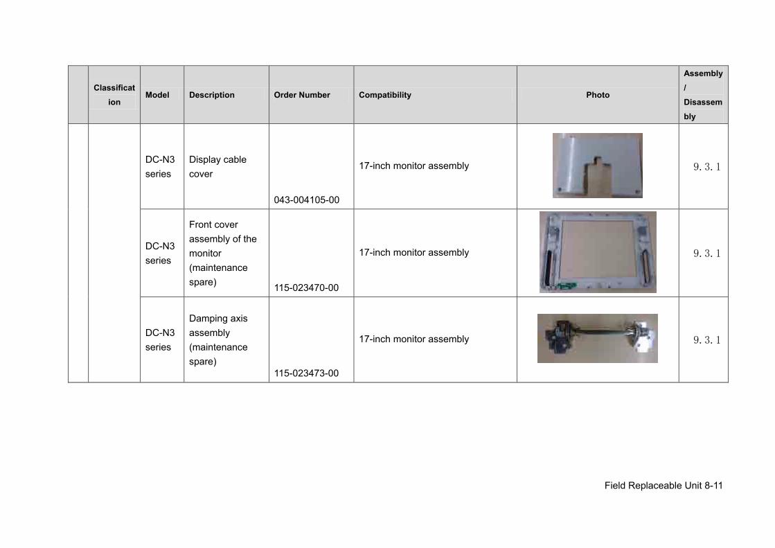
Field Replaceable Unit 8-11
Classificat
ion Model Description Order Number Compatibility Photo
Assembly/ Disassembly
DC-N3 series
Display cable cover
043-004105-00
17-inch monitor assembly
9.3.1
DC-N3 series
Front cover assembly of the monitor (maintenance spare) 115-023470-00
17-inch monitor assembly
9.3.1
DC-N3 series
Damping axis assembly (maintenance spare)
115-023473-00
17-inch monitor assembly
9.3.1
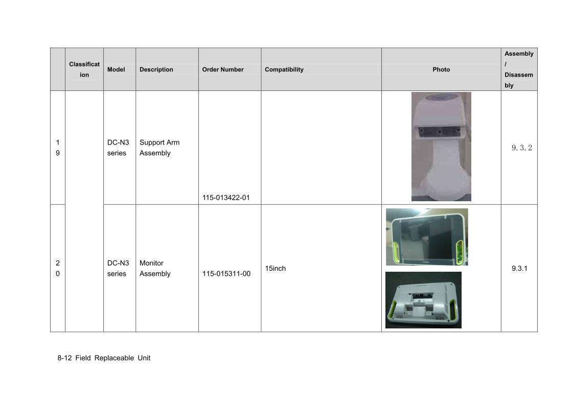
8-12 Field Replaceable Unit
Classificat
ion Model Description Order Number Compatibility Photo
Assembly/ Disassembly
19
DC-N3 series
Support Arm Assembly
115-013422-01
9.3.2
20
DC-N3 series
Monitor Assembly
115-015311-00 15inch
9.3.1
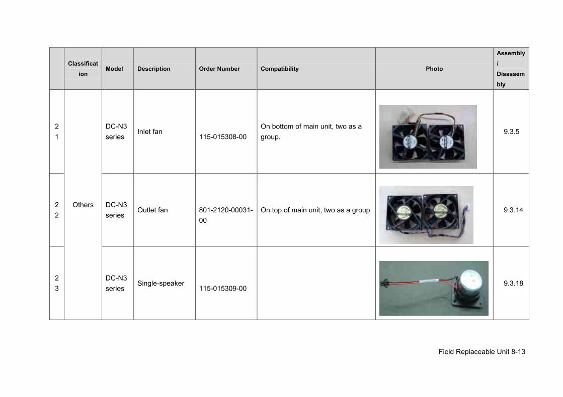
Field Replaceable Unit 8-13
Classificat
ion Model Description Order Number Compatibility Photo
Assembly/ Disassembly
21
Others
DC-N3 series
Inlet fan
115-015308-00 On bottom of main unit, two as a group.
9.3.5
22
DC-N3 series
Outlet fan
801-2120-00031-00
On top of main unit, two as a group.
9.3.14
23
DC-N3 series
Single-speaker
115-015309-00
9.3.18
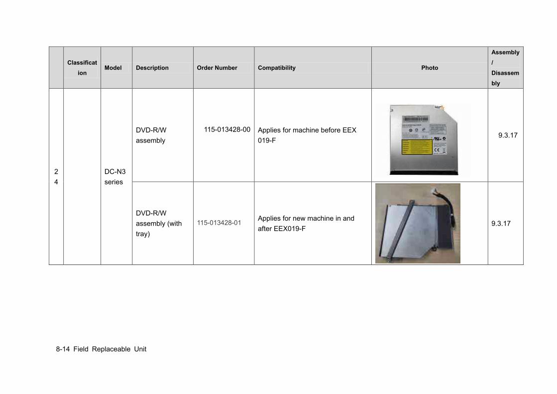
8-14 Field Replaceable Unit
Classificat
ion Model Description Order Number Compatibility Photo
Assembly/ Disassembly
24
DC-N3 series
DVD-R/W assembly
115-013428-00
Applies for machine before EEX 019-F
9.3.17
DVD-R/W assembly (with tray)
115-013428-01 Applies for new machine in and after EEX019-F
9.3.17
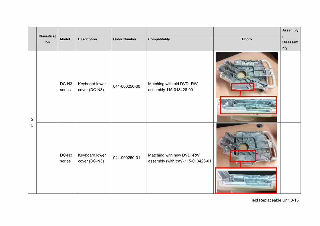
Field Replaceable Unit 8-15
Classificat
ion Model Description Order Number Compatibility Photo
Assembly/ Disassembly
25
DC-N3 series
Keyboard lower cover (DC-N3)
044-000250-00 Matching with old DVD -RW assembly 115-013428-00
DC-N3 series
Keyboard lower cover (DC-N3)
044-000250-01 Matching with new DVD -RW assembly (with tray) 115-013428-01
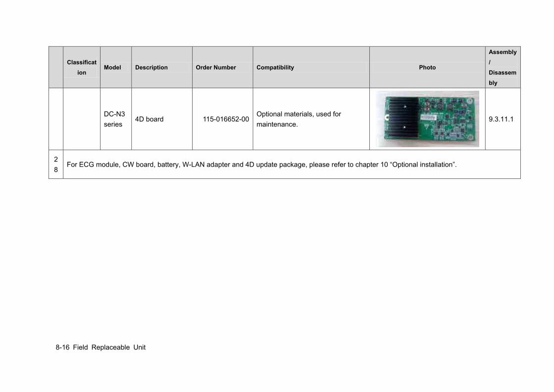
8-16 Field Replaceable Unit
Classificat
ion Model Description Order Number Compatibility Photo
Assembly/ Disassembly
DC-N3 series
4D board 115-016652-00 Optional materials, used for maintenance.
9.3.11.1
28
For ECG module, CW board, battery, W-LAN adapter and 4D update package, please refer to chapter 10 “Optional installation”.

Structure and Assembly/Disassembly 9-1
9 Structure and Assembly/Disassembly
9.1 Structure of the Whole System
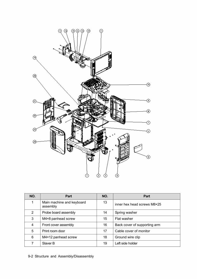
9-2 Structure and Assembly/Disassembly
NO. Part NO. Part
1 Main machine and keyboard assembly
13 inner hex head screws M8×25
2 Probe board assembly 14 Spring washer
3 M4×8 panhead screw 15 Flat washer
4 Front cover assembly 16 Back cover of supporting arm
5 Print room door 17 Cable cover of monitor
6 M4×12 panhead screw 18 Ground wire clip
7 Slaver B 19 Left side holder
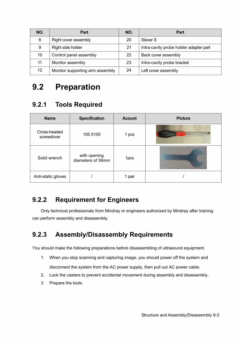
Structure and Assembly/Disassembly 9-3
NO. Part NO. Part
8 Right cover assembly 20 Slaver S
9 Right side holder 21 Intra-cavity probe holder adapter part
10 Control panel assembly 22 Back cover assembly
11 Monitor assembly 23 Intra-cavity probe bracket
12 Monitor supporting arm assembly 24 Left cover assembly
9.2 Preparation
9.2.1 Tools Required
Name Specification Acount Picture
Cross-headed screwdriver 105 X100 1 pcs
Solid wrench with opening diameters of 36mm 1pcs
Anti-static gloves / 1 pair /
9.2.2 Requirement for Engineers Only technical professionals from Mindray or engineers authorized by Mindray after training
can perform assembly and disassembly.
9.2.3 Assembly/Disassembly Requirements
You should make the following preparations before disassembling of ultrasound equipment.
1. When you stop scanning and capturing image, you should power off the system and
disconnect the system from the AC power supply, then pull out AC power cable.
2. Lock the casters to prevent accidental movement during assembly and disassembly.
3. Prepare the tools.

9-4 Structure and Assembly/Disassembly
9.3 Assembly and Disassembly This section describes the disassembling and assembling of the main assemblies and boards. Assembly procedure is inverse with disassembly procedure if no special explanation
Disassembling scheme
Left cover
AC-DC module
AC-DCboard CPU
module
Auxiliary output adapterboard
Button
battery
Front cover
Control panel assembly
TGCboard
Trackball
module
Buzzer
Monitor assembly
Transmitting & Receiving board
Digital board assem
bly
4D board
Encoder board
Top cover of
keyboard assembly
LCD control board
Adjustment Key
Board
Front cover assembly
Back cover assembly
Remarks:1.The lengthways shows assemble and disassemble sequences.2.The top same blogs show independent assemble and disassemble.
ECG assem
bly
Probe board assem
bly
Li-onbattery
Inlet fan
Inverter
board
Back cover
WIFI board
IOboard
Power input assem
bly
Hard disk
DC-DC board assembly
Digital board & CPU module
DVD-RW
Outlet fan
Right cover
Mother board
Speaker
CWboard
9.3.1 Monitor Assembly Assembly/disassembly of 15 inch monitor and 17 inch monitor are similar, the following provides procedures for 15 inch as an example.
1. Unscrew two M4X12 screws as shown in the figure; remove the cable rear cover of monitor.
NOTE: Figures below are for reference. Please take actual equipment as a standard.
WARNING: As to the machine configured with battery, Please remove the battery first when do the disassembly.
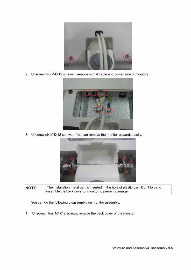
Structure and Assembly/Disassembly 9-5
2. Unscrew two M4X12 screws,remove signal cable and power wire of monitor;
3. Unscrew six M4X12 screws,You can remove the monitor upwards easily.
You can do the following disassembly on monitor assembly.
1. Unscrew four M4X12 screws; remove the back cover of the monitor.
NOTE: The installation metal part is inserted in the hole of plastic part; Don’t force to assemble the back cover of monitor to prevent damage.
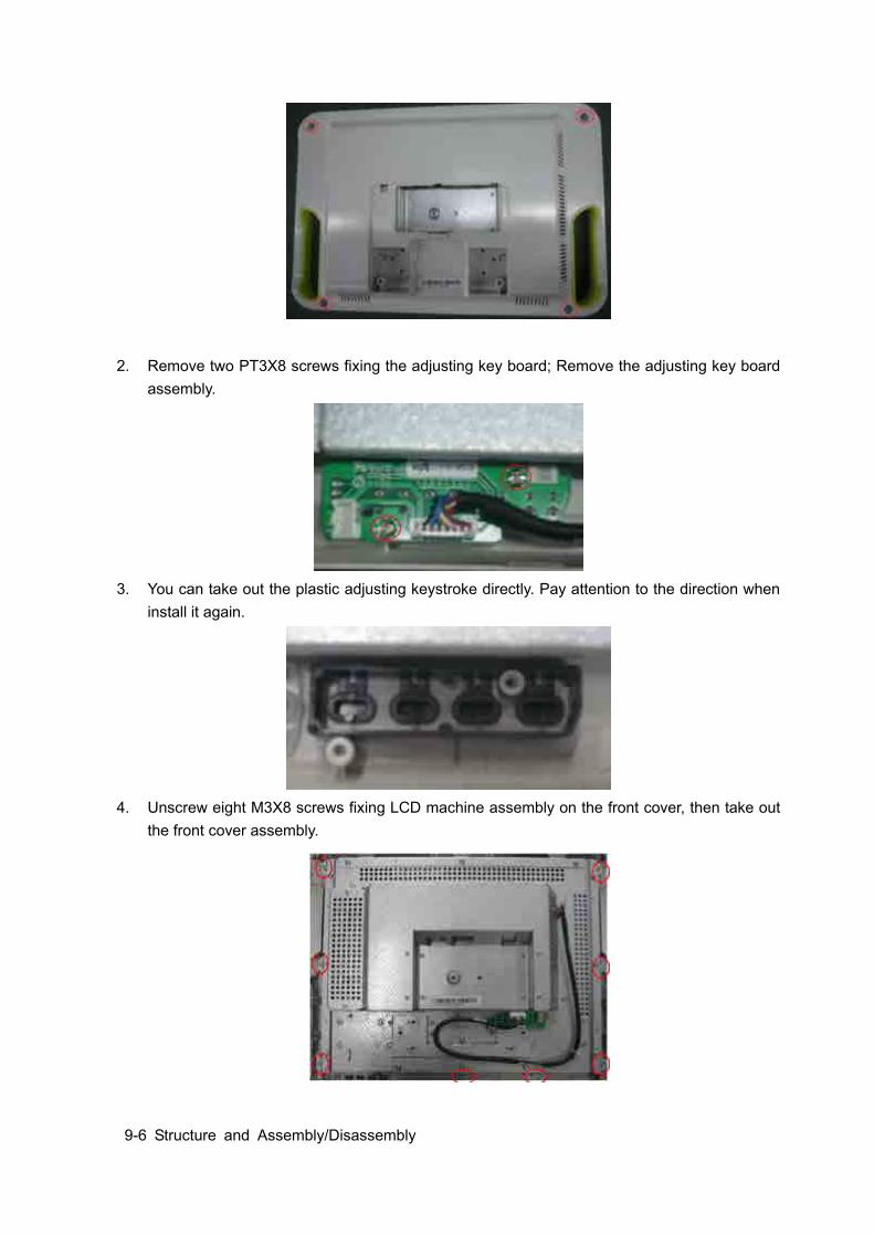
9-6 Structure and Assembly/Disassembly
2. Remove two PT3X8 screws fixing the adjusting key board; Remove the adjusting key board assembly.
3. You can take out the plastic adjusting keystroke directly. Pay attention to the direction when
install it again.
4. Unscrew eight M3X8 screws fixing LCD machine assembly on the front cover, then take out
the front cover assembly.
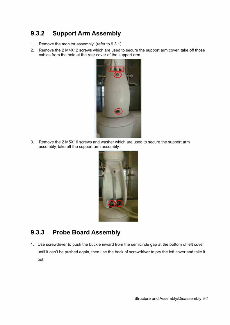
Structure and Assembly/Disassembly 9-7
9.3.2 Support Arm Assembly 1. Remove the monitor assembly. (refer to 9.3.1) 2. Remove the 2 M4X12 screws which are used to secure the support arm cover, take off those
cables from the hole at the rear cover of the support arm.
3. Remove the 2 M5X16 screws and washer which are used to secure the support arm
assembly, take off the support arm assembly.
9.3.3 Probe Board Assembly
1. Use screwdriver to push the buckle inward from the semicircle gap at the bottom of left cover
until it can’t be pushed again, then use the back of screwdriver to pry the left cover and take it
out.
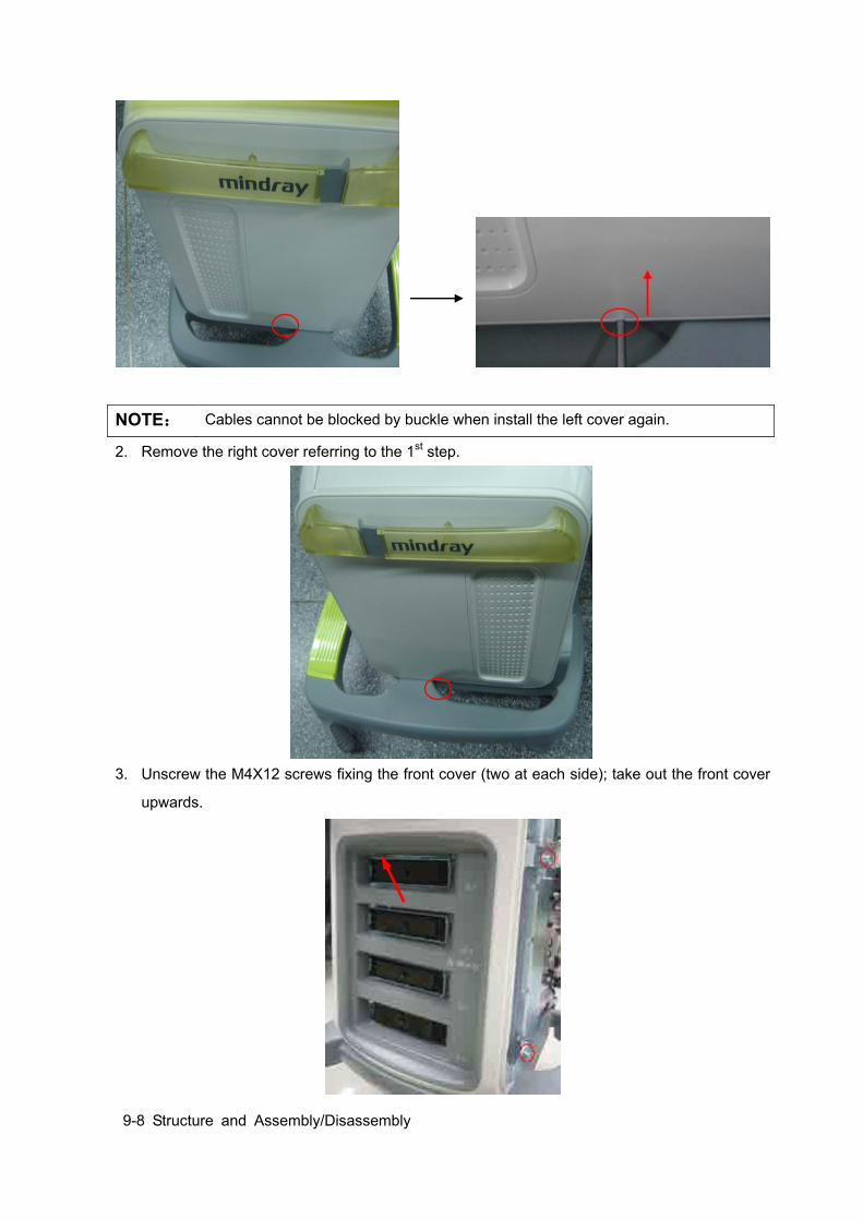
9-8 Structure and Assembly/Disassembly
2. Remove the right cover referring to the 1st step.
3. Unscrew the M4X12 screws fixing the front cover (two at each side); take out the front cover
upwards.
NOTE: Cables cannot be blocked by buckle when install the left cover again.
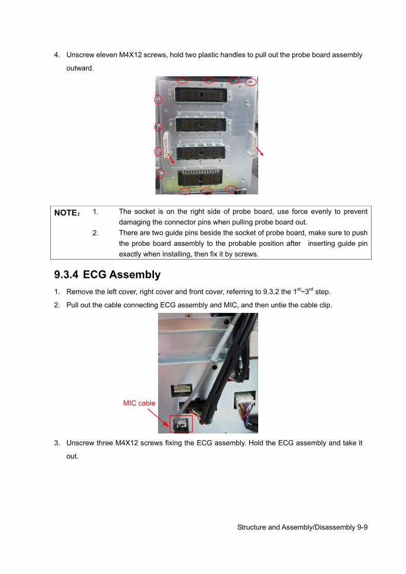
Structure and Assembly/Disassembly 9-9
4. Unscrew eleven M4X12 screws, hold two plastic handles to pull out the probe board assembly
outward.
9.3.4 ECG Assembly 1. Remove the left cover, right cover and front cover, referring to 9.3.2 the 1st~3rd step.
2. Pull out the cable connecting ECG assembly and MIC, and then untie the cable clip.
3. Unscrew three M4X12 screws fixing the ECG assembly. Hold the ECG assembly and take it
out.
NOTE: 1. The socket is on the right side of probe board, use force evenly to prevent damaging the connector pins when pulling probe board out.
2. There are two guide pins beside the socket of probe board, make sure to push
the probe board assembly to the probable position after inserting guide pin exactly when installing, then fix it by screws.
MIC cable
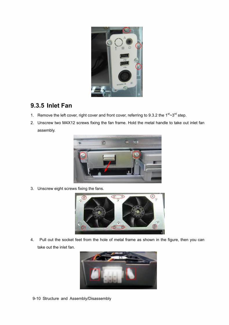
9-10 Structure and Assembly/Disassembly
9.3.5 Inlet Fan 1. Remove the left cover, right cover and front cover, referring to 9.3.2 the 1st~3rd step.
2. Unscrew two M4X12 screws fixing the fan frame. Hold the metal handle to take out inlet fan
assembly.
3. Unscrew eight screws fixing the fans.
4. Pull out the socket feet from the hole of metal frame as shown in the figure, then you can
take out the inlet fan.
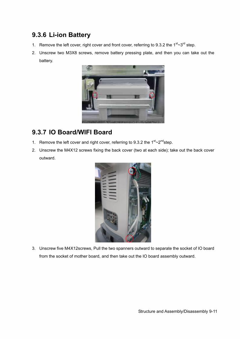
Structure and Assembly/Disassembly 9-11
9.3.6 Li-ion Battery 1. Remove the left cover, right cover and front cover, referring to 9.3.2 the 1st~3rd step.
2. Unscrew two M3X8 screws, remove battery pressing plate, and then you can take out the
battery.
9.3.7 IO Board/WIFI Board 1. Remove the left cover and right cover, referring to 9.3.2 the 1st~2ndstep.
2. Unscrew the M4X12 screws fixing the back cover (two at each side); take out the back cover
outward.
3. Unscrew five M4X12screws, Pull the two spanners outward to separate the socket of IO board
from the socket of mother board, and then take out the IO board assembly outward.
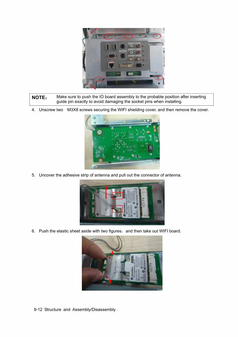
9-12 Structure and Assembly/Disassembly
4. Unscrew two M3X8 screws securing the WIFI shielding cover, and then remove the cover.
5. Uncover the adhesive strip of antenna and pull out the connector of antenna.
6. Push the elastic sheet aside with two figures,and then take out WIFI board.
NOTE: Make sure to push the IO board assembly to the probable position after inserting guide pin exactly to avoid damaging the socket pins when installing.
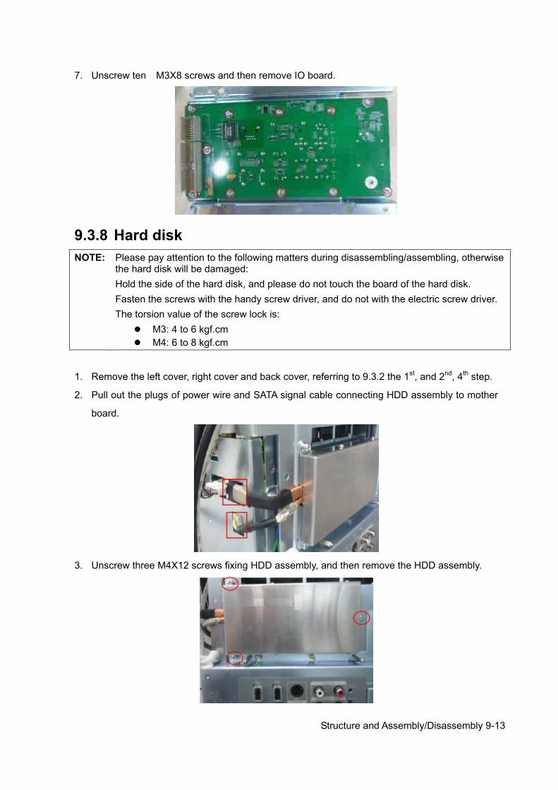
Structure and Assembly/Disassembly 9-13
7. Unscrew ten M3X8 screws and then remove IO board.
9.3.8 Hard disk NOTE: Please pay attention to the following matters during disassembling/assembling, otherwise
the hard disk will be damaged: Hold the side of the hard disk, and please do not touch the board of the hard disk. Fasten the screws with the handy screw driver, and do not with the electric screw driver. The torsion value of the screw lock is:
M3: 4 to 6 kgf.cm M4: 6 to 8 kgf.cm
1. Remove the left cover, right cover and back cover, referring to 9.3.2 the 1st, and 2nd, 4th step.
2. Pull out the plugs of power wire and SATA signal cable connecting HDD assembly to mother
board.
3. Unscrew three M4X12 screws fixing HDD assembly, and then remove the HDD assembly.
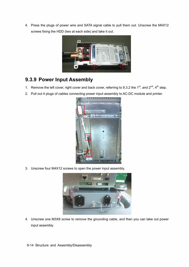
9-14 Structure and Assembly/Disassembly
4. Press the plugs of power wire and SATA signal cable to pull them out. Unscrew the M4X12
screws fixing the HDD (two at each side) and take it out.
9.3.9 Power Input Assembly 1. Remove the left cover, right cover and back cover, referring to 9.3.2 the 1st, and 2nd, 4th step.
2. Pull out 4 plugs of cables connecting power input assembly to AC-DC module and printer.
3. Unscrew four M4X12 screws to open the power input assembly.
4. Unscrew one M3X8 screw to remove the grounding cable, and then you can take out power
input assembly.

Structure and Assembly/Disassembly 9-15
9.3.10 TR board / CW board 1. Remove the left cover, referring to 9.3.2 the 1st step.
2. Unscrew four M4X12 screws fixing the shielding cover of main unit box (two for each), and
then remove the cover.
3. As shown in the figure: there are two plastic detachers on two sides of the board, release
them outwards to a certain position, the TR board and CW board assembly will be released
automatically and then take the assembly out.

9-16 Structure and Assembly/Disassembly
4. Pull out the plug, unscrew two M3X8 screws to remove the CW board, the left is TR board.
9.3.11 Digital Board and CPU Module Assembly Referring to 9.3.9 the 1st~2nd step, and then push the plastic detachers outward with two handles to take out digital board and CPU module assembly.
You can do the following disassembly on digital board and CPU module assembly:
9.3.11.1 CPU Module and 4D&TEE Board 1. Unscrew four M3X30 screws,hold the edge of sheet metal with CPU module to pull out the
module upwards.
NOTE: When installing, Aim at the guiding tracks and use force evenly to insert the assembly to prevent damaging the socket pins, and then push two plastic detachers inward until lock the assembly.
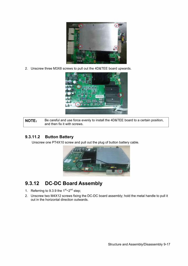
Structure and Assembly/Disassembly 9-17
2. Unscrew three M3X8 screws to pull out the 4D&TEE board upwards.
9.3.11.2 Button Battery Unscrew one PT4X10 screw and pull out the plug of button battery cable.
9.3.12 DC-DC Board Assembly 1. Referring to 9.3.9 the 1st~2nd step; 2. Unscrew two M4X12 screws fixing the DC-DC board assembly; hold the metal handle to pull it
out in the horizontal direction outwards.
NOTE: Be careful and use force evenly to install the 4D&TEE board to a certain position, and then fix it with screws.
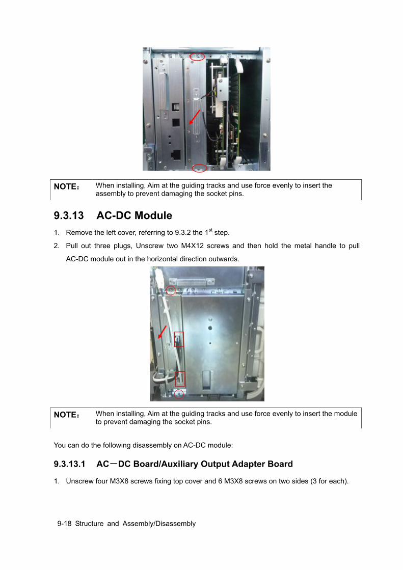
9-18 Structure and Assembly/Disassembly
9.3.13 AC-DC Module 1. Remove the left cover, referring to 9.3.2 the 1st step.
2. Pull out three plugs, Unscrew two M4X12 screws and then hold the metal handle to pull
AC-DC module out in the horizontal direction outwards.
You can do the following disassembly on AC-DC module:
9.3.13.1 AC-DC Board/Auxiliary Output Adapter Board
1. Unscrew four M3X8 screws fixing top cover and 6 M3X8 screws on two sides (3 for each).
NOTE: When installing, Aim at the guiding tracks and use force evenly to insert the assembly to prevent damaging the socket pins.
NOTE: When installing, Aim at the guiding tracks and use force evenly to insert the module to prevent damaging the socket pins.
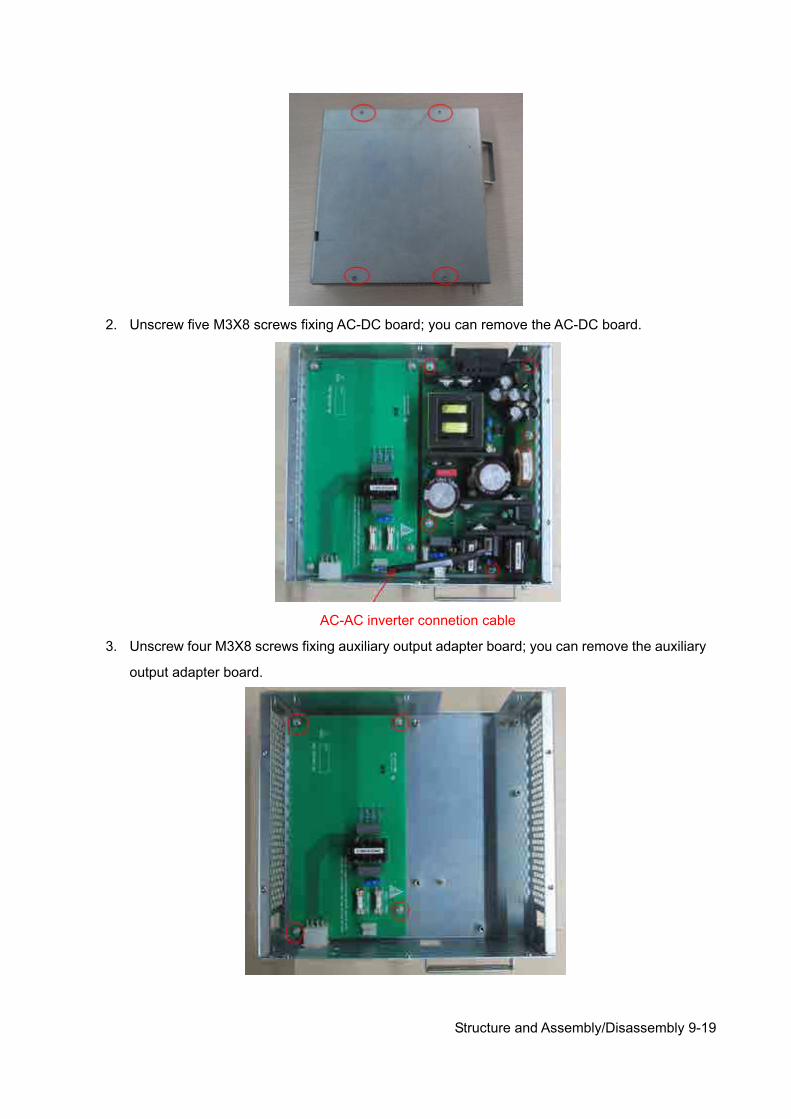
Structure and Assembly/Disassembly 9-19
2. Unscrew five M3X8 screws fixing AC-DC board; you can remove the AC-DC board.
AC-AC inverter connetion cable
3. Unscrew four M3X8 screws fixing auxiliary output adapter board; you can remove the auxiliary
output adapter board.
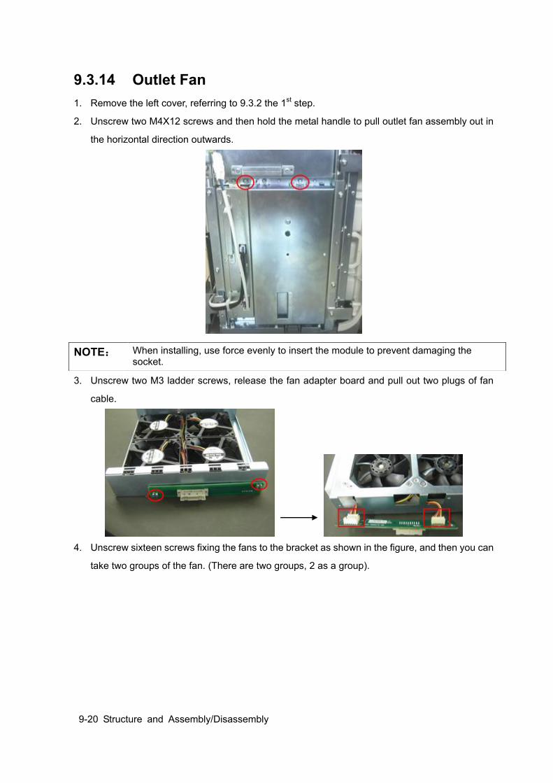
9-20 Structure and Assembly/Disassembly
9.3.14 Outlet Fan 1. Remove the left cover, referring to 9.3.2 the 1st step.
2. Unscrew two M4X12 screws and then hold the metal handle to pull outlet fan assembly out in
the horizontal direction outwards.
3. Unscrew two M3 ladder screws, release the fan adapter board and pull out two plugs of fan
cable.
4. Unscrew sixteen screws fixing the fans to the bracket as shown in the figure, and then you can
take two groups of the fan. (There are two groups, 2 as a group).
NOTE: When installing, use force evenly to insert the module to prevent damaging the socket.

Structure and Assembly/Disassembly 9-21
9.3.15 Motherboard 1. Remove the left cover, right cover, front cover and probe board assembly, referring to 9.3.2.
2. Remove the front cover and IO board assembly, referring to 9.3.6.
3. Remove TR board, digital board and CPU module, AC-DC module and DC-DC board
assembly, referring to 9.3.9~9.3.12.
4. Unscrew one M4X12 grounding screws from the right side of machine.
5. Pull out all the cable plugs; unscrew four M4X12 screws to remove protecting cover of
motherboard.
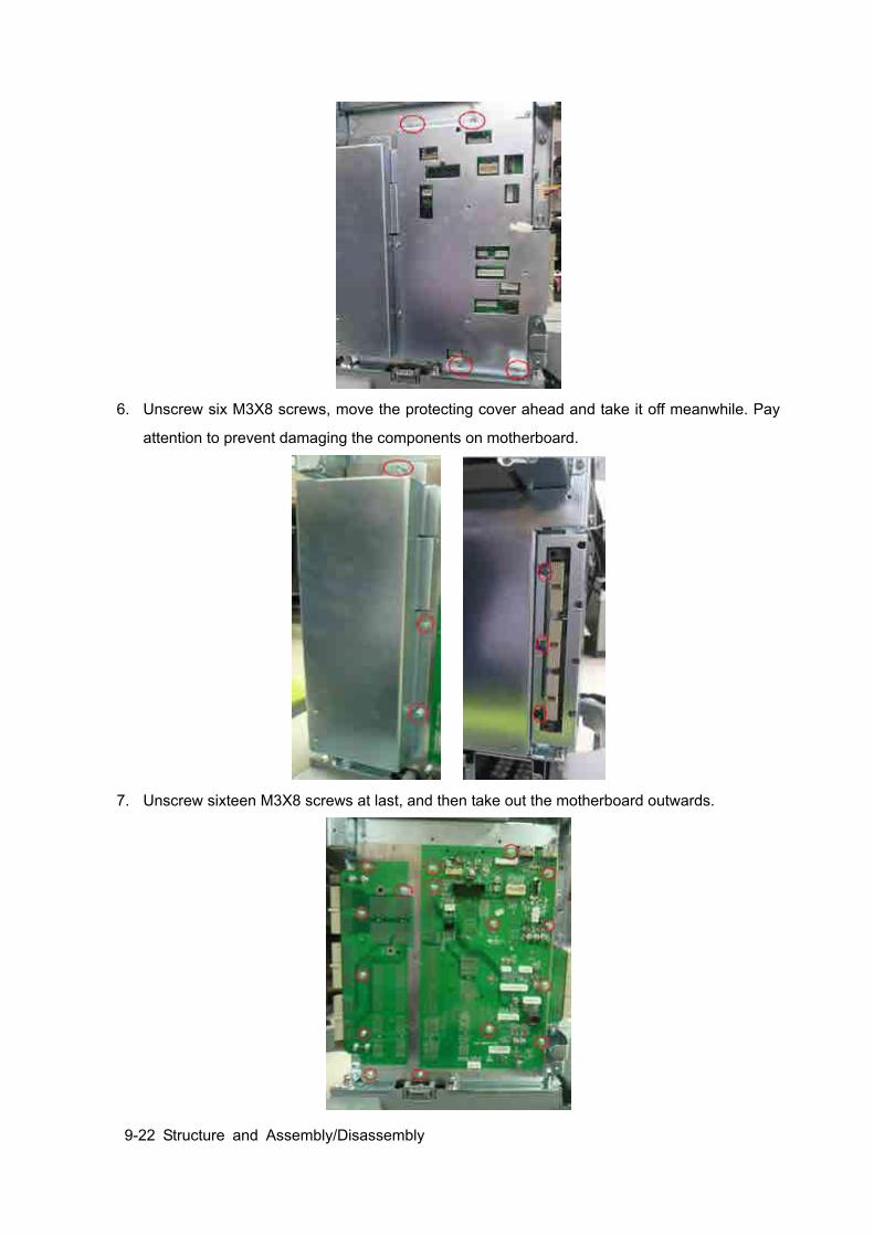
9-22 Structure and Assembly/Disassembly
6. Unscrew six M3X8 screws, move the protecting cover ahead and take it off meanwhile. Pay
attention to prevent damaging the components on motherboard.
7. Unscrew sixteen M3X8 screws at last, and then take out the motherboard outwards.
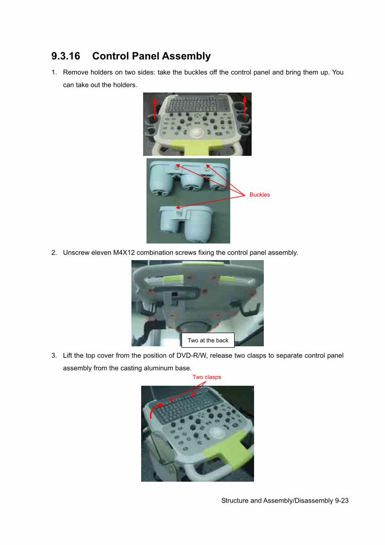
Structure and Assembly/Disassembly 9-23
9.3.16 Control Panel Assembly 1. Remove holders on two sides: take the buckles off the control panel and bring them up. You
can take out the holders.
2. Unscrew eleven M4X12 combination screws fixing the control panel assembly.
3. Lift the top cover from the position of DVD-R/W, release two clasps to separate control panel
assembly from the casting aluminum base.
Buckles
Two at the back
Two clasps
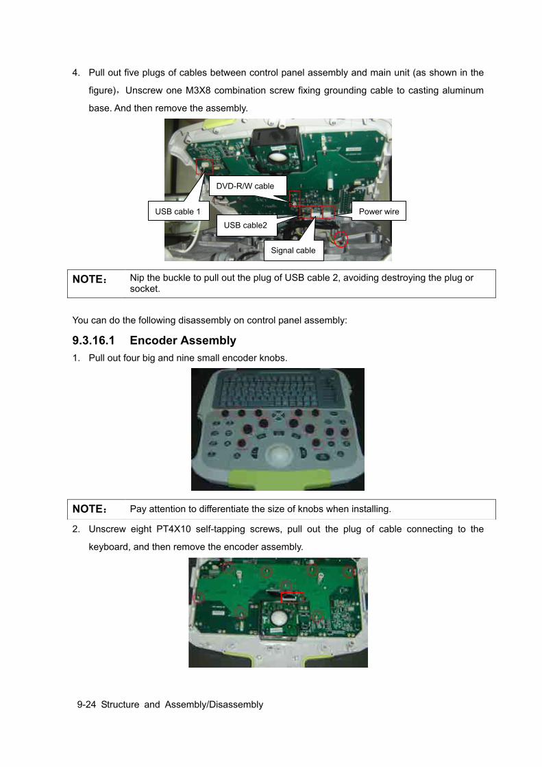
9-24 Structure and Assembly/Disassembly
4. Pull out five plugs of cables between control panel assembly and main unit (as shown in the
figure),Unscrew one M3X8 combination screw fixing grounding cable to casting aluminum
base. And then remove the assembly.
You can do the following disassembly on control panel assembly:
9.3.16.1 Encoder Assembly 1. Pull out four big and nine small encoder knobs.
2. Unscrew eight PT4X10 self-tapping screws, pull out the plug of cable connecting to the
keyboard, and then remove the encoder assembly.
NOTE: Nip the buckle to pull out the plug of USB cable 2, avoiding destroying the plug or socket.
NOTE: Pay attention to differentiate the size of knobs when installing.
Power wire
Signal cable
USB cable 1
DVD-R/W cable
USB cable2
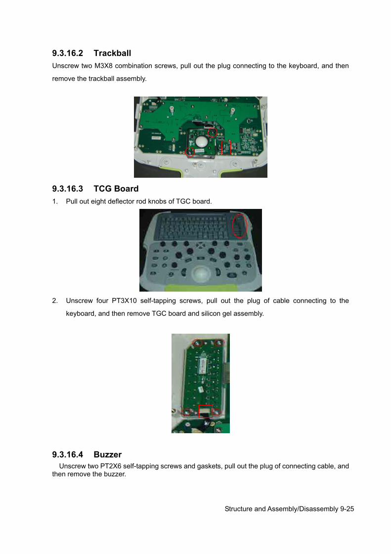
Structure and Assembly/Disassembly 9-25
9.3.16.2 Trackball Unscrew two M3X8 combination screws, pull out the plug connecting to the keyboard, and then
remove the trackball assembly.
9.3.16.3 TCG Board 1. Pull out eight deflector rod knobs of TGC board.
2. Unscrew four PT3X10 self-tapping screws, pull out the plug of cable connecting to the
keyboard, and then remove TGC board and silicon gel assembly.
9.3.16.4 Buzzer Unscrew two PT2X6 self-tapping screws and gaskets, pull out the plug of connecting cable, and then remove the buzzer.
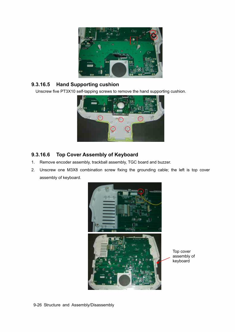
9-26 Structure and Assembly/Disassembly
9.3.16.5 Hand Supporting cushion Unscrew five PT3X10 self-tapping screws to remove the hand supporting cushion.
9.3.16.6 Top Cover Assembly of Keyboard 1. Remove encoder assembly, trackball assembly, TGC board and buzzer.
2. Unscrew one M3X8 combination screw fixing the grounding cable; the left is top cover
assembly of keyboard.
Top cover assembly of keyboard
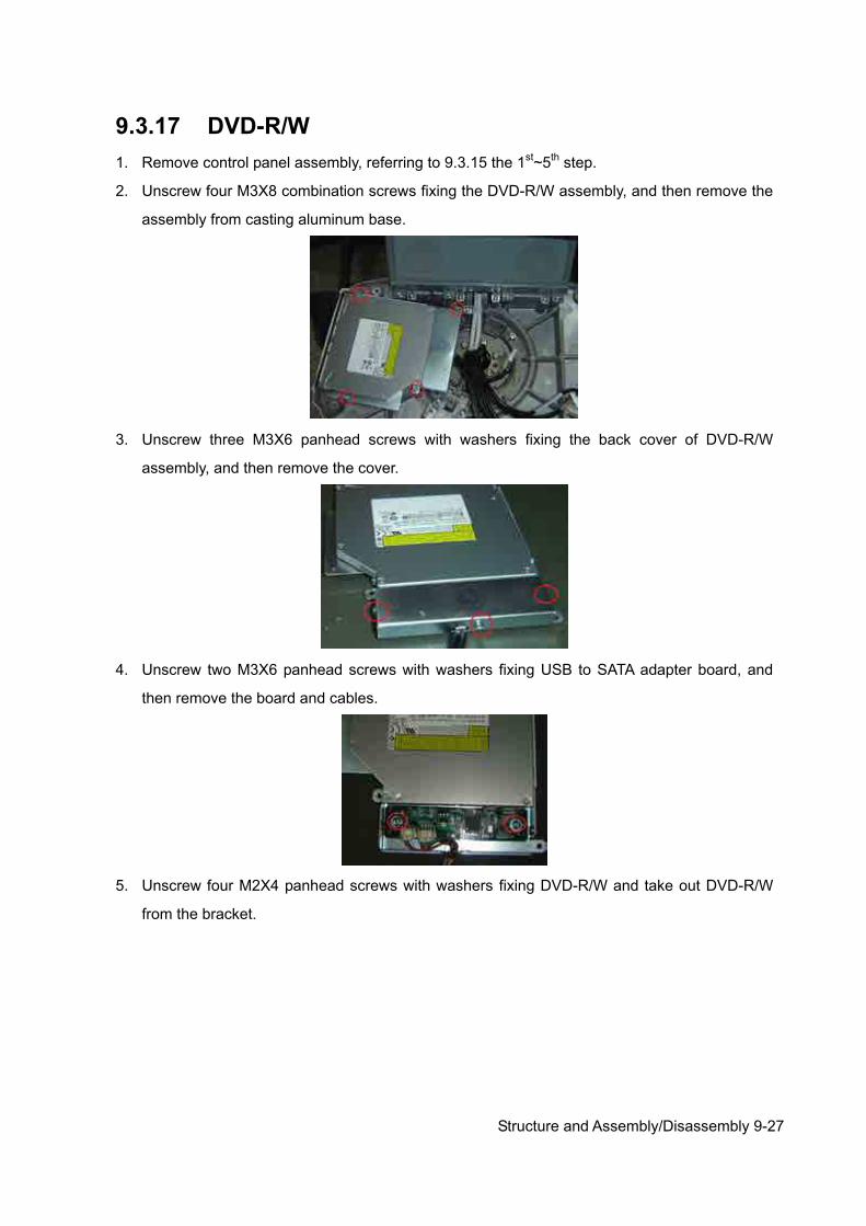
Structure and Assembly/Disassembly 9-27
9.3.17 DVD-R/W 1. Remove control panel assembly, referring to 9.3.15 the 1st~5th step.
2. Unscrew four M3X8 combination screws fixing the DVD-R/W assembly, and then remove the
assembly from casting aluminum base.
3. Unscrew three M3X6 panhead screws with washers fixing the back cover of DVD-R/W
assembly, and then remove the cover.
4. Unscrew two M3X6 panhead screws with washers fixing USB to SATA adapter board, and
then remove the board and cables.
5. Unscrew four M2X4 panhead screws with washers fixing DVD-R/W and take out DVD-R/W
from the bracket.

9-28 Structure and Assembly/Disassembly
9.3.18 Speaker\ Speaker Cover Assembly 1. Remove control panel assembly, referring to 9.3.15 the 1st~5th step.
2. Unscrew four M4X12 combination screws fixing the speaker cover assembly, and then pull the
assembly out from the position as shown by the arrow in the figure below.
3. Unscrew four M3X6 combination screws fixing speaker assembly to the bracket, remove the
bracket and pull out the cables connecting speaker to main unit, you can take out the speaker.
9.3.19 Intra-cavity Probe Bracket and Adapter Part 1. Unscrew two M4X12 combination screws fixing intra-cavity probe holder, and then take out
the holder.
NOTE: Pay attention to the label affixed on the cable to avoid confusing left and right speaker when installing.
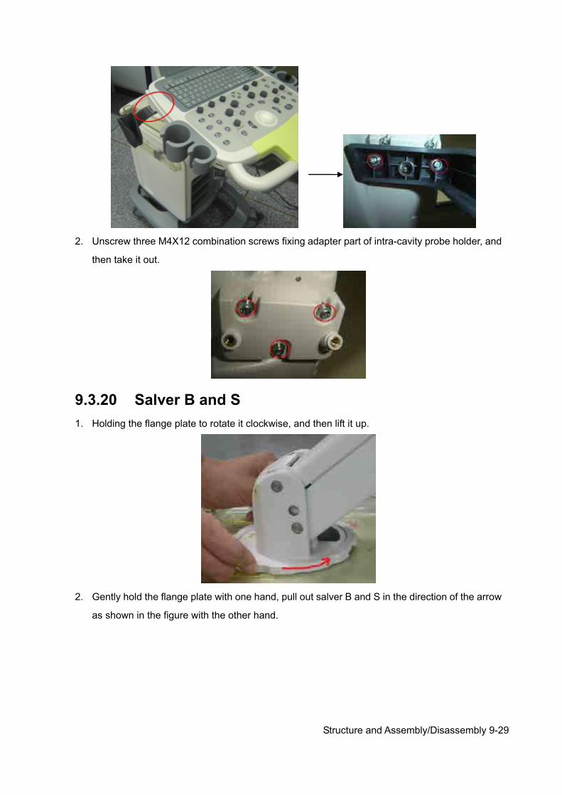
Structure and Assembly/Disassembly 9-29
2. Unscrew three M4X12 combination screws fixing adapter part of intra-cavity probe holder, and
then take it out.
9.3.20 Salver B and S 1. Holding the flange plate to rotate it clockwise, and then lift it up.
2. Gently hold the flange plate with one hand, pull out salver B and S in the direction of the arrow
as shown in the figure with the other hand.
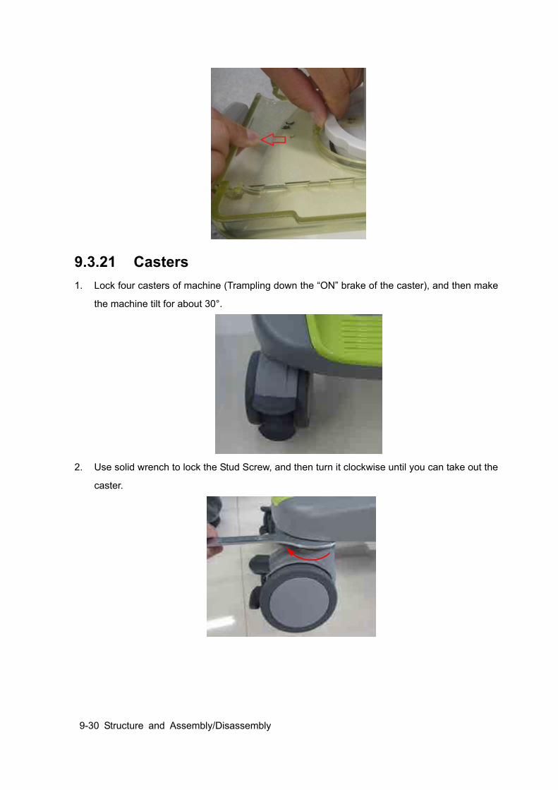
9-30 Structure and Assembly/Disassembly
9.3.21 Casters 1. Lock four casters of machine (Trampling down the “ON” brake of the caster), and then make
the machine tilt for about 30°.
2. Use solid wrench to lock the Stud Screw, and then turn it clockwise until you can take out the
caster.
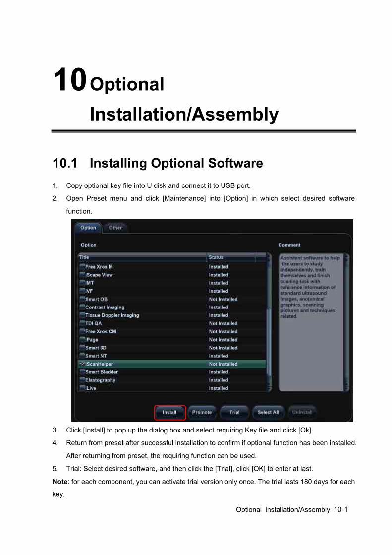
Optional Installation/Assembly 10-1
10 Optional Installation/Assembly
10.1 Installing Optional Software 1. Copy optional key file into U disk and connect it to USB port.
2. Open Preset menu and click [Maintenance] into [Option] in which select desired software
function.
3. Click [Install] to pop up the dialog box and select requiring Key file and click [Ok].
4. Return from preset after successful installation to confirm if optional function has been installed.
After returning from preset, the requiring function can be used.
5. Trial: Select desired software, and then click the [Trial], click [OK] to enter at last.
Note: for each component, you can activate trial version only once. The trial lasts 180 days for each
key.
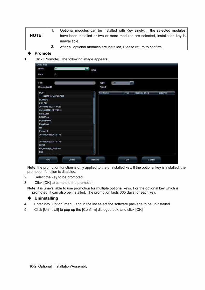
10-2 Optional Installation/Assembly
Promote 1. Click [Promote]. The following image appears:
Note: the promotion function is only applied to the uninstalled key. If the optional key is installed, the promotion function is disabled.
2. Select the key to be promoted. 3. Click [OK] to complete the promotion.
Note: it is unavailable to use promotion for multiple optional keys. For the optional key which is promoted, it can also be installed. The promotion lasts 365 days for each key.
Uninstalling 4. Enter into [Option] menu, and in the list select the software package to be uninstalled. 5. Click [Uninstall] to pop up the [Confirm] dialogue box, and click [OK];
NOTE: 1. Optional modules can be installed with Key singly. If the selected modules
have been installed or two or more modules are selected, installation key is unavailable.
2. After all optional modules are installed, Please return to confirm.
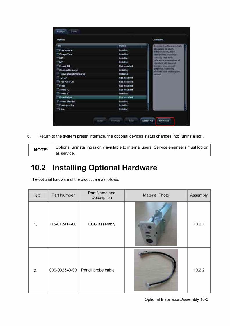
Optional Installation/Assembly 10-3
6. Return to the system preset interface, the optional devices status changes into "uninstalled".
10.2 Installing Optional Hardware The optional hardware of the product are as follows:
NO. Part Number Part Name and Description Material Photo Assembly
1. 115-012414-00 ECG assembly
10.2.1
2. 009-002540-00 Pencil probe cable
10.2.2
NOTE: Optional uninstalling is only available to internal users. Service engineers must log on as service.
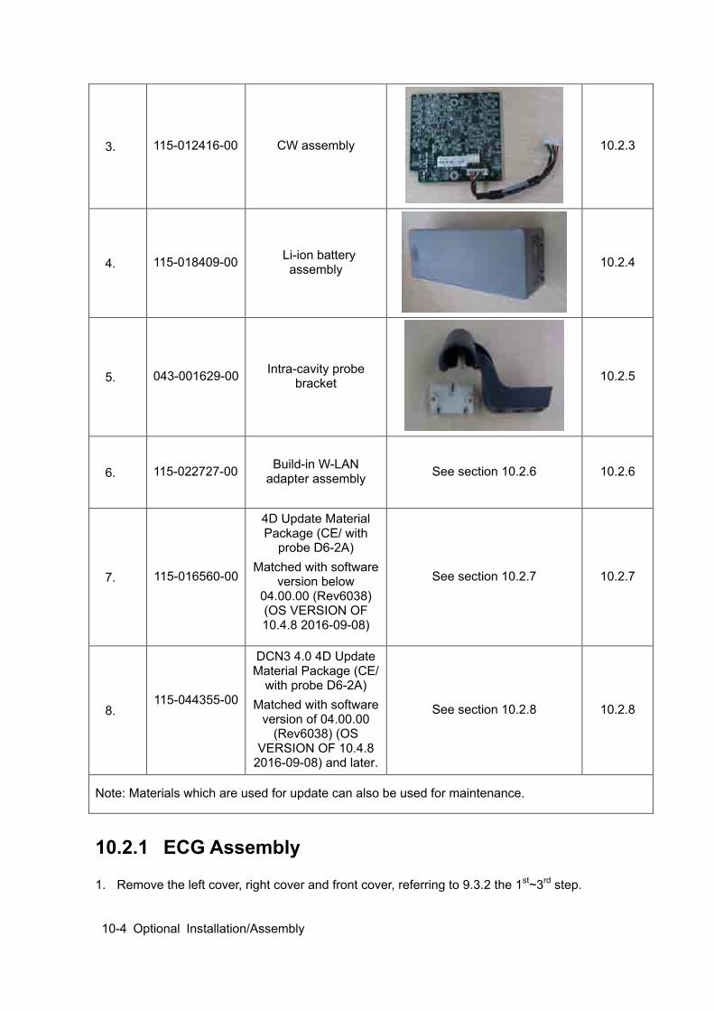
10-4 Optional Installation/Assembly
3. 115-012416-00 CW assembly
10.2.3
4. 115-018409-00 Li-ion battery assembly
10.2.4
5. 043-001629-00 Intra-cavity probe bracket
10.2.5
6. 115-022727-00 Build-in W-LAN adapter assembly See section 10.2.6 10.2.6
7. 115-016560-00
4D Update Material Package (CE/ with
probe D6-2A) Matched with software
version below 04.00.00 (Rev6038) (OS VERSION OF 10.4.8 2016-09-08)
See section 10.2.7 10.2.7
8. 115-044355-00
DCN3 4.0 4D Update Material Package (CE/
with probe D6-2A) Matched with software
version of 04.00.00 (Rev6038) (OS
VERSION OF 10.4.8 2016-09-08) and later.
See section 10.2.8 10.2.8
Note: Materials which are used for update can also be used for maintenance.
10.2.1 ECG Assembly
1. Remove the left cover, right cover and front cover, referring to 9.3.2 the 1st~3rd step.
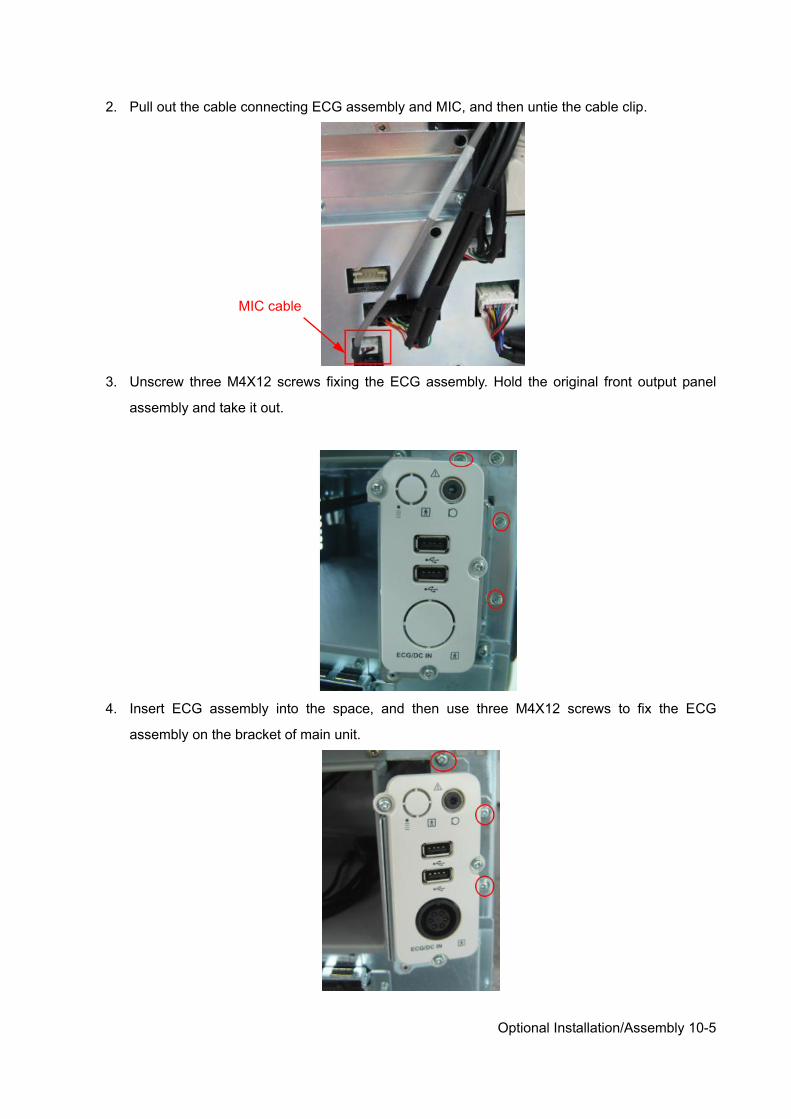
Optional Installation/Assembly 10-5
2. Pull out the cable connecting ECG assembly and MIC, and then untie the cable clip.
3. Unscrew three M4X12 screws fixing the ECG assembly. Hold the original front output panel
assembly and take it out.
4. Insert ECG assembly into the space, and then use three M4X12 screws to fix the ECG
assembly on the bracket of main unit.
MIC cable

10-6 Optional Installation/Assembly
5. Insert the connector of MIC cable into the corresponding socket on motherboard (as shown in
the figure).
6. Install the front cover, left cover and right cover at last, the installation is finished.
10.2.2 Pencil Probe Cable
NOTE: 1. The CW assembly should be configured before installing the pencil probe.
2. This probe is not available in FDA region.
1. Remove the left cover, right cover and front cover, refer to step 1 to 3 in section 9.3.2. 2. Remove the ECG assembly (or front output panel), refer to step 2 and 3 in section 9.3.3. 3. Remove the knockout cover for the pencil probe port on the panel. (Take the panel with ECG
assembly as an example, installing procedures are the same for the front output panel).
4. See figure below. Scroll the hexagon nut to the end (next to the conductive fabric, on the top of
the red mark), pass through the metal plate, and lock the nut on the metal plate.
MIC cable
Knockout cover
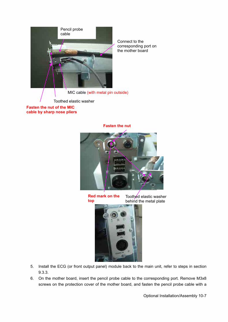
Optional Installation/Assembly 10-7
5. Install the ECG (or front output panel) module back to the main unit, refer to steps in section
9.3.3. 6. On the mother board, insert the pencil probe cable to the corresponding port. Remove M3x8
screws on the protection cover of the mother board, and fasten the pencil probe cable with a
Connect to the corresponding port on the mother board
Pencil probe cable
Toothed elastic washer
MIC cable (with metal pin outside)
Fasten the nut of the MIC cable by sharp nose pliers
Fasten the nut
Red mark on the top
Toothed elastic washer behind the metal plate
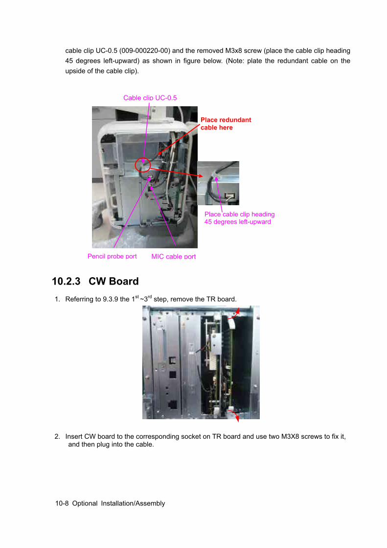
10-8 Optional Installation/Assembly
cable clip UC-0.5 (009-000220-00) and the removed M3x8 screw (place the cable clip heading 45 degrees left-upward) as shown in figure below. (Note: plate the redundant cable on the upside of the cable clip).
10.2.3 CW Board 1. Referring to 9.3.9 the 1st ~3rd step, remove the TR board.
2. Insert CW board to the corresponding socket on TR board and use two M3X8 screws to fix it, and then plug into the cable.
Place cable clip heading 45 degrees left-upward
Pencil probe port MIC cable port
Cable clip UC-0.5
Place redundant cable here
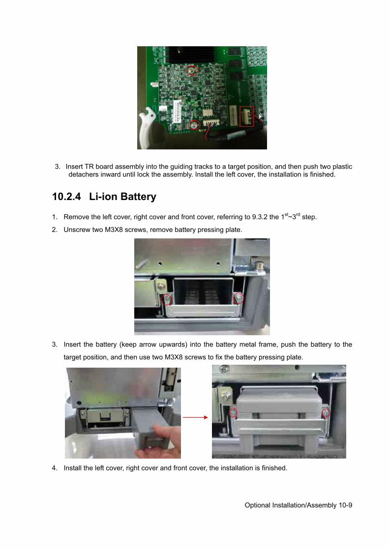
Optional Installation/Assembly 10-9
3. Insert TR board assembly into the guiding tracks to a target position, and then push two plastic detachers inward until lock the assembly. Install the left cover, the installation is finished.
10.2.4 Li-ion Battery
1. Remove the left cover, right cover and front cover, referring to 9.3.2 the 1st~3rd step.
2. Unscrew two M3X8 screws, remove battery pressing plate.
3. Insert the battery (keep arrow upwards) into the battery metal frame, push the battery to the
target position, and then use two M3X8 screws to fix the battery pressing plate.
4. Install the left cover, right cover and front cover, the installation is finished.
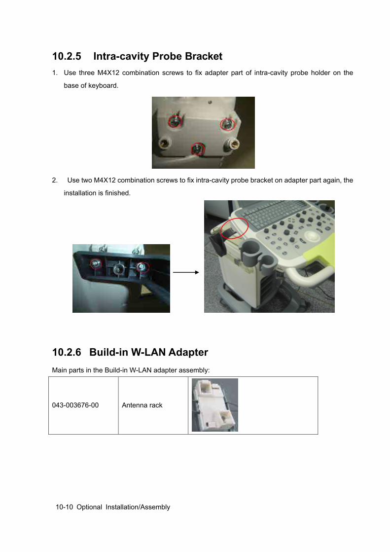
10-10 Optional Installation/Assembly
10.2.5 Intra-cavity Probe Bracket 1. Use three M4X12 combination screws to fix adapter part of intra-cavity probe holder on the
base of keyboard.
2. Use two M4X12 combination screws to fix intra-cavity probe bracket on adapter part again, the
installation is finished.
10.2.6 Build-in W-LAN Adapter Main parts in the Build-in W-LAN adapter assembly:
043-003676-00 Antenna rack
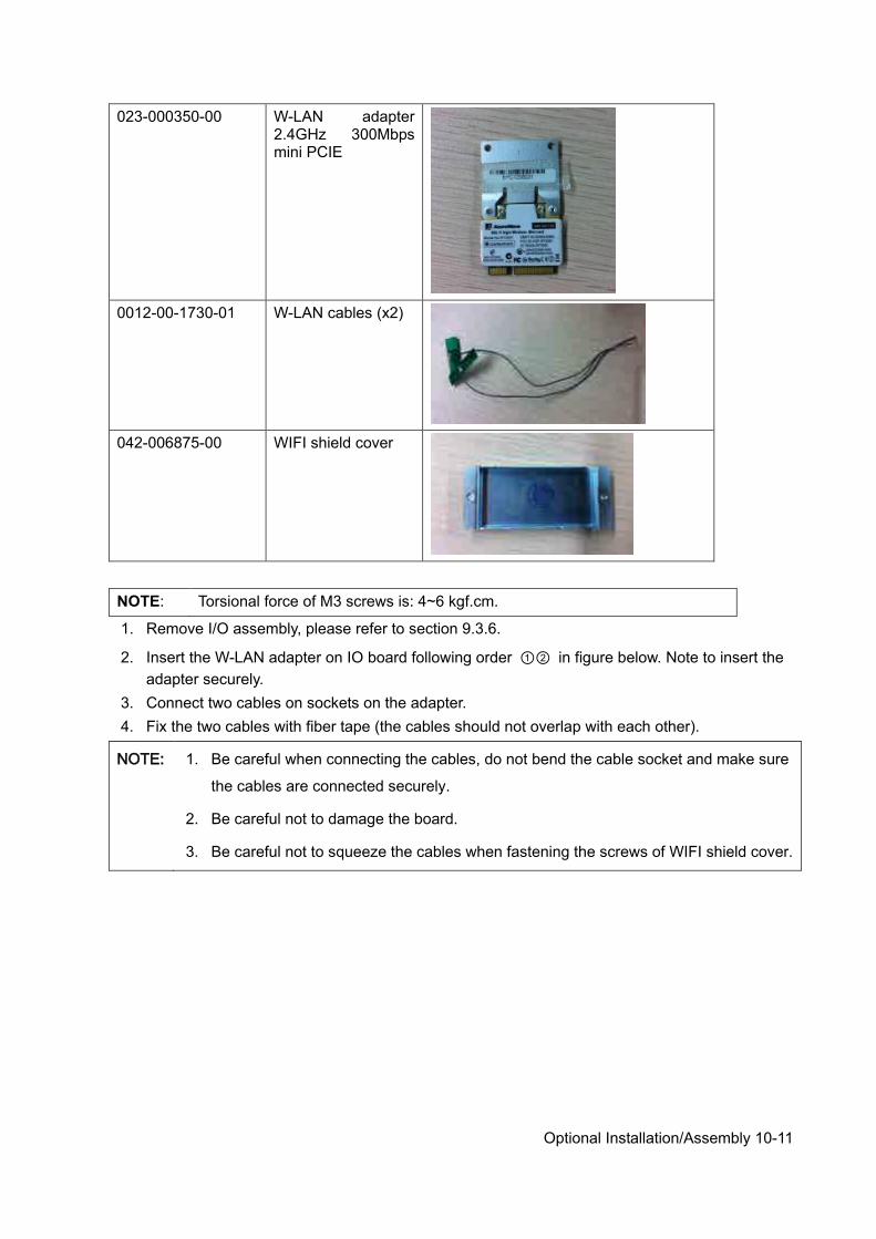
Optional Installation/Assembly 10-11
023-000350-00 W-LAN adapter 2.4GHz 300Mbps mini PCIE
0012-00-1730-01 W-LAN cables (x2)
042-006875-00 WIFI shield cover
NOTE: Torsional force of M3 screws is: 4~6 kgf.cm.
1. Remove I/O assembly, please refer to section 9.3.6.
2. Insert the W-LAN adapter on IO board following order ①② in figure below. Note to insert the adapter securely.
3. Connect two cables on sockets on the adapter. 4. Fix the two cables with fiber tape (the cables should not overlap with each other).
NOTE: 1. Be careful when connecting the cables, do not bend the cable socket and make sure
the cables are connected securely.
2. Be careful not to damage the board.
3. Be careful not to squeeze the cables when fastening the screws of WIFI shield cover.
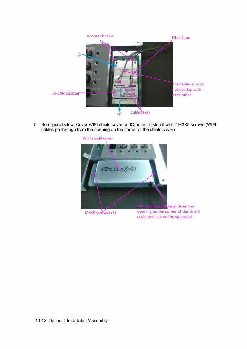
10-12 Optional Installation/Assembly
5. See figure below. Cover WIFI shield cover on IO board, fasten it with 2 M3X8 screws (WIFI
cables go through from the opening on the corner of the shield cover).
W-LAN adapter
Cables (x2) ①
②
The cables should not overlap with each other
Adapter buckle Fiber tape
WIFI shield cover
M3X8 screws (x2) WIFI cables go through from the opening on the corner of the shield cover and can not be squeezed
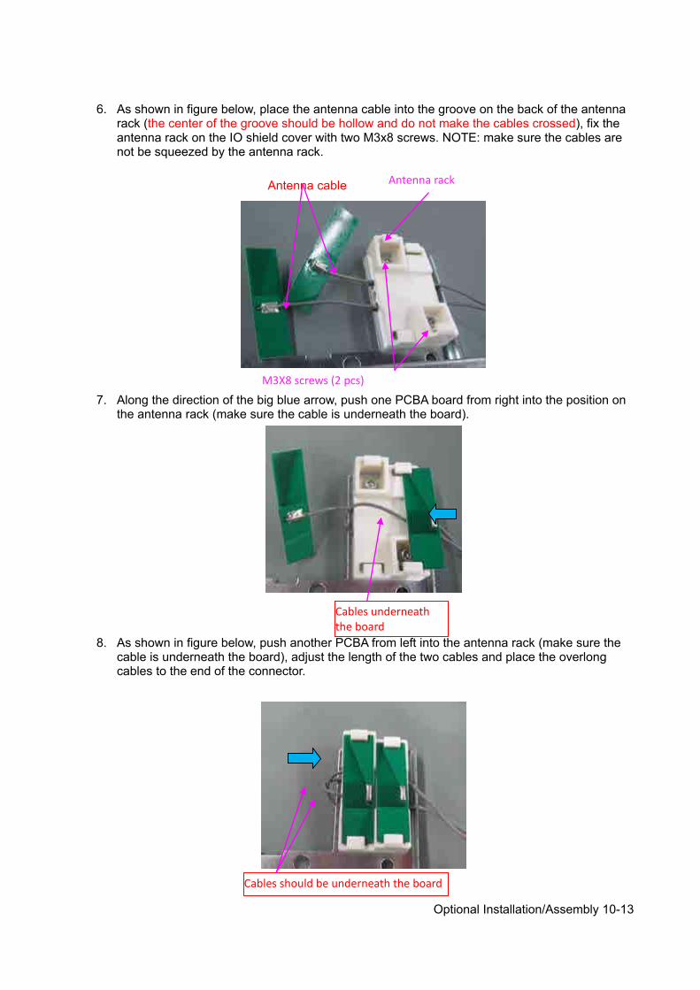
Optional Installation/Assembly 10-13
6. As shown in figure below, place the antenna cable into the groove on the back of the antenna
rack (the center of the groove should be hollow and do not make the cables crossed), fix the antenna rack on the IO shield cover with two M3x8 screws. NOTE: make sure the cables are not be squeezed by the antenna rack.
7. Along the direction of the big blue arrow, push one PCBA board from right into the position on the antenna rack (make sure the cable is underneath the board).
8. As shown in figure below, push another PCBA from left into the antenna rack (make sure the
cable is underneath the board), adjust the length of the two cables and place the overlong cables to the end of the connector.
Antenna rack Antenna cable
M3X8 screws (2 pcs)
Cables underneath the board
Cables should be underneath the board
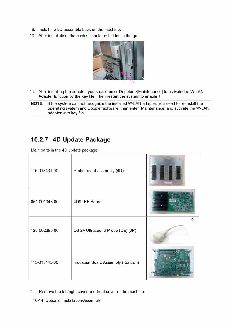
10-14 Optional Installation/Assembly
9. Install the I/O assemble back on the machine. 10. After installation, the cables should be hidden in the gap.
11. After installing the adapter, you should enter Doppler->[Maintenance] to activate the W-LAN Adapter function by the key file. Then restart the system to enable it.
NOTE: If the system can not recognize the installed W-LAN adapter, you need to re-install the operating system and Doppler software, then enter [Maintenance] and activate the W-LAN adapter with key file.
10.2.7 4D Update Package Main parts in the 4D update package.
115-013431-00 Probe board assembly (4D)
051-001048-00 4D&TEE Board
120-002380-00 D6-2A Ultrasound Probe (CE) (JP)
115-013445-00 Industrial Board Assembly (Kontron)
1. Remove the left/right cover and front cover of the machine.
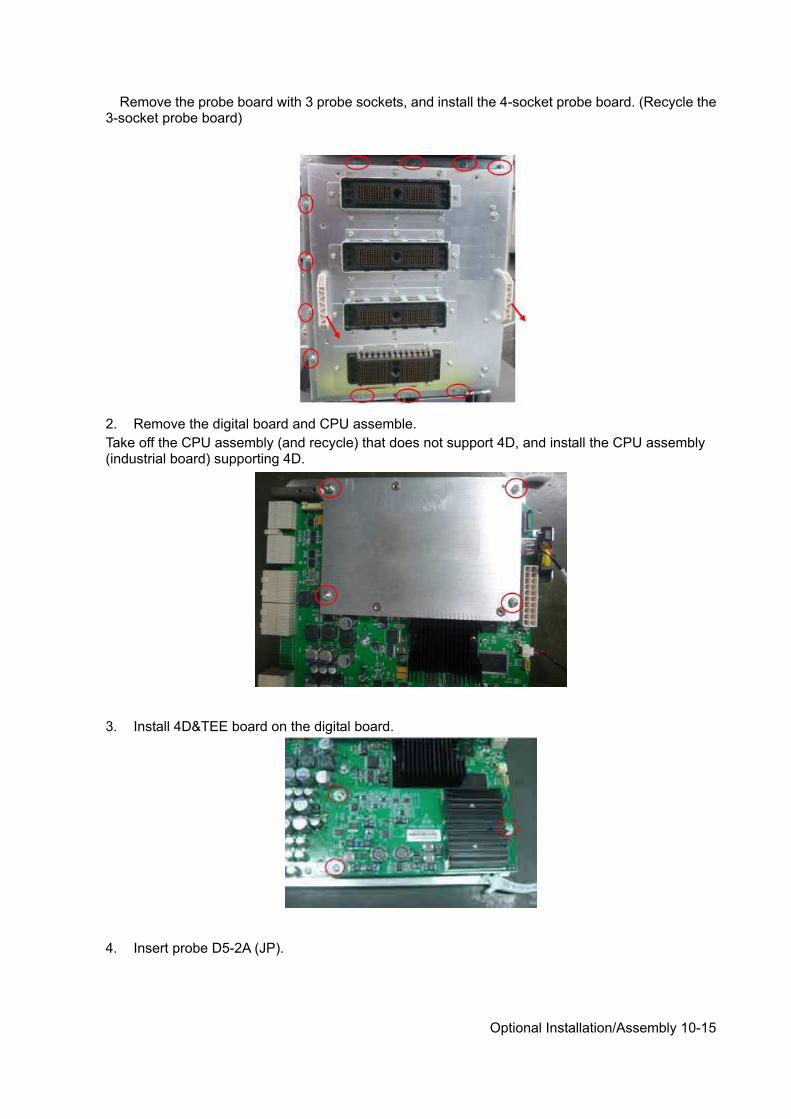
Optional Installation/Assembly 10-15
Remove the probe board with 3 probe sockets, and install the 4-socket probe board. (Recycle the 3-socket probe board)
2. Remove the digital board and CPU assemble. Take off the CPU assembly (and recycle) that does not support 4D, and install the CPU assembly (industrial board) supporting 4D.
3. Install 4D&TEE board on the digital board.
4. Insert probe D5-2A (JP).

10-16 Optional Installation/Assembly
10.2.8 DCN3 4.0 4D Update Package (Suitable for N3 4.0
Version) Matched with software version of 04.00.00 (Rev6038) (OS VERSION OF 10.4.8 2016-09-08) and later. Main parts in the 4D update package.
115-013431-00 Probe board assembly (4D)
051-001048-00 4D&TEE Board
120-002380-00 D6-2A Ultrasound Probe (CE) (JP)
1. Remove the left/right cover and front cover of the machine. Remove the probe board with 3 probe sockets, and install the 4-socket probe board. (Recycle the 3-socket probe board)
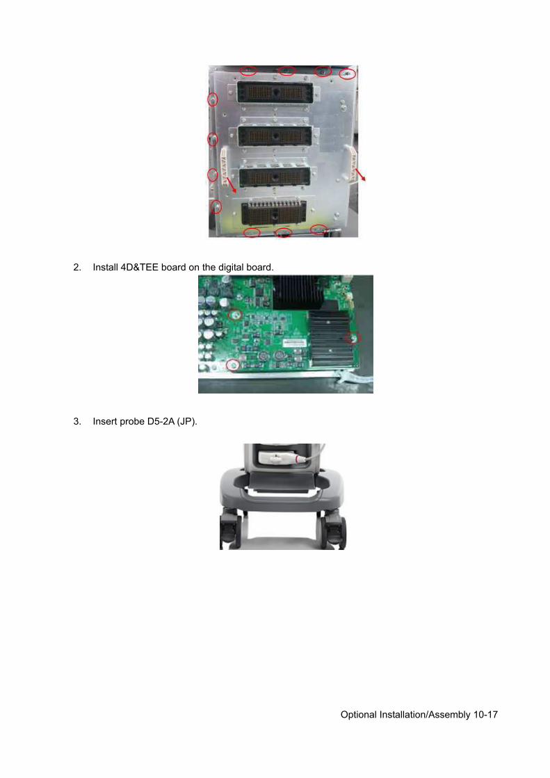
Optional Installation/Assembly 10-17
2. Install 4D&TEE board on the digital board.
3. Insert probe D5-2A (JP).

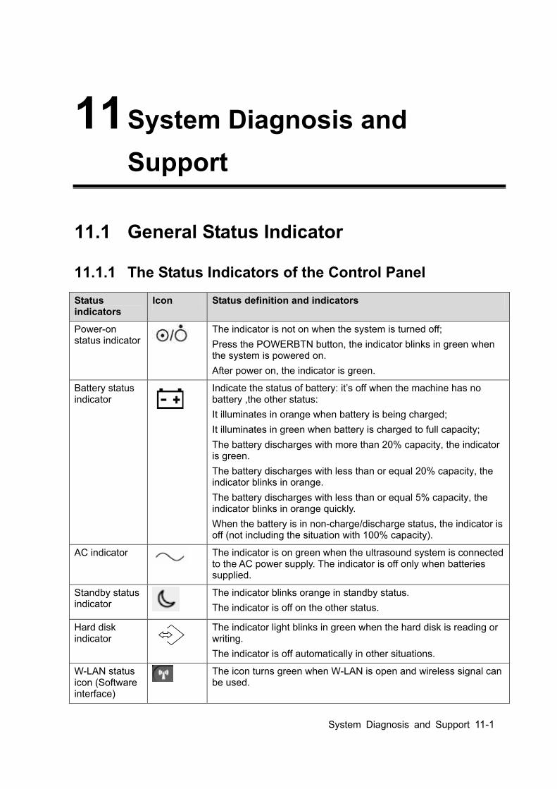
System Diagnosis and Support 11-1
11 System Diagnosis and Support
11.1 General Status Indicator
11.1.1 The Status Indicators of the Control Panel
Status indicators
Icon Status definition and indicators
Power-on status indicator
The indicator is not on when the system is turned off; Press the POWERBTN button, the indicator blinks in green when the system is powered on. After power on, the indicator is green.
Battery status indicator
Indicate the status of battery: it’s off when the machine has no battery ,the other status: It illuminates in orange when battery is being charged; It illuminates in green when battery is charged to full capacity; The battery discharges with more than 20% capacity, the indicator is green. The battery discharges with less than or equal 20% capacity, the indicator blinks in orange. The battery discharges with less than or equal 5% capacity, the indicator blinks in orange quickly. When the battery is in non-charge/discharge status, the indicator is off (not including the situation with 100% capacity).
AC indicator
The indicator is on green when the ultrasound system is connected to the AC power supply. The indicator is off only when batteries supplied.
Standby status indicator
The indicator blinks orange in standby status. The indicator is off on the other status.
Hard disk indicator
The indicator light blinks in green when the hard disk is reading or writing. The indicator is off automatically in other situations.
W-LAN status icon (Software interface)
The icon turns green when W-LAN is open and wireless signal can be used.
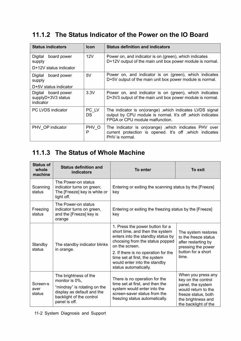
11-2 System Diagnosis and Support
11.1.2 The Status Indicator of the Power on the IO Board
Status indicators Icon Status definition and indicators
Digital board power supply D+12V status indicator
12V Power on, and indicator is on (green), which indicates D+12V output of the main unit box power module is normal.
Digital board power supply D+5V status indicator
5V Power on, and indicator is on (green), which indicates D+5V output of the main unit box power module is normal.
Digital board power supplyD+3V3 status indicator
3.3V Power on, and indicator is on (green), which indicates D+3V3 output of the main unit box power module is normal.
PC LVDS indicator PC_LVDS
The indicator is on(orange) ,which indicates LVDS signal output by CPU module is normal. It’s off ,which indicates FPGA or CPU module malfunction.
PHV_OP indicator PHV_OP
The indicator is on(orange) ,which indicates PHV over current protection is opened. It’s off ,which indicates PHV is normal.
11.1.3 The Status of Whole Machine
Status of whole
machine
Status definition and indicators To enter To exit
Scanning status
The Power-on status indicator turns on green; The [Freeze] key is white or light off.
Entering or exiting the scanning status by the [Freeze] key
Freezing status
The Power-on status indicator turns on green, and the [Freeze] key is orange
Entering or exiting the freezing status by the [Freeze] key
Standby status
The standby indicator blinks in orange.
1. Press the power button for a short time, and then the system enters into the standby status by choosing from the status popped on the screen. 2. If there is no operation for the time set at first, the system would enter into the standby status automatically.
The system restores to the freeze status after restarting by pressing the power button for a short time.
Screen-saver status
The brightness of the monitor is 0%, “mindray” is rotating on the display as default and the backlight of the control panel is off.
There is no operation for the time set at first, and then the system would enter into the screen-saver status from the freezing status automatically.
When you press any key on the control panel, the system would return to the freeze status, both the brightness and the backlight of the
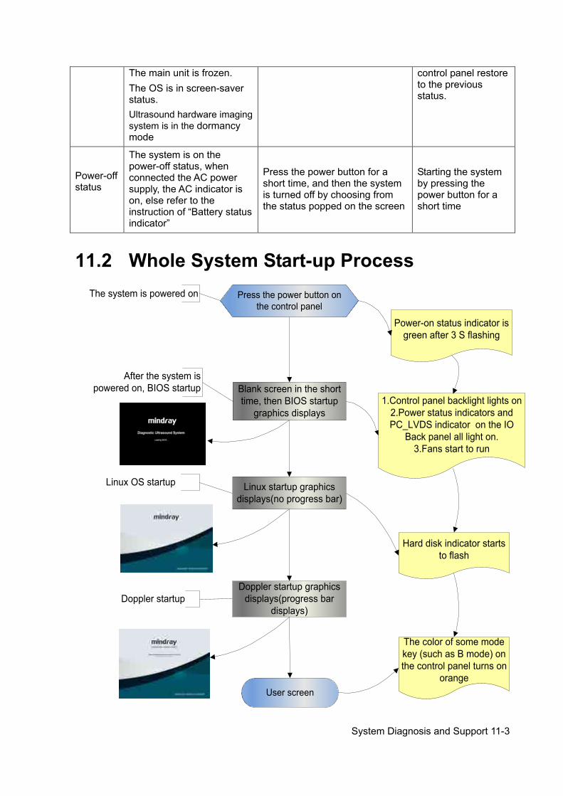
System Diagnosis and Support 11-3
The main unit is frozen. The OS is in screen-saver status. Ultrasound hardware imaging system is in the dormancy mode
control panel restore to the previous status.
Power-off status
The system is on the power-off status, when connected the AC power supply, the AC indicator is on, else refer to the instruction of “Battery status indicator”
Press the power button for a short time, and then the system is turned off by choosing from the status popped on the screen
Starting the system by pressing the power button for a short time
11.2 Whole System Start-up Process The system is powered on
User screen
Press the power button on the control panel
Blank screen in the short time, then BIOS startup
graphics displays
Linux startup graphics displays(no progress bar)
Doppler startup graphics displays(progress bar
displays)
Linux OS startup
Doppler startup
After the system is powered on, BIOS startup
Power-on status indicator is green after 3 S flashing
Hard disk indicator starts to flash
The color of some mode key (such as B mode) on the control panel turns on
orange
1.Control panel backlight lights on2.Power status indicators and PC_LVDS indicator on the IO
Back panel all light on.3.Fans start to run
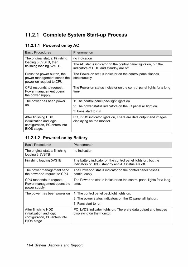
11-4 System Diagnosis and Support
11.2.1 Complete System Start-up Process
11.2.1.1 Powered on by AC Basic Procedures Phenomenon
The original status: Finishing loading 3.3VSTB, then finishing loading 5VSTB.
no indication
The AC status indicator on the control panel lights on, but the indicators of HDD and standby are off.
Press the power button, the power management sends the power-on request to CPU.
The Power-on status indicator on the control panel flashes continuously.
CPU responds to request. Power management opens the power supply.
The Power-on status indicator on the control panel lights for a long time.
The power has been power on.
1: The control panel backlight lights on. 2: The power status indicators on the IO panel all light on. 3: Fans start to run.
After finishing HDD initialization and logic configuration, PC enters into BIOS stage.
PC_LVDS indicator lights on, There are data output and images displaying on the monitor.
11.2.1.2 Powered on by Battery Basic Procedures Phenomenon
The original status: finishing loading 3.3VSTB
no indication
Finishing loading 5VSTB The battery indicator on the control panel lights on, but the indicators of HDD, standby and AC status are off.
The power management send the power-on request to CPU
The Power-on status indicator on the control panel flashes continuously.
CPU responds to request, Power management opens the power supply.
The Power-on status indicator on the control panel lights for a long time.
The power has been power on 1: The control panel backlight lights on. 2: The power status indicators on the IO panel all light on. 3: Fans start to run.
After finishing HDD initialization and logic configuration, PC enters into BIOS stage
PC_LVDS indicator lights on, There are data output and images displaying on the monitor.
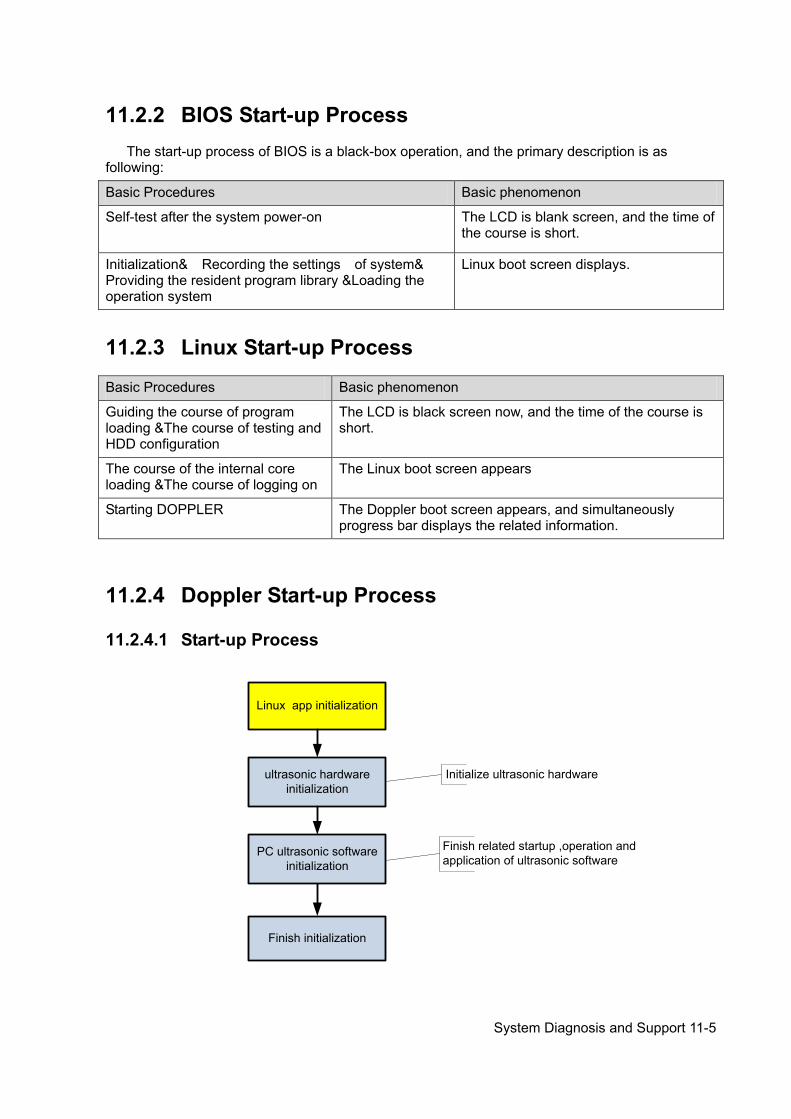
System Diagnosis and Support 11-5
11.2.2 BIOS Start-up Process The start-up process of BIOS is a black-box operation, and the primary description is as
following:
Basic Procedures Basic phenomenon
Self-test after the system power-on The LCD is blank screen, and the time of the course is short.
Initialization& Recording the settings of system& Providing the resident program library &Loading the operation system
Linux boot screen displays.
11.2.3 Linux Start-up Process
Basic Procedures Basic phenomenon
Guiding the course of program loading &The course of testing and HDD configuration
The LCD is black screen now, and the time of the course is short.
The course of the internal core loading &The course of logging on
The Linux boot screen appears
Starting DOPPLER The Doppler boot screen appears, and simultaneously progress bar displays the related information.
11.2.4 Doppler Start-up Process
11.2.4.1 Start-up Process
Linux app initialization
ultrasonic hardware initialization
Finish initialization
Finish related startup ,operation and application of ultrasonic software
Initialize ultrasonic hardware
PC ultrasonic software initialization

11-6 System Diagnosis and Support
11.2.4.2 Details Now, DOPPLER starting is in increments of 20dB, and the detailed course is as following:
Basic Procedures Sub-procedures Basic phenomenon Description
Linux APP initialization
Display Linux boot screen with no progress bar
The progress bar does not appear unit in increments of 7. PC hardware
initialization Display Linux boot screen with no
progress bar
The PC software initialization
Peripheral initialization
Display Linux boot screen with no progress bar
Platform initialization
Display Linux boot screen with no progress bar
GUI initialization There is progress bar appearing on the Doppler boot screen, and tips under the progress bar are: and tips under the progress bar are: Initializing hardware… Loading system preset… Loading common exam preset… Loading exam preset... Initializing locale…
The total increments are 7, and tips are displayed one by one.
PC HDD initialization
Initializing gui… The total increment is 1
Ultrasonic software initialization
GUI initialization Initializing gui…
Platform initialization
Initializing gui…
Peripheral initialization
Initializing ultrasound peripheral… The total increment is 1
Imaging initialization
Initializing ultrasound image… The total increments are 2
Application initialization
Initializing ultrasound application… The total increment is 1
Finishing initialization
Initialization completed… The total increment is 1
The configuration files of the course are as following:
Tips Related operation The corresponding increments
No prompt Attach the path to configuration files Initialize display, the main window, sound and the USB representative Turn on the bus device BackboneDev and LPC Initialize the time and the processing function of Multilanguage Initialize peripheral file system, network and the
In increments of 7.
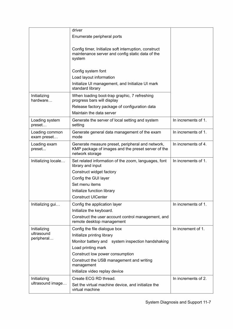
System Diagnosis and Support 11-7
driver Enumerate peripheral ports Config timer, Initialize soft interruption, construct maintenance server and config static data of the system Config system font Load layout information Initialize UI management, and Initialize UI mark standard library
Initializing hardware…
When loading boot-trap graphic, 7 refreshing progress bars will display Release factory package of configuration data Maintain the data server
Loading system preset…
Generate the server of local setting and system setting
In increments of 1.
Loading common exam preset…
Generate general data management of the exam mode
In increments of 1.
Loading exam preset...
Generate measure preset, peripheral and network, KMP package of images and the preset server of the network storage
In increments of 4.
Initializing locale… Set related information of the zoom, languages, font library and input Construct widget factory Config the GUI layer Set menu items Initialize function library Construct UICenter
In increments of 1.
Initializing gui… Config the application layer Initialize the keyboard. Construct the user account control management, and remote desktop management
In increments of 1.
Initializing ultrasound peripheral…
Config the file dialogue box Initialize printing library Monitor battery and system inspection handshaking Load printing mark Construct low power consumption Construct the USB management and writing management Initialize video replay device
In increment of 1.
Initializing ultrasound image…
Create ECG RD thread. Set the virtual machine device, and initialize the virtual machine
In increments of 2.
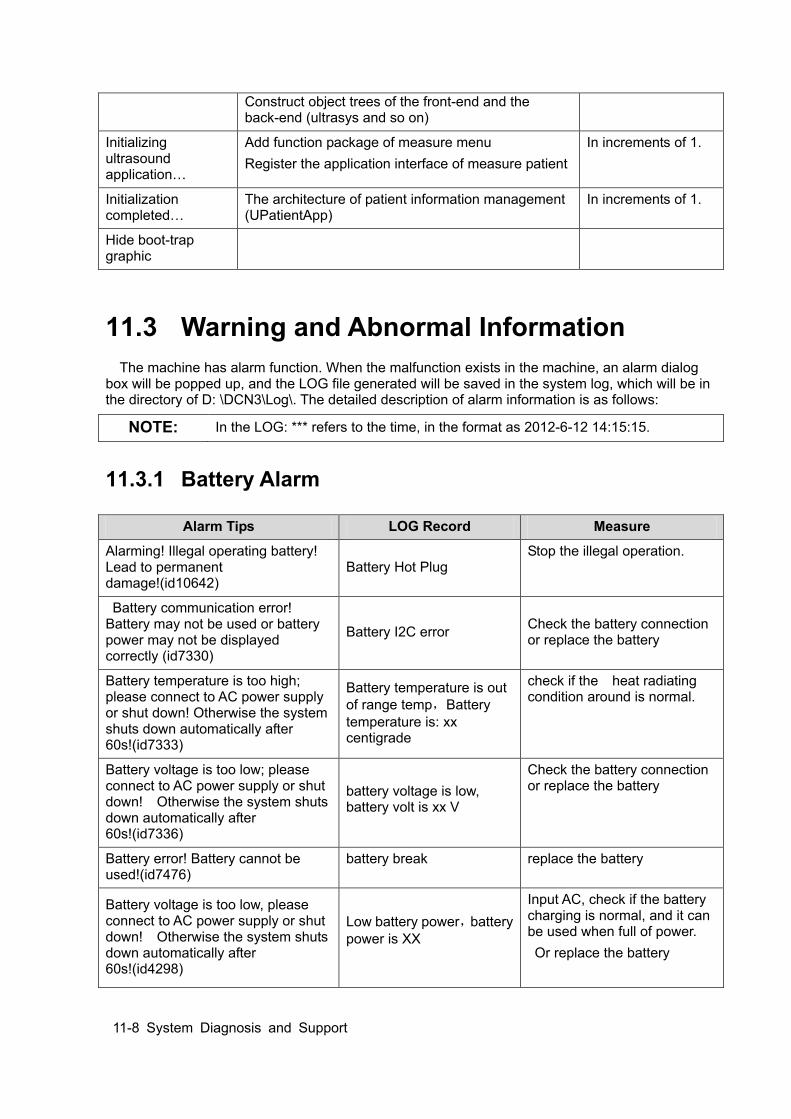
11-8 System Diagnosis and Support
Construct object trees of the front-end and the back-end (ultrasys and so on)
Initializing ultrasound application…
Add function package of measure menu Register the application interface of measure patient
In increments of 1.
Initialization completed…
The architecture of patient information management (UPatientApp)
In increments of 1.
Hide boot-trap graphic
11.3 Warning and Abnormal Information The machine has alarm function. When the malfunction exists in the machine, an alarm dialog
box will be popped up, and the LOG file generated will be saved in the system log, which will be in the directory of D: \DCN3\Log\. The detailed description of alarm information is as follows:
11.3.1 Battery Alarm
NOTE: In the LOG: *** refers to the time, in the format as 2012-6-12 14:15:15.
Alarm Tips LOG Record Measure
Alarming! Illegal operating battery! Lead to permanent damage!(id10642)
Battery Hot Plug Stop the illegal operation.
Battery communication error! Battery may not be used or battery power may not be displayed correctly (id7330)
Battery I2C error Check the battery connection or replace the battery
Battery temperature is too high; please connect to AC power supply or shut down! Otherwise the system shuts down automatically after 60s!(id7333)
Battery temperature is out of range temp,Battery temperature is: xx centigrade
check if the heat radiating condition around is normal.
Battery voltage is too low; please connect to AC power supply or shut down! Otherwise the system shuts down automatically after 60s!(id7336)
battery voltage is low, battery volt is xx V
Check the battery connection or replace the battery
Battery error! Battery cannot be used!(id7476)
battery break replace the battery
Battery voltage is too low, please connect to AC power supply or shut down! Otherwise the system shuts down automatically after 60s!(id4298)
Low battery power,battery power is XX
Input AC, check if the battery charging is normal, and it can be used when full of power. Or replace the battery
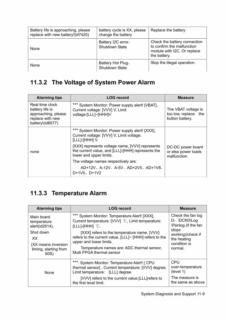
System Diagnosis and Support 11-9
11.3.2 The Voltage of System Power Alarm
11.3.3 Temperature Alarm
Battery life is approaching, please replace with new battery!(id7420)
battery cycle is XX, please change the battery
Replace the battery
None Battery I2C error,Shutdown State
Check the battery connection to confirm the malfunction module with I2C. Or replace the battery.
None Battery Hot Plug,Shutdown State
Stop the illegal operation.
Alarming tips LOG record Measure
Real time clock battery life is approaching, please replace with new battery!(id8577)
*** System Monitor: Power supply alert! [VBAT], Current voltage: [VVV] V, Limit voltage:[LLL]~[HHH]V
The VBAT voltage is too low, replace the button battery.
none
*** System Monitor: Power supply alert! [XXX], Current voltage: [VVV] V, Limit voltage: [LLL]-[HHH] V. [XXX] represents voltage name, [VVV] represents the current value, and [LLL]-[HHH] represents the lower and upper limits. The voltage names respectively are:
AD+12V、A-12V、A-5V、AD+2V5、AD+1V8、D+1V5、D+1V2
DC-DC power board or else power loads malfunction
Alarming tips LOG record Measure
Main board temperature alert(id2614), Shut down XX (XX means inversion timing, starting from
60S)
*** System Monitor: Temperature Alert! [XXX], Current temperature: [VVV] ℃, Limit temperature: [LLL]-[HHH] ℃.
[XXX] refers to the temperature name, [VVV] refers to the current value, [LLL]~ [HHH] refers to the upper and lower limits.
Temperature names are: ADC thermal sensor, Multi FPGA thermal sensor
Check the fan log D:\DCN3\Log \Perilog (if the fan stops working)/check if the heating condition is normal.
None
***: System Monitor: Temperature Alert! [ CPU thermal sensor] , Current temperature: [VVV] degree, Limit temperature: [LLL] degree
[VVV] refers to the current value.[LLL]refers to the first level limit.
CPU over-temperature (level 1) The measure is the same as above
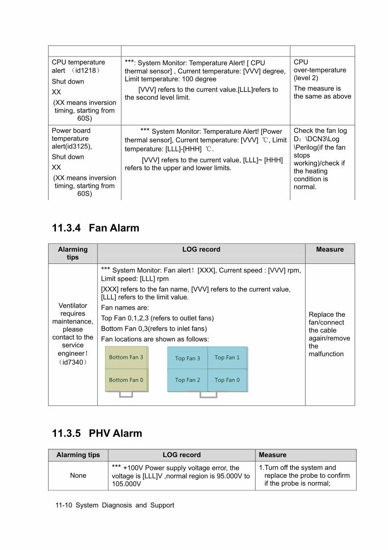
11-10 System Diagnosis and Support
11.3.4 Fan Alarm
11.3.5 PHV Alarm
CPU temperature alert (id1218) Shut down XX (XX means inversion timing, starting from
60S)
***: System Monitor: Temperature Alert! [ CPU thermal sensor] , Current temperature: [VVV] degree, Limit temperature: 100 degree
[VVV] refers to the current value.[LLL]refers to the second level limit.
CPU over-temperature (level 2) The measure is the same as above
Power board temperature alert(id3125), Shut down XX (XX means inversion timing, starting from
60S)
*** System Monitor: Temperature Alert! [Power thermal sensor], Current temperature: [VVV] ℃, Limit temperature: [LLL]-[HHH] ℃.
[VVV] refers to the current value, [LLL]~ [HHH] refers to the upper and lower limits.
Check the fan log D:\DCN3\Log \Perilog(if the fan stops working)/check if the heating condition is normal.
Alarming tips
LOG record Measure
Ventilator requires
maintenance, please
contact to the service
engineer!(id7340)
*** System Monitor: Fan alert![XXX], Current speed : [VVV] rpm, Limit speed: [LLL] rpm [XXX] refers to the fan name, [VVV] refers to the current value, [LLL] refers to the limit value. Fan names are: Top Fan 0,1,2,3 (refers to outlet fans) Bottom Fan 0,3(refers to inlet fans) Fan locations are shown as follows:
Bottom Fan 3
Bottom Fan 0
Top Fan 3
Top Fan 2
Top Fan 1
Top Fan 0
Replace the fan/connect the cable again/remove the malfunction
Alarming tips LOG record Measure
None *** +100V Power supply voltage error, the voltage is [LLL]V ,normal region is 95.000V to 105.000V
1. Turn off the system and replace the probe to confirm if the probe is normal;
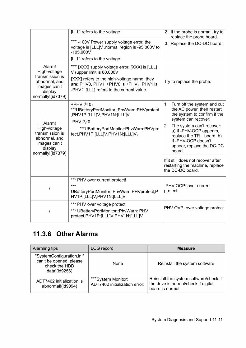
System Diagnosis and Support 11-11
11.3.6 Other Alarms
[LLL] refers to the voltage 2. If the probe is normal, try to replace the probe board.
3. Replace the DC-DC board. *** -100V Power supply voltage error, the voltage is [LLL]V ,normal region is -95.000V to -105.000V [LLL] refers to the voltage
Alarm! High-voltage
transmission is abnormal, and images can’t
display normally!(id7379)
*** [XXX] supply voltage error, [XXX] is [LLL] V (upper limit is 80.000V [XXX] refers to the high-voltage name, they are: PHV0, PHV1(PHV0 is +PHV,PHV1 is -PHV)[LLL] refers to the current value.
Try to replace the probe.
Alarm! High-voltage
transmission is abnormal, and images can’t
display normally!(id7379)
+PHV 为 0:***UBatteryPortMonitor::PhvWarn:PHVprotect,PHV1P:[LLL]V,PHV1N:[LLL]V -PHV 为 0:
***UBatteryPortMonitor:PhvWarn:PHVprotect,PHV1P:[LLL]V,PHV1N:[LLL]V。
1. Turn off the system and cut the AC power, then restart the system to confirm if the system can recover;
2. The system can’t recover: a).If -PHV-OCP appears, replace the TR board. b). If -PHV-OCP doesn’t appear, replace the DC-DC board.
If it still does not recover after restarting the machine, replace the DC-DC board.
/
*** PHV over current protect! *** UBatteryPortMonitor::PhvWarn:PHVprotect,PHV1P:[LLL]V,PHV1N:[LLL]V
-PHV-OCP: over current protect.
/ *** PHV over voltage protect! *** UBatteryPortMonitor::PhvWarn: PHV protect,PHV1P:[LLL]V,PHV1N:[LLL]V
PHV-OVP: over voltage protect
Alarming tips LOG record Measure
"SystemConfiguration.ini" can’t be opened, please
check the HDD data!(id9256)
None Reinstall the system software
ADT7462 initialization is abnormal!(id9094)
***System Monitor: ADT7462 initialization error:
Reinstall the system software/check if the drive is normal/check if digital board is normal


Care & Maintenance 12-1
12 Care & Maintenance
12.1 Overview These procedures in this chapter are recommended.
12.1.1 Tools, Measurement Devices and Consumables Table 12-1 Tools and Measurement Devices
Tool/Measurement Devices Qty. Remarks
Resin or plastic container 1 pcs Can accommodate two probes
Soft brush 1 pcs About a toothbrush size
Small plastic basin 1 pcs Used to fill the soapy water
Safety test analyzer 1 pcs Refer to appendix A
Inner hexagon wrench 1pcs Inner hexagon wrench 6 #
Solid wrench 1pcs With opening diameters of 36mm
Cross-headed screwdriver 1pcs 105 X100
Table 12-2 Consumable List
12.1.2 Care and Maintenance Items
Consumable Qty. Remarks
Aluminum foil About 1 meter
Physiological saline About 1000ml Filling a half container Immerging the whole probe (referring to appendix A). (concentration 0.85 ~ 0.95%)
Mild soapy water About 400ml
Dry soft cloth/cotton cloth About 5 pcs
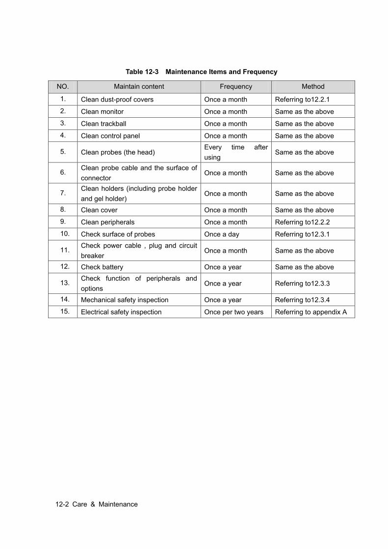
12-2 Care & Maintenance
Table 12-3 Maintenance Items and Frequency
NO. Maintain content Frequency Method
1. Clean dust-proof covers Once a month Referring to12.2.1
2. Clean monitor Once a month Same as the above
3. Clean trackball Once a month Same as the above
4. Clean control panel Once a month Same as the above
5. Clean probes (the head) Every time after using
Same as the above
6. Clean probe cable and the surface of connector
Once a month Same as the above
7. Clean holders (including probe holder and gel holder)
Once a month Same as the above
8. Clean cover Once a month Same as the above
9. Clean peripherals Once a month Referring to12.2.2
10. Check surface of probes Once a day Referring to12.3.1
11. Check power cable , plug and circuit breaker
Once a month Same as the above
12. Check battery Once a year Same as the above
13. Check function of peripherals and options
Once a year Referring to12.3.3
14. Mechanical safety inspection Once a year Referring to12.3.4
15. Electrical safety inspection Once per two years Referring to appendix A
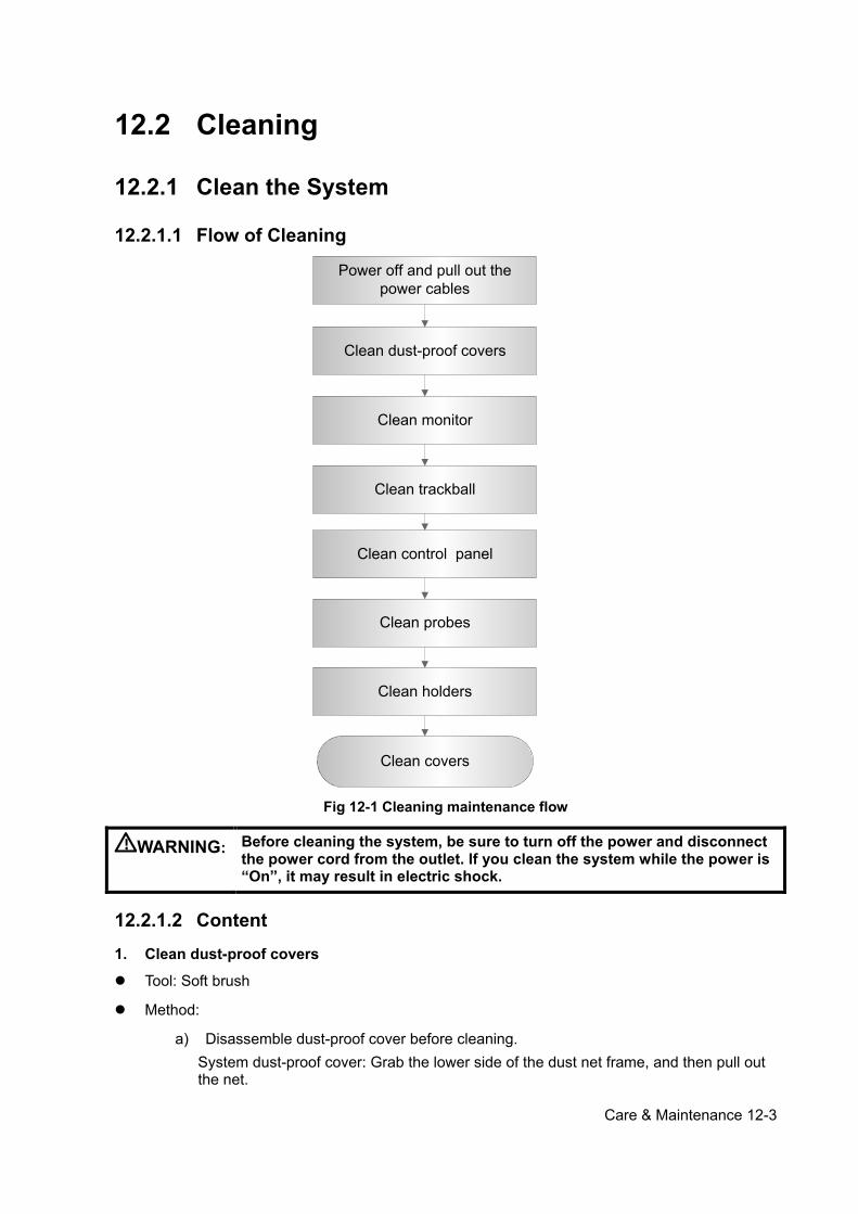
Care & Maintenance 12-3
12.2 Cleaning
12.2.1 Clean the System
12.2.1.1 Flow of Cleaning
Clean dust-proof covers
Clean monitor
Clean trackball
Clean holders
Clean covers
Clean probes
Clean control panel
Power off and pull out the power cables
Fig 12-1 Cleaning maintenance flow
WARNING: Before cleaning the system, be sure to turn off the power and disconnect the power cord from the outlet. If you clean the system while the power is “On”, it may result in electric shock.
12.2.1.2 Content 1. Clean dust-proof covers
Tool: Soft brush
Method:
a) Disassemble dust-proof cover before cleaning. System dust-proof cover: Grab the lower side of the dust net frame, and then pull out the net.

12-4 Care & Maintenance
Probe port dust-proof cover: there is a probe port dust-proof cover at the front of the system, Pull it out.
b) Cleaning: with soft brush and then wipe off the dust. c) Assemble dust-proof covers.
Input the dust-proof clasp into the slot of the main unit, push the dust-proof inward until the dust-proof clasp is blocked in the slot.
CAUTION: Please clean all dust-proof covers of the system periodically (1 time per month); otherwise, system damage may result. Cleaning times can be increased when the system is used in the open air or somewhere dust is more.
2. Clean Monitor
Tool: soft dry cloth ,clear water or soapy water
Method:
Surface of monitor and should be cleaned with soft dry cloth directly. Remained stain should be washed out by cloth with a little clear water or soapy water, and then air-dry the surface.
3. Clean Trackball
Tool: Dry soft cloth, soapy water
Method:
a) Disassemble Press the bulges on the clamping ring by both hands and turn the ring about 45°clockwise until it lifts. Take out the ring and the rotary ball. Be careful not to drop the ball. Shown as follows:
b) Cleaning
Top cover
Rotary ball
Clamping ring
Dust-proof
Main unit
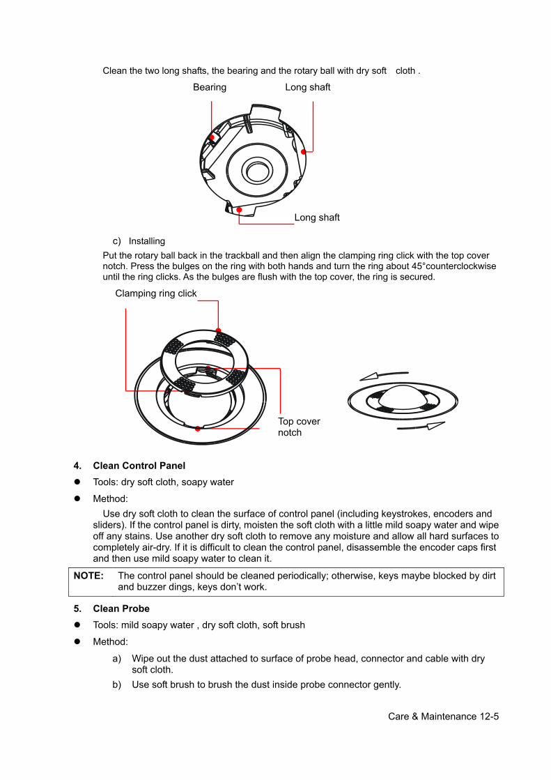
Care & Maintenance 12-5
Clean the two long shafts, the bearing and the rotary ball with dry soft cloth .
c) Installing
Put the rotary ball back in the trackball and then align the clamping ring click with the top cover notch. Press the bulges on the ring with both hands and turn the ring about 45°counterclockwise until the ring clicks. As the bulges are flush with the top cover, the ring is secured.
4. Clean Control Panel Tools: dry soft cloth, soapy water
Method: Use dry soft cloth to clean the surface of control panel (including keystrokes, encoders and sliders). If the control panel is dirty, moisten the soft cloth with a little mild soapy water and wipe off any stains. Use another dry soft cloth to remove any moisture and allow all hard surfaces to completely air-dry. If it is difficult to clean the control panel, disassemble the encoder caps first and then use mild soapy water to clean it.
NOTE: The control panel should be cleaned periodically; otherwise, keys maybe blocked by dirt and buzzer dings, keys don’t work.
5. Clean Probe Tools: mild soapy water , dry soft cloth, soft brush
Method:
a) Wipe out the dust attached to surface of probe head, connector and cable with dry soft cloth.
b) Use soft brush to brush the dust inside probe connector gently.
Long shaft
Bearing Long shaft
Clamping ring click
Top cover notch
12-6 Care & Maintenance
c) Remained stain or dust attached to surface of cable or surface of connector should be washed out by cloth with a little soapy water, and then air-dry.
NOTE: Don’t use cloth with water to clean the probe connector.
6. Clean Holders
Tool: dry soft cloth , soapy water, soft brush
Method:
a) Use dry soft cloth to wipe off the dust attached to inside, outside or gap of probe holder or gel holder. As to small intra-cavity probe holder or its gap, use the soft brush to brush the dust or stain.
b) Remained stain attached to inside, outside of holder should be washed out by cloth with a little soapy water after it was taken out, and then install the holder after air-dry.
7. Clean Cover Tools: dry soft cloth, soapy water
Method: Use dry soft cloth to clean the cover of the system. If the system is dirty, moisten the soft cloth with mild soapy water and wipe off any stains, then air-dry. Note: Be sure to use soft brush to brush the dust attached to all the sockets or interfaces which can be seen (such as probe sockets, sockets or interfaces in IO panel and power supply panel),not the cloth with water.
12.2.2 Clean the Peripherals Do the cleaning maintenance according to your actual peripheral configuration; items which are not configured can be skipped.
Table 12-4 Peripherals Cleaning List
No. Content Description
1. Color and B/W video printer
First wipe off dust or stain attached to the cover of printer with soft dry cloth, then clean the inside of printer. Be sure to do the cleaning maintenance according to the operation manual if is necessary.
2. Graph / text printer
First wipe off dust or stain attached to the cover of printer with soft dry cloth, then clean the inside of printer. Be sure to do the cleaning maintenance according to the operation manual if is necessary.
3. Foot switch Use soft dry cloth with a little mild soap water to wipe off the dust or stain attached to the pedals or cable of foot switch.
4. Bar code scanner
First use soft dry cloth to wipe off dust attached to glass panel of scanner, then the dust or strain attached to cable and bracket. Be sure to do the especial cleaning maintenance according to the operation manual if is necessary.
Care & Maintenance 12-7
12.3 Checking
12.3.1 General check Table 12-5 General check list
No. Content Method
1. Probe
a) Visually check to confirm that there is no crack and expansion to probe head.
b) Visually check to confirm that there is no deterioration or desquamation to probe cable.
c) Visually check to confirm that there is no bend, destroyed or falling off pins to the connector
2.
Power supply
cable and plug
a) Visually check to confirm that there is no wrinkles, crack or deterioration
b) Manually check to confirm that there is no looseness or rupture to cable. The connection of plug is reliable and the retaining clamp of power supply cable is effective.
3. Battery
Check the battery periodically : a) Check if battery can be charged normally when power-on: That the
current capacity is 100% or capacity increases after a short time indicates that the battery can be charged normally. It takes less than 2 minutes to increase 1% capacity when the total capacity is less than 90% and it takes more time when the capacity is more than 90%.
b) Disconnect the system from the AC power supply to confirm if the system can maintain normal work status in the battery power supply.
12.3.2 System Function Check The system function checking is not required during Preventive Maintenance. Engineer or Customer may use it as part of their product Quality Assurance Program tests。
Table 12-6 System function list
No. Content Method
1. B mode Verify basic operation of B mode. Check basic software and hardware controls affecting B mode operations.
2. Color mode Verify basic operation of Color mode. Check basic software and hardware controls affecting Color mode operations.
3. Doppler mode (PW/CW) Verify basic operation of Doppler mode. Check basic software and hardware controls affecting Doppler mode operations.
4. M mode Verify basic operation of M mode. Check basic software and hardware controls affecting M mode operations.

12-8 Care & Maintenance
No. Content Method
5.
Measurement(2D, M, Doppler general measurement, optional applied measurement )
Scanning gray scale imaging on phantom, verify distance and area accuracy with measurement control. Verify measurement accuracy by performance test.
6. Keyboard test Operate keyboard test to verify if all control keys can work normally.
7. LCD Verify LCD display function and parameters adjustment. Refer to that of LCD checking.
8. Software menu check Verify software menu display function: if each operation menu and page can be accessed.
Remark:Please refer to 5.4~5.5 for details.
12.3.3 Peripherals and Options Check If the system is not configured with any module or peripheral, the corresponding items checking can be skipped.
Table 12-7 Options, Peripherals and Accessories Check list
No. Content Method
1. Color and B/W video printer
Check if the output of video printer is normal.
2. Graph / text printer Check if the output of graph / text printer is normal.
3. Foot switch Check if the foot switch can implement the set functions according to the program.
4. DVD-R/W Check if DVD can work normally (write, read and pop).
5. Bar code scanner Check if the scanner can work normally and the output content is right.
6. DICOM Check if DICOM can work normally and send pictures and other data to DICOM server.
7. ECG module Check basic operations and verify the implementation of ECG functions.
Remark:Please refer to 5.3 for details.
12.3.4 Mechanical Safety Inspection Mechanical safety inspection is mainly used to check mechanical strength and mechanical
function of the key assembly of ultrasonic system. The mode of test evaluation mainly is: Perform the evaluation by means of visual check and operating check, if the check result cannot pass, the system is in abnormal status now. Stop using the system and adopt proper measures. The test flow is as following:
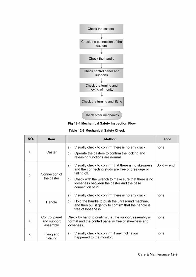
Care & Maintenance 12-9
Check the handle
Check control panel And supports
Check the turning and moving of monitor
Check other mechanics
Check the connection of the casters
Check the casters
Check the turning and lifting
Fig 12-4 Mechanical Safety Inspection Flow
Table 12-8 Mechanical Safety Check
NO. Item Method Tool
1. Caster a) Visually check to confirm there is no any crack.
b) Operate the casters to confirm the locking and releasing functions are normal.
none
2. Connection of the caster
a) Visually check to confirm that there is no skewness and the connecting studs are free of breakage or falling off.
b) Check with the wrench to make sure that there is no looseness between the caster and the base connection stud.
Solid wrench
3. Handle
a) Visually check to confirm there is no any crack.
b) Hold the handle to push the ultrasound machine, and then pull it gently to confirm that the handle is free of looseness.
none
4. Control panel and support assembly
Check by hand to confirm that the support assembly is normal and the control panel is free of skewness and looseness.
none
5. Fixing and rotating
a) Visually check to confirm if any inclination happened to the monitor.
none
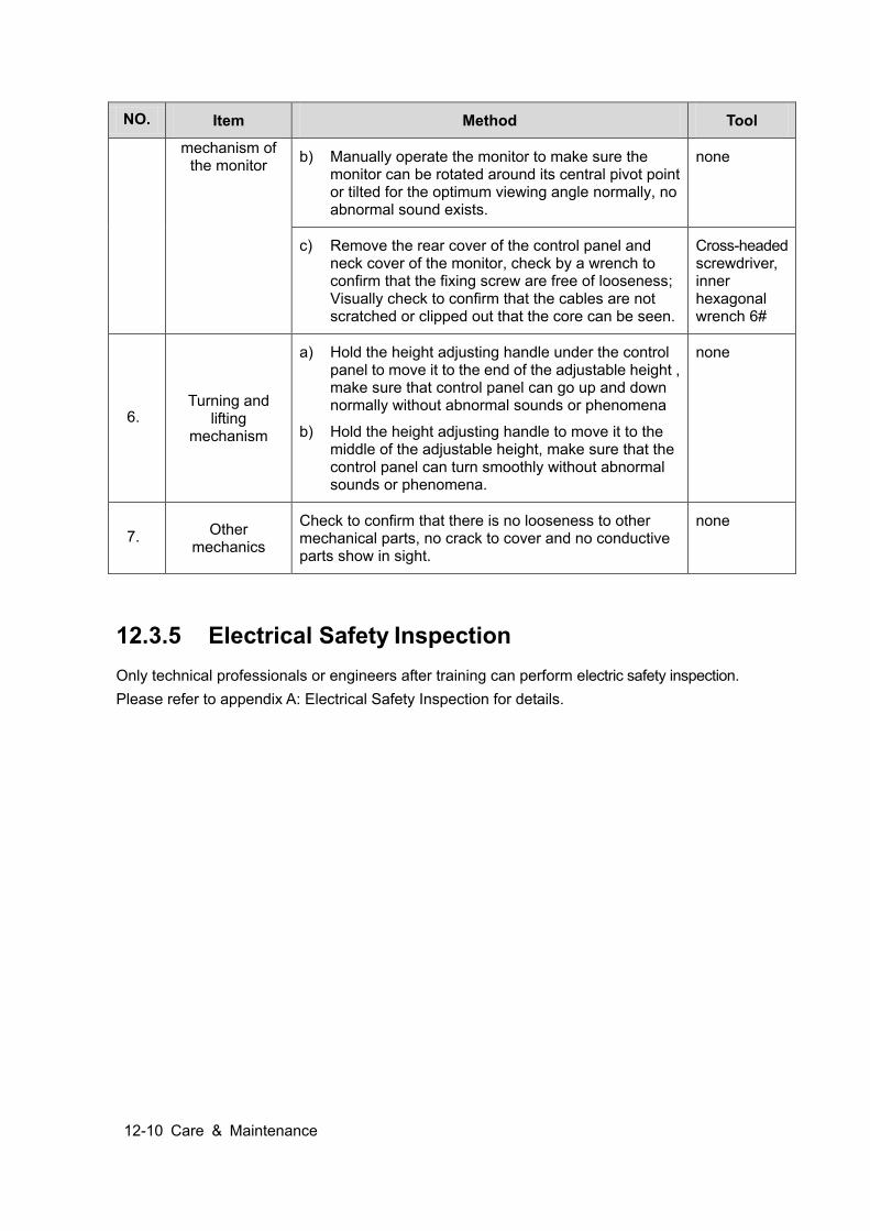
12-10 Care & Maintenance
NO. Item Method Tool
mechanism of the monitor b) Manually operate the monitor to make sure the
monitor can be rotated around its central pivot point or tilted for the optimum viewing angle normally, no abnormal sound exists.
none
c) Remove the rear cover of the control panel and neck cover of the monitor, check by a wrench to confirm that the fixing screw are free of looseness; Visually check to confirm that the cables are not scratched or clipped out that the core can be seen.
Cross-headed screwdriver, inner hexagonal wrench 6#
6. Turning and
lifting mechanism
a) Hold the height adjusting handle under the control panel to move it to the end of the adjustable height , make sure that control panel can go up and down normally without abnormal sounds or phenomena
b) Hold the height adjusting handle to move it to the middle of the adjustable height, make sure that the control panel can turn smoothly without abnormal sounds or phenomena.
none
7. Other mechanics
Check to confirm that there is no looseness to other mechanical parts, no crack to cover and no conductive parts show in sight.
none
12.3.5 Electrical Safety Inspection Only technical professionals or engineers after training can perform electric safety inspection. Please refer to appendix A: Electrical Safety Inspection for details.
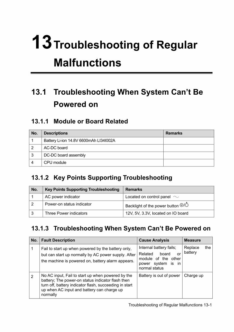
Troubleshooting of Regular Malfunctions 13-1
13 Troubleshooting of Regular Malfunctions
13.1 Troubleshooting When System Can’t Be Powered on
13.1.1 Module or Board Related
No. Descriptions Remarks
1 Battery Li-ion 14.8V 6600mAh LI34I002A
2 AC-DC board
3 DC-DC board assembly
4 CPU module
13.1.2 Key Points Supporting Troubleshooting
No. Key Points Supporting Troubleshooting Remarks
1 AC power indicator Located on control panel
2 Power-on status indicator Backlight of the power button
3 Three Power indicators 12V, 5V, 3.3V, located on IO board
13.1.3 Troubleshooting When System Can’t Be Powered on
No. Fault Description Cause Analysis Measure
1 Fail to start up when powered by the battery only, but can start up normally by AC power supply. After the machine is powered on, battery alarm appears.
Internal battery fails; Related board or module of the other power system is in normal status
Replace the battery
2 No AC input, Fail to start up when powered by the battery; The power-on status indicator flash then turn off, battery indicator flash, succeeding in start up when AC input and battery can charge up normally
Battery is out of power Charge up
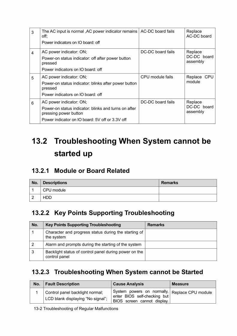
13-2 Troubleshooting of Regular Malfunctions
3 The AC input is normal ,AC power indicator remains off; Power indicators on IO board: off
AC-DC board fails Replace AC-DC board
4 AC power indicator: ON; Power-on status indicator: off after power button pressed Power indicators on IO board: off
DC-DC board fails Replace DC-DC board assembly
5 AC power indicator: ON; Power-on status indicator: blinks after power button pressed Power indicators on IO board: off
CPU module fails Replace CPU module
6 AC power indicator: ON; Power-on status indicator: blinks and turns on after pressing power button Power indicator on IO board: 5V off or 3.3V off
DC-DC board fails Replace DC-DC board assembly
13.2 Troubleshooting When System cannot be started up
13.2.1 Module or Board Related
No. Descriptions Remarks
1 CPU module
2 HDD
13.2.2 Key Points Supporting Troubleshooting
No. Key Points Supporting Troubleshooting Remarks
1 Character and progress status during the starting of the system
2 Alarm and prompts during the starting of the system
3 Backlight status of control panel during power on the control panel
13.2.3 Troubleshooting When System cannot be Started
No. Fault Description Cause Analysis Measure
1 Control panel backlight normal; LCD blank displaying “No signal”;
System powers on normally, enter BIOS self-checking but BIOS screen cannot display.
Replace CPU module
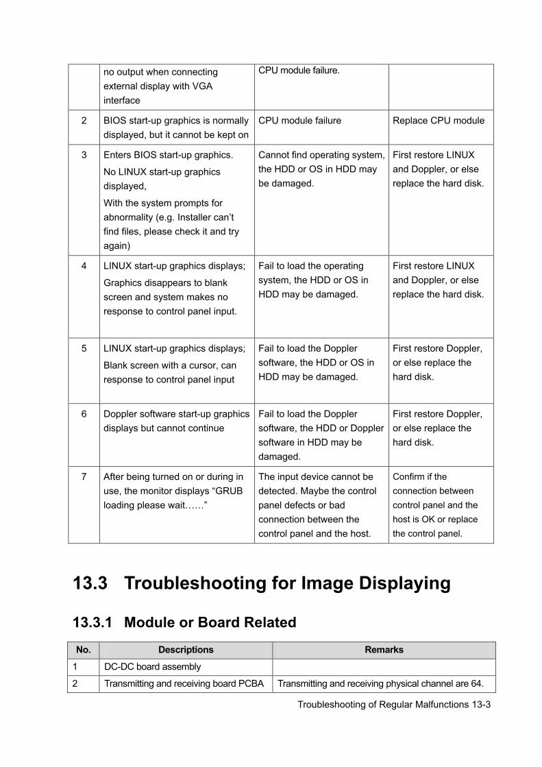
Troubleshooting of Regular Malfunctions 13-3
no output when connecting external display with VGA interface
CPU module failure.
2 BIOS start-up graphics is normally displayed, but it cannot be kept on
CPU module failure Replace CPU module
3 Enters BIOS start-up graphics.
No LINUX start-up graphics displayed,
With the system prompts for abnormality (e.g. Installer can’t find files, please check it and try again)
Cannot find operating system, the HDD or OS in HDD may be damaged.
First restore LINUX and Doppler, or else replace the hard disk.
4 LINUX start-up graphics displays;
Graphics disappears to blank screen and system makes no response to control panel input.
Fail to load the operating system, the HDD or OS in HDD may be damaged.
First restore LINUX and Doppler, or else replace the hard disk.
5 LINUX start-up graphics displays;
Blank screen with a cursor, can response to control panel input
Fail to load the Doppler software, the HDD or OS in HDD may be damaged.
First restore Doppler, or else replace the hard disk.
6 Doppler software start-up graphics displays but cannot continue
Fail to load the Doppler software, the HDD or Doppler software in HDD may be damaged.
First restore Doppler, or else replace the hard disk.
7 After being turned on or during in use, the monitor displays “GRUB loading please wait……”
The input device cannot be detected. Maybe the control panel defects or bad connection between the control panel and the host.
Confirm if the connection between control panel and the host is OK or replace the control panel.
13.3 Troubleshooting for Image Displaying
13.3.1 Module or Board Related
No. Descriptions Remarks
1 DC-DC board assembly
2 Transmitting and receiving board PCBA Transmitting and receiving physical channel are 64.
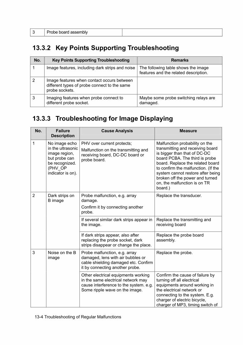
13-4 Troubleshooting of Regular Malfunctions
3 Probe board assembly
13.3.2 Key Points Supporting Troubleshooting
No. Key Points Supporting Troubleshooting Remarks
1 Image features, including dark strips and noise The following table shows the image features and the related description.
2 Image features when contact occurs between different types of probe connect to the same probe sockets.
3 Imaging features when probe connect to different probe socket.
Maybe some probe switching relays are damaged.
13.3.3 Troubleshooting for Image Displaying
No. Failure Description
Cause Analysis Measure
1 No image echo in the ultrasonic image region, but probe can be recognized. (PHV_OP indicator is on).
PHV over current protects; Malfunction on the transmitting and receiving board, DC-DC board or probe board.
Malfunction probability on the transmitting and receiving board is bigger than that of DC-DC board PCBA. The third is probe board. Replace the related board to confirm the malfunction. (If the system cannot restore after being broken off the power and turned on, the malfunction is on TR board.)
2 Dark strips on B image
Probe malfunction, e.g. array damage. Confirm it by connecting another probe.
Replace the transducer.
If several similar dark strips appear in the image.
Replace the transmitting and receiving board
If dark strips appear, also after replacing the probe socket, dark strips disappear or change the place.
Replace the probe board assembly.
3 Noise on the B image
Probe malfunction, e.g. array damaged, lens with air bubbles or cable shielding damaged etc. Confirm it by connecting another probe.
Replace the probe.
Other electrical equipments working in the same electrical network may cause interference to the system. e.g. Some ripple wave on the image.
Confirm the cause of failure by turning off all electrical equipments around working in the electrical network or connecting to the system. E.g. charger of electric bicycle, charger of MP3, timing switch of
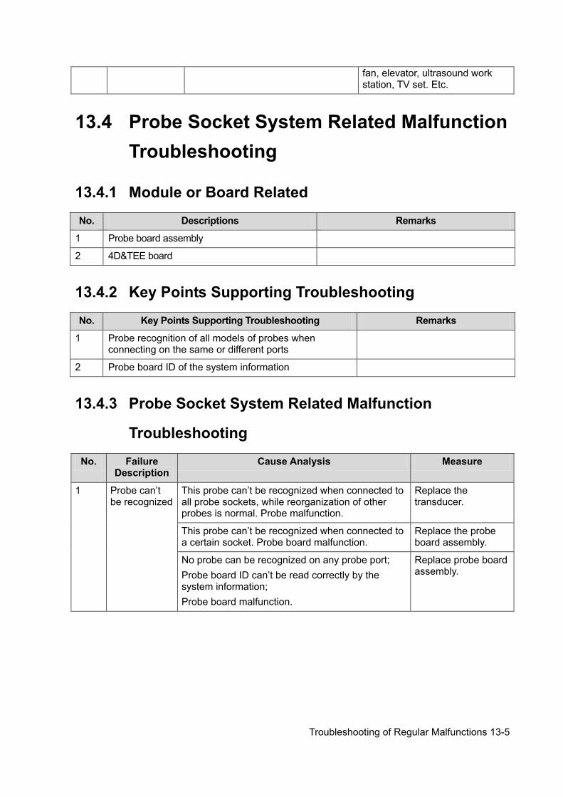
Troubleshooting of Regular Malfunctions 13-5
fan, elevator, ultrasound work station, TV set. Etc.
13.4 Probe Socket System Related Malfunction Troubleshooting
13.4.1 Module or Board Related
No. Descriptions Remarks
1 Probe board assembly
2 4D&TEE board
13.4.2 Key Points Supporting Troubleshooting
No. Key Points Supporting Troubleshooting Remarks
1 Probe recognition of all models of probes when connecting on the same or different ports
2 Probe board ID of the system information
13.4.3 Probe Socket System Related Malfunction
Troubleshooting
No. Failure Description
Cause Analysis Measure
1 Probe can’t be recognized
This probe can’t be recognized when connected to all probe sockets, while reorganization of other probes is normal. Probe malfunction.
Replace the transducer.
This probe can’t be recognized when connected to a certain socket. Probe board malfunction.
Replace the probe board assembly.
No probe can be recognized on any probe port; Probe board ID can’t be read correctly by the system information; Probe board malfunction.
Replace probe board assembly.
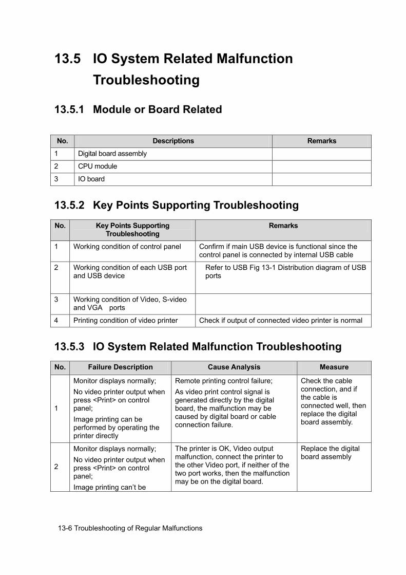
13-6 Troubleshooting of Regular Malfunctions
13.5 IO System Related Malfunction Troubleshooting
13.5.1 Module or Board Related
No. Descriptions Remarks
1 Digital board assembly
2 CPU module
3 IO board
13.5.2 Key Points Supporting Troubleshooting
No. Key Points Supporting Troubleshooting
Remarks
1 Working condition of control panel Confirm if main USB device is functional since the control panel is connected by internal USB cable
2 Working condition of each USB port and USB device
Refer to USB Fig 13-1 Distribution diagram of USB ports
3 Working condition of Video, S-video and VGA ports
4 Printing condition of video printer Check if output of connected video printer is normal
13.5.3 IO System Related Malfunction Troubleshooting
No. Failure Description Cause Analysis Measure
1
Monitor displays normally; No video printer output when press <Print> on control panel; Image printing can be performed by operating the printer directly
Remote printing control failure; As video print control signal is generated directly by the digital board, the malfunction may be caused by digital board or cable connection failure.
Check the cable connection, and if the cable is connected well, then replace the digital board assembly.
2
Monitor displays normally; No video printer output when press <Print> on control panel; Image printing can’t be
The printer is OK, Video output malfunction, connect the printer to the other Video port, if neither of the two port works, then the malfunction may be on the digital board.
Replace the digital board assembly
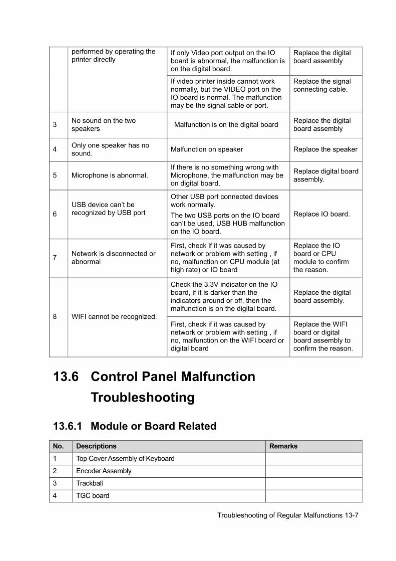
Troubleshooting of Regular Malfunctions 13-7
performed by operating the printer directly
If only Video port output on the IO board is abnormal, the malfunction is on the digital board.
Replace the digital board assembly
If video printer inside cannot work normally, but the VIDEO port on the IO board is normal. The malfunction may be the signal cable or port.
Replace the signal connecting cable.
3 No sound on the two speakers Malfunction is on the digital board Replace the digital
board assembly
4 Only one speaker has no sound. Malfunction on speaker Replace the speaker
5 Microphone is abnormal. If there is no something wrong with Microphone, the malfunction may be on digital board.
Replace digital board assembly.
6 USB device can’t be recognized by USB port
Other USB port connected devices work normally. The two USB ports on the IO board can’t be used, USB HUB malfunction on the IO board.
Replace IO board.
7 Network is disconnected or abnormal
First, check if it was caused by network or problem with setting , if no, malfunction on CPU module (at high rate) or IO board
Replace the IO board or CPU module to confirm the reason.
8 WIFI cannot be recognized.
Check the 3.3V indicator on the IO board, if it is darker than the indicators around or off, then the malfunction is on the digital board.
Replace the digital board assembly.
First, check if it was caused by network or problem with setting , if no, malfunction on the WIFI board or digital board
Replace the WIFI board or digital board assembly to confirm the reason.
13.6 Control Panel Malfunction Troubleshooting
13.6.1 Module or Board Related
No. Descriptions Remarks
1 Top Cover Assembly of Keyboard
2 Encoder Assembly
3 Trackball
4 TGC board
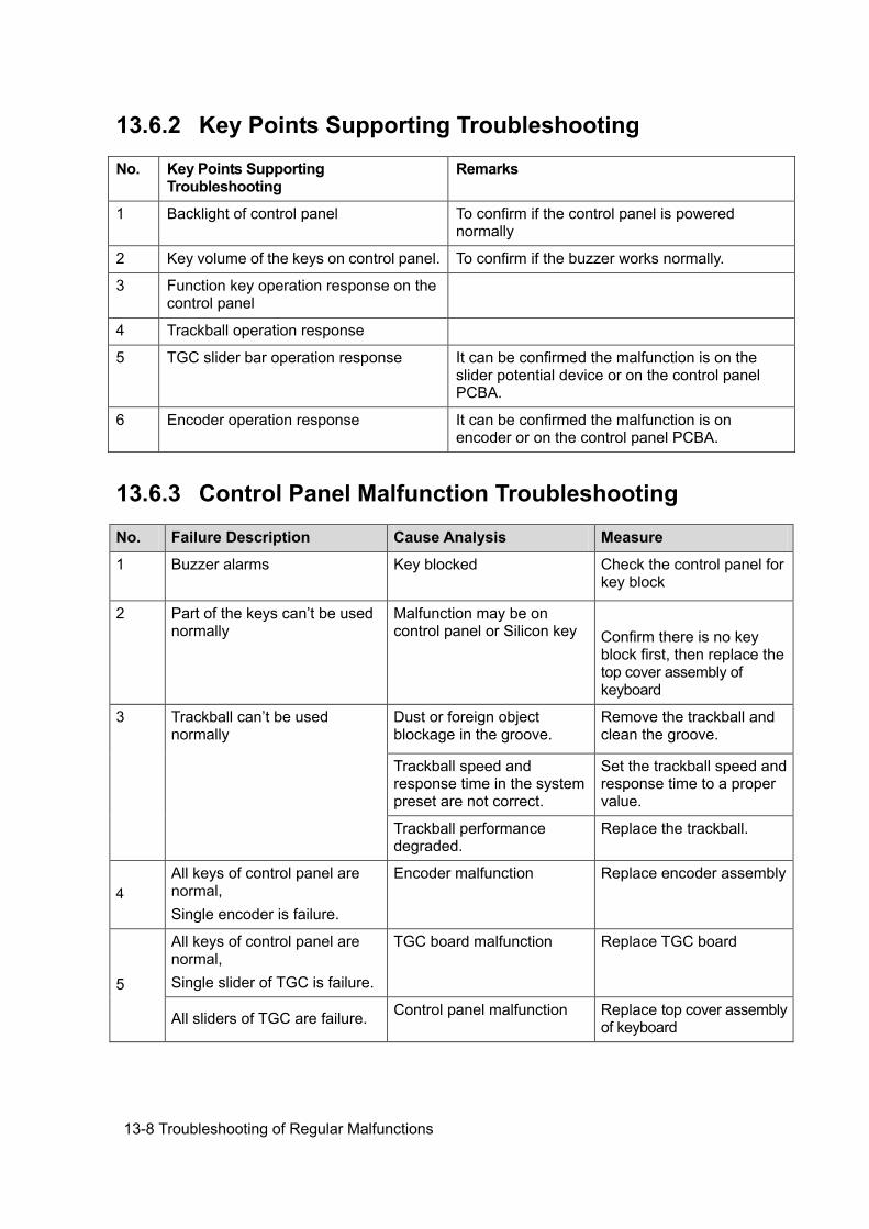
13-8 Troubleshooting of Regular Malfunctions
13.6.2 Key Points Supporting Troubleshooting
No. Key Points Supporting Troubleshooting
Remarks
1 Backlight of control panel To confirm if the control panel is powered normally
2 Key volume of the keys on control panel. To confirm if the buzzer works normally.
3 Function key operation response on the control panel
4 Trackball operation response
5 TGC slider bar operation response It can be confirmed the malfunction is on the slider potential device or on the control panel PCBA.
6 Encoder operation response It can be confirmed the malfunction is on encoder or on the control panel PCBA.
13.6.3 Control Panel Malfunction Troubleshooting
No. Failure Description Cause Analysis Measure
1 Buzzer alarms Key blocked Check the control panel for key block
2 Part of the keys can’t be used normally
Malfunction may be on control panel or Silicon key
Confirm there is no key block first, then replace the top cover assembly of keyboard
3 Trackball can’t be used normally
Dust or foreign object blockage in the groove.
Remove the trackball and clean the groove.
Trackball speed and response time in the system preset are not correct.
Set the trackball speed and response time to a proper value.
Trackball performance degraded.
Replace the trackball.
4 All keys of control panel are normal, Single encoder is failure.
Encoder malfunction Replace encoder assembly
5
All keys of control panel are normal, Single slider of TGC is failure.
TGC board malfunction Replace TGC board
All sliders of TGC are failure. Control panel malfunction Replace top cover assembly of keyboard
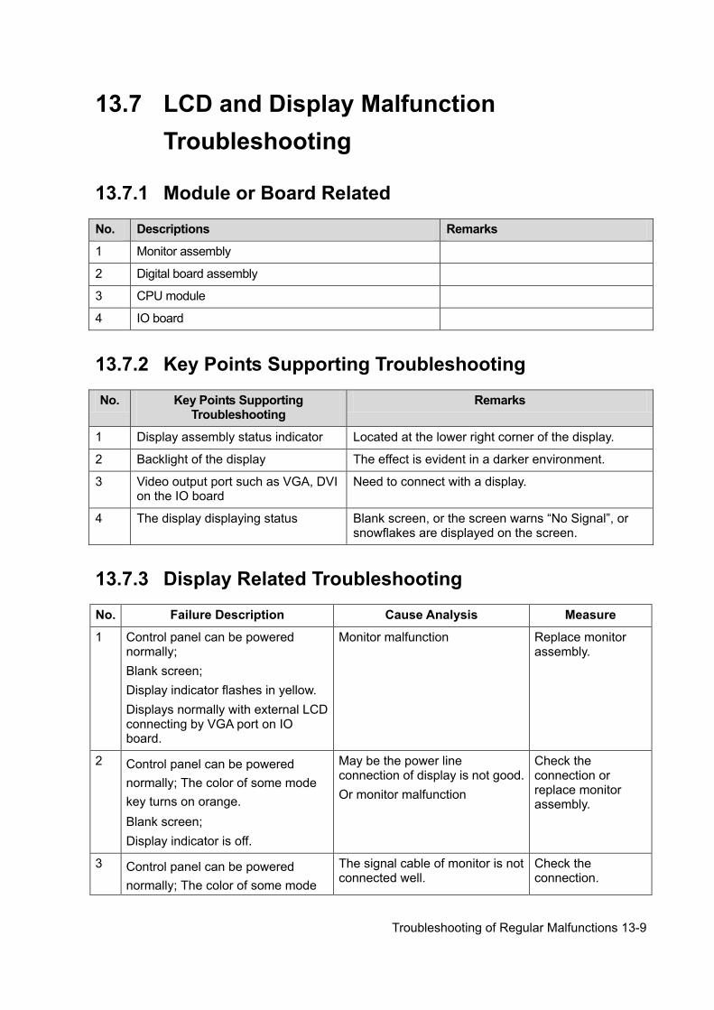
Troubleshooting of Regular Malfunctions 13-9
13.7 LCD and Display Malfunction Troubleshooting
13.7.1 Module or Board Related
No. Descriptions Remarks
1 Monitor assembly
2 Digital board assembly
3 CPU module
4 IO board
13.7.2 Key Points Supporting Troubleshooting
No. Key Points Supporting Troubleshooting
Remarks
1 Display assembly status indicator Located at the lower right corner of the display.
2 Backlight of the display The effect is evident in a darker environment.
3 Video output port such as VGA, DVI on the IO board
Need to connect with a display.
4 The display displaying status Blank screen, or the screen warns “No Signal”, or snowflakes are displayed on the screen.
13.7.3 Display Related Troubleshooting
No. Failure Description Cause Analysis Measure
1 Control panel can be powered normally; Blank screen; Display indicator flashes in yellow. Displays normally with external LCD connecting by VGA port on IO board.
Monitor malfunction Replace monitor assembly.
2 Control panel can be powered normally; The color of some mode key turns on orange. Blank screen; Display indicator is off.
May be the power line connection of display is not good. Or monitor malfunction
Check the connection or replace monitor assembly.
3 Control panel can be powered normally; The color of some mode
The signal cable of monitor is not connected well.
Check the connection.
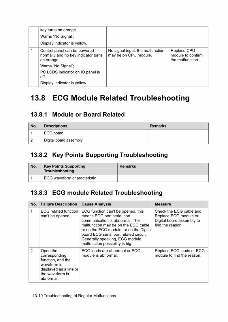
13-10 Troubleshooting of Regular Malfunctions
key turns on orange. Warns “No Signal”;
Display indicator is yellow.
4 Control panel can be powered normally and no key indicator turns on orange. Warns “No Signal”; PC LCDS indicator on IO panel is off. Display indicator is yellow.
No signal input, the malfunction may be on CPU module.
Replace CPU module to confirm the malfunction.
13.8 ECG Module Related Troubleshooting
13.8.1 Module or Board Related
No. Descriptions Remarks
1 ECG board
2 Digital board assembly
13.8.2 Key Points Supporting Troubleshooting
No. Key Points Supporting Troubleshooting
Remarks
1 ECG waveform characteristic
13.8.3 ECG module Related Troubleshooting
No. Failure Description Cause Analysis Measure
1 ECG related function can’t be opened.
ECG function can’t be opened, this means ECG port serial port communication is abnormal. The malfunction may be on the ECG cable, or on the ECG module, or on the Digital board ECG serial port related circuit. Generally speaking, ECG module malfunction possibility is big.
Check the ECG cable and Replace ECG module or Digital board assembly to find the reason.
2 Open the corresponding function, and the waveform is displayed as a line or the waveform is abnormal.
ECG leads are abnormal or ECG module is abnormal.
Replace ECG leads or ECG module to find the reason.

Electrical Safety Inspection A-1
Appendix A Electrical Safety Inspection
The following electrical safety tests are recommended as part of a comprehensive preventive maintenance program. They are a proven means of detecting abnormalities that, if undetected, could prove dangerous to either the patient or the operator. Additional tests may be required according to local regulations. All tests can be performed using commercially available safety analyzer test equipment. These procedures assume the use of a 601PROXL International Safety Analyzer or equivalent safety analyzer. Other popular testers complying with IEC 60601-1 used in Europe such as Fluke, Metron, or Gerb may require modifications to the procedure. Follow the instructions of the analyzer manufacturer.
The consistent use of a safety analyzer as a routine step in closing a repair or upgrade is emphasized as a mandatory step if an approved agency status is to be maintained. The safety analyzer also proves to be an excellent troubleshooting tool to detect abnormalities of line voltage and grounding, as well as total current loads.
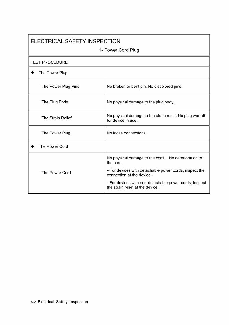
A-2 Electrical Safety Inspection
ELECTRICAL SAFETY INSPECTION 1- Power Cord Plug
TEST PROCEDURE
The Power Plug
The Power Plug Pins No broken or bent pin. No discolored pins.
The Plug Body No physical damage to the plug body.
The Strain Relief No physical damage to the strain relief. No plug warmth for device in use.
The Power Plug No loose connections.
The Power Cord
The Power Cord
No physical damage to the cord. No deterioration to the cord.
--For devices with detachable power cords, inspect the connection at the device.
--For devices with non-detachable power cords, inspect the strain relief at the device.
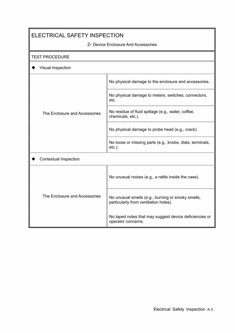
Electrical Safety Inspection A-3
ELECTRICAL SAFETY INSPECTION 2- Device Enclosure And Accessories
TEST PROCEDURE
Visual Inspection
The Enclosure and Accessories
No physical damage to the enclosure and accessories.
No physical damage to meters, switches, connectors, etc.
No residue of fluid spillage (e.g., water, coffee, chemicals, etc.).
No physical damage to probe head (e.g., crack)
No loose or missing parts (e.g., knobs, dials, terminals, etc.).
Contextual Inspection
The Enclosure and Accessories
No unusual noises (e.g., a rattle inside the case).
No unusual smells (e.g., burning or smoky smells, particularly from ventilation holes).
No taped notes that may suggest device deficiencies or operator concerns.
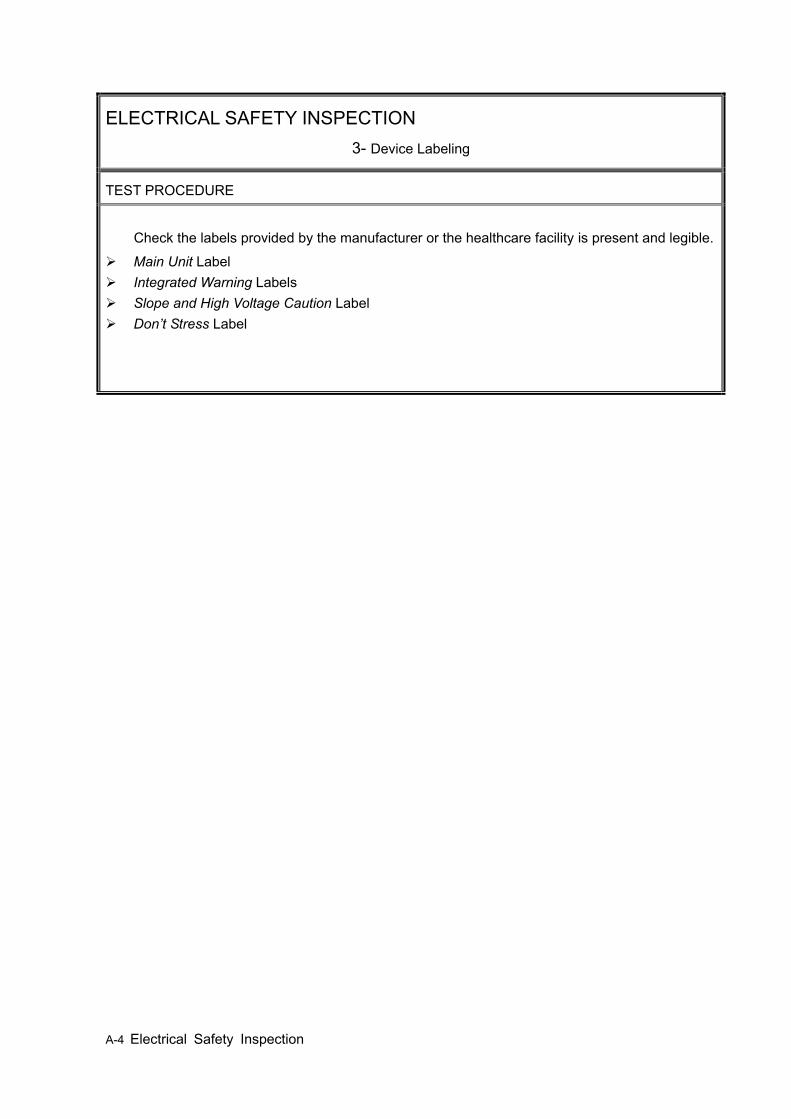
A-4 Electrical Safety Inspection
ELECTRICAL SAFETY INSPECTION 3- Device Labeling
TEST PROCEDURE
Check the labels provided by the manufacturer or the healthcare facility is present and legible.
Main Unit Label Integrated Warning Labels Slope and High Voltage Caution Label Don’t Stress Label
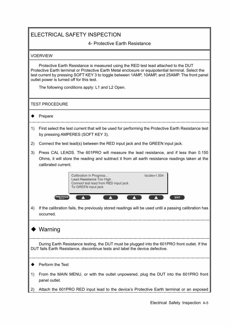
Electrical Safety Inspection A-5
ELECTRICAL SAFETY INSPECTION 4- Protective Earth Resistance
VOERVIEW
Protective Earth Resistance is measured using the RED test lead attached to the DUT Protective Earth terminal or Protective Earth Metal enclosure or equipotential terminal. Select the test current by pressing SOFT KEY 3 to toggle between 1AMP, 10AMP, and 25AMP. The front panel outlet power is turned off for this test.
The following conditions apply: L1 and L2 Open.
TEST PROCEDURE
Prepare
1) First select the test current that will be used for performing the Protective Earth Resistance test by pressing AMPERES (SOFT KEY 3).
2) Connect the test lead(s) between the RED input jack and the GREEN input jack.
3) Press CAL LEADS. The 601PRO will measure the lead resistance, and if less than 0.150 Ohms, it will store the reading and subtract it from all earth resistance readings taken at the calibrated current.
4) If the calibration fails, the previously stored readings will be used until a passing calibration has occurred.
Warning
During Earth Resistance testing, the DUT must be plugged into the 601PRO front outlet. If the DUT fails Earth Resistance, discontinue tests and label the device defective.
Perform the Test
1) From the MAIN MENU, or with the outlet unpowered, plug the DUT into the 601PRO front panel outlet.
2) Attach the 601PRO RED input lead to the device’s Protective Earth terminal or an exposed
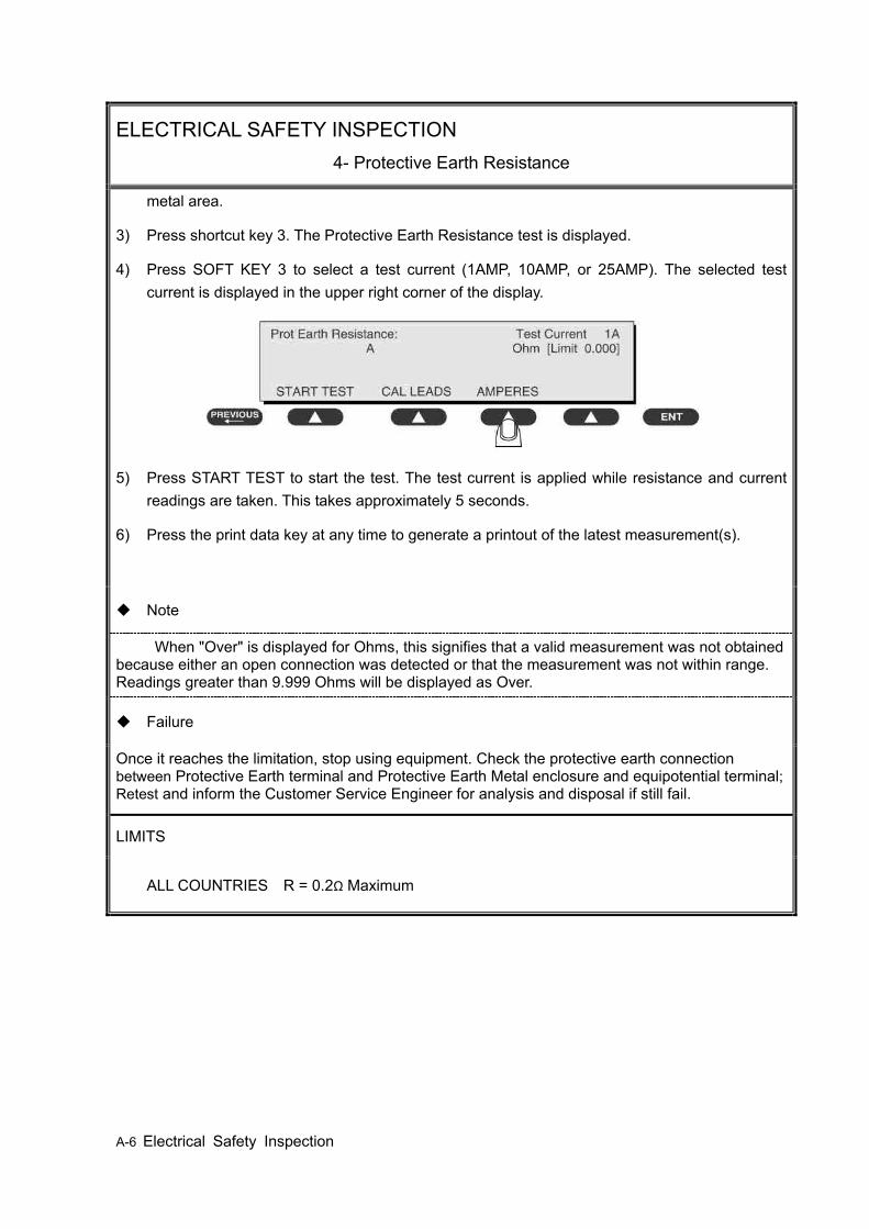
A-6 Electrical Safety Inspection
ELECTRICAL SAFETY INSPECTION 4- Protective Earth Resistance
metal area.
3) Press shortcut key 3. The Protective Earth Resistance test is displayed.
4) Press SOFT KEY 3 to select a test current (1AMP, 10AMP, or 25AMP). The selected test current is displayed in the upper right corner of the display.
5) Press START TEST to start the test. The test current is applied while resistance and current readings are taken. This takes approximately 5 seconds.
6) Press the print data key at any time to generate a printout of the latest measurement(s).
Note
When "Over" is displayed for Ohms, this signifies that a valid measurement was not obtained because either an open connection was detected or that the measurement was not within range. Readings greater than 9.999 Ohms will be displayed as Over.
Failure
Once it reaches the limitation, stop using equipment. Check the protective earth connection between Protective Earth terminal and Protective Earth Metal enclosure and equipotential terminal; Retest and inform the Customer Service Engineer for analysis and disposal if still fail.
LIMITS
ALL COUNTRIES R = 0.2Ω Maximum
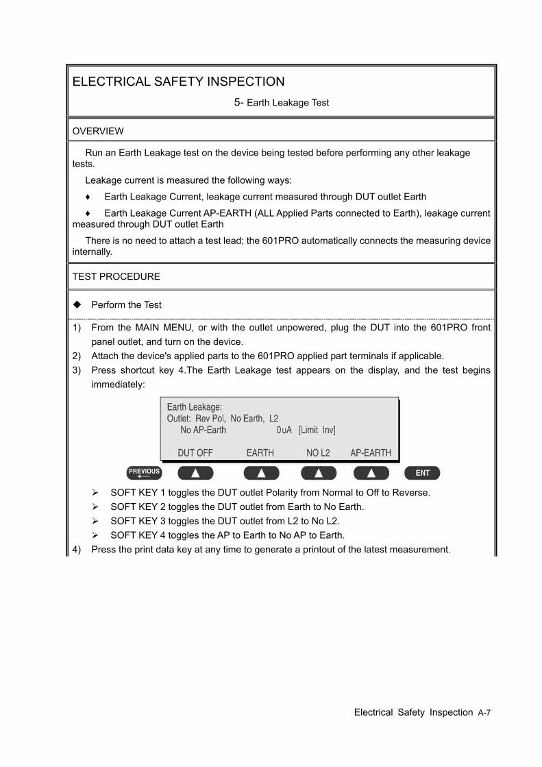
Electrical Safety Inspection A-7
ELECTRICAL SAFETY INSPECTION 5- Earth Leakage Test
OVERVIEW
Run an Earth Leakage test on the device being tested before performing any other leakage tests.
Leakage current is measured the following ways:
♦ Earth Leakage Current, leakage current measured through DUT outlet Earth
♦ Earth Leakage Current AP-EARTH (ALL Applied Parts connected to Earth), leakage current measured through DUT outlet Earth
There is no need to attach a test lead; the 601PRO automatically connects the measuring device internally.
TEST PROCEDURE
Perform the Test
1) From the MAIN MENU, or with the outlet unpowered, plug the DUT into the 601PRO front panel outlet, and turn on the device.
2) Attach the device's applied parts to the 601PRO applied part terminals if applicable. 3) Press shortcut key 4.The Earth Leakage test appears on the display, and the test begins
immediately:
SOFT KEY 1 toggles the DUT outlet Polarity from Normal to Off to Reverse. SOFT KEY 2 toggles the DUT outlet from Earth to No Earth. SOFT KEY 3 toggles the DUT outlet from L2 to No L2. SOFT KEY 4 toggles the AP to Earth to No AP to Earth.
4) Press the print data key at any time to generate a printout of the latest measurement.
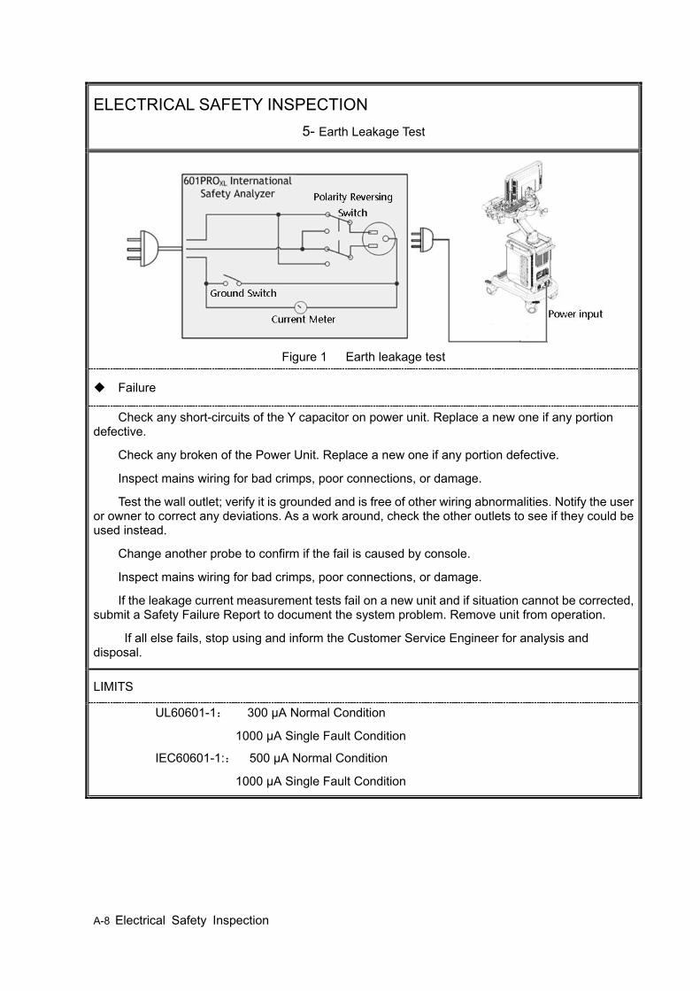
A-8 Electrical Safety Inspection
ELECTRICAL SAFETY INSPECTION 5- Earth Leakage Test
Figure 1 Earth leakage test
Failure
Check any short-circuits of the Y capacitor on power unit. Replace a new one if any portion defective.
Check any broken of the Power Unit. Replace a new one if any portion defective.
Inspect mains wiring for bad crimps, poor connections, or damage.
Test the wall outlet; verify it is grounded and is free of other wiring abnormalities. Notify the user or owner to correct any deviations. As a work around, check the other outlets to see if they could be used instead.
Change another probe to confirm if the fail is caused by console.
Inspect mains wiring for bad crimps, poor connections, or damage.
If the leakage current measurement tests fail on a new unit and if situation cannot be corrected, submit a Safety Failure Report to document the system problem. Remove unit from operation.
If all else fails, stop using and inform the Customer Service Engineer for analysis and disposal.
LIMITS
UL60601-1: 300 μA Normal Condition
1000 μA Single Fault Condition
IEC60601-1:: 500 μA Normal Condition
1000 μA Single Fault Condition
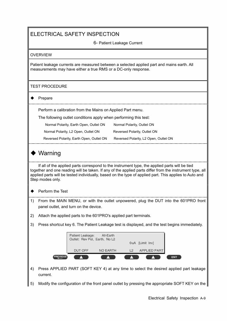
Electrical Safety Inspection A-9
ELECTRICAL SAFETY INSPECTION 6- Patient Leakage Current
OVERVIEW
Patient leakage currents are measured between a selected applied part and mains earth. All measurements may have either a true RMS or a DC-only response.
TEST PROCEDURE
Prepare
Perform a calibration from the Mains on Applied Part menu.
The following outlet conditions apply when performing this test:
Normal Polarity, Earth Open, Outlet ON Normal Polarity, Outlet ON
Normal Polarity, L2 Open, Outlet ON Reversed Polarity, Outlet ON
Reversed Polarity, Earth Open, Outlet ON Reversed Polarity, L2 Open, Outlet ON
Warning
If all of the applied parts correspond to the instrument type, the applied parts will be tied together and one reading will be taken. If any of the applied parts differ from the instrument type, all applied parts will be tested individually, based on the type of applied part. This applies to Auto and Step modes only.
Perform the Test
1) From the MAIN MENU, or with the outlet unpowered, plug the DUT into the 601PRO front panel outlet, and turn on the device.
2) Attach the applied parts to the 601PRO's applied part terminals.
3) Press shortcut key 6. The Patient Leakage test is displayed, and the test begins immediately.
4) Press APPLIED PART (SOFT KEY 4) at any time to select the desired applied part leakage current.
5) Modify the configuration of the front panel outlet by pressing the appropriate SOFT KEY on the
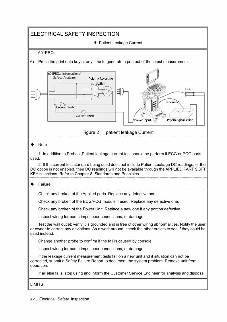
A-10 Electrical Safety Inspection
ELECTRICAL SAFETY INSPECTION 6- Patient Leakage Current
601PRO.
6) Press the print data key at any time to generate a printout of the latest measurement.
Figure 2 patient leakage Current
Note
1, In addition to Probes ,Patient leakage current test should be perform if ECG or PCG parts used;
2, If the current test standard being used does not include Patient Leakage DC readings, or the DC option is not enabled, then DC readings will not be available through the APPLIED PART SOFT KEY selections. Refer to Chapter 8, Standards and Principles.
Failure
Check any broken of the Applied parts. Replace any defective one.
Check any broken of the ECG/PCG module if used, Replace any defective one.
Check any broken of the Power Unit. Replace a new one if any portion defective.
Inspect wiring for bad crimps, poor connections, or damage.
Test the wall outlet; verify it is grounded and is free of other wiring abnormalities. Notify the user or owner to correct any deviations. As a work around, check the other outlets to see if they could be used instead.
Change another probe to confirm if the fail is caused by console.
Inspect wiring for bad crimps, poor connections, or damage.
If the leakage current measurement tests fail on a new unit and if situation can not be corrected, submit a Safety Failure Report to document the system problem. Remove unit from operation.
If all else fails, stop using and inform the Customer Service Engineer for analysis and disposal.
LIMITS
Electrical Safety Inspection A-11
ELECTRICAL SAFETY INSPECTION 6- Patient Leakage Current
All countries
For BF ECG input and transducer
100μA Normal Condition
500μA Single Fault Condition
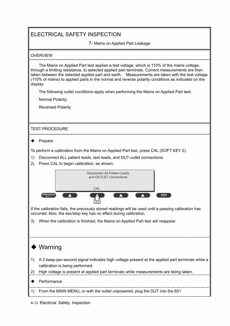
A-12 Electrical Safety Inspection
ELECTRICAL SAFETY INSPECTION 7- Mains on Applied Part Leakage
OVERVIEW
The Mains on Applied Part test applies a test voltage, which is 110% of the mains voltage, through a limiting resistance, to selected applied part terminals. Current measurements are then taken between the selected applied part and earth. Measurements are taken with the test voltage (110% of mains) to applied parts in the normal and reverse polarity conditions as indicated on the display.
The following outlet conditions apply when performing the Mains on Applied Part test.
Normal Polarity;
Reversed Polarity
TEST PROCEDURE
Prepare
To perform a calibration from the Mains on Applied Part test, press CAL (SOFT KEY 2).
1) Disconnect ALL patient leads, test leads, and DUT outlet connections. 2) Press CAL to begin calibration, as shown:
If the calibration fails, the previously stored readings will be used until a passing calibration has occurred. Also, the esc/stop key has no effect during calibration.
3) When the calibration is finished, the Mains on Applied Part test will reappear.
Warning
1) A 2-beep-per-second signal indicates high voltage present at the applied part terminals while a calibration is being performed.
2) High voltage is present at applied part terminals while measurements are being taken.
Performance
1) From the MAIN MENU, or with the outlet unpowered, plug the DUT into the 601
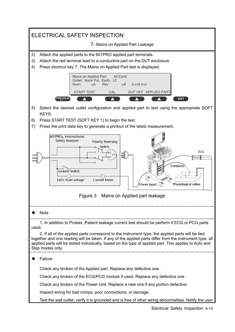
Electrical Safety Inspection A-13
ELECTRICAL SAFETY INSPECTION 7- Mains on Applied Part Leakage
2) Attach the applied parts to the 601PRO applied part terminals. 3) Attach the red terminal lead to a conductive part on the DUT enclosure. 4) Press shortcut key 7. The Mains on Applied Part test is displayed.
5) Select the desired outlet configuration and applied part to test using the appropriate SOFT
KEYS: 6) Press START TEST (SOFT KEY 1) to begin the test. 7) Press the print data key to generate a printout of the latest measurement.
Figure 3 Mains on Applied part leakage
Note
1, In addition to Probes ,Patient leakage current test should be perform if ECG or PCG parts used;
2, If all of the applied parts correspond to the instrument type, the applied parts will be tied together and one reading will be taken. If any of the applied parts differ from the instrument type, all applied parts will be tested individually, based on the type of applied part. This applies to Auto and Step modes only.
Failure
Check any broken of the Applied part. Replace any defective one.
Check any broken of the ECG/PCG module if used, Replace any defective one.
Check any broken of the Power Unit. Replace a new one if any portion defective.
Inspect wiring for bad crimps, poor connections, or damage.
Test the wall outlet; verify it is grounded and is free of other wiring abnormalities. Notify the user
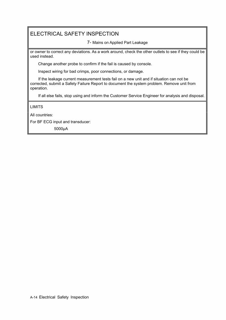
A-14 Electrical Safety Inspection
ELECTRICAL SAFETY INSPECTION 7- Mains on Applied Part Leakage
or owner to correct any deviations. As a work around, check the other outlets to see if they could be used instead.
Change another probe to confirm if the fail is caused by console.
Inspect wiring for bad crimps, poor connections, or damage.
If the leakage current measurement tests fail on a new unit and if situation can not be corrected, submit a Safety Failure Report to document the system problem. Remove unit from operation.
If all else fails, stop using and inform the Customer Service Engineer for analysis and disposal.
LIMITS
All countries:
For BF ECG input and transducer:
5000μA
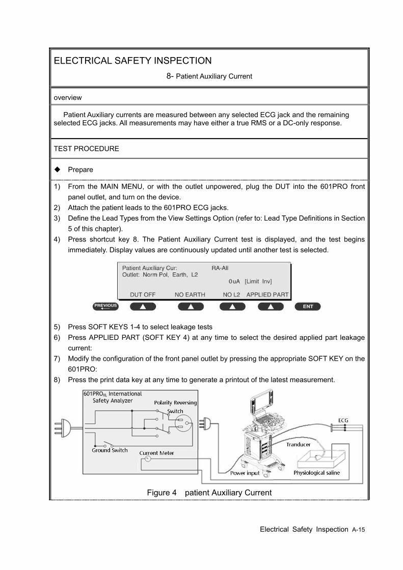
Electrical Safety Inspection A-15
ELECTRICAL SAFETY INSPECTION 8- Patient Auxiliary Current
overview
Patient Auxiliary currents are measured between any selected ECG jack and the remaining selected ECG jacks. All measurements may have either a true RMS or a DC-only response.
TEST PROCEDURE
Prepare
1) From the MAIN MENU, or with the outlet unpowered, plug the DUT into the 601PRO front panel outlet, and turn on the device.
2) Attach the patient leads to the 601PRO ECG jacks. 3) Define the Lead Types from the View Settings Option (refer to: Lead Type Definitions in Section
5 of this chapter). 4) Press shortcut key 8. The Patient Auxiliary Current test is displayed, and the test begins
immediately. Display values are continuously updated until another test is selected.
5) Press SOFT KEYS 1-4 to select leakage tests 6) Press APPLIED PART (SOFT KEY 4) at any time to select the desired applied part leakage
current: 7) Modify the configuration of the front panel outlet by pressing the appropriate SOFT KEY on the
601PRO: 8) Press the print data key at any time to generate a printout of the latest measurement.
Figure 4 patient Auxiliary Current
A-16 Electrical Safety Inspection
ELECTRICAL SAFETY INSPECTION 8- Patient Auxiliary Current
Note
If the current test standard being used does not include Patient Auxiliary Current DC readings, or the DC option is not enabled, then DC readings will not be available through the APPLIED PART SOFT KEY selections.
Failure
Check any broken of the AC cable. Replace a new one if any portion defective.
Check any broken of the enclosure. Replace any defective part.
Inspect wiring for bad crimps, poor connections, or damage.
Test the wall outlet; verify it is grounded and is free of other wiring abnormalities. Notify the user or owner to correct any deviations. As a work around, check the other outlets to see if they could be used instead.
Change another probe to confirm if the fail is caused by console.
Inspect wiring for bad crimps, poor connections, or damage.
If the leakage current measurement tests fail on a new unit and if situation can not be corrected, submit a Safety Failure Report to document the system problem. Remove unit from operation.
If all else fails, stop using and inform the Customer Service Engineer for analysis and disposal.
LIMITS
All countries
For BF ECG input and transducer
100μA Normal Condition
500μA Single Fault Condition

Electrical Safety Inspection A-A-1
ELECTRICAL SAFETY INSPECTION FORM
(Class I equipment) Overall assessment:
□ Scheduled inspection Test item: 1, 2, 3
□ Unopened repair type Test item: 1, 2, 3
□ Opened repair type, not modify the power part
including transformer or patient circuit board
Test item: 1, 2, 3, 4, 5
□ Opened repair type, modify the power part
including transformer or patient circuit board
Test item: 1, 2, 3, 4, 5, 6, 7, 8
Location: Technician:
Equipment: Control Number:
Manufacturer: Model: SN:
Measurement equipment /SN: Date of Calibration:
Inspection and Testing Pass/Fail Limit
1 Power Cord Plug
2 Device Enclosure and Accessories
3 Device Labeling
4 Protective Earth Resistance Ω Max 0.2 Ω
5 Earth
Leakage
Normal condition(NC)
____μA
Max:
NC: 300μA(refer to
UL60601-1) *
NC: 500μA(refer to
IEC60601-1) *
SFC: 1000μA Single Fault condition(SFC)
____μA
6
Patient
Leakage
Current
Normal condition(NC) □BF____μA Max:
BF applied part:
NC:100μA, SFC: 500μA Single Fault condition(SFC) □BF____μA
7 Mains on Applied Part Leakage □BF____μA Max:
BF applied part: 5000μA
8 Patient Auxliary
Leakage Current
Normal condition(NC) □BF____μA
Max:
BF applied part:
NC:100μA, SFC: 500μA Single Fault
condition(SFC) □BF____μA
Note: The equipment which sell to America shall comply with the requirement of UL60601-1,
others shall comply with the requirement of IEC60601-1. Name/ Signature: ____________________ Date:_____________________________


Phantom Usage Illustration B-1
Appendix B Phantom Usage Illustration
Targets Disposal of Phantom KS107BD A1——A5: Axial resolution target group B: Blind-area target group
C: Longitudinal target group D: Horizontal target group
E: Mimic tumor F: Mimic sac (diam 10mm) and stone G Mimic sac (diam 6mm) 4. Line Target System There are 8 groups of nylon line targets disposed as shown in the figure. 1.A1——A5: Axial and lateral resolution target group. The distances between the horizontal branch and the acoustic window are 30, 50, 70, 120 and 160mm, the center horizontal distances between two adjacent lines of A1 and A2 groups are 1, 5, 4, 3, 2mm, A3~A5 groups are 5, 4, 3, 2mm. The center longitudinal distances between two adjacent lines of the longitudinal branches are 4, 3, 2, 1mm. 2.B: Blind-area target group. Center horizontal distance of adjacent lines is 10mm, distances to the acoustic window are 10, 9, 8, 7, 6, 5, 4, 3mm. 3.C: Longitudinal target group. 19 target lines with a 10mm center distance between adjacent lines. 4.D:
Horizontal target group. 7 target lines with a 20mm center distance between adjacent lines.

B-2 Phantom Usage Illustration
Targets disposal- KS107BD A1——A4 Axial resolution target group
B1——B4 Lateral resolution target group
C Longitudinal target group
D Horizontal target group
E1——E3 Mimic sacs with diameters of 2, 4, 6mm
4. Line Target System There are 8 groups of line targets disposed in TM material as shown in the figure. 1.A1——A4: Axial resolution target group. The upmost lines in each target locate at the depth of 10, 30, 50, 70mm, the center longitudinal distances of each group (from the top down) are 3, 2, 1, 0.5mm, and the horizontal distance is 1mm. 2.B1——B4: Lateral resolution target group. Locate at a depth of 10, 30, 50, 70mm, with a center horizontal distance of 4, 3, 2, 1mm in each group. 3.C: Longitudinal target group. 12 target lines with a 10mm center distance between adjacent lines. 4.D: Horizontal target group. Locate at a depth of 40mm, with a 20mm center distance between adjacent lines.
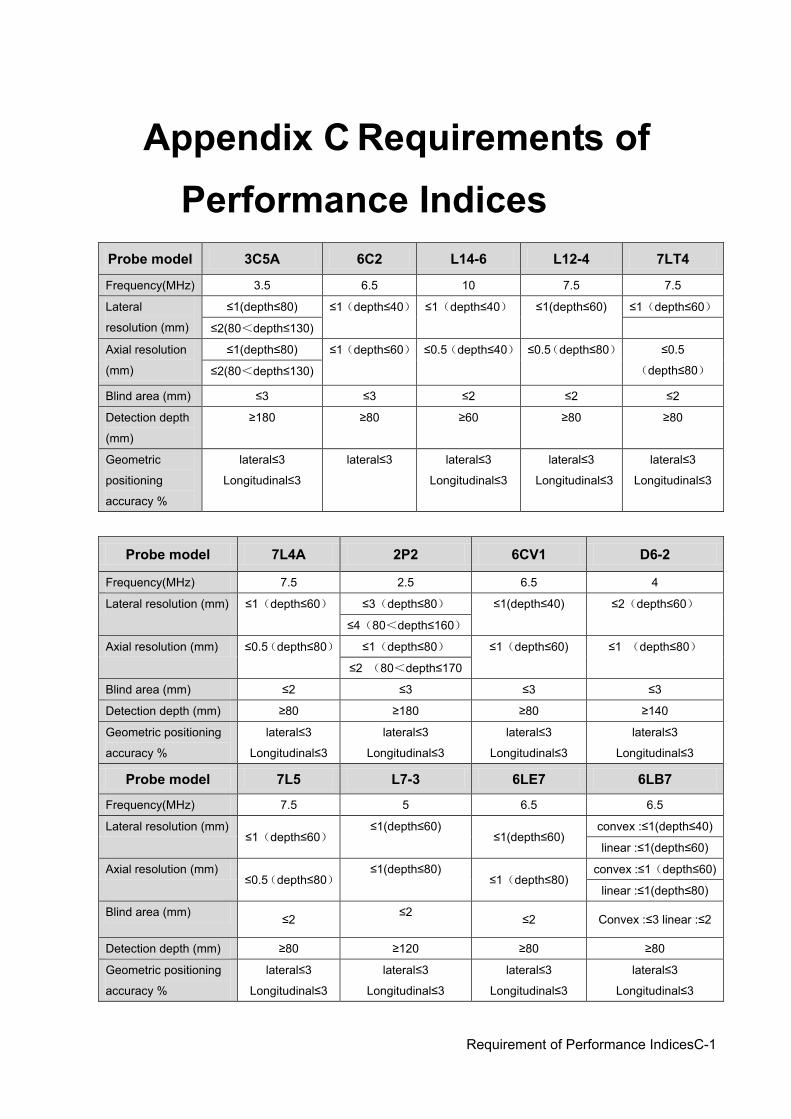
Requirement of Performance IndicesC-1
Appendix C Requirements of Performance Indices
Probe model 3C5A 6C2 L14-6 L12-4 7LT4
Frequency(MHz) 3.5 6.5 10 7.5 7.5
Lateral
resolution (mm)
≤1(depth≤80) ≤1(depth≤40) ≤1(depth≤40) ≤1(depth≤60) ≤1(depth≤60)
≤2(80<depth≤130)
Axial resolution
(mm)
≤1(depth≤80) ≤1(depth≤60) ≤0.5(depth≤40) ≤0.5(depth≤80) ≤0.5
(depth≤80) ≤2(80<depth≤130)
Blind area (mm) ≤3 ≤3 ≤2 ≤2 ≤2
Detection depth
(mm)
≥180 ≥80 ≥60 ≥80 ≥80
Geometric
positioning
accuracy %
lateral≤3
Longitudinal≤3
lateral≤3
lateral≤3
Longitudinal≤3
lateral≤3
Longitudinal≤3
lateral≤3
Longitudinal≤3
Probe model 7L4A 2P2 6CV1 D6-2
Frequency(MHz) 7.5 2.5 6.5 4
Lateral resolution (mm) ≤1(depth≤60) ≤3(depth≤80) ≤1(depth≤40) ≤2(depth≤60)
≤4(80<depth≤160)
Axial resolution (mm) ≤0.5(depth≤80) ≤1(depth≤80) ≤1(depth≤60) ≤1 (depth≤80)
≤2 (80<depth≤170
Blind area (mm) ≤2 ≤3 ≤3 ≤3
Detection depth (mm) ≥80 ≥180 ≥80 ≥140
Geometric positioning
accuracy %
lateral≤3
Longitudinal≤3
lateral≤3
Longitudinal≤3
lateral≤3
Longitudinal≤3
lateral≤3
Longitudinal≤3
Probe model 7L5 L7-3 6LE7 6LB7
Frequency(MHz) 7.5 5 6.5 6.5
Lateral resolution (mm) ≤1(depth≤60)
≤1(depth≤60) ≤1(depth≤60)
convex :≤1(depth≤40)
linear :≤1(depth≤60)
Axial resolution (mm) ≤0.5(depth≤80)
≤1(depth≤80) ≤1(depth≤80)
convex :≤1(depth≤60)
linear :≤1(depth≤80)
Blind area (mm) ≤2 ≤2 ≤2 Convex :≤3 linear :≤2
Detection depth (mm) ≥80 ≥120 ≥80 ≥80
Geometric positioning
accuracy %
lateral≤3
Longitudinal≤3
lateral≤3
Longitudinal≤3
lateral≤3
Longitudinal≤3
lateral≤3
Longitudinal≤3


P/N: 046-003597-00 (V14.0)