development of wireless rtd temperature measurement using ...
24
i DEVELOPMENT OF WIRELESS RTD TEMPERATURE MEASUREMENT USING DECADE BOX OLIVEA KAREN AK BUHAN This thesis is submitted as partial fulfillment of the requirements for the award of the Bachelor of Electrical Engineering (Hons.) (Electronics) Faculty of Electrical & Electronics Engineering Universiti Malaysia Pahang NOVEMBER 2010
-
Upload
hoangduong -
Category
Documents
-
view
225 -
download
6
Transcript of development of wireless rtd temperature measurement using ...

i
DEVELOPMENT OF WIRELESS RTD TEMPERATURE
MEASUREMENT USING DECADE BOX
OLIVEA KAREN AK BUHAN
This thesis is submitted as partial fulfillment of the
requirements for the award of the
Bachelor of Electrical Engineering (Hons.) (Electronics)
Faculty of Electrical & Electronics Engineering
Universiti Malaysia Pahang
NOVEMBER 2010
ii
“I hereby acknowledge that the scope and quality of this thesis is qualified for the award of
the Bachelor Degree of Electrical Engineering (Electronics)”
Signature : ______________________________________________
Name : NAJIDAH HAMBALI
Date : 29 NOVEMBER 2010
iii
“All the trademark and copyrights use herein are property of their respective owner.
References of information from other sources are quoted accordingly; otherwise the
information presented in this report is solely work of the author.”
Signature : ____________________________
Author : OLIVEA KAREN AK BUHAN
Date : 29 NOVEMBER 2010
v
ACKNOWLEDGEMENTS
I am grateful and would like to express my sincere gratitude to my supervisor
Miss Najidah Hambali, for her germinal ideas, invaluable guidance, continuous
encouragement, motivation, advice and constant support in making this research
possible.
Besides, I also would like to express very special thanks to my co-supervisor
Mr. Zamri, Mr.shahrizal and other lectures for their suggestions and co-operation
throughout the project.
Many special thanks go to my friends for their excellent co-operation,
inspirations and supports during this project. And I also thanks for their brilliant idea
and my classmate whom involve directly or indirectly in this project.
Finally, I acknowledge my sincere indebtedness and gratitude to my parents
for their love, dream amd sacrifice throughtout my life. Thanks for their
encouragement and support.
Thank You.
vi
ABSTRACT
The project proposed is to develop GUI (Graphical User Interface)
application using visual basic. Wireless system is interfacing between camputer-
based and instrument for temperature measurement to measure temperature where
the data from measurement process can be directly use for other purpose, such as
calculation and data monitoring. This project will involve designing the GUI
application to monitor temperature changes using visual basic 2008. Manual method
in temperature measurement are measure and calculate the data manually. The
system is developed to facilitate for taking the data directly from the computer. This
project will use the wireless RTD system as a sensor to interface between computer
and temperature instrument such as temperature transmitter. Wireless RTD system
that will use is called Zig-bee technology. Zig-bee technology are self configuring
short range network and low cost. Decade box will use as a testing and calibration to
create a resistance or capacitance with a specific value by using a combination of the
rotary decade switches. For this project, the expected outcome is GUI application
will monitor temperature changes through Zigbee wireless system. This project will
make the wireless process instrumentation and wireless terminal technology for
instrumentation directly leads to efficient process and equipment validation in
current technology.
vii
ABSTRAK
Projek yang dicadangkan adalah untuk membangunkan GUI (Graphical User
Interface) aplikasi yang menggunakan Visual Basis. Sistem komunikasi tanpa wayar
antara komputer dan instrumen bagi pengukuran suhu untuk mengukur suhu di mana
data dari proses pengukuran dapat terus digunakan untuk tujuan lain, seperti
pengiraan dan data pemantauan. Projek ini akan melibatkan merancang aplikasi GUI
untuk memantau perubahan suhu menggunakan Visual Basic 2008. Kaedah manual
dalam pengukuran suhu mengukur dan menghitung data secara manual. Sistem ini
dibangunkan untuk memudahkan untuk mengambil data secara terus dari
komputer. Projek ini akan menggunakan sistem tanpa wayar RTD sebagai pengesan
untuk perhubungan komunikasi antara komputer dan alat pemancar suhu seperti
suhu. Sistem tanpa wayar RTD yang akan menggunakan teknologi yang dikenali
sebagai Zigbee. Teknologi Zigbee ini adalah untuk menyediakan rangkaian jarak
pendek dan kos yang rendah. Decade Box akan digunakan sebagai ujian dan kalibrasi
untuk mencipta rintangan atau kapasitor dengan nilai tertentu dengan menggunakan
kombinasi dari suis dekad pemutaran. Untuk projek ini, hasil yang dijangkakan
adalah aplikasi GUI akan memantau perubahan suhu melalui sistem tanpa wayar
Zigbee. Projek ini akan memastikan instrumentasi proses tanpa wayar, dan teknologi
terminal tanpa wayar untuk instrumentasi secara langsung ke arah proses yang
cekap dan validasi peralatan teknologi yang terkini.
viii
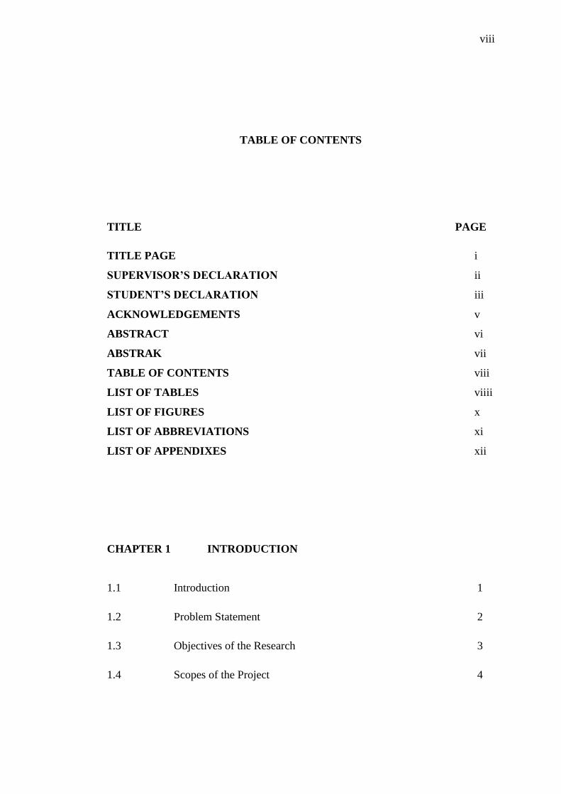
TABLE OF CONTENTS
TITLE PAGE
TITLE PAGE i
SUPERVISOR’S DECLARATION ii
STUDENT’S DECLARATION iii
ACKNOWLEDGEMENTS v
ABSTRACT vi
ABSTRAK vii
TABLE OF CONTENTS viii
LIST OF TABLES viiii
LIST OF FIGURES x
LIST OF ABBREVIATIONS xi
LIST OF APPENDIXES xii
CHAPTER 1 INTRODUCTION
1.1 Introduction 1
1.2 Problem Statement 2
1.3 Objectives of the Research 3
1.4 Scopes of the Project 4
ix
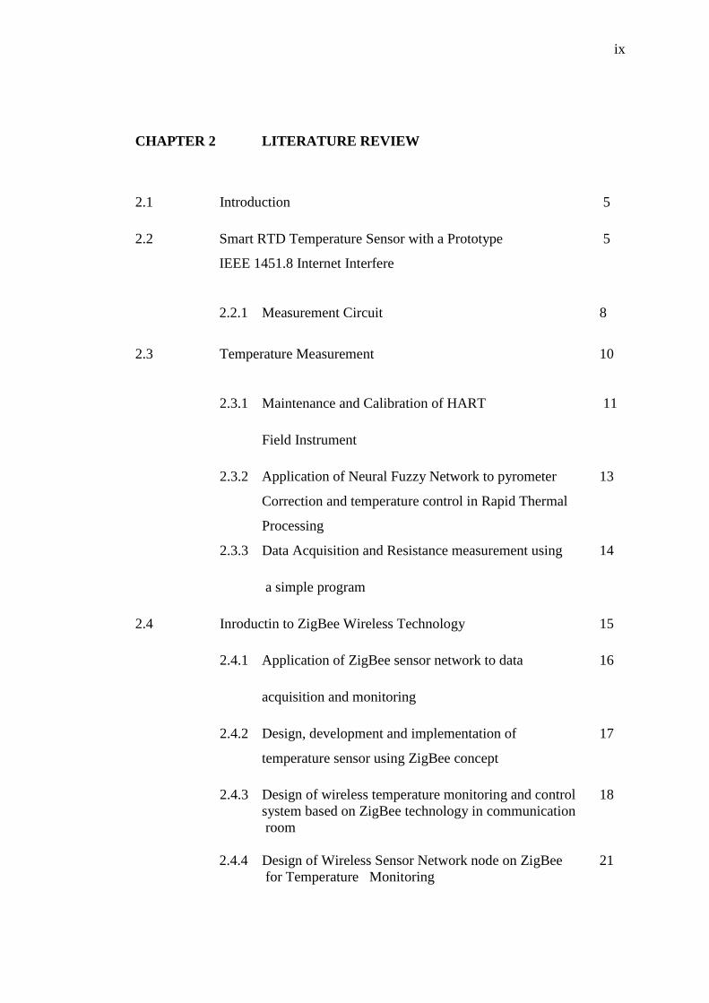
CHAPTER 2 LITERATURE REVIEW
2.1 Introduction 5
2.2 Smart RTD Temperature Sensor with a Prototype 5
IEEE 1451.8 Internet Interfere
2.2.1 Measurement Circuit 8
2.3 Temperature Measurement 10
2.3.1 Maintenance and Calibration of HART 11
Field Instrument
2.3.2 Application of Neural Fuzzy Network to pyrometer 13
Correction and temperature control in Rapid Thermal
Processing
2.3.3 Data Acquisition and Resistance measurement using 14
a simple program
2.4 Inroductin to ZigBee Wireless Technology 15
2.4.1 Application of ZigBee sensor network to data 16
acquisition and monitoring
2.4.2 Design, development and implementation of 17
temperature sensor using ZigBee concept
2.4.3 Design of wireless temperature monitoring and control 18
system based on ZigBee technology in communication
room
2.4.4 Design of Wireless Sensor Network node on ZigBee 21
for Temperature Monitoring

x
2.5 Introduction to Visual Basic 2008 Edition 22
CHAPTER 3 METHODOLOGY
3.1 Introduction 24
3.1.1 Overview 25
3.2 Instrument
3.2.1 Basic Instrument Connection 26
3.2.2 YOKOGAWA Temperature Transmitter 27
3.2.3 HART Communicator 29
3.2.4 Decade Box 30
3.3 Hardware
3.3.1 Introsuction to ZIGBEE 31
3.5.2 Feature Overviews 32
3.4 Software
3.4.1 Visual Basic Edition 2008 34
3.4.2 SQL Server Express 36
3.4.3 X-CTU configuration and Utility Test 38-43
3.5 Work of Flow Chart 44
xi
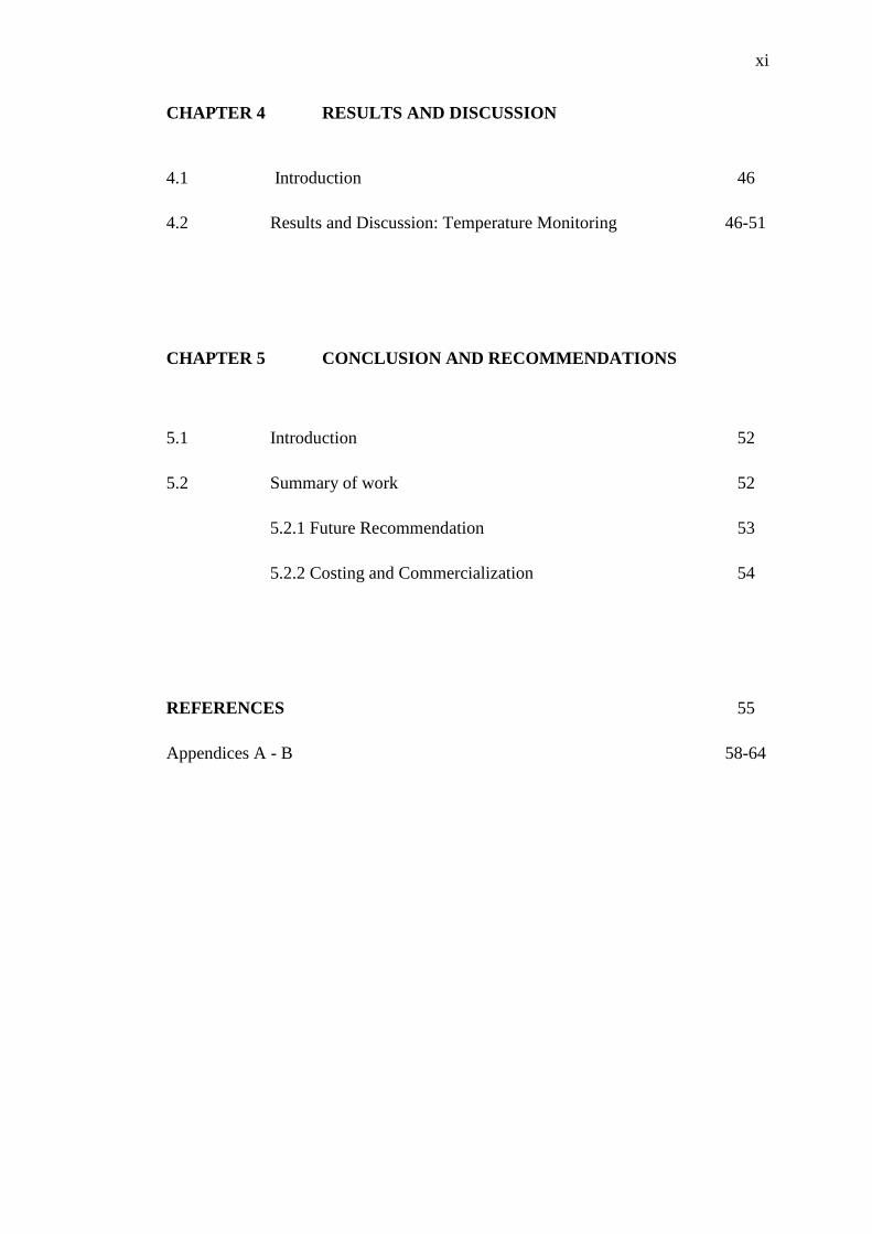
CHAPTER 4 RESULTS AND DISCUSSION
4.1 Introduction 46
4.2 Results and Discussion: Temperature Monitoring 46-51
CHAPTER 5 CONCLUSION AND RECOMMENDATIONS
5.1 Introduction 52
5.2 Summary of work 52
5.2.1 Future Recommendation 53
5.2.2 Costing and Commercialization 54
REFERENCES 55
Appendices A - B 58-64
xii
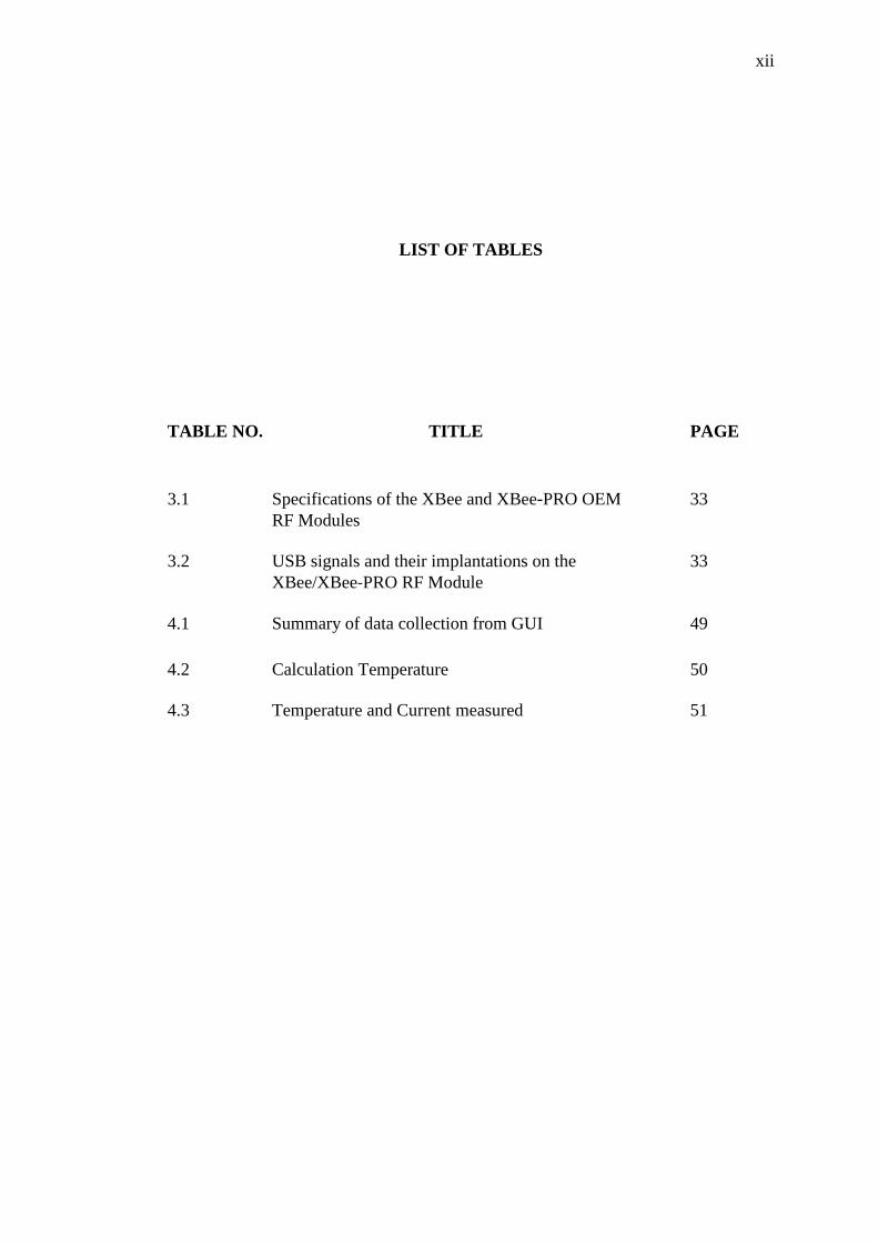
LIST OF TABLES
TABLE NO. TITLE PAGE
3.1 Specifications of the XBee and XBee‐PRO OEM 33
RF Modules
3.2 USB signals and their implantations on the 33
XBee/XBee‐PRO RF Module
4.1 Summary of data collection from GUI 49
4.2 Calculation Temperature 50
4.3 Temperature and Current measured 51
xiii
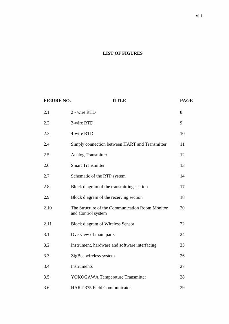
LIST OF FIGURES
FIGURE NO. TITLE PAGE
2.1 2 - wire RTD 8
2.2 3-wire RTD 9
2.3 4-wire RTD 10
2.4 Simply connection between HART and Transmitter 11
2.5 Analog Transmitter 12
2.6 Smart Transmitter 13
2.7 Schematic of the RTP system 14
2.8 Block diagram of the transmitting section 17
2.9 Block diagram of the receiving section 18
2.10 The Structure of the Communication Room Monitor 20
and Control system
2.11 Block diagram of Wireless Sensor 22
3.1 Overview of main parts 24
3.2 Instrument, hardware and software interfacing 25
3.3 ZigBee wireless system 26
3.4 Instruments 27
3.5 YOKOGAWA Temperature Transmitter 28
3.6 HART 375 Field Communicator 29

xiv
3.7 Model 2793 Decade box 30
3.8 ZIGBEE Chip 31
3.9 Zigbee-PRO with USB Developmet Board 32
3.10 Create New Project 35
3.11 New Project dialog box 35
3.12 Toolbox Window 36
3.13 SQL Manager 2008 for SQL Server 37
3.14 X-CTU window 39
3.15 COM Test/Query Modem response 40
3.16 Range Test Tab 41
3.17 Terminal Tab 42
3.18 Assemble packet window 42
3.19 Modem configuration tab 43
3.20 Work of Flow Chart 44
4.1 Design for Monitor function of GUI 43
4.2 Design For Data Record Of GUI 46
4.3 GUI displays the data after run the system 47
4.4 Data Record of GUI application 48
4.5 Graph of Relatioship between Temperature and 49
Resistance

xv
LIST OF ABBREVIATIONS
ADC Analog- Digital Converter
DC Direct Current
GUI Graphical User Interface
GPIB General-Purpose Interface Bus
IDE Integarted Developement Environment
LCD Liquid Crystal Display
LRV Lower Range Value
PWM Pulse Width Modulate
RTD Resistance Temperature Detector
URV Upper Range Value
VB Visual Basic
xvi
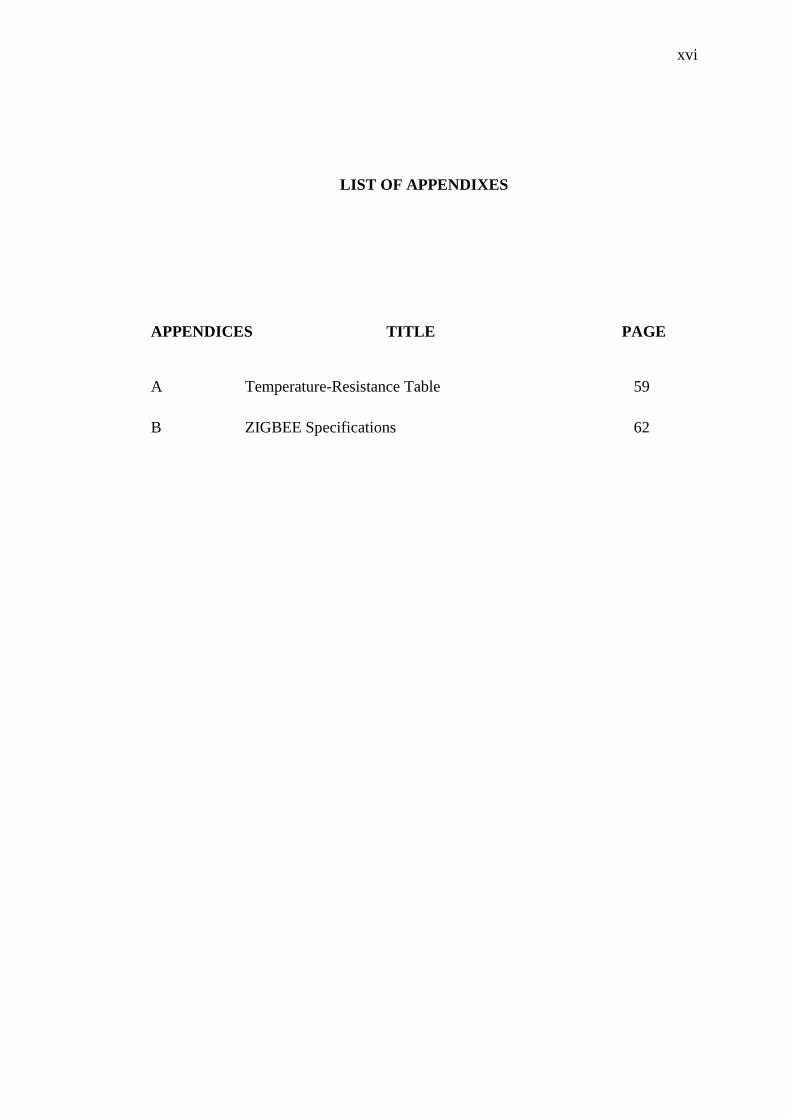
LIST OF APPENDIXES
APPENDICES TITLE PAGE
A Temperature-Resistance Table 59
B ZIGBEE Specifications 62
1
CHAPTER 1
INTRODUCTION
1.1 INTRODUCTION
In the industrial, temperature is one of the most frequently measured parameters
in process system. The electrical thermometer is used, to sense and control the process
temperatures. Regular calibration of these thermometers is critical to ensure consistent
quality of product manufactured, as well as providing regulatory compliance for some
industries. Industrial process temperature measurements are more critical than ever.
Attempts to improve the quality or efficiency of industrial processes has led to a rapid
increase in the number of temperature sensors installed in these systems as well as
increased requirements for temperature measurement. The project is generally based on
using temperature sensor devices for collecting and monitoring data from the plant
station and transferring the measured temperature parameters to the computer.
2
In this project, GUI (Graphical User Interface) application will be developed
using visual basic. This software is developed and responsible for establishing and
manages communications between PC and wireless system. The wireless system is used
to interface between instrument and computer. From this project, Decade Box represents
RTD (Resistance Temperature Detector) is use as a temperature sensor to detect
temperature change. The input will convert into current signal between 4 – 20 mA.
1.2 PROBLEM STATEMENT
In the industrial, temperature measurement is one of the most frequently
measured parameters in process system. Resistance Temperature detectors have become
industry standards for simple and cost-effective temperature measurement. However,
achieving such measurement in an accurate, reliable and cost-effective manner is a
challenging problem. If station is far away from the workplace, it is difficult to collect
and monitor temperature changes. It wastes time to take and check temperature reading
at plant station. They also need to analysis and monitor the data everyday or weekly to
make sure the instrument in good condition.
3
1.3 OBJECTIVE OF THE RESEARCH
The objectives of the project are:
1. To develop GUI (Graphical User Interface) application using visual
basic.
Visual Basic is use as a main programming language. Data will transfer
to PC and data will display in GUI application.
2. To interface between instrument and software application using the
wireless system.
Zig-Bee Wireless system is use to interface between instrument and
computer. This system will use PIC controller as a converter that is
convert analog signal from temperature transmitter to digital signal
before data is transmit.
3. To monitor the temperature measurement directly by software
application.
Temperature measurement is the way that can be used to measure
temperature where data from measurement process can be directly use for
other purpose, such as analysis and monitoring data.
4
1.4 SCOPE OF THE PROJECT
The scopes of this project are:
1. Develop GUI (Graphical User Interface) application using Visual Basic
in software application.
Easy to collect and monitor the data from temperature transmitter by
developed GUI application and programming using Visual Basic 2008
Edition software.
2. Zig-bee wireless technology will use to interface between computer and
temperature instrument such as temperature transmitter, HART
communicator, etc.
In industry plant, wireless technology can help user and ease for user to
collect data and doing observation of temperature only in controller
room. So, user do not need to go the plant station and take readings
manually.
3. Decade Box represents the RTD (Resistance Temperature Detector) is
use as input device to detect temperature changes.
This device is suitable for precision measurement applications and the
calibration of laboratory or workplace equipment.
5
CHAPTER 2
LITERATURE REVIEW
2.1 Introduction
This chapter will explain about the literature review part that taking from
journals or articles which related with the project.
2.2 Smart RTD Temperature sensor with a prototype IEEE 1451.8 Internet
Interfere
This research was conducted by Darold Wobschall and Wai sing Poh from
Department of Electrical Engineering, University at Buffalo, Amherst. The Resistance
Temperature Detector (RTD) was a sensor which can benefit greatly by smart transducer
techniques that was, digital signal processing and digital transmission of data. The RTD
was a stable sensor capable of resolving temperature changes to at least 0.001 °C over a
temperature range of -200 °C to 400 °C continuously and over 600 °C for shorter times.
6
Thus, the readout must been capable of about 2 pm resolution while most analog
readouts, such as the 4-20 mA ament loop, are have errors in the range of 100 to 500
ppm A microcomputer with a built-in high-resolution analog-todigital converter (ADC)
is used here to acquire the signal [1].
Research by three partners from delphi corporation, Resistive Temperature
device (RTD) high temperature sensor was developed for exhaust gas temperature
measurement. Extensive modeling and optimization was used to supplement testing in
development. The sensor was developed to be capable of withstanding harsh
environments (-40 to 1000 degrees Celcius), typical of engine applications, including
poisons, while maintaining high accuracy (< 0.5% drift after 500 hrs of aging at 950
degree Celcius) [2].
Resistance Temperature Detector (RTD) is basically a temperature sensitive
resistor. It is a positive temperature coefficient device, which means that the resistance
increases with temperature. The resistance of the metal is increasing with temperature.
The resistive property of the metal is called its resistivity. The resistive property defines
length and cross sectional area required to fabricate an RTD of a given value. The
resistance is proportional to length and inversely proportional to the cross sectional area
that see in the Equation (2.1):
R= (r X L)/A (2.1)
Where R = Resistance (ohms)
r = Resistivity (ohms)
L = Length
A = Cross sectional area
The devices criterion for selecting a material to make an RTD is that the material
must be malleable so that it can be formed into small wires. It must have a repeatable
and stable slope or curve. The material should also be a resistant to corrosion and low
cost. It is preferred that the material have a linear resistance verses temperature slope.
7
Some of the common RTD materials are Platinum with a temperature coefficient
of 0.00385 - 0.003923 Ω/Ω/°C and practical temperature range of -452 to +1100°F (-
269 to +593°C). The platinum RTD has the best accuracy and stability among the
common RTD materials. The resistance versus temperature curve is fairly linear and the
temperature range is the widest of the common RTD materials. Platinum has a very high
resistivity, which means that only a small quantity of platinum is required to fabricate a
sensor and making platinum cost competitive with other RTD materials. Platinum is the
only RTD commonly available with a thin film element style. As a Primary uses,
Platinum is the primary choice for most industrial, commercial, laboratory and other
critical RTD temperature measurements. Copper, nickel and nickel iron are also
commonly used RTD materials. Platinum RTDs are manufactured with two distinct
types or temperature coefficients (µ). The temperature coefficient (µ) is the slope of the
platinum RTD between 0°C to 100°C [3].
This is calculated by the following formula in the Equation (2.2):
µ = (R100 - R0)/ (100 X R0) (2.2)
Where µ= Temperature Coefficient (W/W/°C)
R100 = RTD resistance at 100°C
R0 = RTD resistance at 0°C
8
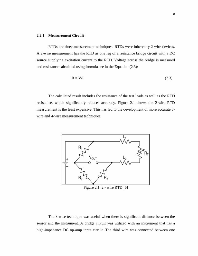
2.2.1 Measurement Circuit
RTDs are three measurement techniques. RTDs were inherently 2-wire devices.
A 2-wire measurement has the RTD as one leg of a resistance bridge circuit with a DC
source supplying excitation current to the RTD. Voltage across the bridge is measured
and resistance calculated using formula see in the Equation (2.3):
R = V/I (2.3)
The calculated result includes the resistance of the test leads as well as the RTD
resistance, which significantly reduces accuracy. Figure 2.1 shows the 2-wire RTD
measurement is the least expensive. This has led to the development of more accurate 3-
wire and 4-wire measurement techniques.
Figure 2.1: 2 - wire RTD [5]
The 3-wire technique was useful when there is significant distance between the
sensor and the instrument. A bridge circuit was utilized with an instrument that has a
high-impedance DC op-amp input circuit. The third wire was connected between one
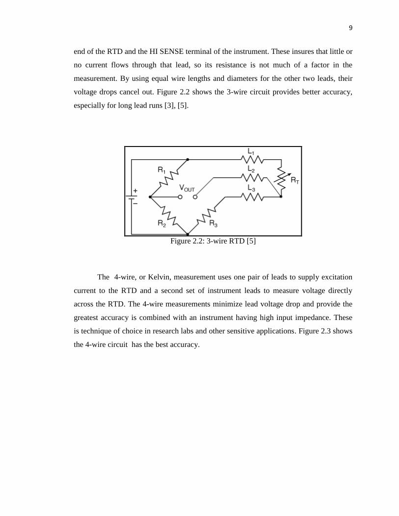
9
end of the RTD and the HI SENSE terminal of the instrument. These insures that little or
no current flows through that lead, so its resistance is not much of a factor in the
measurement. By using equal wire lengths and diameters for the other two leads, their
voltage drops cancel out. Figure 2.2 shows the 3-wire circuit provides better accuracy,
especially for long lead runs [3], [5].
Figure 2.2: 3-wire RTD [5]
The 4-wire, or Kelvin, measurement uses one pair of leads to supply excitation
current to the RTD and a second set of instrument leads to measure voltage directly
across the RTD. The 4-wire measurements minimize lead voltage drop and provide the
greatest accuracy is combined with an instrument having high input impedance. These
is technique of choice in research labs and other sensitive applications. Figure 2.3 shows
the 4-wire circuit has the best accuracy.