
Development of Large-Sized Mobile Harbor Crane · Features of the MHI large-sized mobile harbor...
4
Mitsubishi Heavy Industries, Ltd. Technical Review Vol.40 Extra No.2 (Jan. 2003) 1 Development of Large-Sized Mobile Harbor Crane With the recent trend toward containerization, it has become necessary for local small and medium-sized harbors to use mobile harbor cranes that are capable of handling containers as well as other general cargoes in different styles. Hence, demands for large-sized mobile harbor cranes, which are self-traveling and versatile but do not require any additional civil works to increase the bearing strength of foundation soil, are increasing. Mitsubishi Heavy Industries, Ltd. (MHI), using its latest crane technology, has recently developed a mobile harbor crane that is differentiated from other commercially available models in its easy-to-operate characteristics: (1) crane operation without interference with on-deck 13 rows by 5 stacks containers loaded on Panamax size containerships, (2) capable of handling 40.6 ton containers, (3) interlocking dual-axis anti-sway function and (4) oblique traveling by independent steering mechanism. 1. Introduction 1. Introduction 1. Introduction 1. Introduction 1. Introduction A general outline of the mobile harbor crane is as follows. It consists of a traveling device with rubber-tired wheels for traveling freely on harbor areas, outrigger and a crane unit to load and unload cargo onto or from a ship. The trav- eling device of the crane consists mainly of a frame for traveling, an outrigger device, a steering device and an operator's cab. Rubber-tired wheels are used when the crane travels, and an outrigger is used to support the crane unit during cargo handling operations. The crane unit con- sists of a slewing device to swing around the crane unit, a luffing device to raise the jib and a hoisting device to lift cargo. Cargo handling operation is performed by the three different actions of the crane: slewing, luffing and hoisting. In addition, various types of cargo such as containers, general cargo, lumber and bulk cargo can be handled by changing the lifting tools. A mobile harbor crane, when compared to a gantry crane fixed on rails installed on the wharf, is a low-cost, light- weight facility that does not require large-scale civil works for reinforcement of foundation or installation of other wharf equipment such as rails and power supply unit, re- ducing the initial equipment investment. Also, in handling of cargo, it can be used to rearrange stacks of cargo on the wharf yard as well as loading or unloading them on or from a ship. Thus, a mobile harbor crane has the feature of ver- satility and accordingly can be used to handle cargo in various ways. 2. Main specifications 2. Main specifications 2. Main specifications 2. Main specifications 2. Main specifications Table 1 able 1 able 1 able 1 able 1 shows the main specifications of the MHI mo- bile harbor crane. It is designed to handle containers loaded on a 40 000 DWT Panamax size containership and hoist 40.6- ton containers. The crane also has a sufficient slewing radius for use as backup of a container crane. To increase the cargo handling efficiency, the operating speed of each action is higher than that of conventional rubber-tired cranes. The crane is equipped with both swivel hook and expandable spreader as hoisting tools to meet the require- ment for most handling needs of containers. 3. Features of the MHI large-sized mobile harbor crane 3. Features of the MHI large-sized mobile harbor crane 3. Features of the MHI large-sized mobile harbor crane 3. Features of the MHI large-sized mobile harbor crane 3. Features of the MHI large-sized mobile harbor crane Mobile harbor cranes used in small and medium-sized Noriaki Miyata Toshihito Shimotsu Nobuhito Iwamoto Masaki Nishioka Wataru Mizunuma Table 1 Main specifications Applicable containership class (DWT) 40 000 On-deck container stacks 13 rows by 5 stacks Rated hoisting capacity (t) 65, max. Applicable container (t) 40.6 Slewing radius (m) 53 Lift: above GL (m) 35 Lift: below GL (m) -12 Hoisting speed (m/min) 0 to 72 Luffing speed (m/min) Avg. 60 Slewing speed (rpm) 1.2, max. Traveling speed (m/min) 67 Outrigger span (m) 13.0 Outrigger spacing (m) 13.5 Outrigger load (t) 220 Maximum load on wheels (t) 19
Transcript of Development of Large-Sized Mobile Harbor Crane · Features of the MHI large-sized mobile harbor...

Mitsubishi Heavy Industries, Ltd.Technical Review Vol.40 Extra No.2 (Jan. 2003)
1
Development of Large-SizedMobile Harbor Crane
With the recent trend toward containerization, it has become necessary for local small and medium-sized harbors touse mobile harbor cranes that are capable of handling containers as well as other general cargoes in different styles.Hence, demands for large-sized mobile harbor cranes, which are self-traveling and versatile but do not require anyadditional civil works to increase the bearing strength of foundation soil, are increasing. Mitsubishi Heavy Industries,Ltd. (MHI), using its latest crane technology, has recently developed a mobile harbor crane that is differentiated fromother commercially available models in its easy-to-operate characteristics: (1) crane operation without interferencewith on-deck 13 rows by 5 stacks containers loaded on Panamax size containerships, (2) capable of handling 40.6 toncontainers, (3) interlocking dual-axis anti-sway function and (4) oblique traveling by independent steering mechanism.
1. Introduction1. Introduction1. Introduction1. Introduction1. IntroductionA general outline of the mobile harbor crane is as follows.It consists of a traveling device with rubber-tired wheels
for traveling freely on harbor areas, outrigger and a craneunit to load and unload cargo onto or from a ship. The trav-eling device of the crane consists mainly of a frame fortraveling, an outrigger device, a steering device and anoperator's cab. Rubber-tired wheels are used when thecrane travels, and an outrigger is used to support the craneunit during cargo handling operations. The crane unit con-sists of a slewing device to swing around the crane unit, aluffing device to raise the jib and a hoisting device to liftcargo. Cargo handling operation is performed by the threedifferent actions of the crane: slewing, luffing and hoisting.
In addition, various types of cargo such as containers,general cargo, lumber and bulk cargo can be handled bychanging the lifting tools.
A mobile harbor crane, when compared to a gantry cranefixed on rails installed on the wharf, is a low-cost, light-weight facility that does not require large-scale civil worksfor reinforcement of foundation or installation of otherwharf equipment such as rails and power supply unit, re-ducing the initial equipment investment. Also, in handlingof cargo, it can be used to rearrange stacks of cargo on thewharf yard as well as loading or unloading them on or froma ship. Thus, a mobile harbor crane has the feature of ver-satility and accordingly can be used to handle cargo invarious ways.
2. Main specifications2. Main specifications2. Main specifications2. Main specifications2. Main specificationsTTTTTable 1able 1able 1able 1able 1 shows the main specifications of the MHI mo-
bile harbor crane.It is designed to handle containers loaded on a
40 000 DWT Panamax size containership and hoist 40.6-ton containers. The crane also has a sufficient slewingradius for use as backup of a container crane. To increasethe cargo handling efficiency, the operating speed of eachaction is higher than that of conventional rubber-tiredcranes. The crane is equipped with both swivel hook andexpandable spreader as hoisting tools to meet the require-ment for most handling needs of containers.
3. Features of the MHI large-sized mobile harbor crane3. Features of the MHI large-sized mobile harbor crane3. Features of the MHI large-sized mobile harbor crane3. Features of the MHI large-sized mobile harbor crane3. Features of the MHI large-sized mobile harbor craneMobile harbor cranes used in small and medium-sized
Noriaki Miyata
Toshihito Shimotsu
Nobuhito Iwamoto
Masaki Nishioka
Wataru Mizunuma
Table 1 Main specifications
Applicable containership class (DWT) 40 000
On-deck container stacks 13 rows by 5 stacks
Rated hoisting capacity (t) 65, max.
Applicable container (t) 40.6
Slewing radius (m) 53
Lift: above GL (m) 35
Lift: below GL (m) -12
Hoisting speed (m/min) 0 to 72
Luffing speed (m/min) Avg. 60
Slewing speed (rpm) 1.2, max.
Traveling speed (m/min) 67
Outrigger span (m) 13.0
Outrigger spacing (m) 13.5
Outrigger load (t) 220
Maximum load on wheels (t) 19
Mitsubishi Heavy Industries, Ltd.Technical Review Vol.40 Extra No.2 (Jan. 2003)
2
harbors are, in many cases, required to have a performancecomparable to that of gantry cranes in cargo handling ca-pability and maneuverability.
The crane introduced in this paper has the features de-scribed below to meet these requirements:(1) This crane is designed so that its boom does not inter-
fere with the top edge of the stack of containers when itis operated to handle on-deck 13 rows by 5 stacks con-tainers on Panamax size containerships, while theconventional cranes need to be operated while takingcare not to touch the on-deck cargo.
(2) It can hoist heavy-weight containers (40.6 tons), whichare now increasing by replacing ordinary 30.5-ton con-tainers.
(3) It is equipped with interlocking dual-axis anti-sway func-tion that relieves crane operator from sway control andimproves maneuverability and cargo handling efficiency.
(4) It is equipped with independent steering mechanismand oblique traveling function to improve maneuver-ability and efficiency in bringing the crane alongsidecontainerships, in addition to the conventional curvetraveling function.
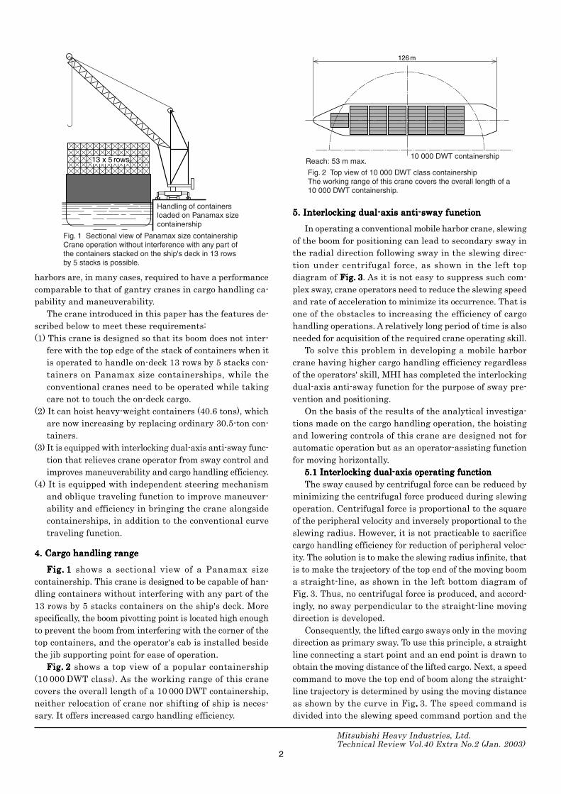
4. Cargo handling range4. Cargo handling range4. Cargo handling range4. Cargo handling range4. Cargo handling rangeFigFigFigFigFig..... 11111 shows a sectional view of a Panamax size
containership. This crane is designed to be capable of han-dling containers without interfering with any part of the13 rows by 5 stacks containers on the ship's deck. Morespecifically, the boom pivotting point is located high enoughto prevent the boom from interfering with the corner of thetop containers, and the operator's cab is installed besidethe jib supporting point for ease of operation.
FigFigFigFigFig..... 22222 shows a top view of a popular containership(10 000 DWT class). As the working range of this cranecovers the overall length of a 10 000 DWT containership,neither relocation of crane nor shifting of ship is neces-sary. It offers increased cargo handling efficiency.
5. Interlocking dual-axis anti-sway function5. Interlocking dual-axis anti-sway function5. Interlocking dual-axis anti-sway function5. Interlocking dual-axis anti-sway function5. Interlocking dual-axis anti-sway functionIn operating a conventional mobile harbor crane, slewing
of the boom for positioning can lead to secondary sway inthe radial direction following sway in the slewing direc-tion under centrifugal force, as shown in the left topdiagram of FigFigFigFigFig..... 33333. As it is not easy to suppress such com-plex sway, crane operators need to reduce the slewing speedand rate of acceleration to minimize its occurrence. That isone of the obstacles to increasing the efficiency of cargohandling operations. A relatively long period of time is alsoneeded for acquisition of the required crane operating skill.
To solve this problem in developing a mobile harborcrane having higher cargo handling efficiency regardlessof the operators' skill, MHI has completed the interlockingdual-axis anti-sway function for the purpose of sway pre-vention and positioning.
On the basis of the results of the analytical investiga-tions made on the cargo handling operation, the hoistingand lowering controls of this crane are designed not forautomatic operation but as an operator-assisting functionfor moving horizontally.
5.1 Interlocking dual-axis operating function5.1 Interlocking dual-axis operating function5.1 Interlocking dual-axis operating function5.1 Interlocking dual-axis operating function5.1 Interlocking dual-axis operating functionThe sway caused by centrifugal force can be reduced by
minimizing the centrifugal force produced during slewingoperation. Centrifugal force is proportional to the squareof the peripheral velocity and inversely proportional to theslewing radius. However, it is not practicable to sacrificecargo handling efficiency for reduction of peripheral veloc-ity. The solution is to make the slewing radius infinite, thatis to make the trajectory of the top end of the moving booma straight-line, as shown in the left bottom diagram ofFig. 3. Thus, no centrifugal force is produced, and accord-ingly, no sway perpendicular to the straight-line movingdirection is developed.
Consequently, the lifted cargo sways only in the movingdirection as primary sway. To use this principle, a straightline connecting a start point and an end point is drawn toobtain the moving distance of the lifted cargo. Next, a speedcommand to move the top end of boom along the straight-line trajectory is determined by using the moving distanceas shown by the curve in Fig..... 3. The speed command isdivided into the slewing speed command portion and the
126 m
Fig. 2 Top view of 10 000 DWT class containershipThe working range of this crane covers the overall length of a 10 000 DWT containership.
Reach: 53 m max.10 000 DWT containership13 x 5 rows
Fig. 1 Sectional view of Panamax size containershipCrane operation without interference with any part of the containers stacked on the ship's deck in 13 rows by 5 stacks is possible.
Handling of containers loaded on Panamax size containership

Mitsubishi Heavy Industries, Ltd.Technical Review Vol.40 Extra No.2 (Jan. 2003)
3
luffing speed command portion. These two different com-mands are jointly applied to the boom operation so thatthe top end of the boom moves along a straight-line trajec-tory for slewing and luffing.
5.2 Anti-sway control function5.2 Anti-sway control function5.2 Anti-sway control function5.2 Anti-sway control function5.2 Anti-sway control functionPrimary sway still occurs in the direction of straight-
line movement during the interlocking dual-axis operation.To suppress the primary sway, a field-proven feedforwardanti-sway system is employed. In addition, the mobile har-bor crane has a real-time speed compensation function thatmaintains the anti-sway effect regardless of the length of
the hanging wire rope, because the wire rope length changeswith luffing operation being performed by the level luffingfunction, and also because the hoisting operation is car-ried out manually by the operator.
5.3 Touch panel control5.3 Touch panel control5.3 Touch panel control5.3 Touch panel control5.3 Touch panel controlThe interlocking dual-axis anti-sway operation of the
mobile harbor crane can be easily controlled on the touchpanel screen shown in FigFigFigFigFig..... 44444 and with the switches on theoperation console.
Firstly, coordinate presetting is made on the touch panelscreen to determine the position of the containership rela-
Fig. 4 Touch panel screen Easy input through touch panel screen is possible.
Operating instructions given through this panel
Coordinate presetting Land-side container grounding direction
1.5
1.0
0.5
0 5 10 15 20 25 30 35 40 45 50
0
-2
6
4
2
50 10 15 20 25 30 35 40 45 50
1
0
-1
-2 50 10 15 20 25 30 35 40 45 50
m / s
deg / s
deg / s(s)
(s)
(s)
Fig. 3 Interlocking dual-axis anti-sway functionSway is suppressed by jointly controlling slewing and luffing operations.
Boom
Boom
End point
End point
Secondary sway occurs.
Peripheral sway
Radial sway
Start point
Start point
Slewing operation
Only primary sway occurs.
Sway in straight-line moving direction
Interlocking dual-axis straight-line operation
Boom top-end moving speed (straight-line moving direction)
Stop point
Dividing into slewing and luffing speeds
Slewing speed
Luffing speed

Mitsubishi Heavy Industries, Ltd.Technical Review Vol.40 Extra No.2 (Jan. 2003)
4
tive to the crane. For coordinate presetting, two arbitrarycontainers are selected from the array of containers on theship displayed on the touch panel screen, the spreader isbrought to the actual position of the first selected containerby manual operation, and the preset key is depressed. Whenthe same procedure is repeated for another container, thecoordinate presetting is completed. The actual operationcommand is given to a target container by simply desig-nating it on the screen. After the target container has beenlifted to a safe level in the air by manual hoisting opera-tion, the joint operation start command is given. Theinterlocking dual-axis anti-sway function then starts work-ing automatically and the positioning of the container tothe designated position is started. Even if the length of thewire rope varies with the intervention of manual hoisting atthis stage, the anti-sway control function remains valid withthe support of the real-time speed compensation function.
In addition, when the lifted container is being un-loaded on the wharf, it is possible to give an instructionto ground it parallel to or perpendicular to the wharf.Also, the lifted container can be automatically turnedaround in the air by swivelling the hook so that all thecontainers are unloaded in the same direction. In thisway, the mobile harbor crane can be used for variouscargo handling operation.
6. Traveling function6. Traveling function6. Traveling function6. Traveling function6. Traveling functionThe hydraulically operated traveling device consists of
an outrigger unit, a steering unit and a common hydraulicunit for compact design.
The steering unit is provided with an independent hy-draulic steering mechanism and feedback control to satisfyvarious traveling conditions. As shown in FigFigFigFigFig..... 55555, whenrounding a curve in the usual manner, the rear wheels aresteered in the opposite direction to the front wheels to makethe turning radius smaller. When adjusting the crane tothe position of a ship or in a similar steering operation, thefront and rear wheels can be steered in the same directionto perform oblique traveling for ease of position adjustmentor to bring the crane closer to the ship.
Furthermore, each axle is synchronously controlled inorder to minimize tire wear and axle load.
7. Conclusion7. Conclusion7. Conclusion7. Conclusion7. ConclusionMHI has developed a large-sized mobile harbor crane
suitable for use in small and medium-sized harbors. De-mand for the crane is expected to increase further becauseof the following features:(1) Crane structure allowing container handling operation
without interference with on-deck 13 rows by 5 stackscontainers on Panamax size containerships,
(2) Capable of handling a 40.6 ton containers, which arebecoming increasingly popular in the industry,
(3) Interlocking dual-axis anti-sway function that improvesmaneuverability of crane and cargo handling efficiency,and
(4) Independent steering and oblique traveling mechanismthat improves maneuverability of the crane for position-ing close to a ship.From now on, MHI will explore the possibilities of fur-
ther improvement of functions through verification testsand cargo handling operations, using the mobile harborcrane in actual operations for improvement of its maneu-verability and cargo handling efficiency.
Hiroshima Machinery Works
Hiroshima Research &Development Center,Technical Headquarters
General Machinery &Special VehicleHeadquarters
Noriaki Miyata Toshihito Shimotsu Nobuhito Iwamoto
Masaki Nishioka Wataru Mizunuma
Fig. 5 Steering function for travelingIndependent hydraulic steering mechanism is adopted for moving through curves and oblique traveling function.
Containership
Moving through curves traveling Oblique traveling


![MOBILE HARBOUR CRANE SPREADERS - Bromma€¦ · mobile harbor crane spreaders includes single-lift options such as the EH5U spreader [capable of handling 20’ or 40’ containers];](https://static.fdocuments.net/doc/165x107/604b5b3a9388356f1e7baec6/mobile-harbour-crane-spreaders-bromma-mobile-harbor-crane-spreaders-includes-single-lift.jpg)


