
Conceptual and basic designs of the Mobile Harbor crane ...
11
Struct Multidisc Optim (2014) 50:505–515 DOI 10.1007/s00158-014-1073-3 INDUSTRIAL APPLICATION Conceptual and basic designs of the Mobile Harbor crane based on topology and shape optimization In Gwun Jang · Kyung-Soo Kim · Byung Man Kwak Received: 7 August 2013 / Revised: 21 January 2014 / Accepted: 14 February 2014 / Published online: 30 March 2014 © Springer-Verlag Berlin Heidelberg 2014 Abstract The Mobile Harbor (MH) has been recently pro- posed as a novel maritime cargo transfer system that can move to a container ship anchored in the deep sea and handle containers directly at sea with the aid of a stabi- lized MH crane. Because this system operates under at-sea conditions, the MH crane must be designed to support an inertia load and wind force, as well as its self-weight. The wave-induced motions of the MH, e.g. rolling, pitching, and heaving, generate a significant amount of inertia load, which has not been considered in the design of conventional quayside cranes installed on stable ground. Wind force is also a critical design factor due to the higher wind velocity in the open sea. In addition to the aforementioned struc- tural rigidity, mass minimization is also important in the structural design of MH cranes because it reduces the over- turning moment and therefore enhances ship stability. In this paper, the sensitivities of the design-dependent loads (i.e. self-weight, inertia load, and wind force) are derived with respect to the design variables, and then a topology optimization is conducted with the derived sensitivities in I. G. Jang () The Cho Chun Shik Graduate School for Green Transportation, Korea Advanced Institute of Science and Technology, 373-1 Guseong-dong, Yuseong-gu, Daejeon 305-701, Republic of Korea e-mail: [email protected] K.-S. Kim · B. M. Kwak Department of Mechanical Engineering, Korea Advanced Institute of Science and Technology, 373-1 Guseong-dong, Yuseong-gu, Daejeon 305-701, Republic of Korea K.-S. Kim e-mail: [email protected] B. M. Kwak e-mail: [email protected] order to obtain a conceptual design. Then, the conceptual design is elaborated into a three-dimensional basic design through shape optimization with design regulations for off- shore cranes. Through the integrated design process with the topology and shape optimizations, a conceptual and basic design is successfully obtained for the MH crane. Keywords Topology optimization · Shape optimization · Design-dependent load · Mobile Harbor · Offshore crane 1 Introduction Because container shipping is important in worldwide trade, the quantity of goods transported by container ships increases every year. This has led to rapid increases in the size of container ships from 5,000 twenty-foot equivalent units (TEU) to over 10,000 TEU in order to achieve more efficient maritime logistics. The advent of such supersized container ships has prompted the need for enhanced capac- ity and capability at container ports because the existing ports have already reached their limitation in terms of facil- ities and drafts. Therefore, there is an urgent need for new port systems (or transfer systems) to be developed in order to effectively manage mega-sized container ships. In order to meet these societal and logistic demands, the concept of the Mobile Harbor (MH) (Kim et al. 2013, 2014) was recently proposed to directly load and unload containers from container ships anchored in the open sea, as shown in Fig. 1. The significant technical challenge in developing the MH is to consider the environmental disturbances, such as waves and wind, under the operating conditions and survival conditions in both structural design and control.
Transcript of Conceptual and basic designs of the Mobile Harbor crane ...

Struct Multidisc Optim (2014) 50:505–515DOI 10.1007/s00158-014-1073-3
INDUSTRIAL APPLICATION
Conceptual and basic designs of the Mobile Harbor cranebased on topology and shape optimization
In Gwun Jang · Kyung-Soo Kim · Byung Man Kwak
Received: 7 August 2013 / Revised: 21 January 2014 / Accepted: 14 February 2014 / Published online: 30 March 2014© Springer-Verlag Berlin Heidelberg 2014
Abstract The Mobile Harbor (MH) has been recently pro-posed as a novel maritime cargo transfer system that canmove to a container ship anchored in the deep sea andhandle containers directly at sea with the aid of a stabi-lized MH crane. Because this system operates under at-seaconditions, the MH crane must be designed to support aninertia load and wind force, as well as its self-weight. Thewave-induced motions of the MH, e.g. rolling, pitching,and heaving, generate a significant amount of inertia load,which has not been considered in the design of conventionalquayside cranes installed on stable ground. Wind force isalso a critical design factor due to the higher wind velocityin the open sea. In addition to the aforementioned struc-tural rigidity, mass minimization is also important in thestructural design of MH cranes because it reduces the over-turning moment and therefore enhances ship stability. Inthis paper, the sensitivities of the design-dependent loads(i.e. self-weight, inertia load, and wind force) are derivedwith respect to the design variables, and then a topologyoptimization is conducted with the derived sensitivities in
I. G. Jang (�)The Cho Chun Shik Graduate School for Green Transportation,Korea Advanced Institute of Science and Technology, 373-1Guseong-dong, Yuseong-gu, Daejeon 305-701, Republic of Koreae-mail: [email protected]
K.-S. Kim · B. M. KwakDepartment of Mechanical Engineering, Korea Advanced Instituteof Science and Technology, 373-1 Guseong-dong, Yuseong-gu,Daejeon 305-701, Republic of Korea
K.-S. Kime-mail: [email protected]
B. M. Kwake-mail: [email protected]
order to obtain a conceptual design. Then, the conceptualdesign is elaborated into a three-dimensional basic designthrough shape optimization with design regulations for off-shore cranes. Through the integrated design process with thetopology and shape optimizations, a conceptual and basicdesign is successfully obtained for the MH crane.
Keywords Topology optimization · Shape optimization ·Design-dependent load · Mobile Harbor · Offshore crane
1 Introduction
Because container shipping is important in worldwidetrade, the quantity of goods transported by container shipsincreases every year. This has led to rapid increases in thesize of container ships from 5,000 twenty-foot equivalentunits (TEU) to over 10,000 TEU in order to achieve moreefficient maritime logistics. The advent of such supersizedcontainer ships has prompted the need for enhanced capac-ity and capability at container ports because the existingports have already reached their limitation in terms of facil-ities and drafts. Therefore, there is an urgent need for newport systems (or transfer systems) to be developed in orderto effectively manage mega-sized container ships. In orderto meet these societal and logistic demands, the conceptof the Mobile Harbor (MH) (Kim et al. 2013, 2014) wasrecently proposed to directly load and unload containersfrom container ships anchored in the open sea, as shown inFig. 1.
The significant technical challenge in developing theMH is to consider the environmental disturbances, suchas waves and wind, under the operating conditions andsurvival conditions in both structural design and control.

506 I. G. Jang et al.
Fig. 1 Concept of mobile Harbor
Unlike conventional quayside cranes that are mounted onstable ground, MH cranes should be designed to supportinertia loads and wind forces as well as its self-weight dueto wave-induced motions, wind, and heavy weights. In addi-tion to the structural rigidity under at-sea conditions, massminimization is critical in the structural design because itgenerally reduces the overturning moment and thereforeenhances ship stability.
Topology optimization can be utilized to obtain a con-ceptual design that satisfies the aforementioned features.Topology optimization is generally known to have a greaterimpact on the downstream of the design process becausethe topology should be determined prior to the size orshape. The literature features several methods of topologyoptimization: the homogenization method (Bendsoe andKikuchi 1988; Hassani and Hinton 1998), the solid isotropicmaterial with penalization (SIMP) method (Bendsoe 1989;Yang and Chuang 1994), the evolutionary structural opti-mization (ESO) method (Xie and Steven 1993; Querin et al.1998), and the level set method (Osher and Sethian 1988;Wang et al. 2003). Design space optimization (Kim andKwak 2002; Jang and Kwak 2006, 2008) was also devel-oped using a mathematical derivation of the effect of thedesign space changes, i.e. the design space sensitivity. Itscapability and efficiency were demonstrated through var-ious numerical examples (Jang and Kim 2009, 2010). Inmost topology optimizations, however, it is assumed thatthe loads remain fixed in terms of location, magnitude,and direction (i.e. dead loads). Since 2000, many papers(Hammer and Olhoff 2000; Park et al. 2003; Bruyneeland Duysinx 2005; Du and Olhoff 2004a, b; Zhang et al.2008) have addressed topology optimization with design-dependent loads (e.g. self-weight, inertia loads, and windforces), and these design-dependent loads are critical fornumerous structural cases such as the MH crane. Recently,Zakhama et al. (2010) proposed a wind load modeling basedon the standard formula for drag forces and applied it totopology optimization. The difficulty of design-dependent
loads is that the location, magnitude, and direction of theloads change as the shape of the structure changes.
This paper presents a conceptual design for Mobile Har-bor cranes that operate under at-sea conditions and thenelaborate the design through shape optimization with designregulations for offshore cranes. For this purpose, an isovol-umetric contour was created using the shape functions infinite element analysis (FEA) in order to consider changesin the location of the wind force on the structure as a con-tinuous function; then, the sensitivities of design-dependentloads were derived for topology optimization. After the con-ceptual design of the MH crane was successfully obtainedusing the topology optimization with the derived sensitiv-ities, the shape optimization was conducted in order todetermine the optimal dimensions of the cross sections thatcan satisfy the design criteria in the Korea Register ofShipping (KR) rulebook. This paper demonstrates that theconceptual and basic designs of the Mobile Harbor cranewere obtained effectively through the systematic integrationof the topology and shape optimization.
2 Topology optimization for conceptual design
In order to obtain a meaningful layout for a Mobile Har-bor crane, all dominant loads in both operating and survivalconditions must be considered: payload, self-weight, inertiaload, and wind force. Except the container payload, all otherloads are design-dependent; therefore, the magnitude, loca-tion, and direction of the loading are coupled to the structurelayout. The following subsections describe the schemes indetail.
2.1 Sensitivity analysis
In this paper, the element-wise density and Young’s modu-lus of the material (ρi and Ei , respectively) are simplifiedwith the introduction of an element-wise volumetric usage(μi), as follows:
ρi = (μi)ρ0, (1)
Ei ={μi(μth)
p−1E0, μmin ≤ μi ≤ μth
(μi)pE0, μth < μi ≤ 1
, (2)
where ρ0 and E0 denote the base element density andYoung’s modulus, respectively, and p is a penalty number(3 in this paper). In (1), the element is regarded as a fullsolid with μi = 1 and a void with μi = 0. The element-wise volumetric usage (μi) is assumed to be constant inthe element and is selected as a design variable. Note thatinstead of the typical solid isotropic material with penaliza-tion (SIMP) method, a modified SIMP with μth = 0.25 was
Conceptual and basic designs of the Mobile Harbor crane 507
used in (2) in order to avoid the numerical problems thatoccur in low densities due to the excessive ratio of mass tostiffness as Pedersen (2000) suggested. A small number forμmin (0.01 in this study) was used to prevent singularity inthe finite element analysis. An alternative solution to avoidthese numerical problems is to adopt a material interpola-tion scheme that delivers a moderate ratio in the low densityregion, such as the rational approximation for material prop-erties (RAMP) method proposed by Stolpe and Svanberg(2001).
The basic formulation of this problem is the minimiza-tion of the compliance subject to a given volume fractionof the material. Incorporated with the finite element methodand SIMP, the design domain is discretized into finiteelements and the formulation becomes:
minimize C = FT u
subject to
n∑i=1
μiVi ≤ V0
μmin ≤ μi ≤ 1 i = 1, · · · , n (3)
where F and u are the nodal load and nodal displacementvectors, respectively, and Vi is the volume (or area) of afinite element.
When a design-dependent load is considered, the sen-sitivity of compliance with respect to a design variable(Bruyneel and Duysinx 2005) becomes:
∂C
∂μi
= 2uT ∂F∂μi
− uT ∂K∂μi
u, (4)
where K is the stiffness matrix and it has a relationship ofKu = F. Note that design-independent loads such as pay-loads cause ∂F/∂μi to disappear. For the gravitational load(i.e. self-weight), if the gravity is applied along the (−y)direction and a four-node plane element is used, the nodalgravitational load is as follows:
fg = {0 −μiρ0
Vi4 g · · · 0 −μiρ0
Vi4 g
}T, (5)
where g is the gravitational acceleration. If the heave motionof the Mobile Harbor (thus the ±y direction) due to wavesis present, g in (5) should be modified to g ± ah with theappropriate sign for the heave acceleration (ah). If the angu-lar acceleration of αx , αy , and αz is assumed at the centerof mass of the vessel regarding its rolling and pitching, the
induced acceleration of the ith local node in the element dueto rotation is derived as follows:
iar = α × r
=∣∣∣∣∣∣i j k
αx αy αzxi − xo yi − yo zi − zo
∣∣∣∣∣∣= (αy(zi − zo)− αz(yi − yo),−αx(zi − zo)
+ αz(xi − xo), αx(yi − yo)− αy(xi − xo))
= (iax, iay, iaz), (6)
where (xi ,yi ,zi ) and (x0,y0,z0) denote the coordinates of theith local node and center of rotation, respectively. In thispaper, it is assumed that the center of rotation is locatedat the center of mass. Then, the nodal inertia load due torotation for the four-node plane element becomes:
fr ={μiρ0
Vi4 (1ax) μiρ0
Vi4 (1ay) · · · μiρ0
Vi4 (4ax)
μiρ0Vi4 (4ay)
}T. (7)
For nodal wind loads, a continuous surface representa-tion is necessary for the domain where the wind loads act.This will be explained in Section 2.2 in detail. Once thenodal wind loads (fw) are obtained, the resultant nodal loadsbecome:
f = fp + fg + fr + fw, (8)
where fp denotes the payload. By assembling (8) and insert-ing it into (4), the sensitivity of the compliance is obtainedwith respect to a design variable.
2.2 Isovolumetric contour
Due to the discontinuity in its density distribution as shownin Fig. 2a, it is impossible to directly use SIMP to obtainwind loads and their sensitivities. Hammer and Olhoff(2000) proposed a smooth surface representation for staticpressure loading. Similarly, in this paper, the nodal volumeusage is calculated by averaging the volume usage of all ele-ments sharing the node. If the same shape functions usedin the elements are used here, a continuous field of volumeusage (μ(x,y,z), see Fig. 2b) can be created as follows:
μ(x, y, z) = NT μn, (9)
where μn is the nodal volume usage vector for the elementand N is a shape function matrix of m × 1, where m is thenumber of nodes in the element. Note that N has an individ-ual shape function (Ni) for the ith node in the element as itsith component.
If a threshold value is selected for the isovolumetric sur-face (μc), then the exact contour where the wind loads actcan be obtained by solving:
μ(x, y, z) = μc. (10)

508 I. G. Jang et al.
(a) Discrete distribution
(b) Continuous distribution
Fig. 2 Comparison of discrete and continuous volume usagedistributions
However, for simplicity, the intersection points on theelement boundary are obtained from (10) and then the con-tour is approximated as a straight line in each element. Inprinciple, the total wind load is proportional to the lengthof the isovolumetric line, which is in turn dependent on theselection of a threshold value. It should be noted that theconventional SIMP methods generate a grey zone betweena solid (i.e. μ = 1) and a void (i.e. μ = μmin). However,if the width of the grey zone is much smaller than the totallength of the outermost boundary of the structure, the devia-tion of the length of the isovolumetric line due to variationsof a threshold value may become negligible compared withthe length of the isovolumetric line itself. This implies thatthe total wind load varies within an acceptable range. Inthe finite element method, consistent nodal loads that resultfrom pressure can be calculated using:
re =∫S
N�dS, (11)
where � denotes a pressure vector on the surface (S). Ifthe integration of wind pressure (p) along the straight line
obtained above is considered (Fig. 3), the nodal wind loadfor a four-node plane element (fw) becomes:
fw = pt
∫ x2
x1
NT
{ − y2−y1x2−x1
1
}dx, (12)
where (x1,y1) and (x2,y2) are two intersection points on theelement boundary obtained from (10) and t is the elementthickness. According to the Korea Register of Shipping(KR) rulebook (listed in the reference), the wind pressure(Pa in unit) on an offshore crane can be calculated by:
p = 1
16ChCsgV
2, (13)
where Ch and Cs denote the height factor and shape fac-tor, respectively, and V is the wind velocity (m/s in unit). Inthis paper, a box girder is assumed to be the main structuralmember and Cs = 1.6 is used as the worst-case sce-nario. Detailed values for Ch are listed in Table 1. Figure 3presents an example of the nodal wind loads on the isovol-umetric contour of μc = 0.5 when the wind blows in the +xaxis.
(a) Layout of the structure
(b) Nodal wind load
Fig. 3 Example of nodal wind loads

Conceptual and basic designs of the Mobile Harbor crane 509
Table 1 Height factor, Ch (KR rule book, listed in the reference)
Vertical height, h (m) Ch
h < 15.3 1.00
15.3 ≤ h < 30.5 1.10
30.5 ≤ h < 46.0 1.20
46.0 ≤ h < 61.0 1.30
61.0 ≤ h < 76.0 1.37
76.0 ≤ h Value as considered appropriate by the Society
Because fw is a function of intersection points, i.e. (xi ,yi),as expressed in (12), ∂fw/∂μi in the 2D case can beexpressed as follows:
∂fw
∂μi
= ∂fw
∂x1
∂x1
∂μi
+ ∂fw
∂y1
∂y1
∂μi
+ ∂fw
∂x2
∂x2
∂μi
+ ∂fw
∂y2
∂y2
∂μi
. (14)
Note that the coordinates of the intersection points canbe expressed with nodal volume usages using a symbolicoperation, and these “nodal” volume usage are a functionof the “element-wise” volume usage (μi). Then, from (12),∂fw/∂x1, ∂fw/∂y1, ∂fw/∂x2, and ∂fw/∂y2 can be obtained;then, ∂fw/∂μi can be calculated in the 2D case based on theisovolumetric representation.
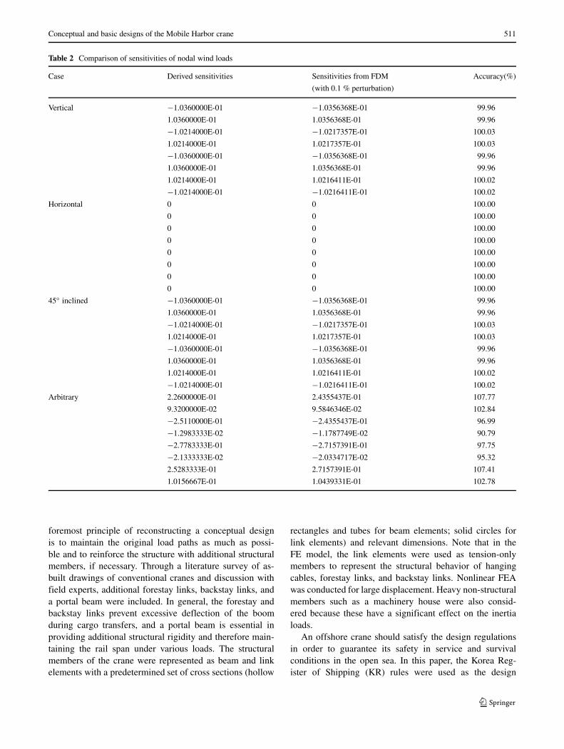
In order to verify sensitivities of nodal wind loads from(14), four case studies were conducted: a vertical case, ahorizontal case, a 45◦ inclined case, and an arbitrary case asshown Fig. 4. In all cases, the center elements are of interestand the red dotted lines represent their isovolumetric linesof μc = 0.5 with their nodal volume usages written. It wasassumed that the wind blows in the +x direction. Table 2demonstrates that the proposed scheme provides accuratesensitivities compared with those from the Finite DifferenceMethod (FDM) with a 0.1 % perturbation. When derivingthe wind loads and their sensitivities in this paper, the shapefunctions of a bilinear quadrilateral element were used andthe isovolumetric contour was approximated as a straightline in each element. Therefore, if a linear isovolumetriccontour exists in the element, accurate values of wind loadsand their sensitivities can be obtained. Conversely, if a non-linear contour is present, a certain amount of accuracy maybe lost. One simple remedy for accuracy is to increase themesh resolution in order to make the isovolumetric contourin each element uniform (or linear).
2.3 Conceptual design for Mobile Harbor
In order to set an appropriate design domain, the dimensionsof a target container ship and the Mobile Harbor were con-sidered; thus, the red rectangle in Fig. 5a was chosen as thedesign domain. Furthermore, the necessity of a crane boomto transport containers from the container side to the Mobile
Harbor side, and vice versa, was considered. Consideringthese points, the initial design domain was determined witha passive domain for the crane boom as shown with thecoordinate system in Fig. 5b. It is assumed that the geomet-ric boundary condition is fixed on the bottom of the initialdesign domain (i.e. y = 0 in Fig. 5b).
The operating conditions for the Mobile Harbor were setto the World Meteorological Organization (WMO) Sea State3. Under this condition, one of the collaborative researchteams conducted a ship motion analysis using WAMIT andWINPOST; 2.26 m/s2, 0.197 rad/s2, and 0.111 rad/s2 wereobtained as the maximum heave, roll, and pitch motions,respectively, at the center of mass of the Mobile Harbor.Then, these values were used to obtain the gravitationalloads and inertia loads from (5) and (6), respectively. Fur-thermore, 7.5 m/s and 51.5 m/s were used as the windvelocities under operating and survival conditions from theKR rulebook (listed in the reference) in order to obtain thewind loads from (12) and (13).
For the Mobile Harbor, the following four load caseswere used:
• Case 1: (payload 130.5 tons at the tip of a boom) + (roll0.197 rad/s2) + (heave 2.26 m/s2) + head wind (7.5 m/s)
• Case 2: (payload 130.5 tons at the end of a boom) + (roll0.197 rad/s2) + (heave 2.26 m/s2) + head wind (7.5 m/s)
• Case 3: (roll 0.197 rad/s2) + (heave 2.26 m/s2) + headwind (51.5 m/s)
• Case 4: (roll 0.197 rad/s2) + (heave 2.26 m/s2) + tailwind (51.5 m/s)
In Cases 1 and 2, the payload is derived under theassumption of
payload(ton) = {40(40f t container)+ 15(spreader)
+ 20(trolley)} × 1.45(impact f actor)
×1.2(dynamic f actor). (15)
The final formulation for the topology optimization isgiven as follows:
minimize
4∑j=1
cjFTj uj
subject to
n∑i=1
μiVi ≤ V0
μmin ≤ μi ≤ 1 i = 1, · · · , n (16)
where cj is the weighting factor and, in this paper, the samevalue of 0.25 was used for each load case.

510 I. G. Jang et al.
Fig. 4 Verification examples forsensitivities of nodal wind loads
0.255
0.255 0.75
0.75
0.255 0.255
0.75 0.75
(a) Vertical case (b) Horizontal case
0.502
0.132 0.502
0.875 0.378
0.450 0.700
0.725
(c) 45 inclined case (d) Arbitrary case
A two-dimensional FEA was performed using the com-mercial FEA package ANSYS. PLANE182 from the ele-ment library was used with the extra displacement shapeoption in order to avoid excessive shear stiffness (orso-called locking phenomena) in bending. For the optimiza-tion, the globally convergent method of moving asymp-totes (GCMMA), which was proposed by Svanberg (2002),was used. This algorithm was chosen because it can pro-vide non-monotonous approximations for design-dependentload problems. The optimization process was terminatedwhen the maximum variation of the design variables overtwo successive iterations was less than 0.01. The opti-mization converged in 227 iterations through the con-vergence history shown in Fig. 6a and it took 132 minwith Intel Core i7-950 CPU 3.07 GHz. It should benoted that, unlike typical compliance minimization prob-lems with dead loads, the sensitivities of the compliancein (4) are not always negative and therefore compliance
does not have a monotonous character with respect to thedesign variables. This property results in a significant dif-ficulty in searching for the optimum. Figure 6b presentsthe conceptual layout for the Mobile Harbor crane con-sidering the payload, self-weight, inertia load, and windload.
3 Shape optimization for basic design
In this section, the conceptual design obtained in Section 2is elaborated through shape optimization with detaileddesign regulations for offshore cranes. Such integrateddesign framework of the topology and shape optimizationhas been applied to structural design in aeronautics (Kroget al. 2002; James 2012).
In the first step, the basic design was reconstructed in3D (Fig. 7) from the original 2D conceptual design. The
Conceptual and basic designs of the Mobile Harbor crane 511
Table 2 Comparison of sensitivities of nodal wind loads
Case Derived sensitivities Sensitivities from FDM Accuracy(%)
(with 0.1 % perturbation)
Vertical −1.0360000E-01 −1.0356368E-01 99.96
1.0360000E-01 1.0356368E-01 99.96
−1.0214000E-01 −1.0217357E-01 100.03
1.0214000E-01 1.0217357E-01 100.03
−1.0360000E-01 −1.0356368E-01 99.96
1.0360000E-01 1.0356368E-01 99.96
1.0214000E-01 1.0216411E-01 100.02
−1.0214000E-01 −1.0216411E-01 100.02
Horizontal 0 0 100.00
0 0 100.00
0 0 100.00
0 0 100.00
0 0 100.00
0 0 100.00
0 0 100.00
0 0 100.00
45◦ inclined −1.0360000E-01 −1.0356368E-01 99.96
1.0360000E-01 1.0356368E-01 99.96
−1.0214000E-01 −1.0217357E-01 100.03
1.0214000E-01 1.0217357E-01 100.03
−1.0360000E-01 −1.0356368E-01 99.96
1.0360000E-01 1.0356368E-01 99.96
1.0214000E-01 1.0216411E-01 100.02
−1.0214000E-01 −1.0216411E-01 100.02
Arbitrary 2.2600000E-01 2.4355437E-01 107.77
9.3200000E-02 9.5846346E-02 102.84
−2.5110000E-01 −2.4355437E-01 96.99
−1.2983333E-02 −1.1787749E-02 90.79
−2.7783333E-01 −2.7157391E-01 97.75
−2.1333333E-02 −2.0334717E-02 95.32
2.5283333E-01 2.7157391E-01 107.41
1.0156667E-01 1.0439331E-01 102.78
foremost principle of reconstructing a conceptual designis to maintain the original load paths as much as possi-ble and to reinforce the structure with additional structuralmembers, if necessary. Through a literature survey of as-built drawings of conventional cranes and discussion withfield experts, additional forestay links, backstay links, anda portal beam were included. In general, the forestay andbackstay links prevent excessive deflection of the boomduring cargo transfers, and a portal beam is essential inproviding additional structural rigidity and therefore main-taining the rail span under various loads. The structuralmembers of the crane were represented as beam and linkelements with a predetermined set of cross sections (hollow
rectangles and tubes for beam elements; solid circles forlink elements) and relevant dimensions. Note that in theFE model, the link elements were used as tension-onlymembers to represent the structural behavior of hangingcables, forestay links, and backstay links. Nonlinear FEAwas conducted for large displacement. Heavy non-structuralmembers such as a machinery house were also consid-ered because these have a significant effect on the inertialoads.
An offshore crane should satisfy the design regulationsin order to guarantee its safety in service and survivalconditions in the open sea. In this paper, the Korea Reg-ister of Shipping (KR) rules were used as the design

512 I. G. Jang et al.
Fig. 5 Dimension and designdomain of the Mobile Harbor
(a) Dimensions of a target container ship and the Mobile Harbor
(b) Initial design domain of the Mobile Harbor
regulations. For the maximum allowable stress, 0.77 σYwas specified for the operating condition and 1.00 σY forthe survival condition, where σY is the yield stress of agiven material. For the members subjected to compres-sion, the allowable compressive stress should be verifiedas a measure of buckling strength using the followingequation:
ωσc, (17)
where σc is the axial compressive stress and ω can be cal-culated using the formula listed in Table 3. The detailedregulations are presented in the KR rulebook (listed inthe reference).
Considering all the aforementioned regulations with (17),the new formulation for shape optimization is given asfollows:
minimize
n∑i=1
mi
subject to σeqv,i ≤{
0.77σY in operating condition
1.00σY in survival condition
ωiσc,i ≤{
0.77σY in operating condition
1.00σY in survival condition
xlb,i ≤ xi ≤ xub,i, i = 1, · · · , 73 (18)
where mi is the mass of the ith structural member, andσeqv,i and σc,i denote von Mises equivalent stress and

Conceptual and basic designs of the Mobile Harbor crane 513
(a) Convergence history
(b) Final result
Fig. 6 Optimization history and result of topology optimization
Fig. 7 Reconstructed basic design with cross-sectional designvariables
Table 3 Formula for ω
Relation between Type of members Formula for ω
λ and λ0
λ ≥ λ0 All members 2.9(
λλ0
)2
λ < λ0 Plate members 1+0.45(λ/λ0)
1−0.5(λ/λ0)2
Cylindrical members 0.87+0.46(λ/λ0)+0.12(λ/λ0)2
1−0.5(λ/λ0)2
Note
λ = le
√A
I
where A is the sectional area of a member, I the moment of inertial ofthe section of a member, and le the effective length of the member
λ0 =√
2π2E
σy
where E is Young’s modulus and σy is the yield stress of material
compressive stress of the ith member, respectively. Massminimization is critical in the structural design of offshorecranes because it can reduce the overturning moment ofa ship. In (18), the design variables (xi) are the structuraldimensions for the cross section of each member (hollowrectangles and tubes for beam elements; solid circles for linkelements) as shown in Fig. 7, and their total number is 73.It should be noted that ωi in (18) is a function of the designvariables that are only related to the ith structural mem-ber. In this paper, the APDL (ANSYS Parametric DesignLanguage) program was developed to automatically calcu-late ωi from the current FE model. SM490YB was chosenas the structural steel because it is primarily used in marinestructures. More detailed material properties are listed inTable 4.
In the shape optimization, the following six load caseswere used (Cases 1–4 for operation conditions and Cases5–6 for survival conditions) considering the three-dimensional modeling:
• Case 1: (payload 130.5 tons at the tip of a boom) +(pitch 0.111 rad/s2) + (heave 2.26 m/s2)
• Case 2: (payload 130.5 tons at the tip of a boom) + (roll0.197 rad/s2) + (heave 2.26 m/s2)
Table 4 Material properties of SM490YB
Property Value
Young’s modulus 1.206 GPa
Poisson’s ratio 0.3
Density 7850 kg/m3
Yield stress 345 MPa

514 I. G. Jang et al.
Fig. 8 Optimization history ofshape optimization
• Case 3: (payload 130.5 tons at the middle of a boom) +(pitch 0.111 rad/s2) + (heave 2.26 m/s2)
• Case 4: (payload 130.5 tons at the middle of a boom) +(roll 0.197 rad/s2) + (heave 2.26 m/s2)
• Case 5: (pitch 0.111 rad/s2) + (heave 2.26 m/s2) +lateral wind (51.5 m/s)
• Case 6: (roll 0.197 rad/s2) + (heave 2.26 m/s2) + headwind (51.5 m/s)
An FEA was performed using BEAM188 and LINK180in ANSYS for the beam and tension-only members, respec-tively, and the modified method of feasible directions(MMFD) was used because it is known to be reliable and
to use less computer memory. The finite difference method(FDM) with 0.1 % perturbation was used to calculate thesensitivities required in the shape optimization. As shown inFig. 8, the optimization converged in 16 iterations and took401 min using an Intel Core i7-950 CPU 3.07 GHz. As aresult of the optimization, a mass reduction of 24.1 % wasachieved, even from the infeasible design (825.6 tons for theinitial design; 626.8 tons for the optimal design). Figure 9presents the optimized crane design satisfying design regu-lations. It is should be noted that the quayside crane, whichhas similar specifications (specifically, lifting capacity 50tons, rail span 30.5 m, outreach 51 m, and lifting height34 m), weighs 718.5 tons with SS400 and SM490YB forstructural parts.
Fig. 9 Optimized MobileHarbor crane

Conceptual and basic designs of the Mobile Harbor crane 515
4 Conclusion
In this paper, a conceptual layout of the Mobile Harborwas proposed with considerations of the design-dependentloads such as self-weight, inertia loads, and wind forces.These forces are essential in appropriately designing MobileHarbor cranes that operate under open sea conditions. Thesensitivities of the design-dependent loads were derived andthen applied to the topology optimization under multipleload cases. After obtaining the conceptual design, it waselaborated through shape optimization, which can deter-mine the cross-sectional dimensions required in order tosatisfy the design regulations. During the development ofthe Mobile Harbor, it is essential to reduce the structuralmass of the Mobile Harbor crane in order to enhance theoverall ship stability. Therefore, the basic design from themass minimization could successfully achieve this goal. Infurther research, a similar framework for topology optimiza-tion in 3D would be developed in order to obtain a moremeaningful conceptual design of the Mobile Harbor andthus propose a better basic design from it.
Acknowledgments This work was supported by the IndustrialStrategic Technology Development Program (10036235, Developmentof the core technology of light weight crane for mobile harbor) fundedby the Ministry of Knowledge Economy (MKE, Korea). We wouldlike to thank Dr. Krister Svanberg at KTH (Stockholm, Sweden) forproviding the GCMMA code for academic research.
References
Bendsoe MP (1989) Optimal shape design as a material distributionproblem. Struct Optim 1:193–303
Bendsoe MP, Kikuchi N (1988) Generating optimal topologiesin structural design using a homogenization method. ComputMethod Appl Mech Eng 71:197–224
Bruyneel M, Duysinx P (2005) Note on topology optimization of con-tinuum structures including self-weight. Struct Multidiscip Optim29:245–256
Du J, Olhoff N (2004a) Topological optimization of continuum struc-tures with design-dependent surface loading - part I: new com-putational approach for 2D problems. Struct Multidiscip Optim27(3):151–165
Du J, Olhoff N (2004b) Topological optimization of continuumstructures with design-dependent surface loading - part II: algo-rithm and examples for 3D problems. Struct Multidiscip Optim27(3):166–177
Hammer VB, Olhoff N (2000) Topology optimization of continuumstructures subjected to pressure loading. Struct Multidiscip Optim19:85–92
Hassani B, Hinton E (1998) A review of homogenization and topologyoptimization I—homogenization theory for media with periodicstructure. Comput Struct 69:707–717
James K (2012) Aerostructural shape and topology optimization ofaircraft wings. Ph.D. thesis, University of Toronto
Jang IG, Kim IY (2009) Computational simulation of trabecularadaptation progress in human proximal femur during growth. JBiomech 42(5):573–580
Jang IG, Kim IY (2010) Application of design space optimization tobone remodeling simulation of trabecular architecture in humanproximal femur for higher computational efficiency. Finite ElemAnal Des 46(4):311–319
Jang IG, Kwak BM (2006) Evolutionary topology optimization usingdesign space adjustment based on fixed grid. Int J Numer MethodEng 66(11):1817–1840
Jang IG, Kwak BM (2008) Design space optimization using designspace adjustment and refinement. Struct Multidiscip Optim35(1):41–54
Kim IY, Kwak BM (2002) Design space optimization using anumerical design continuation method. Int J Numer Method Eng53:1979–2002
Kim EH, Kwak KW, Kim YK, Kim SH, Kwak BM, Jang IG, Kim KS(2013) Auto-positioning of sliding planes based on virtual force.Int J Control Autom Syst 11(4):798–804
Kim EH, Jung YS, Yu YG, Kwon SW, Ju HJ, Kim SH, KwakBM, Jang IG, Kim KS (2014) An advanced cargo handling sys-tem operating at sea. Int J Control Autom Syst. doi:10.1007/s12555-013-0189-3
KR rule book, www.krs.co.kr/KRRules/KRRules2011/KRRulesE.html
Krog L, Tucker A, Rollema G (2002) Application of topology, siz-ing, and shape optimization methods to optimal design of aircraftcomponents. In: Proceedings of 3rd Altair UK HyperWorks usersconference
Osher S, Sethian JA (1988) Front propagating with curvature depen-dent speed: algorithms based on Hamilton–Jacobi formulations. JComput Phys 78:12–49
Park KS, Chang SY, Youn SK (2003) Topology optimization of the pri-mary mirror of a multi-spectral camera. Struct Multidiscip Optim25:46–53
Pedersen N (2000) Maximization of eigenvalues using topology opti-mization. Struct Multidiscip Optim 20:2–11
Querin OM, Steven GP, Xie YM (1998) Evolutionary structural opti-mization (ESO) using a bidirectional algorithm. Eng Comput15:1031–1048
Stolpe M, Svanberg K (2001) An alternative interpolation scheme forminimum compliance topology optimization. Struct MultidiscipOptim 22:116–224
Svanberg K (2002) A class of globally convergent optimizationmethods based on conservative convex separable approximations.SIAM J Optim 12:555–573
Wang MY, Wang X, Guo D (2003) A level set method for structuraltopology optimization. Comput Method Appl Mech Eng 192:227–246
Xie YM, Steven GP (1993) A simple evolutionary procedure forstructural optimization. Comput Struct 49:885–896
Yang RJ, Chuang CH (1994) Optimal topology design using linearprogramming. Comput Struct 52:265–275
Zhang H, Zhang X, Liu S (2008) A new boundary search schemefor topology optimization of continuum structures with design-dependent loads. Struct Multidiscip Optim 37(2):121–129
Zakhama R, Abdalla MM, Gurdal Z, Smaoui H (2010) Wind loadmodeling for topology optimization of continuum structures.Struct Multidiscip Optim 42(1):157–164


![MOBILE HARBOUR CRANE SPREADERS - Bromma€¦ · mobile harbor crane spreaders includes single-lift options such as the EH5U spreader [capable of handling 20’ or 40’ containers];](https://static.fdocuments.net/doc/165x107/604b5b3a9388356f1e7baec6/mobile-harbour-crane-spreaders-bromma-mobile-harbor-crane-spreaders-includes-single-lift.jpg)