Development of Informative Path Planning for Inspection of ...
7
Development of Informative Path Planning for Inspection of the Hanford Tank Farm Sebasti´ an A. Zanlongo 1 , Leonardo Bobadilla 1 , Dwayne McDaniel 2 , Yew Teck Tan 2 Abstract—Traditional environmental and structural monitor- ing often uses static sensor networks deployed at predetermined locations or mobile robots that use a rastering technique for area coverage. These methods rely on the operators making assumptions about the nature of the unknown field that is being measured and are often time-consuming for localizing an area of interest. Here, we aim to quickly localize possible leaks within high-level nuclear waste tanks at the Hanford facility. The structure of these tanks precludes most sensor network approaches and raises many issues with robotic inspection, such as navigation within highly constrained environments. This work uses a Bayesian Optimization approach for guiding a mobile robot’s search strategy and implements a utility function that allows for prior knowledge of the structure to be incorporated when selecting future search locations. Compared to traditional exhaustive approaches, our method quickly reduces RMSE error and shortens the distance the robot must travel. I. INTRODUCTION During World War II and the Manhattan Project, large amounts of high-level radioactive waste were generated. Some of these wastes are in liquid form and stored in large double-shell tanks at the Hanford Facility in Washington state. These structures are now in a surveillance and mainte- nance phase requiring continuous monitoring to check for containment failures. Contamination of these and similar structures can result from leakage, and one tank has been confirmed to have leaked [1]. Localizing the source of these potential leaks is difficult due to the structure of the tank: the tanks are buried approx- imately 4.5m underground, and the bottom of the tank is another 14m deeper with a diameter of 23m, as illustrated in Figure 2(a) [2]. Inspection of the structural integrity of the tanks can only be accessed via narrow annuli at ground level, further complicating sensor deployment. Moreover, this only serves to reach the tank along its perimeter. Access to the rest of the tank bottom must be done through a series of narrow ∼4cm cooling refractory slots located at the bottom of the tank. We might consider deploying a sensor network throughout the refractory slots. However, the sensors may interfere with the air being circulated through the slots, or the moving air could dislodge the sensors. Moreover, deployment in such a constrained environment faces the issues of how to transport and attach the sensors, and how to power and 1 Sebasti´ an A. Zanlongo and Leonardo Bobadilla are with the School of Computing and Information Sciences, Florida Interna- tional University, Miami, FL 33199, USA [email protected], [email protected] 2 Yew Teck Tan and Dwayne McDaniel are with the Applied Research Center, Florida International University, Miami, FL 33199, USA {yetan, mcdaniel}@fiu.edu communicate with them over extended periods. Existing inspection approaches use a pole-mounted camera; however, this can only inspect the perimeter of the tank and the outermost segment of the refractory slots. Furthermore, pole- mounted visual inspection requires that operators manually inspect each of the refractory slots [3], leading to a labor- intensive, time-consuming process. There are sampling methods such as [4] which attempt to perform a spatial extrapolation given samples at selected discrete locations. Care must be taken when selecting and adapting a sampling approach, as an inappropriate regres- sion model or utility function may cause problems ranging from non-representative samples to overlooking an important location. Furthermore, inaccurate estimations of the spatial variability can lead to incorrect modeling of the underlying field and contamination properties. In this paper, we present a methodology for automat- ing and improving the inspection process of these tanks. We propose an Adaptive Informative Path Planning (IPP) approach that would allow a miniature robotic rover to inspect the tank for locations of interest efficiently. The IPP algorithm incorporates prior knowledge about the tank structure, balances exploration and exploitation to initially locate and then refine the points of interest, and also accounts for the robot’s movement constraints. The rest of the paper is organized as follows: In Section II, we review existing approaches to IPP, including relevant similarities, and the major differences to our domain. In Section III, we define the environment and problem being tackled, and Section IV describes our approach. Sections V and VI cover the simulated trials, and an analysis of the results. In Sections VII and VIII we offer a discussion of the results obtained and final conclusions. II. RELATED WORK IPP has broad applicability, used to localize points of interest in forests, oceans, and disaster areas [5], and contains myriad domain-specific issues which can render existing approaches insufficient. Traditional localization such as [6] often uses a rastering (zig-zag) pattern to cover an area to map it, or execute a minimum-cost tour of locations deter- mined to be most informative a priori [7]. These approaches may take a long time to localize the source if it is opposite to the starting position. Adaptive sampling aims to provide better results with less time by actively adapting its sampling locations. In this work, we utilize a modified Gaussian Process - Upper Confidence Bound approach (GP-UCB) [8] to efficiently
Transcript of Development of Informative Path Planning for Inspection of ...
Development of Informative Path Planning for Inspection of theHanford Tank Farm
Sebastian A. Zanlongo1, Leonardo Bobadilla1, Dwayne McDaniel2, Yew Teck Tan2
Abstract— Traditional environmental and structural monitor-ing often uses static sensor networks deployed at predeterminedlocations or mobile robots that use a rastering technique forarea coverage. These methods rely on the operators makingassumptions about the nature of the unknown field that isbeing measured and are often time-consuming for localizing anarea of interest. Here, we aim to quickly localize possible leakswithin high-level nuclear waste tanks at the Hanford facility.The structure of these tanks precludes most sensor networkapproaches and raises many issues with robotic inspection,such as navigation within highly constrained environments.This work uses a Bayesian Optimization approach for guidinga mobile robot’s search strategy and implements a utilityfunction that allows for prior knowledge of the structureto be incorporated when selecting future search locations.Compared to traditional exhaustive approaches, our methodquickly reduces RMSE error and shortens the distance therobot must travel.
I. INTRODUCTIONDuring World War II and the Manhattan Project, large
amounts of high-level radioactive waste were generated.Some of these wastes are in liquid form and stored in largedouble-shell tanks at the Hanford Facility in Washingtonstate. These structures are now in a surveillance and mainte-nance phase requiring continuous monitoring to check forcontainment failures. Contamination of these and similarstructures can result from leakage, and one tank has beenconfirmed to have leaked [1].
Localizing the source of these potential leaks is difficultdue to the structure of the tank: the tanks are buried approx-imately 4.5m underground, and the bottom of the tank isanother 14m deeper with a diameter of 23m, as illustrated inFigure 2(a) [2]. Inspection of the structural integrity of thetanks can only be accessed via narrow annuli at ground level,further complicating sensor deployment. Moreover, this onlyserves to reach the tank along its perimeter. Access to therest of the tank bottom must be done through a series ofnarrow ∼4cm cooling refractory slots located at the bottomof the tank. We might consider deploying a sensor networkthroughout the refractory slots. However, the sensors mayinterfere with the air being circulated through the slots, or themoving air could dislodge the sensors. Moreover, deploymentin such a constrained environment faces the issues of howto transport and attach the sensors, and how to power and
1Sebastian A. Zanlongo and Leonardo Bobadilla are with theSchool of Computing and Information Sciences, Florida Interna-tional University, Miami, FL 33199, USA [email protected],[email protected]
2Yew Teck Tan and Dwayne McDaniel are with the Applied ResearchCenter, Florida International University, Miami, FL 33199, USA {yetan,mcdaniel}@fiu.edu
communicate with them over extended periods. Existinginspection approaches use a pole-mounted camera; however,this can only inspect the perimeter of the tank and theoutermost segment of the refractory slots. Furthermore, pole-mounted visual inspection requires that operators manuallyinspect each of the refractory slots [3], leading to a labor-intensive, time-consuming process.
There are sampling methods such as [4] which attemptto perform a spatial extrapolation given samples at selecteddiscrete locations. Care must be taken when selecting andadapting a sampling approach, as an inappropriate regres-sion model or utility function may cause problems rangingfrom non-representative samples to overlooking an importantlocation. Furthermore, inaccurate estimations of the spatialvariability can lead to incorrect modeling of the underlyingfield and contamination properties.
In this paper, we present a methodology for automat-ing and improving the inspection process of these tanks.We propose an Adaptive Informative Path Planning (IPP)approach that would allow a miniature robotic rover toinspect the tank for locations of interest efficiently. TheIPP algorithm incorporates prior knowledge about the tankstructure, balances exploration and exploitation to initiallylocate and then refine the points of interest, and also accountsfor the robot’s movement constraints.
The rest of the paper is organized as follows: In SectionII, we review existing approaches to IPP, including relevantsimilarities, and the major differences to our domain. InSection III, we define the environment and problem beingtackled, and Section IV describes our approach. Sections Vand VI cover the simulated trials, and an analysis of theresults. In Sections VII and VIII we offer a discussion ofthe results obtained and final conclusions.
II. RELATED WORK
IPP has broad applicability, used to localize points ofinterest in forests, oceans, and disaster areas [5], and containsmyriad domain-specific issues which can render existingapproaches insufficient. Traditional localization such as [6]often uses a rastering (zig-zag) pattern to cover an area tomap it, or execute a minimum-cost tour of locations deter-mined to be most informative a priori [7]. These approachesmay take a long time to localize the source if it is oppositeto the starting position.
Adaptive sampling aims to provide better results withless time by actively adapting its sampling locations. Inthis work, we utilize a modified Gaussian Process - UpperConfidence Bound approach (GP-UCB) [8] to efficiently

select sampling locations. The goal is to deploy a roboticsystem for localizing radioactive leaks, and thus has somesimilarities to [9], [10] where robots are fitted with opticaland radiation sensors to find radiation sources, and [11]which has a strong showing of aerial vehicles and theirassociated mapping techniques. The approach in this paperdiffers in its unique environment and the resulting constraintssuch as limited robot movement.
Unlike some existing IPP approaches which rely purelyon the informativeness of possible sampling locations [12],we also incorporate robot dynamics such as movement andtether constraints that limit the robot’s ability to visit specificlocations easily. This idea bears some resemblance to workby [13], [14] where a Gaussian Process is used to modelboth the phenomenon and the quality of possible paths. Withregards to path-planning, we look to Brass et al. [15] whichperforms path planning for a tethered robot given polygonalobstacles, and Kim et al. [16] which use a Multi-Heuristic A∗
algorithm to find paths for a tethered robot with a homotopyinvariant augmented graph. For the robot to navigate betweenthe vertices in the graph representation of the refractory slots,we use a modified A∗ algorithm similar to that of [17].
III. PROBLEM FORMULATION
The goal of inspecting the tanks is to detect anomalies- in this case, leaks. As a proxy for finding the leak, weuse the temperature distribution at the bottom of the tank,which would be impacted by the presence of a leak. Weseek to create a map of the temperature distribution at thebottom of the tank - which is represented by an unknownscalar field f : Rd → R, from samples Y selected from aset of potential sampling locations V . Given the samples,we wish to find the location with the highest temperature,corresponding to the most likely source of a leak. Moreover,we desire to select the sampling locations which best updatethe model, but also reduce the overall distance traveled whilerespecting the kinematic constraints of the robot. Completecoverage would map out the entire tank, lending itself to anexhaustive approach. This formulation instead seeks to findthe leak more quickly than a traditional exhaustive approach.
The approach and simulation in this work were designedfor deployment in the Hanford facility double-shell tanks.These tanks are composed of an inner tank that holds thehigh-level liquid radioactive waste and an outer shell servingas a fail-safe if the inner tank leaks. Figure 1 illustrates acutaway view of the tank, indicating the inner storage vessel,refractory slots, and the gap between the inner and outer tankwalls. Here, we will describe the structure in further detail.
A. Refractory Slot Structure
Sandwiched between the bottom of the two tanks is aseries of air distribution slots seen in Figure 1, also knownas refractory slots. This system cools the primary tank andprovides an avenue for inspecting the bottom of the innertank without actually entering the tank itself. The tanks werebuilt over multiple years and have slightly varying refractoryslot designs. We focus on the design of the AY-series tanks,
Fig. 1: Tank cutaway showing the inner and outer shells,refractory slots, and annulus at the sides of the tanks.
(a) (b)
(c)
Fig. 2: Tank Structure
(a) Tank cutaway showing buried tank and access annulus. (b) Thelayout of the refractory slots at the bottom of the tanks. (c) Viewfrom (b) with the addition of weld seams. (d) View from (c), withlocations where refractory slots intersect weld seams highlighted.
which consist of ∼4cm-wide slots arrayed radially outwardsas in Figure 2(b).
We model the refractory slots as a graph, with the slotsrepresented as edges E, and the forks as vertices V . Therobot cannot execute tight turns (cannot turn at a fork to godown a parallel slot). Given this graph structure, we onlyconsidered vertices as valid sampling locations, rather thanthe continuous plane representing the tank floor. As such, weintroduce additional evenly-spaced vertices along edges suchthat a minimum desired sampling resolution is achieved.
The bottom of the tank is formed by multiple steel plateswelded together, meaning that there are weld seams between
the various plates. These weld seams run in a pattern as inFigure 2(c), with occasional overlaps along the refractoryslots indicated by the purple points in Figure 2(d). Manyof the seams had initial high rejection rates, and have beenreworked [18]. Due to the rework, their integrity may becompromised, making them of higher interest.
B. Temperature Distribution Modeling
Searching for the leak, we might initially consider search-ing for the liquid that has leaked out. However, there are con-founding factors such as seepage from other sources, as wellas desiring to avoid the robot coming into contact with thecontamination. We might also mount a radiation sensor to therobot; however, a typical radiation sensor would not fit withina refractory slot. Moreover, radiation roughly follows aninverse-square law, making localization difficult. Instead, welook towards temperature as a proxy measurement as thesesensors are small and sensitive to temperature variations.The Gaussian nature of temperature assists in localizing theleak. The source of the leak corresponds to the peak, andmoving further away from the leak leads to a decaying signal.The model was generated using a 2-dimensional multivariatenormal distribution with a probability density function suchas that in [19], with mean vector M , a randomly-generatedpositive definite covariance matrix Σ. Further details aboutthe model can be found in Section V.
C. Regression
Gaussian Processes provide a method for modeling un-known fields non-parametrically. Here, we aim to efficientlyderive a Gaussian Process regression through a processsuch as that described in [19]. Given a set of N samplinglocations, each location xi ∈ R2 has a noisy measurementyi ∈ R given by y = f(x)+ε where f(x) is the ground-truthand ε ∼ N (0, σ2
n). The predicted mean u∗ and covarianceσ∗ at a specific target location x∗ ∈ X∗ is given by:µ(x∗) = K(x∗, X)K−1X yσ(x∗) = K(x∗, x∗)−K(x∗, X)K−1X (X,x∗)where K(X ′, X ′′) is the covariance matrix, X are the
sampled observation locations, and KX = K(X,X) + σ2nI .
For the covariance function, our implementation uses aMatern kernel. This kernel was chosen as a finitely differen-tiable kernel can better model physical processes, and doesnot assume as much smoothness as other kernels - such as theinfinitely differentiable Squared Exponential kernel - whichcan yield unrealistically smooth results when modeling aphysical process [20]. The Matern kernel is described as:
k(xi, xj) = σ2 21−ν
Γ(ν)
(√2νd
ρ
)νKν
(√2νd
ρ
)(1)
Here, xi, xj are two locations and d is the distancebetween them, which is parameterized by ρ > 0. We controlthe smoothness of the function via ν > 0. Γ is the gammafunction, and Kν is the modified Bessel function of thesecond kind [19]. We select ν = 1.5 (a once-differentiablefunction) to avoid having to compute the Bessel function,allowing for a roughly 10 times faster computation. For
optimizing the kernel’s parameters, we use the Limited-memory BFGS (L-BFGS-B) [21] optimization algorithm,which has linear memory usage. The first run of L-BFGS-B is done with the kernel’s initial parameters, and then anadditional n restarts using θ derived from a random log-uniform distribution within the allowed bounds.
D. Robot
In this work, we model the robot as a point robot, capableof moving along edges in the graph from one vertex toanother. To simplify the problem, we assumed a movementspeed of 0.3m/s and a sampling time of 10s when measuringthe temperature at a location. The robot has a tether, whichwas selected to be long enough to allow the robot to accessany point in the refractory slots, but short enough that thefurthest location would require using all the length of thetether with minimal slack. This tether is needed to:• Power the robot• Send / receive commands and sensor data• Allow for removal of robot in event of system failureThe tether limits the distance the robot can travel and
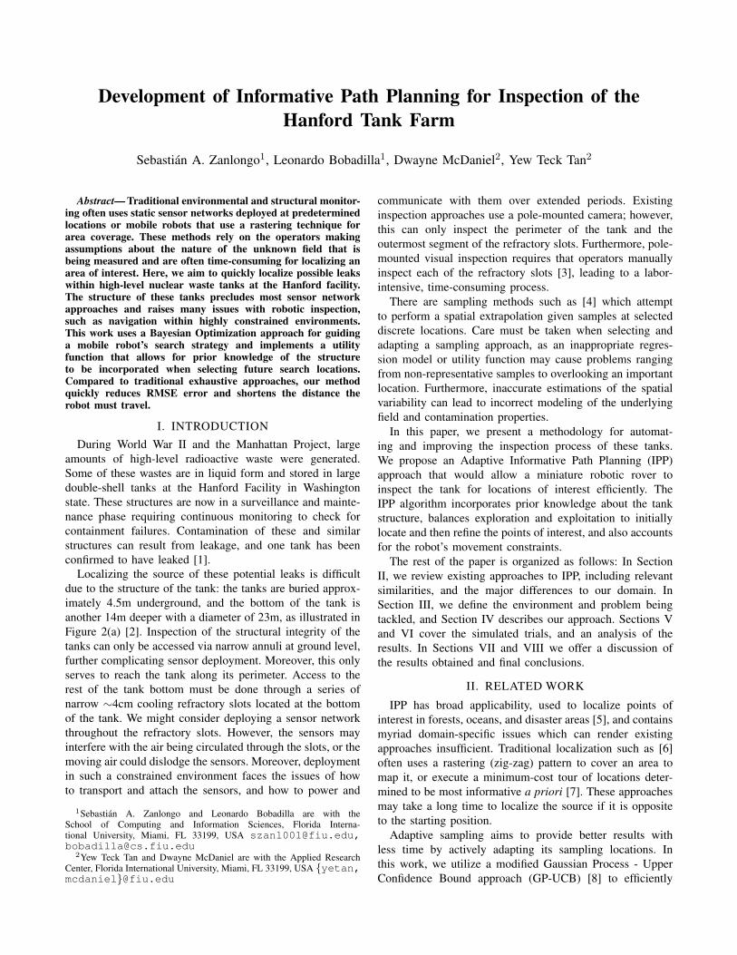
constrains its movement (loops and tight turns are notpossible). The most noticeable effect of the tether is that therobot cannot completely circle the tank, and must insteadretract to the insertion point and then go the other directionwhen reaching locations on the far side of the tank. Thisconstraint can be seen in Figure 3(d), where the robot mustcircle back before exploring the other half of the tank.
IV. GAUSSIAN PROCESS MODELING ANDSAMPLING LOCATION SELECTION
We begin by accepting as input a graph (G = (V,E))representation of the refractory slots, and discretizing thegraph to the desired resolution by inserting additional ver-tices along the edges as needed. This process allows us toapproximate the continuous sampling space using a simplerdiscrete representation. The vertices also encode the anglesbetween each other, preventing the robot from attemptingtight turns which would cause the tether to become stuck.
These restrictive constraints permit the solution to be usedin similar environments such as the tanks at the Savan-nah River National Laboratory [22], or the Waste IsolationProcessing Plant (WIPP), which also has a channel-likestructure. This method can also be applied to more traditionalopen environments. If a graph structure is not initiallyavailable, a Voronoi decomposition or cell decomposition[23] may be used to generate a graph.
The approach consists of a modified Upper ConfidenceBound algorithm: Given the current state of a GaussianProcess Regression, we use the predictive output mean µ∗
(Exploitation) and variance σ∗ (Exploration) at the candidatesampling locations S, which is initially equivalent to V .Weld seam bias w serves to increase the expected utilityof prospective sampling locations that lie on top of a weldseam, given the expected higher failure rate of weld seamsdue to their high initial rejection rate.
(a) (b)
(c) (d)
Fig. 3: Example Robot Trajectory
(a) Isometric view of a Gaussian-Process-like temperature distribu-tion (with the peak being the leak source) overlaid on refractoryslots. (b) Overhead view of (a). (c) Example time representation ofa robot moving through refractory slots, where the vertical z-axis ismovement through time. (d) Time representation of a robot movingthrough refractory slots using an exhaustive approach.
The exploitation and exploration values are normalized ateach step t ∈ T , with regards to the highest-valued predictedoutput in the set S. The weld seam value is set to a constantw = 1. These elements are then respectively weighted by λ,where ∀i ∈ λ|i ∈ [0, 1] to yield: utility = λ · [µ∗, σ∗, w],such that utility ∈ [0, 3], where locations with a higher valueare deemed more desirable.
We will now cover each of the parameters in detail, andhow they affect the model’s behavior.
1) Exploration vs Exploitation: We begin by discussingthe most critical component of the modified UCB algorithm:the trade-off between exploration and exploitation.
We start by constructing a distribution that describes theGaussian Process we are looking to reconstruct. Adding moreobservations, the distribution improves, and the uncertainty(variance) diminishes near sampled locations allowing usto determine which locations need to be further explored.The UCB algorithm shown in Algorithm 1 is drawn from[13], [24], and selects a new sampling location based on theweighted mean and variance. A higher mean biases to rapidlocalization and a higher variance to total coverage. Thisprocess is done by finding the maximum of the UCB utilityfunction, which serves as a computationally simpler proxyfor the task of regression [25], [26]. We must also set α,
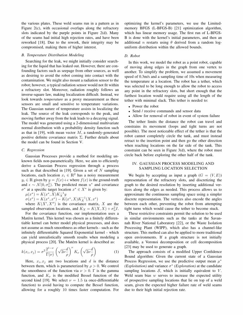
Algorithm 1: Bayesian Optimization
1: Input: Possible sampling locations V , Utility functionU , Update Rate r, Number of samples to take n
2: S′ ← V3: for t ∈ [1, n] do4: Evaluate U(s) over S′
5: x← argmax U(s)6: Sample(x)7: S′ ← S′\x8: if t%r == 0 then9: UpdateGP (x)
which is the value added to the diagonal of the kernel matrixwhen fitting the model. Small values correspond to less noise,whereas high values indicate greater noise, equivalent tousing an additional White Kernel. Here, we set α = 0.2,which roughly correlates to the +/ − 2◦C error margin ofthe temperature sensor model.
2) Weld-Seam Bias: The previous section assumes thatthe only way to gather information is via new samples.However, we know that the weld seams are more prone tofailure than the steel plates themselves. With this in mind,we can bias our search to prioritize weld seams that intersectour available sampling locations (Figure 2(d)) by adding theweighted parameter w to the utility function. For verticesthat lie on a weld seam x ∈ Vweld, we add the weighted wto the utility; otherwise, the value is 0.
V. SIMULATION
Simulation consisted of a series of 200 independent trials,each with a randomly generated hot-spot representing a leak.The hot-spots exhibit a distribution that can be describedby a Gaussian Process, and the peak of each hot-spot lieswithin the bounds of the tank. One hundred of these trialshad the hot-spot centered on a randomly-selected locationalong a weld seam, to reflect the higher failure rate expectedof weld seams compared to the plates themselves. The other100 trials had the hot-spot generated at a random locationwithin the bounds of the tank. A visualization of this can befound in Figure 4.
Without loss of generality, the hot-spot peak intensity(mean) was set to 100, while the covariance along the x, yaxes was randomly selected from the range [4.5, 18]. Thisrange was selected as 4.5m is approximately the maximumdistance between two refractory slots - therefore the mini-mum size for at least one refractory slot to intersects the hot-spot. The upper value of 18m corresponds to 4 times 4.5 andwas used to provide a varying range of spread. The resultinghot-spot was then used to evaluate the various weightingschemes.
While executing a trajectory, the robot would sample ifit visited a previously un-sampled location, and remove thatlocation from the candidate pool of future sampling locationsS. The regression was fitted at every 3rd new sample. Thisprocess continued until all vertices in the graph had been
(a) (b)
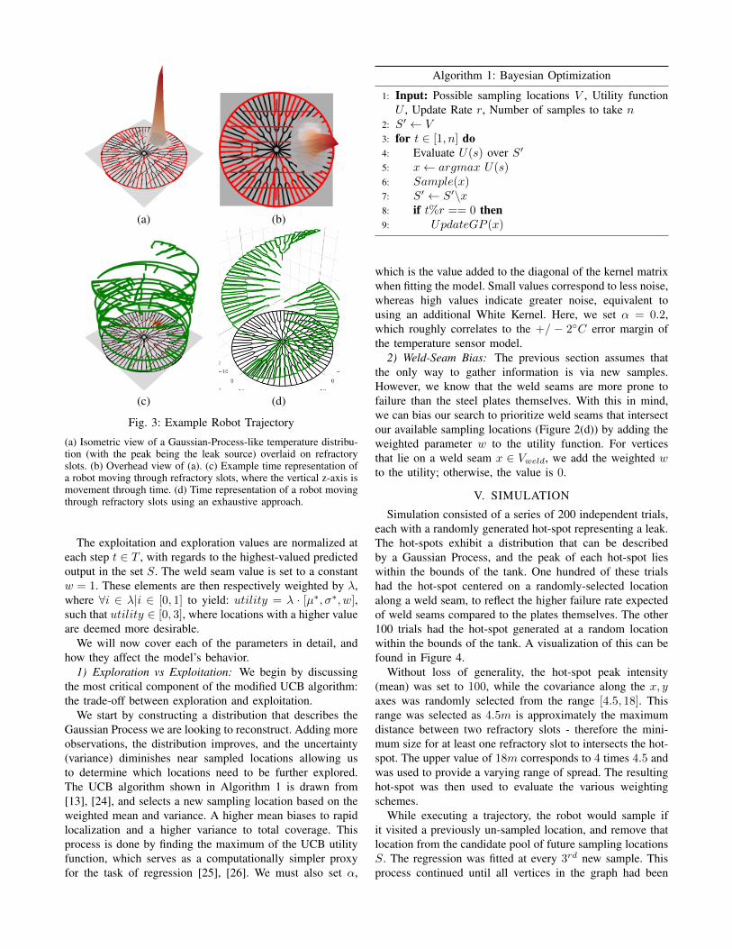
Fig. 4: Example visualization of distributions.
(a) Averaged location of distributions centered on a random locationcoinciding with a weld-seam over 100 trials. (b) Averaged locationof distributions placed randomly throughout the tank over 100 trials.On average 3ft away from the nearest weld seam.
visited and sampled. Apart from IPP, an exhaustive approachwas executed against the same distributions to establish abaseline. The exhaustive approach used the trajectory shownin Figure 3(d) where x, y are the planar coordinates, and zrepresents time.
The algorithm terminates when there are no more samplinglocations. An operator could ostensibly specify stoppingcriteria of either a minimum overall variance or if a highenough signal is found (which would be known ahead oftime given the contents of the tank).
VI. ANALYSIS
Testing of the different weighting schemes was done bycomparing their Root Mean Square Error (RMSE) for thepredicted value at locations throughout the tank, defined as:RMSE(µ) =
√1n
∑ni=1(Yi − Yi)2 where Y is the vector
of ground-truth values, and Y is the vector of n predictions.The resulting non-negative loss-value is a measure of
accuracy indicating the difference between the predictedvalues and the ground truth, where a value of 0 is the bestscore, and larger values correspond to a worse-performingmodel. We will also refer to “local RMSE” as the RMSE fora region surrounding the distributions’ center, with a diameterof 1σ, the spread given by the covariance of the distribution.This is done to illustrate the performance of the regressionfor the point of interest, rather than the entire area.
A. Illustrative Examples
In this section, we outline the weighting schemes that bestillustrate how different strategies can affect the performanceof the approach described above.
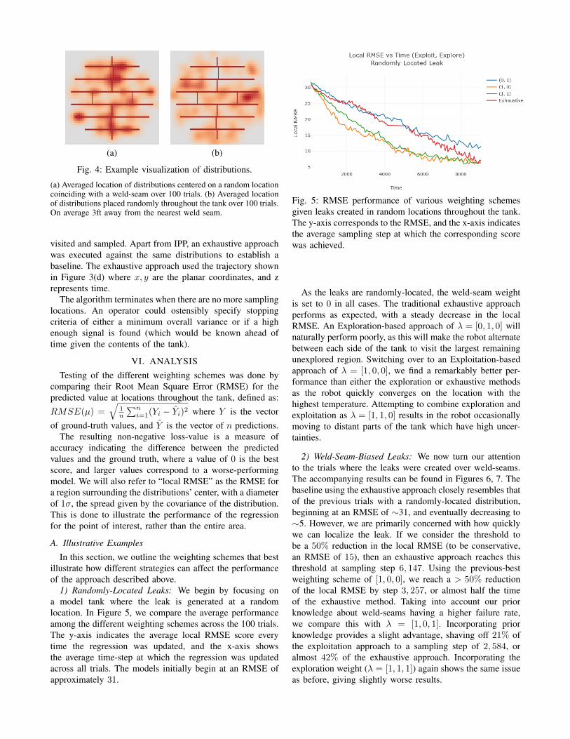
1) Randomly-Located Leaks: We begin by focusing ona model tank where the leak is generated at a randomlocation. In Figure 5, we compare the average performanceamong the different weighting schemes across the 100 trials.The y-axis indicates the average local RMSE score everytime the regression was updated, and the x-axis showsthe average time-step at which the regression was updatedacross all trials. The models initially begin at an RMSE ofapproximately 31.
Fig. 5: RMSE performance of various weighting schemesgiven leaks created in random locations throughout the tank.The y-axis corresponds to the RMSE, and the x-axis indicatesthe average sampling step at which the corresponding scorewas achieved.
As the leaks are randomly-located, the weld-seam weightis set to 0 in all cases. The traditional exhaustive approachperforms as expected, with a steady decrease in the localRMSE. An Exploration-based approach of λ = [0, 1, 0] willnaturally perform poorly, as this will make the robot alternatebetween each side of the tank to visit the largest remainingunexplored region. Switching over to an Exploitation-basedapproach of λ = [1, 0, 0], we find a remarkably better per-formance than either the exploration or exhaustive methodsas the robot quickly converges on the location with thehighest temperature. Attempting to combine exploration andexploitation as λ = [1, 1, 0] results in the robot occasionallymoving to distant parts of the tank which have high uncer-tainties.
2) Weld-Seam-Biased Leaks: We now turn our attentionto the trials where the leaks were created over weld-seams.The accompanying results can be found in Figures 6, 7. Thebaseline using the exhaustive approach closely resembles thatof the previous trials with a randomly-located distribution,beginning at an RMSE of ∼31, and eventually decreasing to∼5. However, we are primarily concerned with how quicklywe can localize the leak. If we consider the threshold tobe a 50% reduction in the local RMSE (to be conservative,an RMSE of 15), then an exhaustive approach reaches thisthreshold at sampling step 6, 147. Using the previous-bestweighting scheme of [1, 0, 0], we reach a > 50% reductionof the local RMSE by step 3, 257, or almost half the timeof the exhaustive method. Taking into account our priorknowledge about weld-seams having a higher failure rate,we compare this with λ = [1, 0, 1]. Incorporating priorknowledge provides a slight advantage, shaving off 21% ofthe exploitation approach to a sampling step of 2, 584, oralmost 42% of the exhaustive approach. Incorporating theexploration weight (λ = [1, 1, 1]) again shows the same issueas before, giving slightly worse results.
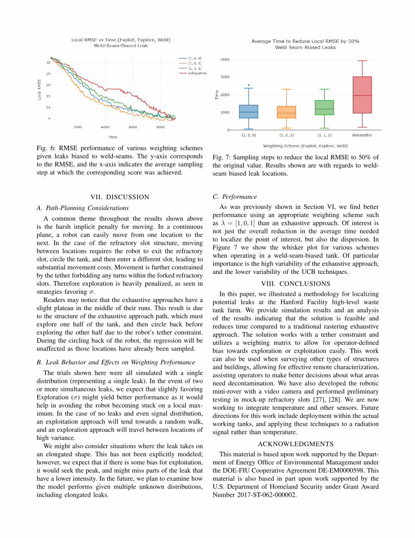
Fig. 6: RMSE performance of various weighting schemesgiven leaks biased to weld-seams. The y-axis correspondsto the RMSE, and the x-axis indicates the average samplingstep at which the corresponding score was achieved.
VII. DISCUSSION
A. Path-Planning Considerations
A common theme throughout the results shown aboveis the harsh implicit penalty for moving. In a continuousplane, a robot can easily move from one location to thenext. In the case of the refractory slot structure, movingbetween locations requires the robot to exit the refractoryslot, circle the tank, and then enter a different slot, leading tosubstantial movement costs. Movement is further constrainedby the tether forbidding any turns within the forked refractoryslots. Therefore exploration is heavily penalized, as seen instrategies favoring σ.
Readers may notice that the exhaustive approaches have aslight plateau in the middle of their runs. This result is dueto the structure of the exhaustive approach path, which mustexplore one half of the tank, and then circle back beforeexploring the other half due to the robot’s tether constraint.During the circling back of the robot, the regression will beunaffected as those locations have already been sampled.
B. Leak Behavior and Effects on Weighting Performance
The trials shown here were all simulated with a singledistribution (representing a single leak). In the event of twoor more simultaneous leaks, we expect that slightly favoringExploration (σ) might yield better performance as it wouldhelp in avoiding the robot becoming stuck on a local max-imum. In the case of no leaks and even signal distribution,an exploitation approach will tend towards a random walk,and an exploration approach will travel between locations ofhigh variance.
We might also consider situations where the leak takes onan elongated shape. This has not been explicitly modeled;however, we expect that if there is some bias for exploitation,it would seek the peak, and might miss parts of the leak thathave a lower intensity. In the future, we plan to examine howthe model performs given multiple unknown distributions,including elongated leaks.
Fig. 7: Sampling steps to reduce the local RMSE to 50% ofthe original value. Results shown are with regards to weld-seam biased leak locations.
C. Performance
As was previously shown in Section VI, we find betterperformance using an appropriate weighting scheme suchas λ = [1, 0, 1] than an exhaustive approach. Of interest isnot just the overall reduction in the average time neededto localize the point of interest, but also the dispersion. InFigure 7 we show the whisker plot for various schemeswhen operating in a weld-seam-biased tank. Of particularimportance is the high variability of the exhaustive approach,and the lower variability of the UCB techniques.
VIII. CONCLUSIONSIn this paper, we illustrated a methodology for localizing
potential leaks at the Hanford Facility high-level wastetank farm. We provide simulation results and an analysisof the results indicating that the solution is feasible andreduces time compared to a traditional rastering exhaustiveapproach. The solution works with a tether constraint andutilizes a weighting matrix to allow for operator-definedbias towards exploration or exploitation easily. This workcan also be used when surveying other types of structuresand buildings, allowing for effective remote characterization,assisting operators to make better decisions about what areasneed decontamination. We have also developed the roboticmini-rover with a video camera and performed preliminarytesting in mock-up refractory slots [27], [28]. We are nowworking to integrate temperature and other sensors. Futuredirections for this work include deployment within the actualworking tanks, and applying these techniques to a radiationsignal rather than temperature.
ACKNOWLEDGMENTSThis material is based upon work supported by the Depart-
ment of Energy Office of Environmental Management underthe DOE-FIU Cooperative Agreement DE-EM0000598. Thismaterial is also based in part upon work supported by theU.S. Department of Homeland Security under Grant AwardNumber 2017-ST-062-000002.

REFERENCES
[1] J. K. Engeman, C. L. Girardot, D. J. Harlow, and C. L. Rossenkrance,Tank 241-AY-102 Leak Assessment Report. 2012.
[2] J. Gunter, “Hanford review of double-shell tank construction,” ASNTAnnual Conference, Oct 2015.
[3] C. Girardot, “Hanford double-sheel tank visual inspections,” ASNTAnnual Conference, Oct 2015.
[4] G. Hitz, A. Gotovos, M.-E. Garneau, C. Pradalier, A. Krause, R. Y.Siegwart, et al., “Fully autonomous focused exploration for roboticenvironmental monitoring,” in Robotics and Automation (ICRA), 2014IEEE International Conference on, pp. 2658–2664, IEEE, 2014.
[5] N. Cao, K. H. Low, and J. M. Dolan, “Multi-robot informative pathplanning for active sensing of environmental phenomena: A tale of twoalgorithms,” in Proceedings of the 2013 international conference onAutonomous agents and multi-agent systems, pp. 7–14, InternationalFoundation for Autonomous Agents and Multiagent Systems, 2013.
[6] E. W. Michael E. Hosmar, Scott B. Nokleby, “Experimental Testing ofan Autonomous Radiation Mapping Robot,” CCToMM Mechanisms,Machines, and Mechatronics (M3) Symposium, 2017.
[7] G. Hollinger and G. Sukhatme, “Sampling-based motion planning forrobotic information gathering,” Robotics: Science and Systems IX,2013.
[8] N. Srinivas, A. Krause, S. Kakade, and M. Seeger, “Gaussian processoptimization in the bandit setting: No regret and experimental design,”in Proceedings of the 27th International Conference on InternationalConference on Machine Learning, ICML’10, (USA), pp. 1015–1022,Omnipress, 2010.
[9] C. Cai, B. Carter, M. Srivastava, J. Tsung, J. Vahedi-Faridi, andC. Wiley, “Designing a radiation sensing uav system,” in Systemsand Information Engineering Design Symposium (SIEDS), 2016 IEEE,pp. 165–169, IEEE, 2016.
[10] K. Qian, A. Song, J. Bao, and H. Zhang, “Small teleoperated robot fornuclear radiation and chemical leak detection,” International Journalof Advanced Robotic Systems, vol. 9, no. 3, p. 70, 2012.
[11] D. Connor, P. Martin, and T. Scott, “Airborne radiation mapping:overview and application of current and future aerial systems,” Inter-national Journal of Remote Sensing, vol. 37, no. 24, pp. 5953–5987,2016.
[12] D. Golovin and A. Krause, “Adaptive submodularity: Theory andapplications in active learning and stochastic optimization,” Journalof Artificial Intelligence Research, vol. 42, pp. 427–486, 2011.
[13] R. Marchant and F. Ramos, “Bayesian optimisation for intelligentenvironmental monitoring,” in Intelligent Robots and Systems (IROS),2012 IEEE/RSJ International Conference on, pp. 2242–2249, IEEE,2012.
[14] R. Marchant and F. Ramos, “Bayesian optimisation for informativecontinuous path planning,” in Robotics and Automation (ICRA), 2014IEEE International Conference on, pp. 6136–6143, IEEE, 2014.
[15] P. Brass, I. Vigan, and N. Xu, “Shortest path planning for a tetheredrobot,” Computational Geometry, vol. 48, no. 9, pp. 732–742, 2015.
[16] S. Kim and M. Likhachev, “Path planning for a tethered robotusing multi-heuristic a* with topology-based heuristics,” in IntelligentRobots and Systems (IROS), 2015 IEEE/RSJ International Conferenceon, pp. 4656–4663, IEEE, 2015.
[17] S. A. Zanlongo, L. Bobadilla, and Y. T. Tan, “Path-planning ofminiature rovers for inspection of the hanford high-level waste doubleshell tanks,” Florida Conference on Recent Advances in Robotics(FCRAR), 2017.
[18] T. J. Barnes and J. R. Gunter, 241-AY-101 Tank Construction Extentof Condition Review for Tank Integrity. 2013.
[19] C. E. Rasmussen and C. K. Williams, “Gaussian processes for machinelearning. 2006,” The MIT Press, Cambridge, MA, USA, vol. 38,pp. 715–719, 2006.
[20] M. L. Stein, Interpolation of spatial data: some theory for kriging.Springer Science & Business Media, 2012.
[21] R. H. Byrd, P. Lu, J. Nocedal, and C. Zhu, “A limited memoryalgorithm for bound constrained optimization,” SIAM Journal onScientific Computing, vol. 16, no. 5, pp. 1190–1208, 1995.
[22] “Radioactive liquid waste facilities,” Savannah River Remediation,2017.
[23] S. M. LaValle, Planning algorithms. Cambridge university press, 2006.[24] N. Srinivas, A. Krause, S. M. Kakade, and M. W. Seeger,
“Information-theoretic regret bounds for gaussian process optimizationin the bandit setting,” IEEE Transactions on Information Theory,vol. 58, no. 5, pp. 3250–3265, 2012.
[25] J. Snoek, H. Larochelle, and R. P. Adams, “Practical bayesian op-timization of machine learning algorithms,” in Advances in neuralinformation processing systems, pp. 2951–2959, 2012.
[26] E. Brochu, V. M. Cora, and N. de Freitas, “A tutorial on bayesianoptimization of expensive cost functions, with application to ac-tive user modeling and hierarchical reinforcement learning,” CoRR,vol. abs/1012.2599, 2010.
[27] M. DiBono, A. Abrahao, D. McDaniel, and Y. T. Tan, “Developmentand testing of robotic inspection tools for the hanford high-level wastedouble shell tanks,” in WM Symposia, 2017.
[28] M. DiBono, D. McDaniel, A. Abrahao, L. Lagos, and Y. T. Tan,“Engineering scale testing of robotic inspection tools for double shelltanks at hanford,” in WM Symposia, 2018.