Development of Flexible Link Slabs using Ductile Fiber ...
212
Development of Flexible Link Slabs using Ductile Fiber Reinforced Concrete Lárus Helgi Lárusson PhD Thesis Department of Civil Engineering Technical University of Denmark 2013
Transcript of Development of Flexible Link Slabs using Ductile Fiber ...
Development of Flexible Link Slabs using Ductile Fiber Reinforced Concrete
Laacuterus Helgi Laacuterusson
PhD Thesis
Department of Civil Engineering Technical University of Denmark
2013
Supervisors Associate Professor Gregor Fischer DTU Byg Professor Henrik Stang DTU Byg
Evaluation Committee Professor Giovanni Plizzari University of Brescia Italy Assistant Professor Michael Lepech Stanford University USA Associate Professor Christos Georgakis DTU Byg
Development of Flexible Link Slabs using Ductile Fiber Rein-forced Concrete Copyright copy Laacuterus Helgi Laacuterusson 2013 Printed in Lyngby Denmark Department of Civil Engineering Technical University of Denmark Byg R-284 ISBN 9788778773692 ISSN 1601-2917
Department of Civil Engineering Technical University of Denmark I
Preface This thesis is submitted in partial fulfillment of the requirements for the Danish PhD degree The thesis is based on experimental investigations and analysis carried out as part of the PhD project ldquoDevelopment of flexible concrete joints for deck structures with deteriorated mechanical joints and corrosion damagerdquo undertaken at the De-partment of Civil Engineering at the Technical University of Denmark (DTU Byg) Kgs Lyngby Denmark between October 2008 and January 2013
The principal supervisor of the PhD project was Associate Professor Gregor Fischer from DTU Byg with co-supervisors Professor Henrik Stang also from DTU Byg
Kgs Lyngby January 2013
Laacuterus Helgi Laacuterusson
II Department of Civil Engineering Technical University of Denmark
Department of Civil Engineering Technical University of Denmark III
Acknowledgments First I would like to express my deepest gratitude and sincere appreciation to my su-pervisors Associate Professor Gregor Fischer and co-supervisor Professor Henrik Stang for their guidance support and patience during my time as a PhD student
I would like to thank my colleagues especially Ieva Paegle and Eduardo Nuno Borges Pereira for their close collaboration endless support and countless discussions during our studies Furthermore I would like to give special thanks to my colleague Christian Skodborg Hansen for his invaluable help and encouragement throughout our journey as PhD students To them and all other fellow PhD students and colleges that have made my experience over the past years pleasant and memorable both on a profes-sional level and on a personal level I would like to express my sincerest appreciation and thank them for their moral support and friendship
I must also acknowledge and give thanks to the laboratory technicians at DTU Byg for their assistance and support during the seemingly endless hours spent in the labor-atory fabricating test setups and specimens for my experiments
Finally I would like to dedicate this work to my family my mother and father my siblings and especially to my son and his mother who have always given me their love care and continuous encouragement for which I am eternally grateful
IV Department of Civil Engineering Technical University of Denmark
Department of Civil Engineering Technical University of Denmark V
Abstract Civil engineering structures with large dimensions such as multi-span bridges over-passes and viaducts are typically equipped with mechanical expansion joints These joints allow the individual spans of the structure to undergo unrestrained deformations due to thermal expansions and load-induced deflections of adjacent spans Mechanical expansion joints commonly used between simply supported spans in bridge struc-tures tend to deteriorate and require significant maintenance activities Deterioration is often caused by ingress of water and chlorides into the joints which leads to corro-sion of the joint and spalling of the surrounding concrete and more importantly to corrosion of the bridge substructure including girders and bearings Deterioration and the resulting rehabilitation and maintenance needs of such structures constitute a sig-nificant infrastructure deficiency In this study it is suggested to replace the mechani-cal expansion joint and implement a flexible precast ductile concrete link slab ele-ment between simply supported bridge spans
To design and analyze the suggested link slab element each constituent of the ele-ment ie the structural reinforcement and the cementitious composite material as well as their interaction is investigated and characterized in detail These characteris-tics are especially important as all aspects of the composite behavior of reinforcement and surrounding cementitious matrix are governed by the material properties of the constituents and their interfacial bond characteristics
Research presented in this thesis focuses on four main aspects of the composite tensile behavior including i) the material characterization of the cementitious composites and reinforcement ii) the interface between the reinforcement and surrounding ma-trix iii) the load-deformation response and crack development of representative sec-tions of the reinforced composites and iv) detailing designing and testing of large scale prefabricated link slab elements In addition an application of ductile Engi-neered Cementitious Composite (ECC) in prefabricated floor panels is presented in this thesis as an example of the versatility of the material and the applicability of the mechanisms investigated in the main part of this study
The conventional combination of ordinary brittle concrete and elastic plastic steel re-inforcement in tensile loading has in past research shown the typical localized crack-ing and debonding behavior at the steel rebar-concrete interface In this thesis focus is on combining relatively soft elastic FRP reinforcement with ductile concrete which is contrary to the conventional combination of matrix and reinforcement materials in structural engineering The mechanical response and detailed deformation characteris-tics of FRP reinforced ECC are the focus of research described in this thesis
In chapter 2 on material characterization the material properties of the cementitious composites are characterized in terms of their elastic modulus and compression
VI Department of Civil Engineering Technical University of Denmark
strength as well as the first tensile crack stress and strain For ductile cementitious composites with multiple cracking such as ECC the tensile stressndashstrain behavior is of particular interest as it illustrates the pseudo strain-hardening ability of ECC By utilizing Digital Image Correlation (DIC) accurate crack widths and crack spacing measurements are obtained which can characterize the tensile behavior of ECC
In chapter 3 on interfacial bond the bond slip behavior and crack development be-tween the reinforcement and surrounding cementitious matrix is investigated in a unique test setup with special emphasis on crack formation and development at the rebar-matrix interface during direct tensile loading Utilizing a high definition DIC technique in a novel approach detailed measurements of the crack formation and debonding process are obtained It is found that ductile ECC in contrast to conven-tional brittle concrete reduces interfacial debonding significantly resulting in a more uniform load transfer between the reinforcement and surrounding matrix
In chapter 4 on the tension stiffening process the load-deformation response and crack development of reinforced prisms the tension stiffening and tension strengthen-ing effects are addressed in particular The tensile load-deformation response of rein-forced concrete members is typically characterized by the tension stiffening effect which relates to the degree of rebar-matrix interface degradation The comparison of strain hardening ECC with conventional brittle concrete showed a tension strengthen-ing effect in addition to the tension stiffening effect This conceptually new tension strengthening effect is a direct result of the ability of ECC to maintain or increase its load carrying contribution in the post-cracking deformation regime As a result of the multiple cracking ability limited crack widths and additional load carrying ability of ECC deformation compatibility between reinforcement and cementitious matrix is established as an important interfacial bond mechanism to maintain structural integri-ty at relatively large deformations and under cyclic loading
The findings from the investigations on bond-slip tension stiffening and tension strengthening are used in Chapter 5 as input for the design and analysis of the load-deformation response and the crack development of a prefabricated flexible link slab elements potentially connecting two adjacent bridge deck segments The link slab el-ement composed of GFRP reinforced ECC exhibited the same tension stiffening and tension strengthening behavior with limited crack widths as was observed in the rein-forced prisms under monotonic and cyclic loading The combination of ductile ECC and low stiffness GFRP resulted in the highly flexible link slab capable of facilitating relatively large deformations contrary to the heavily reinforced and stiff continuous link slabs implemented in the field In addition the structural details of the suggested link slab concept including a de-bonded active middle section and passive load trans-fer zones at each end concentrated the induced deformations in the active part of the link slab as intended The uniform deformations with limited crack widths during both monotonic and cyclic loading indicate promising results for the concept which will be implemented in a future full-scale field demonstration
Department of Civil Engineering Technical University of Denmark VII
Resumeacute Store bygningskonstruktioner saring som broer og viadukter med flere fag er typisk ud-foslashrt med mekaniske dilatationsfuger Disse samlinger tillader hvert fag at deformere uhindret paring grund af termisk udvidelse og lastfremkaldte deformationer af de tilstoslash-dende fag Mekaniske dilatationsfuger typisk anvendt i broer med simpelt understoslasht-tede spaelignd vil med tiden oslashdelaeliggges og kraeligve omfattende renoveringsarbejde Slid og nedbrydning er ofte forsaget af indtraeligngende vand og chlorider i fugerne som vil foslashre til korrosion i fugen og spaltning af den omkringgivende beton og endnu vigtige-re nedbrydning af den naeligr- og underliggende brokonstruktion og lejer Nedbrydnin-gen og det efterfoslashlgende reparations og vedligeholdelsesarbejde af fugerne er disse konstruktioners svaghed I denne afhandling foreslarings det at udskifte mekaniske dilata-tionsfuger og i stedet implementere fleksible duktile praeligfabrikerede dilatationsele-menter imellem de simpelt understoslashttede brofag
For at designe og beregne dilatationselementet maring armeringen og det cementbaserede kompositmateriale saringvel som deres samvirkning undersoslashges og karakteriseres i detal-jer Disse karakteristikker er saeligrlig vigtige fordi alle aspekter af samvirkningen mel-lem armering og cement matrix er styret af deres materialeegenskaber og skilleflade-egenskaber
Forskningen der praeligsenteres i denne afhandling fokuserer paring fire hovedemner inden-for sammenvirkningen mellem armering og cementkompositter udsat for traeligkbelast-ning i) materialekarakterisering af cementkompositmaterialet og armeringen ii) skil-lefladen mellem armering og cementkomposit iii) last-deformationsforloslashbet og rev-neudviklingen af forskellige armerede cementkompositter og iv) design og test af fuldskala praeligfabrikerede dilatationselementer I tillaeligg hertil er anvendelsen af ce-mentbaserede kompositmaterialer i praeligfabrikerede daeligkelementer praeligsenteret som et eksempel paring materialets gode egenskaber alsidighed og praktisk brug af de foslashrnaeligvnte undersoslashgte emner
Den konventionelle kombination af beton og staringlarmering i en konstruktion udsat for traeligk har vist sig at danne lokaliserede traeligk og skillefladerevner I denne afhandling er fokus paring at kombinere relativ slap FRP armering med duktile cementbaserede mate-rialer hvilket er en modsaeligtning til de almindeligt brugte materialer beton og staringl Det mekaniske respons og detaljerede karakteristikker af FRP armerede cementkomposit-ter er fokus for forskningen i denne afhandling
I kapitel 2 omhandlende materialekarakterisation er materialegenskaberne af cement-kompositterne karakteriseret ved deres elasticitetsmodul trykstyrken traeligkstyrken og tilhoslashrende toslashjning For duktile cementkompositter med fint revnedannelsesmoslashnster er spaeligndings og toslashjningshistorien af saeligrlig interesse da den illustrerer toslashjningshaeligrdee-genskaber ved duktile cementkompositter
VIII Department of Civil Engineering Technical University of Denmark
I kapitel 3 om skillefladevedhaeligftning og revnedannelse mellem armering og det om-kringliggende cementkompositmateriale er disse faelignomener undersoslashgt ved brug af et specielt testudstyr hvor der isaeligr er lagt vaeliggt paring monitorering af revneinitiering og revnevaeligkst i skillefladen mellem armering og matrixmaterialet Ved brug af en digital billedkorrelationsteknik blev der foretaget detaljerede maringlinger af revnedannelse og vaeligkst Det blev vist at det duktile cementkompositmateriale i modsaeligtning til konven-tionel beton reducerer revnevaeligksten i skillefladerne betragteligt hvilket resulterer i en bedre og mere jaeligvnt fordelt lastoverfoslashrsel mellem armering og det omkringliggen-de cementmateriale
I kapitel 4 om toslashjningshaeligrdeprocessen er last-deformation responset og revneudvik-lingen i armerede betonprismer samt toslashjningshaeligrdeprocessen og toslashjningsforstaeligrk-ningsprocessen undersoslashgt Last-deformationsresponset af armerede betonprismer er typisk karakteriseret ved toslashjningshaeligrdeprocessen som relaterer til svaeligkkelsen af skil-lefladen mellem armering og cementmatrix Sammenligningen mellem toslashjningshaeligr-dende og almindelig beton viste en toslashjningsforstaeligrkning Denne konceptuelt nye toslashj-ningsforstaeligrkende effekt er et direkte resultat fra de duktile cementbaserede kompo-sitmaterialers egenskab til at vedholde eller oslashge styrken efter revneinitiering Som et resultat af evnen til at danne mange og taeligtte revner under belastning begraelignsede rev-nevidder og den ekstra styrke af de duktile cementbaserede kompositter er deforma-tionskompabilitet mellem armering og cementmatrixen hermed etableret som en vig-tig skilleflademekanisme til at vedholde strukturel integritet ved store deformationer eller cyklisk belastning
Resultaterne fra undersoslashgelserne af skillefladerevner toslashjningshaeligrdning og toslashjnings-forstaeligrkning er brugt i kapitel 5 som grundlag for design af beregning af last-deformationsresponset og revneudviklingen i et praeligfabrikeret fleksibelt dilatations-element der kan forbinde to brofag Dilatationselementet der er konstrueret af glasfi-berarmering og et duktilt cementkompositmateriale viste den samme toslashjningshaeligrd-ning og toslashjningsforstaeligrkning der var blevet paringvist med mindre forsoslashgsemner belastet statisk og cyklisk Kombinationen af cementkomposittmaterialet og glasfiberarmerin-gen resulterede i et fleksibelt dilatationselement i stand til at optage store deformatio-ner i modsaeligtning til visse andre allerede implementerede tunge stive og kraftigt ar-merede dilatationselementer Derudover er konstruktionsdetaljerne i dilatationsele-mentkonceptet blevet undersoslashgt og udfoslashrt saring de udnytter egenskaberne af det udvik-lede element bedst muligt Dette medfoslashrer at der opstaringr en jaeligvn fordeling af revner med begraelignset revnevidde i den fleksible den af elementet under baringde statisk og cyk-lisk belastning hvilket er lovende resultater for konceptet der skal implementeres i et fuld-skalaforsoslashg
Department of Civil Engineering Technical University of Denmark IX
Publications
Appended paper
Laacuterusson L H Fischer G amp Joumlnsson J 2013 Prefabricated floor panels composed of fiber reinforced concrete and a steel substructure Engineering Structures 46 pp 104-115
List of papers not appended
Laacuterusson L H amp Fischer G 2012 Bond slip and crack development in FRC and regular concrete specimens longitudinally reinforced with FRP or steel under tensile loading In proceedings Bond in Concrete 2012 Bond Anchorage Detailing (BIC2012) Fourth International Symposium Brescia Italy vol 2 pp 847- 854
Laacuterusson L Fischer G amp Joumlnsson J 2011 Mechanical Interaction between Concrete and Structural Reinforcement in the Tension Stiffening Process In procedings High Performance Fiber Reinforced Cement Composites 6 (HPFRCC6) Springer 2 pp 247-254
Laacuterusson L H amp Fischer G 2011 Flexible concrete link slabs used as expansion joints in bridge decks Proceedings of the 9th International Symposium on High Performance Concrete - Design Verification and Utilization (eds) Wallevik O And Khrapko M New Zealand Concrete Society ISBN 978-0-473-19287-7
Laacuterusson L H amp Fischer G 2011 Flexible Fiber Reinforced Concrete Link Slabs used as Expansion Joints in Bridge Decks In journal Hawaiian Connections vol 13 3 pp 6-7
Laacuterusson L H Fischer G amp Joumlnsson J 2009 Mechanical interaction of Engineered Cementitious Composite (ECC) reinforced with Fiber Reinforced Polymer (FRP) rebar in tensile loading In procedings Advances in Cement-Based Materials (eds) van Zijl and Boshoff CRC PressBalkema Leiden ISBN 978-0-415-87637-7 pp 83-90
Fischer G Laacuterusson L H amp Joumlnsson J 2009 Prefabricated floor and roof panels with engineered cementitious composites (ECC) Proceedings of the 2009 Structures Congress - Dont Mess with Structural Engineers Expanding Our Role pp 2199-2208
Laacuterusson L H Fischer G amp Joumlnsson J 2008 Application of engineered cementitious composites in modular floor panels In procedings BEFIB 2008 7th RILEM International Symposium on Fibre Reinforced Concrete (eds) Gettu R RILEM Publications SARL ISBN 978-2-35158-064-6 pp 483-493
X Department of Civil Engineering Technical University of Denmark
Department of Civil Engineering Technical University of Denmark XI
Abbreviations and Symbols
Abbreviations
AASHTO American Association of State Highway and Transportation Offi-cials
ACI American Concrete Institution AFRP Aramid Fiber Reinforced Polymer AIJ Architect Institute of Japan ASTM American Society for Testing and Materials
CEB-FIP Euro-International Concrete Committee ndash International Federation for Prestressing
CFRP Carbon Fiber Reinforced Polymer CMOD Crack Mouth Opening Displacement COD Crack Opening Displacement DIC Digital Image Correlation ECC Engineered Cementitious Composite fib The International Federation for Structural Concrete FRC Fiber Reinforced Concrete FRCC Fiber Reinforced Cementitious Composite FRP Fiber Reinforced Polymer GFRP Glass Fiber Reinforced Polymer HCD Hollow Core Deck HS High Strength (steel) ICP Integrally Cast Panel ISMD Integrated Structures-Materials Design LS Link Slab LVDT Linear Variable Differential Transformer MP Modular Panel PVA PolyVinyl Alcohol RC Reinforced Concrete RH Relative Humidity SCC Self Consolidating Composite SCTT Single Crack Tension Test SHCC Strain Hardening Cementitous Composite SLS Service Limit State ULS Ultimate Limit State wc Water-to-Cement ratio
XII Department of Civil Engineering Technical University of Denmark
Symbols
Accr Cracked cross section area Aceff Effective cross sectional area Acucr Un-cracked cross section area Ac Cross sectional area of concrete As Cross sectional area of reinforcement Cs Circumference of reinforcement d Rebar diameter dGFRP GFRP rebar diameter dz infinitely small element E Elastic modulus Ec Elastic modulus of concrete Es Elastic modulus of reinforcement ժEs Effective elastic modulus of reinforcement f Natural frequency F(loading) Load values in hysteresis during loading F(unloading) Load values in hysteresis during unloading fc Stress in concrete fck Average compression strength fcr First crack tensile strength ժfcr First crack average strength fctm Mean axial tensile strength ժfmax Maximum average strength fs Stress in reinforcement ftu Ultimate tensile strength fy Yield strength of steel h Height of bridge section Ieq Equivalent moment of inertia Jrsquob Complimentary energy Jtip Matrix toughness L Length lg Measured composite length Lls Active link slab length Lsp Length of span ltr Transition length ie debonding length m Mass N Load n Ratio between elastic modulus of steel and concrete (n=EsEc) Nb Load carried by fiber bridging
1 Department of Civil Engineering Technical University of Denmark XIII
Nc Load carried by concrete Ns Load carried by reinforcement P Ps Pc Force force in reinforcement force in concrete Pcr Force at first crack q Uniformly distributed load s Slip between reinforcement and surrounding matrix (in debonding) s1 Critical slip between reinforcement and surrounding matrix t Time T Time of one period u Mid-span deflection u(t) Peak amplitude at time t us uc Displacement of reinforcement displacement of concrete ux Opening displacement in debonding (separation) vMax Maximum deflection w Crack width W(loading) Work required during loading W(one cycle) Energy dissipation of one cycle W(unloading) Work required during unloading w0 w1 Critical crack opening parameters for cohesive laws wint Transverse crack width at the rebar-matrix interface wout Transverse crack width at the outer cover surface x0 Lower boundary for cyclic displacement x1 Upper boundary for cyclic displacement ĮT Expansion coefficient ȕ Tension stiffening factor (also known as bond factor) ȕexp Measured tension stiffening while disregarding shrinkage effect Ȗ1 Ȗ2 Coefficients for various constants į Crack opening displacement
įa Crack opening displacement referring to the remote ambient stress (also called steady state crack opening displacement)
ǻLVol Length change due to volume changes ǻLĬ Length change due to rotation ǻT Temperature variance ǻİs Tension stiffening strain ǻİsmax Maximum tension stiffening strain just before first crack ǻİT Strain change due to Thermal expansion ǻİĬ Strain change due to rotation İ İs İc Strain (ǻLL) strain in reinforcement strain in concrete
İequ Strain at equilibrium between stiffening and strengthening (concep-tual)
XIV Department of Civil Engineering Technical University of Denmark
İm Average measured composite strain İmax Strain at maximum tension stiffening İsh Shrinkage strain İsm Average strain in reinforcement İtu Ultimate tensile strain ȗ Damping ratio Ĭ Rotation angle at support Ĭmax Maximum rotation angle at support ȡ Reinforcement ratio ı
c Cohesive tensile stress ıa Remote ambient stress (also called steady state stress) ıc Stress in concrete ժıc1 ժıc2 ժıc3 Average concrete stress at consecutive loading phases ıcr First crack stress of the matrix ıECC Cohesive tensile stress in ECC ıpeak Peak bridging stress ıs Stress in reinforcement IJ IJ0 IJMax Bond stress initial bond stress maximum bond stress
Department of Civil Engineering Technical University of Denmark XV
Contents 1 Introduction 1
11 Framework 112 Brief literature review 4
121 Reinforced Concrete (RC) 5122 Reinforced Fiber Reinforced Cementitious Composites (RFRCC) 6123 Fiber Reinforced Polymer (FRP) reinforcement 8
13 Scope of the work 814 Overview of the thesis 10
2 Material characterization 1721 Background 17
211 Strain hardening criteria 1922 Engineered Cementitious Composite (ECC) 21
221 Composition of ECC 21222 Applications of ECC 21
23 Test methods and procedures 23231 Dogbone tests 25232 Single crack tension test (SCTT) 27233 Drying shrinkage testing 29
24 Conventional concrete 30241 Test methods and procedures for concrete mechanical characterization 30
25 Reinforcement 31251 Tensile properties of the reinforcement rebars 32
26 Conclusions 33
3 Bond slip mechanisms 3731 Introduction 3732 Theory 3833 Materials 42
331 Cementitious materials 42332 Material testing results 43
34 Experimental program 45341 Composite test setup 45342 Composite test results 47343 Debonding displacement development 51
35 Discussion 55351 Transverse crack width development 55352 Debonding displacement development 57353 Slip measurements and Theory 59
XVI Department of Civil Engineering Technical University of Denmark
354 Load vs crack opening measurements and Theory 6136 Conclusions 65
4 Tension stiffening and tension strengthening mechanisms 7141 Introduction 71
411 Tension stiffening 7242 Review of tension stiffening modeling 75
421 Load sharing approach 76422 Tension stiffening strain approach 76
43 Modeling tension stiffening 7744 Research significance and motivation 7945 Experimental program material properties 79
451 Material properties of reinforcement and cementitious matrices 7946 Experimental program Composite test 81
461 Composite test setup 8147 Experimental results 84
471 Monotonic tensile loading Load-strain response of composite members 84472 Monotonic tensile loading Crack formation and development of composite members 87473 Cyclic loading 91474 Tension stiffening 94
48 Discussion 98481 Monotonic tensile loading 98482 Cyclic loading 100483 Tension strengthening and stiffening processes 101
49 Conclusions 106
5 Flexible link slab 11151 Introduction 111
511 Review of previously used ECC link slab design 112512 Suggested design concept 113
52 Materials 116521 Characterization of ECC 116522 Reinforcement 118
53 Experimental program 118531 Test Setup 118532 Geometry and dimensions of the prefabricated link slab 119533 Link slab installation procedure 122534 Loading configuration and sequence 124
54 Test results and observations 125541 Composite load-deformation response static loading 125542 Composite load-deformation response cyclic loading 128
Department of Civil Engineering Technical University of Denmark XVII
543 Crack formation and development 13255 Discussion 137
551 Composite response 138552 Crack development 139553 Link slab performance 140554 Link slab design concept 141555 Link slab design example 142556 Effectiveness of the active part of the link slab 143
56 Conclusions 144
6 Other applications 14961 Introduction 149
611 Prefabricated or semi-prefabricated floor systems 15062 Concept and design 15163 Analytical calculations of structural properties 15164 Experimental program 153
641 Casting 153642 Specimen configuration 153643 Test configuration and sequence 155644 Material properties 155
65 Experimental observations 156651 Testing at serviceability limit state (SLS) 156652 Testing at ultimate limit state (ULS) 158
66 Discussion 159661 Serviceability Limit State 159662 Ultimate loading 160
67 Conclusions 161
7 Conclusions 16571 Summary 16572 Outlook and discussion 168
721 Interface investigation 168722 Composite prism investigation 169723 Link slab investigation 169724 Panel investigation 170
8 List of Figures 171
9 List of Tables 178
10 Appended Paper 179
XVIII Department of Civil Engineering Technical University of Denmark
Department of Civil Engineering Technical University of Denmark 1
Chapter 1
1 Introduction
11 Framework
Figure 1-1 Examples of damage due to deterioration of expansion joints a) in pavement on
top of expansion joint (WSDOT 2011) b) in severely corroded expansion joint seen from below (TCPI 2012) and c) in girders and pier caps with highly cor-roded steel bearings (Ho and Lukashnko 2011)
Transportation structures such as single or multi-span bridges overpasses or viaducts extending over moderate- or relatively large lengths are typically designed with dis-continuities at piers and abutments These discontinuities or joints allow the individ-ual spans of the structure to undergo unrestrained deformations due to thermal expan-sions and load-induced deflections of adjacent spans Open joints sliding plate-joints or open finger joints allow run-off water laden with aggressive chemicals to penetrate below the roadway surface and cause corrosion of the bridge deck and substructure including girders and bearings (see Figure 1-1) In an attempt to avoid these undesira-
a)
b)
c)
1 Introduction 11 Framework
2 Department of Civil Engineering Technical University of Denmark
ble conditions joints are typically equipped with mechanical expansion joints such as elastomeric compression seals that seal and protect the substructure from the aggres-sive run-off water while allowing movement of adjacent spans However most of the-se solutions have a relatively short service life as they tend to deteriorate and leak due to corrosion in and around the joints and subsequently require extensive maintenance activities
In recent years a trend has emerged to eliminate such expansion joints by employing a jointless bridge approach In so-called integral or semi-integral bridge designs the superstructure is integrally connected while the substructure is allowed to be discon-tinuous or continuous over supporting piers The motivation of such bridge designs is a growing awareness that mechanical expansion joints for single and multi-span bridges cause more damage and distress than the secondary stresses that the joints were initially intended to prevent ie stresses induced by longitudinal and flexural movements of the bridge spans over piers and abutments (Burke 2009) In addition to the reduced maintenance cost integral bridge constructions are generally less expen-sive in design and construction than bridges with mechanical joints due to the labor intensive detailing in the latter solution In a survey of bridges in the USA and Canada it was reported that all the integral bridges inspected were performing well with only minor problem due to poor detailing however several non-integral bridges were re-ported to have leaking expansion joints and major deterioration (Nicholson et al 1997)
Although integral bridge design is well established in USA and Canada and getting increasingly popular around the world they are not common practice in Europe This is mainly due to inexperience among bridge designers constructors and authorities with integral bridge design (Feldmann et al 2010)
Another variation of the jointless bridge approach is the so-called link slab design (Caner and Zia 1998) where secondary stresses are decreased by providing a debonded layer between the link slab and the discontinuous substructure thus allow-ing the deformations to be distributed over a larger portion of the continuous bridge deck (see Figure 1-2) In the link slab design the bridge deck is continuous while the bridge girders remain discontinuous and simply supported
Figure 1-2 Schematic of the link slab concept with debonding layer adopted from Caner and
Zia (1998)
11 Framework 1 Introduction
Department of Civil Engineering Technical University of Denmark 3
Investigations on such jointless deck structures using conventional steel reinforcement in concrete link slabs have indicated improved performance and economic feasibility (Caner and Zia 1998) However this concept requires a relatively large amount of steel reinforcement for crack control purposes and consequently provides a relatively large flexural stiffness and negative moment capacity at the joint between the spans This contributes to a limited deformation capacity of the link slab and promotes of secondary stresses
In an attempt to improve on the conventional reinforced concrete (RC) link slab de-sign Lepech and Li (2009) suggested and implemented a link slab design in a full scale field demonstration utilizing a highly ductile Engineered Cementitous Compo-site (ECC) In doing so it was possible to reduce some of the steel reinforcement for crack width control required by the transportation authorities due to the inherently tight crack widths in ECC Consequently the lower reinforcement ratio allowed the ECC link slab to behave similar to a hinge in comparison to the stiffer conventional concrete link slabs Lepech and Li (2009) designed the ECC link slab in accordance with the American Association of State and Highway Transportation Officials (AASHTO)
In this thesis a flexible relatively thin precast link slab element utilizing new and innovative structural materials with inherent performance benefits such as highly ductile ECC and low stiffness non-corrosive Fiber Reinforced Polymer (FRP) rein-forcement is suggested The novel design approach is proposed and investigated in order to further enhance the conventional link slab design The combination of such structural materials ie ECC reinforced with FRP is expected to result in link slab constructions with high axial and rotational flexibility limited crack widths and struc-tural integrity which ultimately lead to increased durability throughout the service life of the structures It is therefore necessary to investigate both the potential benefits and limitations of utilizing ECC and FRP in a prefabricated link slab design by character-izing the composite behavior in terms of the load-deformation and cracking develop-ment during simulated loading conditions Prefabricating the link slab element would furthermore eliminate the restrained shrinkage cracking which was reported in the previous ECC link slab field demonstration (Li and Lepech 2005) shorten the con-struction time and reduce traffic disturbance
The mechanical behavior of RC or reinforced ECC structural elements is fundamen-tally governed by the material properties of the constituent materials (concrete and reinforcement) as well as by their mutual interaction which is facilitated by the inter-facial bond characteristics and the relative slip between both materials Understanding the composite interaction between reinforcement and surrounding cementitious matrix is essential for designers to accurately predict the various performance aspects such as residual load and deformation capacity after cracking crack widths and crack spac-ing degree of interfacial debonding as well as potential ingress of aggressive sub-stances Consequently by recognizing which sets of parameters affect or govern each
1 Introduction 12 Brief literature review
4 Department of Civil Engineering Technical University of Denmark
behavior the composite design such as the link slab can be optimized to fulfill a per-formance driven design approach
12 Brief literature review Over the past decades researchers have experienced that bond between reinforcement and surrounding concrete is an essential component in composite performance affect-ing virtually all aspects of composite behavior including crack width and crack spac-ing short and long-term deflections shear resistance flexural- and axial load re-sistance as well as energy absorption (Oehlers et al 2012) However although ex-tensive work has been carried out on bond and the interfacial behavior of RC over the last five decades no general agreement on the relative significance of the various pa-rameters affecting the intricate behavior of bond and cracking exists among research-ers Interfacial bond or bond stress is defined as the interaction and transfer of forces between reinforcement and surrounding matrix and is generally characterized by a bond ndash slip relationship which is typically obtained from pull-out tests (fib 2010)
Cairns and Plizzari (2003) however emphasized the necessity of reappraising the current standard methods of testing bond between reinforcement and surrounding concrete which were developed over 40 years ago Cairns and Plizzari (2003) subse-quently suggested a system of bond testing based on specific aspects of structural per-formance Pedziwiatr (2008) furthermore describes the inadequacy of utilizing stand-ard pull-out tests to predict or portray the actual behavior of tension zones in RC members In his overview pull-out tests particularly tests with short embedment lengths lack a few key contributing components such as internal cracking which can cause large scatter in crack width and crack spacing
A limited number of studies have directly measured the internal cracking and interfa-cial bond behavior particularly during loading procedures These kinds of studies do not only benefit future bond research but also durability research where potential in-gress pathways in cracked concrete or cementitious composites can be quantified
Research focusing on the internal cracking in reinforced members particularly around the rebar ndash matrix interface is generally limited by the inherent difficulty of observing and measuring the cracking and debonding process occurring within the cementitious matrix Although the presence of internal cracking was first documented over four decades ago (Broms 1965 Goto 1971) a limited number of investigations have at-tempted to characterize the internal crack behavior during loading Jiang etal (1984) Pedziwiatr (2008) and Eckfeldt et al (2009) all exposed the reinforcement in RC prisms in novel test configurations while the crack formation and development in-cluding the internal cracking at and rebar ndash matrix interface were visually observed during tensile loading In a different approach Otsuka et al (2003) utilized the ink-injection method (Broms 1965 Goto 1971) to monitor the crack process in rein-forced Fiber Reinforced Cementitous Composite (FRCC) and reinforced strain hard-
12 Brief literature review 1 Introduction
Department of Civil Engineering Technical University of Denmark 5
ening FRCC prisms during tensile loading by utilizing an X-ray technique Although these investigations have not produced detailed internal cracking measurements they have contributed valuable information about the internal crack process and bond mechanism during and after loading
Pease (2010) concluded in his work on the impact of cracking on durability of RC that the interfacial damage is likely more important to reinforcement corrosion issues than surface crack widths Quantifying the interfacial debonding mechanism is there-fore essential in accurately assessing the durability of any steel reinforced structure susceptible to corrosion damage
121 Reinforced Concrete (RC)
Extensive experimental and theoretical research has been carried out on RC members in direct tension to investigate the effect of different parameters including concrete strength composite interfacial bond reinforcement ratio cross section rebar layout and ratio between concrete cover to rebar diameter on the tension stiffening effect and cracking process (transverse cracks and splitting cracks) (Broms 1965 Abrishami and Mitchell 1996 Wollrab et al 1996 Bischoff 2001 Fields and Bischoff 2004 Beeby and Scott 2005 Lee and Kim 2008)
Broms (1965) was among the first researchers to investigate crack width crack spac-ing and internal cracking in RC members under direct tension In a comprehensive experimental program Broms compared different cross section geometries and rein-forcement ratios of both tension members as well as flexural members in order to characterize the cracking behavior
Somayaji and Shah (1981) investigated an analytical formulation to predict the ten-sion stiffening effect and cracking (crack widths and crack spacing) and compared the model to experimental results of reinforced mortar specimens In their approach a bond stress function was utilized instead of the commonly assumed local bond stress-slip relationship
Abrishami and Mitchell (1996) examined splitting cracking extensively and suggested a modified formulation to predict the average concrete tensile stress after cracking (ie the tension stiffening effect) which accounts for the concrete cover ndash rebar diame-ter ratio They concluded that larger rebar diameter increases the potential for splitting cracks crack spacing increased with higher concrete strength and higher concrete strength leads to increase an in tension stiffening
Lee and Kim (2008) also investigated splitting cracking in detail but found that the tension stiffening effect and crack spacing decreased with increased concrete strength contrary to what Abrishami and Mitchell (1996) reported
Ouyang et al (1997) presented a fracture energy model to predict the tension stiffen-ing effect in RC specimens The model was based on formulations given by Ouyang
1 Introduction 12 Brief literature review
6 Department of Civil Engineering Technical University of Denmark
and Shah (1994) with slight modifications and showed good agreement with their ex-perimental results
Bischoff (2001) and Fields and Bischoff (2004) emphasized the importance of includ-ing shrinkage strain which induced compression stresses in the reinforcement prior to loading when analyzing tension stiffening In their investigation both the load shear-ing approach and strain stiffening approach were considered which yielded the same tension stiffening factor Fields and Bischoff subsequently suggested an empirical ten-sion stiffening factor which was shown to approximate the experimental results suffi-ciently
Furthermore Kaklauskas et al (2009) presented an extensive numerical study on the influence of shrinkage and accompanying creep on tension stiffening of reinforced tension members and flexural beams Subsequently a simple transformation formula-tion was proposed to eliminate the shrinkage affect from tension stiffening analysis
In addition to a comprehensive experimental investigation Beeby and Scott (2005) presented a semi-empirical formulation to predict the load-deformation and cracking behavior which includes a bond-slip relationship and an internal cracking model
The research examples described above illustrates some of the challenging aspects and limitations that should be considered when designing steel reinforced concrete structures that are loaded in tension such as the link slab described by Caner and Zia (1998) and serve as background for the research described in this thesis
122 Reinforced Fiber Reinforced Cementitious Composites (RFRCC)
The growing number of research activities focusing on FRCC in reinforced members follows the increased attention that FRCC has gained in recent years due to its crack control and ductility characteristics The increased attention is evident in the inclusion of FRCC in the new fib Model Code 2010 (fib 2010) and numerous international con-ferences (eg BEFIB 2004 BEFIB 2008 BEFIB 2012) Comprehensive experi-mental and theoretical research has also been carried out on reinforced FRCC member in direct tension to investigate the influence of ductile deformation characteristics of FRCC as well as the effect and relations between various parameters
Mitchell et al (1996) were among the first researchers to comparatively examine the effect of steel fibers on tension stiffening and cracking in reinforced prisms in direct tension They found that the addition of fibers significantly increased tension stiffen-ing and ductility of the tension members and effectively reduced crack widths as well as prevented splitting cracks when compared to RC members
Noghabai (2000) investigated the load-deformation response and cracking of rein-forced FRCC tension members using various fiber types both metallic and polymeric Test results were generally characterized by increased tension stiffening and extensive cracking Additionally Noghabai presents an analytical expression for the composite
12 Brief literature review 1 Introduction
Department of Civil Engineering Technical University of Denmark 7
response based on a fracture energy approach the model was subsequently used in a parametric study
Fischer and Li (2002) investigated the interactions of a highly ductile strain hardening ECC and steel reinforcement compared to that of identical RC specimens in uniaxial tension The combination of the highly ductile ECC matrix and steel reinforcement reviled load sharing and deformation compatibility even after yielding of the rein-forcement occurred Consequently debonding at the rebar ndash ECC matrix interface was decreased significantly compared to that of RC
Similar to the work by Fischer and Li (2002) Fantilli et al (2005) investigated the strain compatibility of reinforced ductile strain hardening FRCC (RFRCC) in direct tension Fantilli incorporated theoretical expressions for the cohesive law for strain hardening FRCC in tension and the cohesive interface law into a numerical model and compared to experimental results
Bischoff (2003) examined the tension stiffening effect of RFRCC and RC tension member during monotonic and cyclic loading Subsequently an analytical formulation was developed to predict the smeared behavior as a material property of the cracked FRCC Higher tension stiffening and lower crack spacing as well as smaller crack widths were reported for RFRCC in comparison to RC Additionally crack widths did not seem to increase during cyclic loading
Rokugo et al (2006) presented an experimental study were the load-deformation be-havior of sprayed highly ductile FRCC with and without a steel mesh in direct tension were examined The addition of the reinforcement mesh showed a superimposed load-deformation response of the constituents even at low reinforcement ratio
Hameed et al (2010) experimentally investigated the effects of various FRCC and hybrid FRCC on tension stiffening in steel reinforced tension members The result indicated that the hybrid combination of micro- and macro-fibers could effectively control the both the micro- and macro-cracking
Tiberti et al (2012) investigated the tension stiffening effect and cracking of steel re-inforced FRCC prisms in direct tension in a comprehensive experimental study The investigation focused on the load-deformation response crack width and crack spac-ing while varying the cross sections rebar diameter reinforcement ratio length of the specimens fiber combination (micro- and macro-fibers) as well as testing RC con-trol tension specimens
The research activities described in this section emphasize the enhanced structural performance obtained by adapting FRCCs in steel reinforced elements compared to that of RC element subjected to tension These enhanced performance characteristics consequently motivated the link slab design presented by Lepech and Li (2009)
1 Introduction 13 Scope of the work
8 Department of Civil Engineering Technical University of Denmark
123 Fiber Reinforced Polymer (FRP) reinforcement
The uses of FRP reinforcement such as Glass Fiber Reinforced Polymer (GFRP) in reinforced concrete elements have also gained increased interest in recent years main-ly due to their non-corrosive nature and high load-to-weight ratio Experimental in-vestigations concerning tensile members reinforced with FRP have shown an in-creased tensile stiffening effect however at the expense of increased crack widths in comparison to steel reinforced concrete due to FRPs lower stiffness (Bischoff and Paixao 2004 Sooriyaarachchi and Pilakoutas 2005)
Both Bischoff and Paixao (2004) and Sooriyaarachchi et al (2005) reported experi-mental investigation of tension stiffening and cracking in of GFRP reinforced con-crete tension members Bischoff and Paixao compared GFRP reinforced tension members to RC tension members and found tension stiffening and crack widths to be higher in the GFRP members they furthermore showed that the increased tension stiffening effect was inversely proportional to the stiffness of the reinforcement Bis-choff and Paixao subsequently suggested an empirical expression for the tension stiff-ening factor Both Bischoff and Paixao (2004) and Sooriyaarachchi et al (2005) con-cluded that tension stiffening was independent of the reinforcement diameter
Although a number of researches have examined FRP reinforced FRCC members in flexure (Li and Wang 2002 Fischer and Li 2003 Harajli M 2009 Lee et al 2010 Wang and Belarbi 2011 Qu et al 2012) investigations on FRP reinforced FRCC in direct tension are limited particularly FRPs reinforced strain hardening FRCCs To the authorrsquos knowledge the only studies available on FRP reinforced ECC (a highly ductile FRCC) members in direct tension is the authors previous work (Laacuterusson et al 2009 Laacuterusson and Fischer 2010)
The potential benefits of combining these innovative materials ie FRP and FRCC in general and ECC in particular in a composite link slab element have motivated the research activities presented in this thesis
13 Scope of the work The goal of this research project is to design test and a analyze large scale prefabri-cated flexible link slab element composed of highly ductile ECC reinforced with low stiffness FRP capable of facilitating relatively large tensile deformations with a target tensile strain capacity of 1 The flexible composite element needs to maintain struc-tural integrity and durability during service-life cyclic actions while conforming to crack width limitations requirements Furthermore a relatively low stiffness (high flexibility) of the link slab element is desired in order for the two adjacent simply supported bridge spans connected by the link slab to undergo unrestrained defor-mations To achieve this goal a number of objectives are identified and investigated to verify the capability of the link slab and the constituents involved To establish suf-
13 Scope of the work 1 Introduction
Department of Civil Engineering Technical University of Denmark 9
ficient and relevant background information to reach the goal the following objec-tives are investigated in detail
The requirements for the highly ductile ECC to be utilized in the link slab concept in-clude high strain capacity strain hardening behavior multiple cracking and limited crack widths to ensure durability during service-life To verify that the ECC is able to exhibit these criteria dog-bone shaped specimens are employed and tested in direct tension to obtain the stress ndash strain characteristics while crack initiation and develop-ment are monitored and measured with a high definition Digital Image Correlation (DIC) system The criteria for the Fiber Reinforced Polymer (FRP) reinforcement to be applied in the flexible link slab design include a relatively soft axial load response ie a low elastic modulus a relatively large linear-elastic strain capacity an adequate bond between reinforcement and surrounding matrix and a high corrosion resistance Subsequently the selected FRPs (based on characteristics given by the producer) are tested in direct tension to verify the desired requirements
The interaction between the FRP reinforcement and surrounding ECC matrix is inves-tigated and a relation between transverse cracking and the debonding at the rebar ndash matrix interface is quantitatively and qualitatively established To accomplish this ob-jective a unique test setup is employed during direct tensile loading where reinforced members are constructed with a part of the reinforcement exposed Thus allowing the exposed rebar ndash matrix interface to by monitored with a DIC system during loading This approach provides accurate crack measurements from the rebar ndash matrix inter-face to the concrete cover surface at all crack development stages In addition to quan-tifying the rebar-matrix interaction the objective of the interface analysis is also to provide an insight into the intricate debonding mechanism at the interface
The composite load ndash deformation behavior as well as the crack formation and devel-opment of FRP reinforced ECC elements during monotonic tension and cyclic loading is subsequently established The purpose of this inquiry is to obtain preliminary re-sults in order to assess the potential and limitations of the composition for the link slab design To achieve this objective a reinforced prism test configuration is de-signed and constructed with the aim of concentrating the induced deformations in a representative section of the member The load ndash deformation response is measured directly while the crack process on the representative section is monitored using a DIC technique
Although long-term behavior including cracking (both surface- and internal crack-ing) is inherently related to durability issues direct durability assessment of the link slab is outside the scope of this thesis
1 Introduction 14 Overview of the thesis
10 Department of Civil Engineering Technical University of Denmark
14 Overview of the thesis The relationship between the different aspects of the work conducted throughout the PhD study is presented schematically in Figure 1-3
Figure 1-3 Schematic of experimental work presented in thesis
Chapter 1 ldquoIntroductionrdquo gives a general background and motivation to the present work as well as the objectives and setup of the thesis
Chapter 2 ldquoMaterial characterizationrdquo provides an overview of the materials ie the cementitious materials and reinforcement types utilized in the experimental programs and analysis presented in this thesis A brief background is given on fiber reinforced cementitious composites as well as the criteria to obtain strain hardening and multiple cracking In addition the various test setups and procedures used throughout this the-sis to characterize the material behavior are presented Examples of the most relevant material properties are given and discussed
Chapter 3 ldquoBond slip mechanismsrdquo investigates the interfacial interactions between reinforcement and surrounding cementitious matrix in detail in a unique test setup during direct tensile loading The experimental investigation focuses on characterizing
14 Overview of the thesis 1 Introduction
Department of Civil Engineering Technical University of Denmark 11
the formation and propagation of transverse cracking and the resulting debonding ie slip and opening (separation) at the rebar ndash matrix interface using a high definition Digital Image Correlation (DIC) technique in a novel approach In addition a closed form analytical solutions for slip between reinforcement and matrix length of the debonded zone (transition length) as well as the load as a function of average trans-verse crack width are derived and compared to test results
Chapter 4 ldquoTension stiffening and tension strengthening mechanismsrdquo addresses the composite load ndash deformation behavior and crack formation and development of rein-forced cementitious ties in direct tension The tensile load ndash deformation response of the reinforced tension prisms are analyzed and characterized in terms of the tension stiffening process and the ability of the fiber reinforced cementitious composite to strengthen the member in tension ie a tension strengthening effect In the experi-mental program a representative section of reinforced prisms are investigated using DIC system to monitor the crack process including the initiation and development of the crack widths and spacing during monotonic tension and cyclic loading at relative-ly large tensile deformations
Chapter 5 ldquoFlexible link slabrdquo presents the design and analysis of a large scale pre-fabricated flexible link slab elements tested in direct tension The presented investiga-tion focuses on the load ndash deformation response and crack development of flexible elements composed of ductile ECC reinforced with low stiffness GFRP during both monotonic tensile deformations and cyclic action Additionally structural details such as anchorage between the link slab element and representative bridge decks at each end a passive load transfer zone and an active middle section is assessed to de-termine how effective the design redistributes the induced deformations
Chapter 6 ldquoOther applicationsrdquo presents an extended summary of the appended pa-per ldquoPrefabricated floor panels composed of fiber reinforced concrete and a steel substructurerdquo (Laacuterusson et al 2013) in which a large scale novel application of duc-tile ECC in prefabricated lightweight floor panels is examined The investigation and analysis focuses on structural requirements during serviceability- and ultimate limit state loading as well as addressing structural details The mid span deflections natu-ral frequency and damping ratios are evaluated during serviceability loading and the load capacity deflections and failure mode are of particular interest during ultimate limit state loading The investigation is presented in this thesis as an example of the versatility of the material and the applicability of the mechanisms investigated in the main part of this study
Chapter 7 ldquoConclusionsrdquo summarizes the main findings and conclusions from the investigations and analysis presented throughout this thesis Furthermore an outlook for future work is presented and briefly discussed
1 Introduction
Department of Civil Engineering Technical University of Denmark 12
Bibliography Abrishami H H amp Mitchell D1996 Influence of splitting cracks on tension
stiffening ACI Structural Journal 93 pp 703-710
Beeby A amp Scottt R 2005 Cracking and deformation of axially reinforced members subjected to pure tension Magazine of Concrete Research 57 pp 611-621
BEFIB 2004 Di Prisco M Felicetti R amp Plizzari G (eds) 2004 6th International RILEM Symposium on Fibre-Reinforced Concretes (FRC) - BEFIB 2004 Bagneux France RILEM Publications SARL ISBN 2-912143-51-9 PRO39
BEFIB 2008 Gettu R (eds) 2008 7th RILEM International Symposium on Fibre Reinforced Concrete Design and Applications - BEFIB 2008 Bagneux France RILEM Publications SARL ISBN 978-2-35158-064-6 PRO60
BEFIB 2012 Barros J Sena-Cruz J Ferreira R Vanlente I Acenha M amp Dias S (eds) 2012 8th RILEM International Symposium on Fibre reinforced concrete Challenges and oppertunities RILEM Publications SARL ISBN 978-2-35158-132-2 PRO88
Bischoff P H amp Paixao R 2004 Tension stiffening and cracking of concrete reinforced with glass fibre reinforced polymer (GFRP) bars Canadian Journal of Civil Engineering 31 pp 579-588
Bischoff P H 2003 Tension stiffening and cracking of steel fiber-reinforced concrete Journal of Materials in Civil Engineering 15 pp 174-182
Bischoff P 2001 Effects of shrinkage on tension stiffening and cracking in reinforced concrete Canadian Journal of Civil Engineering 28(3) pp 363-374
Broms B B 1965 Crack width and crack spacing in reinforced concrete members ACI Journal Preceedings Vol 62 No 10 pp 1237-1255
Burke M J 2009 Integral and Semi-Integral Bridges John Wiley amp Sons
Cairns J amp Plizzari G2003 Towards a harmonised European bond test Materials and StructuresMateriaux et Constructions 36 pp 498-506
Caner A and Zia P 1998 Behavior and Design of Link Slabs for Jointless Bridge Decks PCI Journal May-June pp 68-80
Feldmann M Naumes J amp Pak D 2010 Economic and durable design of composite bridges with integral abutments Directorate-General for Research and Innovation European Commission p 140 ISBN 978-92-79-14598-8
Eckfeldt L Schroumlder S Lemnitzer L Hamdan A and Curbach M 2009 Verbesserung der Vorhersage von sehr kleinen Rissbreiten (Improving the prediction of small crack widths) Final research report for the DIBt TU Dresden Germany
Fantilli A Vallini P amp Mihashi H 2005 Strain compatibility between HPFRCC and steel reinforcement Materials and Structures Materiaux et Constructions RILEM Publications 38 pp 495-503
fib 2010 Bulletin 55 Model Code 2010 - First Complete Draft Vol 1 Chaps 1ndash6 fib Lausanne Switzerland 2010 p 318 ISBN 978-2-88394-95-6
1 Introduction
Department of Civil Engineering Technical University of Denmark 13
Fields K amp Bischoff P H 2004 Tension stiffening and cracking of high-strength reinforced concrete tension members ACI Structural Journal 101 pp 447-456
Fischer G amp Li VC 2003 Deformation Behavior of Fiber-Reinforced Polymer Reinforced Engineered Cementitious Composite (ECC) Flexural Members under Reversed Cyclic Loading Conditions ACI Structural Journal Vol 100 1 pp 25-35
Fischer G Li V 2002 Influence of matrix ductility on tension-stiffening behavior of steel reinforced ECC ACI Structural Journal 99 pp104-111
Goto Y 1971 Cracks Formed in Concrete Around Deformed Tension Bars ACI JOURNAL Proceedings Volume V 68 No4 pp pp 244-251
Hameed R Turatsinze A Duprat F amp Sellier A 2010 A study on the reinforced fibrous concrete elements subjected to uniaxial tensile loading KSCE Journal of Civil Engineering Korean Society of Civil Engineers 14 pp 547-556
Harajli M 2009 Bond stress-slip model for steel bars in unconfined or steel FRC or FRP confined concrete under cyclic loading Journal of Structural Engineering 135 pp 509-518
Ho E amp Lukashenko J 2011 Link Slab Deck JointsTAC Conference amp Exhibition -Trancportaion successes Lets build on them 2011 Annual Conference of the Transportation Association of Canada
Jiang D H Shah S P amp Andonian A T 1984 STUDY OF THE TRANSFER OF TENSILE FORCES BY BOND Journal of The American Concrete Institute 81(3) pp 251-259
Kaklauskas G Gribniak V Bacinskas D amp Vainiunas P 2009 Shrinkage influence on tension stiffening in concrete members Engineering Structures 31 pp 1305-1312
Laacuterusson L H Fischer G amp Joumlnsson J 2009 Mechanical interaction of Engineered Cementitious Composite (ECC) reinforced with Fiber Reinforced Polymer (FRP) rebar in tensile loading In procedings Advances in Cement-Based Materials (eds) van Zijl and Boshoff ISBN 978-0-415-87637-7 pp 83-90 2009 CRC PressBalkema Leiden
Laacuterusson L Fischer G amp Joumlnsson J 2010 Mechanical interaction of Engineered Cementitious Composite (ECC) reinforced with Fiber Reinforced Polymer (FRP) rebar in tensile loading Advances in Cement-Based Materials - Proceedings of the International Conference on Advanced Concrete Materials pp 83-90
Lee G-Y amp Kim W2008 Cracking and tension stiffening behavior of high-strength concrete tension members subjected to axial load Advances in Structural Engineering 11 pp 127-137
Lee W K Jansen D C Berlin K B amp Cohen I E 2010 Flexural cracks in Fiber-reinforced concrete beams with Fiber-reinforced polymer reinforcing bars ACI Structural Journal 107 pp 321-329
Lepech M D and Li V C 2009 Application of ECC for bridge deck link slabs Materials and Structures 42 pp 1185-1195
1 Introduction
14 Department of Civil Engineering Technical University of Denmark
Li VC and M Lepech 2005 Demonstration of Durable Link Slabs for Jointless Bridge Decks Based on Strain-Hardening Cementitious Composites ndash Michigan Department of Transportation research report RC- 1471Field Michigan DOT Lansing
Li V C amp Wang S 2002 Flexural Behavior of GFRP Reinforced Engieered Cementitious Composites Beams ACI Materials Journal Vol 99 1 pp 11-21
Mitchell D Abrishami H H amp Mindess S 1996 Effect of steel fibers and epoxy-coated reinforcement on tension stiffening and cracking of reinforced concrete ACI Materials Journal 93 pp 61-68
Nicholson B Barr J Cooke R 1997 Integral bridges Report of a study tour to North America Concrete Bridge Development Group Century House Telford Avenue Crowthorne Berkshire United Kingdom ISBN 0-7210-1524-7 pp 93
Noghabai K 2000 Behavior of tie elements of plain and fibrous concrete and varying cross sections ACI Structural Journal 97 pp 277-284
Oehlers D J Visintin P amp Haskett M 2012 The ideal bond characteristics for reinforced concrete members In proceedings Bond in Concrete 2012 Bond Anchorage Detailing Fourth International Symposium Brescia Italy Vol 1 pp 679-686
Otsuka K Mihashi H Kiyota M Mori S amp Kawamata A 2003 Observation of Multiple Cracking in Hybrid FRCC at Micro and Meso Levels Journal of Advanced Concrete Technology 1(3) pp 291-298
Ouyang C amp Shah S 1994 Fracture energy approch for predicting cracking of reinforced-concrete tensile members ACI Structural Journal 91 pp 69-78
Ouyang C Wollrab E Kulkarni S amp Shah S 1997 Prediction of cracking response of reinforced concrete tensile members Journal of structural engineering New York NY 123 pp 70-78
Pease BJ 2010 Impact of cracking on durability of reinforced concrete ndash Experimental investigation on the influence of concrete cracking on ingress and reinforcement corrosion behavior PhD thesis Technical University of Denmark
Pedziwiatr J 2008 Influence of internal cracks on bond in cracked concrete structures ARCHIVES OF CIVIL AND MECHANICAL ENGINEERING 8(3) pp 91-105
Qu H Li H Zhang X amp Qu H 2012 Flexural tests of fiber-reinforced-concrete beams reinforced with FRP rebars Applied Mechanics and Materials 166-169 pp 1797-1800
Rokugo K Lim S-C Kanda T Kunieda M amp Fujimoto Y2006 Tensile Behavior of ECC Members With or Without Reinforcement International RILEM Workshop on High Performance Fiber Reinforced Cementitious Composites in Structural Applications
Somayaji S amp Shah S P 1981 Bond stress versus slip relationship and cracking response of tension members Journal of The American Concrete Institute 78(3) pp 217-225
1 Introduction
Department of Civil Engineering Technical University of Denmark 15
Sooriyaarachchi H Pilakoutas K Byars E 2005 Tension stiffening behaviour of GFRP-reinforced concrete American Concrete Institute (ACI) SP-230 pp 975-989
TCPI 2012 The Crittenden Press inc obtained 020812 httpwwwfacebookcomTheCrittendenPressphotos httpwwwfacebookcomphotophpfbid=361259520556572ampset=a361258807223310108105185406934808499amptype=3amptheater
Tiberti G Minelli F amp Plizzari G A 2012 Crack control in fibrous RC elements In procedings 8th RILEM International Symposium on Fibre reinforced concrete Challenges and oppertunities BEFIB 2012 Barros J et al (eds)
Wang H amp Belarbi A 2011 Ductility characteristics of fiber-reinforced-concrete beams reinforced with FRP rebars Construction and Building Materials 25 pp 2391-2401
Wollrab E Kulkarni S Ouyang C amp Shah S Response of reinforced concrete panels under uniaxial tension ACI Structural Journal 1996 93 pp 648-657
WSDOT 2011 Washington state department of transportation obtained 020812 httpwwwwsdotwagovProjectsUS2WestWenatcheePavingphotoshtm
Department of Civil Engineering Technical University of Denmark 17
Chapter 2
2 Material characterization Structural behavior is largely influenced by the mechanical properties of the constitut-ing materials The four materials used throughout this thesis ie conventional con-crete highly ductile Engineered Cementitous Composite (ECC) standard deformed steel rebars and Glass Fiber Reinforced Polymer (GFRP) rebars are described in this chapter The main characteristics of each constituent are discussed while methods and procedures to obtain them are explored Conventional concrete and steel reinforce-ment represent the conventional materials used in most RC structures while ECC and GFRP represent new and innovative materials with favorable characteristics for struc-tural applications such as the link slab concept presented in Chapter 1 The main ob-jective of this chapter is to characterize the materials and to identify the potential ben-efits and limitations of utilizing the new materials in contrast to the conventional ma-terials
21 Background The use of concrete spans a wide range of applications such as roads bridges build-ings and infrastructures The extensive use of concrete as a structural material is often attributed to its workability at fresh state its strength at cured state relatively low cost and the advantage of being a readily available material from local suppliers However concrete is weak in tension and needs to be reinforced typically with steel in order to be viable for structural use In the uncracked condition concrete provides an effective protection to the reinforcement against corrosion However most RC structures or elements are cracked to some degree due to the brittle nature of con-crete As a result RC is susceptible to damage due to corrosion In addition due to adverse scenarios such as over-loading exposure to harsh environments or incorrect detailing RC structures and elements can undergo a significant performance de-crease These unfavorable events can subsequently lead to increased cracking con-crete spalling reinforcement corrosion and eventually result in structural failure
These vulnerabilities of conventional brittle concrete and corrosion-prone steel rein-forcement have prompted the use of innovative and resilient building materials such
2 Material characterization 21 Background
18 Department of Civil Engineering Technical University of Denmark
as Fiber Reinforced Cementitous Composites (FRCC) and corrosion resistant Fiber Reinforced Polymer (FRP) reinforcement
The addition of randomly oriented discontinuous fibers in cementitious matrices has resulted in a wide range of performance enhancements both at material and structural levels The most important benefits attained by incorporating fibers in cement-based materials include the control and mitigation of the deleterious effect of shrinkage cracking the increase of the post-cracking load carrying capacity and the enhance-ment of toughness For structural purposes the enhancement of toughness is generally recognized as the most significant effect achieved with fibers (Li and Fischer 2002) Collectively these composites are referred to as Fiber Reinforced Concretes (FRCs) or in more general terms Fiber Reinforced Cementitious Composites (FRCCs)
The tensile load ndash deformation behavior of FRCC is determined by the mechanical properties of the cementitious matrix of the fibers and by the fiber-matrix interaction properties Numerous factors affect the complex fracture mechanisms in cementitious composites such as the matrix stiffness and strength the aggregate geometry the fi-ber volume fraction the fiber stiffness and strength the existence of fiber surface treatments the fiber geometry as well as the fresh state rheological properties A del-icate balance between all constituents of FRCC is thus needed to achieve specific per-formance requirements
In addition to a broad range of matrix compositions a vast variety of fiber types and fiber geometries have been adopted by FRCC such as steel carbon Kevlar polypro-pylene polyethylene polyvinyl alcohol as well as natural fibers (Bentur and Mindess 2006) All these fibers can cater to a specific performance characteristic of the FRCC composite
Li and Fischer (2002) described a so-called Integrated Structures-Materials Design (ISMD) approach where the material composition (fibers and matrix) is tailored to meet specific structural performance criteria and thus quantitatively linking material microstructure processing and material properties provided by micromechanics Such an approach when adapted correctly inevitably leads to advanced structures designed with targeted performance and cost-efficient construction
FRCCs can generally be divided into two subcategories based on the post-cracking behavior during tensile loading that is strain softening- and pseudo strain-hardening composites Strain softening FRCC show the ability to carry load after initial cracking due to fibers bridging the crack However the load carrying capacity decreases as ten-sile strain is increased and the crack localizes as fibers pull out and or rupture Strain Hardening Cementitious Composites (SHCC) (RILEM TC 208-HFC 2011) however have the capability to increase its load carrying ability after initial cracking occurs un-der tensile loading The pseudo strain-hardening behavior of SHCCs is the result of multiple cracks forming at increasing composite tensile stress However in order to obtain multiple cracking the intricate interaction between the fibers and the surround-
21 Background 2 Material characterization
Department of Civil Engineering Technical University of Denmark 19
ing matrix must satisfy a micromechanical design criteria at a single crack level (see section 211)
ECC (Engineered Cementitious Composite) used throughout this thesis is one type of SHCC which has been specifically engineered to exhibit multiple cracking and strain hardening during tensile loading
Figure 2-1 highlights the fundamental difference between normal (strain softening) FRCC and ductile SHCC in contrast to conventional brittle concrete which loses its tensile carrying capacity almost immediately after the first crack forms
Figure 2-1 Schematic comparison of the stress-strain (ı - İ) response of ductile SHCC typi-
cal strain softening FRCC and brittle concrete under tensile loading
211 Strain hardening criteria
Based on the analysis and formulations for multiple cracking and steady state crack formation presented by Li and Leung (1992) and Li and Wu (1992) the following summarizes the main aspects and requirements for ECC to obtain multiple cracking and strain hardening
The multiple crack behavior is fundamentally governed by two complementary re-quirements i) the strength criterion and ii) the energy criterion (Marshall and Cox 1988)
The strength criterion establishes that the peak bridging stress ıpeak exerted by the fibers in a cracked section must exceed the first cracking stress of the matrix ıcr that is
ߪ (21)ߪ
2 Material characterization 21 Background
20 Department of Civil Engineering Technical University of Denmark
This requirement ensures that the applied stress prior to matrix cracking can be carried by the fibers bridging the crack plane after cracking has occurred
The energy criterion is based on the assumption that the steady state cracking mode is achieved ie the matrix crack propagation occurs at a constant ambient stress ıa (al-so referred to as the steady state stress) for a constant crack opening displacement įa (or the steady state crack opening displacement) In this case the stress distribution at the crack plane is uniform (flat crack configuration) This requirement can be ex-pressed as an energy balance between the energy necessary to advance the matrix crack tip or matrix toughness (Jtip) the external work and the energy dissipated by the bridging fibers that is
௧ܬ ൌ ߜߪ െ න ߜሻߜሺߪఋ
(22)
Where Jtip denotes the matrix toughness and į denotes the crack opening displacement (COD) as illustrated in the ı ndash į diagram in Figure 2-2
Thus by combining equation 21 and 22 the matrix toughness limit for multiple cracking can be expressed as
௧ܬ ߜߪ െ න ߜሻߜሺߪఋೖ
ൌ Ʋ (23)ܬ
Where Jbrsquo denotes the complimentary energy
Figure 2-2 Bridging stress-crack opening curve ı-į indicating the matrix toughness (Jtip)
complimentary energy (Jbacute) and relevant parameters
22 Engineered Cementitious Composite (ECC) 2 Material characterization
Department of Civil Engineering Technical University of Denmark 21
22 Engineered Cementitious Composite (ECC) Engineered Cementitious Composite (ECC) is one type of SHCC which was devel-oped in the early 1990rsquos specifically engineered to exhibit pseudo strain hardening behavior during tensile loading (Li 1993) The design of ECC is based on the micro-mechanical tailoring of the composite properties considering the complex interaction mechanisms between the fibers and the surrounding matrix as described in the previ-ous section The optimal interaction between the composite constituents results in multiple cracking rather than in the localization of a single crack prior to failure ulti-mately yielding a considerably ductile behavior during loading (Li 1998) ECC typi-cally exhibits a relatively high tensile strain capacity of 2-4 at limited crack widths of 150-250 microm (Rokugo et al 2009 Laacuterusson et al 2011) Other researchers have reported crack widths in ECC of 50-80 microm (Li 1993 Weiman and Li 2003 Lepech and Li 2006)
221 Composition of ECC
ECC typically constitutes a Self Consolidating Concrete (SCC) It is composed of fi-ne-grained materials including fine sand a relatively high amount of fly ash chemi-cal admixtures water and a moderate amount of PolyVinyl Alcohol (PVA) fibers Ta-ble 2-1 shows the typical mixture proportions for the PVA-ECC used throughout this study
Table 2-1 Typical mixture proportions for one cubic meter of PVA-ECC
Cement Fly Ash Sand (lt018mm)
Quartz powder
Water Super plas-ticizer
Viscosity agent
PVA fibers (2 by vol)
[kgm3] [kgm3] [kgm3] [kgm3] [lm3] [kgm3] [grm3] [kgm3] 430 860 150 150 320 43 480 26
The absence of coarse aggregates in the cementitious matrix is related to the design concept of ECC The required fracture properties of the matrix are best attained when aggregates of smaller size are utilized Furthermore the use of smaller aggregates was shown to contribute for better fiber dispersion and lead to the appropriate fiber-matrix interfacial bonding properties (Li and Lepech 2005)
The PVA fibers used in this study have a length of 8 mm a diameter of 40 microm and were developed for optimal performance in ECC while meeting specific microme-chanical design requirements to enable strain hardening in the composite (Li et al 2001)
222 Applications of ECC
In recent years ECCs have been utilized in numerous field applications most of which require limited crack widths reduced cross sections or a high tensile strain capacity
2 Material characterization 22 Engineered Cementitious Composite (ECC)
22 Department of Civil Engineering Technical University of Denmark
Examples of applications include link slabs in bridges retrofitting of dam claddings and irrigation channels the surface repair of retaining walls a bridge deck replace-ment or even dampers for high-rise reinforced concrete buildings
Figure 2-3a shows an example of a steel reinforced ECC link slab integrally connect-ing two adjacent bridge deck spans while the substructure girders are un-coupled The link slab application utilizes the deformability and small crack widths of ECC in a continuous expansion joint construction which significantly reduced bridge-deck maintenance demands during service life of the structure (Lepech and Li 2009)
Figure 2-3b depicts the Mitaka Dam which was retrofitted in 2003 with a 30 mm lay-er of ECC to minimize water penetration The ECC was sprayed on top of the deterio-rated existing concrete surface on the up-stream side of the dam covering approxi-mately 500 m2 (Kojima et al 2005 Kunieda and Rokugo 2006)
In Figure 2-4 an example of steel reinforced ECC coupling beams incorporated in high-rise buildings as seismic dampers is shown The precast ECC beams where de-signed to facilitate large deformations under earthquake actions by utilizing the con-siderably high energy dissipation of the ECC member without requiring extensive re-pair work afterwards (Maruta et al 2005 Kunieda and Rokugo 2006)
Figure 2-3 Examples of structural applications of SHCCECC a) A continuous steel rein-forced ECC link slab in Michigan 2005 (Li and Lepech 2009) b) The Mitaka Dam on Nishi-Nomi island in Japan where the up-stream side of the dam was retrofitted with a thin overlay of ECC in 2003 (JDF 2012)
a) b)
23 Test methods and procedures 2 Material characterization
Department of Civil Engineering Technical University of Denmark 23
Figure 2-4 Example of ECC used in steel reinforced dampers in high-rise reinforced concrete
buildings in Tokyo and Yokohama in 2004 and 2005 (Maruta et al 2005 Kunieda and Rokugo 2006)
23 Test methods and procedures The mechanical characterization of conventional FRCCs is mostly focused on quanti-fying the contribution of the fibers to the improvement of the tensile behavior The contribution of the fibers is particularly visible in the post-cracking stage of the tensile response However because conventional FRCCs typically show a strain softening behavior in tension the direct tension tests are difficult to perform due to unloading instabilities at cracking The back analysis based on the results of flexural tests is therefore preferred as it also allows the indirect derivation of the most relevant frac-ture parameters
Different flexural test configurations have been proposed for FRCC such as the three point bending beam tests (EN 14651-5 ASTM C1609) and the four point bending beam tests (UNI 11039) Beam tests results however generally exhibit a relatively large scatter particularly FRCCs with low fiber content (Vf lt 10) mainly due to the relatively small fracture areas and low number of fibers bridging the crack planes (Minelli and Plizzari 2011) Because of this large scatter the characteristic values (5 fractal) are much lower than the mean values and consequently do not adequately represent the structural properties of the material However alternative test configura-tions such as round panel tests (ASTM C1550-10) allow stress redistribution to oc-
b) a)
c)
2 Material characterization 23 Test methods and procedures
24 Department of Civil Engineering Technical University of Denmark
cur during testing which result in much large fracture areas with a high number of fi-bers bridging the crack planes This stress redistribution consequently results in a lower scatter of the test results which implies a more realistic and reliable characteri-zation of structural properties
The round panel test proposed by ASTM (ASTM C1550-10) however is a relatively large and bulky specimen 800 mm in diameter 75 mm thick and weighs roughly 90 kg Due to its size and weight the panel is difficult to handle and place in test config-uration In addition the ASTM round panels are typically too large for most standard servo-controlled loading machines (Minelli and Plizzari 2011) In order to alleviate some of the disadvantages and restrictions associated with the ASTM panels new smaller round panel tests 600 mm in diameter 60 mm thick and weight approximate-ly 40 kg have been suggested by Minelli and Plizzari (2011) in order to develop more practical test procedures These small round panel tests have consistently showed the same low scatter of the test results as the ASTM round panel test results
These beam tests and round panel tests as well as splitting load tests such as the wedge-splitting test (Linsbauer and Tschegg 1986) and compact tension test (Hillemeier and Hilsdorf 1977) all derive the fracture parameters of the cementitious composites indirectly Ideally these parameters could be obtained from direct tension tests However due to the difficulty associated with performing direct tension tests particularly in FRCCs that exhibit strain-softening behavior as previously mentioned most researchers in the past have preferred the indirect approach which is well known and established
SHCCs materials in general and ECC in particular are designed to optimize the ten-sile behavior which is most pronounced in the post-cracking tensile response in ten-sion Due to the pseudo-strain hardening behavior and resulting stress redistribution in contrast with the typical strain softening behavior observed in conventional FRCCs the mechanical properties of SHCC materials are ideally obtained in direct tension
This is typically achieved by characterizing the tensile stress ndash strain behavior of dog-bone shaped (dumbell shaped) specimens or coupon specimens during direct tension (Kanda and Li 2006 Naaman et al 2007 Rokugo et al 2009) The most relevant parameters obtained from these tests are the first peak stress (first crack) the strain at first peak stress the ultimate stress (strength) the strain at ultimate stress the crack development (crack widths and crack spacing) and the overall shape of the stress ndash strain response Alternatively the Single Crack Tension Tests (SCTT) can be utilized to characterize the material behavior in tension as discussed in the subsequent section 232
The research activities within this thesis focus primarily on the characterization of tensile behavior of ECC members It is therefore highly relevant to investigate ECC in direct tension ie using dogbone specimens (see section 231) and notched coupon specimens (see section 232) Other relevant material properties such as the compres-
23 Test methods and procedures 2 Material characterization
Department of Civil Engineering Technical University of Denmark 25
sion strength and modulus of elasticity of ECC were characterized adopting the same procedure as described for conventional concrete in section 121 Additionally shrinkage properties of the ECC composite used were characterized using the drying shrinkage tests described in section 233
231 Dogbone tests
The tensile stress ndash strain response of ECC was measured using dog-bone shaped specimens with a representative cross section of 25 mm x 50 mm and a representative length of 210 mm loaded in direct tension as shown in Figure 2-5 Two linear varia-ble differential transducers (LVDTs) monitored the longitudinal displacements over a 190 mm representative portion of the specimens (Figure 2-5b)
Figure 2-5 a) Geometry of an ECC dog-bone shaped specimen b) direct tension test setup including supports and LVDTrsquos and c) example of tensile stress-stain response of an ECC specimens and the resulting crack pattern at approximately 4 strain
Direct tensile loading was applied to the specimens in a displacement controlled con-figuration at a displacement rate of 1 mm per minute (actuator piston displacement)
The Digital Image Correlation (DIC) technique was used to monitor the global and local surface deformations including crack widths crack spacing and the overall crack development at the surface the dog-bone shaped specimens during tensile test-ing Detailed measurements were obtained with DIC by placing virtual strain gauges (typically 1-2 mm long) at all transverse cracks along a center guideline of the meas-ured area (see Figure 2-6) Detailed information on the DIC technique employed throughout this study can be found in Pereira (2012)
b) a) c)
2 Material characterization 23 Test methods and procedures
26 Department of Civil Engineering Technical University of Denmark
Figure 2-6 Schematic of a dog-bone shaped specimen used to characterize ECCrsquos tensile be-havior Utilizing a Digital Image Correlation (DIC) system the close-up view shows positioning of virtual clip gages used to monitor the crack opening dis-placements
By utilizing the DIC technique the crack width and crack spacing evolution could be tracked in detail An example of the crack width and crack spacing evolution is shown in Figure 2-7 as a function of tensile strain
Figure 2-7 Example of crack opening and crack spacing of as a function of tensile strain ob-tained with DIC on a ECC dogbone specimen
23 Test methods and procedures 2 Material characterization
Department of Civil Engineering Technical University of Denmark 27
In the example shown in Figure 2-7 the maximum crack width of 02 mm was reached at 4 tensile strain while crack saturation is reached at 32 tensile strain The crack width vs strain relationship is generally characterized by a bi-linear path with an initial sharp crack opening phase followed by a moderate and steady increase of crack width (see Figure 2-7) During the first phase of crack opening the fibers bridging the crack are not fully engaged whereas in the second phase the fibers are fully engaged and primarily exhibit a combination of elastic deformation of the fibers and fiber rupture
232 Single crack tension test (SCTT)
An alternative way to assess the tensile properties of ECC is to measure the stress ndash crack mouth opening displacement (ı ndash CMOD) of a single crack during direct tensile loading This tensile response may be subsequently used to define a cohesive law for ECC in tension
SHCC materials such as ECC are designed to develop multiple cracks in tension until crack saturation is reached at critical crack spacing Due to the inherent difficulty as-sociated with isolating and observing a single crack in such materials special Single Crack Tension Test (SCTT) specimens were prepared and tested These small coupon specimens were notched on all sides resulting in a representative cross-section (8 mm x 30 mm) as shown in Figure 2-8a The nominal tensile stress values were obtained by dividing the tensile load by the representative cross-section area Special care was taken to minimize to width of the notch (05 mm) in order to minimize the risk of ob-taining multiple crack planes
2 Material characterization 23 Test methods and procedures
28 Department of Civil Engineering Technical University of Denmark
Figure 2-8 a) SCTT specimen geometry used in the assessment of the tensile stress-crack opening behavior b) tensile test setup for SCTT specimen including supports and clip gages and c) a single crack plane obtained after testing
Load was applied in a deformation controlled configuration with a constant axial dis-placement rate of 03 mmmin using clip gauges on each side measuring the average CMOD (į) (see Figure 2-8b) Pereira et al (2012) developed the specific geometry and load rate used in this study to directly assess tensile stress ndash crack opening behav-ior of SHCCs such as ECC
Examples of the ı ndash CMOD responses obtained from four ECC SCTT specimens are shown in Figure 2-9 These results seem to define the envelope of a characteristic ten-sile stress-crack width behavior of ECC In order to relate the single crack responses obtained with the SCTT specimens to the cracking behavior observed in a specimen with multiple cracking eg Figure 2-5 the crack width evolution for three cracks ob-tained with DIC on an ECC dogbone specimen are also shown in Figure 2-9 The ten-sile stress capacity of any specimen with multiple cracking is limited by the weakest crack Accordingly the lower limit of the peak ı ndash CMOD response envelope ob-tained from the SCTT specimens represents the upper stress limit observed in the dogbone specimen That is the lower limit of the peak stress of the SCTT specimen results governs the stress capacity of the dogbone specimen (see Figure 2-9)
b) a)
c)
23 Test methods and procedures 2 Material characterization
Department of Civil Engineering Technical University of Denmark 29
Figure 2-9 Examples of stress ndash crack mouth opening displacement (ı ndash CMOD) responsesobtained from four SCTT specimens and comparison to the measurements ob-tained with DIC on a dogbone specimen The critical crack in the dogbone spec-imen is the crack that ultimately localizes
233 Drying shrinkage testing
Because of the high volume of fine grain materials such as fly ash and cement and the absence of coarse aggregates in the composition of ECC shrinkage is more pro-nounced when compared to conventional concrete Consequently since shrinkage di-rectly influences the composite behavior and the ECC-reinforcement interaction (eg when assessing the tension stiffening effect) the characterization of shrinkage in ECC is of particular interest The drying shrinkage test setup and geometry was based on ASTM C 1148 ndash 92a (2002) The drying shrinkage of the ECC was measured using 270 mm long free shrinkage prisms with a cross-section of 25x25 mm2 The air tem-perature during testing was 20degC plusmn 3degC at approximately 60-80 relative humidity (RH) In the example shown in Figure 2-10 the drying shrinkage measured over a 30 day period level out at 012-014 strain These results are in reasonable agreement with measurements of Wang and Li (2005) which showed drying shrinkage defor-mations of ECC to be 012 at approximately 60 RH
Obtained with DIC on a dogbone specimen
Directly measured from SCTT spec-imens
2 Material characterization 24 Conventional concrete
30 Department of Civil Engineering Technical University of Denmark
Figure 2-10 Example the drying shrinkage measurements of five ECC specimens
24 Conventional concrete The concrete composition used in this study represents the ldquoconventional solutionrdquo typically adopted in structural applications such as link slabs (Caner and Zia 1998) as investigated in this study The concrete mixture is a typical composition containing cement sand gravel and water The wc ratio was 042 and the largest aggregate size limited to 8mm to increase its workability and leading to a Self Consolidating Con-crete (SCC) composition In addition the mixture was designed to obtain the same compression strength as ECC used throughout this study
Table 2-2 shows the mix proportions for the conventional concrete used throughout this study
Table 2-2 Mixture proportions for one cubic meter of normal concrete Cement Sand (0-4 mm) Sea stone (4-8 mm) Water[kgm3] [kgm3] [kgm3] [lm3]
370 160 1130 760
241 Test methods and procedures for concrete mechanical characterization
To obtain the compression strength and elastic modulus of the concrete used in this study standard cylinder specimens according to EN 12390-3 (2009) were prepared with a height of 200 mm and a diameter of 100 mm The specimens were cured in wa-ter the first 7 days and subsequently allowed to air dry at constant temperature of 20degC plusmn 3degC at approximately 60-80 relative humidity (RH) until testing was carried out The compression strength was determined after 28 days
25 Reinforcement 2 Material characterization
Department of Civil Engineering Technical University of Denmark 31
Due to the difficulties of testing concrete in direct tension the cracking strength of conventional concrete was assessed indirectly by performing the splitting tensile test (Brazilian test) according to EN 12390-6 (2009)
25 Reinforcement Previous versions of the link slab design have exclusively employed deformed steel reinforcement As part of the innovative solution presented in this thesis a different type of reinforcement rebar was adopted in the link slab design The intention was primarily to decrease the stiffness of the elements as well as to increase the retrievable deformations during service life
Considering the specific purpose of obtaining a flexible link slab design introduced in Chapter 1 three main features for the reinforcement were searched i) a relatively soft axial load ndash deformation response (low elastic modulus) ii) a relatively large linear-elastic strain capacity (decrease permanent deformations) iii) a high corrosion re-sistance Among the many different commercially available reinforcement types (steel plastics or mineral) Fiber Reinforced Polymer (FRP) rebars are being applied increasingly in the construction industry mostly due to their non-corrosive nature and high load bearing capacity FRPs exhibit a linear-elastic load ndash deformation response and generally have lower elastic modulus than steel Figure 2-11 illustrates the general stress ndash strain ranges of different reinforcement types ie Carbon Fiber Reinforced Polymer (CFRP) High Strength (HS) steel strand Aramid Fiber Reinforced Polymer (AFRP) Glass Fiber Reinforced Polymer (GFRP) and standard steel
Figure 2-11 Approximate stress-strain response ranges of various reinforcement types based on Model code 2010 (fib 2010)
2 Material characterization 25 Reinforcement
32 Department of Civil Engineering Technical University of Denmark
Both GFRP and AFRP exhibit the desired features for the link slab design However because AFRP rebars are significantly more expensive and less available product GFRP was chosen for the link slab design
The GFRP rebars used in this study are a commercially available under the name Aslan100reg produced by Hughes Brothers Inc (Aslan 2012) and with an elastic modulus of 46 GPa and an average diameter of 63 mm (see Figure 2-12a) Glass fiber strands are impregnated in thermosetting resin (vinyl-ester) wound together with a helical wrap and coated with rough silica sand The resin primarily glues the glass fi-bers together to achieve an effective utilization However the resin also protects the fibers from chemical attack such as chloride high pH levels and alkaline damage The deformed external part of the rebar (due to the helical wrap) and the sand enhances the bond between the rebar and surrounding concrete
In comparison to the relatively soft load-deformation response of the GFRP rein-forcement standard deformed steel rebars were examined as well
The steel reinforcement rebars have an average diameter of 6 mm average rib spacing of 492 mm and an average rib height of 03 mm (see Figure 2-12b)
Figure 2-12 Rebars tested in this study a) GFRP and b) standard steel
251 Tensile properties of the reinforcement rebars
The tensile testing of the reinforcement rebars (steel and GFRP) was carried out under displacement controlled tensile loading at a displacement rate of 1 mm per minute Three test specimens of each type were used with a 300 mm representative length to characterize the tensile properties of the reinforcement rebars The GRRP rods ends were embedded into steel cylinders 150 mm long 35 mm of outer diameter 10 mm of inner diameter and with internal threading The cylinders were filled with epoxy paste mixed with silica sand to increase the bond The GFRP segments were subsequently tested by clamping the cylinders on each end of the rods in the hydraulic actuator with the hydraulic grips In addition to the measurements obtained from the servo-hydraulic 50 mm clip gauges were utilized to measure the displacements directly up to 60 of the ultimate load capacity of the GFRP rods Examples of the tensile stress - strain results obtained for the steel and the GFRP rebars are shown in Figure 2-13
a)
b)
26 Conclusions 2 Material characterization
Department of Civil Engineering Technical University of Denmark 33
Figure 2-13 Typical tensile stress-strain responses for bare GFRP- and steel rebars from di-rect tension testing
26 Conclusions In this chapter the materials utilized in the research activities presented in this thesis were introduced and characterized including the cementitious composites and rein-forcements
The innovative materials presented in this chapter ie the considerably ductile ECC and the low stiffness GFRP rebars have reviled enhanced characteristics regarding the application in consideration in contrast to the conventional structural materials that are typically applied that is the conventional concrete and the standard deformed steel rebars These characteristics include a considerably high strain capacity (2-4 tensile strain) and limited crack widths (150-200 microm) of ECC a relatively low stiff-ness (46 GPa) and a tensile linear strain capacity (25) of the GFRP which are high-ly attractive for the proposed flexible link slab design which aims to a minimum ten-sile strain capacity of 1
The methods and procedures both standardized and specialized described in this chapter are utilized to characterize the fundamental material properties throughout this thesis in succeeding chapters Detailed results from the material tests carried out in each experimental program which are subsequently reported in each chapter
2 Material characterization
Department of Civil Engineering Technical University of Denmark 34
Bibliography Aslan 2012 Hughes brothers inc producers of Aslan 100 GFRP rebars
httpaslanfrpcom
ASTM C1609C1609M-07 2010 Standard Test Method forFlexural Performance of Fiber-Reinforced Concrete (Using Beam With Third-Point Loading) Annual Book of ASTM Standards ASTM InternationalWest Conshohocken PA
ASTM Standard C 1148 ndash 92a 2002 Standard test method for measuring the drying shrinkage of masonry mortar ASTM International West Conshohocken PA 2003 DOI 101520C1148-92AR08 wwwastmorg
Bentur A amp Mindess S 2006 Fibre reinforced cementitious composites Modern concrete technology series Taylor amp Francis
BS EN 12390-32009 (BS EN) 2009 Testing hardened concrete Part 3 Compressive strength of test specimens British-Adopted European Standard British Standards Institution London UK BSI
BS EN 12390-62009 (BS EN) 2009 Testing hardened concrete Part 6 Tensile splitting strength of test specimens British-Adopted European Standard British Standards Institution London UK BSI
Caner A and Zia P 1998 Behavior and Design of Link Slabs for Jointless Bridge Decks PCI Journal May-June pp 68-80
EN 14651-5 2005 Precast Concrete ProductsmdashTest Method for Metallic Fibre ConcretemdashMeasuring the Flexural Tensile Strength Europ Standard Brussels Belgium p 20
fib 2010 Bulletin 55 Model Code 2010 - First Complete Draft Vol 1 Chaps 1ndash6 fib Lausanne Switzerland 2010 p 318 ISBN 978-2-88394-95-6
Hillemeier B amp Hilsdorf H 1977 Fracture mechanics studies on concrete compounds Cement and Concrete Research 7 (5) pp 523-535
Japan Dam Foundation (JDF) 2012 Picture of the Mitaka Dam after renovation Obtained 150912 httpdamnetorjpcgi-binbinranAenAllcgidb4=3254
Kanda T amp Li V C 2006 Practical design criteria for saturated pseudo strain hardening behavior in ECC Journal of Advanced Concrete Technology 4(1) pp 59-72
Kojima S Sakata N Kanda T amp Hiraishi T 2004 Application of Direct Sprayed ECC for Retrofitting Dam Structure Surface -Application for Mitaka-DamConcrete Journal 42 (5) pp 135-139 (in Japanese)
Kunieda M amp Rokugo K 2006 Recent progress on HPFRCC in Japan required performance and applications Journal of Advanced Concrete Technology 4 pp 19-33
Larusson L Fischer G amp Jonsson J 2011 Mechanical interaction between concrete and structural reinforcement in the tension stiffening process in GJ Parra-Montesinos HW Reinhardt AE Naaman (Eds) High performance fiber reinforced cementitious composites 6 RILEM state of the art reports vol 2 Springer Ann Arbor USA pp 247ndash254
2 Material characterization
Department of Civil Engineering Technical University of Denmark 35
Lepech M D amp Li V C 2006 Long Term Durability Performance of Engineered Cementitious Composites Restoration of Buildings and Monuments 12(2) pp 119-132
Lepech M D amp Li V C 2009 Application of ECC for bridge deck link slabs Materials and Structures 42 pp 1185-1195
Li V C amp Fischer G 2002 Reinforced ECC - An Evolution from Materials to Structures Proceedings of the First FIB Congress Proceedings of the First FIB Congress Osaka Japan Oct 2002 pp105-122
Li V C amp Leung C K Y 1992 Steady state and multiple cracking of short random fiber composites ASCE J of Engineering Mechanics 118 (11) pp 2246-2264
Li V C Wang S amp Wu C 2001 Tensile strain-hardening behavior or polyvinyl alcohol engineered cementitious composite (PVA-ECC) ACI Materials Journal American Concrete Institute 98 pp 483-492
Li V C 1993 From micromechanics to structural engineering -the design of cementitious composites for civil engineering applications Structural EngineeringEarthquake Engineering 10 pp 1-34
Li V C 1998 Engineered Cementitious Composites - Tailored Composites Through Micromechanical Modeling Fiber Reinforced Concrete Present and the Future edited by N Banthia in Fiber Reinforced Concrete Present and the Future edited by N Banthia A Bentur A and A Mufti Canadian Society for Civil Engineering Montreal pp 64-97
Li V C amp H C Wu 1992 Conditions for Pseudo Strain-Hardening in Fiber Reinforced Brittle Matrix Composites J Applied Mechanics Review V 45 No 8 August pp 390-398
Li V C amp Lepech M 2006 General Design Assumptions for Engineered Cementitious Composites Proceedings of International RILEM workshop on HPFRCC in structural applications Proceedings of Intl RILEM workshop on HPFRCC in structural applications Published by RILEM SARL pp 269-277
Linsbauer H amp Tschegg E 1986 Fracture energey determination of concrete with cube shaped specimens (in german) Zement und Beton 31 pp 38-40
Marshall D amp Cox B 1988 A J-integral method for calculating steady-state matrix cracking stresses in composites Mechanics of Materials 7 pp 127-133
Maruta M Kanda T Nagai S amp Yamamoto Y 2005 New High-Rise RC Structure Using Pre-Cast ECC Coupling Beam Concrete Journal 43 (11) pp 18-26 (in Japanese)
Minelli F amp Plizzari G 2011 A New Round Panel Test for the Characterization of Fiber Reinforced Concrete A Broad Experimental Study Journal of Testing and Evaluation 39 pp 889-897
Model Code 2010 Ed Joost Walraven Volume 1 of Model Code 2010 First Complete Draft Feacutedeacuteration Internationale du Beacuteton Volume 55 of fib bulletin
2 Material characterization
36 Department of Civil Engineering Technical University of Denmark
Naaman A E Fischer G amp Krustulovic-Opara N 2007 Measurments of tensile properties of fiber reinforced concrete draft submitted to ACI committee 544 In Reinhart H W And Naaman A E Editors RILEM International Workshop on High Performance Fiber - Reinforced Cement Composites number Pro 53 in RILEM Proceeding RILEM SARL pp 3-12
Pereira E B Fischer G amp Barros J A 2012 Direct assessment of tensile stress-crack opening behavior of Strain Hardening Cementitious Composites (SHCC) Cement and Concrete Research 42(6) pp 834-846
Pereira E N B 2012 Processes of Cracking in Strain Hardening Cementitious Composites PhD thesis University of Minho
RILEM 2011 Strain Hardening Cement Composites (SHCC) Structural Design and Performance State-of-the-Art Report of the RILEM Technical Committee (TC) 208-HFC SC3 Ed Li V C
Rokugo K Kanda T Yokota H amp Sakata N 2009 Applications and recommendations of high performance fiber reinforced cement composites with multiple fine cracking (HPFRCC) in Japan Materials and Structures 42 pp 1197-1208
Rokugo K Kanda T Yokota H amp Sakata N 2009 Applications and recommendations of high performance fiber reinforced cement composites with multiple fine cracking (HPFRCC) in Japan Materials and Structures Springer Netherlands 42 pp 1197-1208
UNI 11039 2003 Steel Fiber Reinforced ConcretemdashPart I Definitions Classification Specification and Conformitymdash Part II Test Method for Measuring First Crack Strength and Ductility Indexes Italian Board for Standardization Rome Italy
Weimann M B amp Li V C 2003 Drying shrinkage and crack width of an Engineered Cementitious Composites (ECC) Brittle Matrix Composites ndash International Symposium No 7 7 2003 Issue 7 pp 37-46
Department of Civil Engineering Technical University of Denmark 37
Chapter 3
3 Bond slip mechanisms In this chapter the interfacial bond and relative slip response between the two differ-ent cementitious matrices (ductile ECC and conventional concrete) and the two types of reinforcing materials (low-stiffness GFRP and standard deformed steel) is de-scribed The four combinations are investigated in a unique test setup with special emphasis on crack formation and development at the rebar-matrix interface during direct tensile loading The experimental results are furthermore compared to analytical expressions in terms of slip debonding length as well as their load-transverse crack opening response
31 Introduction Structural performance in general and durability in particular of any reinforced con-crete structure is closely correlated with the magnitude and severity of cracking exhib-ited in the structure The loss of structural performance due to cracking can be at-tributed to a decrease in composite interaction between reinforcement and surround-ing concrete matrix while reinforcement corrosion is related to among other things ingress of aggressive substances through the crack planes Consequently interfacial bond characterizing the interaction and load transfer between reinforcement and ma-trix will affect structural response and durability at serviceability limit state In prac-tice design criteria for reinforced concrete structures are often governed by a limited crack width defined by codes of practice such as Eurocode and ACI building codes (EC2 1991 ACI 318 2002)
Although extensive studies have been carried out on surface crack widths and crack spacing of reinforced cementitious members in tension (eg Watstein and Parsons 1943 Broms 1965 Frosch 1999) limited research is found that correlates surface crack widths and crack widths at rebar-matrix interface Such correlation is needed in order to assess durability in terms of potential ingress paths for corroding substances that decrease the service-life of the structure In addition accurate knowledge of the geometry and propagation of cracking within structural elements allows researchers to utilize material characteristics more efficiently which will effectively result in more realistic predictions of the structural performance
3 Bond slip mechanisms 32 Theory
38 Department of Civil Engineering Technical University of Denmark
A limited number of studies have directly measured the internal cracking and interfa-cial bond behavior due to the complications of observing the fracture process con-fined within a cementitious matrix Nevertheless studies carried out on reinforced prisms subject to direct tension with novel approaches such as ink-injections used by Broms (1965) and Goto (1971) and more recently X-ray technique used by Otsuka et al (2003) have provided essential information about internal cracking behavior
Furthermore research by Jiang etal (1984) and Pedziwiatr (2008) presented innova-tive experimental setups were the interface between reinforcement and cementitious matrix was exposed while tensile loading was applied In doing so Jiang and Pedziwiatr were able to monitor the actual formation and development of primary transverse cracking as well as internal cracking and observe the interfacial debonding behavior The limitation of such tests however is the lack of full confinement around the reinforcement
In this study the reinforcement ndash matrix interface of reinforced cementitious prisms were investigated during direct tensile loading in a novel test-setup Reinforced prisms were fabricated with a portion of the longitudinal reinforcement exposed ie the concrete cover was removed from a small segment During direct tensile testing high definition digital image correlation (DIC) similar to previous investigations (Pe-reira et al 2011 2012 Pease et al 2012) was utilized to monitor the exposed rein-forcement ndash matrix interface allowing for detailed measurements of the initiation and propagation of cracking and debonding
Additionally closed form analytical solutions for slip between reinforcement and ma-trix length of the transition zone as well as the load as a function of average trans-verse crack width were derived and compared to test results The analytical solutions are based on a shear lag model and force equilibrium for a reinforced cementitious member with a single transverse crack
32 Theory Bond or interfacial bond describes the mechanism that defines the interactions and transfer of force between reinforcement and concrete and effectively influences width and spacing of transverse cracks (fib 2010) The bond-slip interaction is furthermore considered a governing mechanism in tension stiffening as it determines the degree of composite interaction between two adjacent layers ie the rate of degradation of force transfer (Oehlers et al 2012) Expressions for the debonding process have been de-rived and refined by researchers in the past (Nilson 1972 Somayaji and Shah 1981 Balaacutezs 1993 Fantilli 2009 Hansen and Stang 2012) Based on these formulations in particular formulations by Hansen and Stang a concise description of the governing equations is given here as a background to the analysis presented in this chapter From an overall force equilibrium in a reinforced concrete member the following must be satisfied in any chosen section
32 Theory 3 Bond slip mechanisms
Department of Civil Engineering Technical University of Denmark 39
ൌ ௦ ൌ ௦ܣ௦ߪ (31)ܣߪ
where P is the total applied load Ps ıs and As denote the force the stress and the cross sectional area of the reinforcement respectively while Pc ıc and Ac denote the force the stress and the cross sectional area of the concrete matrix respectively
In this analysis a reinforced cementitious tensile member with a single transverse crack is examined see Figure 3-1a The analytical description of the tensile member is based on the shear lag model by Volkersen (1938) and extensions in Hansen and Stang (2012) To summarize the most important limitations of this approach the as-sumptions of the model are given as The adherents are considered linear elastic bond line is infinitely thin ie discrete cracking is assumed (Hillerborg et al 1976) bond line is only deformed and loaded in shear bending and bending related stress is ne-glected small strains are assumed and axial load is distributed evenly in the adherent cross section
Figure 3-1 a) Schematic illustration of a single transverse crack in a reinforced concrete
member b) displacements in a infinitely small reinforced element (dz) and c) corresponding forces acting on the infinitely small element
When the tensile member is loaded a transverse crack of crack width w is assumed to initiate see Figure 3-1a As soon as the transverse crack appears debonding is ini-tiated along the rebar Since the opening of the crack is considered uniform the slip s at the transverse crack is defined as s=w2 The length of the debonded zone is de-fined as the transition length ltr Outside the debonded zone full composite interac-tion is assumed thus İc = İs When the crack with w is increased the response of the member such as load slip between adherents transition length shear stress distribu-
3 Bond slip mechanisms 32 Theory
40 Department of Civil Engineering Technical University of Denmark
tion etc can be derived as a function of w The derivation of the governing equations for the tensile member can be carried out as follows
Slip s(z) is defined as the difference between the displacement of the reinforcement us and the displacement of the concrete uc (see Figure 3-1b)
ሻݖሺݏ ൌ ሻݖ௦ሺݑ െ ሻ (32)ݖሺݑ
Assuming an elastic behavior and differentiating with respect to z equation 32 yields
ݏݖ ൌ
௦ݑݖ െ ݑ
ݖ ൌ ௦ߝ െ ߝ ൌ௦ߪ௦ܧെ ߪܧ
(33)
where Es and Ec are the modulus of elasticity of the reinforcement and concrete re-spectively
By differentiating again with respect to z the following expression is obtained
ଶݏଶݖ ൌ
௦ߝݖ െ
ߝݖ ൌ ͳ
௦ܧ௦ߪݖ െ ͳ
ܧߪݖ (34)
In an infinitely small rebar element dz of the reinforced member (see Figure 3-1c) force equilibrium can be written as
௦ߪݖ ൌ ௦ܥ
௦ܣ (35)
where Cs is the circumference of the reinforcement and IJ is the bond stress between reinforcement and matrix
Likewise for an infinitely small concrete segment dz of the reinforced member (see Figure 3-1c) force equilibrium is written
ߪݖ ൌ െܥ௦ ௦ܣ
(36)
By substituting the force equilibrium given in equations 35 and 36 into equation 34 one can obtain
ଶݏଶݖ ൌ
ͳ௦ܧ௦ܥ௦ܣ
ͳܧ௦ܥ ௦ܣ
ൌ ൬ ͳ௦ܣ௦ܧ
ͳ௦ܣܧ
൰ ௦ (37)ܥ
Equation 37 can be simplified by isolating the constants and defining Ȗ1
ଶݏଶݖ െ ɀଵଶ ൌ Ͳ
ɀଵଶ ൌ ൬ ͳ௦ܣ௦ܧ
ͳ௦ܣܧ
൰ ௦ܥ(38)
This second order differential equation represents the basic relationship between se-cond derivative of local slip s(z) and local bond stress IJ
32 Theory 3 Bond slip mechanisms
Department of Civil Engineering Technical University of Denmark 41
In order to solve equation 38 an expression for the bond stress-slip interface is need-ed One of the more common approaches is by assuming the local bond stress to be a function of the local slip and furthermore presuming a linear hardening interface law Hansen and Stang (2012) suggested a hardening cohesive law with an initial bond stress component IJ0
ሺݏሻ ൌ ൬௫ െ
ଵݏ൰ ݏ ݎ Ͳ ݏ ଵݏ
ሺݏሻ ൌ Ͳ ݎ ݏ ଵݏ(39)
where IJmax is the maximum bond stress and s1 is the critical slip
Equation 38 can now be re-written by introducing the interface law from equation 39 as follows
ଶݏଶݖ െ ɀଵଶ ൬
௫ െ ଵݏ
൰ ݏ െ ɀଵଶ ൌ Ͳ (310)
A solution to this inhomogeneous second order differential equation is essentially composed of two parts ie the homogeneous solution and the particular solution As given by Hansen and Stang (2012) the general solution for this expression is given as
ሻݖሺݏ ൌ ܣ ሺɀଶݖሻ ܤ ሺɀଶݖሻ െݏଵ
௫ െ
ɀଶଶ ൌ ൬ ͳ௦ܣ௦ܧ
ͳ௦ܣܧ
൰ ൬௫ െ ଵݏ
൰ ௦ܥ (311)
where the constants A and B are determined from the boundary conditions as previ-ously described ie s(ltr) = w2 and at s(0) = 0
Using the general solution for slip s(z) from equation 311 it is now possible to obtain a formulation for the transition length ltr at the boundary condition dsdz=0 at z=0 as follows
௧ ൌଵ ൬ͳ ሺ௫ݓ െ ሻ
ଵݏʹ ൰ɀଶ
(312)
Inserting the transition length ltr into the formulation for slip s(z) the expression for slip simplifies to
ሻݖሺݏ ൌଵݏʹ ቀɀଶݖʹ ቁ
ଶ
௫ െ (313)
It should be noted that the expression for slip in equation 313 is independent of the crack width w due to that the origin of z is defined at the end of the transition length ltr which is a function of w
3 Bond slip mechanisms 33 Materials
42 Department of Civil Engineering Technical University of Denmark
To derive an expression for the load as a function of crack width P(w) equation 31 is re-written and combined with equation 33 which yields
ݏݖ ൌ
௦ߪ௦ܧെ ߪܧ
ൌ ௦௦ܣ௦ܧ
െ ܣܧ
ൌ െ ௦ܣ௦ܧ
െ ܣܧ
(314)
Which can be re-written as follows
ൌ ݏݖ ௦ܣ௦ܧ ൬ͳ
௦ܣ௦ܧܣܧ
൰ (315)
Differentiating equation 313 inserting z = ltr and substituting the result into equation 315 the load ndash crack opening expression P(w) is obtained as
ሺݓሻ ൌ ቌඨܥݓ௦ଶሺͶݏଵ ሺ௫ݓ െ ሻሻ
Ͷݏଵɀଵଶ ቍܣሻݓሺכߪ ൬ͳ
௦ܣ௦ܧܣܧ
൰ (316)
where ıc(w) is the tensile cohesive concrete stress in the concrete crack plane ie the
cohesive law for concrete in tension
The bond-slip relationship for the rebar-matrix interface was defined in this section while the cohesive laws for concrete in tension are given in section 331
33 Materials
331 Cementitious materials
Figure 3-2d highlights the fundamental difference between normal (strain softening) FRCC ductile SHCC in contrast to regular brittle concrete which loses its tensile car-rying capacity almost immediately after the first crack forms Furthermore the post-cracking cohesive laws for a single crack in conventional concrete (Figure 3-2a) strain softening FRCC (Figure 3-2b) and strain hardening SHCC (ECC) (Figure 3-2c) as they are typically modeled are also shown
33 Materials 3 Bond slip mechanisms
Department of Civil Engineering Technical University of Denmark 43
Figure 3-2 Constitutive laws for uniaxial tensile behavior of a single crack in a) conventional
concrete (based on Model code 2010) b) strain softening FRCC and c) strain hardening SHCC d) Schematic comparison of ductile SHCC (ECC) typical strain softening FRC and brittle concrete under tensile loading
332 Material testing results
The material characteristics in this study were obtained as described in Chapter 2
Both concrete and ECC were found to have the same compressive strength while ECC exhibited a modulus of elasticity two thirds of that of regular concrete (see Table 3-1) ECC however showed increased load capacity (pseudo strain hardening) over 2 ten-sile strain with maximum crack widths of approximately 015 mm Figure 3-3a shows crack opening ndash strain development of individual cracks in a dog-bone shaped ECC specimen in direct tension using DIC Figure 3-3b shows stress ndash CMOD results of five SCTT ECC specimens
a) d)
b)
c)
3 Bond slip mechanisms 33 Materials
44 Department of Civil Engineering Technical University of Denmark
a) b)
Figure 3-3 Crack width-strain results for a dog-bone shaped tensile specimen in monotonic tension and b) Stress-CMOD results for four SCTT specimens in tensile loading
Based on the compression strength of concrete the stress-crack opening relationship for concrete was obtained based on recommended values from the CEB-FIP model code (fib 2010)
Due to the difference in elastic modulus the two reinforcement types (steel and GFRP) exhibit distinct different stress ndash strain behaviors the GFRP with a relatively low stiffness has an elastic-brittle load response whereas the steel with a relatively high stiffness has an elastic-plastic load response Table 3-1 summarizes relevant pa-rameters deduced from material testing
Table 3-1 Material parameters fck average compression strength fcr tensile strength of first crack fy tensile yield strength ftu ultimate tensile strength İtu ultimate tensile strain E elastic modulus w0 and w1 for ECC are crack width at maximum and crack width when stress drops to zero respectively w0 and w1 for concrete refer to the bi-linear stress-crack opening relationship (see Figure 3-2a and c)
fck [MPa] fcr [MPa] E [GPa] w0 [mm] w1 [mm] Concrete 67 41 dagger - 33 00387 dagger 5middot w0 dagger
ECC 66 33-36 30-32 20 04 12
fy [MPa] ftu [MPa] İtu [] E [GPa] Steel rebarrsquos 600 680 69 202 GFRP rebarrsquos - 1050 25 46
dagger Tensile strength obtained with splitting tensile tests (Brazilian tests) daggerdagger Based on CEB-FIP model code 2010 recommendations (fib 2010) First crack strength of dog-bone specimens ultimate tensile stress capacity ftu of 41-46 MPa First crack strength of SCTT specimens ultimate tensile stress capacity ftu of 44-52 MPa
34 Experimental program 3 Bond slip mechanisms
Department of Civil Engineering Technical University of Denmark 45
34 Experimental program
341 Composite test setup
Regular concrete and ECC were examined experimentally in combination with regu-lar steel reinforcement and GFRP reinforcement in four different reinforcementndashmatrix type compositions ie steel reinforced concrete (RC) steel reinforced ECC (RECC) GFRP reinforced concrete (GFRPC) and GFRP reinforced ECC (GFRPECC)
To observe the actual interface of reinforcement and surrounding matrix during direct tensile loading a 400 mm long 100 mm wide and 35 mm thick reinforced prisms were prepared with a reduced width at the mid section ie dogbone shaped speci-mens At the mid section a 50 mm stretch of the concrete cover was removed on each side of the reinforcement revealing the longitudinal reinforcement slightly
Two rebars 6 mm in diameter extended throughout the entire length of the speci-mens 54 mm apart were placed in the center of the prisms resulting in a clear con-crete cover thickness of approximately15 mm relative to the thickness of the prisms (see Figure 3-4) In the steel reinforced prisms (RC and RECC) the rebars were welded to a steel anchor plate at both ends In the GFRP reinforced prisms (GFRPC and GFRPECC) 80 mm long cylinder threaded on the outside and inside were glued around each end of the GFRP rebars using epoxy and subsequently secured to steel anchor plates at both ends of the prisms (see Figure 3-4)
The 60x35 mm2 representative cross section resulted in a reinforcement ratio ȡ = 28 for the steel reinforced members and ȡ = 31 for the GFRP reinforced mem-bers due to a slightly larger diameter of the GFRP rebars (dGFRP = 63 mm)
3 Bond slip mechanisms 34 Experimental program
46 Department of Civil Engineering Technical University of Denmark
Figure 3-4 Geometry and layout of reinforced prism used to evaluate the rebar-matrix inter-face in tensile loading
The composite prisms where situated in the actuators grips and clamped directly into a ridged testing frame (Figure 3-5a) A displacement controlled tensile loading was ap-plied with an actuator displacement rate of 05 mm per minute
a) b)
Figure 3-5 a) Example of a reinforced prism in the test setup and b) example of image corre-lation analysis (DIC) blue color indicates zero deformation while color changes depict principle strain intensities (indicating a crack or slip) on the measured surface (see B-B in Figure 3-4)
Measured surface
34 Experimental program 3 Bond slip mechanisms
Department of Civil Engineering Technical University of Denmark 47
Before testing was initiated a stochastic spray pattern was applied to the specimenrsquos representative surface with the partially exposed rebar (see B-B in Figure 3-4) in order to monitor the area of interest using DIC The digital image analysis allowed for all cracks on the observed area to be tracked as they initialized and developed during loading In the post-processing of the DIC a series of so-called virtual clip gauges were positioned on the displacement field on either side of the transverse cracks and debonding zones (see Figure 3-6)
a) RC b) RSHCC
Figure 3-6 Schematic illustrations of deformations around reinforcement in a) RC and b) RSHCC (RECC)
The first transverse crack to initiate on either side of the reinforcement was chosen for detailed analysis from the rebar-matrix interface to the outer surface of the matrix Furthermore the debonding along the rebar-matrix interface (because of the trans-verse crack) was analyzed in detail as well Figure 3-5 shows a) an example of a GFRPC prism being tested and b) the strain field obtained using DIC on an RC spec-imen The figure exemplifies the transverse cracking and resulting branching and debonding along the length of the longitudinal rebar The first transverse crack was chosen for analysis to minimize the effects of surrounding cracks and crack branch-ing
The schematic illustration given in Figure 3-6 exemplifies the interfacial difference between RC and RECC members in tensile loading
342 Composite test results
In this section the crack widths and crack width profiles w(x) from the experimental program are analyzed in detail during initiation and propagations of transverse cracks Furthermore the debonding mechanism ie slip s(z) and opening u(z) displace-ments are analyzed and related to reinforcement strain and transverse crack width de-velopment
3 Bond slip mechanisms 34 Experimental program
48 Department of Civil Engineering Technical University of Denmark
Figure 3-7 shows visual interpretation of the displacement measurements ie strain field where blue color indicates zero strain while color changes depict strain intensi-ties which represent cracks
Examples are shown for all composition types at three different rebar strain levels ob-tained by DIC during tensile loading process Strains are obtained by measuring a point-to-point displacement of a virtual clip gage over the length of the exposed rebar using DIC ie İrebar=ǻLL Figure 3-7 furthermore gives an insight into the conjunc-tion of crack networks found in reinforced members
White areas depict un-computed facets due to either excessive deformations or inade-quate surface pattern ie not recognized in DIC analysis
34 Experimental program 3 Bond slip mechanisms
Department of Civil Engineering Technical University of Denmark 49
RC
İ ()
01 03 08 12
RE
CC
01 03 08 12
GFR
PC
01 03 08 12
GFR
PE
CC
01 03 08 12
Figure 3-7 Crack development in all composition types during tensile loading obtained by the DIC process Comparison is made at different rebar strain levels
Based on the DIC analysis (as illustrated in Figure 3-7) the following results are ob-tained First the transverse crack is examined and subsequently the resulting debonding of the rebar ndash matrix interface is investigated The strain in the exposed reinforcement is obtained and referenced to in the following results
Transverse crack width development
Figure 3-8a through to Figure 3-11a show crack width profiles along the x-axis (per-pendicular to the rebar) for a representative transverse crack of all composition types Measurements are obtained from the rebar ndash matrix interface to the outer surface of
3 Bond slip mechanisms 34 Experimental program
50 Department of Civil Engineering Technical University of Denmark
the matrix (Figure 3-6) at different rebar strain levels Furthermore the corresponding stress transfer across the crack profile is presented in Figure 3-8b - Figure 3-11b based on the constitutive law for concrete and ECC as shown in Figure 3-2 and the measured crack opening profile The constitutive stress ndash crack opening law used for concrete was based on recommendations by CEB-FIP model code (fib 2010) (see Ta-ble 3-1) while the constitutive law for ECC was based on the results obtained from SCTT results (see Figure 3-3b and Table 3-1)
a) RC a) RC
Figure 3-8 a) Crack opening profile for a transverse crack in RC at different rebar strain levels and b) the corresponding stress transfer across the crack based on the cohesive law for concrete in tension ıc(w) shown in Figure 3-2 and fracture mechanical parameters given in Table 3-1
a) RECC b) RECC
Figure 3-9 a) Crack opening profile for a transverse crack in RECC at different rebar strain levels and b) the corresponding stress transfer across the crack based on the cohesive law for ECC in tension ıECC(w) shown in Figure 3-2 and fracture me-chanical parameters given in Table 3-1
34 Experimental program 3 Bond slip mechanisms
Department of Civil Engineering Technical University of Denmark 51
a) GFRPC b) GFRPC
Figure 3-10 a) Crack opening profile for a transverse crack in GFRPC at different rebar strain levels and b) the corresponding stress transfer across the crack based on the cohesive law for concrete in tension ıc(w) shown in Figure 3-2 and frac-ture mechanical parameters given in Table 3-1
a) GFRPECC b) GFRPECC
Figure 3-11 a) Crack opening profile for a transverse crack in GFRPECC at different strain levels and b) the corresponding stress transfer across the crack based on the cohesive law for ECC in tension ıECC(w) shown in Figure 3-2 and fracture me-chanical parameters given in Table 3-1
343 Debonding displacement development
Figure 3-12 and Figure 3-13 show the global slip s(z) and opening ux(z) displace-ment measurements for all composition types along the rebar (z-axis) at different re-bar strain levels In the global analysis the origin of the z-axis (z = 0) is positioned at the start of the measuring length as shown in Figure 3-12 and Figure 3-13
3 Bond slip mechanisms 34 Experimental program
52 Department of Civil Engineering Technical University of Denmark
a) RC
b) RECC
Figure 3-12 Debonding displacement profiles slip s(z) and opening ux(z) along the rebar (z-axis) in a) a RC specimen and b) a RECC specimen at different strain lev-els Vertical dotted line in a) shows the position along the reinforcement where slip measurements changed direction
34 Experimental program 3 Bond slip mechanisms
Department of Civil Engineering Technical University of Denmark 53
a) GFRPC
b) GFRPECC
Figure 3-13 Debonding displacement profiles slip s(z) and opening ux(z) along the rebar (z-axis) in a) GFRPC specimen and b) GFRPECC specimen at different strain levels
Furthermore Figure 3-14 through to Figure 3-17 show examples of local slip s(z) and local opening ux(z) displacement measurements ie a closer view of the slip and opening measurements presented in Figure 3-12 and Figure 3-13 for all composition types along the rebar at different rebar strain levels
3 Bond slip mechanisms 34 Experimental program
54 Department of Civil Engineering Technical University of Denmark
In the local analysis the origin of the measurements is defined at the intersection of the transverse crack with the reinforcement Measurements are shown for a 4 mm length along the rebar in order to minimize any distortion from neighboring cracks and or overlapping debonding zones It is noted that the local debonding measure-ments shown in Figure 3-14 were obtained from a transverse crack on the left hand side of the rebar (see Figure 3-7) which developed at a slightly later strain stage than the global debonding taken on the right hand side of the rebar (Figure 3-12a)
a) RC b) RC
Figure 3-14 Debonding displacement profiles resulting from a transverse crack in RC a) sliding displacement slip s(z) and b) opening displacement ux(z) at different rebar strain levels
a) RECC b) RECC
Figure 3-15 Debonding displacement profiles resulting from the transverse crack in RECC showed in Figure 3-8b a) sliding displacement slip s(z) and b) opening dis-placement ux(z) at different rebar strain levels
35 Discussion 3 Bond slip mechanisms
Department of Civil Engineering Technical University of Denmark 55
a) GFRPC b) GFRPC
Figure 3-16 Debonding displacement profiles resulting from the transverse crack in GFRPC showed in Figure 3-10a a) sliding displacement slip s(z) and b) opening dis-placement ux(z) at different rebar strain levels
a) GFRPECC b) GFRPECC
Figure 3-17 Debonding displacement profiles resulting from the transverse crack in GFRPECC showed in Figure 3-10b a) sliding displacement slip s(z) and b) opening displacement ux(z) at different rebar strain levels
35 Discussion
351 Transverse crack width development
The transverse crack profiles shown in Figure 3-8a through to Figure 3-11a illustrate the fundamental difference between regular brittle concrete and strain hardening ECC where crack width opening is drastically reduced due to fibers bridging It is noted that sudden drops in crack widths close to the rebar ndash matrix interface indicate crack branching which was found to be significantly greater in reinforced concrete mem-bers
3 Bond slip mechanisms 35 Discussion
56 Department of Civil Engineering Technical University of Denmark
At small crack widths concrete is able to transfer stress according to the cohesive law for concrete (see Figure 3-2a) but rapidly loses any stress transfer capacity once the crack becomes larger eg wgt0175 mm Applying the cohesive law ı(w) to the crack profile w(x) the theoretical stress transfer in cracked concrete is shown in Fig-ure 3-8b and Figure 3-10b According to the cohesive law for ECC (see Figure 3-2a) fiber bridging in ECC facilitates a uniformly increasing stress transfer across the crack as is shown in Figure 3-9b and Figure 3-11b
In Figure 3-8a through to Figure 3-11a only the results from GFRPC indicates that crack width would increase with increased cover thickness (x gt 15 mm) However it is noted that such behavior where cover thickness is correlated with crack width was observed at higher strain levels for the RC example shown in Figure 3-8a as well as in all primary cracks of all RC specimens Contrary to concrete reinforced specimens ECC reinforced member consistently indicated that increased cover thickness (x gt 15mm) would not drastically change crack widths at the outer surface
Table 3-2 summarizes the transverse crack width opening for the different composi-tions at the interface wint and at the outer surface wout as well as the ratio between the two parameters
Table 3-2 Crack width openings at reinforcement-matrix interface (x=0) and at outer surface (x=15) for various rebar tensile strain levels corresponding to Figure 3-8 and Figure 3-10
Rebar strain levels
005 010 020 030 100
RC
wint (x=0) [mm] 0013 0028 0053 0060 0137
wout (x=15) [mm] 0048 0105 0196 0173 0317
wint wout 027 026 027 035 043
RE
CC
wint (x=0) [mm] 0005 0005 0006 0005 0034
wout (x=15) [mm] 0009 0015 0021 0030 0092
wint wout 061 035 027 017 037
GFR
PC
wint (x=0) [mm] 0005 0005 0011 0015 0043
wout (x=13) [mm] 0055 0056 0136 0195 0439
wint wout 009 009 008 008 010
GFR
PEC
C
wint (x=0) [mm] 0007 0014 0018 0021 0032
wout (x=15) [mm] 0020 0028 0051 0052 0049
wint wout 037 052 035 041 066
It was observed that most of the transverse cracks intercept the rebar (primary cracks) or initiate at the rebar (internal cracks) at an angle and that the debonding zone tends to propagate to one side of the transverse crack depending on the angle of the crack
35 Discussion 3 Bond slip mechanisms
Department of Civil Engineering Technical University of Denmark 57
relevant to the longitudinal direction of the reinforcement (see Figure 3-7) This be-havior was particularly distinct at low strain levels However at higher strain levels this process becomes less clear as branching increases and the conjunction of cracks close to the rebar becomes more complex particularly in reinforced concrete speci-mens Furthermore contrary to reinforced ECC specimens internal cracks in rein-forced concrete members rarely reach the outer surface but rather propagate towards the primary cracks
352 Debonding displacement development
The global debonding displacement results shown in Figure 3-12 and Figure 3-13 give a good indication of the interface degradation transpired during loading The dis-tinct difference in interfacial behavior between reinforced concrete- and reinforced ECC members is emphasized in the slip s and opening displacement ux measure-ments The crack bridging load carrying capacity and inherent multiple cracking at-tributes of ECC results in considerably less debonding displacement (both sliding and opening) in reinforced ECC members when compared to that of reinforced concrete members
The local bond slip- and opening- development shown in Figure 3-14 through to Fig-ure 3-17 was found to propagate intermittently similar to that of the crack develop-ment in ECC shown in Figure 3-3 where crack opening displacement of individual cracks are dependent on the development of surrounding cracks That is while crack opening in an arbitrary crack advanced the crack opening of a neighboring crack sub-sided or halted before advancing again This can be seen in global and local results when the measured debonding displacement is compared at different rebar strain lev-els
By directly comparing local slip- s(w) and opening- ux(z) displacements measure-ments presented in Figure 3-14 through to Figure 3-17 within the elastic regime of the reinforcement (up to 03 tensile strain) the displacement path for each debonding zone is shown in Figure 3-18 and Figure 3-19 Although these results cor-respond to local measurement they give a general indication about the ratio between slip and opening displacement next to a primary crack in the four composition types
3 Bond slip mechanisms 35 Discussion
58 Department of Civil Engineering Technical University of Denmark
a) RC b) RECC
Figure 3-18 Local sliding displacement slip s(z) Vs opening displacement ux(z) of the debonding zone for tensile stain of the reinforcement up to 03 at different dis-tances along reinforcement for a) RC and b) RECC Markers depict strain levels 020 025 and 030
a) GFRPC b) GFRPECC
Figure 3-19 Local sliding displacement slip s(z) Vs opening displacement ux(z) of the debonding zone for tensile stain of the reinforcement up to 03 at different dis-tances along reinforcement for a) GFRPC and b) GFRPECC Markers depict strain levels 020 025 and 030
From Figure 3-18 and Figure 3-19 the ratio between slip s(z) and opening ux(z) is ~10 for RC ~34 for RECC ~23 for GFRPC and ~40 for GFRPECC At a certain critical rebar strain level a local decrease in opening ux(z) displacement was observed initiating at tensile strain levels of ~02-06 for RC ~03-04 for RECC ~04-05 for GFRPC and ~02-03 for GFRPECC This behavior was often accompa-nied by intermediate discontinuity or even decrease of slip s(z) These observations suggest the activation of mechanical interlocking mechanisms which presents itself in conical cracks around the rebar circumference (Goto 1971 Lutz and Gergely 1967 Fantilli et al 2007 Chao et al 2009) At the activation of mechanical interlocking
35 Discussion 3 Bond slip mechanisms
Department of Civil Engineering Technical University of Denmark 59
the conical cracks act as wedges against the rebar and the rebar ribs and effectively transfer forces directly across the rebar ndash matrix interface
353 Slip measurements and Theory
To calculate the transition length ltr and the slip s(z) using equations 312 and 313 the cohesive interface law (equation 39) needs to be defined In Figure 3-20 three varia-tions of the linear hardening bond stress-slip (IJ-s) relations from equation 39 are pre-sented For the transition length and slip calculations the relationship shown in Figure 3-20b is chosen with an initial non-zero bond value IJ0 defined here as being IJmax2 Based on measurements (Table 3-1) and recommendations in the CEB-FIP model code (fib 2010) the following parameter values are used IJmax = 102 MPa IJ0 = 51 MPa and s1 = 02 mm
Figure 3-20 Variations of the constitutive interface model used
The slip can now be calculated from equation 313 while the transition length is ob-tained from equation 312
Figure 3-21 shows a comparison between the theoretical slip results and the measured results of the global slip along the reinforcement for RC and GFRPC (see Figure 3-12 and Figure 3-13) The comparison is shown for different transverse crack widths referring to different transition lengths and rebar strain level (see Figure 3-21) For convenience the origin of the horizontal axis (z-axis) for the analytical results is re-defined at the intersection of transverse crack and rebar As mentioned in previous subsection the transverse cracks have a tendency to intersect the reinforcement at an angle rather than being perpendicular to the rebar As a result debonding displace-ments propagate notably more to one side of the intersecting transverse crack as debonding initiates This tendency is evident where slip measurements at the trans-verse crack are higher than w2 (the theoretical prediction) Subsequently as loading is increased debonding has the tendency to shift active direction and or propagate in-termediately Therefore to make a sensible comparison between the analytical solu-tion (equation 313) and the test result the input transverse crack width value needs to be chosen carefully to ensure that the measured crack branch width corresponds to the measured debonding
3 Bond slip mechanisms 35 Discussion
60 Department of Civil Engineering Technical University of Denmark
a) RC
b) GFRPC
Figure 3-21 Comparison between theoretical slip values obtained from equation 313 (dashed lines) and the actual measured global slip s(z) values (continuous lines) for a) RC and b) GFRPC The origin of the vertical axis (z-axis) is positioned at the intersection of the transverse crack with the reinforcement
In Figure 3-21 the measured slip decreases rapidly when compared to the analytical predictions As mentioned earlier the theoretical predictions initially underestimate the slip for both RC and GFRPC configurations However with increased distance from the crack plane and increased loading the theoretical predictions overestimate the slip Based on the trajectory of the slip measurements for RC the slip will reach zero at approximately 20-22 mm distance from the transverse crack while GFRPC does so at approximately 8-12 mm distance (see Figure 3-21) which is generally low-er than the predicted values Furthermore the activation of mechanical interlocking or wedge behavior is observed in slip- and in opening- displacement measurements
35 Discussion 3 Bond slip mechanisms
Department of Civil Engineering Technical University of Denmark 61
for GFRPC In Figure 3-21b at approximately 8-10 mm slip development is halted at ~01 rebar strain (İGFRP) and subsequently decreases at ~ 03 rebar strain
354 Load vs crack opening measurements and Theory
In Figure 3-22 a comparison is shown between the analytical expression (equation 316) and the load ndash crack opening results from RC and GFRPC tests In addition the reinforcement strain for the experimental results is indicated at four different strain levels ie 005 010 020 and 030
Three variations of the interface law are incorporated into equation 316 and are pre-sented as P1 P2 and P3 In P1 IJ0 starts at 0 (Figure 3-20a) in P2 IJ0 is equal to IJmax2 (Figure 3-20b) and in P3 IJ0 is equal to IJmax (Figure 3-20c)
As in the transition length and slip calculations the analytical expression for the load-crack opening relies on input values obtained from material testing and recommended values given by the CEB-FIP model code (fib 2010) Furthermore to compensate for the lower first cracking load values observed during testing P1 P2 and P3 for con-crete are presented for fctm = 41 MPa and fctm = 21 MPa Other material input param-eters include IJmax = 102 MPa IJ0 = 51 MPa s1 = 02 mm w0concrete = 00387 mm w1concrete = 5middotw0concrete fcrECC = 30 MPa fctuECC = 45 MPa w0ECC = 04 mm and w1ECC =12 mm
The load ndash crack opening response of an RC specimen (Figure 3-22a) shows a steady crack width growth up to ~70microm (~015 strain) at which point crack growth decel-erates but continues up to ~110microm at 03 strain The test result seems to fit in be-tween the analytical predictions P2 and P3 (with fctm = 21 MPa) up to ~015 strain but both overestimate at early crack opening In the test result for a GFRPC specimen (Figure 3-22b) a so called ldquosnap backrdquo behavior was observed at ~01 strain (~50microm crack width) due to the initiation of another crack outside of the DIC area thereafter the crack growth continued at a steady pace up to ~110microm at 03 strain The analytical solutions P3 (with fctm = 21 MPa) seems to best fit the experimental results for GFRPC
3 Bond slip mechanisms 35 Discussion
62 Department of Civil Engineering Technical University of Denmark
a) RC
b) GFRPC
Figure 3-22 Load-crack opening results for a) RC and b) GFRPC in comparison to the three variations of the analytical solutions for the load-crack opening relation-ships given by equation 316 (P1 P2 and P3) Test results are shown up to a re-bar strain of 03 with a triangle cross circle and square markers indicating 005 01 02 and 03 rebar strain respectively
The first crack load in the experimental results was found to be lower than material tests indicated This could for example be explained by a slight eccentricity in the test setup which would cause cracking to occur asymmetrically and at a lower load than expected
Additionally it should be noted that in the analytical assessment of a reinforced ele-ment matrix and reinforcements are assumed stress free prior to loading This howev-er is not the case when matrix shrinkage is taken into consideration Shrinkage in-
35 Discussion 3 Bond slip mechanisms
Department of Civil Engineering Technical University of Denmark 63
duced deformations will introduce a tensile stress component into the matrix and a compression stress component into the reinforcement (Bischoff 2001 Laacuterusson et al 2009) Moreover fine grain cementitious composites such as ECC will be subject to even larger shrinkage deformations than conventional concrete due mainly to lack of coarse aggregates in ECC (Wang and Li 2006 Laacuterusson et al 2013) As a result the first crack strength of reinforced tensile members will exhibit cracking sooner than material tests might indicate
Figure 3-23 shows load ndash crack opening results for RECC and GFRPECC specimens for loading up to 03 rebar strain Furthermore the theoretically derived expression for load as a function of crack width (equation 316) is presented for comparison with the constitutive law for ECC (Figure 3-2a) (based on parameters obtained with SCTT specimens) It is however acknowledged that the analytical solution refers to a rein-forced concrete element with only a single crack plane
3 Bond slip mechanisms 35 Discussion
64 Department of Civil Engineering Technical University of Denmark
a) RECC
b) GFRPECC
Figure 3-23 Load-crack opening results for a) RECC and b) GFRPECC in comparison to the three variations of the analytical solutions for the load-crack opening rela-tionships given by equation 316 (P1 P2 and P3) Test results are shown up to a rebar strain of 03 with a triangle cross circle and square markers indicat-ing 005 01 02 and 03 rebar strain respectively
The first crack load value in RECC test agrees well with the SCTT results whereas a slightly lower first crack load value was observed in GFRPECC test After crack ini-tiation in the RECC specimen the load ndash crack opening response initially seems to converge with the P2-P3 predictions but at an average crack width of ~7microm crack development is almost completely suspended up to 03 strain (~20microm) Immediately after first crack formation occurred in the GFRPECC test specimen the crack width
36 Conclusions 3 Bond slip mechanisms
Department of Civil Engineering Technical University of Denmark 65
increases up to an average crack width of ~40microm at which point the crack width re-sponse changes only slightly up to 03 strain (see Figure 3-23)
The higher initial crack width observed in the GFRPECC tests is a result of the softer response of the GFRP rebar when compared to stiffer steel reinforcement in RECC
As a result of the intermediate suspension or deceleration of crack development in an arbitrary crack (as observed in all test compositions) the theoretically derived expres-sion for P(w) cannot fully converge with the experimental results as the analytical expression assumes development of a single crack Furthermore due to crack bridging and load carrying capacity of ECC the intermediate development of cracks in ECC reinforced members will produce a load ndash crack opening response that will diverge from the analytical solution after the second crack
36 Conclusions This chapter presents experimental observations of the interfacial bond behavior of reinforced cementitious prisms in direct tension and comparison to a theoretical mod-el The unique test setup presented in this study utilizes an image-based deformation analysis to measure the formation propagation and opening of transverse tensile cracks and resulting debonding damage along the reinforcement in a quantitative and qualitative manner Four different combinations of reinforcement and cementitious composites were tested in direct tensile loading ie steel reinforced concrete (RC) steel reinforced ECC (RECC) GFRP reinforced concrete (GFRPC) and GFRP rein-forced ECC (GFRPECC) To summarize the main findings of this experimental work the following aspects can be emphasized
The proposed novel test configuration with a partially exposed reinforcement in com-bination with the high definition DIC technique allows for the initiation and develop-ment of cracking to be monitored and quantified in detail at a micro-scale
The overall (global) cracking in reinforced concrete specimens (RC and GFRPC) were shown to be localized in comparison to the more even distribution of cracks ob-served in reinforced ECC specimens (RECC and GFRPECC) Furthermore consid-erably less crack branching was observed at the rebar ndash matrix interface in reinforced ECC members than reinforced concrete members although some crack branching and or merging occurred close to the outer surface (cover) of the ECC matrix
The transverse cracking process of reinforced ECC members consistently showed multiple cracking with considerably smaller crack widths than those in reinforced concrete members As a result the stress transfer across a transverse crack interface in reinforced concrete members diminishes rapidly as crack width increased whereas stress transfer across transverse cracks in reinforced ECC members increase with in-creased crack widths
3 Bond slip mechanisms 36 Conclusions
66 Department of Civil Engineering Technical University of Denmark
As evident in the measured slip and opening displacements the overall degradation of the rebar ndash matrix interface is distinctly more severe in reinforced concrete than rein-forced ECC members at any load stage
A general ratio between local slip and opening displacements for all four reinforce-ment ndash matrix combinations were presented based on local measurements The ob-tained local ratios furthermore seem to approximate the global behavior reasonably
The bulk part of internal cracks in reinforced ECC members become secondary cracks as loading is increased whereas internal cracks in reinforced concrete all seem to propagate towards the closest primary crack
Onset of mechanical interlocking was observed in all four reinforcement ndash matrix combinations initiating at approximately 02-04 rebar strain It is noted that a dis-tinction is made between the initiation of internal cracks and the onset of mechanical interlocking as opening displacement is halted or decreased
The closed form solution for load ndash crack width presented in this study predicts the results for reinforced concrete members with a reasonable accuracy It was shown that by adapting a linear hardening cohesive law with an initial bond ndash stress component (IJ0) into the analytical solution good correlation was achieved with the test results for RC up to ~015 strain and for GFRPC up to 030
Due to the fiber bridging and the inherent limited crack width of ECC the test results for RECC and GFRPECC rapidly diverged from the analytical predictions after fist crack initiation This behavior emphasizes the limitations of the model to predict members displaying multiple cracking
Initial crack openings in GFRPECC were found to be larger than those of RECC as a result of the less stiff GFRP reinforcement in comparison to steel reinforcement
Based on the experimental results presented in this study it may be concluded that the combination of ECC and structural reinforcement will effectively decrease crack widths and debonding damage when compared to reinforced concrete The limited crack widths and moderate debonding damage will furthermore result in tougher and more durable structural elements in terms of structural integrity and durability
3 Bond slip mechanisms
Department of Civil Engineering Technical University of Denmark 67
Bibliography ACI committee 318 (ACI 318) 2002 Building Code Requirements for Structural
Concrete (ACI 318-02) and Commentary (318R-02) American Concrete Institute
Balazs G L 1993 Cracking analysis based on slip and bond stresses ACI Materials Journal 90(4) pp 340-348
Bischoff P 2001 Effects of shrinkage on tension stiffening and cracking in reinforced concrete Canadian Journal of Civil Engineering 28(3) pp 363-374
Broms B B 1965 Crack width and crack spacing in reinforced concrete members ACI Journal Preceedings Vol 62 No 10 pp 1237-1255
BS EN 12390-32009 (BS EN) 2009Testing hardened concrete Part 3 Compressive strength of test specimens British Standards Institution London UK BSI
BS EN 12390-32009 Testing hardened concrete Part 3 Compressive strength of test specimens British-Adopted European Standard
Chao S H Naaman A E amp Parra-Montesinos G J 2009 Bond Behavior of Reinforcing Bars in Tensile Strain-Hardening Fiber-Reinforced Cement Composites ACI Structural Journal 106 pp 897-906
Eurocode 2 (EC2) 1991 European Prestandard ENV 1992-1-1 1991 (December 1991) Eurocode 2 Design of Concrete Structures - Part 1 General Rules and Rules for Buildings European Committee for Standardization Comiteacute Europeacuteen de Normalisation CEN
Fantilli A P Mihashi H amp Vallini P 2009 Multiple cracking and strain hardening in fiber-reinforced concrete under uniaxial tension Cement and Concrete Research 39(12) pp 1217-1229
Fantilli A P Vallini P amp Mihashi H 2007 Crack profile in RC RFRCC and RHPFRCC members in tension Materials and StructuresMateriaux et Constructions 40(10) pp 1099-1114
fib 2010 Bulletin 55 Model Code 2010 - First Complete Draft Vol 1 Chaps 1ndash6 fib Lausanne Switzerland 2010 p 318 ISBN 978-2-88394-95-6
Frosch R J 1999 Another Look at Cracking and Crack Control in Reinforced Concrete ACI Structural Journal V 96 No 3 pp 437-442
Goto Y 1971 Cracks Formed in Concrete Around Deformed Tension Bars ACI JOURNAL Proceedings Volume V 68 No4 pp pp 244-251
Hansen C S amp Stang H 2012 Modeling and characterization of strengthened concrete tension members Engineering Fracture Mechanics 82 pp 85-99
Hillerborg A Modeacuteer M amp Petersson PE 1976 Analysis of crack formation and crack growth in concrete by means of fracture mechanics and finite elements Cement and Concrete Research 6(6) pp 773-781
Jiang D H Shah S P amp Andonian A T 1984 STUDY OF THE TRANSFER OF TENSILE FORCES BY BOND Journal of The American Concrete Institute 81(3) pp 251-259
3 Bond slip mechanisms
68 Department of Civil Engineering Technical University of Denmark
Laacuterusson L H Fischer G amp Joumlnsson J 2009 Mechanical interaction of Engineered Cementitious Composite (ECC) reinforced with Fiber Reinforced Polymer (FRP) rebar in tensile loading sl CRC PressBalkema Leiden
Laacuterusson L H Fischer G amp Joumlnsson J 2013 Prefabricated floor panels composed of fiber reinforced concrete and a steel substructure Engineering Structures 46(0) pp 104-115
Larusson L Fischer G amp Jonsson J 2011 Mechanical interaction between concrete and structural reinforcement in the tension stiffening process in GJ Parra-Montesinos HW Reinhardt AE Naaman (Eds) High performance fiber reinforced cementitious composites 6 RILEM state of the art reports vol 2 Springer Ann Arbor USA pp 247ndash254
Lepech M D amp Li V C 2006 Long Term Durability Performance of Engineered Cementitious Composites RESTORATION OF BUILDINGS AND MONUMENTS 12(2) pp 119-132
Li V C 1993 From micromechanics to structural engineering -the design of cementitious composites for civil engineering applications Structural EngineeringEarthquake Engineering 10(2) pp 1-34
Lutz L amp Gergely P 1967 Mechanics of bond and slip of deformed bars in concrete American Concrete Institute - Journal 64 pp 711-721
Nilson A H 1972 Internal measurements of bond slip ACI Journal 69(7) pp 439-441
Oehlers DJ Visintin P amp Haskett M 2012 The ideal bond characteristics for reinforced concrete members In JW Cairns G Metelli and G A Plizzari (eds) Bond in Concrete 2012 ndash General Aspects of Bond Volume 1 Bond in Concrete 2012 Bond Anchorage Detailing Fourth International Symposium Brescia Italy 17th - 20th June 2012
Otsuka K Mihashi H Kiyota M Mori S amp Kawamata A 2003 Observation of Multiple Cracking in Hybrid FRCC at Micro and Meso Levels Journal of Advanced Concrete Technology 1(3) pp 291-298
Pease BJ 2010 Impact of cracking on durability of reinforced concrete ndash Experimental investigation on the influence of concrete cracking on ingress and reinforcement corrosion behavior PhD thesis Technical University of Denmark
Pease BJ Michel A Thybo AEA amp Stang H 2012 Estimation of elastic modulus of reinforcement corrosion products using inverse analysis of photogrammetric measurements for input in corrosion-induced cracking model In Proceedings of IABAMAS 2012 (6th International Conference on Bridge Maintenance Safety and Management) July 8-12 Villa Erba Italy
Pedziwiatr J 2008 Influence of internal cracks on bond in cracked concrete structures ARCHIVES OF CIVIL AND MECHANICAL ENGINEERING 8(3) pp 91-105
Pereira E B Fischer G amp Barros J A 2012 Direct assessment of tensile stress-crack opening behavior of Strain Hardening Cementitious Composites (SHCC) Cement and Concrete Research 42(6) pp 834-846
3 Bond slip mechanisms
Department of Civil Engineering Technical University of Denmark 69
Pereira E Fischer G amp Barros J 2011 Image-based detection and analysis of crack propagation in cementitious composites Proceedings of International RILEM Conference on Advances in Construction Materials Through Science and Engineering
RILEM 2011 Strain Hardening Cement Composites (SHCC) Structural Design and Performance State-of-the-Art Report of the RILEM Technical Committee (TC) 208-HFC SC3 Ed Li V C
Rokugo K Kanda T Yokota H amp Sakata N 2009 Applications and recommendations of high performance fiber reinforced cement composites with multiple fine cracking (HPFRCC) in Japan Materials and Structures 42 pp 1197-1208
Somayaji S amp Shah S P 1981 Bond stress versus slip relationship and cracking response of tension members Journal of The American Concrete Institute 78(3) pp 217-225
Volkersen O 1938 Die Nietkraftverteilung in Zugbeanspruchten Nietverbindungen mit konstanten Laschenquerschnitten Luftfahrtforschung 15 pp 4-47
Wang S amp Li V 2005 Polyvinyl Alcohol Fiber Reinforced Engineered Cementitious Composites Material Design and Performances RILEM PROCEEDINGS PRO Volume 49 pp 65-74
Watstein D amp Parsons D E 1943 Width and spacing of tensile cracks in axially reinforced concrete cylinders Journal of research National Bureau of standards Vol 31 No RP1545 pp 1-24
Weimann M B amp Li V C 2003 Drying shrinkage and crack width of an Engineered Cementitious Composites (ECC) Brittle Matrix Composites ndash International Symposium No 7 Issue 7 pp 37-46
Xi Y amp Bazant Z 1999 Modeling chloride penetration in saturated concrete Journal of Materials in Civil Engineering 11 1 pp 58-65
Department of Civil Engineering Technical University of Denmark 71
Chapter 4
4 Tension stiffening and tension strengthening mechanisms
The work presented in this chapter focuses on the interaction between structural rein-forcement and cementitious composite under tensile loading The tension stiffening effect of concrete surrounding reinforcing bars is investigated and quantified in terms of composite load-deformation response crack formation in the cementitious material and overall performance increase in monotonic and cyclic loading configurations The tension stiffening and tension strengthening mechanisms are investigated in this study using representative tensile prisms of conventional deformed steel reinforcement and relatively soft and elastic GFRP reinforcement embedded in normal concrete and duc-tile ECC
41 Introduction The mechanical interaction between structural reinforcement such as standard steel embedded in a cementitious matrix such as concrete has been defined as the tension stiffening effect It represents the degree of restraint on the deformation of a reinforc-ing bar embedded in partially uncracked concrete under uniaxial tension The effect is assumed to be most pronounced when the composite prism is fully uncracked Upon formation of cracking in the concrete the tension stiffening effect is gradually re-duced due to the presence of transverse cracks which allow the rebar to deform with less restraint compared to uncracked concrete While the uncracked and partially cracked concrete is able to restrain the respective segments of the rebar between the cracks from deforming as much as the segments located at a crack it is not able to provide the composite with an increased strength compared to the rebar alone The increase in load due to the presence of the uncracked or partially cracked concrete in the elastic deformation regime of the rebar is caused by the resulting increase in com-posite stiffness requiring a higher load to deform the rebar to an overall tensile exten-sion comparable to that of the rebar alone
Aside from the load-deformation response the characteristics of the crack formation in the concrete in terms of crack width and crack spacing are important observations leading to conclusions on the expected durability of reinforced concrete structures
4 Tension stiffening and tension strengthening mechanisms 41 Introduction
72 Department of Civil Engineering Technical University of Denmark
The objectives of this study are to assess and analyze the tensile load-deformation be-havior of conventional steel reinforcement and Glass Fiber Reinforced Polymer (GFRP) reinforcement embedded in conventional concrete and ductile Engineered Cementitious Composites (ECC) with strain hardening and multiple cracking behavior in tension The information obtained from this experimental investigation are then compared to established models of the tension stiffening effect and are also used as input in the design of structural composite elements with specified deformation capac-ity and cracking characteristics Primary focus is on the combination of relatively soft and elastic GFRP reinforcement and concrete with a ductile deformation behavior in tension for the purpose of developing a flexible concrete composite to absorb imposed deformation with relatively low resistance and limited crack widths
411 Tension stiffening
The tension stiffening behavior of steel reinforced concrete and SHCC materials com-posites has been investigated in previous studies (Fischer and Li 2002 Fantilli et al 2005 Mihashi et al 2007) In reinforced concrete and SHCC composites the load-deformation behavior can be schematically represented as shown in Figure 4-1
In the schematic illustration given in Figure 4-1 the composite tensile response can be divided into four deformation stages stage 1 elastic response of the composite stage 2 formation of transverse cracks stage 3 crack saturation in RC and stabilized load response in RECC and stage 4 yielding of the steel reinforcement Due to the strain hardening and multiple cracking characteristics of SHCC materials in general and ECC in particular the load-deformation response of the RECC composite is substan-tially different with increased resistance beyond crack formation in the elastic and ine-lastic deformation stages of the steel reinforcement In addition to the load and ductili-ty enhancements shown in Figure 4-1 the limited crack widths in reinforced ECC compared to conventional reinforced concrete can be expected to impact the servicea-bility limit state and lead to improved durability
41 Introduction 4 Tension stiffening and tension strengthening mechanisms
Department of Civil Engineering Technical University of Denmark 73
Figure 4-1 Schematic illustration of tension stiffening and crack formation a) shows RC and b) shows RECC ldquoArdquo and A are load and corresponding strain of first crack re-spectively ldquoBrdquo and B are load and strain at crack saturation stabilized re-sponse respectively ldquoCrdquo and C are load and strain at yielding of reinforcement respectively
The tension stiffening effect has been established as the contribution of the concrete to the tensile load-deformation response of reinforced concrete that is the additional stiffness that the concrete provides in comparison to the stiffness of the bare rebar due to the restraining of deformations of the reinforcement When transverse cracking ini-tiates and develops in the tensile prism the tension stiffening decreases as more cracks form and crack widths increase as the interface between reinforcement and concrete gradually debonds
The parameters governing the tension stiffening effect are the reinforcement ratio re-inforcement diameter and distribution of the reinforcement the tensile strength of
4 Tension stiffening and tension strengthening mechanisms 41 Introduction
74 Department of Civil Engineering Technical University of Denmark
concrete bond strength concrete cover thickness the loading history and the curing conditions (Ouyang et al 2007)
Various analytical and empirical models have been introduced in the published litera-ture including models proposed by the American Concrete Institute (ACI committee 2242R) and the International Federation for Structural Concrete (CEB-FIP Model codes) that predict the composite tensile load-strain response of reinforced concrete member using analytical and empirical relationships In the ACI approach an effec-tive concrete cross sectional area Aceff is introducing to reduce the axial stiffness of the composite member in order to accounted for the tension stiffening effect In the CEB-FIP model code approach however the stress-strain response of the embedded reinforcement is modified to account for the contribution of the concrete that is the tension stiffening effect
Model approaches based on fracture mechanics utilizing the fracture energy equilib-rium of reinforced concrete cracks and their common interfaces (Bazant and Oh 1983 Ouyang and Shah 1994) have been proposed and found to match quite well with the various experimental data
Wollrab et al (1996) summarized the results and findings from an experimental pro-gram carried out on steel reinforced concrete panels in direct tension with different reinforcement ratios rebar spacing and concrete strengths Their findings suggested that first crack strength increased with decreased rebar spacing while being independ-ent of the reinforcement ratio Furthermore the average concrete contribution that is tension stiffening was shown to increase with decreasing reinforcement ratio
The work of Bischoff (2001) and Fields and Bischoff (2004) emphasized the im-portance of including concrete shrinkage strains when analyzing the composite behav-ior of reinforced concrete members in tension The shrinkage strain causes compres-sive stress in the reinforcement prior to actual tensile loading and consequently de-creases the axially applied load needed to crack the specimen By assuming or meas-uring the drying shrinkage of unrestrained concrete and implementing the results in a model a reasonable prediction of the tension stiffening was obtained in the form of a revised tension stiffening factor =fcfcr (also known as the bond factor) were fc is the average tensile stress in the concrete and fcr is the concrete cracking strength
Sooriyaarachchi and Pilakoutas (2005) experimentally examined the influence of the reinforcement ratio concrete strength and rebar diameter on tension stiffening of GFRP reinforced concrete in direct tension Their test setup with embedded strain gauges in the GFRP rebar allowed them to deduce the actual strain profile along the length of the rebar during testing Results indicate that tension stiffening increases as reinforcement ratio was decreased while the rebar sizes did not seem to have any in-fluence Increased tension stiffening behavior was also observed with higher concrete strength Contrary to Sooriyaarachchi and Pilakoutas conclusions Bischoff and Paixao (2004) reported that tension stiffening was independent of both reinforcement
42 Review of tension stiffening modeling 4 Tension stiffening and tension strengthening mechanisms
Department of Civil Engineering Technical University of Denmark 75
ratio and concrete strength when concrete shrinkage is taken into consideration They reported experimental results and an analysis of tension stiffening and cracking of steel reinforced- and GFRP reinforced concrete ties with varying reinforcement ratios in direct tension Their findings included that concrete reinforced with GFRP exhibit-ed greater tension stiffening than steel reinforced members Bischoff and Paixao fur-thermore introduced and examined an empirical model for predicting the average stress carried by the cracked concrete in GFRP and steel reinforced tensile specimens in comparison to models based on CEB-FIP (1978) and ACI (1986) Both the CEB-FIP and the ACI model approaches presented by Bischoff and Paixao rely on the ef-fective area of the cracked section to account for tension stiffening however they were both found to be valid only for a limited range of reinforcement ratios
Fischer and Li (2002) investigated the tension stiffening effect of steel reinforcement embedded in ductile ECC in contrast to normal brittle concrete (RC) in direct tension In their investigation the mechanism of strain compatibility between the reinforce-ment and the cementitious material in the elastic and inelastic deformation regime has been introduced for reinforced ductile concrete materials This deformation compati-bility resulted in a decrease in crack widths and spacing and thus minimized damage due to interface deterioration between reinforcement and the confining concrete ma-trix
Inspired by Fischer and Li (2002) the strain compatibility of reinforced ductile con-crete material was further examined by Fantilli et al (2005) where the focus was on comparing various mechanical models for tension stiffening based on bond-slip anal-ysis Their research concluded that the mechanical response of a reinforced ductile concrete is independent of to the bond-slip relationship due to the strain compatibility between reinforcement and cementitious matrix
In this study the authors investigate the combination of ductile concrete with relative-ly soft and elastic GFRP reinforcement which in principle is contrary to the conven-tional combination of steel reinforcement with stiff elastic and plastic response and concrete with brittle behavior in tension The objective of this study is to understand the interaction mechanism of the composite constituents and based in this to develop a structural deformation element with relatively soft load-deformation response and limited crack widths at relatively large imposed tensile strains on the order of 1
42 Review of tension stiffening modeling The interaction between the reinforcement and surrounding concrete during tensile deformations can be characterized either by the load transfer between the two materi-als (load sharing approach) or by employing a tension stiffening strain concept which neglects the concrete contribution in tension while increasing the stiffness of the bare reinforcement (Bischoff 2001)
4 Tension stiffening and tension strengthening mechanisms 42 Review of tension stiffening modeling
76 Department of Civil Engineering Technical University of Denmark
421 Load sharing approach
In the load sharing approach the reinforcement and the concrete are considered to carry tensile forces based on their un-cracked effective stiffness in the un-cracked state and their relative area proportions in the cross-section At this stage strain in the concrete is equal to strain in reinforcement (İc = İs) Once the concrete reaches its ten-sile cracking strength (fcr) the axially applied composite load N in an RC member in direct tension is primarily carried by the reinforcement (N=Ns=fsAs) at a specific crack location where fs is the stress and As is the cross sectional area of the rein-forcement A relatively small amount is carried by the concrete (Nc) at the cracked section mainly due to aggregate interlocking which decreases as crack width increas-es
For a reinforced fiber reinforced cementitious composite (RFRCC) member in ten-sion upon crack formation the fibers bridging the crack are activated and will carry a part of the load (Nb) Depending on the nature of the FRCC (strain softening or strain hardening) the crack will either gradually grow with decreasing stresses being trans-ferred across the crack (as fcltfcr) in the case of tension softening materials or reach a certain stress level fc higher than that at first crack formation (fcgtfcr) in the case of strain hardening materials (ductile concrete) at which point the composite will form another crack
Load transfer between the reinforcement and surrounding matrix increases as slip gradually decreases along the length of the specimen (in both directions away from the crack plane) until full composite interaction is reached and İc = İs again
The load equilibrium at any cross section of a tension member can then be written as
ൌ ௦ ሺ ሻ (41)
where N is the total applied load The concrete contribution is thus derived by sub-tracting the contribution of the reinforcing bar from the applied load (taking the bridg-ing load Nb as part of the concrete) The average load carried by the concrete can therefore be defined as
ൌ ܣ ൌ ߚܣ (42)
where fc is the average concrete stress and ȕ is the tension stiffening factor (=fcfcr)
More details on the load sharing approach is found in Collins and Mitchell (1991)
422 Tension stiffening strain approach
In this approach a tension stiffening strain ǻİs is used to increase the stiffness of bare reinforcement the average strain in the reinforcement is thus given as
௦ߝ ൌ ௦ߝ െ ȟߝ௦ (43)
43 Modeling tension stiffening 4 Tension stiffening and tension strengthening mechanisms
Department of Civil Engineering Technical University of Denmark 77
where İs is the strain in the reinforcement at a fully cracked plane and the tension stiffening strain ǻİs is equal to
οߝ௦ ൌ ௦ǡ௫ߝȟߚ ൌߚ ܣ௦ܧ ௦ܣ
(44)
where ǻİsmax is the strain difference between the composite and the reinforcement (İs) just before first crack occurs It should be noted that the tension stiffening factor ȕ here is the same factor as described in the load sharing approach
For the strain development in the composite the basic underlying assumption is that the average reinforcement strain sm is equal to the average measured composite strain m over a representative measured length lg This assumption holds as long as several cracks are observed over the measured length lg
43 Modeling tension stiffening In the 1978 CEB-FIP model code the tension stiffening factor (=fcfcr) which is based on the tension stiffening strain concept can be derived as a function of the composite members strain (m)
ሻߝሺߚ ൌ െߩʹ ൬ߝߝ൰ ඨሺͳ ሻଶߩ ሺߩሻଶ
Ͷ ቆߝଶ
ଶߝቇ (45)
Where n is the ratio between the elastic modulus of the reinforcement (Es) and the concrete (Ec) (n=EsEc) ȡ is the reinforcement ratio and cr is the strain at initial cracking It should be noted that in the revised 1990 CEB-FIP model code the tension stiffening factor is given by a constant value of 04 for monotonic loading
Numerous variations of empirical models to predict the tension stiffening factor have been proposed in the past resulting in a wide range of predictions as shown in Figure 4-2
4 Tension stiffening and tension strengthening mechanisms 43 Modeling tension stiffening
78 Department of Civil Engineering Technical University of Denmark
Fields and Bischoff (2004)
ሻߝሺߚ ൌ ήሺఌఌሻ (46)
Collins and Mitchell (1991)
ߚ ሺߝሻ ൌ ൫ͳ ඥͷͲͲ ή ൯ߝଵ
(47)
Belarbi and Hsu (1994)
ߚ ሺߝሻ ൌ ൬ߝߝ൰Ǥସ
(48)
AIJ recommendations (1986)
ߚ ሺߝሻ ൌ ሺʹͲͲͲ ή ߝ ͲǤͺሻଵ (49)
1990 CEB-FIP model codes
ߚ ൌ ͲǤͶ (410)
Figure 4-2 Example of different beta factors for RC composites from related research
All of the above mentioned model predictions (except for CEB-FIP 1990) assume a descending branch after initial cracking occurs
The pre-compression of the steel reinforcement induced by shrinkage of the cementitious matrix has to be accounted for to accurately describe the mechanical in-teraction of a composite member Due to shrinkage the stiffness of the composite at the start of the loading process consists only of the contribution of the concrete as the reinforcement is in compression and effectively only adds to the initial tensile loading in the concrete
The revised tension stiffening factor suggested by Bischoff (2001) is based on the 1978 CEB-FIP model code which is taking shrinkage of the concrete into account
ߚ ൌ ௫ߚ ൬ͳ ߩ
ͳ ߩ௦ߝ Τܧ ൰ െ ߩ
ͳ ߩ௦ߝ Τܧ (411)
Here exp is the measured tension stiffening while neglecting the effect of concrete shrinkage and sh is the initial shrinkage strain of the member at loading
Based on formulation presented by Bischoff and Paixao (2004) the tension stiffening effect can be expressed with regards to the effective reinforcement stiffness (Eժ s) by defining an effective concrete area Aceff and reformulating in terms of the members strain İm as a function of applied load P
ߝ ൌ
ǡܣܧൌ
ܧ ቆܣǡ ൫ܣǡ௨ ǡ൯ܣ ቀ ቁ
ଷቇ
(412)
44 Research significance and motivation 4 Tension stiffening and tension strengthening mechanisms
Department of Civil Engineering Technical University of Denmark 79
Where Accr and Acucr is the cracked and uncracked cross sections and Pcr is the load at first crack This formulation for the effective concrete area is analogous to the mo-ment of inertia used to predict beam deflections used in ACI (1986)
44 Research significance and motivation Lepech and Li (2009) described a full scale field demonstration where ECC was in-troduced into a steel reinforced continuous expansion joint also known as a link slab The design approach of the link slab was to resist a moment due to end rotation of the adjacent spans As a result of the moment demand and the limitations on the working stress of the reinforcement (40 of yield stress fy) the link slab had a relatively high steel reinforcement ratio and consequently did not behave as a joint Expanding on this field study the authors are aiming at developing a link slab with a relatively low stiffness to maintain the intended hinge at the support between two adjacent bridge spans The investigations of the interaction between GFRP reinforcement and ductile concrete presented herein are a preliminary stage in the development of this flexible GFRP reinforced ECC joint
45 Experimental program material properties
451 Material properties of reinforcement and cementitious matrices
The compressive strengths of both concrete and ECC were found to be the similar at about 60 MPa The elastic modulus of the ECC matrix however was found to be 16 GPa and less than half of that of the concrete at 38 GPa The concrete tensile strength was slightly higher than that of ECC and showed the typical brittle failure mode whereas the ECC was able to maintain its loading capacity up to a strain of 4 (see Figure 4-3a) An example of the crack opening development and average crack spac-ing measurements obtained using DIC are depicted in Figure 4-3b The crack widths were found to be below 016 mm and average crack spacing was found to be 40 mm at 25 tensile strain
4 Tension stiffening and tension strengthening mechanisms 45 Experimental program material properties
80 Department of Civil Engineering Technical University of Denmark
a)
b)
Figure 4-3 a) Stress-strain responses of three dogbone-shaped ECC tensile specimens in di-rect tension b) Development of crack opening and crack spacing as a function of tensile strain obtained with DIC
The two reinforcement types (steel and GFRP) have distinct different stress-strain be-haviors The GFRP with a relatively low stiffness has an elastic-brittle load response whereas the steel with a relatively high stiffness has an elastic-plastic load response as shown in Figure 4-4
46 Experimental program Composite test 4 Tension stiffening and tension strengthening mechanisms
Department of Civil Engineering Technical University of Denmark 81
Figure 4-4 Typical stress-strain responses for bare GFRP- and steel rebars from tension test-ing
Table 4-1 shows the parameters deduced from material testing which are used later in modeling of the composite response
Table 4-1 Material parameters fcu and cu refer to the ultimate compression strength and strain ft is the tensile strength cr is the strain at first crack y is the tensile strains at yielding fy is the tensile yield strength ftu is the ultimate tensile strength and tu is the ultimate tensile strain All values are average values
fcu [MPa] cu [] ft [MPa] cr [] ftu [MPa] tu [] E [GPa]
Concrete 61 012 41 - - - 38 ECC 60 022 35 002 40 40 16
fy [MPa] y [] ftu [MPa] tu [] E [GPa]
Steel rebarrsquos 600 03 680 69 202 GFRP rebarrsquos - - 1050 25 46
Value obtained from splitting tensile testing (Brazilian test) according to EN 12390-6 First crack values
46 Experimental program Composite test
461 Composite test setup
In this experimental program the composite behavior of four compositions of rein-forcement and cementitious materials were analyzed in a direct tension configuration The cementitious matrices that were examined included conventional concrete and
4 Tension stiffening and tension strengthening mechanisms 46 Experimental program Composite test
82 Department of Civil Engineering Technical University of Denmark
ECC with material properties stated above These matrices were combined with either steel reinforcement or GFRP reinforcement to result in four different types of compo-site specimens a) steel reinforced concrete (RC) b) steel reinforced ECC (RECC) c) GFRP reinforced concrete (GFRPC) and d) GFRP reinforced ECC (GFRPECC)
The experimental assessment of the tension stiffening effect has typically been con-ducted using prism shaped specimens in which the axial load was applied at the rein-forcing bar and then transferred to the cementitious matrix via interfacial bond stress-es (Somayaji and Shah 1981 Abrishami and Mitchell 1996 Fischer and Li 2002) This testing configuration however experienced premature failure usually in the ex-posed part of the reinforcement which was not surrounded by matrix and where the maximum tensile stresses occur in the rebar To prevent such premature failures the specimen shape and mechanism of applying the axial load was modified in this study The specimens were 1000 mm long dog-bone shaped elements with a 400 mm repre-sentative length of a constant cross section of 100 mm x 100 mm The ends of the specimens were widened to 300 mm width to facilitate an external clamping system through which the axial load was applied (Figure 4-5) Four rebars were positioned in the cross-section in two rows with 50 mm spacing and 25 mm cover extending throughout the entire longitudinal direction and protruding 100 mm from the ends of the specimens
In specimens a) and b) with steel reinforcement rebars with a diameter of 6 mm were used resulting in a reinforcement ratio ȡ of 114 In specimens c) and d) the GFRP reinforcement had a diameter of 63 mm corresponding to a reinforcement ratio ȡ of 126
After casting the specimens remained in the casting moulds for 2 days and were sub-sequently wrapped in wet burlap and cured at room temperature until testing at 28 days
The clamping system (Figure 4-5) secured the composite specimens firmly at both ends to ensure a fixed connection between the specimen and the load frame Eight post-tensioning fixtures were used to confine the ends of the specimen and were each tensioned to approximately 30 kN with turnbuckle like segments (see Figure 4-5) At application of the axial load the particular arrangement of the post-tensioning fixtures resulted in a further increase in clamping forces and therefore in an increase in the confinement of the ends of the specimens The protruding reinforcement ends were anchored prior to testing to prevent pullout by welding of the steel reinforcement to the clamping plates (in the RC and RECC specimens) and by using epoxy glue and steel sleeves (in GFRPC and GFRPECC specimens)
46 Experimental program Composite test 4 Tension stiffening and tension strengthening mechanisms
Department of Civil Engineering Technical University of Denmark 83
Figure 4-5 Illustrations of the direct tension test setup and a cross section of the correspond-ing reinforced members The clamping system with the post-tensioning segments is positioned at the ends of the specimen
Deformations of the representative area of the composite members were measured using two LVDTs as well as by analyzing digital images taken of the specimen sur-face (DIC) during the test with the main focus on crack formation and development during load application (as was illustrated in section 23 Figure 2-6)
Three specimens of each composite type were axially loaded in tension first monoton-ically followed by cyclic loading In the monotonic loading stage the specimens were loaded up to a predefined strain level (12-14 tensile strain) in direct tension at an actuator displacement rate of 05 mmminute Before the cyclic loading sequence was initiated the specimens were kept at the predefined strain level while the specimen surfaces were examined for cracking Cyclic loading involved 1000 load cycles sub-jecting the specimen to tensile loading between 05 and 1 tensile strain over the representative area
In addition to the twelve specimens testing using the procedure described above three GFRPECC specimens were subjected to 10000 displacement controlled deformation
4 Tension stiffening and tension strengthening mechanisms 47 Experimental results
84 Department of Civil Engineering Technical University of Denmark
cycles using the LVDTs mounted on the specimen side to apply cyclic deformations between 03 and 1 tensile strain in the representative section
The target tensile strain of 1 was chosen as it represents the desired minimum strain capacity of the previously mentioned GFRP reinforced ECC link slab design Fur-thermore the cyclic loading represents the fatigue loading expected to occur in such a link slab during its service life
47 Experimental results
471 Monotonic tensile loading Load-strain response of composite members
The tensile load-deformation responses of the reinforced composites were analyzed by measuring the load and longitudinal deformations over a representative length with a constant cross section The specimens were subjected to direct tension in a dis-placement controlled configuration
Figure 4-6 compares the structural response of the steel reinforced RC and RECC specimens during monotonic tensile loading The response of the bare steel rein-forcement is also shown in the graph for reference Similarly the load-deformation behavior of the GFRPC and GFRPECC specimens and the bare GFRP reinforcement are shown in Figure 4-7
Considering the conceptual response phases illustrated in Figure 4-1 and comparing them to the experimental results shown in Figure 4-6 and Figure 4-7 the following observations can be made
In the steel reinforced ECC (RECC) composites (Figure 4-6) first cracking can be observed at a tensile strain of 001-003 corresponding to an axial load ranging be-tween 10-30 kN followed by a reduced composite stiffness in the RECC members After the initial crack formation the load-strain response is essentially linear (stabi-lized load response) from 01 up to 039 strain when yielding of the reinforcement can be observed at a tensile load in the composite of 94-98 kN The monotonic tensile loading of the RECC members was discontinued at 12-15 strain corresponding to tensile loads of 99-104 kN After yielding occurred in the RECC composites the dif-ference between the composite load response and that of the load response of the bare reinforcement that is the average load carried by the ECC is measured to be 30-35 kN This difference was maintained until loading was discontinued and is illustrated in Figure 4-6 This tensile load carrying ability of the RECC composites is due to the pseudo strain hardening behavior of ECC
In the RC members first cracking is observed at 001-003 tensile strain and a load range of 14-18 kN Subsequently the RC composite response exhibited a gradual de-crease in composite stiffness until the steel reinforcement yields at approximately 67
47 Experimental results 4 Tension stiffening and tension strengthening mechanisms
Department of Civil Engineering Technical University of Denmark 85
kN and the composite response essentially becomes the same as the response of the bare reinforcement (see Figure 4-6) Crack saturation is observed at 014-023 strain corresponding to an axial load between 45 and 66 kN
Figure 4-6 Structural response of steel reinforced concrete (RC) and steel reinforced ECC (RECC) specimens during monotonic tensile loading The average load carried by concrete in RC and ECC in RECC members is indicated on graph
After yielding of the reinforcement within the RC composite occurs tensile stresses can still exist in the concrete between cracks however the deformed steel rebars are unable to transfer forces greater than the yield force of the steel across the transverse cracks and hence the tension stiffening effect is reduced to zero (Bischoff 2001)
4 Tension stiffening and tension strengthening mechanisms 47 Experimental results
86 Department of Civil Engineering Technical University of Denmark
Figure 4-7 Structural response of GFRP reinforced concrete (GFRPC) and GFRP reinforced ECC (GFRPECC) specimens during monotonic tensile loading The average load carried by concrete in GFRPC and ECC in GFRPECC members is indi-cated on graph
In Figure 4-7 the GFRPECC specimens cracking initiated at 001-002 strain at an axial load ranging between 16-21 kN followed by a reduced composite stiffness From approximately 04 tensile strain and until loading was discontinued at 11-12 ten-sile strain the composite stiffness of the GFRPECC members increase again (see Fig-ure 4-7) showing a constant parallel response to that of the bare GFRP rebars The difference between the composite load response of the GFRPECC specimens and that of the load response of the bare GFRP reinforcement is measured to be 22 kN
The GFRPC specimens show a similar behavior to the GFRPECC specimens up to about 04 strain but at lower load levels (see Figure 4-7) After 01 tensile strain the tension stiffening effect in the GFRPC specimens gradually approaches zero as the composite stiffness approaches that of the bare GFRP reinforcement Loading of the GFRPC specimens was discontinued 10-12 strain corresponding to a load range of 14-18 kN
It should be noted that in Figure 4-6 and Figure 4-7 no offset of the bare reinforce-ment due to shrinkage of the concrete or ECC has been accounted for This shrinkage induced offset of the reinforcement response will be accounted for and discussed in a following section on tension stiffening
Imposed composite strains and the corresponding load values for the different re-sponse phases (as illustrated in Figure 4-1) for all composite types can be found in Table 4-2
47 Experimental results 4 Tension stiffening and tension strengthening mechanisms
Department of Civil Engineering Technical University of Denmark 87
Table 4-2 Experimentally obtained load and strain values from monotonic tensile loading of composite specimens
First crack Crack saturation Rebar yielding Test stopped
Strain Load Strain Load Strain Load Strain Load [] [kN] [] [kN] [] [kN] [] [kN]
RECC 001-003 10-30 - - 039 94-98 12-15 99-104RC 001-003 14-18 014-02 45-66 024-029 67 10-11 72
GFRPECC 001-002 16-21 - - - - 11-12 90 GFRPC 001-003 6-20 04-07 35-42 - - 10-12 58-67
Values were assessed from Figure 4-6 and Figure 4-7 according to Figure 4-1
472 Monotonic tensile loading Crack formation and development of composite members
The surface deformations in particular crack formation and crack widths in the repre-sentative section of the specimens were obtained utilizing a DIC system Figure 4-8 illustrates the differences in surface crack formation and development for all compo-site types from 02-10 tensile strain with increments of 02 strain The observed surface areas shown in Figure 4-8 are 100 mm wide and approximately 260 mm long
4 Tension stiffening and tension strengthening mechanisms 47 Experimental results
88 Department of Civil Engineering Technical University of Denmark
RC
İ ()
02 04 06 08 10
RE
CC
02 04 06 08 10
GFR
PC
02 04 06 08 10
GFR
PE
CC
02 04 06 08 10
Figure 4-8 Surface crack development on all composites types during tensile loading at strain levels 02-10
47 Experimental results 4 Tension stiffening and tension strengthening mechanisms
Department of Civil Engineering Technical University of Denmark 89
The multiple crack formation observed on the ECC specimens (RECC and GFRPECC) differs substantially from the discrete crack formation in the convention-al reinforced concrete members (RC and GFRPC) as shown in Figure 4-8 Further-more the formation of new cracks is more gradual over the tensile strain increments in the GFRP reinforced members as opposed to that in the steel reinforced specimens where most crack initiate at lower strain levels (see Figure 4-8)
The development of crack width of individual cracks can be traced accurately throughout the deformation process by employing an image-based monitoring system (DIC) Figure 4-9 shows the evolution of crack openings of all cracks on the measured representative surface as a function of strain extracted from the analysis for a single member of each composition types
From Figure 4-8 and Figure 4-9 crack saturation in the ECC members (RECC and GFRPECC) are not reached within the strain range which the composite members were tested This is in good agreement with the measured crack width development in the ECC material testing where new cracks form up until the ultimate tensile strain capacity is reached at 3-5 (see Figure 4-3b)
In Figure 4-9 the crack maximum crack widths at 10 tensile strain were ~065 mm in RC ~087 mm in GFRPC ~029-021 mm in RECC and ~015 mm in GFRPECC
4 Tension stiffening and tension strengthening mechanisms 47 Experimental results
90 Department of Civil Engineering Technical University of Denmark
a) RC and RECC
b) GFRPC and GFRPECC
Figure 4-9 Development of crack opening vs strain in a) RC in comparison to RECC (A) indicates where strain is halted due to opening of a crack at another location b) GFRPC in comparison to GFRPECC (B) shows the formation of a new crack while (C) indicates where further crack opening is suspended due to (B)
The crack spacing for the composite members were obtained from the DIC analysis The average crack spacing in RC members was 70 mm while GFRPC members ex-hibited a slightly lower average spacing of 60 mm Due to multiple cracking in ECC the crack spacing in reinforced ECC members were significantly lower measuring average crack spacing of 145 mm and 13 mm in RECC and GFRPECC members respectively
47 Experimental results 4 Tension stiffening and tension strengthening mechanisms
Department of Civil Engineering Technical University of Denmark 91
473 Cyclic loading
Cyclic loading sequences of 1000 cycles were carried out after initial monotonic ten-sion tests in a displacement-controlled testing configuration Load-strain responses during 1000 cycles for RC and RECC members are shown in Figure 4-10a and for GFRPC and GFRPECC members in Figure 4-10b
a) RC and RECC
a) GFRPC and GFRPECC
Figure 4-10 Cyclic loading hysteresis for a) representative RC and RECC and b) repre-sentative GFRPC and GFRPECC tension members during 1000 cycles The bare elastic response of the steel rebar and the bare response of the GFRP rebar up to 05 strain are shown for comparison
In Figure 4-10 the stiffness of RECC is slightly stiffer than that of RC while GFRPECC shows a significantly stiffer response than GFRPC To quantitatively
4 Tension stiffening and tension strengthening mechanisms 47 Experimental results
92 Department of Civil Engineering Technical University of Denmark
compare the responses of the four different composite types during cyclic loading the measured axial composite stiffness EmiddotA [Nmm2middotmm2] is quantified in Table 4-3 Based on the cyclic load-strain responses shown in Figure 4-10 the stiffness of RC RECC GFRPC and GFRPECC are determined and summarized in Table 4-3
The softer response of the RC specimen relative to the elastic response of the bare steel rebar in Table 4-3 is due to the fact that the bare steel rebar shows axial stiffness during purely elastic response whereas the steel in the RC composite is stretched up to inelastic
Table 4-3 Axial stiffness EA of the tested specimen types obtain from experimental data RC RECC GFRPC GFRPECC Steel rebar GFRP rebar
EmiddotA [Nmm2middotmm2] 206middot106 279middot106 64middot106 134middot106 230middot106 56middot106 Linear elastic part of the load-displacement response
In addition the composite behavior of a representative GFRPECC specimen subject-ed to 10000 cycles was analyzed in more detail using an LVDT to control the cyclic loading sequence (see Figure 4-11) The use of predefined displacement levels ena-bles an energy based assessment of the degradation of the composite interaction be-tween the reinforcement and its surrounding matrix which is represented by the hys-teresis loop on the load-deformation response (see Figure 4-11)
47 Experimental results 4 Tension stiffening and tension strengthening mechanisms
Department of Civil Engineering Technical University of Denmark 93
a) GFRPECC
b) GFRPECC
Figure 4-11 Cyclic loading hysteresis for a representative GFRPECC tension member load-ed to 10000 cycles a) Overall cyclic response b) close-up view of the upper end of the response shown in a)
Figure 4-11 shows the upper crest of the load hysteresis decrease from approximately 70 kN down to approximately 60 kN during the first 4000 cycles and maintains ap-proximately the same load level until 10000 cycles are completed
The energy dissipated in the system during one cycle is defined as the difference be-tween the overall mechanical work during loading and unloading over the measured displacement interval ie the area inside the hysteresis of a single cycle in a load-displacement graph Energy dissipation can be quantified by integrating the force (load) with respect to the displacement given as
4 Tension stiffening and tension strengthening mechanisms 47 Experimental results
94 Department of Civil Engineering Technical University of Denmark
ሺ௬ሻ ൌ ሺௗሻ െ ሺ௨ௗሻ
ൌ න ൫ܨሺௗሻ൯ ή ݔ െ න ൫ܨሺ௨ௗሻ൯ ή ݔ௫
௫ଵ
௫ଵ
௫
(413)
where W(one cycle) is the energy dissipation of one cycle (in Nmiddotm or J) x0 and x1 are the lower and upper boundaries of the cyclic loading displacement interval (in m) and F(loading) and F(unloading) are the load values (in N) of the loading and unloading part of the hysteresis respectively
Based on analysis of the hysteresis loops displayed in Figure 4-11 Table 4-4 shows the calculated dissipated energy of individual cycles according to equation 413 given above
Table 4-4 Energy dissipation assessment during cyclic testing 10th
cycle 2000th cycle
4000th cycle
6000th cycle
8000th cycle
10000th cycle
[Nmiddotm (J)] [Nmiddotm (J)] [Nmiddotm (J)] [Nmiddotm (J)] [Nmiddotm (J)] [Nmiddotm (J)] W(loading) 980 881 797 784 775 770
W(unloading) 769 723 636 625 615 613 W(one cycle) 212 158 162 159 160 157
474 Tension stiffening
The contribution of the concrete in the response of the reinforced member during ten-sile loading of each composition type was determined by using the load approach (Collins and Mitchell 1991) while taking shrinkage of the concrete into account Fig-ure 4-12 through to Figure 4-15 show a) the composite load-strain response along with the offset bare rebar response a due to shrinkage b) the corresponding contribu-tion of the concrete (obtained by subtracting the reinforcement response from the composite response) and c) the surface crack formation and development (correspond-ing to A-F from a) and b)) by utilizing DIC of representative members of all four ma-terial compositions during monotonic tensile loading The color changes in the DIC output figures (A-F) depict strain intensities which indicate cracks on the measured surface
It should be noted that the shrinkage effect in conventional concrete is assumed to be 230 ȝ strain as recommended by Bischoff (2001) Similarly the shrinkage effect in ECC was assumed to be 400 ȝ strain based evaluation of unrestrained drying shrink-age measurements of ECC (see section 233 and Laacuterusson et al (2013)) and shrink-age measurements presented by Li and Lepech (2004) and Wang and Li (2006) in comparison to conventional concrete shrinkage
47 Experimental results 4 Tension stiffening and tension strengthening mechanisms
Department of Civil Engineering Technical University of Denmark 95
Figure 4-12 A representative RC tension member a) shows a composite response along with the response of the bare rebars b) Shows the contribution of the concrete to the tensile loading Stage markers referring to the image analysis of the representa-tive area is shown in c) A-F Shrinkage effect is assumed to be 230ȝ strain (Bis-choff 2001)
4 Tension stiffening and tension strengthening mechanisms 47 Experimental results
96 Department of Civil Engineering Technical University of Denmark
Figure 4-13 A representative RECC tension member a) shows a composite response along with the response of the bare rebars b) Shows the contribution of ECC to the tensile loading Stage markers referring to the image analysis of the representa-tive area is shown in c) A-F Shrinkage effect is assumed to be 400ȝ strain
47 Experimental results 4 Tension stiffening and tension strengthening mechanisms
Department of Civil Engineering Technical University of Denmark 97
Figure 4-14 A representative GFRPC tension member a) shows the composite response along with the response of the bare rebars b) Shows the contribution of the con-crete to the tensile loading Stage markers referring to the image analysis of the representative area is shown in c) A-F Shrinkage effect is assumed to be 230ȝ strain (Bischoff 2001)
4 Tension stiffening and tension strengthening mechanisms 48 Discussion
98 Department of Civil Engineering Technical University of Denmark
Figure 4-15 A representative GFRPECC tension member a) shows a composite response along with the response of the bare rebars b) Shows the contribution of ECC to the tensile loading Stage markers referring to the image analysis of the repre-sentative area is shown in c) A-F Shrinkage effect is assumed to be 400ȝ strain
48 Discussion
481 Monotonic tensile loading
The variance in the load-deformation response of a reinforced tensile member is strongly affected by the number of cracks formed within a predetermined interval that is lower numbers of cracks result in a slight inconsistency between identical speci-mens whereas a higher number of cracks yield a greater consistency Therefore due to the relatively low count of cracks observed on the representative area of both RC and GFRPC members (see Figure 4-8) the load-strain response differ slightly within each composition type particularly during crack formation (see Figure 4-6 and Figure 4-7) When strain levels are increased and more cracks form the scatter decreases as all three specimens of each composition type (RC and GFRPC) approach the same load-strain response
Accordingly the larger number of cracks observed on RECC and GFRPECC mem-bers (see Figure 4-8) resulted in a comparatively consistent loadndashstrain response with-
48 Discussion 4 Tension stiffening and tension strengthening mechanisms
Department of Civil Engineering Technical University of Denmark 99
in each composition type (see Figure 4-6 and Figure 4-7) The changes in number of cracks and magnitude of cracking for each composition are shown in Figure 4-8 to illustrate the difference in crack development and corresponding strain evolution The higher number of cracks observed on the reinforced ECC members effectively results in limited crack widths below 300 microm for RECC and below 0160 microm for GFRPECC (see Figure 4-9) which indicates limited debonding at the ECC-rebar in-terface Furthermore as a result of the load shearing mechanism and deformation compatibility between the reinforcement and ECC the interfacial bond stresses are expected to be less than that of reinforced concrete members and accordingly debonding will be limited at the rebar-ECC interface
This assumption is furthermore consistent with the research activities on the bond-slip mechanism presented in Chapter which showed limited debonding at the rebar-matrix interface associated with low transverse crack widths of reinforced ECC specimens
The relatively large difference in crack spacing observed in reinforced ECC member (13-14 mm at 1 strain) and that of material testing of ECC (7-8 mm at 1 strain) is primarily due to a size effect of the specimens and the presence of the reinforcement bars which affect the stress distribution in the matrix
In Figure 4-6 and Figure 4-7 the onset of the smooth load-deformation responses of the reinforced concrete members (RC and GFRPC) indicate that crack saturation has occurred this is furthermore confirmed in the crack development analysis shown in Figure 4-9 However in the case of the reinforced ECC members (RECC and GFRPECC) (from Figure 4-6 and Figure 4-7) the smooth load-deformation response does not represent crack saturation In the crack width analysis of the reinforced ECC members in Figure 4-9 new cracks form during the entire loading process and the smooth load-deformation response is attributed to the multiple cracking and load car-rying ability of ECC in the reinforced ECC members
As more cracks form and the axial stiffness decreases the initial crack-opening-displacement becomes more gradual as opposed to the initial crack-opening displace-ment jumps during early crack formation This is even more evident in GFRP rein-forced members (GFRPC and GFRPECC) as opposed to steel reinforced members (RC and RECC) due to the relatively soft response of GFRP
GFRP reinforced tension members develop cracks in a more evenly distributed fash-ion and crack saturation in the GFRPC occurs at a larger strain compared to that in the RC composites where most cracks form at relatively low strain levels This is ap-parent in Figure 4-8 and Figure 4-9 where cracks develop at an even spacing in GFRPC up to 06 tensile strain as opposed to RC where most cracks form below 005 tensile strain However both the RECC and the GFRPECC show a gradual crack development over the measured interval
The comparison of the load-deformation response of the RECC composites to that of the reinforcement alone (Figure 4-6) suggests a delayed and more gradual yielding
4 Tension stiffening and tension strengthening mechanisms 48 Discussion
100 Department of Civil Engineering Technical University of Denmark
phase of the composite which is the transition from the elastic to the inelastic part of the load-strain response The delayed yielding process is partially due to the shrinkage of the cementitious composite surrounding the reinforcement and partially due to the evenly distributed displacements as a result of the multiple cracking provided by the ECC to the surrounding reinforcement
In Figure 4-6 and Figure 4-7 the shrinkage induced offset of the bare reinforcement is not illustrated due to the higher shrinkage strain value of ECC (assumed 004) to that of normal concrete (0023 (Bischoff 2001)) as a result of the high cementitious content and lack of large aggregates in ECC However the assumed shrinkage strain for ECC is most likely underestimated considering that the unrestrained drying shrinkage of ECC found to be 012-014 (see Figure 2-10) as well as unrestrained shrinkage strain measurements by Wang and Li (2005) which reported shrinkage in ECC to be about 010-015 approximately 80 higher than for normal concrete
The relatively large difference in strain levels at which yielding occurs in the steel re-inforced composites (from 024-029 for RC up to 039 for RECC) furthermore indicates the influence of shrinkage and evenly distributed displacements on the com-posite response during tensile loading This issue will be addressed in more detail in the following section on tension strengthening and stiffening (section 483)
482 Cyclic loading
From the load-deformation behavior during 1000 cycles shown in Figure 4-10 for all composition types an increased stiffness is observed in the reinforced ECC specimens (RECC and GFRPECC) in comparison to that of the reinforced concrete specimens (RC and GFRPC) This is quantified and summarized in the stiffness assessment given in Table 4-3 The increased stiffness can be explained by the ability of the ECC to provide structural integrity by maintaining interfacial bond in the composite which becomes most evident during repeated inelastic deformations The ductile behavior of ECC composites result in less degradation of the rebar-matrix interface due to the ability of ECC to form multiple cracks with limited crack width at relatively high ten-sile strain levels thus effectively distributing strain over a large area and lowering lo-calized strain levels
Although ECC exhibits a considerably ductile behavior in direct tension (similar to that of soft alloys) the cyclic behavior of ECC differs substantially from that of duc-tile metals in that it is unable to recover its energy dissipation mechanism under ine-lastic deformations Consequently the energy dissipation of ECC is expected to be relatively small (Li and Fischer 2002) Nevertheless as a result of the load carrying contribution of ECC at relatively large tensile strains the energy dissipation associated with each cycle is larger for the reinforced ECC specimens than that of the reinforced concrete specimens
48 Discussion 4 Tension stiffening and tension strengthening mechanisms
Department of Civil Engineering Technical University of Denmark 101
The cyclic test of 10000 cycles shown in Figure 4-11 for a representative GFRPECC composite member shows that the cyclic load-displacement response ap-proaches a steady-state This suggests that the degradation of the interfacial bond be-tween the GFRP and the surrounding ECC matrix has diminish and further damage at the interface is limited This can furthermore be seen in the corresponding energy dis-sipation evolution summarized in Table 4-4
483 Tension strengthening and stiffening processes
The tension stiffening effect represents the ability of the concrete to stiffen the tensile response of the reinforcement by restraining deformations of the reinforcement in segments between transverse crack while the full longitudinal tensile load is assumed to be carried by the reinforcement in the cracked plane of reinforced concrete mem-bers (RC and GFRPC) However only part of the longitudinal tensile load at the crack location is carried by the reinforcement in the reinforced ECC members (RECC and GFRPECC) the rest of the load is carried by the cementitious composite This additional load carrying capability in the reinforced ECC members can be defined as tension strengthening Although it is difficult to distinguish between the tension stiff-ening effect and the tension strengthening effect during the load-deformation re-sponse the conceptual difference becomes apparent when tension stiffening diminish-es in reinforced concrete (Figure 4-12 and Figure 4-14) where as reinforced ECC maintains or increases its additional load levels (see Figure 4-13 and Figure 4-15) In the case of RECC once yielding of the reinforcement occurs tension strengthening is maintained while tension stiffening is assumed to be zero (see conceptual model in Figure 4-16)
Based on RC and RECC test results a conceptual model for tension strengthening and tension stiffening is presented in Figure 4-16 where the two effects separated Ini-tially tension stiffening is predominantly contributing in the ECCrsquos response in the composite member After maximum load is reached at İmax the tension stiffening ef-fect starts to decrease and becomes zero once the reinforcement yields at İy The ten-sion strengthening effect is primarily due to fiber bridging and the subsequent load carrying ability of ECC once cracking has occurred (at Ncr and İcr) Because of the load sharing between the reinforcement and ECC at any crack location the presence of the reinforcement restricts the cracks from being fully engaged after crack for-mation When strain is increased the cracks become more engaged and the tension strengthening effect exhibits a gradual ascending increase in load contribution (see tension strengthening in Figure 4-16) Equilibrium is reached where the stiffening ef-fect and the strengthening effect cross (İequ) at which point the tension strengthening effect becomes the predominant mechanism and the additional load carrying capabil-ity is either maintained or increased The maximum strengthening effect can either exceed the maximum stiffening effect as in the RECC example in Figure 4-13 or be
4 Tension stiffening and tension strengthening mechanisms 48 Discussion
102 Department of Civil Engineering Technical University of Denmark
maintained below the maximum stiffening effect as in the GFRPECC example in Figure 4-15
The tension strengthening effect in GFRPECC members can also be observed how-ever due to the prolonged tension stiffening phase (see GFRPC in Figure 4-14) and because the maximum strengthening effect does not exceed the maximum stiffening effect the transition from stiffening to strengthening levels out (see Figure 4-14) That is after equilibrium is reached the load does not increase
Figure 4-16 Conceptual model for the tension strengthening and stiffening process
For comparison with the conceptual model (Figure 4-16) the concrete contribution and the ECC contribution from the composite responses of RC and RECC respec-tively (from Figure 4-12 and Figure 4-13) are plotted in Figure 4-17
48 Discussion 4 Tension stiffening and tension strengthening mechanisms
Department of Civil Engineering Technical University of Denmark 103
Figure 4-17 The concrete and the ECC contribution in the composite response of RC and RECC respectively
The transition from the stiffening effect to the strengthening effect is mainly responsi-ble for the intermediate load decrease between 01-04 strains in Figure 4-17 How-ever the offset of the reinforcement due to the shrinkage of the ECC as well as the difference between the tensile behavior of the bare reinforcement and that of the steel reinforcement embedded in ECC as a result of the strain compatibility and load shar-ing ability affect the intermediate load decrease
Accordingly the response of the bare GFRP reinforcement would also be an inaccu-rate approximation of the response of the actual reinforcement in GFRPECC compo-site members when obtaining ECCrsquos contribution
In addition to the stiffness of the matrix and the reinforcement an underlying mecha-nism of tension stiffening is the bond-slip process associated with each transverse crack The bond-slip process describes and quantifies the degradation of the interface between the reinforcement and surrounding matrix However in tension strengthening the bond-slip process is less important because of the compatible deformation behav-ior and increased load sharing between reinforcement and ECC which decreases local-ized debonding (see chapter 3)
In Figure 4-12 and Figure 4-13 the difference in the composite strain levels at which yielding of the reinforcement is observed in RC (approximately 024) and in RECC (approximately 039) is most likely due to a number of factors including shrinkage of concrete and ECC which introduces a compression strain into the rein-forcement prior to loading being applied strain localization in RC as opposed to the distributed deformations and load sharing capability in RECC and the resulting strain compatibility of reinforced ECC in contrast to strain localization in reinforced regular concrete
4 Tension stiffening and tension strengthening mechanisms 48 Discussion
104 Department of Civil Engineering Technical University of Denmark
Due to the confinement provided by ECC in RECC members the response of the bare reinforcement is not identical to that of the reinforcement in the composite This is evident as the yielding phase is transitioning from elastic to in-elastic in the bare rebar which is distinctly ldquosharperrdquo in contrast to the more ldquosmoothrdquo transition seen in the reinforced composites (seen Figure 4-12 and Figure 4-13)
The strain measurements of the composite members do not correspond exactly to the actual strains of the reinforcement within the composite members This is due to that the active length of the embedded reinforcements exceeds the measured length of the composite (400 mm is this experimental program) due to bond-slip surrounding the reinforcement causing the composite response to appear softer than what is expected
From the tension stiffening responses for reinforced concrete members depicted in Figure 4-12 and Figure 4-14 (using the load approach) it can be seen that initial cracking occurs well before the maximum load contribution of concrete or is reached That is the first cracking average stress fժcr is lower than the maximum average stress fժmax observed in concrete This contradicts some previous research findings on RC and GFRPC tensile specimens (Noghabai 2000 Fields and Bishoff 2004 Bis-choff and Paixao 2004) which show that immediately after the first cracking stress is reached corresponding to the first crack load the average stress in the concrete will decrease That is fժcr is equal to fժmax However in cases where the tension specimens have multiple reinforcement bars as well as a relatively low reinforcement ratio as is reported in the current experimental program similar behavior has been reported (Wollrab et al 1996) where fժcr is lower than fժmax
This behavior where maximum stress exceeds the first cracking stress can be ex-plained by looking at how average tensile stresses in concrete develop in a reinforced concrete member When a reinforced member is subjected to tensile loading the stresses in the uncracked concrete are assumed to be uniform Once the concrete cracks the localized stresses decrees in the vicinity of the cracks see Figure 4-18 a) and the average tensile stress in the concrete and the average concrete stress becomes ıժc1 The localized increase and decrease in concrete stress is governed by two cohe-sive laws i) the cohesive law for concrete in tension which characterizes the stress-crack opening relationship and ii) the cohesive shear law which characterizes the bond-slip relationship Based on the crack width the crack profile from the surface to the reinforcement as well as internal crack planes the concrete is able to carry some stresses across the cracked planes And based on the bond between the reinforcement and the surrounding concrete stresses get transferred into the concrete from the rein-forcement in the vicinity of the crack If the crack widths are low and the debonding is limited the member is able to an develop average stress ıժc2 when loading is in-creased that is larger than the cracking stress ıcr and larger than ıժc1 (see Figure 4-18b) Once the stress capacity of the concrete is reached ıժc2 the average concrete stress decreases due to excessive debonding which limits the amount of stress which
48 Discussion 4 Tension stiffening and tension strengthening mechanisms
Department of Civil Engineering Technical University of Denmark 105
is transferred into the concrete and the average stress becomes ıժc3 lower than ıժc1 (Figure 4-18c)
Figure 4-18 Schematic representation of the stress distribution and average stress in concrete in a reinforced concrete element a) initially after crack formation (ıժc1) b) at maximum average stress (ıժc2) and c) at decreasing average stress (ıժc3)
In the example of the RC specimen shown in Figure 4-12 for example the maximum (average) load is reached at 009 tensile strain which corresponds to the maximum crack opening of 006 mm from Figure 4-9a At this point four transverse cracks have developed all of which initiated simultaneously below 001 tensile strain (see Fig-ure 4-9a)
In Figure 4-19 the tension stiffening effects of RC and GFRPC members from Fig-ure 4-12b and Figure 4-14b are compared to some of the previously established mod-els of the tension stiffening effect given in Figure 4-2 In AIJ (1986) CEB-FIP (1978) and Bishoff amp Paixao (2004) model predictions the first crack stress fcr is de-fined as being equal to the maximum average stress fժmax observed in the concrete in the test results that is ȕ=fժc fժmax In addition the ACI formulation presented in equa-tion 412 also compared to the test results choosing the first crack loads (Pcr) values of 22 kN and 10 kN for RC and GFRPC respectively
The parabolic-like shape of the tension stiffening effect in RC and GFRPC members are distinctly different to the model predictions given by AIJ CEB-FIP and Bishoff amp Paixao The main differences can be seen in the pre load-peak phase where RC and GFRPC test results exhibit a gradual decrease in stiffness up to maximum loading followed by a seemingly straight descending branch (see comparison in Figure 4-19) where as the models assume a descending branch immediately after first crack load is reached
4 Tension stiffening and tension strengthening mechanisms 49 Conclusions
106 Department of Civil Engineering Technical University of Denmark
The ACI model seems to provide a more suitable prediction where the initial load in-crease is accounted for Although the ACI perdition fails to converge with the test re-sults the general form of the model mimics test results behavior reasonably
a) RC
b) GFRPC
Figure 4-19 The tension stiffening effect of a) RC and b) GFRPC in comparison to different tension stiffening model perditions
49 Conclusions This study concerns evaluation and analysis of concrete and ECC tensile members reinforced with normal steel or GFRP during the tension stiffening process In addi-tion to the tension stiffening effect observed in reinforced concrete and reinforced ECC tensile member a tension strengthening effect is observed and identified in rein-
49 Conclusions 4 Tension stiffening and tension strengthening mechanisms
Department of Civil Engineering Technical University of Denmark 107
forced ECC specimens Based on these findings a conceptual model for the tensile contribution of ECC is presented where the tension stiffening and tension strengthen-ing are conceptually defined and schematically represented as overlapping events
The additional strengthening effect results in significant improvement of the compo-site response in terms continued load shearing between the matrix and reinforcement and consequently decreases degradation of the interface This leads to strain compati-bility which maintains structural integrity of the composite throughout monotonic- and cyclic testing
GFRP reinforced members were furthermore shown to increase tension stiffening when compared to steel reinforced members as a result of the softer response of GFRP in comparison to that of steel
The cracking process of reinforced ECC consistently showed multiple cracking with considerably smaller crack widths and crack spacing than those in reinforced con-crete The influence of the linear elastic strain deformations of GFRP in the reinforced composites also resulted in a larger number of cracks forming at even strain intervals when compared to steel reinforced members which corresponds to closer crack spac-ing
The increase in tension stiffening after initial cracking occurs when average stress in the concrete surpasses the first crack stress This behavior depends on a number of factors including bond between concrete and the reinforcement which allows stresses to build up in the concrete blocks between transverse cracks and the reinforcement layout
The tension stiffening analysis of reinforced ECC members reviled a strong indication that the bare reinforcement response is an inaccurate representation of the actual rein-forcement response embedded in the composite members due to the confinement pro-vided by ECC
Finally the tensile strain behavior of ductile ECC and low E-modulus GFRP are shown to be compatible resulting in a good composite interaction and strain compati-bility during short term and long term loading The relatively low composite stiffness conserved structural integrity and tight crack widths found in GFRPECC members are highly desirable attributes for link slab design
4 Tension stiffening and tension strengthening mechanisms
Department of Civil Engineering Technical University of Denmark 108
Bibliography ACI Committee 224 1986 Cracking of Concrete Members in Tension (ACI 2242R-
86) ACI JOURNAL Proceedings V 83 No 1 Jan-Feb pp 3-13
ACI committee 224 2004 Cracking of concrete members in direct tension reported by ACI committee 224 ACI 2242R-92 reapproved 2004
AIJ 1986 Recommendations for Design and Construction of Partially Prestressed Concrete (Class II) Structures Architectural Institute of Japan (in Japanese)
Bazant Z amp Oh B 1983 Spacing of cracks in reinforced-concrete Journal of structural engineering-ASCE 109 pp 2066-2085
Belarbi A and Hsu TTC 1994 Constitutive laws of concrete in tension and reinforcing bars stiffened by concrete ACI Structural Journal 91 pp 465ndash474
Bischoff P H amp Paixao R 2004 Tension stiffening and cracking of concrete reinforced with glass fibre reinforced polymer (GFRP) bars Canadian Journal of Civil Engineering 31 pp 579-588
Bischoff P 2001 Effects of shrinkage on tension stiffening and cracking in reinforced concrete Canadian Journal of Civil Engineering 28 pp 363-374
CEB-FIP 1978 CEB-FIP model code for concrete structures (MC78) 3rd ed Comiteacute Euro-International du Beacuteton (CEB) Paris
CEB-FIP 1990 CEB-FIP Model Code 1990 (MC90) Design Code Comiteacute Euro-International du Beacuteton (CEB) Thomas Telford Services Ltd London 1993 pp 437
Collins MP and Mitchell D Prestressed concrete structures Prentice-Hall Inc Englewood Cliffs NJ 1991
Fantilli A Vallini P amp Mihashi H 2005 Strain compatibility between HPFRCC and steel reinforcement Materials and Structures Materiaux et Constructions RILEM Publications 38 pp 495-503
Fields K amp Bischoff P H Tension stiffening and cracking of high-strength reinforced concrete tension members ACI Structural Journal 2004 101 pp 447-456
Fischer G Li V 2002 Influence of matrix ductility on tension-stiffening behavior of steel reinforced ECC ACI Structural Journal 99 pp 104-111
Laacuterusson L Fischer G amp Joumlnsson J 2011 Mechanical Interaction between Concrete and Structural Reinforcement in the Tension Stiffening Process In procedings High Performance Fiber Reinforced Cement Composites 6 (HPFRCC6) Springer 2 pp 247-254
Laacuterusson L H Fischer G amp Joumlnsson J 2009 Mechanical interaction of Engineered Cementitious Composite (ECC) reinforced with Fiber Reinforced Polymer (FRP) rebar in tensile loading In procedings Advances in Cement-Based Materials (eds) van Zijl and Boshoff ISBN 978-0-415-87637-7 pp 83-90 2009 CRC PressBalkema Leiden
Lepech M and Li V C rdquoDesign and Field Demonstration of ECC Link Slabs for Jointless Bridge Decksrdquo in proceedings of CONMAT-5 2005 pp 22-24
4 Tension stiffening and tension strengthening mechanisms
Department of Civil Engineering Technical University of Denmark 109
Li VC and Fischer G 2002 Reinforced ECC - An Evolution from Materials to Structures Proceedings of the First FIB Congress Osaka Japan Oct pp 105-122
Noghabai K 2000 Behavior of tie elements of plain and fibrous concrete and varying cross sections ACI Structural Journal 97 pp 277-284
Ouyang C amp Shah S 1994 Fracture energy approach for predicting cracking of reinforced-concrete tensile members ACI Structural Journal 91 pp 69-78
Ouyang C Wollrab E Kulkarni S amp Shah S 1997 Prediction of cracking response of reinforced concrete tensile members Journal of structural engineering New York NY 123 pp 70-78
ugraveahmaran M Lachemi M Hossain KMA amp Li VC2009 Internal curing of engineered cementitious composites for prevention of early age autogenous shrinkage cracking Cement and Concrete Research Volume 39 Issue 10 October pp 893-901
Sooriyaarachchi H Pilakoutas K Byars E 2005 Tension stiffening behaviour of GFRP-reinforced concrete American Concrete Institute (ACI) SP-230 pp 975-989
Wang S and V C Li 2005 Polyvinyl Alcohol Fibre Reinforced Engineered Cementitious Composites Material Design and Performances Proceedings of Intl workshop on HPFRCC in structural applications Honolulu Hawaii pp 104-111
Wang S Li VC 2007 Engineered Cementitious Composites with High-Volume Fly Ash ACI Materials Journal Volume 104 Issue 3 pp 233-241
Wollrab E Kulkarni S Ouyang C amp Shah S 1996 Response of reinforced concrete panels under uniaxial tension ACI Structural Journal 93 pp 648-657
Department of Civil Engineering Technical University of Denmark 111
Chapter 5
5 Flexible link slab In this chapter an alternative to conventional link slab design is proposed and investi-gated in a large scale experimental program The new link slab design features a rela-tively thin prefabricated link slab element composed of highly ductile ECC and rein-forced with low stiffness GFRP reinforcement The experimental investigation focus-es on the load ndash deformation response and crack development of flexible elements during both monotonic tensile deformations and cyclic action The combination of ductile ECC and low stiffness GFRP is expected to result in the highly flexible link slab capable of facilitating relatively large deformations contrary to the heavily rein-forced and stiff conventional link slabs implemented in the field
51 Introduction Expansion joints in bridge structures are designed to facilitate both rotations and lat-eral movements between simply supported adjacent bridge spans due to thermal ex-pansions shrinkage creep and girder deflections due to service loads Expansion joints are furthermore designed to protect the substructure from exposure to corroding substances by providing a watertight seal between the adjacent bridge decks over piers and at abutments
Traditionally mechanical expansion joints have been used in bridge structures but deterioration of its components often results in diminished performance of the joints due to either
x Accumulation of debris within the joint which can affect its intended function-ality and induce undesirable strains in the structure
x Corrosion of deck reinforcement and spalling of concrete
x Leakage of water through the expansion joint and subsequent corrosion and spalling of bridge decks bridge girders and girder bearings (see examples in Figure 1-1 and Figure 5-1)
5 Flexible link slab 51 Introduction
112 Department of Civil Engineering Technical University of Denmark
Figure 5-1 Examples of damage due to deterioration and leaching of expansion joints a) A corroded bridge cantilever pylon below expansion joint and b) a highly corrod-ed RC deck due to a poorly maintained joint (Webb 2005)
Numerous examples of deteriorated bridge girders and support structures due to faulty and leaking expansion joints have been reported in Alampalli (1998) and Aktan et al (2002) and as a consequence mechanical expansion joints have been found to have a negative economical impact at all stages during the service life of structures (Wolde-Tinsae and Klinger 1987)
Due to these inherent durability problems and the high cost of installing maintaining and replacing mechanical expansion joints continuous and jointless bridge decks have been suggested as an alternative design concept (Burke 2009)
One type of jointless bridge design includes a so-called Link Slab which is a rein-forced concrete element between two spans of the bridge connected to the substruc-ture with dowels and partially with a debonding layer The concept of a link slab is to design the bridge girders as discontinuous and simply supported while the reinforced concrete (RC) bridge deck is kept continuous This concept and the simplified design procedures presented by Caner and Zia (Caner and Zia 1998) have been adapted in bridge- and highway structures since they were first introduced Although the con-crete link slab may lead to reduced maintenance and long-term rehabilitation costs some detailed aspects such as crack width control and limited deformation capacity of reinforced concrete still need to be resolved
511 Review of previously used ECC link slab design
Based on Caner and Ziarsquos design recommendations (Caner and Zia 1998) further re-search activities (Kim and Li 2003 Kim et al 2004 Lepech and Li 2005) suggested the use of a ductile concrete material known as ECC reinforced with standard steel reinforcement Subsequently a full-scale field demonstration was carried out in col-laboration with the Michigan Department of Transportation (Lepech and Li 2009) (see Figure 5-2)
a) b)
51 Introduction 5 Flexible link slab
Department of Civil Engineering Technical University of Denmark 113
Figure 5-2 Schematic of the ECC link slab implemented in Michigan (Lepech and Li 2005)
The design approach used by Lepech and Li was to design the link slab to resist an expected moment due to end rotations of the adjacent spans As a result of the mo-ment demand and restrictions on the working stress of the reinforcement which was limited to 40 of the yield strength the link slab was heavily reinforced and conse-quently did not behave as a joint Due to the relatively high steel reinforcement ratio generally used the resulting large bending stiffness of the link slab and consequently the negative moment generated in the joint are undesirable effects and deserve addi-tional consideration
However in addition to the high ductility and tight crack widths in ECC other dura-bility performance aspects of ECC for structural applications has been previously in-vestigated and reported including freeze-thaw harsh environmental exposure and abrasive wear (Li et al 2004 Lepech and Li 2006) and found to perform well
512 Suggested design concept
By utilizing the ductile behavior of ECC reinforced with corrosion resistant Glass Fi-ber Reinforced Polymers (GFRP) rebars in a prefabricated composite link slab design the aim of this study is to implement a slender link slab design concept with a rela-tively low stiffness
The inherent multiple cracking attribute of ECC limits crack widths and crack spac-ing and provides evenly distributed deformations over the active part of the link slab Furthermore the relatively low stiffness of GFRP reinforcement (approximately 14 of steel) ensures a low stiffness composite element and a corrosion resistant design Contrary to the design approach of Caner and Zia and Lepech and Li where the link slabs have a relatively high stiffness a low stiffness link slab is highly desirable here-in in order to accommodate deformations between the adjacent spans without signifi-cant moment- or axial resistance This is achieved by adapting a low reinforcement ratio and GFRP reinforcement
5 Flexible link slab 51 Introduction
114 Department of Civil Engineering Technical University of Denmark
Due to the strain compatibility between GFRP reinforcement and ECC the composite response results in low degradation of rebar-matrix interface which improves durabil-ity in terms of static and cyclic loading In the suggested design concept all defor-mations are intended to be restricted to the middle active part of the link slab while the passive ends provide firm anchorage to the adjacent spans
Although the prefabricated link slab investigated in this study is designed to enable both unrestrained rotation as well as axial length changes the experimental program carried out herein focuses solely on axial deformations A schematic of the GFRP re-inforced ECC link slab concept is presented in Figure 5-3 where the thin link slab el-ement connects the two adjacent bridge spans
Figure 5-3 Proposed GFRP reinforced ECC link slab concept
In previously presented work the composite interaction of ECC and GFRP under ten-sile loading was analyzed in detail with respect to tension stiffening and crack for-mation (Laacuterusson 2009 Laacuterusson 2011) and bond and interface deterioration (Laacuterusson 2012) where a comparison was made with the behavior of different compo-sitions of reinforced concrete members (see Figure 5-4) The results of these investi-gations showed a fully composite interaction of the GFRP reinforced ECC under ten-sile loading with compatible deformation behavior at relatively large inelastic defor-mations Consequently deterioration of the composite interface between GFRP and ECC were found to be insignificant compared to that in conventional reinforced con-crete
51 Introduction 5 Flexible link slab
Department of Civil Engineering Technical University of Denmark 115
Figure 5-4 Schematic illustration of the tension stiffening process and crack formation in a) GFRP reinforced concrete (GFRPC) and b) GFRP reinforced ECC (GFRPECC) ldquoPArdquo and eA are load and corresponding strain of first crack re-spectively and ldquoPBrdquo and eB are load and strain after crack saturation occurs respectively
Utilizing a prefabrication process for a relatively thin GFRP reinforced ECC link slab element allows the precise manufacturing of the element in which sufficient dimen-sional precision can be accomplished In addition a reduced installation time can po-tentially be achieved in actual field implementation by employing prefabricated ele-ments in either retrofitting applications or in new bridge structures In a similar pre-fabricated ECC link slab concept reported by Yamaguchi et al (2008) an existing ex-pansion joint was removed and a prefabricated ECC link slab panel was installed in only 8 hours in a full-scale field implementation
One of the structural details of the proposed link slab concept is the transition zone which is intended to ensure a continuous driving surface between spans and therefore
5 Flexible link slab 52 Materials
116 Department of Civil Engineering Technical University of Denmark
will transfer forces generated in the deformation process of the link slab to the adja-cent deck structure In the ECC link slab field implementation carried out in Michi-gan shear studs provided the essential anchorage needed to secure the transition zone (see Figure 5-2) which is described in detail elsewhere (Qian et al 2009)
Due to practical issues shear studs were not considered a viable option to connect the prefabricated link slab suggested in this study directly to the bridge deck or girders within the length of the prefabricated element In the suggested design herein a transi-tion zone was accomplished by providing additional reinforcement segments in the passive parts of the link slab ends The protruding reinforcement segments at each end of the prefabricated link slabs were then cast into the concrete deck structure (see Fig-ure 5-3) A detailed description of the link slab design and the layout of the transition zone are given in the section532 describing the experimental program
52 Materials
521 Characterization of ECC
The first crack in the dogbone specimens in this study occurred at a stress level of ap-proximately 35 MPa and ultimately reached 41-46 MPa at tensile pseudo-strain ca-pacity of 15-23 (see Figure 5-5a Crack opening development and average crack spacing measurements obtained using DIC are depicted in Figure 5-5b The maximum crack widths were found to be approximately 012 mm at 10 tensile strain and be-low 016 mm at 17 tensile strain
52 Materials 5 Flexible link slab
Department of Civil Engineering Technical University of Denmark 117
a)
b)
Figure 5-5 a) Stress ndash strain response of three dogbone-shaped tensile specimens in direct tension b) Development of crack opening and crack spacing as a function of ten-sile strain obtained with DIC
5 Flexible link slab 53 Experimental program
118 Department of Civil Engineering Technical University of Denmark
522 Reinforcement
Two types of GFRP reinforcement bars were used in the experimental program the first type (GFRP1) had a average diameter of 63 mm and is a commercially available product called Aslan 100 (Hughes Brothers Inc) consisting of tightly aligned glass fibers wrapped in a helix formation impregnated with a polymeric resin and coated with sand to increase the bond between rebar and surrounding concrete The second rebar type (GFRP2) was a smooth surface rebar with a circular circumference with an average diameter of 69 mm Prior to testing GFRP2 was painted with epoxy and sub-sequently sand-coated Both rebar types GFRP1 and GFRP2 were tested in direct tension and found to have an average elastic modulus of 48 and 46 GPa respectively and an ultimate strain capacity of 24-28 (see Figure 5-6)
It should be noted that the elastic modulus was obtained at 10 tensile strain how-ever after 10 strain GFRP2 exhibited a softer response ie lower stiffness as is shown in Figure 5-6
Figure 5-6 Stress-strain results for three GFRP1 rebars and three GFRP2 rebars for com-parison the response of a standard steel rebar is shown as well
53 Experimental program
531 Test Setup
The test setup represented the ends of two adjacent bridge spans with steel girders and the reinforced concrete (RC) deck integrally connected with the prefabricated GFRP reinforced ECC link slab (see Figure 5-3) Each section of the bridge spans was 15 m
53 Experimental program 5 Flexible link slab
Department of Civil Engineering Technical University of Denmark 119
long with a 250 mm high and 1 m wide RC deck structure resting on a 300 mm high and 300 mm wide HE-300B steel beam resulting in a total structural height of 550 mm The whole bridge joint setup rested on rollers while one end was secured to a fixed point and a horizontal load was applied to the opposite end by an actuator capa-ble of applying tensile load up to 1000 kN (see Figure 5-7)
Figure 5-7 Test setup with link slab bridging the two adjacent representative bridge decks
532 Geometry and dimensions of the prefabricated link slab
A total of four GFRP reinforced ECC link slabs (LS1-LS4) were fabricated and tested in the representative bridge joint configuration (Figure 5-7) The link slabs were pre-pared with identical external geometry with a total length of 2 m 1 m wide and a thickness of 75 mm (Figure 5-8)
5 Flexible link slab 53 Experimental program
120 Department of Civil Engineering Technical University of Denmark
Figure 5-8 Geometry and example of primary and secondary reinforcement layout for LS1 Section A-A shows a GFRP rebar throughout the length of the element Section B-B shows the cross-section of the de-bonded zone reinforced with GFRP Sec-tion C-C shows the cross-section of the transition zone with primary and second-ary reinforcement Dimensions are given in mm
In link slabs LS1 LS2 and LS4 a varying amount of primary GFRP reinforcement bars with 28 m length were positioned longitudinally throughout the length of the link slabs at ~38 mm depth (half the slab thickness) extending 04 m out of the ECC slab at each end to facilitate the load transfer from the link slabs to the surrounding RC deck structure Furthermore additional secondary reinforcement segments with 09 m length were embedded approximately 05 m into each end of the slab (between the primary rebars) to further increase the load transfer from the passive part of the link slab to the RC deck (section (C) in Figure 5-8) The reinforcement layout for LS3 was identical to that of LS1 LS2 and LS4 with the exception that the primary and secondary GFRP reinforcement extended only 015 m out of ECC slab (see Fig-ure 5-9)
The additional reinforcement segments provided increased axial stiffness and strength to the ends of the link slab and thereby directing the expected deformations to occur over the softer 1 m long active middle part of the link slab (section (B) in Figure 5-8) To further increase the effectiveness of the transition zone in the bonded area (see
53 Experimental program 5 Flexible link slab
Department of Civil Engineering Technical University of Denmark 121
Figure 5-3) a transverse rib pattern was provided in the bonded area of the prefabri-cated elements To enable unrestrained deformations of the active part of the link slab the interface to the RC deck below the active part was intentionally debonded using a layer of roofing paper and plastic sheeting An overview of the rebar layout for all link slabs is given in Figure 5-9
Figure 5-9 Plane view of rebar layout in all link slabs Dimensions are given in mm
In the active part the reinforcement ratio of specimen was 042 for LS1 (prefabricat-ed) 030 for LS2 (prefabricated) 042 for LS3 (cast in place) and 050 for LS4 (prefabricated) see Table 5-1 The small rebar size in the suggested design was cho-sen in order to maximize the rebar circumference while maintaining the relatively low reinforcement ratio and to evaluate the effect on crack width and crack spacing
Table 5-1 Overview of reinforcement arrangement diameter and resulting reinforcement ratio in link slabs casting method for all link slabs
Link slab Nr of primary
bars
Bar diameter
[mm]
Reinforcement ratio ȡ []
Casting method
GFRP type
Link slab type
LS1 10 63 042 Prefabricated GFRP1 New construction
LS2 7 63 030 Prefabricated GFRP1 Less reinforce-ment
LS3 10 63 042 Cast in place GFRP1 Cast in place
LS4 10 69 050 Prefabricated GFRP2 Different rein-forcement
Nominal values
5 Flexible link slab 53 Experimental program
122 Department of Civil Engineering Technical University of Denmark
The prefabricated specimens (LS1 LS2 and LS4) were cast into specially built form-work with the reinforcement in place Immediately after casting the specimens were covered with Plexiglas panels as well as plastic sheets to prevent evaporation of wa-ter After 2 days of curing the link slabs were demolded and wrapped in damp cloths and covered with plastic sheeting until they were installed into the test setup The cast in place link slab (LS3) was covered with plastic sheeting after casting and after two days the formwork on the sides of the specimen was removed Subsequently the slab was covered with damp cloths and plastic sheeting until testing commenced
533 Link slab installation procedure
A primary objective in the experimental program was to implement a thin prefabricat-ed link slab element in between adjacent bridge deck structures to simulate either a new structure or a reconstruction of an existing structure Link slab elements LS1 LS2 and LS4 were all prefabricated before being placed in between representative ad-jacent bridge spans For comparison link slab element LS3 was cast in place with an identical cross section as LS1
The installation procedure for the prefabricated link slab elements was implemented as follows
ldquoPrefabricated elementsrdquo
The prefabricated link slab elements LS1 LS2 and LS4 where all fitted with a debonding layer on the bottom side of the active part of the slabs Subsequently the elements were positioned between two adjacent reinforcement lattices of the bridge deck sections (on top of the steel girder substructures) (see Figure 5-10a) Once the elements were aligned self consolidating concrete (SCC) was poured to complete the RC bridge deck with the link slab integrally connecting the two bridge decks (Figure 5-7)
53 Experimental program 5 Flexible link slab
Department of Civil Engineering Technical University of Denmark 123
Figure 5-10 a) Reinforcement lattice of a representative bridge deck section on top of the steel beam substructure b) Installation sequence for prefabricated link slab 1link slab lowered into deck reinforcement lattice 2 link slab position adjusted 3 SCC poured around link slab to complete RC deck
ldquoCast in place scenariordquo
After LS1 and LS2 had been tested preparations were made to cast LS3 in place in a retrofitting scenario The 2 m link slab panel (LS2) was removed from the representa-tive RC bridge deck setup and a 1 m long debonding layer was fitted onto the RC structure using plastic sheeting (centered between both sides) (see Figure 5-11) 150 mm deep holes were then drilled into the RC decks in order to secure the primary and secondary reinforcement which were grouted into place (see Figure 5-11) Subse-quently LS3 was cast in place on top of the RC deck structures
a)
b)
5 Flexible link slab 53 Experimental program
124 Department of Civil Engineering Technical University of Denmark
Figure 5-11 Primary and secondary GFRP reinforcement grouted into the RC deck structure as well as debonding layer centered between the two adjacent deck structures prior to casting LS3 in place
534 Loading configuration and sequence
The specimens were loaded in direct tension with the actuator at one end of the struc-ture and a fixed rigid support at the other end (see Figure 5-7) A hydraulic actuator loaded the structure in a displacement-controlled configuration while eight LVDTs monitored deformations of the specimen Two LVDTs measured longitudinal defor-mations in the active section of the link slab two LVDTs measured the deformations over the entire specimen (Figure 5-12) and four LVDTrsquos monitored the opening of the gap between the adjacent bridge sections Furthermore a high definition Digital Im-age Correlation (DIC) system was employed to monitor surface deformations on the top surface of the link slab during testing The use of the DIC enabled the tracking of the formation and development of individual cracks on the exposed surface of the specimen by employing virtual strain gauges (typically 5-10 mm long) monitoring the transverse cracks (see Figure 5-12) Crack widths and development of all cracks along three representative lines were monitored on top of the active part of link slabs during loading (see Figure 5-12)
54 Test results and observations 5 Flexible link slab
Department of Civil Engineering Technical University of Denmark 125
Figure 5-12 Schematic view of measurements taken on top of link slab during testing
Static loading was applied in a number of load sequences up to a target tensile strain of 10 equivalent to 10 mm elongation of the active part of the link slab For each of the strain increments ten repetitions were carried out where the specimens were loaded up to a predetermined tensile strain level and subsequently fully unloaded The incremented load sequence was carried out in order to examine the link slab elements after each strain increase in terms of crack development on the active section as well as performance of the transition zone
After static loading had been carried out the link slab specimens were subjected to cyclic loading between approximately 07 and 10 tensile strain in order to evalu-ate and characterize the fatigue response of the composite elements in particular the crack widths and load-deformation response The cyclic loading is intended to repre-sent the deformations expected to occur in a link slab element due to thermal expan-sions and deflections of the bridge spans
54 Test results and observations
541 Composite load-deformation response static loading
Figure 5-13 and Figure 5-14 show the structural response of the 1 m long active part of the link slabs during tensile loading sequences up to a target tensile strain of 10
5 Flexible link slab 54 Test results and observations
126 Department of Civil Engineering Technical University of Denmark
For each of the loading sequences a number of loading and unloading repetitions were carried out Additionally the tensile response of bare GFRP reinforcement is compared to the composite response in order to evaluate the tension stiffening effect
In the first loading sequence of LS1 shown in Figure 5-13a the elastic response of the link slab reaches approximately 230 kN before the ECC slab exhibits plastic de-formations when cracks start developing All subsequent load sequences converge in a path defining an upper limit load-strain envelope which is slightly stiffer than that of the GFRP reinforcement alone At 10 tensile strain equivalent to 10 mm elongation of the active section the composite response of the link slab has reached 380 kN At this point the difference between the bare GFRP reinforcement and the composite link slab has increased to about 240 kN as opposed to the initial 230 kN contribution of the ECC matrix which shows an increased tension stiffening effect The permanent longi-tudinal deformation in the link slab after complete unloading was measured to be ~04 in the active section or ~40 mm of the 10 mm elongation previously imposed
Specimen LS2 (Figure 5-13b) reaches approximately 180 kN tensile load before cracking initializes Due to technical difficulties with the test setup during this test the last static loading sequence (the last hysteresis loop in Figure 5-13b) is missing in the load-deformation response of LS2 The upper limit of the load-deformation envelope of LS2 (up to approximately 085 tensile strain) shows a stiffness of the composite link slab section parallel to that of the bare GFRP reinforcement This indicates that no reduction has occurred in the tensile contribution of ECC in the composite re-sponse at increased tensile strain levels Permanent elongation of LS2 after unloading from 10 tensile strain was measured to be approximately 50 mm equivalent to 05 tensile strain
The load-deformation response of LS3 (Figure 5-14a) shows cracks initiating at 175 kN and reaches 375 kN at 10 tensile strain The tensile contribution of ECC in LS3 appears to be constant throughout the applied loading sequences when the composite response of the link slab is compared to that of the bare GFRP reinforcement ie the tension stiffening effect The continuous contribution of ECC shows a sustained com-posite behavior which suggests insignificant degradation of the reinforcement ndash ma-trix interface A permanent tensile elongation of 40 mm (04 strain) was measured after unloading from the 10 mm imposed elongation (10 tensile strain) during the load sequences
In Figure 5-14b the load-strain response of LS4 is shown The link slab starts to form cracks at approximately 200 kN however the tensile load-carrying contribution of ECC decreases as tensile strain is increased Unloading from 10 tensile strain leaves a permanent deformation of 5mm (05 strain) The initial tensile load carried by ECC decreases from ~200 kN down to ~150 kN at the end of the load sequence (at 10 strain) when the contribution of the bare GFRP reinforcement is subtracted from the composite response of LS4 This decreased composite behavior indicates either
54 Test results and observations 5 Flexible link slab
Department of Civil Engineering Technical University of Denmark 127
the degradation of the rebar-matrix interface and or the breakdown of the tensile load carrying ability of ECC
a) LS1
b) LS2
Figure 5-13 Structural response of the active middle part of the link slab a) LS1 and b) LS2 For comparison the response the bare GFRP reinforcement is also shown
5 Flexible link slab 54 Test results and observations
128 Department of Civil Engineering Technical University of Denmark
a) LS3
b) LS4
Figure 5-14 Structural response of the active middle part of the link slab a) LS3 and b) LS4 For comparison the response the bare GFRP reinforcement is also shown
542 Composite load-deformation response cyclic loading
Following the static loading sequences up to the target tensile strain level of 10 cyclic loading of the link slabs was applied The motivation for subjecting the link slabs to cyclic loading was to replicate the fatigue circumstances which the link slab
54 Test results and observations 5 Flexible link slab
Department of Civil Engineering Technical University of Denmark 129
joints are designed to facilitate as a result of thermal expansions (volume changes) as well as deflection of the bridge spans
LS1 was subjected to cyclic loading applied in a displacement-controlled procedure between 06 and 10 tensile strain (see Figure 5-15) After approximately 300 cy-cles a technical malfunction occurred in the LVDT gauge which controlled the load-ing causing the actuator to instantly overload the test setup which subsequently re-sulted in an abrupt failure of the link slab However during the first 300 cycles the load-strain hysteresis shown in Figure 5-15 exhibited no change in response which indicates an insignificant degradation of the composite behavior during the cyclic loading This implies that the composition of GFRP reinforcement and ECC is well suited for the tensile fatigue in terms of maintaining structural integrity of the link slab
5 Flexible link slab 54 Test results and observations
130 Department of Civil Engineering Technical University of Denmark
a) LS1
b) LS1
Figure 5-15 Load-strain hysteresis from cyclic testing of LS1 a) overall cyclic response and b) enlarged crest of the hysteresis
For LS2 a 1000 cycle loading sequence was applied between 075 and 11 tensile strain (see Figure 5-16) The enlarged load-deformation response (in Figure 5-16b) shows a decreased load response from 230 kN at the 100th cycle to 200 kN at the 1000th cycle however the response appears to be approaching a steady hysteresis path in the last 300-400 cycles The observed load decrease suggests that the compo-site interaction in LS2 diminishes steadily throughout the cyclic loading sequence Although the load responses of the link slabs are not directly of interest the decrease in load response indicates a diminishing composite interaction which is un-desirable in order to maintain structural integrity A steady load-deformation response would
54 Test results and observations 5 Flexible link slab
Department of Civil Engineering Technical University of Denmark 131
however indicate that an certain equilibrium has been reached where the structural performance is sustainable
a) LS2
a) LS2
Figure 5-16 Load-strain hysteresis from cyclic testing of LS2 a) overall cyclic response and b) enlarged crest of the hysteresis
Cyclic loading of LS3 and LS4 where discontinued shortly after they were initialized due to failure of the load transfer zone and rupture of the rebars respectively More details are given in one of the subsequent sections
5 Flexible link slab 54 Test results and observations
132 Department of Civil Engineering Technical University of Denmark
543 Crack formation and development
By utilizing Digital Image Correlation (DIC) analysis the global displacement field on the exposed surface of the link slabs was obtained By employing virtual strain gauges in the post processing of the images (see Figure 5-12) the crack formation and crack width development of individual cracks can be monitored and analyzed in detail at each load increment Figure 5-17a shows a link slab in the test setup and Figure 5-17b shows an example of the output from the DIC analysis of images from the ex-posed surface of the active section of the link slab
Figure 5-17 a) An overview of a link slab in the test setup and b) example of a DIC analysis output presented here as a strain field overlay on the actual image The areasobserved with DIC were approximately 11-12 m long and 06-07 m wide
Figure 5-18 shows a visual interpretation of the displacement field measurements on top of the active part of link slabs during the loading process For a comparative over-view of the crack development examples are shown for all link slabs at four different tensile strains levels 01 03 06 and 10 obtained by DIC analysis where color changes indicate increasing crack widths
White areas depict un-computed regions due to either excessive deformations or in-sufficient surface contrast which cannot be recognized in the DIC analysis while lo-cal strain levels refer to the color contour scale from 0-4 strain shown in Figure 5-18
a) b)
54 Test results and observations 5 Flexible link slab
Department of Civil Engineering Technical University of Denmark 133
Lin
k sl
ab 1
(SL
1)
İ ()
01 03 06 10
Lin
k sl
ab 2
(SL
2)
01 03 06 10
Lin
k sl
ab 3
(SL
3)
01 03 06 10
Lin
k sl
ab 4
(SL
4)
01 03 06 10
Figure 5-18 Examples of digital image correlation analysis (DIC) blue color indicates zero strains while color changes depict strain intensities (indicating a crack) on the measured surface
5 Flexible link slab 54 Test results and observations
134 Department of Civil Engineering Technical University of Denmark
Using the DIC analysis the crack width development of all cracks on three repre-sentative lines (see Figure 5-12) on the surface of the active part of the link slabs are shown in Figure 5-19 and Figure 5-20 as a function of imposed tensile deformations (strain) Furthermore envelopes of the crack width measurements (maximum and minimum) along with the average crack widths during loading
a) LS1
b) LS2
Figure 5-19 Development of crack opening as a function of strain during tensile loading of a) LS1 and b) LS2 The AASHTO crack width limit of 033 mm for highway bridges (AASHTO 2002) is shown for comparison as well as the threshold for water permeability of 10-10 ms (Wang et al 1997)
54 Test results and observations 5 Flexible link slab
Department of Civil Engineering Technical University of Denmark 135
In Figure 5-19 and Figure 5-20 a crack width limit of 01 mm refers to water permea-bility similar to that of un-cracked concrete (Tsukamoto 1990 Wang et al 1997 Lawler et al 2002) and a crack width limit of 033 mm refers to structural guidelines of AASHTO for highway bridge structures (AASHTO 2002)
a) LS3
b) LS4
Figure 5-20 Development of crack opening as a function of strain during tensile loading of a) LS3 and b) LS4 The AASHTO crack width limit of 033 mm for highway bridges (AASHTO 2002) is shown for comparison as well as the threshold for water permeability of 10-10 ms (Wang et al 1997)
Due to the number of load sequences carried out during static loading where the spec-imens were loaded and unloaded repeatedly the maximum crack width at early tensile
5 Flexible link slab 54 Test results and observations
136 Department of Civil Engineering Technical University of Denmark
straining is slightly exaggerated because the cracks are not able to fully close when specimen is unloaded
For LS1 a total of 207 cracks were measured along the three representative lines (Figure 5-12) 136 cracks in LS2 117 cracks on LS3 and 158 cracks were measured on LS4 The number of cracks observed over a certain length is directly proportional to the crack spacing as well as crack widths measured This can be seen by comparing the number of cracks to the measured crack widths shown in Figure 5-19 and Figure 5-20 where the highest number of cracks (LS1) corresponds to the smallest crack widths and the lowest number of cracks (LS2) corresponds to the largest crack widths
a) LS1
b) LS2
Figure 5-21 Average crack spacing in comparison to maximum average and minimum crack widths compared with development of crack spacing as a function of tensile strain for a) LS1 and b) LS2
55 Discussion 5 Flexible link slab
Department of Civil Engineering Technical University of Denmark 137
From the DIC analysis the average crack spacing can be obtained as a function of ten-sile strain In Figure 5-21 and Figure 5-22 the average crack spacing is compared to the maximum average and minimum crack width as a function of tensile strain At 10 strain the average crack spacing is 14 mm in LS1 22 mm in LS2 26 mm in LS3 and 19 mm at 08 strain in LS4
a) LS3
b) LS4
Figure 5-22 Average crack spacing in comparison to maximum average and minimum crack widths compared with development of crack spacing as a function of tensile strain for a) LS3 and b) LS4
55 Discussion For the link slab design concept suggested herein the aim of the experimental program is to obtain a high number of cracks evenly distributed and well confined within the
5 Flexible link slab 55 Discussion
138 Department of Civil Engineering Technical University of Denmark
active part of the link slab Furthermore a minimum load resistance of link slab it is desired in order minimized the forces exerted into the transition zones Moreover to sustain the structural performance of the link slab a minimum degradation of the re-bar-matrix interface is preferred in order to maintain small crack widths
551 Composite response
The difference between the composite response and bare reinforcement in tension is generally referred to as tension stiffening as was illustrated in Figure 5-4 ie the con-cretes contribution to the composite response In this context the increase or decrease in the load carrying capacity of ECC (ie the tension stiffening) is an indicator of the residual composite interaction and the integrity of ECC at each strain level ie the degree of debonding and degradation of the rebar ndash matrix interface is directly propor-tional to tension stiffening behavior It is therefore relevant to compare the composite response of the link slabs to that of the bare reinforcement in order to evaluate and predict the long term behavior
In Figure 5-13 and Figure 5-14 the upper limit of the load-strain envelope of all load sequences demonstrate the overall stiffness of each link slab element during tensile loading Furthermore from Figure 5-13 and Figure 5-14 the overall stiffness response of all link slabs during the static load sequences are summarized and compared against the load-strain response of the bare GFRP reinforcement in Figure 5-23
Figure 5-23 Comparison between the composite link slabs stiffens (obtained from load-strain envelope) for all link slab specimens as well as load strain response for the bare GFRP reinforcements
The residual load carrying contribution of ECC ie the tension stiffening- and strengthening effect (Chapter 4) shown in Figure 5-23 as the difference between link slab response and bare GFRP response suggests that the interface between the rebar and the surrounding ECC matrix is intact and effectively transferring stresses between matrix and rebar However due to the strain compatibility between ECC and the rein-
55 Discussion 5 Flexible link slab
Department of Civil Engineering Technical University of Denmark 139
forcement these stresses are relatively small in comparison to RC (Fischer and Li 2004 Laacuterusson and Fischer 2012) This is possible due to the formation of multiple cracks in the matrix as a result of fiber bridging Consequently the fiber bridging and multiple cracking enable an evenly distributed stress in the reinforcement as opposed to the localized stress concentration generally observed in conventional RC under tensile loading This explanation is supported by results found in the investigations in Chapters 3 and 4 These investigations observed that the GFRP reinforced ECC spec-imens exhibited a good composite interaction due to multiple cracking which resulted in minimum degradation of the rebar-matrix interface
The response of LS1 in cyclic loading (presented in Figure 5-15) indicates a fully conserved composite behavior of the link slab ie negligible decrease in composite interaction and no localization of cracking in the link slab Furthermore no increases in crack widths were observed during cyclic loading of LS1
During cyclic loading of LS2 (presented in Figure 5-16) a decreased load response was observed however only a slight increase (3-5) in crack widths was measured on LS2 throughout the entire cyclic testing
Cyclic loading of LS3 and LS4 were discontinued shortly after they were initialized when crack localization was observed Failure of LS3 occurred at the joint between RC deck structure and link slab due to insufficient anchorage length (150mm) of the link slab reinforcement embedment into the RC deck (see Figure 5-9 and Figure 5-11b) Failure of LS4 occurred due to fatigue failure of the GFRP (GFRP2) after a crack at the center of the link slab had localized
552 Crack development
Crack widths and crack spacing affects the performance of the link slabs in many ways they indicate the degree of interfacial degradation and composite stiffness through the tension stiffening effect as well as determining potential ingress path-ways for surface water Utilizing DIC on the link slab surfaced therefore allows us to correlate crack development with structural performance
Figure 5-18 Figure 5-19 and Figure 5-20 give a clear overview of crack formation and the crack width development in all link slab specimens during tensile loading up to 10 strain
The maximum crack widths in all the link slab specimens where found to be below the AASHTO limit of 033 mm at tensile strain levels below 055 However LS1 exhibited lower maximum crack widths than LS2 LS3 and LS4 with the maximum crack width of 033 mm (equal to the AASHTO limit) at the 10 target tensile strain (see Figure 5-19a)
The maximum crack widths of LS2 and LS3 at 10 tensile strain were found to be 055 mm and 049 mm respectively (see Figure 5-19b and Figure 5-20a) At a tensile
5 Flexible link slab 55 Discussion
140 Department of Civil Engineering Technical University of Denmark
strain of 085 LS4 exhibited maximum crack widths of 038 mm however by ex-trapolating the results up to 10 strain the maximum crack width of 043 mm is ob-tained for LS4 at 10 strain
The crack development (Figure 5-19 and Figure 5-20) as well as the composite ten-sile response of the link slabs (Figure 5-13 and Figure 5-14) demonstrate similar be-havior as the tensile response of GFRP reinforced ECC (GFRPECC) prisms present-ed in previous studies (Laacuterusson et al 2009 Laacuterusson and Fischer 2011) In those experimental programs the contribution of the ECC is apparent in the tension stiffen-ing process and in particular in the cracked stage ie the combination of the tensile strengthening of ECC and the tension stiffening effect leads to the enhanced compo-site behavior
However maximum crack widths on the link slabs were found to be 03-06 mm at 10 strain which is notably larger than the 015-02 mm maximum crack widths ob-served on the GFRPECC prisms at 10 tensile strain This could be attributed to the difference in reinforcement diameter and ratio cover thickness size-effect and geom-etry of the tested specimens
The governing factors affecting crack width development in reinforced concrete in-clude cover thickness and rebar diameter where the rebar circumference is one of the key components However due to fiber bridging and limited crack widths in ECC research has shown that the effect of cover thickness in significantly reduced in rein-forced ECC members Consequently if the reinforcement ratio is kept constant the reinforcement layout for the link slab can be optimized in terms of crack width limita-tions by employing more rebars with smaller diameters rather than fewer rebars with larger diameter
553 Link slab performance
The reinforcement layout in LS1 with 10 GFRP rebars with 6mm diameter reinforc-ing the active part of the link slab (Figure 5-8) resulted in the best overall perfor-mance ie based on sustained composite load-deformation response (the least inter-face degradation) and the crack width and crack spacing measurements Fewer rebars in the active cross section such as in the reinforcement layout of LS2 (with 7 GFRP rebars) (Figure 5-8) resulted in deterioration of the composite interaction during cy-clic loading and produced excessive crack widths when compared to LS1 Despite crack width limitations in ECC which have been described as a material property (Lepech and Li 2010) the results of LS1 and LS2 indicate that the reinforcement lay-out significantly affects the crack development of the composite elements
Although LS3 had the same reinforcement layout as LS1 at the active section of the link slab both the composite response and the crack width measurements were signif-icantly different This is most likely due to the difference in material properties of ECC as a result of the casting procedures ie LS3 was cast in place whereas LS1 was
55 Discussion 5 Flexible link slab
Department of Civil Engineering Technical University of Denmark 141
prefabricated before installation The difference is most evident in the dissimilarity of the first crack composite stresses of LS1 (31 MPa) and LS3 (23 MPa) as well as the subsequent tensile contribution of ECC (tension stiffening effect) (see Figure 5-13 and Figure 5-14) It is noted the failure mode of LS3 where the rebars ends were embed-ded into the RC deck could have been avoided with proper anchorage length
As a result of the reinforcement type utilized in the reinforcement layout of LS4 (10 GFRP2 rebars) a gradual deterioration of the composite response was observed with increased tensile straining
Based on the decreased stiffness response of the bare GFRP2 reinforcement (see Fig-ure 5-6) the deterioration of the composite response and the failure mode of LS4 where the GFRP2 rebars ruptured the use of GFRP2 reinforcement type is not rec-ommended in the link slab design
554 Link slab design concept
When rehabilitating deteriorated expansion joints between simply supported bridge spans the design approaches are usually aimed at maintaining the simply supported design functionality of the structure One favorable approach as mentioned before has been to utilize a link slab which is appropriate for both rehabilitation and new structures However currently implemented link slabs usually designed fully or par-tially according to design recommendations presented by Caner and Zia (1998) intro-duce negative moments into the girder ends due to the inherent stiffness of the link slab This negative moment can adversely affect the performance of the structure as well as introduce undesirable resulting forces Furthermore although the link slab concept is a relatively simple approach it still requires a detailed redesign of the RC deck structure and even girder ends
To address some of these issues one of the primary objectives in the presented re-search was to design a relatively thin durable prefabricated link slab element with a low stiffness to allow axial deformations in the link slab due to temperature and shrinkage as well as girder rotations at the supports (see Figure 5-24)
Figure 5-24 Schematic of the expected deformations in the link slab
5 Flexible link slab 55 Discussion
142 Department of Civil Engineering Technical University of Denmark
The analysis and measurements herein assume the link slab to be primarily subjected tensile deformations due to the slender design of the link slab with respect to the over-all structural height of the bridge structure (including girders and RC deck) While this assumption may not be entirely correct it is assumed to be sufficient to establish a model for the design of the link slab suggested in this study
555 Link slab design example
A simple design example is presented herein to emphasize the expected deformations in the link slab and to illustrate the ability of the suggested link slab design to facili-tate them
The maximum rotation angle (Figure 5-24) of the end girders of a simply supported bridge span can be derived independently of the span length L by assuming the max-imum allowable deflection of the span Utilizing the maximum allowable deflection according to AASTHO of L800 the maximum rotation can be derived as
௫߆ ൌ௫ݑௗǤݑ
ௗǤ߆ ൌ൬ܮ௦ͺͲͲ൰
ቀ ͷ͵ͺͶ ௦ସܮݍ ቁ
൬ ͳʹͶܮݍ௦ଷ ൰ ൌ ͳ
ʹͷͲ
ൌ ͲǤͲͲͶ ݎ
(51)
Where Ĭ is the rotation angle at the supports u is the mid-span deflection Lsp is the span length and EI is the flexural stiffness of the bridge section It should be noted that Caner and Zia (1998) derived and used significantly lower end rotation values in their design examples ie 00015-00016 rad Based on the rotation angle derived herein the corresponding strain ǻİĬ deformation in the link slab can be obtained as a function of the structural height of the bridge section h
ߝ߂ ൌʹ ή ሺ߆௫ ή ሻ
௦ܮൌ ͲǤͲͲͺ ή
௦ܮ (52)
Where Lls is the active length of the link slab As an example with a structural height of 550 mm and an active link slab length of 1000 mm (as in the experimental pro-gram) ǻİĬ is found to be 044 Here hinged supports are assumed however it should be noted that significantly smaller rotation induced strains are expected if roll-er supports are assumed instead of hinge supports
Furthermore the axial deformations in the link slab ǻİT caused by thermal expansion ǻLVol of the bridge sections can be derived Assuming that the active link slab length Lls is 5 of each span length Lsp and assuming equal span lengths ǻİT can be formu-lated as follows
ߝ߂ ൌߙ ή ȟ ή ௦ܮ
௦ܮൌ ͳǤʹ ή ͳͲହ ή ͷͲι ή ௦ܮ
ʹ ή ൫ͲǤͲͷ ή ௦ܮ ൯ൌ ͲǤΨ (53)
55 Discussion 5 Flexible link slab
Department of Civil Engineering Technical University of Denmark 143
Where ĮT is the expansion coefficient for reinforced concrete and ǻT (assumed 50deg (Li and Lepech 2005)) is the annual temperature variance Due to the proposed pre-fabrication procedure deformations due to shrinkage are not considered The sum of the rotation induced strain and the volume change induced strain yields 104 total strain which is approximately equal to the target tensile strain of 10 in the experi-mental program presented herein
Although the two strain values expected in the link slab (ǻİĬ and ǻİT) are derived based on two types of support configurations (to maximize the displacements in each one) combining the two gives a conservative estimate
556 Effectiveness of the active part of the link slab
One of the design criteria for the link slab concept was to concentrate the axial defor-mations induced by the adjacent spans to the active part of the link slab This was achieved by adding secondary reinforcement sections in the transfer zone at both ends of the link slab specimens (see Figure 5-8) and by providing a de-bonding layer be-tween the link slab and the RC deck structure The additional reinforcement placed in the passive transfer zone between link slab and adjacent span ensure the force transfer at this interface while the deformations are limited to the active part of the link slab
To evaluate how effective the link slab design is in confining the longitudinal defor-mations to the middle section the deformations over the 1 m long active middle sec-tion are compared to the total elongations of the whole 2 m link slab element in Figure 5-25 for LS1 Results show a less than 10 mm deformation difference (at a 10 mm overall deformation) between the 1 m mid section and the 2 m total link slab length indicating that nearly all deformations occur within the active part of the link slab
5 Flexible link slab 56 Conclusions
144 Department of Civil Engineering Technical University of Denmark
Figure 5-25 Applied load versus tensile strain of the active part of LS1 and total longitudinal displacement measured in the link slab
56 Conclusions The investigation presented herein demonstrated the application of a thin prefabricat-ed Glass Fiber Reinforced Polymer (GFRP) reinforced Engineered Cementitious Composite (ECC) link slab subjected to monotonic and cyclic tensile deformations This concept is suggested as a replacement for mechanical expansion joints to allevi-ate some of the inherent disadvantages of mechanical systems which are expensive and difficult to maintain
By combining the ductile behavior of ECC with multiple cracking and limited crack widths and the low stiffness of GFRP the composite interaction of the two materials results in compatible deformations ie strain compatibility This compatibility attrib-ute of the composite increases structural integrity by decreasing the interfacial degra-dation between the reinforcement and surrounding matrix With the GFRP reinforced ECC composite in a slender prefabricated link slab design the objectives of the sug-gested design approach was to distribute the expected deformations evenly in the link slab while maintaining low crack widths and structural integrity of the composite
The innovative features of the link slab presented herein include a relatively thin pre-cast element with low stiffness composed of ductile ECC and corrosion resistant GFRP The suggested link slab features a de-bonded active section and the passive load transfer zones intended to concentrate or ldquoabsorbrdquo induced deformations in the active part of the link slab
The crack formation and development observed on the link slab was shown to exhibit a uniform deformation with crack widths below 022 mm at 05 strain and equal to
56 Conclusions 5 Flexible link slab
Department of Civil Engineering Technical University of Denmark 145
033 mm at 10 tensile strain during both monotonic and cyclic loading As a conse-quence the degradation of interfacial bond between the rebar and the matrix is signif-icantly decreased as a result of the strain compatibility obtained in the composite
The strain hardening attribute of ECC with limited crack widths and improved inter-facial bonding between rebar and surrounding matrix resulted in increased durability of the link slab in terms of ECCs ability to maintain structural integrity of the matrix This attribute of ECC together with the low stiffness response of GFRP is essential in order to obtain and maintain strain compatibility at relatively high strain levels
Due to the noncorrosive nature of GFRP reinforcement combined with the limited crack widths of ECC results in improved corrosion resistance of the suggested link slab in field applications Furthermore the use of GFRP reinforcement instead of conventional steel reinforcement provides the link slab design with minimum reaction forces due to the lower stiffness of the GFRP reinforcement compared to that of steel reinforcement
The load transfer zones (where additional reinforcement was provided) were found to effectively concentrate the imposed deformations of the adjacent bridge span sections into the active section of the link slab The deformations were subsequently distribut-ed evenly throughout active middle part while the passive parts did not deform
The thin prefabricated GFRP reinforced ECC link slab concept has shown promising results in terms of load response and crack development The benefits of utilizing pre-fabrication production can ensure high production quality and alleviates shrinkage induced problems as well as offer a relatively fast and simple installation
5 Flexible link slab
Department of Civil Engineering Technical University of Denmark 146
Bibliography Aktan H KoyuncuY Rutyna J Ahlborn TM amp Kasper JM 2002 Causes and
cures for prestressed concrete I-beam deterioration Research report RC-1412 Michigan Department of Transportation Lansing Michigan
Alampalli S amp Yannotti A P 1998 In-service performance of integral bridges and jointless decks Transportation Research Record pp 1-7
Burke M J 2009 Integral and Semi-Integral Bridges John Wiley amp Sons
Caner A amp Zia P 1998 Behavior and Design of Link Slab for Jointless Bridge Decks Precast Concrete Institute Journal 43 pp 68-80
Fischer G amp Li V C 2002 Influence of matrix ductility on tension-stiffening behavior of steel reinforced engineered cementitious composites (ECC) ACI Structural Journal American Concrete Institute 99 104-111
HoE LukashenkoJ 2011 Link Slab Deck Joints In TAC Conference amp Exhibition -Trancportaion successes Lets build on them Transportation Assosiation of Canada Edmonton Canada
Kim Y Y amp Li V C 2004 Fatigue Response of Bridge Deck Link Slabs Designed with Ductile Engineered Cementitious Composite (ECC) Proceedings of International Conference on Concrete under Severe Conditions Seoul Korea pp 832-841
Kim Y Y Fischer G amp Li V C 2004 Performance of bridge deck link slabs designed with ductile engineered cementitious composite ACI Structural Journal American Concrete Institute101 792-801
Laacuterusson L H amp Fischer G 2012 Bond slip and crack development in FRC and regular concrete specimens longitudinally reinforced with FRP or steel under tension loading Bond In Concrete Brescia Italy
Laacuterusson L H Fischer G amp Joumlnsson J 2009 Mechanical interaction of Engineered Cementitious Composite (ECC) reinforced with Fiber Reinforced Polymer (FRP) rebar in tensile loading part of Advances in cement based materials pp 83-90 313
Laacuterusson L H Fischer G amp Joumlnsson J 2011 Mechanical interaction between concrete and structural reinforcement in the tension stiffening process HPFRCC 6-High Performance Fiber Reinforced Cement Composites Ann Arbor USA
Lawler J S Zampini D amp Shah S P 2002 Permeability of cracked hybrid fiber-reinforced mortar under load ACI Materials J 99 (4) pp 379-385
Lepech M D amp Li VC 2005 Design and Field Demonstration of ECC Link Slabs for Jointless Bridge Decks Presentation at the 3rd International Conference on Construction Materials (CONMAT) Performance Innovations and Structural Implications Vancouver British Columbia
Lepech M D amp Li V C Design and Field Demonstration of ECC Link Slabs for Jointless Bridge Decksrdquo to appear in Proceedings of CONMAT-5 2005 22-24
5 Flexible link slab
Department of Civil Engineering Technical University of Denmark 147
Lepech M D amp Li V C 2006 Long Term Durability Performance of Engineered Cementitious Composites RESTORATION OF BUILDINGS AND MONUMENTS 12 119-132
Lepech M D amp Li V C 2009 Application of ECC for bridge deck link slabs Materials and Structures 42 1185-1195
Li V C 1993 From micromechanics to structural engineering -the design of cementitious composites for civil engineering applications Structural EngineeringEarthquake Engineering 10 pp 1-34
Li VC amp Lepech M D 2004 Crack Resistant Concrete Material for Transportation Construction Transportation Research Board 83rd Annual Meeting Compendium of Papers Paper No 04-4680 Washington DC
Li VC 1998 Engineered Cementitious Composites ndash Tailored Composites Through Micromechanical Modeling in Fiber Reinforced Concrete Present and the Future Eds N Banthia et al CSCE Montreal pp 64-97
Li VC and M Lepech 2005 Demonstration of Durable Link Slabs for Jointless Bridge Decks Based on Strain-Hardening Cementitious Composites ndash Michigan Department of Transportation research report RC- 1471Field Michigan DOT Lansing
Li VC T Horikoshi A Ogawa S Torigoe amp T Saito Micromechanics-based Durability Study of Polyvinyl Alcohol-Engineered Cementitious Composite (PVA-ECC) ACI Materials J 101 (3) pp 242-248 (2004)
Mehta P K amp Monteiro P J M 2006 Concrete microstructure properties and materials McGraw-Hill p 659
Naaman A amp Reinhardt H 2006 Proposed classification of HPFRC composites based on their tensile response Materials and Structures Volume 39 Number 5 pp 547-555
Qian S Lepech M D Kim Y Y amp Li V C 2009 Introduction of transition zone design for bridge deck link slabs using ductile concrete ACI Structural Journal American Concrete Institute 106 pp 96-105
RILEM-TC-208-HFC SC3 2011 Strain Hardening Cement Composites (SHCC) Structural Design and Performance State-of-the-Art Report of the RILEM Technical Committee (TC) 208-HFC SC3 Ed Li V C
Tsukamoto M 1990 Tightness of fibre concreterdquo Darmstadt Concrete Annual Journal on Concrete and Concrete Structures 5 () 215ndash225
Wang K Jansen D C amp Shah S P 1997 Permeability study of cracked concrete Cement and Concrete Research Vol 27 No 3 pp 381-393
Webb Z L 2005 Manual Snow and Ice Control Operations Manual Texas Department of Transportation (TxDOT) Obtained 250912 httponlinemanualstxdotgovtxdotmanualssicmanual_noticehtm
Wolde-Tinsae A M amp Klinger J E 1987 Integral Bridge Design and Construction Report FHWAMD-8704 Maryland Department of Transportation Jan 1987
5 Flexible link slab
148 Department of Civil Engineering Technical University of Denmark
Yamaguchi T Fujishiro M Suda K amp Nagata Y 2008 Jointless prestressed concrete viaduct using Engineered Cementitious composite (ECC) Proceedings of the International fib Symposium Tailor made concrete structures New solutions for our society Amsterdam Holland
AASHTO ldquoStandard Specifications for Highway Bridgesrdquo 17th Edition American Association of State Highway and Transportation Officials Washington DC 2002 1052 pp
Department of Civil Engineering Technical University of Denmark 149
Chapter 6
6 Other applications To illustrate the versatility of SHCC in structural applications an experimental pro-gram concerning prefabricated floor panels composed of a relatively thin ECC slabs connected to steel substructures is presented The aim of this research program was to design and analyze structural performance of light weight prefabricated floor panels The study focuses on the design manufacturing structural improvements and behav-ior of the floor systems at serviceability- and ultimate limit states loading
61 Introduction The unique tension stiffening ability of ECC allows structural elements to be designed with minimum reinforcement and potentially even omitting reinforcement entirely As a result structural elements can be designed with much thinner cross sections than what is typically achieved with reinforced conventional concrete Based on this con-cept the presented study examines the use of ECC in a relatively thin unreinforced slab connected to a steel substructure Extending on previous research (Fischer 2007) were thin-walled steel joists were integrally cast into a thin ECC slab in so-called in-tegrally cast panels (ICP) the focus of the study herein was to further examine struc-tural details of the ICP concept along with developing and testing a modular structure consisting of an ECC slab and post-mounted steel truss substructure
The fine grain composition and lack of coarse aggregates in ECC causes shrinkage deformations to be more extensive in comparison to conventional concrete Drying shrinkage of ECC has been found in related studies to reach 010-015 strain at 40-70 Relative Humidity (RH) which is approximately 80 higher than drying shrink-age deformations of conventional concrete (Wang and Li 2005)
In an attempt to resolve some of the problems associated with the expected shrinkage deformation the idea behind the modular panel (MP) is to separate the ECC slab from the substructure The MP concept features a novel design approach were individual anchor points are integrally cast with the ECC slab thus allowing the slab to shrink and deform independent of the substructure By adapting this approach prior to as-
6 Other applications 61 Introduction
150 Department of Civil Engineering Technical University of Denmark
sembly of the composite floor panel shrinkage induced stresses and cracking and un-desirable deflections are avoided in the deck panel
The modular construction concept furthermore offers flexibility in the assembly pro-cess the ability to adapt to various load and boundary requirements and efficient uti-lization of material properties that result in a light weight prefabricated structural ele-ment In the presented experimental program full-scale experiments were carried out to verify the structural behavior of ICPrsquos and the MPrsquos with various substructure con-figurations as well as a comparison to analytical and numerical results Examples of the both the ICP and the MP concepts are shown in Figure 6-1
Figure 6-1 Examples of a) Integrally cast panel (ICP) and b) Modular panel (MP)
611 Prefabricated or semi-prefabricated floor systems
Prefabricated or semi-prefabricated structural concrete elements such as floor- or roof panel are widely used in the construction industry today These systems in contrast to fully cast-in-place floors slabs typically offer a faster construction time lower self weight and cost The most frequently used prefabricated concrete floor panels in the building industry today are hollow core decks (HCD) and double-T panels which are suitable for most building types (FIP 2008 Martin and Perry 2004 Ching 1995) A diverse selection of fully precast structural floor systems can be found in the litera-ture such as Timber-Concrete composites (Kuhlmann and Schanzlig 2008) and Hambroreg composite concrete-steel floors systems (Hambro 2009) Other systems include semi precast elements such as pan decking reinforced concrete filigrees Bubbledeckreg or cobiaxreg floor deck systems (Schnellenbach-Held and Pfeffer 2002 Abramski et al 2010) all utilize a thin prefabricated element as formwork prior to casting of a concrete overlay at the construction site More details and comparison on
a) b)
62 Concept and design 6 Other applications
Department of Civil Engineering Technical University of Denmark 151
these structural floor systems can be found in the appended paper Laacuterusson et al (2013)
62 Concept and design The main objective of the proposed ICP system initially introduced by Fischer (2007) and the MP approach presented herein was to implement ECC as a relatively thin structural deck layer in lightweight easy to install alternative to traditional and heavier prefabricated floor systems The main design criteria for both the ICP and MP concepts were to accommodate a necessary load capacity deflection limits and dy-namic response according to codes of practice In continuation of the initial investiga-tion on ICPs structural details of the systems support footings and cross bracing of the joists were addressed specifically The modular assembly of the ECC slab and the steel sub-structure in the MP approach was furthermore investigated with a variation of different substructure geometries and designs
The aim of the modular concept applied in this study is to separate the casting of the ECC deck slab and the attachment of the substructure by embedding anchors into the ECC slab thus avoiding unfavorable deformations and cracking due to shrinkage typ-ically encountered in the integrally cast floor panels (Fischer 2007) By embedding individual attachment devices that later can be connected to a steel truss substructure the modular system offers increased flexibility in assembly and transportation of the deck system Moreover the concept allows for high versatility in the substructure de-sign and the ability to adapt to different required loading capacities and deflection limits as well as architectural requirements
Numerical models were used to aid in the design and dimensioning of the steel trusses in the MPrsquos The models were furthermore utilized to obtain predictions of the struc-tural behavior at serviceability limit state (SLS) as well as predict load capacities at ultimate limit states (ULS)
63 Analytical calculations of structural properties To obtain analytical expressions for the structural response of the proposed ICP and MP deck sections a few assumptions need to be made a linear elastic strain distribu-tion through the depth of the sections is presumed and plane sections remain plane after deformations (see Figure 6-2) Furthermore assuming that the deck panels are subjected to a uniformly distributed load the bending stresses in the cross section can be determined by employing the equivalent stiffness of cross sections From the ge-ometry and the material properties the equivalent stiffness (EmiddotIEq) can be determined were E is the elastic modulus and IEq is the equivalent moment of inertia of the cross section
6 Other applications 63 Analytical calculations of structural properties
152 Department of Civil Engineering Technical University of Denmark
Figure 6-2 Section view and assumed stress and force distribution of a) the integrally cast panel (ICP) b) the modular deck panel (MP) Dimensions are given in mm
Using the equivalent stiffness of the cross section and assuming a simply supported beam with a uniformly distributed load q the maximum deflection vMax of panels can be now be estimated as follows
ெ௫ݒ ൌെݍ
ʹͶܫܧாቆܮ
ଷ
ʹ െ ͻܮସͳ ቇ (61)
Where q is the uniformly distributed line load and L is the span length of the deck el-ement
Based on two failure modes ie the compression capacity of ECC is reached and yielding of the steel substructure the resisting bending moment capacity of each deck section can be estimated
From the equation of motion the natural frequency (f) of the floor panels with a con-stant stiffness (EmiddotIEq) and mass (m) is determined as
ൌ ଶߨଶܮʹ ඨ
ாܫܧ ൌ ͳǡʹǡ͵ǡǥ (62)
To evaluate the damping ratio (Ƀ) of the structure low damping is assumed ie ඥͳ െ ଶߞ ൎ ͳ and the damping ratio can be written as
ߞ ൎ ൬ ሻݐሺݑ
ݐሺݑ ሻ൰ߨʹ (63)
a)
b)
64 Experimental program 6 Other applications
Department of Civil Engineering Technical University of Denmark 153
where u(t) is the peak amplitude at time t and T is the time of one period (Chopra 2007)
64 Experimental program In the experimental program the structural response of two integrally cast panels ie ICP1 and ICP2 and four variations of modular panels ie MP1 ndash MP4 were experi-mentally evaluated at SLS and at ULS
641 Casting
Four ECC slabs were cast in total two ICPs and two slabs were cast with embedded anchor points (MPrsquos) Two slabs were cast each time using the mix proportion for ECC given in Table 2-1 For each of the two casts 15 m3 of ECC were produced and mixed in a 30 m3 force mixer at a local concrete plant in an attempt to utilized large scale industrial facility without any modifications The ECC mix was furthermore transported from the local concrete plant in a conventional concrete truck with a rotat-ing drum
642 Specimen configuration
The design of the ICP consists of four thin walled cold ndash formed steel joists which constituted the panels substructure were positioned in two pairs 600 mm apart along the bottom of a ECC slab The steel joists are 300 mm high 70 mm wide thickness of 266 mm and yield strength of 350 MPa The joists are embedded 25 mm into the 50 mm thick ECC deck slab resulting in an overall structural height of 325 mm (see Fig-ure 6-2a) To ensure sufficient shear strength in the connection between the steel joists and the ECC slab cut-outs in the steel profiles were made in the top part along the length of the profiles that connects to the slab
The cast-in anchors used in the MP design were positioned in two rows side along the length of the bottom side of the ECC slab (see Figure 6-3) Due to the small thickness of the ECC slab (t=50 mm) no suitable commercially produced cast-in place attach-ments were available and had to be custom fabricated to fit within the shallow depth of the ECC slab (see Figure 6-4)
6 Other applications 64 Experimental program
154 Department of Civil Engineering Technical University of Denmark
Figure 6-3 a) Plan over-view of the modular deck b) longitudinal cross section of truss struc-ture connected to ECC deck panel
Figure 6-4 a) Cast-in anchor b) Resultant forces expected in cast-in anchor forces shown in vertical and longitudinal direction
Four variations of the steel truss configurations for the MP concept were tested (MP1-MP4) In MP1 MP2 and MP3 the same ECC slab was used and re-used while a se-cond ECC slab (identical to the first slab) was used in MP4 The truss structures in MP1 MP2 and MP3 all had a S235 steel grade and were all bolted together
The substructure design of MP4 was based on the experience from testing of speci-mens MP1 MP2 and MP3 at the SLS and USL The truss structure of MP4 was all welded together using steel grade S350 Consequently the MP4 was designed and built to have a moment resistance of 260 kNm equivalent to that of a hollow core deck with the same span and similar structural height Detailed description of each truss design is found in the appended paper Laacuterusson et al (2013)
a) b)
64 Experimental program 6 Other applications
Department of Civil Engineering Technical University of Denmark 155
643 Test configuration and sequence
The overall dimensions of all deck panels were 12 m in width an ECC slab thickness of 50 mm and an overall built height of 325 mm the substructures were aligned in two rows 06 m apart along the length of the panels The total length of the panels was 82 m spanning 80 m from supported to support
At SLS loading a uniformly distributed line load was applied to the panels over the 80 m span up to an equivalent area load of 408 kNm2 The distributed loading was applied in four steps at increments of 102 kNm2 per step The loads were applied in a line-load configuration directly above the substructures as the objective of these tests was to examine the behavior of the deck element in its longitudinal direction At each load increment (0-408 kNm2) deflections and dynamic response ie the natu-ral frequency and the damping ratio of the panels were measured (see Figure 6-5a)
At ULS loading the panels were subjected to a four point bending configuration when assessing the structural response of the deck panels The load configuration consisted of two point load couples (or transverse line loads) positioned on the deck at 20 m (14 L) and 60 m (34 L) relative to the 8 m span to induce a bending moment (see Figure 6-5b)
Figure 6-5 Overview of test setups a) at serviceability limit state (SLS) and b) at ultimate limit state (ULS) loading
644 Material properties
The evolution of strength and elastic modulus of the ECC was followed closely throughout the experimental program The compressive strength fck of the ECC on the day of testing was 60 MPa and the elastic modulus Ecm was found to be 18 GPa In addition the drying shrinkage of the ECC was measured to be approximately 012 after 30 days at relative humidity (RH) approximately 70 (Figure 6-6) This is in good agreement with shrinkage measurements presented by Wang and Li (2005)
a) b)
6 Other applications 65 Experimental observations
156 Department of Civil Engineering Technical University of Denmark
which showed drying shrinkage deformations of ECC to be 012 at approximately 60 RH
Figure 6-6 Drying shrinkage measurements of ECC
65 Experimental observations
651 Testing at serviceability limit state (SLS)
Each panel specimen was subjected to a number of loading schemes to evaluate their structural behavior at the serviceability state ie deflection internal force distribution and dynamic response
In Figure 6-7 the load versus mid span deflection response of all specimens during SLS loading is shown for comparison a load deflection response of a hollow core deck with similar structural height is also shown It should be noted the due to virtual-ly identical test results for ICP1 and ICP2 during SLS testing results are shown for both specimens collectively as ICP
Selected truss members of the MP substructures were fitted with strain gauges in or-der to monitor the development of strain during SLS loading Based on the measured strain the consequent stresses in elements of the steel substructure were obtained dur-ing testing The stress and equivalent force distribution in truss structures MP1 MP2 and MP3 during SLS loading was in good agreement with the expected distribution found analytically and numerically
65 Experimental observations 6 Other applications
Department of Civil Engineering Technical University of Denmark 157
Figure 6-7 Comparison of mid-span deflection of specimen MP1 MP2 MP3 MP4 ICP and HCD as a function of the applied load
The dynamic response of the structures ie the natural frequencies and damping rati-os were assessed by utilizing an accelerometers positioned at the mid span of the deck panel The natural frequencies and damping ratios of the deck panels were measured during SLS loading by inducing a vibration in the decks and measuring its decay at each load increment (Figure 6-8)
a) b)
Figure 6-8 a) The measured natural frequency as a function of applied service load and b) Measured damping ratios for specimens MP4 and ICP as a function of applied service load
From Figure 6-8a the increase in the natural frequency between the different speci-mens is directly related to the increase in stiffness of the composite panels and in-versely related to its mass and applied load as equation 62 indicates
6 Other applications 65 Experimental observations
158 Department of Civil Engineering Technical University of Denmark
During the SLS testing slip in the bolted connections of MP1 MP2 and MP3 was observed as acoustic events As a result the damping ratios measurements for the bolted elements were disregarded due to the unknown effect of slip
The damping ratio results for ICP and MP4 are shown in Figure 6-8b The damping ratio appears to be dependent on the change in mass which increases as more loading is applied The increase in damping at increasing loads indicates more damping mech-anisms are activated in the specimens
652 Testing at ultimate limit state (ULS)
The load resistance and deflections of the deck panels were monitored during ULS loading In addition the tension member and selected diagonals of the MPrsquos substruc-ture which had been fitted with strain gauges monitored the strains and equivalent stresses The total load applied versus mid-span deflection for all specimens are shown in Figure 6-9 All specimens were loaded up to failure or until excessive de-flection occurred
Figure 6-9 Total load applied versus mid-span deflections for specimens MP1 MP2 MP3 MP4 ICP and a hollow core deck panel (HCD)
Both the ICP specimens (ICP1 and ICP2) exhibited almost identical load-deflection response during ULS loading and are consequently collectively referred to as ICP in Figure 6-9 Specimen ICP1 ultimately failed when one of the thin walled steel joists fractured after reaching a total load of 276 kN The fracture of the steel profile initiat-ed in a preexisting hole close to the bottom part of the substructure Testing of speci-men ICP2 was terminated after a compression failure occurred in the ECC slab at a mid span deflection in excess of 500 mm The failure was observed as a compression ndash sliding crack across the deck element at mid-span
66 Discussion 6 Other applications
Department of Civil Engineering Technical University of Denmark 159
Specimens MP1 MP2 and MP3 all exhibited a similar load-deflection response (see Figure 6-9) however it should be noted that once the slip in MP3 stopped at approx-imately 70 kN the stiffness increased significantly
Testing of MP1 was discontinued when buckling of critical compression diagonals occurred close to the end supports of the deck element (Figure 6-10a) while testing of MP2 was terminated when mid-span deflections exceeded 500 mm (Figure 6-11a) Element MP3 failed abruptly due to shearing in the bolts connecting the diagonals of the steel truss Testing of MP4 was terminated when ECC slab ruptured and the sub-structure yielded directly below where loading was applied (Figure 6-10b) MP4 ulti-mately reached 291 kN and a mid-span deflection of 282 mm before loading was dis-continued
Figure 6-10 a) Buckling of compression diagonals in specimen MP1 and b) A combination of compression and flexural failure during ULS testing of specimen MP4
66 Discussion The experimental program presented in this chapter has shown that the composite panel concepts (ICP and MP) can potentially be substituted for the much heavier commonly used prefabricated deck panels while still meeting deflection limits load capacity and dynamic response according to codes of practice Among the numerous advantages of the ICP and MP concepts over currently used prefabricated panels the most pronounced improvement is the superimposed load to weight ratio
661 Serviceability Limit State
The measured mid-span deflections of elements ICP MP3 and MP4 during SLS load-ing were found to be below L500 (16 mm) while all panels were shown to be below L400 (20 mm) limit Furthermore both the analytical and numerical predictions for the SLS loading were shown to be in reasonably good agreement with the measured values The structural behavior of selected specimens during SLS loading is compared in Table 6-1
b) a)
6 Other applications 66 Discussion
160 Department of Civil Engineering Technical University of Denmark
As a result of the low weight of the composite panels any superimposed loading will significantly affect the behavior of the panels Therefore any additional weight will decrease the natural frequency of lighter deck systems proportionally more than for heavier conventional deck systems However alternating the position and the cross sectional area of the tension member a desired reduced deflection and natural fre-quency can be achieved to meet a wide range of design requirements on the composite ECC floor panels Moreover by optimizing the substructure the self weight of the panels can be further reduced without compromising performance
Table 6-1 Comparison of mid-span deflections natural frequencies and mid-span stresses from analytical results (Ana) numerical results (Num) and actual measurements (Meas) of selected elements during SLS testing Stresses are shown for a 40 kNm2 loading
Specimen MP2 Specimen MP4 Specimen ICP Ana Num Meas Ana Num Meas Ana Num Meas
Deflection [mm]
At 40 kNm2 179 152 172 128 96 102 108 - 128
Span defl 447 526 465 625 833 784 741 - 625 Frequency [Hz]
At self weight 710 822 840 797 999 985 95 - 81 At 40 kNm2 337 - 400 393 - 500 47 - 45
Stresses [MPa] At 40 kNm2 loading
ıECC 47 38 - 56 32 - 16 - - ıS 1508 1140 1328 1058 487 - 1210 - -
The measured decay of the free vibrations of the deck panels or damping ratios of ICP (06-10) and MP4 (06-18) correspond to those expected in composite sport and dance floors where the damping ratios have a minimum value of 08 and a maxi-mum value of 25 (CEB bulletin 1991)
One of the main design requirements for structural elements such as floor panels is a ductile failure mode at the ultimate limit state In order for the proposed panels to comply with this requirement the tension member in the steel substructure must yield before the compression capacity of the slab is reached At the maximum SLS load 40 kNm2 the force in the tension member of specimens MP1 and MP2 reached 55 of the yielding capacity of the steel while only utilizing 5 of the compression strength of the ECC slab Likewise specimens MP3 and MP4 reached 20 of the yielding ca-pacity of the tension member while utilizing about 10 of the compression capacity of ECC
662 Ultimate loading
The initial load ndash deflection response of the ICPrsquos was found to be softer than that of the hollow core deck (HCD) (see Figure 6-9) however with increased deflections the ICPrsquos reached the same load capacity as the HCD equivalent area load of 30 kNm2
67 Conclusions 6 Other applications
Department of Civil Engineering Technical University of Denmark 161
Although failure in the ICP caused a mix of severe cracking to occur the panels were still intact after testing was terminated and still able to carry some residual load
Beside the premature failures of MP1 (due to buckling of a compression diagonal) and MP3 (due to shearing of bolted connection) the modular panels performed as ex-pected MP2 and MP4 both displayed a ductile failure mode with multiple flexural cracks forming on the bottom of the ECC slab at mid-span and directly below the load couples (see Figure 6-11)
Figure 6-11 a) Deformed shape of specimen MP2 during ULS loading and b) example of multiple flexural cracks on bottom of ECC slab at mid-span
The load ndash deflection response of the modular elements are governed by the equiva-lent stiffness of the panels cross section However any slip either in the bolted con-nections of the truss or in the interlocking connection between truss and slab will in-fluence the structural response significantly as can be seen in MP3 and MP4 in Figure 6-9 The load ndash deflection response of MP4 exhibits a similar response as the ICPrsquos despite the observed slip and ultimately reached the same load capacity as the HCD
Both the slip in the bolted truss structure of MP3 and the slip in the interlocking con-nection between truss and embedded anchors of MP4 (seen as small load drops in Figure 6-9) were clearly audible as acoustic events during testing
67 Conclusions An investigation of the structural behavior of novel prefabricated light-weight com-posite deck elements composed of a slender ECC slab and a steel substructure was presented in this study Two types of deck elements the integrally cast panels (ICP) and the modular panels (MP) were studied and compared in a experimental program
The load-deflection behavior of both panels types were shown to be consistent with predicted results and the failure modes were found to be ductile Furthermore it was demonstrated that by altering the steel truss substructure desired changes in the struc-tural response can be achieved
a) b)
6 Other applications 67 Conclusions
162 Department of Civil Engineering Technical University of Denmark
An evaluation of the proposed panels at serviceability reviled that the deflections and natural frequencies to be within acceptable limits The dynamic response of the tested specimens were shown to meet typical structural performance requirements however additional research is needed to further improve the dynamic behavior towards higher natural frequencies and improved damping
The flexibility and versatility of the ICP and MP concepts lies in the specific combi-nation of ECC deck and steel substructure thereby controlling the strength and stiff-ness properties of the panel This allows the proposed panel concept to adapt to a mul-titude of different performance requirements
The experimental program furthermore demonstrated a practical utilization of un-modified large scale industrial facilities to mix and transport ECC The benefits of using a SHCC such as ECC in the proposed concepts are most evident in the tensile loading capacity and ductility of ECC which can eliminate transverse steel reinforce-ment and enables a ductile failure mode of the panel However some transverse steel reinforcement could be provided for redundancy and safety
Due to the light weight design of the ICP and MP concepts both approaches offer a 70 weight reduction in comparison to hollow core decks while meeting structural performance requirements
A detailed study of the long-term behavior of the composite panels influenced by creep in the ECC slab cyclic loading under service conditions and shear capacity is currently under way In this context due to the lack of conventional reinforcements and thin ECC slab design punching shear needs to be examined particularly to further develop the concept and pursue commercialization
6 Other applications
Department of Civil Engineering Technical University of Denmark 163
Bibliography Abramski M Schnell J Albert A amp Pfeffer K 2010 Experimental and numerical
investigation of the bearing behaviour of hollow core slabs BETON- UND STAHLBETONBAU Volume 105 Issue 6 pp 349-361
CEB 1991 Vibration problems in structures Practical guidelines CEB bulletin Comiteacute Euro-international du Beacuteton Contribution agrave la 28session pleacuteniegravere du CEB Vienna
Ching F D K 1995 A Visual Dictionary of Architecture Publisher John Wiley and Sons NY USA pp 203-206
Chopra A K 2007 Dynamics Of Structures Theory And Applications To Earthquake Engineering 3rd edition Prentice Hall pp 48-50
FIP 1988 Precast Prestressed Hollow Core Floors FIP Recommendations 2 CEN European Committee for Standardisation Thomas Telford London UK 1988 pp 1-31
Fischer G 2007 Fiber reinforced concrete for precast applications an Overview on Recent Developments and Applications Internaltional concrete conference amp exhibition ICCX Cape Town South Africa pp56-60
Hambro 2009 Hambro Technical Manual (Canada) Composite Floor Systems Technical publications lthttpwwwhambro-floorswsgt ( Obtained Sep 2 2011)
Kuhlmann U amp Schanzlig J 2008 A Timber-Concrete Composite Slab System for Use in Tall Buildings Structural Engineering Internartional SEI Volume 18 Issue 2 pp 174-178
Laacuterusson L H Fischer G amp Joumlnsson J 2013 Prefabricated floor panels composed of fiber reinforced concrete and a steel substructure Engineering Structures 46 pp 104 ndash 115
Martin L D amp Perry C J 2004 PCI Design Handbook Precast and Prestressed Concrete 6th edition Publisher PrecastPrestressed Concrete Institute CA USA
Schnellenbach-Held M amp Pfeffer K 2002 Punching behavior of biaxial hollow slabs Cement amp Concrete Composites Volume 24 Issue 6 pp 551-556
Wang S amp Li VC 2005 Polyvinyl Alcohol Fiber Reinforced Engineered Cementitious Composites Material Design and Performances Proceedings of Intl workshop on HPFRCC in structural applications Honolulu Hawaii pp104-111
Department of Civil Engineering Technical University of Denmark 165
Chapter 7
7 Conclusions In this chapter the main findings and conclusions from the experimental investiga-tions and analysis carried out throughout this project are summarized Based on these findings an outlook for future work is presented and discussed
71 Summary The objective of the presented work was to establish sufficient background knowledge of the composite tensile behavior and interaction of reinforcement and surrounding cementitious matrix in particular the composite behavior of Engineered Cementitious Composite (ECC) reinforced with Glass Fiber Reinforced Polymer (GFRP) rebars for the purpose of implementing the composite in a flexible link slab design
The research work presented was divided into four main aspects ie material charac-terization of the constituents utilized in the study analysis of the interfacial behavior between reinforcement and surrounding matrix the composite load ndash deformation re-sponse and cracking process of reinforced prisms and design detailing and testing a GFRP reinforced ECC link slab concept In addition an experimental program con-cerning implementation of ECC in prefabricated floor panel elements was presented
Throughout the research activities presented herein two cement based materials ie conventional concrete and ductile ECC and two reinforcement types ie standard deformed steel rebars and linear elastic GFRP rebars where experimentally evaluated in four different combinations Various material characteristics of conventional con-crete and ECC were examined experimentally with special emphasis on the crack formation and development in ECC both at a single crack level and during multiple crack formation In contrast to conventional brittle concrete ECC was found to exhib-it a highly ductile tensile behavior with pseudo strain hardening stress ndash strain re-sponse By employing an image based deformation measuring technique on ECC specimens in direct tension detailed measurements reviled crack widths limited to 02 mm and average crack spacing of 40 mm at 4 tensile strain
A comprehensive investigation was carried out on the interface between the constitu-ents (the reinforcement and surrounding matrix) in order to characterize the transverse
7 Conclusions 71 Summary
166 Department of Civil Engineering Technical University of Denmark
crack development and interfacial debonding during direct tensile loading For this purpose a novel test configuration was utilized with a partially exposed reinforcement in combination with a high definition Digital Image Correlation (DIC) technique which allowed the initiation propagation and development of cracking to be moni-tored and quantified in detail at micro-scale
A relationship between transverse crack development and interfacial debonding prop-agation was identified and quantified The transverse cracking and the resulting debonding mechanism at the rebar ndash matrix interface were analyzed extensively and the degree of damage at the interface was quantified in terms of slip and opening (separation) displacements The transverse cracking process of reinforced ECC mem-bers consistently showed multiple cracking with considerably smaller crack widths than those in reinforced concrete members Consequently the overall degradation of the rebar ndash matrix interface is distinctly less in reinforced ECC members than rein-forced concrete members approximately 40-50 less as a result of the load shearing between reinforcement and ECC
A closed form solution for the load ndash transverse crack width was presented and com-pared to the interface test results The analytical solution which incorporates a cohe-sive law for concrete in tension and a cohesive shear law for the interface between reinforcement and surrounding matrix was shown to predict the response of rein-forced concrete members reasonably well when the linear hardening interface law was chosen with an initial bond ndash stress component The analytical solution presented herein is however limited to a reinforced member with a single transverse crack and is therefore not applicable for the analysis of members which exhibits multiple cracking such as the ECC reinforced members
Extensive work was carried out to investigate the load ndash deformation response and surface crack development of reinforced prisms during monotonic tension and cyclic loading In addition to the tension stiffening effect observed in reinforced concrete and reinforced ECC tensile member a tension strengthening effect was observed and identified in reinforced ECC specimens Based on these findings a conceptual model for the tensile contribution of ECC was presented where the tension stiffening and tension strengthening were conceptually defined and schematically represented as overlapping events The additional strengthening effect results in significant im-provement of the composite response in terms of continued load shearing between the matrix and reinforcement The load shearing ability of ECC consequently led to strain compatibility which maintained structural integrity of the composite throughout mon-otonic tension and cyclic testing The strain compatibility observed in the reinforced ECC tension prisms and the limited interfacial debonding shown in the interfacial tests are both a direct result of the load shearing- and restricted crack width ability of ECC
71 Summary 7 Conclusions
Department of Civil Engineering Technical University of Denmark 167
The cracking process of the reinforced ECC prisms consistently showed multiple cracking with considerably smaller crack widths and crack spacing than those in rein-forced concrete prisms ie approximately 60-80 lower maximum crack widths and approximately 80 lower crack spacing at 1 tensile strain
As expected the maximum crack widths in the GFRP reinforced concrete were shown to be larger than in steel reinforced concrete (approximately 087 mm vs 065 mm respectively) due to the lower elastic modulus of GFRP However the maximum crack widths in GFRP reinforced ECC prisms were found to be lower than steel rein-forced ECC prisms (approximately 015 mm vs 021-029 mm respectively)
Based on the experimental results from both the interfacial tests and the reinforced prisms tests prefabricated flexible link slabs composed of relatively thin prefabricat-ed GFRP reinforced ECC elements were constructed and subjected to monotonic- and cyclic deformations up to the target tensile strain of 1 The innovative features of the link slab included a highly flexible prefabricated element composed of ductile ECC and low stiffness GFRP a de-bonded active section and passive load transfer zones intended to concentrate the induced deformations in the active part of the link slab
The use of GFRP reinforcement instead of conventional steel reinforcement provides the link slab design with minimum axial resistance due to the lower stiffness of the GFRP reinforcement compared to that of steel reinforcement thus effectively reduc-ing the anchorage needed to secure the prefabricated element to the adjacent bridge spans Furthermore the non-corrosive nature of GFRP reinforcement combined with the limited crack widths of ECC is likely to provide the link slab as well as the sub-structure with improved corrosion resistance and extended service-life
The load ndash deformation response of the link slab elements showed similar behavior as the GFRP reinforced ECC prisms where the continuous load carrying contribution of ECC ie tension stiffening and tension strengthening effects were observed through-out both the monotonic tension and cyclic loading The crack formation and develop-ment observed on the active part of the link slab was shown to exhibit a uniform de-formation with crack widths below 022 mm at 05 tensile strain and equal to 033 mm at the target 10 tensile strain during both the static and cyclic loading
The overall structural performance of the link slab ie in terms of the tensile load ndash deformation response and the cracking process exhibited promising results where the limited crack widths reduced interfacial debonding and tension strengthening effect all contribute to maintaining structural integrity of the element throughout testing Furthermore the design details of the passive transition zones were found to effective-ly concentrate the imposed deformations of the adjacent bridge span sections into the active section of the link slab
In addition to the comprehensive investigation of the composite interaction of rein-forcement and surrounding matrix during tensile loading a large scale experimental
7 Conclusions 72 Outlook and discussion
168 Department of Civil Engineering Technical University of Denmark
program which examined prefabricated light-weight composite floor panels com-posed of a relatively thin ECC slab and a steel substructure The composite deck pan-els highlight the versatility of ECC to be utilized in various structural applications
Two types of deck elements the integrally cast panels (ICP) and the modular panels (MP) were studied and compared in an experimental program One of the main ad-vantages of such floor panels is the low self weight being 70 lighter than a hollow core decks while still maintaining the required structural performance In addition the panel system can be adapted to a multitude of different performance requirements by controlling the strength and stiffness properties of the panel by choosing a specific combination of ECC deck and steel substructure
During the experimental program which focused on serviceability- and limit state loading the loadndashdeflection behavior of both types of panels was shown to be con-sistent with predicted results and the failure modes were found to be ductile
The tensile load capacity and ductility of ECC allowed transverse steel reinforcement to be omitted while enabling a ductile failure mode of the panel However some trans-verse steel reinforcement could be provided for redundancy and safety In addition the experimental program demonstrated a practical utilization of un-modified large scale industrial facilities to mix and transport ECC
72 Outlook and discussion The presented research project has contributed to the understanding of the interaction of reinforcement and surrounding cement-based matrix during tensile loading at dif-ferent relevant scale levels ie the interface interactions at a meso-scale the compo-site prisms at a macro-scale and the link slabs and floor panels at a macro-structural scale During the project a number of questions which call for further clarification were identified In addition issues which have not been treated in the presented work are discussed briefly in this section
721 Interface investigation
The test results from the interface configuration with a partially exposed rebar gave a good indication of the crack process at the rebar ndash matrix interface during tensile load-ing However it is acknowledged that the lack of full confinement will influence the results as the radial pressure provided by the matrix surrounding the rebar is reduced To partially compensate for this effect while monitoring the exposed interface during loading a transverse confinement force might be provided in future work to reduce the affect of the removed matrix The challenge here is to provide a transverse con-finement eg by clamping the specimen on the sides without hindering lateral movement by utilizing sliding or rolling bearings plates
Other suggested additions to the interface investigation include
72 Outlook and discussion 7 Conclusions
Department of Civil Engineering Technical University of Denmark 169
x Interface analysis during cyclic loading displacements the most challenging obstacle here is to monitor and control the deformations in real time
x Utilizing the obtained transverse crack width profiles and debonding (separa-tion) measurements to determine the potential ingress and corrosion of steel reinforced concrete structures in terms of durability
x Further develop the bond-slip (shear lag) model to include the effect of multi-ple cracking particularly for the analysis of SHCC reinforced members
x A parametric study examining different matrix strengths and variations of re-inforcement sizes and ratios
722 Composite prism investigation
The aim of the reinforced prism test configuration design was to isolate the composite behavior of the reinforced prisms in a representative section of the specimens during direct tension Different configurations and geometries were explored before the con-figuration presented in this thesis was obtained To further develop and examine the potential of the setup the following is suggested for future work
x Scale effect between specimen sizes as well as different geometries and rein-forcement ratios
x Long term behavior of the composite including fatigue (not just cyclic load-ing) and aging
x A parametric study which examines the influence of different matrix strengths variations of reinforcement sizes and ratios with regards to crack widths and spacing
723 Link slab investigation
During the development of the presented link slab concept a number of different test approaches and details were discussed some of whom were implemented others sug-gestions include
x Decreasing the overall length of the prefabricated element by providing hooked ends on the protruding GFRP rebars on each end of the prefabricated link slab this would furthermore provide a more secure anchoring connection between the link slab and the bridge spans
x Implementing even smaller reinforcement sizes or even utilizing reinforce-ment grids could be beneficial in terms of reducing crack widths and spacing even more
x Investigation focusing on reverse cyclic loading of the link slab design ie es-tablishing the behavior and limitations of the design in compression events
7 Conclusions 72 Outlook and discussion
170 Department of Civil Engineering Technical University of Denmark
724 Panel investigation
Further development of the prefabricated panels is currently underway at the Tech-nical University of Denmark were the following aspects are being evaluated
x A detailed study of the long-term behavior of the composite panels influenced by creep of the ECC slab
x Cyclic loading of the panels under service conditions
x Bending and shear capacity of the unreinforced part of the ECC slab ie spanning or protruding in the transverse direction of the panel length
Department of Civil Engineering Technical University of Denmark 171
8 List of Figures Figure 1-1 Examples of damage due to deterioration of expansion joints a) in
pavement on top of expansion joint (WSDOT 2011) b) in severely corroded expansion joint seen from below (TCPI 2012) and c) in girders and pier caps with highly corroded steel bearings (Ho and Lukashnko 2011) 1
Figure 1-2 Schematic of the link slab concept with debonding layer adopted from Caner and Zia (1998) 2
Figure 1-3 Schematic of experimental work presented in thesis 10Figure 2-1 Schematic comparison of the stress-strain (ı - İ) response of ductile
SHCC typical strain softening FRCC and brittle concrete under tensile loading 19
Figure 2-2 Bridging stress-crack opening curve ı-į indicating the matrix toughness (Jtip) complimentary energy (Jbacute) and relevant parameters 20
Figure 2-3 Examples of structural applications of SHCCECC a) A continuous steel reinforced ECC link slab in Michigan 2005 (Li and Lepech 2009) b) The Mitaka Dam on Nishi-Nomi island in Japan where the up-stream side of the dam was retrofitted with a thin overlay of ECC in 2003 (JDF 2012)22
Figure 2-4 Example of ECC used in steel reinforced dampers in high-rise reinforced concrete buildings in Tokyo and Yokohama in 2004 and 2005 (Maruta et al 2005 Kunieda and Rokugo 2006) 23
Figure 2-5 a) Geometry of an ECC dog-bone shaped specimen b) direct tension test setup including supports and LVDTrsquos and c) example of tensile stress-stain response of an ECC specimens and the resulting crack pattern at approximately 4 strain 25
Figure 2-6 Schematic of a dog-bone shaped specimen used to characterize ECCrsquos tensile behavior Utilizing a Digital Image Correlation (DIC) system the close-up view shows positioning of virtual clip gages used to monitor the crack opening displacements 26
Figure 2-7 Example of crack opening and crack spacing of as a function of tensile strain obtained with DIC on a ECC dogbone specimen 26
Figure 2-8 a) SCTT specimen geometry used in the assessment of the tensile stress-crack opening behavior b) tensile test setup for SCTT specimen including supports and clip gages and c) a single crack plane obtained after testing 28
Figure 2-9 Examples of stress ndash crack mouth opening displacement (ı ndash CMOD) responses obtained from four SCTT specimens and comparison to the measurements obtained with DIC on a dogbone specimen The critical crack in the dogbone specimen is the crack that ultimately localizes 29
Figure 2-10 Example the drying shrinkage measurements of five ECC specimens 30
Figure 2-11 Approximate stress-strain response ranges of various reinforcement types based on Model code 2010 (fib 2010) 31
Figure 2-12 Rebars tested in this study a) GFRP and b) standard steel 32
172 Department of Civil Engineering Technical University of Denmark
Figure 2-13 Typical tensile stress-strain responses for bare GFRP- and steel rebars from direct tension testing 33
Figure 3-1 a) Schematic illustration of a single transverse crack in a reinforced concrete member b) displacements in a infinitely small reinforced element (dz) and c) corresponding forces acting on the infinitely small element 39
Figure 3-2 Constitutive laws for uniaxial tensile behavior of a single crack in a) conventional concrete (based on Model code 2010) b) strain softening FRCC and c) strain hardening SHCC d) Schematic comparison of ductile SHCC (ECC) typical strain softening FRC and brittle concrete under tensile loading 43
Figure 3-3 Crack width-strain results for a dog-bone shaped tensile specimen in monotonic tension and b) Stress-CMOD results for four SCTT specimens in tensile loading 44
Figure 3-4 Geometry and layout of reinforced prism used to evaluate the rebar-matrix interface in tensile loading 46
Figure 3-5 a) Example of a reinforced prism in the test setup and b) example of image correlation analysis (DIC) blue color indicates zero deformation while color changes depict principle strain intensities (indicating a crack or slip) on the measured surface (see B-B in Figure 3-4) 46
Figure 3-6 Schematic illustrations of deformations around reinforcement in a) RC and b) RSHCC (RECC) 47
Figure 3-7 Crack development in all composition types during tensile loading obtained by the DIC process Comparison is made at different rebar strain levels 49
Figure 3-8 a) Crack opening profile for a transverse crack in RC at different rebar strain levels and b) the corresponding stress transfer across the crack based on the cohesive law for concrete in tension ıc(w) shown in Figure 3-2 and fracture mechanical parameters given in Table 3-1 50
Figure 3-9 a) Crack opening profile for a transverse crack in RECC at different rebar strain levels and b) the corresponding stress transfer across the crack based on the cohesive law for ECC in tension ıECC(w) shown in Figure 3-2 and fracture mechanical parameters given in Table 3-1 50
Figure 3-10 a) Crack opening profile for a transverse crack in GFRPC at different rebar strain levels and b) the corresponding stress transfer across the crack based on the cohesive law for concrete in tension ıc(w) shown in Figure 3-2 and fracture mechanical parameters given in Table 3-1 51
Figure 3-11 a) Crack opening profile for a transverse crack in GFRPECC at different strain levels and b) the corresponding stress transfer across the crack based on the cohesive law for ECC in tension ıECC(w) shown in Figure 3-2 and fracture mechanical parameters given in Table 3-1 51
Figure 3-12 Debonding displacement profiles slip s(z) and opening ux(z) along the rebar (z-axis) in a) a RC specimen and b) a RECC specimen at different strain levels Vertical dotted line in a) shows the position along the reinforcement where slip measurements changed direction 52
Department of Civil Engineering Technical University of Denmark 173
Figure 3-13 Debonding displacement profiles slip s(z) and opening ux(z) along the rebar (z-axis) in a) GFRPC specimen and b) GFRPECC specimen at different strain levels 53
Figure 3-14 Debonding displacement profiles resulting from a transverse crack in RC a) sliding displacement slip s(z) and b) opening displacement ux(z) at different rebar strain levels 54
Figure 3-15 Debonding displacement profiles resulting from the transverse crack in RECC showed in Figure 3-8b a) sliding displacement slip s(z) and b) opening displacement ux(z) at different rebar strain levels 54
Figure 3-16 Debonding displacement profiles resulting from the transverse crack in GFRPC showed in Figure 3-10a a) sliding displacement slip s(z) and b) opening displacement ux(z) at different rebar strain levels 55
Figure 3-17 Debonding displacement profiles resulting from the transverse crack in GFRPECC showed in Figure 3-10b a) sliding displacement slip s(z) and b) opening displacement ux(z) at different rebar strain levels 55
Figure 3-18 Local sliding displacement slip s(z) Vs opening displacement ux(z) of the debonding zone for tensile stain of the reinforcement up to 03 at different distances along reinforcement for a) RC and b) RECC Markers depict strain levels 020 025 and 030 58
Figure 3-19 Local sliding displacement slip s(z) Vs opening displacement ux(z) of the debonding zone for tensile stain of the reinforcement up to 03 at different distances along reinforcement for a) GFRPC and b) GFRPECC Markers depict strain levels 020 025 and 030 58
Figure 3-20 Variations of the constitutive interface model used 59Figure 3-21 Comparison between theoretical slip values obtained from equation 313
(dashed lines) and the actual measured global slip s(z) values (continuous lines) for a) RC and b) GFRPC The origin of the vertical axis (z-axis) is positioned at the intersection of the transverse crack with the reinforcement 60
Figure 3-22 Load-crack opening results for a) RC and b) GFRPC in comparison to the three variations of the analytical solutions for the load-crack opening relationships given by equation 316 (P1 P2 and P3) Test results are shown up to a rebar strain of 03 with a triangle cross circle and square markers indicating 005 01 02 and 03 rebar strain respectively 62
Figure 3-23 Load-crack opening results for a) RECC and b) GFRPECC in comparison to the three variations of the analytical solutions for the load-crack opening relationships given by equation 316 (P1 P2 and P3) Test results are shown up to a rebar strain of 03 with a triangle cross circle and square markers indicating 005 01 02 and 03 rebar strain respectively 64
Figure 4-1 Schematic illustration of tension stiffening and crack formation a) shows RC and b) shows RECC ldquoArdquo and A are load and corresponding strain of first crack respectively ldquoBrdquo and B are load and strain at crack saturation stabilized response respectively ldquoCrdquo and C are load and strain at yielding of reinforcement respectively 73
174 Department of Civil Engineering Technical University of Denmark
Figure 4-2 Example of different beta factors for RC composites from related research 78
Figure 4-3 a) Stress-strain responses of three dogbone-shaped ECC tensile specimens in direct tension b) Development of crack opening and crack spacing as a function of tensile strain obtained with DIC 80
Figure 4-4 Typical stress-strain responses for bare GFRP- and steel rebars from tension testing 81
Figure 4-5 Illustrations of the direct tension test setup and a cross section of the corresponding reinforced members The clamping system with the post-tensioning segments is positioned at the ends of the specimen 83
Figure 4-6 Structural response of steel reinforced concrete (RC) and steel reinforced ECC (RECC) specimens during monotonic tensile loading The average load carried by concrete in RC and ECC in RECC members is indicated on graph 85
Figure 4-7 Structural response of GFRP reinforced concrete (GFRPC) and GFRP reinforced ECC (GFRPECC) specimens during monotonic tensile loading The average load carried by concrete in GFRPC and ECC in GFRPECC members is indicated on graph 86
Figure 4-8 Surface crack development on all composites types during tensile loading at strain levels 02-10 88
Figure 4-9 Development of crack opening vs strain in a) RC in comparison to RECC (A) indicates where strain is halted due to opening of a crack at another location b) GFRPC in comparison to GFRPECC (B) shows the formation of a new crack while (C) indicates where further crack opening is suspended due to (B) 90
Figure 4-10 Cyclic loading hysteresis for a) representative RC and RECC and b) representative GFRPC and GFRPECC tension members during 1000 cycles The bare elastic response of the steel rebar and the bare response of the GFRP rebar up to 05 strain are shown for comparison 91
Figure 4-11 Cyclic loading hysteresis for a representative GFRPECC tension member loaded to 10000 cycles a) Overall cyclic response b) close-up view of the upper end of the response shown in a) 93
Figure 4-12 A representative RC tension member a) shows a composite response along with the response of the bare rebars b) Shows the contribution of the concrete to the tensile loading Stage markers referring to the image analysis of the representative area is shown in c) A-F Shrinkage effect is assumed to be 230ȝ strain (Bischoff 2001) 95
Figure 4-13 A representative RECC tension member a) shows a composite response along with the response of the bare rebars b) Shows the contribution of ECC to the tensile loading Stage markers referring to the image analysis of the representative area is shown in c) A-F Shrinkage effect is assumed to be 400ȝ strain 96
Figure 4-14 A representative GFRPC tension member a) shows the composite response along with the response of the bare rebars b) Shows the contribution of the concrete to the tensile loading Stage markers referring to the image analysis of the representative area is shown in c) A-F Shrinkage effect is assumed to be 230ȝ strain (Bischoff 2001) 97
Department of Civil Engineering Technical University of Denmark 175
Figure 4-15 A representative GFRPECC tension member a) shows a composite response along with the response of the bare rebars b) Shows the contribution of ECC to the tensile loading Stage markers referring to the image analysis of the representative area is shown in c) A-F Shrinkage effect is assumed to be 400ȝ strain 98
Figure 4-16 Conceptual model for the tension strengthening and stiffening process 102
Figure 4-17 The concrete and the ECC contribution in the composite response of RC and RECC respectively 103
Figure 4-18 Schematic representation of the stress distribution and average stress in concrete in a reinforced concrete element a) initially after crack formation (ıࡄc1) b) at maximum average stress (ıࡄc2) and c) at decreasing average stress (ıࡄc3) 105
Figure 4-19 The tension stiffening effect of a) RC and b) GFRPC in comparison to different tension stiffening model perditions 106
Figure 5-1 Examples of damage due to deterioration and leaching of expansion joints a) A corroded bridge cantilever pylon below expansion joint and b) a highly corroded RC deck due to a poorly maintained joint (Webb 2005) 112
Figure 5-2 Schematic of the ECC link slab implemented in Michigan (Lepech and Li 2005) 113
Figure 5-3 Proposed GFRP reinforced ECC link slab concept 114Figure 5-4 Schematic illustration of the tension stiffening process and crack formation
in a) GFRP reinforced concrete (GFRPC) and b) GFRP reinforced ECC (GFRPECC) ldquoPArdquo and eA are load and corresponding strain of first crack respectively and ldquoPBrdquo and eB are load and strain after crack saturation occurs respectively 115
Figure 5-5 a) Stress ndash strain response of three dogbone-shaped tensile specimens in direct tension b) Development of crack opening and crack spacing as a function of tensile strain obtained with DIC 117
Figure 5-6 Stress-strain results for three GFRP1 rebars and three GFRP2 rebars for comparison the response of a standard steel rebar is shown as well 118
Figure 5-7 Test setup with link slab bridging the two adjacent representative bridge decks 119
Figure 5-8 Geometry and example of primary and secondary reinforcement layout for LS1 Section A-A shows a GFRP rebar throughout the length of the element Section B-B shows the cross-section of the de-bonded zone reinforced with GFRP Section C-C shows the cross-section of the transition zone with primary and secondary reinforcement Dimensions are given in mm 120
Figure 5-9 Plane view of rebar layout in all link slabs Dimensions are given in mm 121
176 Department of Civil Engineering Technical University of Denmark
Figure 5-10 a) Reinforcement lattice of a representative bridge deck section on top of the steel beam substructure b) Installation sequence for prefabricated link slab 1 link slab lowered into deck reinforcement lattice 2 link slab position adjusted 3 SCC poured around link slab to complete RC deck 123
Figure 5-11 Primary and secondary GFRP reinforcement grouted into the RC deck structure as well as debonding layer centered between the two adjacent deck structures prior to casting LS3 in place 124
Figure 5-12 Schematic view of measurements taken on top of link slab during testing 125
Figure 5-13 Structural response of the active middle part of the link slab a) LS1 and b) LS2 For comparison the response the bare GFRP reinforcement is also shown 127
Figure 5-14 Structural response of the active middle part of the link slab a) LS3 and b) LS4 For comparison the response the bare GFRP reinforcement is also shown 128
Figure 5-15 Load-strain hysteresis from cyclic testing of LS1 a) overall cyclic response and b) enlarged crest of the hysteresis 130
Figure 5-16 Load-strain hysteresis from cyclic testing of LS2 a) overall cyclic response and b) enlarged crest of the hysteresis 131
Figure 5-17 a) An overview of a link slab in the test setup and b) example of a DIC analysis output presented here as a strain field overlay on the actual image The areas observed with DIC were approximately 11-12 m long and 06-07 m wide 132
Figure 5-18 Examples of digital image correlation analysis (DIC) blue color indicates zero strains while color changes depict strain intensities (indicating a crack) on the measured surface 133
Figure 5-19 Development of crack opening as a function of strain during tensile loading of a) LS1 and b) LS2 The AASHTO crack width limit of 033 mm for highway bridges (AASHTO 2002) is shown for comparison as well as the threshold for water permeability of 10-10 ms (Wang et al 1997) 134
Figure 5-20 Development of crack opening as a function of strain during tensile loading of a) LS3 and b) LS4 The AASHTO crack width limit of 033 mm for highway bridges (AASHTO 2002) is shown for comparison as well as the threshold for water permeability of 10-10 ms (Wang et al 1997) 135
Figure 5-21 Average crack spacing in comparison to maximum average and minimum crack widths compared with development of crack spacing as a function of tensile strain for a) LS1 and b) LS2 136
Figure 5-22 Average crack spacing in comparison to maximum average and minimum crack widths compared with development of crack spacing as a function of tensile strain for a) LS3 and b) LS4 137
Figure 5-23 Comparison between the composite link slabs stiffens (obtained from load-strain envelope) for all link slab specimens as well as load strain response for the bare GFRP reinforcements 138
Department of Civil Engineering Technical University of Denmark 177
Figure 5-24 Schematic of the expected deformations in the link slab 141Figure 5-25 Applied load versus tensile strain of the active part of LS1 and total
longitudinal displacement measured in the link slab 144Figure 6-1 Examples of a) Integrally cast panel (ICP) and b) Modular panel (MP) 150Figure 6-2 Section view and assumed stress and force distribution of a) the integrally
cast panel (ICP) b) the modular deck panel (MP) Dimensions are given in mm 152
Figure 6-3 a) Plan over-view of the modular deck b) longitudinal cross section of truss structure connected to ECC deck panel 154
Figure 6-4 a) Cast-in anchor b) Resultant forces expected in cast-in anchor forces shown in vertical and longitudinal direction 154
Figure 6-5 Overview of test setups a) at serviceability limit state (SLS) and b) at ultimate limit state (ULS) loading 155
Figure 6-6 Drying shrinkage measurements of ECC 156Figure 6-7 Comparison of mid-span deflection of specimen MP1 MP2 MP3 MP4
ICP and HCD as a function of the applied load 157Figure 6-8 a) The measured natural frequency as a function of applied service load
and b) Measured damping ratios for specimens MP4 and ICP as a function of applied service load 157
Figure 6-9 Total load applied versus mid-span deflections for specimens MP1 MP2 MP3 MP4 ICP and a hollow core deck panel (HCD) 158
Figure 6-10 a) Buckling of compression diagonals in specimen MP1 and b) A combination of compression and flexural failure during ULS testing of specimen MP4 159
Figure 6-11 a) Deformed shape of specimen MP2 during ULS loading and b) example of multiple flexural cracks on bottom of ECC slab at mid-span 161
Department of Civil Engineering Technical University of Denmark 178
9 List of Tables Table 2-1 Typical mixture proportions for one cubic meter of PVA-ECC 21Table 2-2 Mixture proportions for one cubic meter of normal concrete 30Table 3-1 Material parameters fck average compression strength fcr tensile strength
of first crack fy tensile yield strength ftu ultimate tensile strength İtu ultimate tensile strain E elastic modulus w0 and w1 for ECC are crack width at maximum and crack width when stress drops to zero respectively w0 and w1 for concrete refer to the bi-linear stress-crack opening relationship (see Figure 3-2a and c) 44
Table 3-2 Crack width openings at reinforcement-matrix interface (x=0) and at outer surface (x=15) for various rebar tensile strain levels corresponding to Figure 3-8 and Figure 3-10 56
Table 4-1 Material parameters fcu and cu refer to the ultimate compression strength and strain ft is the tensile strength cr is the strain at first crack y is the tensile strains at yielding fy is the tensile yield strength ftu is the ultimate tensile strength and tu is the ultimate tensile strain All values are average values 81
Table 4-2 Experimentally obtained load and strain values from monotonic tensile loading of composite specimens 87
Table 4-3 Axial stiffness EA of the tested specimen types obtain from experimental data 92
Table 4-4 Energy dissipation assessment during cyclic testing 94Table 5-1 Overview of reinforcement arrangement diameter and resulting
reinforcement ratio in link slabs casting method for all link slabs 121Table 6-1 Comparison of mid-span deflections natural frequencies and mid-span
stresses from analytical results (Ana) numerical results (Num) and actual measurements (Meas) of selected elements during SLS testing Stresses are shown for a 40 kNm2 loading 160
Department of Civil Engineering Technical University of Denmark 179
Appendix
10 Appended Paper
Paper I
ldquoPrefabricated floor panels composed of fiber reinforced concrete and a steel substructurerdquo
Laacuterus H Laacuterusson Gregor Fischer amp Jeppe Joumlnsson
Published in Engineering Structures 2013
Department of Civil Engineering Technical University of Denmark 180
Authors personal copy
Prefabricated floor panels composed of fiber reinforced concreteand a steel substructure
Laacuterus H Laacuterusson uArr Gregor Fischer Jeppe JoumlnssonTechnical University of Denmark Department of Civil Engineering Brovej Building 118 2800 Kgs Lyngby Denmark
a r t i c l e i n f o
Article historyReceived 16 January 2012Revised 7 June 2012Accepted 27 June 2012
KeywordsCompositeECCLightweight deck panelModular deck system
a b s t r a c t
This paper reports on a study on prefabricated composite and modular floor deck panels composed of rel-atively thin fiber reinforced concrete slabs connected to steel substructures The study focuses on thedesign manufacturing structural improvements and behavior of the floor systems during loading atthe serviceability and ultimate limit states The composite construction concept offers flexibility in theassembly process the ability to adapt to various load and boundary requirements and efficient utiliza-tion of material properties that result in a light weight prefabricated structural element
The activities described in this paper are an extension of previous work where composite floor panelscomposed of light gauge steel joists were integrally cast with a thin-walled Engineered CementitiousComposite (ECC) slab The main focus of the present study was to revise and improve the design detailingof these integrally cast deck panels and to modify them by providing individually cast anchor points inthe precast ECC slab which are subsequently used to attach a steel truss substructure
Full-scale experiments were carried out to verify the structural behavior of the integrally cast panelsand the modular panels with various substructure configurations along with comparison to analyticaland numerical results
2012 Elsevier Ltd All rights reserved
1 Introduction
11 Background
The motivation behind the project presented in this paper was toresearch and develop an alternative to current prefabricated floorsystems with the goal of increasing production efficiency whilereducing weight by using new and innovative building materials
An increasing number of innovative structural floor systemsboth prefabricated and cast-in place have been previously imple-mented in the construction industry The most commonly used pre-fabricated structural floor systems are hollow core decks (Fig 1a)and double-T decks (Fig 1b) Other semi prefabricated systems in-clude filigrees (Fig 1c) steel pan decks (Fig 1d) and more recentlybiaxial hollow core decks (Fig 2a) all of which are requiring castingof a concrete overlay at the construction site (in situ)
Design requirements and targets for prefabricated buildingproducts frequently include light weight durability implementa-tion versatility reduced construction time and cost All of theserequirements interact and affect each other and need to be ad-dressed during the design process
In this context by utilizing the properties of new and innovativematerials such as Fiber Reinforced Concretes (FRCs) in structuralelements such as prefabricated floor panels allows for a more effi-cient construction process
High Performance Fiber Reinforced Cementitious Composites(HPFRCCs) [1] such as Engineered Cementitious Composites (ECCs)have the ability to exhibit tensile strain hardening due to a specif-ically designed interaction between the cementitious matrix thefibers and their interfacial bond The strain hardening behavior ofECC is realized through an engineered interaction between a par-ticular tensile stressndashcrack opening relationship and the formationof multiple cracking [2] As a result of the ductile tensile loadndashdeformation behavior of ECC structural members can be designedwith reduced sectional dimensions compared to those of normalsteel reinforced concrete This is possible due to the tensile strainhardening property of ECC which has the same effect as steel rein-forcement has in regular concrete and can reduce the amount ofrequired reinforcement in a structural member particularly inthin-walled structural elements
In extension of previous work on Integrally Cast Panels (ICPs)(Fig 3a) which examined thin-walled steel joists integrally castinto a thin ECC slab [3] the focus of this study was to further exam-ine structural details of the ICP along with developing and testing amodular structure consisting of an ECC slab and a subsequentlymounted steel truss substructure The unique feature of the pro-posed modular segmented design are individual anchor points
0141-0296$ - see front matter 2012 Elsevier Ltd All rights reservedhttpdxdoiorg101016jengstruct201206035
uArr Corresponding author Tel +45 3025 2774 fax +45 4588 3282E-mail addresses larusbygdtudk (LH Laacuterusson) gfbygdtudk (G Fischer)
Jejbygdtudk (J Joumlnsson)
Engineering Structures 46 (2013) 104ndash115
Contents lists available at SciVerse ScienceDirect
Engineering Structures
journal homepage wwwelsevier comlocate engstruct
Authors personal copy
integrally cast with the ECC slab which are subsequently used toattach a steel truss substructure (Fig 3b) By casting individual an-chor points into the deck the slab is allowed to shrink and deformindependent of the substructure prior to assembly of the compos-ite floor panel without causing shrinkage induced stresses andcracking and undesirable deflections of the deck panel duringcuring
12 Overview of traditional prefabricated and semi-prefabricated floordeck systems
Prestressed hollow core decks (HCDs) [45] are widely used pre-fabricated elements suitable for most building types (Fig 1a) The
HCD have tubular voids running along the entire length of the ele-ment to reduce weight and consequently optimizing the tensionand compression zones of the cross-section by removing ineffec-tive concrete The cross-section is utilized in compression by pre-stressing the element with high strength steel tendons to inducea clamping load that increases the active area and in effect the mo-ment of inertia of the cross-section As a result of reducing theweight and increasing the stiffness (moment of inertia) the deflec-tions of the prefabricated element are decreased and allow a re-duced structural height of the deck panels The structural heightof HCD elements typically ranges between 150 and 450 mm witha width of 12 m and a span ranging from 4 to 16 m dependingon the expected loading and configuration
Fig 1 Commercially available floor systems (a) hollow core decks [19] (b) double T-deck elements [20] (c) filigree slabs with embedded lattice stirrup ridges [21] and (d)concrete on a pan deck supported by a steel joist [22]
Fig 2 Commercially available floor systems (a) Bubble deck in Principe [7] (b) Hambro deck system in principle [11] (c) Timberndashconcrete composite slab system [12]
LH Laacuterusson et al Engineering Structures 46 (2013) 104ndash115 105
Authors personal copy
Prestressed T- and double T-deck or slab elements (TD) alsoknown as T- and double T-beams [56] are also widely used pre-fabricated elements (Fig 1b) These elements are usually suitablefor all building types but are more commonly used where loadsare higher and spans are longer than normal (10ndash25 m spans)The structural heights of these elements are typically larger thanother deck types as the structural concept of the TD is to utilizethe distance between the compression zone and the tendons whichare typically either prestressed or post-tensioned
The casting procedure for factory produced elements such asHCD and TD allows for a relatively fast and accurate constructionprocess where high product quality can be ensured In this contextvarious techniques have been developed and are being imple-mented in the building sectors that combine the advantages ofin situ casting and factory-made elements to optimize the designand further improve the implementation process
Filigree plates (Fig 1c) are one type of semi-prefabricated deckelements [7] They combine regular Reinforced Concrete (RC) slabswith prefabricated elements by utilizing the filigree as formworkduring construction and as a structural component at the serviceload stage A filigree slab is essentially the lower reinforcementgrid of a regular RC slab cast into a thin layer of concrete In addi-tion lattice stirrup ridges on the filigree ensure a composite con-nection of the upper reinforcement and cast in place concretewith the lower prefabricated element A number of different vari-ations of the filigree concept have been developed with the pur-pose of eliminating the need for regular formwork and reducinginstallation and build time
Biaxial hollow core deck systems known as Bubbledeck
(Fig 2a) or Cobiax are recently developed methods of construct-ing floor decks [89] In principle the concept is similar to that oftraditional HCD By utilizing the compression strength of concrete
and tensile strength of the reinforcement and tendons ineffectiveconcrete can be removed and replaced with hollow plastic spheres(bubbles) Unlike traditional HCD Bubbledeck is a biaxially span-ning slab system which carries load along both axes of its planesimilar to two way reinforced concrete slabs It consists of a prefab-ricated filigree element with plastic spheres firmly locked in a rein-forcement lattice while the lower parts of the spheres are cast inconcrete to complete the Bubbledeck
Reinforced concrete on a corrugated steel deck also known aspan deck (Fig 1d) performs in the same way as filigrees by inte-grating the steel pan as part of the reinforcement and formworkduring construction [10] It allows for thinner- and lighter deckscompared to regular reinforced concrete slabs Steel pan deckingis widely used in high rise buildings with steel frames and is gen-erally considered a short span system with max spans in the rangeof 4ndash6 m Once these filigree or corrugated panel elements havebeen put into place the upper reinforcement lattice and anchoringis finalized before the concrete slab is cast in place allowing for acontinuous floor
Hambro composite concrete-steel floor system is yet anotherinnovative concept (Fig 2b) [11] Structural components includea relatively thin reinforced concrete slab and a steel truss integrallycast into the slab This system is currently being produced andmarketed as an alternative to heavier floor systems
Timberndashconcrete composite slab systems (Fig 2c) are also usedin practice [12] They utilize the tension properties of timber com-bined with the compression strength of concrete to create rela-tively light and slim floor decks The main benefits of suchsystems are the reduced dead load allowing for longer spans anda rapid construction time
Table 1 compares relevant characteristics of various structuralfloor systems to give a general schematic overview of the different
Fig 3 (a) The integrally cast panel and (b) the modular concept
Table 1Comparison of different deck types approximated range of spans and dead loads For comparison reasons most of the structural heights compared are in the same range
Deck types Height (mm) Width (m) Spans (m) Self weight (kNm2)
Composite ECCa MP ICP 325 12 6ndash12 13Hambro D500TM 350 125 6ndash9 26Hollow core 1 265 12 4ndash10 36Hollow core 2 320 12 4ndash12 40Steel pan Ribdeck AL 200 06ndash08 4ndash6 43Bubbledeck 285 1ndash3 8ndash12 46T-section 500 14 10ndash25 55RC and reg filigree 300 6ndash81ndash3 6ndash8 75
a The composite ECC deck panels that are the focus of this study
106 LH Laacuterusson et al Engineering Structures 46 (2013) 104ndash115
Authors personal copy
systems including the composite ECC deck panels presented in thispaper
13 Material properties
Engineered Cementitious Composites (ECCs) is a fiber reinforcedcementitious composite material which exhibits strain hardeningand multiple cracking up to relatively large inelastic deformations(see Table 2) The micromechanical design of ECC results in the abil-ity to increase its tensile loading capacity after first crack formationwhich is realized through particular interaction between fiberscementitious matrix and their interfacial bond This results in mul-tiple cracking during tensile loading with an intrinsically controlledcrack width on the order of 200ndash300 lm at reaching the tensilestrength [113] The strain hardening and multiple cracking proper-ties of ECC distinguishes it from regular brittle concrete and con-ventional tension softening Fiber Reinforced Concrete (FRC) asillustrated in Fig 4 The elastic and post crack inelastic behaviorof ECC can be described as being analogous to that of metals witha similar elasticplastic load deformation behavior
ECC is composed of ingredients commonly used in concreteincluding cement fly ash sand water admixtures and fibers at avolume fraction of 2 The lack of coarse aggregate in ECC resultsfrom the requirements imposed by the micromechanical designconcept which limits the allowable fracture toughness of thecementitious matrix and therefore limiting the maximum size ofthe aggregates The Polyvinyl Alcohol (PVA) fibers used in thisstudy are 8 mm long with a diameter of 40 lm and were developedfor optimal performance in ECC and to meet the specific microme-chanical requirements
Due to the composition of ECC shrinkage is more extensivecompared to conventional concrete Drying shrinkage of ECC hasbeen found in related studies to reach 010ndash015 strain at 40ndash70 Relative Humidity (RH) which is approximately 80 higherthan drying shrinkage deformations of normal concrete [14]
Due to the ductile nature of ECC the composite interaction of ECCand steel reinforcement (RECC) is significantly different from theinteraction of regular concrete and steel reinforcement (RC) witha distinctly different post cracking stress distribution in the RECCas a result of the formation of multiple cracking instead of localizedcracking [15] This evenly distributed load transfer between the re-bar-matrix interfaces makes the composite interaction of ECC andsteel substantially more compatible than that in RC [16]
2 Concept and design
The objective of the panel systems presented in this paper wasto develop a lightweight easy to install alternative to traditional
and heavier prefabricated floor systems by implementing High Per-formance Fiber Reinforced Cementitious Composites (HPFRCCs)such as ECC
In previous studies [3] thin-walled steel profiles integrally castwith a thin ECC deck slab were fabricated and their structuralbehavior was investigated These Integrally Cast Panels (ICPs) havebeen developed to meet some of the necessary criteria for floordecks according to codes of practice such as loading capacitydeflection limits and dynamic response
In continuation of this initial investigation on integrally castpanels structural details of the segments support footings andcross bracing of the joists were addressed and a modular assemblyof the ECC slab and the steel sub-structure was investigated Inthese previous ICP studies the casting forms and the thin-wallsteel profiles were laid out in a shallow parabolic shape to compen-sate for shrinkage induced deformations of the deck element Thedeformations previously observed in the integrally cast panelsresulted from shrinkage of the ECC due to which undesirabledeflections and cracking had formed in the ICP decks
The aim of the modular concept applied in this study is to sepa-rate the casting of the ECC deck slab and the attachment of the sub-structure by embedding anchors into the ECC slab thus avoidingunfavorable deformations and cracking due to shrinkage typicallyencountered in the integrally cast floor panels [3] By embeddingindividual attachment devices that later can be connected to a steeltruss substructure the modular system offers increased flexibilityin assembly and transportation of the deck system Moreover theconcept allows for high versatility in the substructure design andthe ability to adapt to different required loading capacities anddeflection limits as well as architectural requirements Further-more the modular panel assembly allows for a precamber in theECC slab of the modular floor panel to compensate for deformationsdue to self weight and creep during the initial use phase of thepanel
The flexibility of such a system lies in the design of the panelsub-structure where height weight and architectural needs canbe met without compromising structural integrity The possibilityof having wiring ventilation and piping located within the struc-tural height of the deck element allows the overall height of thefloor construction to be reduced
In the design of the modular panels numerical models wereimplemented to aid in the dimensioning of the steel trusses Twotypes of elements constitute the structural elements of the numer-ical models of the modular floor panel The steel truss componentswere modeled as frame elements while the ECC deck slab on top ofthe two trusses was modeled with shell elements (Fig 5) Themodels were used to obtain static forces and natural frequenciesfor at the serviceability limit state and to predict the capacity atthe ultimate limit state as well as to estimate the applied forcesat failure observed during testing
3 Analytical calculations of structural properties
To estimate the bending stress distribution in the panels thefollowing assumptions were made a linear elastic strain distribu-tion through the depth of the sections and plane sections remainplane after deformations (Fig 6) Furthermore assuming the deckpanels are subjected to a uniformly distributed load the bendingstresses in the cross-section can be determined by employing theequivalent stiffness of the integrally cast- and the modular cross-sections This equivalent stiffness (E IEq) is determined from thegeometry and the material properties where E is the elastic modu-lus and IEq is the equivalent moment of inertia of the cross-section
Assuming a linear elastic behavior of the materials the resistingbending moment of the deck sections is estimated based on twoFig 4 Schematic tensile stressndashstrain behavior of cementitious matrices [1]
LH Laacuterusson et al Engineering Structures 46 (2013) 104ndash115 107
Authors personal copy
failure criteria the compression capacity of ECC is reached andyielding of the steel substructure The contribution of the diagonalsin the modular panel substructures is not taken into account in theanalytical assessment of the bending stresses
The deflections (v) of the panels are determined using equationsfor a simply supported beam with uniformly distributed load (q)For maximum deflection
v frac14 q=eth24 E IEqTHORN ethL3=2 9L4=16THORN
where q is the uniformly distributed line load and L is the spanlength of the deck element
From the equation of motion the natural frequency (f) of thesystem with a constant stiffness (E IEq) and mass (m) is deter-mined as
f frac14 ethn2 pTHORN=eth2 L2THORN ethethE IEqTHORN=mTHORN1=2 n frac14 123
To evaluate the damping ratio (f) of the structure low dampingis assumed ie eth1 frac14 f2THORN1=2 amp 1 and the damping ratio can be writ-ten as
f amp lnethuethtTHORN=uTHORNetht thorn TTHORNTHORN=eth2 pTHORN
where u(t) is the peak amplitude at time t and T is the time of oneperiod [17]
4 Experimental program
In this study the structural response of two integrally cast ECC-Steel joist deck panels (ICP1ndashICP2) and four ECC modular deck pan-els (MP1ndashMP4) were experimentally evaluated The overall dimen-sions of the deck panels are 12 m in width an ECC slab thickness of50 mm and an overall built height of 325 mm The lengths of thepanels are 82 m for the ICP and modular panels
41 Test configuration and sequence
The deck elements were simply supported at both ends with aclear span of 80 m At each end the specimens were supported
at two points in the transverse direction at a spacing of 06 m coin-ciding with the spacing of the trusses (Fig 6)
Testing was carried out at two levels at the serviceability limitstate (SLS) and at the ultimate limit state (ULS) Loading at SLS wasapplied to the panels by a uniformly distributed line load over the80 m span resulting in an equivalent area load of 408 kNm2 Thedistributed loading was applied in four steps at increments of102 kNm2 at each step The loads were applied in a line-load con-figuration directly above the trusses as the objective of these testswas to examine the behavior of the deck element in its longitudinaldirection During SLS loading the dynamic response of the panelswas measured by inducing a vibration in the deck elements andmeasuring its decay From the obtained data the natural frequencyand damping ratio were determined for each load increment (0ndash408 kNm2)
To evaluate the behavior of the floor panels at ULS a four pointbending configuration was used consisting of two point load cou-ples (or transverse line loads) positioned on the deck at 20 m(14 L) and 60 m (34 L) relative to the 8 m span (Fig 5) to inducea bending moment Loading at ULS was increased gradually untilfailure occurred
42 Specimen configuration
In constructing the ICP decks four thin walled steel joists (cold-formed sigma profiles) (Fig 6a) which constitute the substructureof each panel were positioned in the bottom of the ECC deck slab(Fig 3a) The steel joists are 300 mm high 70 mm wide and have athickness of 266 mm and a yield strength of 350 MPa The thinwalled profiles are embedded 25 mm into the 50 mm thick ECCdeck slab resulting in an overall structural height of 325 mm Toensure sufficient shear strength in the connection between thesteel joists and the ECC slab cut-outs in the steel profiles weremade in the top part along the length of the profiles that connectsto the slab (Fig 7) Furthermore the ICP were cast with a slight
Fig 5 Numerical model of modular panel example of ultimate limit loading applied as line load over quarter points
Fig 6 Section view and assumed stress and force distribution of (a) the IntegrallyCast Panel (ICP) b) the modular deck panel (MP) Dimensions are given in mm
Fig 7 Cut-outs in the steel profiles and cross bracing between steel profile pairsbefore ECC was cast
108 LH Laacuterusson et al Engineering Structures 46 (2013) 104ndash115
Authors personal copy
curvature to account for shrinkage in the ECC and to create a neg-ative deflection over the length of the panel Structural improve-ments to the ICP design from the previous study [3] includedcross bracing between the two pairs of steel joists (Fig 7) andstrengthening of the support footings Difference in the structuraldetailing of the support footings separate the two ICP panelsICP1 has the integrally cast steel joists confined in a block of ECCwhile the design of ICP2 features a steel strengthening element lo-cated between the steel profiles at the support (Fig 8)
The modular floor slabs were manufactured with cast-in an-chors (Fig 9) positioned at the bottom of the ECC slabs whichare subsequently used to connect a steel truss assembly to theunderside of the floor slab resulting in a complete composite deckelement
Due to the small thickness of the ECC slab (t = 50 mm) no suit-able commercially produced cast-in place attachments were avail-able and had to be custom fabricated to fit within the shallowdepth of the ECC slab To make the cast-in anchors a system ofinterlocking steel channels and matching bolts was used to securethe channel segment firmly in the ECC slab with transverse anchorbars welded to the bottom of the channel (Fig 9) To further in-crease the connection of the support footings to the ECC slab atthe end of the floor segment two channels were used for each an-chor (Fig 10) The geometry of the cast-in anchors was based onexpected forces at the critical anchor points according to a numer-ical model of the composite panel
The dimensions of the modular deck panel substructure (steelgirders) were determined to have a height of 275 mm resultingin a total structural height of 325 mm of the composite panel
Four different steel truss configurations for the Modular Panels(MPs) were tested specimens MP1 MP2 MP3 and MP4 In MP1MP2 and MP3 the same ECC slab was used and re-used while asecond ECC slab (identical to the first slab) was used in MP4 Fur-thermore the steel grade of the trusses in MP1 MP2 and MP3 wasS235 while the steel grade in MP4 was S350
The first steel truss configuration in specimen MP1 was com-posed of 60 ( 60 ( 7 mm steel T-profiles as the tension memberand 40 ( 20 ( 4 mm L-profiles as the diagonals After testing ofspecimen MP1 the steel truss substructure was modified byreplacing the diagonals of both trusses (9 on each end) withstronger 50 ( 50 ( 6 mm L-profile diagonals (specimen MP2)After testing of specimen MP2 the tension member of the trusseswere replaced with a larger 80 ( 80 ( 9 mm T-profile resulting inspecimen MP3 The steel trusses for specimens MP1 MP2 and
Fig 8 A visual comparison of (a) Integrally Cast Panel 1 (ICP1) and (b) Integrally Cast Panel 2 (ICP2)
Fig 9 (a) Cast-in anchor (b) Resultant forces expected in cast-in anchor forces shown in vertical and longitudinal direction
Fig 10 (a) Plan over-view of the modular deck (b) longitudinal cross-section oftruss structure connected to ECC deck panel
LH Laacuterusson et al Engineering Structures 46 (2013) 104ndash115 109
Authors personal copy
MP3 were bolted together using M12 steel bolts thus allowing forchanging and replacing individual truss elements (Fig 11) Thetruss-joint connections which connect the truss to the cast-ins inthe slab were fabricated using the 60 ( 60 ( 7 mm T-profiles(Fig 9 b and Fig 11)
Based on the experience from testing of specimens MP1 MP2and MP3 at the service- and at ultimate state the substructureconnections of specimen MP4 were welded together using a80 ( 20 mm plate profile as the tension member 40 ( 8 mm plateprofiles as tension diagonals and 40 ( 40 ( 4 mm RHS profiles as
compression diagonals The 40 ( 8 mm plate-profile was also usedto fabricate the truss-joint connections As a conclusion to testingand revising of preceding designs (specimens MP1 MP2 andMP3) specimen MP4 was designed and built to have a momentresistance of 260 kNm equivalent to that of a hollow core deck withthe same span and similar structural height
To ensure that the shear forces in the truss structures at theend-supports did not transfer directly into the thin ECC slab thesupports-footings were designed as rigid blocks made from200 mm long HE160B steel profiles (two for each truss) These
Fig 11 (a) Steel truss assembly (b) Bolted connection to ECC slab
Fig 12 Drying shrinkage of ECC over a period of 72 days
Fig 14 The measured natural frequency as a function of applied service load
Fig 13 Comparison of mid-span deflection of specimen MP1 MP2 MP3 MP4 ICPand HCD as a function of the applied load
Fig 15 Measured damping ratios for specimens MP4 and ICP as a function ofadditional live load
110 LH Laacuterusson et al Engineering Structures 46 (2013) 104ndash115
Authors personal copy
support footings were secured to the embedded cast-in anchors lo-cated at the ends of the deck element (Figs 10 and 11b)
43 Material properties
Material tests were carried out to evaluate the mechanicalproperties of the ECC including compressive strength modulusof elasticity and drying shrinkage deformations To insure analogdevelopment of the material properties of the test specimens tothose of the actual panel specimen all material specimens werecured in the same way as the panel specimens ie at the sametemperature and humidity The compressive strength fck of theECC on the day of testing was found to be 60 MPa with an elasticmodulus of Ecm = 18 GPa In addition the drying shrinkage of theECC was measured over a 68 day period using 270 mm long testspecimens with a cross-section of 25 ( 25 mm2 The results showthat the drying shrinkage strain is approximately 012 after30 days (Fig 12) which is in good agreement with previously re-ported data [14] which showed drying shrinkage deformationsof ECC to be 012 at 50ndash60 RH
44 Experimental observations
441 Testing at serviceability limit state (SLS)The specimens were subjected to a number of loading schemes
to evaluate their structural behavior at the serviceability state iedeflection internal force distribution and dynamic response ForSLS loading the deflection measurements were determined duringthe un-loading phase ie the specimen was loaded with the full40 kNm2 before being unloaded at increments of 10 kNm2 whilemeasurements were taken By doing so any slip that occurs at thisload level does not influence the measurements during unloading
Due to virtually identical test results for ICP1 and ICP2 duringSLS testing results are shown for both specimens collectively asICP
A load deflection diagram for all specimens during SLS loadingis shown in Fig 13 and for comparison a load deflection responseof a hollow core deck with similar structural height is also shown
The ICP specimens deflected 29 mm at mid-span for each10 kNm2 applied MP1 deflected 49 mm MP2 deflected 43 mmMP3 deflected 29 mm and MP4 deflected 25 mm at each loadincrement All specimens except MP3 showed a linear loadndashdeflec-tion response during SLS loading while all specimens deflected lessthan the L400 limit of 20 mm (Fig 13)
Strain gauges placed on selected truss members of the modularsubstructure monitored the strain and consequently the stresses inelements of the steel substructure could be assessed during testingThe obtained stress and equivalent force distribution in trussstructures MP1 MP2 and MP3 during SLS loading was in goodagreement with the expected distribution found analytically andnumerically
Accelerometers positioned at the mid span of the deck panelwere used to assess the dynamic response of the structure Thenatural frequencies and damping ratios of the deck panels weremeasured by inducing a vibration in the decks and measuring itsdecay (Figs 14 and 15) The natural frequency of specimens MP3and MP4 was approximately 10 Hz at 0 kNm2 and 5 Hz at 4 kNm2 applied loading which is 30 higher than that for specimensMP1 and MP2 at 0 kNm2 and 25 higher at 4 kNm2 (Fig 14)The difference is a result of the changes made to the tension mem-ber and consequently increased effective stiffness of specimens
Fig 16 Deflection at mid-span as a function of the total load of specimens MP1MP2 MP4 ICP and the hollow core deck panel (HCD) Loading starts at 20 kN due totest configuration
Fig 17 Failure of specimen ICP1 (a) crack in the steel substructure and (b) a subsequent failure of the ECC deck
LH Laacuterusson et al Engineering Structures 46 (2013) 104ndash115 111
Authors personal copy
MP3 and MP4 The increase in the natural frequency between thedifferent specimens is directly related to the increase in stiffnessof the composite panels and inversely related to its mass and ap-plied load
Due to the unknown effect of slip in the bolted connections ofMP1 MP2 and MP3 on the damping measurements the resultsfrom these tests were disregarded Results from testing of ICPand MP4 are shown in Fig 15 The damping ratio for the ICP spec-imens was found to be in the range of 06ndash18 and 06ndash10 forMP4 depending on the load arrangement The damping ratio ap-pears to be dependent on the change in mass and increasing asmore loading is applied indicating at increasing loads more damp-ing mechanisms are activated in the specimens
442 Testing at ultimate limit state (ULS)During the ULS testing procedure the deflections and load val-
ues were monitored along with strains of the tension member andselected diagonals of the steel trusses The total load applied versusmid-span deflection for all specimens is shown in Fig 16
Specimen ICP1 reached a total load of 276 kN before one pair ofthe thin walled steel profiles fractured and the testing was termi-nated The crack initiated and propagated from a small pre-existinghole close to the tension flange at mid-span resulting in a failure ofthe deck panel (Fig 17)
Testing of specimen ICP2 was terminated after a compressionfailure occurred in the ECC slab observed as a compression ndash slid-ing crack across the deck element at mid-span (Fig 18) Prior toultimate failure a crack had formed over the length of the ECC deckslab at the interface of one of the embedded steel profiles startingat mid-span and propagating to both ends The total load ulti-mately reached 292 kN with a mid-span deflection in excess of500 mm before failure occurred
At a total load of 90 kN testing of specimen MP1 was termi-nated when buckling of the compression diagonals occurred closeto the end supports of the deck element due to shear (Fig 19)Buckling of the diagonals was accompanied by twisting of the ten-sion member of the truss structure due to eccentric positioning ofthe diagonal members relative to the longitudinal centerline ofeach truss this detail was revised in subsequent specimens MP2MP3 and MP4
Testing of specimen MP2 was terminated when mid-spandeflections exceeded 500 mm in a parabolic shape (Fig 20) Thetension member yielded between the quarter-points (points ofloading) and ultimately reached 140 kN total applied load beforetesting was discontinued (Figs 16 and 20) After testing the ECCslab showed limited cracking mainly propagating from the cast-in anchors directly below the point of loading while multiple flex-ural cracking was observed at mid span (Fig 21)
After testing of specimen MP2 the yielded tension memberswere replaced with profile members with a larger cross-section be-fore the panel was reinstalled and tested as specimen MP3
Testing of specimen MP3 resulted in an abrupt failure of thedeck element due to shearing in the bolts connecting the diagonalsof the steel truss The total load reached 126 kN before shear failureoccurred while slip in the bolted connections was apparent in theloadndashdeflection graph (Fig 16) as small drops in the load duringULS loading of specimen MP3 Slipping is observed up to about70 mm deflection above which no slip is observed and the load-deformation response becomes linear up until failure
Specimen MP4 reached a total load of 291 kN before the testwas terminated when the specimen ruptured and the substructureyielded directly below the points of loading (quarter points)(Fig 22) At ultimate load the specimen reached a mid-spandeflection of 282 mm before structural failure occurred resulting
Fig 18 Compression failure at mid-span of ICP2
Fig 19 Buckling of compression diagonals in specimen MP1
Fig 20 Deformed shape of specimen MP2 during (a) and after (b) ULS loading
112 LH Laacuterusson et al Engineering Structures 46 (2013) 104ndash115
Authors personal copy
in a reduced load carrying capacity It was observed that the inter-locking connections between the truss substructure and the anchorpoints next to the support footings had slipped causing a crack toform directly above the support footings as well as bending of theconnecting tension diagonal (Fig 23)
5 Discussion
The design criteria for the composite ECC deck panels includedthe loading capacity a ductile failure mode by yielding of the steelsubstructure during ULS loading a deflection limit and a limitednatural frequency (eigenfrequency) during SLS loading
To evaluate these criteria an experimental program was em-ployed for the Integrally Cast Panel (ICP) and the Modular Panel(MP)
The concept of the Integrally Cast Panels (ICPs) and the ModularPanels (MPs) has numerous advantages over currently used prefab-ricated elements most importantly the superimposed load toweight ratio (Table 1)
The ICP offers a simple construction concept where light-weight steel profiles are joined directly with ECC slab to form adeck element while the modular construction concept with theembedded anchors resolved some of the technical issues encoun-tered in the ICPs specifically the shrinkage induced deformationof the panels The Modular Panels (MPs) offer the possibility toassemble the panels after drying shrinkage deformations in theECC slab occur which results in a significant reduction of the re-quired precamber of the panels prior to installation and testing
The purpose of the experimental program described in this pa-per is to analyze the structural behavior of the panel concept and torevise and improve the design through a trial and error methodol-ogy The revised design obtained from these tests will serve as afoundation for a more detailed study in order to potentially com-mercialize the thin ECC floor panel concept (see Table 2)
51 Serviceability limit state
The measured deflections of the deck panels during SLS loadingwere all found to be below the required limit of L400 (20 mm)furthermore all but deck panels MP1 and MP2 were below L500(16 mm) (Fig 13) Furthermore the linear loadndashdeflection re-sponses in Fig 13 indicate a full composite interaction of the deckslab with the substructure While the analytical results for themodular panels (MP1ndashMP4) were consistently higher than the pre-dicted results obtained from the numerical models all of them arein good agreement with the experimental results (Table 3)
The natural frequencies of the panels (without additional load-ing) were measured to be in the range of 71 Hz (for MP1)ndash82 Hz(for ICP) and 38 Hz (for MP1)ndash50 Hz (for MP4) for the decksloaded with 40 kNm2 (see Fig 14 for detailed results)
The decrease in deflection and increase in dynamic response be-tween specimens MP1ndashMP4 and the ICP specimens relates directlyto the increase in equivalent stiffness of the specimens Due to thelow weight of the composite panels any superimposed loading issignificant considering the low self weight of the specimens There-fore any additional weight will decrease the natural frequency oflighter deck systems proportionally more than for heavier conven-tional deck systems By alternating the position and the cross-sectional area of the tension member a desired reduced deflectionand natural frequency can be achieved to meet a wide range ofdesign requirements on the static and dynamic performance ofthe composite ECC floor panels Moreover by optimizing thecross-section of each part in the steel substructure the self weight
Fig 21 Example of resulting cracks after ULS loading figure shows multipleflexural cracks on bottom of ECC deck at mid-span
Fig 22 A combination of compression and flexural failure during ULS testing ofspecimen MP4
Fig 23 Excessive deformations at support due to slip in interlocking connectionbetween truss and anchor point
Table 2Properties of ECC
Flexural strength 16 MPaTensile strength 4ndash6 MPaTensile strain capacity 3ndash4Compressive strength 60 MPaModulus of elasticity 18 GPaDensity 2000 kgm3
LH Laacuterusson et al Engineering Structures 46 (2013) 104ndash115 113
Authors personal copy
of the panels can be further reduced without compromisingperformance
The measured decay of the free vibrations of the deck panels ordamping ratios were found to be 06ndash10 for MP4 and 06ndash18 forICP depending on the applied load (Fig 15) As an example accord-ing to CEB bulletin on vibrations in structures [18] the damping ra-tios found in the testing program correspond to those expected incomposite sport and dance floors where the damping ratios have aminimum value of 08 and a maximum value of 25
Strain development in selected members of the truss structuresof modular deck panels MP1 MP2 and MP3 were monitored duringtesting to verify the analytical and numerical predictions In Table3 a comparison of the equivalent stresses in the tension member(rS) and in the deck slab at mid-span (rECC) is shown for all deckpanels The predicted diagonal forces obtained from the numericalmodels of MP1 MP2 and MP3 at SLS loading were all similarwhereas the values for MP4 were about 10ndash15 lower The mea-sured values in the diagonal members were consistently higherthan the numerical predictions and rather scattered The inconsis-tency of the measured force-distribution is most likely due toseveral factors including inaccuracy in the fabrication of the indi-vidual truss elements bolted connections placement of straingauges and precamber procedure ie how the whole structurewas assembled to create a negative deflection of the panels As aresult the critical compression diagonals in the truss structure ofMP1 (which ultimately failed due to bucking) were measured tohave reached 85 of their theoretical buckling load at SLS loadingof 40 kNm2
At a 40 kNm2 loading of the composite panel the load in thetension member of specimens MP1 and MP2 reached 55 of theyielding capacity of the steel while only utilizing 5 of the com-pression strength of the ECC slab Equivalently specimens MP3and MP4 reached 20 of the yielding capacity of the tension mem-ber while utilizing about 10 of ECC compression capacity To en-sure a ductile failure mode at the ultimate limit state the yieldingcapacity of the tension member of the truss structure must be low-er than the compression capacity of the ECC slab as has beenshown for MP2 MP4 ICP1 and ICP2 (Fig 16)
52 Ultimate loading
Besides the structural detailing of the support footings speci-mens ICP1 and ICP2 are identical and test results were are verysimilar accordingly The thin-walled steel profiles for both ICP1and ICP2 started to yield at a total load of about 200 kN (equivalentto an area load of 21 kNm2) and continued to yield up to relativelylarge deflections of the specimens
Specimen ICP1 failed unexpectedly when one pair of the thin-walled steel joists failed in tension (Fig 17a) The failure caused acrack to form in the ECC deck slab immediately above the
un-cracked profiles (Fig 17b) This abrupt failure of the steel pro-files resulted in a shift in the force distribution of the deck specimencausing the crack to form between the transversely protruding edgeof the steel profile and the rest of the deck slab (Fig 17b)
ICP2 reached a total load of 292 kN equivalent to an area load of30 kNm2 before its load carrying capacity was reached Due to thelarge deflections in the deck panel the tension and compressioncomponents of the cross-section associated with the moment ofthe deck panel also have vertical components This vertical forceresulted in a crack forming at the interface of the steel joist andthe ECC slab which consequently became the weak part of thecross-section due to the embedded steel joists (see Fig 6a)
Beside the premature buckling and twisting of the steel sub-structure of specimen MP1 it was observed after testing had beenterminated that cracks had begun to propagate from the corners ofthe embedded cast-ins directly below the quarter-points
Testing of specimen MP2 resulted in a ductile failure modewhere the tension members began to yield at a total load of110 kN (equivalent to an area load of 11 kNm2) and ultimatelyreaching 140 kN (equivalent to 15 kNm2) before testing was termi-nated The tension member yielded over a 40 m mid-span sectionbetween the quarter points where the moment and consequentlythe tensile force in the cross-section of the truss was highest The40 m yield zone is furthermore restrained due to the additionalstiffness of the replaced diagonals on each side of the yield zone
At reaching the ultimate loading capacity the cracking in thevicinity of the cast-in anchors had increased slightly and some flex-ural cracks had formed on the bottom side of the ECC slab at mid-span of the deck panel (Fig 21)
As a result of the slip observed during testing of specimen MP3a bolt in the bolted truss substructure sheared causing the failureof the specimen From about 60 kN (70 mm deflection) up to fail-ure the loadndashdeflection response of MP3 is linear (Fig 16) indicat-ing that no slip occurred during that load interval Furthermorethis linear response implies that the composite stiffness of MP3is slightly less than that of MP4
Testing of specimen MP4 was stopped once the element hadexhibited a combination of a flexural and compression failure di-rectly at the point of loading (quarter points) (Fig 22) Prior tothis failure the interlocking connection between the steel trussand single-channel cast-in anchors had reached its ultimate loadcapacity and slipped resulting in cracking of the ECC slab directlyabove the supports and bending of the end diagonal (Fig 23)This slip in MP4 can be seen in Fig 16 as relatively small dropsin the load from 80 mm to about 230 mm deflection of the deckpanel
Both the slip in the bolted truss structure of MP3 and the slip inthe interlocking connection between truss and embedded anchorsof MP4 (as seen in Fig 16) were clearly audible as acoustic eventsduring testing
Table 3Comparison of mid-span deflections natural frequencies and mid-span stresses from analytical results (Ana) numerical results (Num) and actual measurements (Meas) duringSLS testing Stresses are shown for a 40 kNm2 loading
Specimen MP1 Specimen MP2 Specimen MP3 Specimen MP4 Specimen ICP
Ana Num Meas Ana Num Meas Ana Num Meas Ana Num Meas Ana Num Meas
Deflection (mm)At 40 kNm2 179 157 194 179 152 172 142 99 117 128 96 102 108 ndash 128Spandefl 447 510 412 447 526 465 563 808 684 625 833 784 741 ndash 625
Frequency (Hz)At self weight 723 812 820 710 822 840 774 985 1020 797 999 985 95 ndash 81At 40 kNm2 339 ndash 380 337 ndash 400 376 ndash 480 393 ndash 500 47 ndash 45
Stresses (MPa) at 40 kNm2 loadingrECC 47 38 ndash 47 38 ndash 52 32 ndash 56 32 ndash 16 ndash ndashrS 1495 1142 1437 1508 1140 1328 1084 641 709 1058 487 ndash 1210 ndash ndash
114 LH Laacuterusson et al Engineering Structures 46 (2013) 104ndash115
Authors personal copy
6 Conclusions
An investigation of the structural behavior of prefabricatedlight-weight composite deck elements composed of high perfor-mance fiber reinforced cementitious composite and a steelsubstructure was presented in this paper Two types of deck ele-ments the Integrally Cast Panels (ICPs) and the Modular Panels(MPs) were studied and compared
The integrally cast panel design utilizes the simplicity of thinwalled steel joists integrally joined with an ECC slab to form a deckpanel The modular panel concept expands on the benefits of theICP by embedding anchors into the ECC deck slab which are sub-sequently used to attach a steel truss substructure
During the experimental program the loadndashdeflection behaviorof both types of panels was shown to be consistent with predictedresults and the failure modes were found to be ductile Further-more it was demonstrated that by altering the steel trusssubstructure desired changes in the structural response can beachieved
The deflections and natural frequencies of both types of panelswere found to be within acceptable limits The dynamic propertiesof the tested specimens were shown to meet typical structural per-formance requirements however additional research is needed tofurther improve the dynamic behavior towards higher natural fre-quencies and improved damping
Both the ICP and MP concept offer the flexibility of adapting to amultitude of different performance requirements by selection of aspecific combination of ECC deck and steel substructure therebycontrolling the strength and stiffness properties of the panel Fur-thermore the integrally cast and the modular concept with theembedded anchors allow the ECC slab and the attached substruc-ture to behave as one composite element during loading
The benefits of using a strain hardening concrete such as ECCare most evident in the tensile loading capacity and ductility ofECC which can eliminate transverse steel reinforcement and en-ables a ductile failure mode of the panel However some transversesteel reinforcement could be provided for redundancy and safetyFurthermore the significantly reduced amount of cementitiousmaterial and the high amount of recycled materials such as fly-ash (about 45 by weight) in ECC leads to reduced natural resourcedemands
The design concept of both the ICP and the MP system offer a70 weight reduction in comparison to hollow core decks whilemeeting structural performance requirements Due to the layoutof individual anchor points in the modular panels shrinkage defor-mations of ECC do not cause initial deflections in the modular floorpanel concept
To meet fire resistance requirements for the presented designconcepts a few methods have been proposed for a similar struc-tural floor concept [11] For example by placing gypsum boards un-der the steel substructure and thus isolating both the steel structureand the ECC slab from fire or by spray-applying a fire-resistancematerial directly onto the substructure and ECC slab Both ap-proaches have been tested and rated for 1ndash3 h fire-resistance
depending on the thickness of gypsum boards or applied spray-onlayer Such fire resistance measures would also improve theacoustic resonance of the design
A detailed study of the long-term behavior of the composite pan-els influenced by creep of the ECC slab cyclic loading under serviceconditions and shear capacity is currently under way In this con-text due to the lack of conventional reinforcements and thin ECCslab design punching shear needs to be examined particularly tofurther develop the concept and pursue commercialization
References
[1] Naaman AE Reinhardt HW Proposed classification of HPFRC composites basedon their tensile response Mater Struct 200639(5)547ndash55
[2] Laacuterusson LH Fischer G Joumlnsson J Mechanical interaction of ECC reinforcedwith FRP rebar in tensile loading In Proceedings of advanced concretematerials Stellenbosch South Africa 2009 p 83ndash90
[3] Fischer G Fiber reinforced concrete for precast applications an overview onrecent developments and applications In International concrete conference ampexhibition ICCX Cape Town South Africa 2007 p 56ndash60
[4] FIP Recommendations Precast prestressed hollow core floors 2 CEN EuropeanCommittee for Standardisation London (UK) Thomas Telford 1988 p 1ndash31
[5] Martin LD Perry CJ PCI design handbook precast and prestressed concrete6th ed CA (USA) PrecastPrestressed Concrete Institute 2004
[6] Ching FDK A visual dictionary of architecture NY (USA) John Wiley and Sons1995 p 203ndash6
[7] Knudson B Alternative concrete Construction-Today Magazine March 2009p 106ndash7
[8] Schnellenbach-Held M Pfeffer K Punching behavior of biaxial hollow slabsCem Concr Compos 200224(6)551ndash6
[9] Abramski M Schnell J Albert A Pfeffer K Experimental and numericalinvestigation of the bearing behaviour of hollow core slabs BetonStahlbetonbau 2010105(6)349ndash61
[10] Porter ML Ekberg CE Design recommendations for steel deck floor slabs JStruct Div 1976102(11)2121ndash36
[11] Hambro Hambro Technical Manual (Canada) Composite floor systemsTechnical Publications 2009 lthttpwwwhambro-floorswsgt [020911]
[12] Kuhlmann U Schanzlig J A timberndashconcrete composite slab system for use intall buildings Struct Eng Int 200818(2)174ndash8
[13] Laacuterusson L Fischer G Joumlnsson J Mechanical interaction between concrete andstructural reinforcement in the tension stiffening process In Proceedings ofHPFRCC-6 Michigan USA 2011
[14] Wang S Li VC Polyvinyl alcohol fiber reinforced engineered cementitiouscomposites material design and performances In Proceedings ofinternational workshop on HPFRCC in structural applications HonoluluHawaii 2005 p 104ndash11
[15] Li VC Fischer G Reinforced ECC ndash an evolution from materials to structures InProceedings of the first FIB congress Osaka Japan October 2002 p105ndash22
[16] Fischer G Li VC Influence of matrix ductility on the tension-stiffeningbehavior of steel reinforced Engineered Cementitious Composites (ECC) ACIStruct J 200299(1)104ndash11
[17] Chopra AK Dynamics of structures theory and applications to earthquakeengineering 3rd ed Prentice Hall 2007 p 48ndash50
[18] Comiteacute Euro-international du Beacuteton Vibration problems in structurespractical guidelines Contribution agrave la 28session pleacuteniegravere du CEB Vienna1991
[19] Flarus NV lsquolsquoConcretersquorsquo lsquolsquoStamped hollow core Damman Croesjpgrsquorsquo 2005lthttpwwwflaruscomConcretehtmlgt [080411]
[20] United States Department of Transportation ndash Federal HighwayAdministration lsquolsquoFocus ndash Desember 2003rsquorsquo lsquolsquoibeamsjpgrsquorsquo 2003 lthttpswwwfhwadotgovpublicationsfocus03dec03cfmgt [080411]
[21] Borecki M lsquolsquoFiligran floorrsquorsquo lsquolsquoplyta6jpgrsquorsquo 2011 lthttpwwwmarekboreckiplplyty_enphpgt [080411]
[22] RLSD Richard Lees Steel Decking lsquolsquoRibdeck ALrsquorsquo From technical manual 2008lthttpwwwrlsdcoukpagesribdeck-alphpgt [200808]
LH Laacuterusson et al Engineering Structures 46 (2013) 104ndash115 115
- Thesis Larus24012013_Finalpdf
- Paper_Larusson2013
-


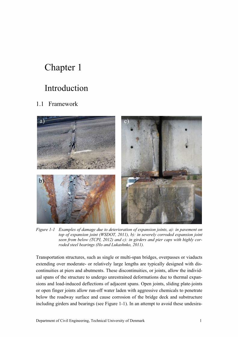
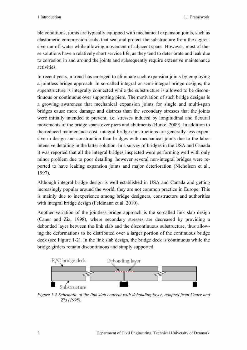
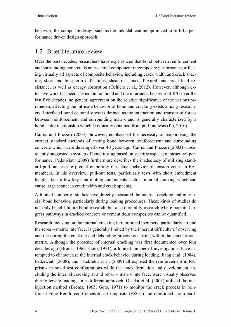

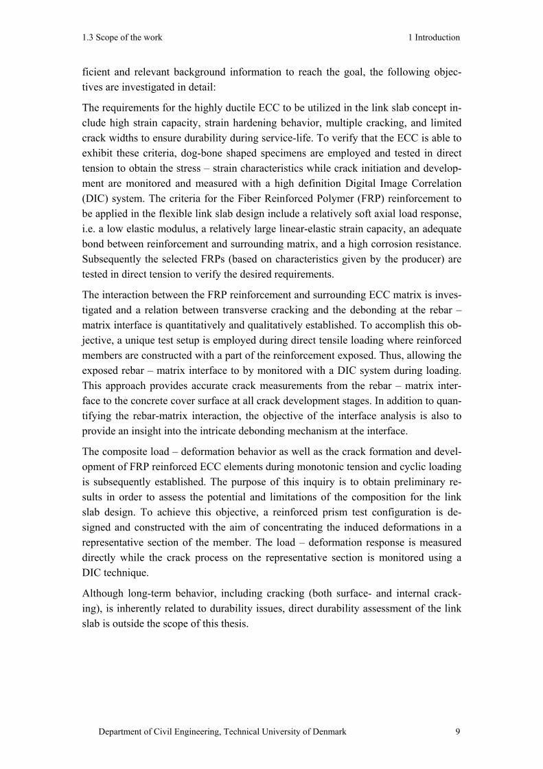
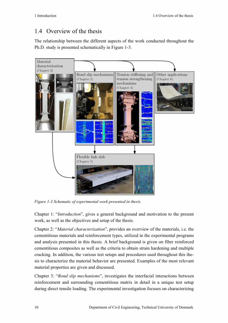


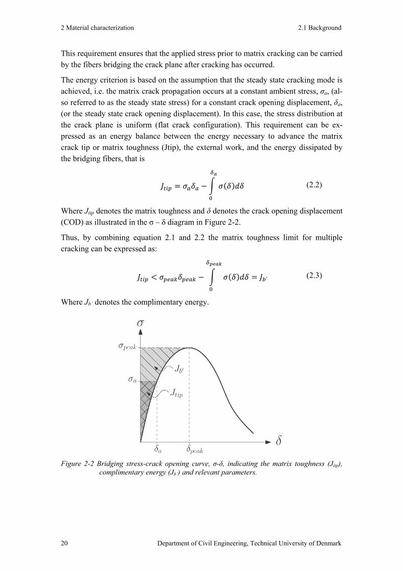
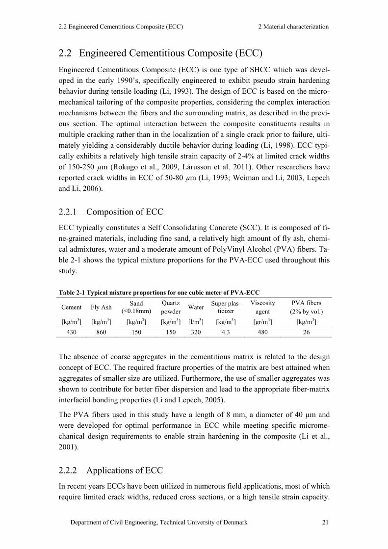

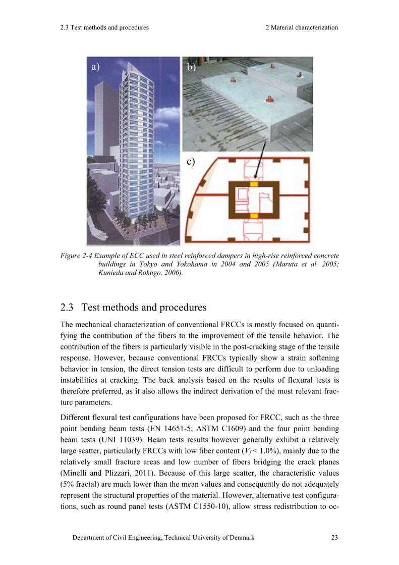
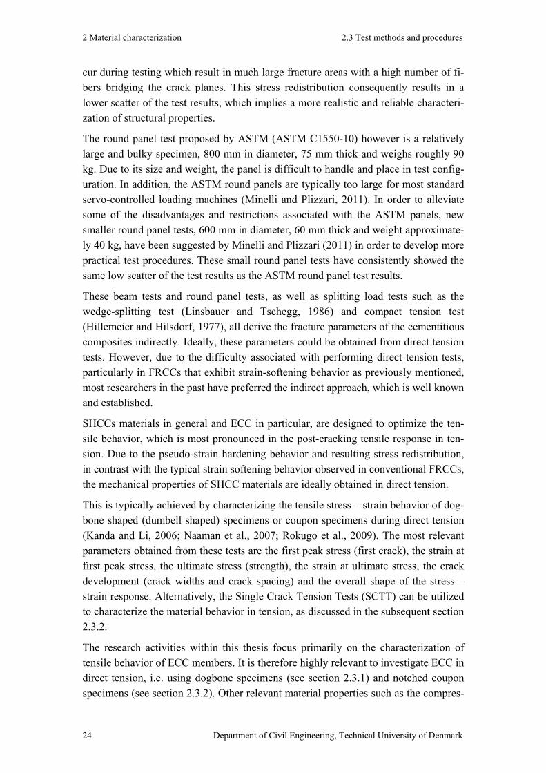
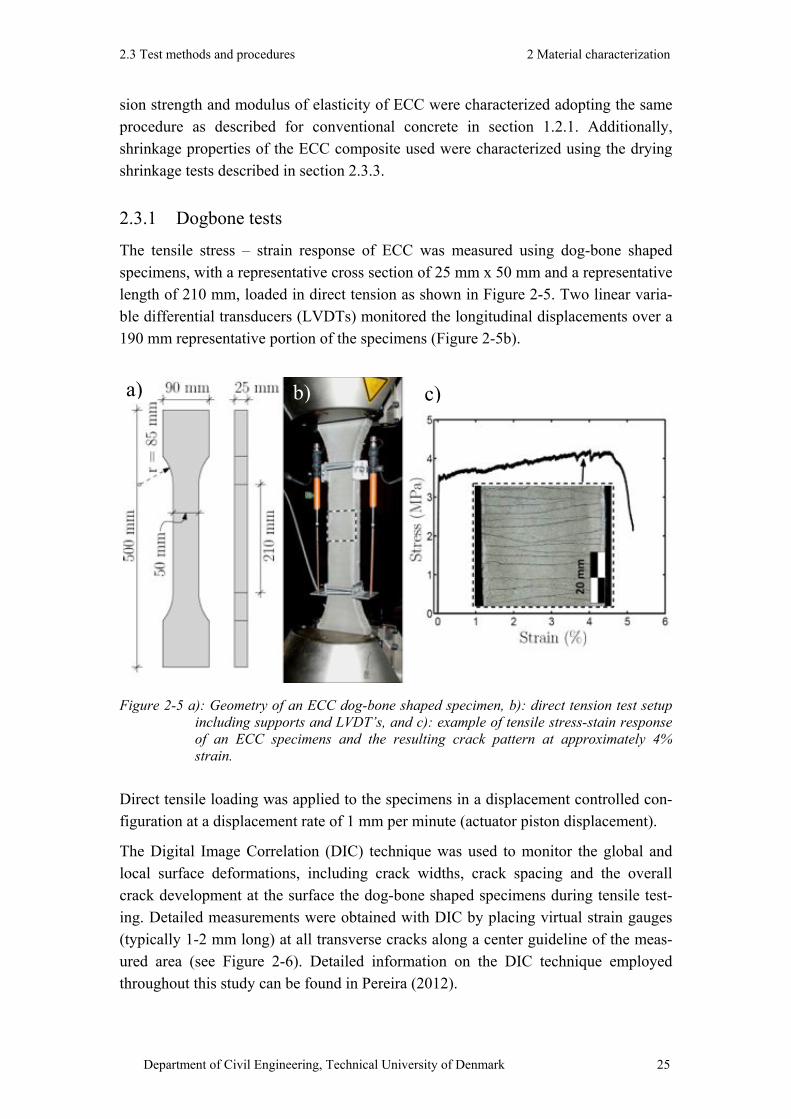
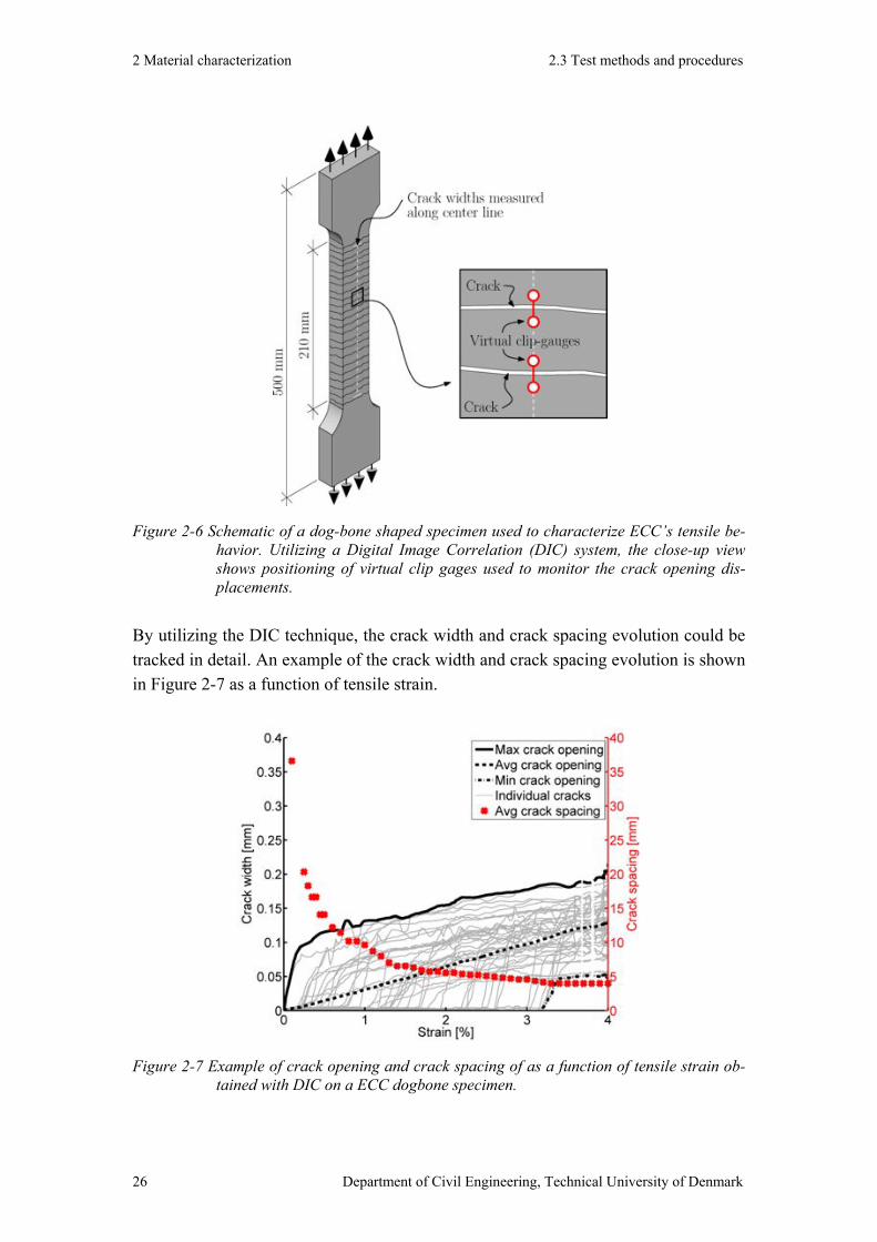
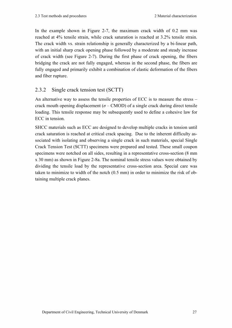
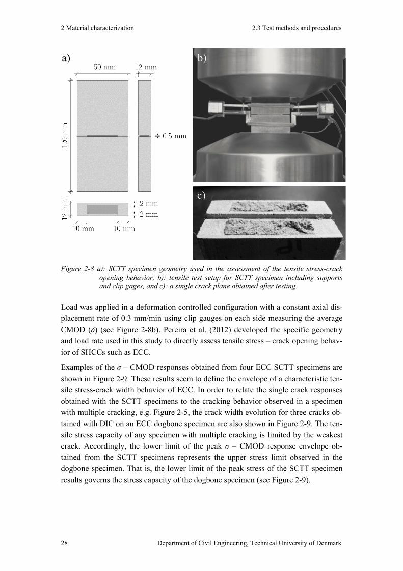
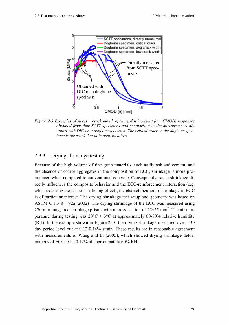

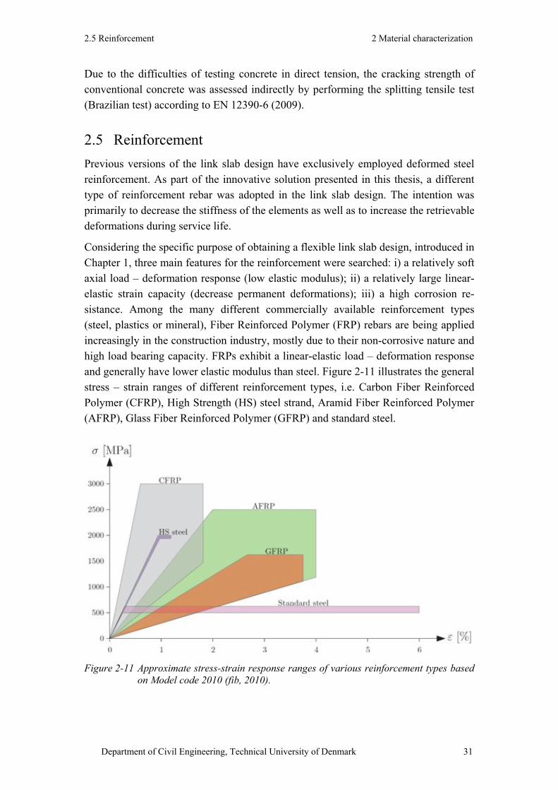
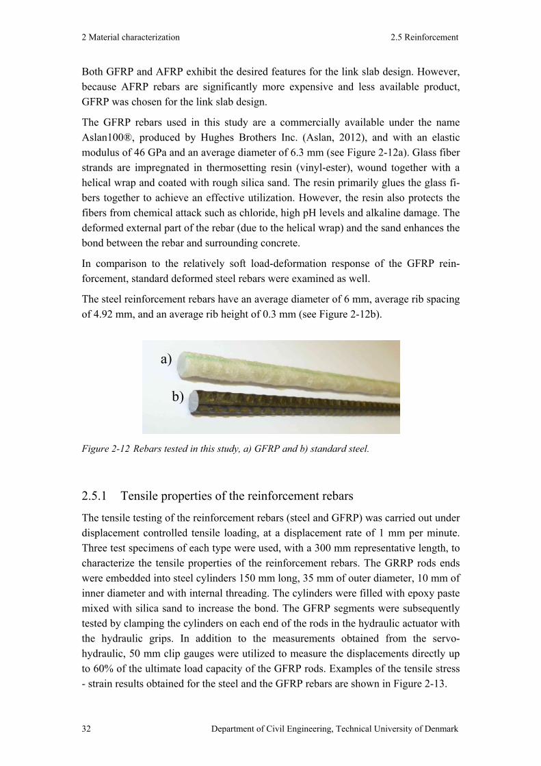

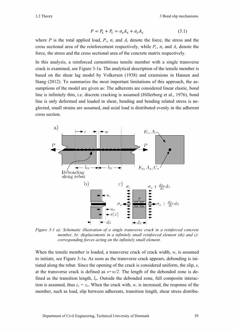


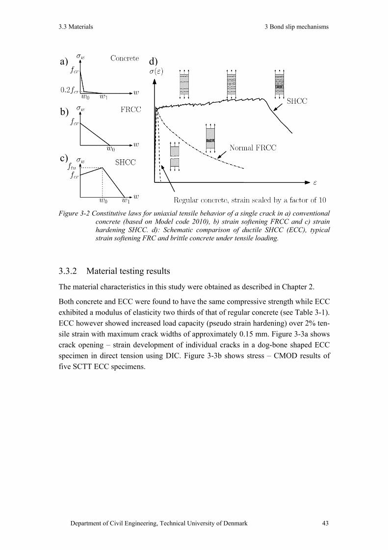
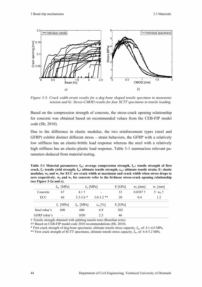
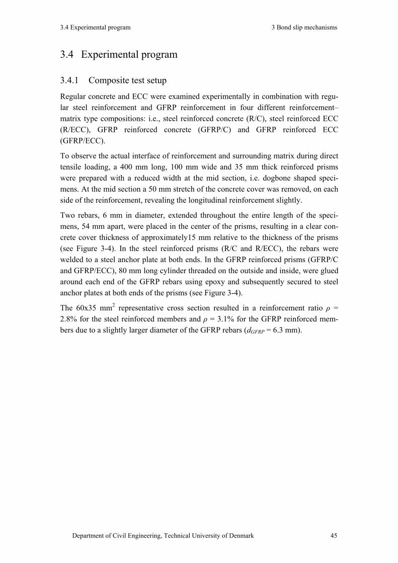
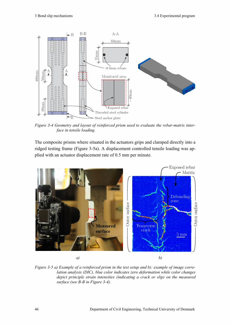
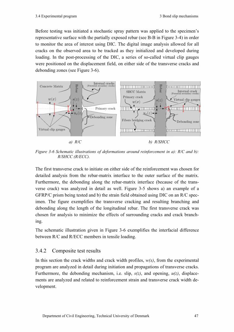


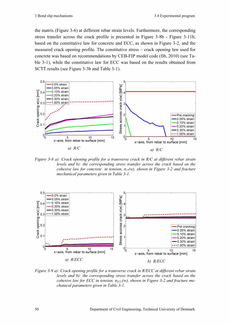

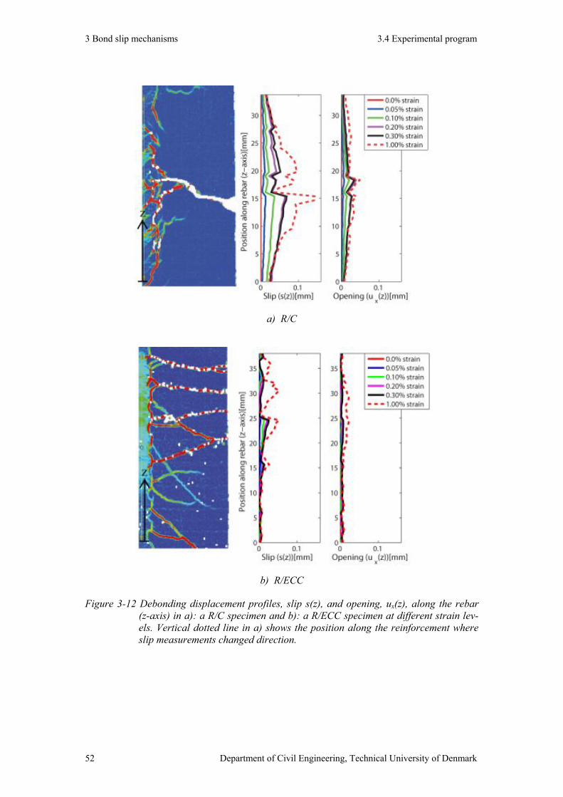
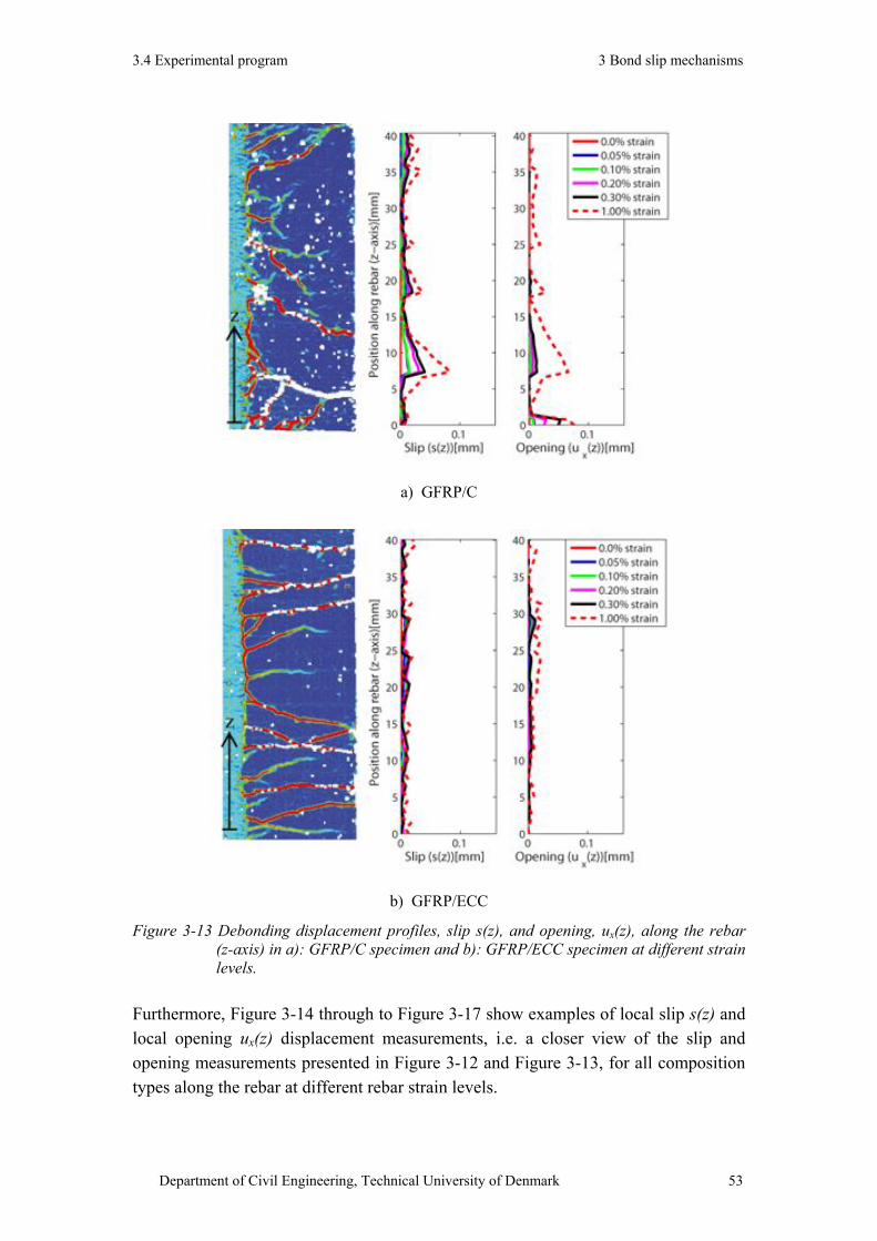
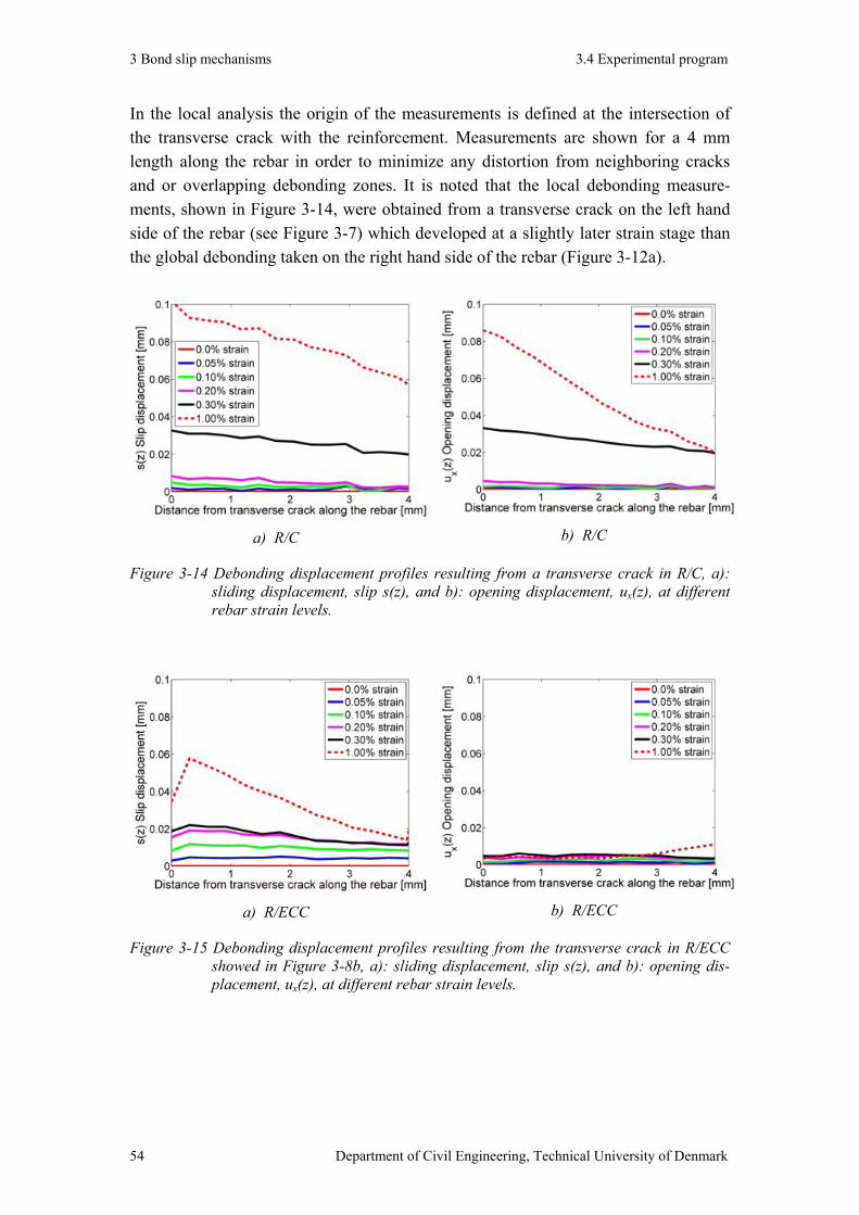
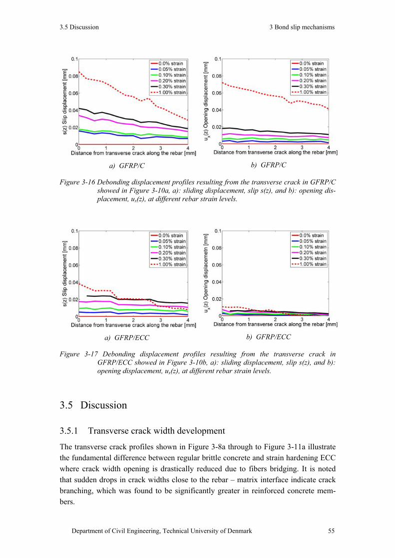
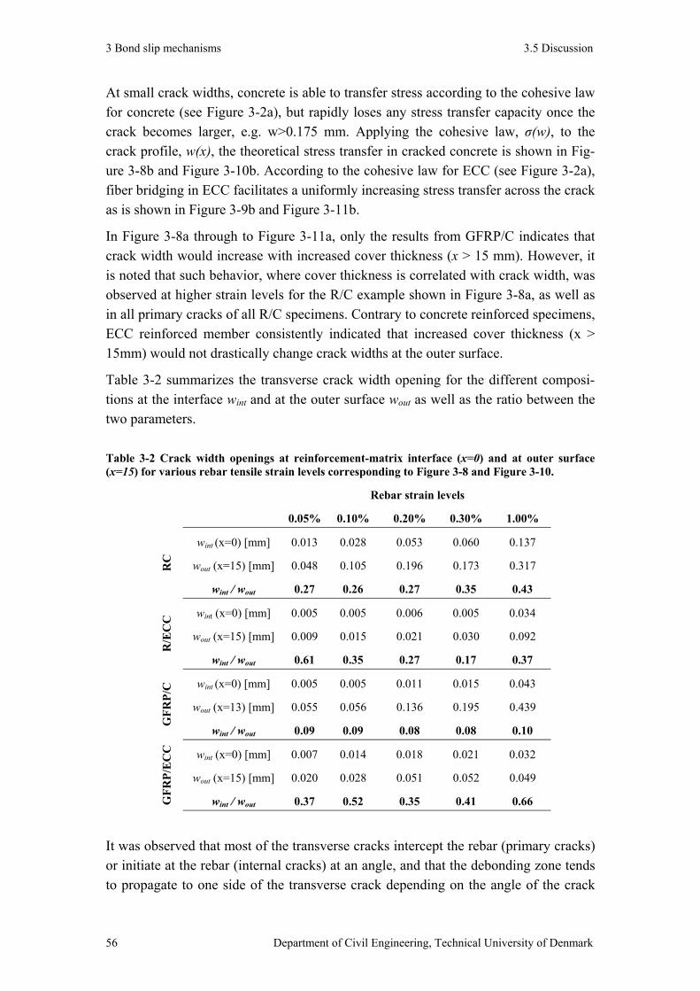

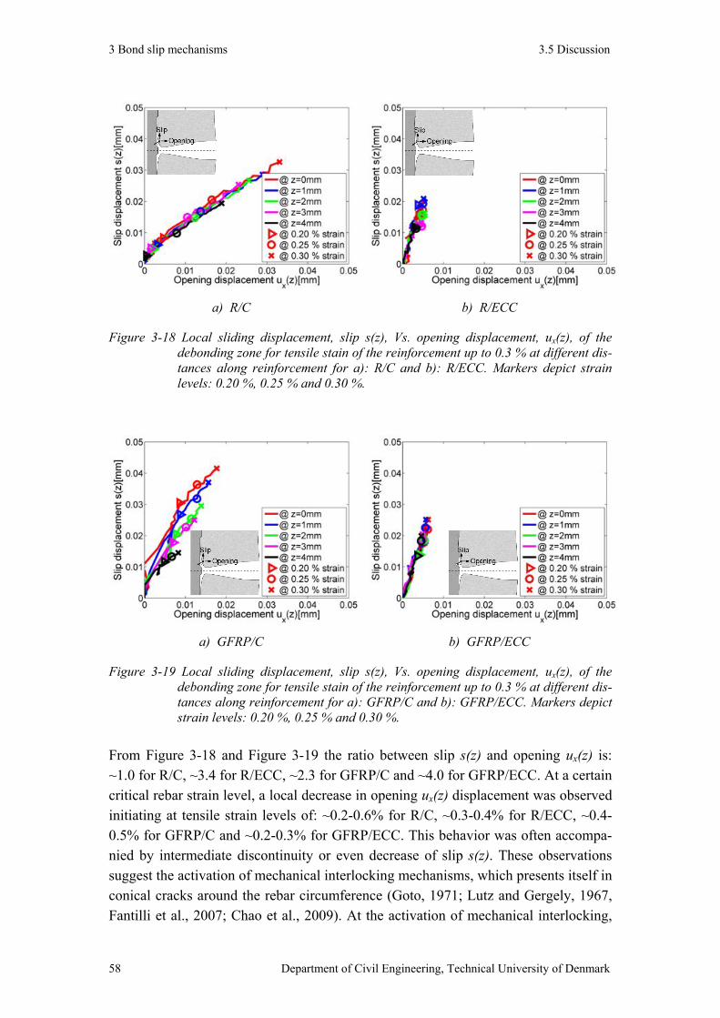
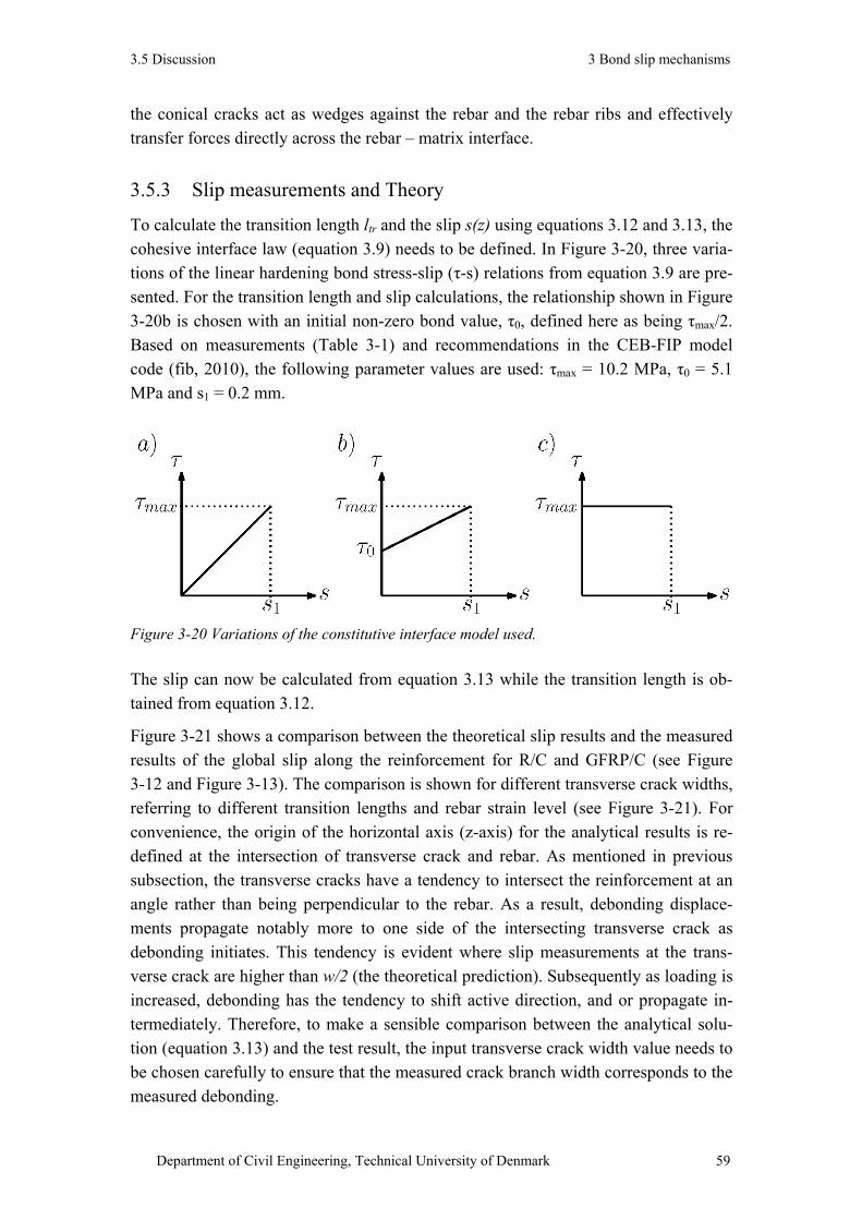
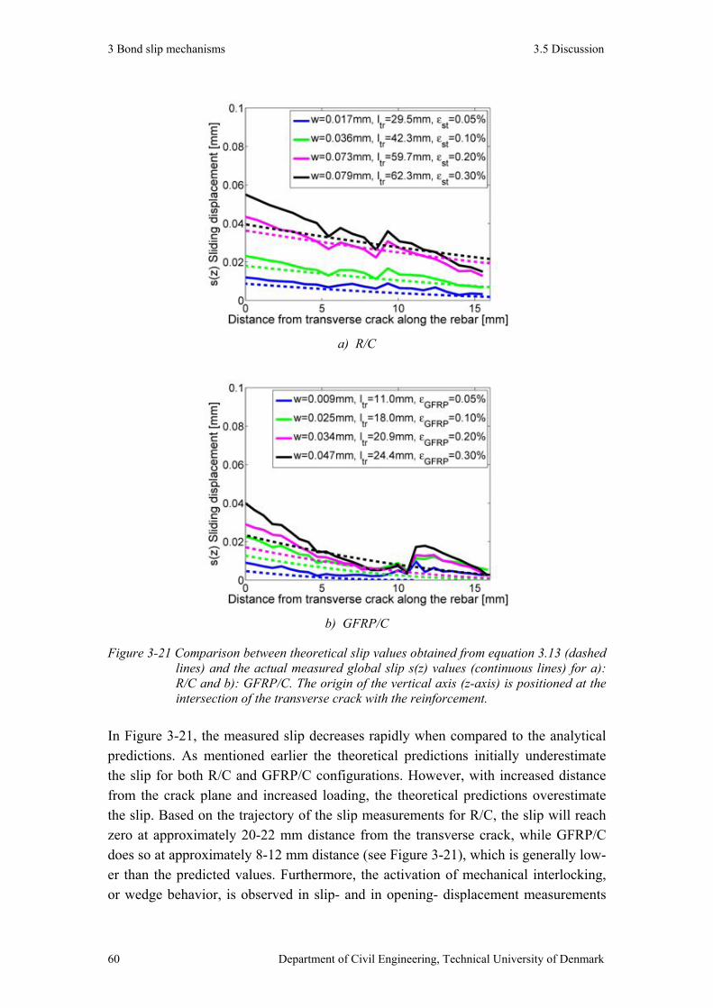
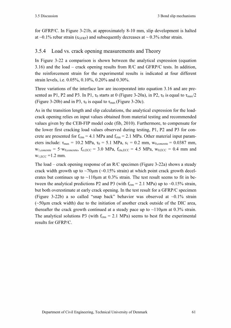


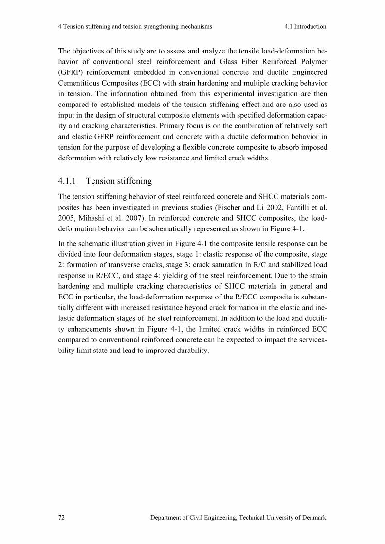
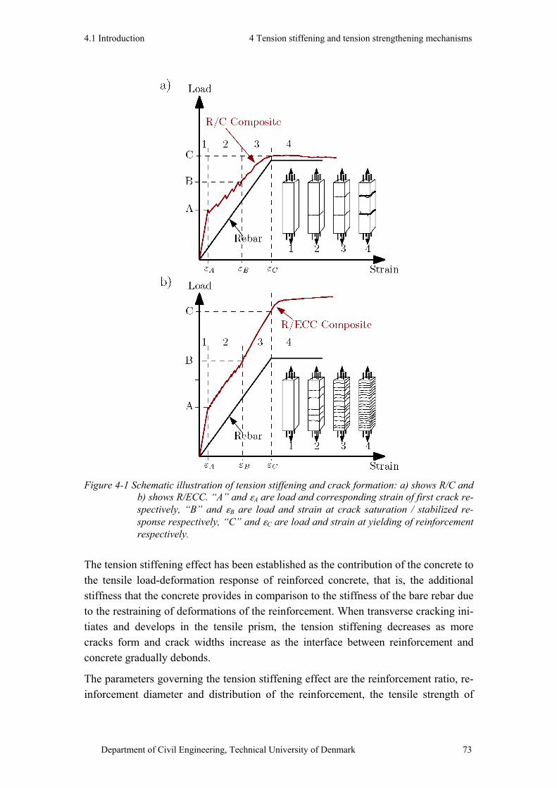
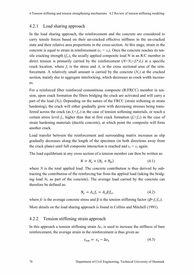
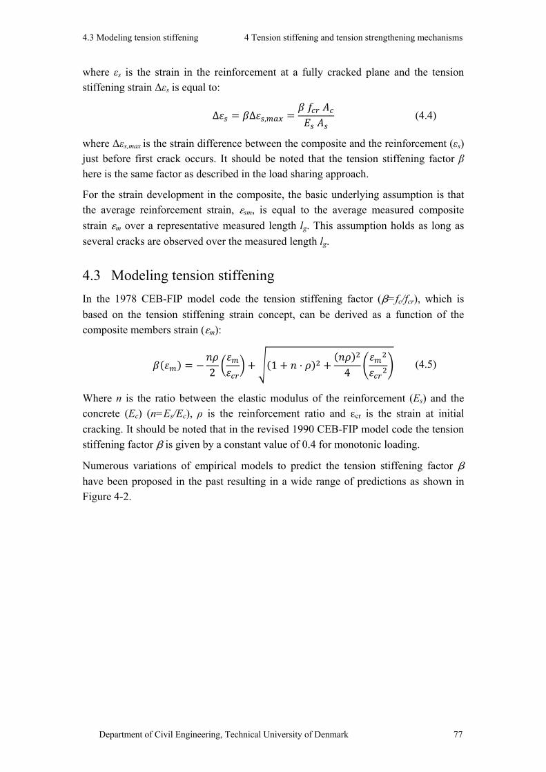
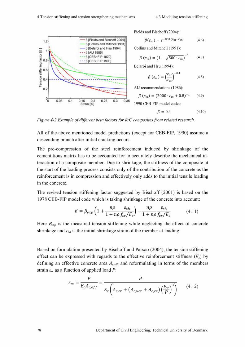
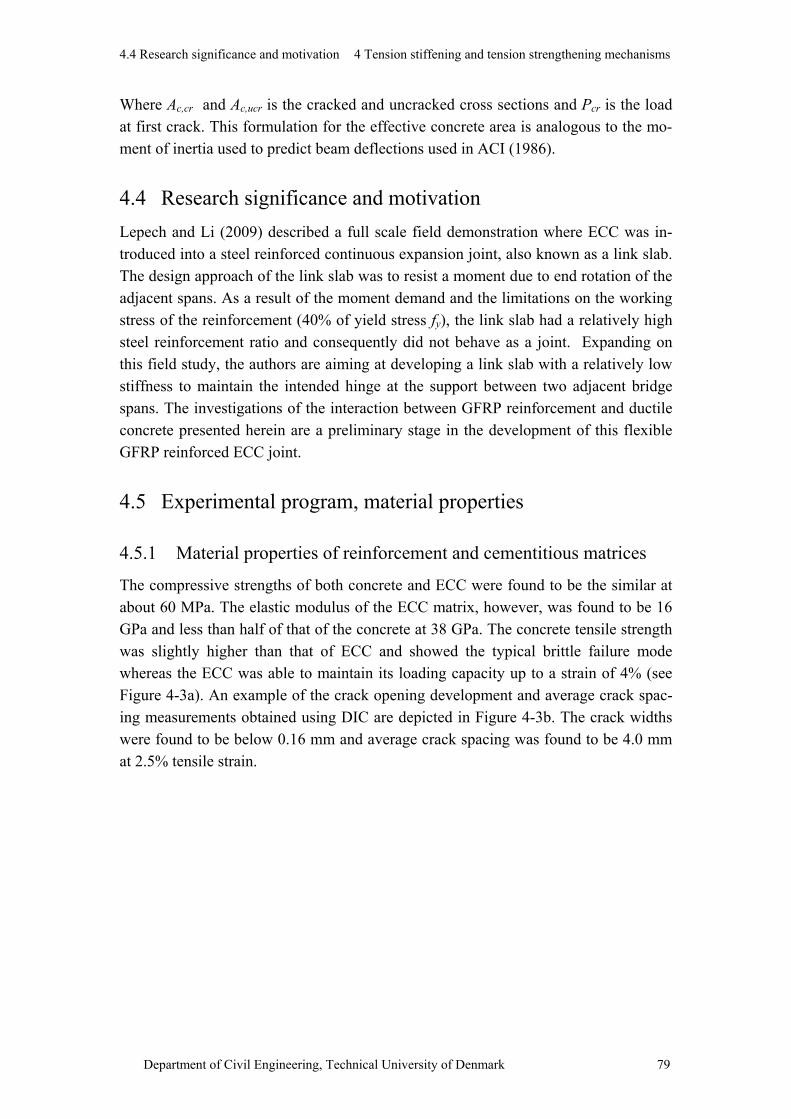

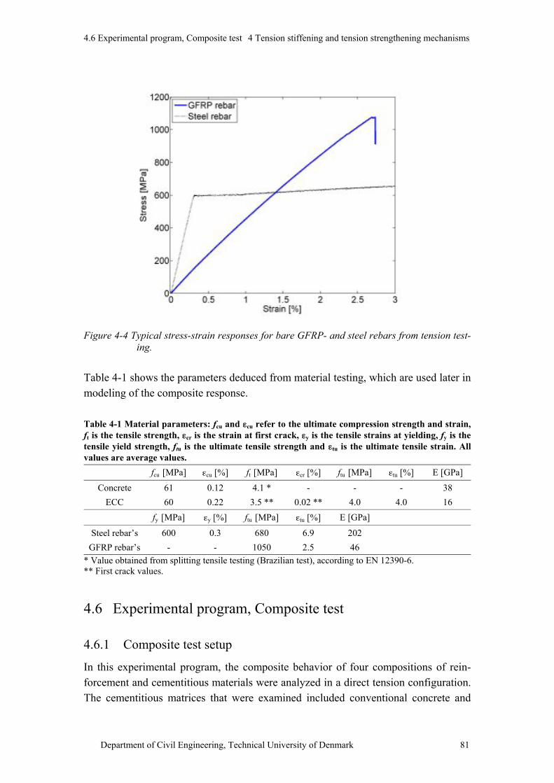
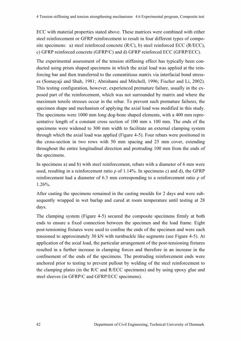
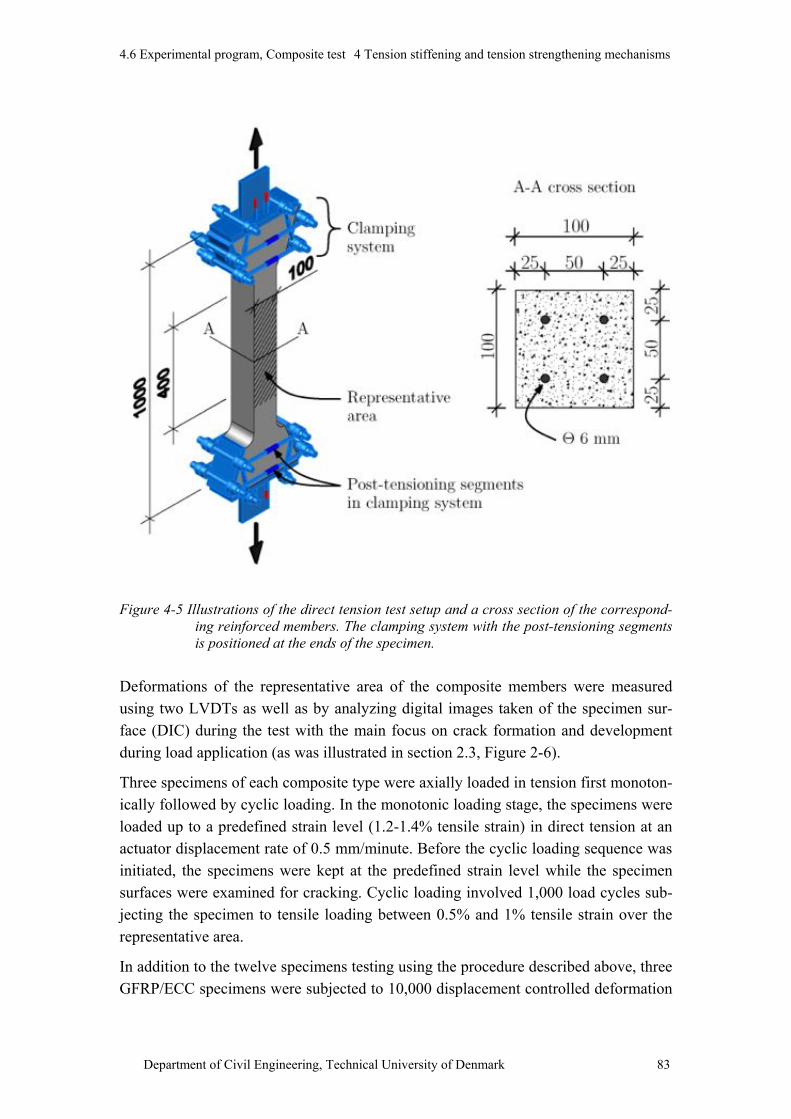
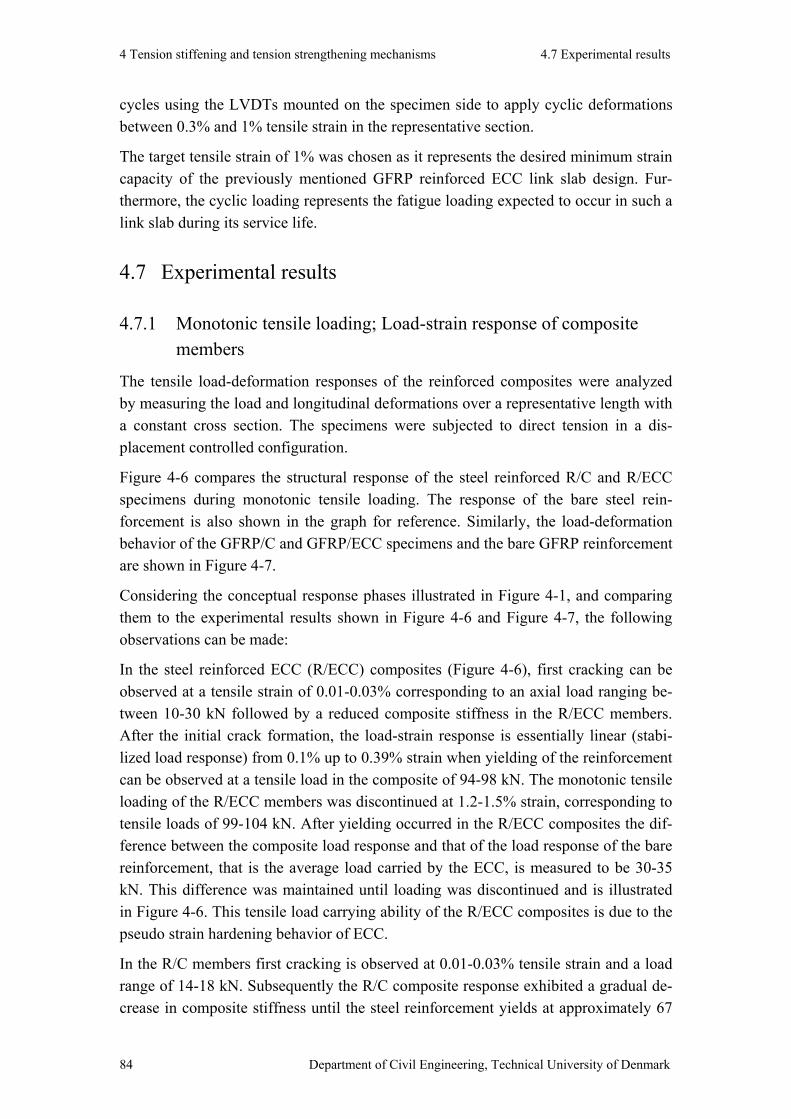
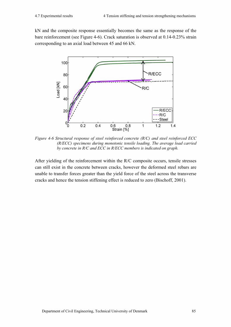

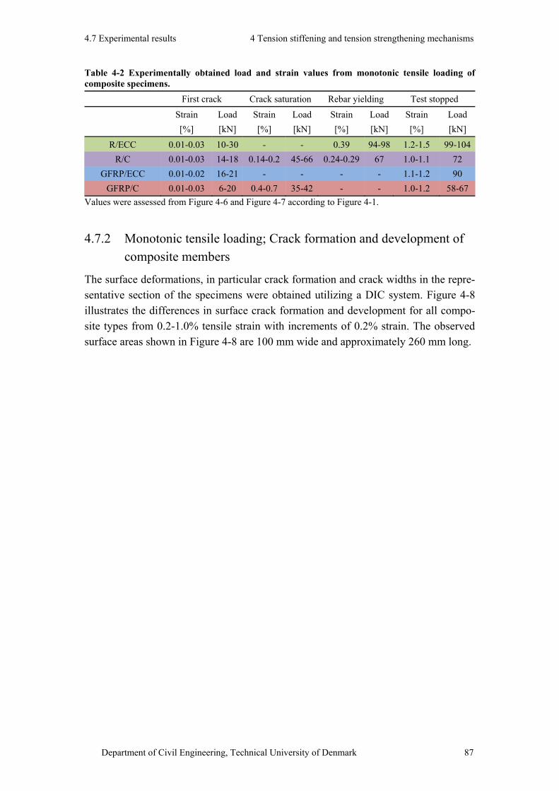
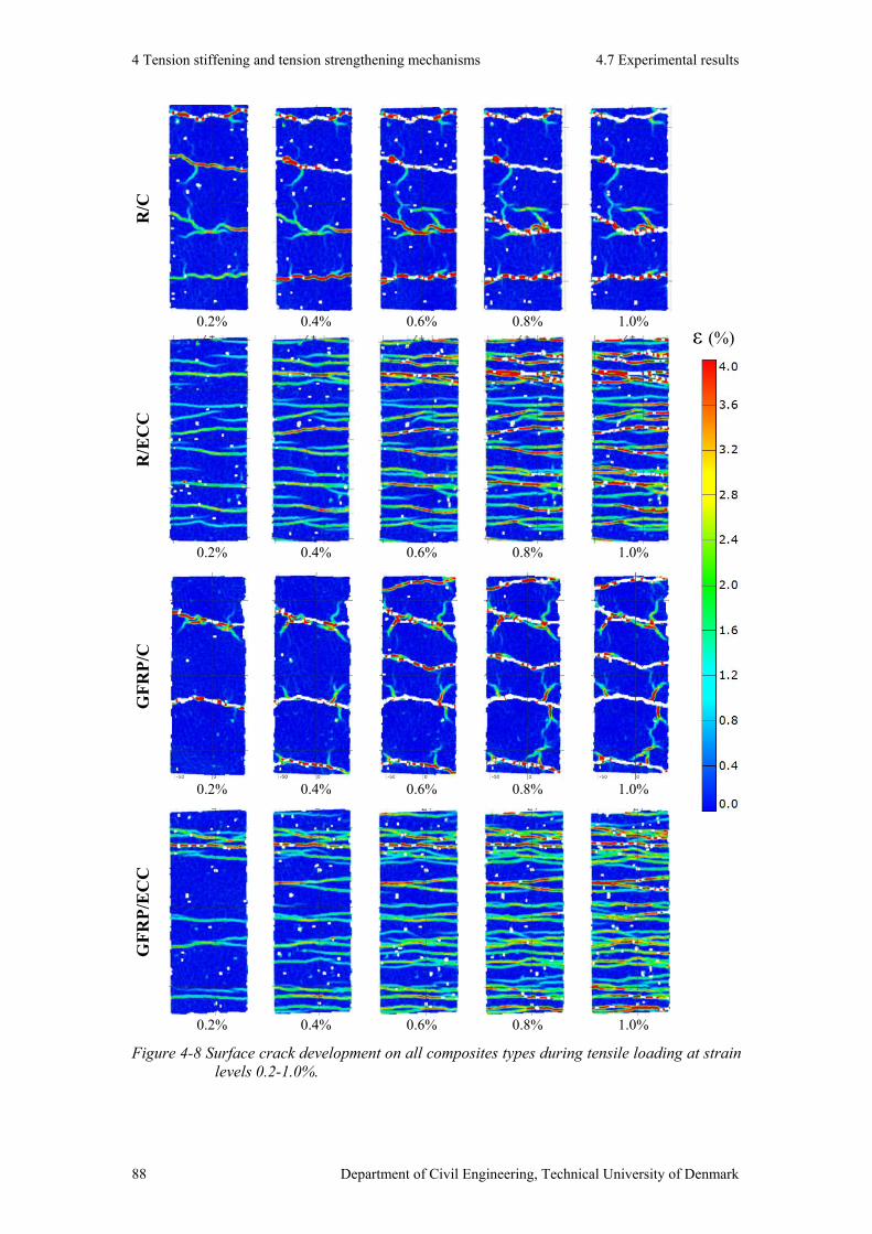
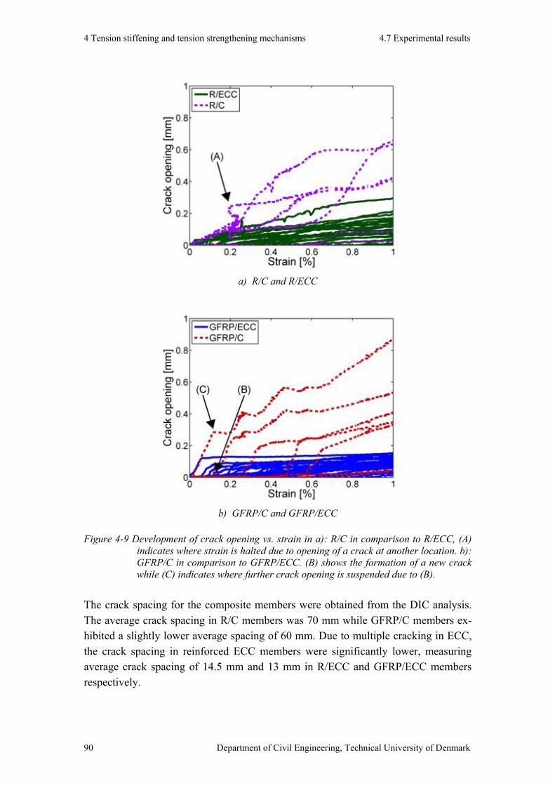

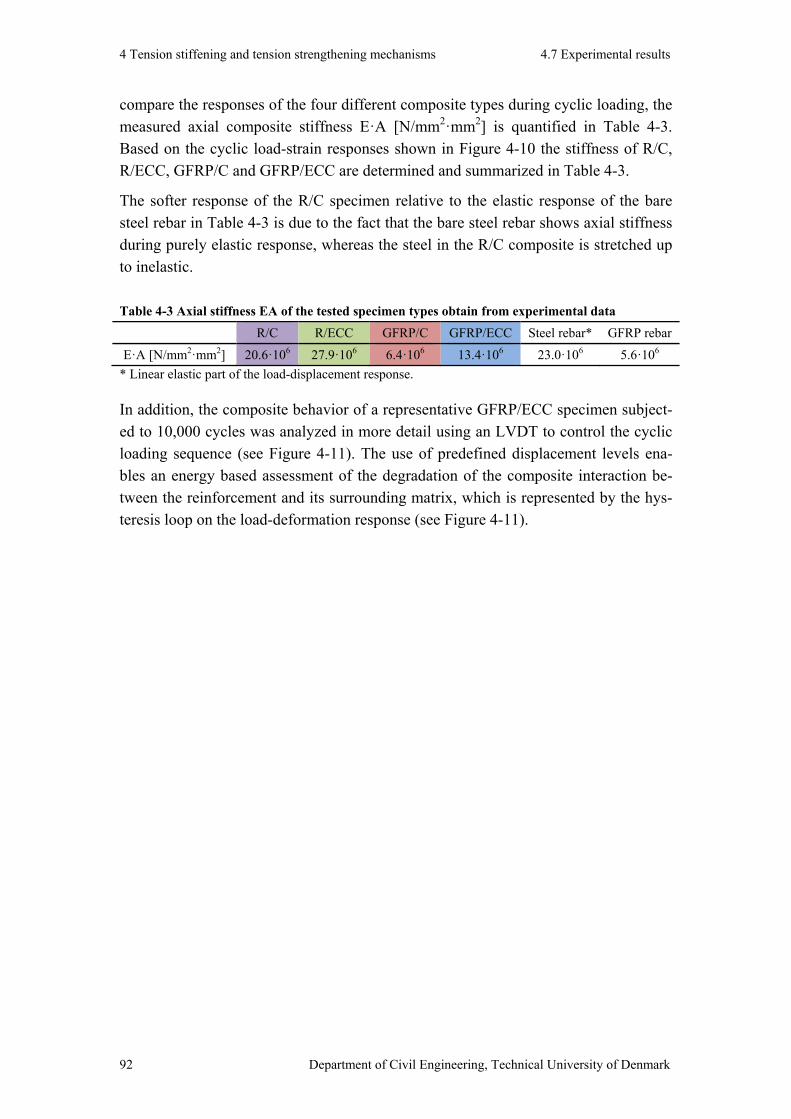

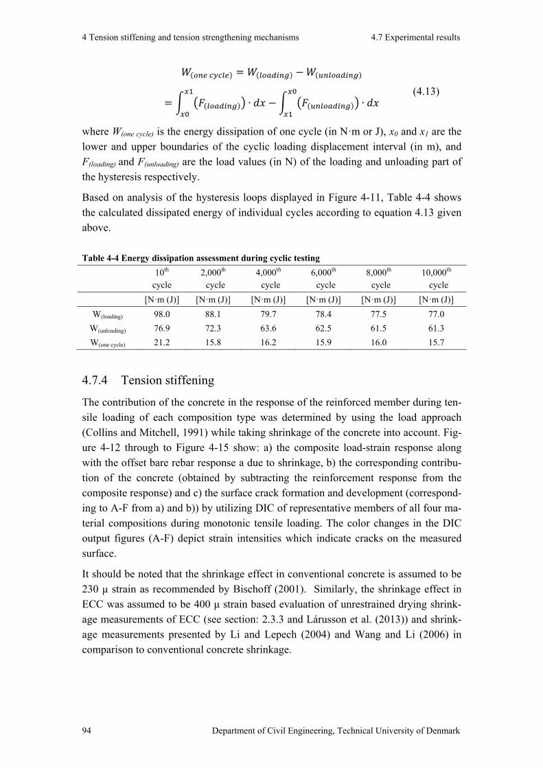
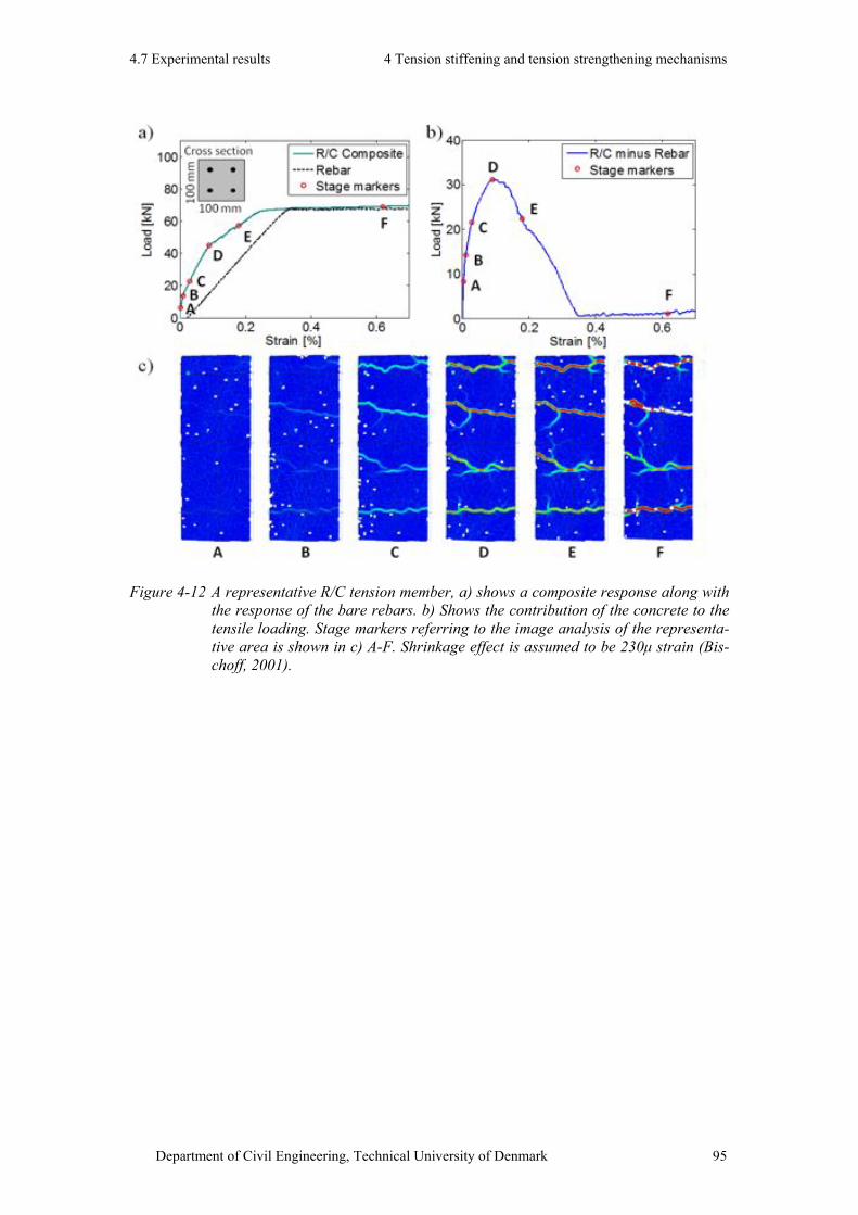

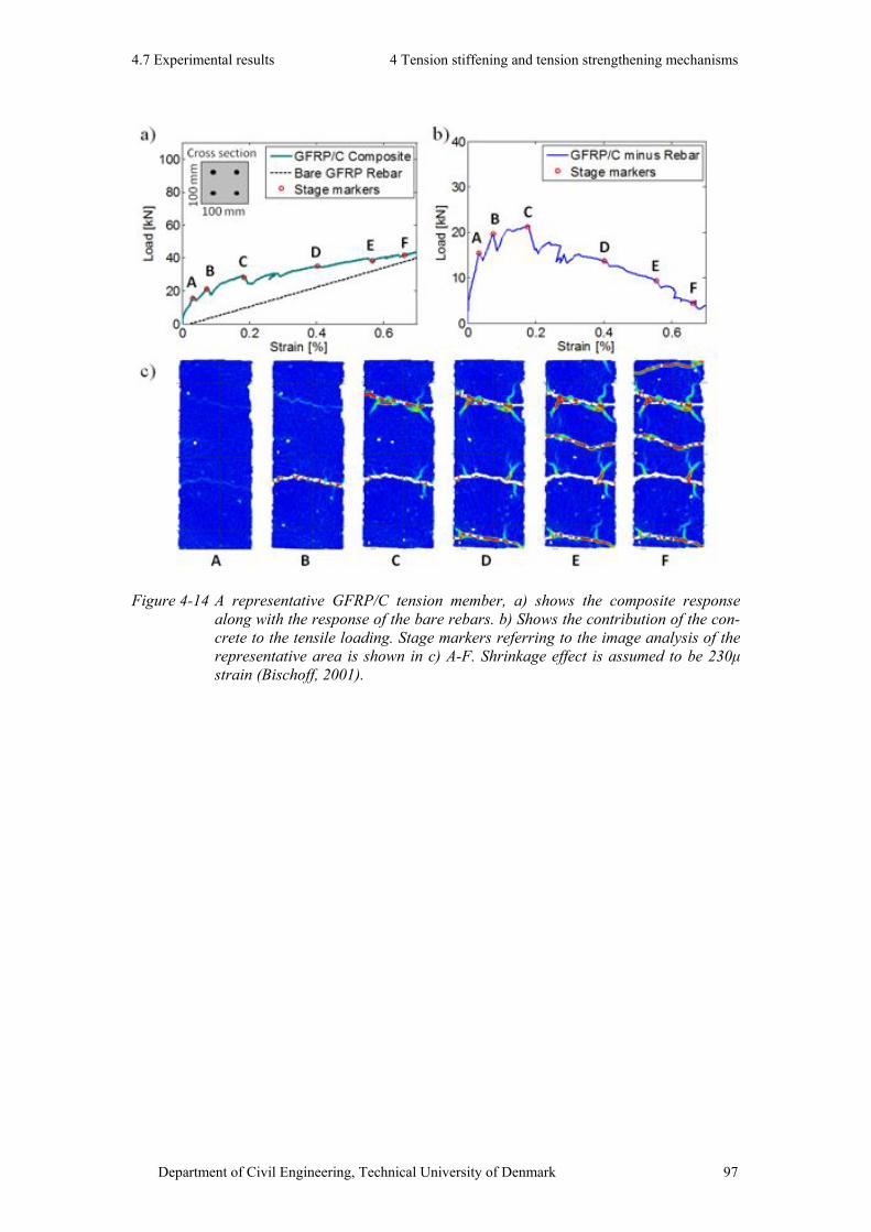

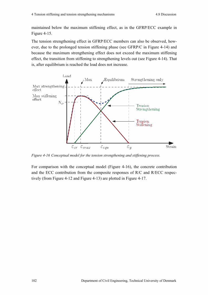
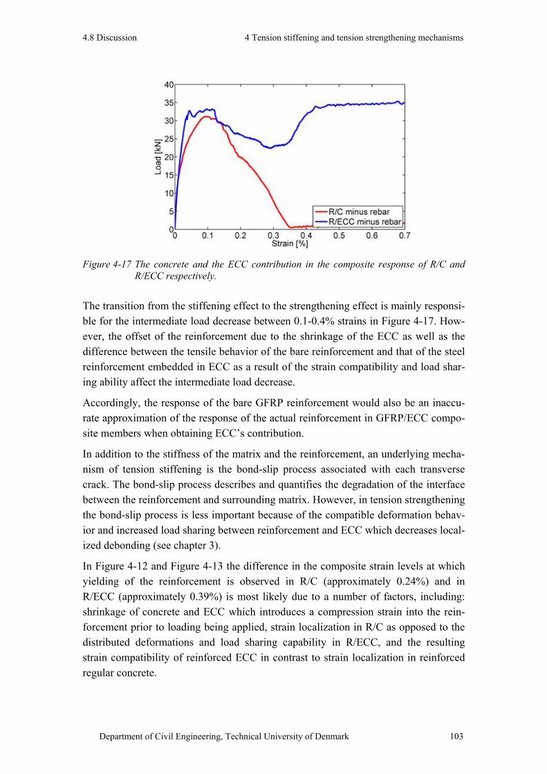

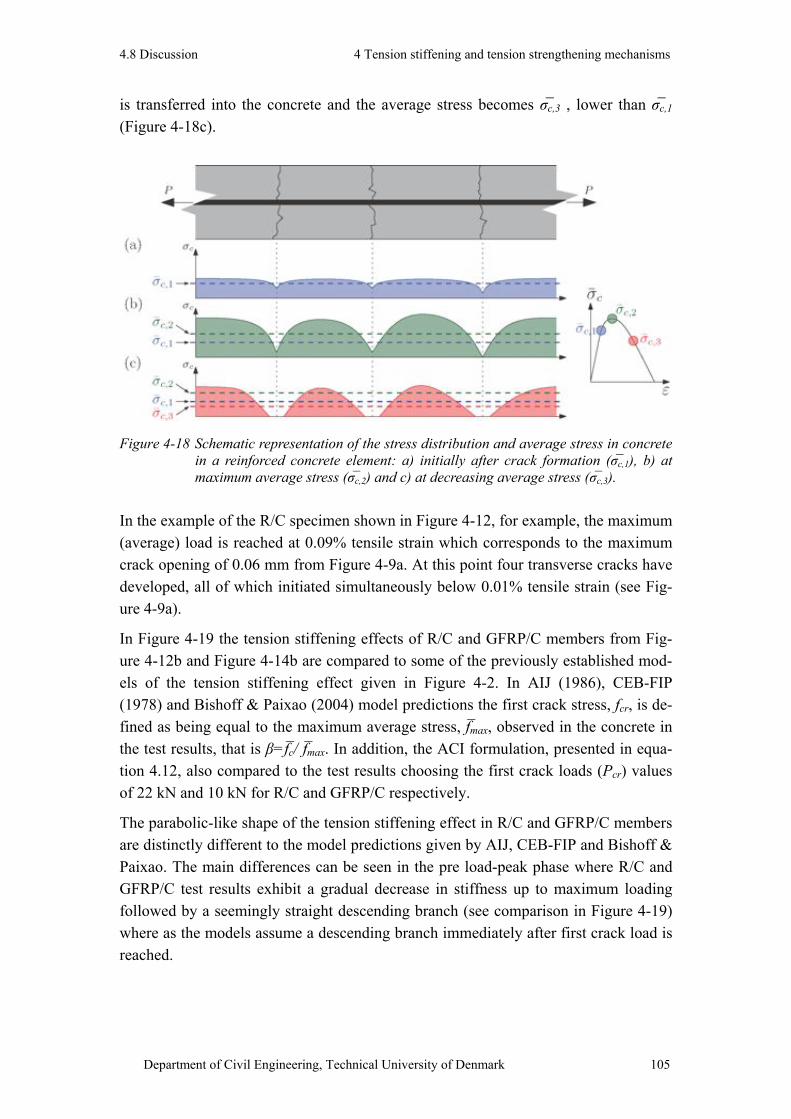
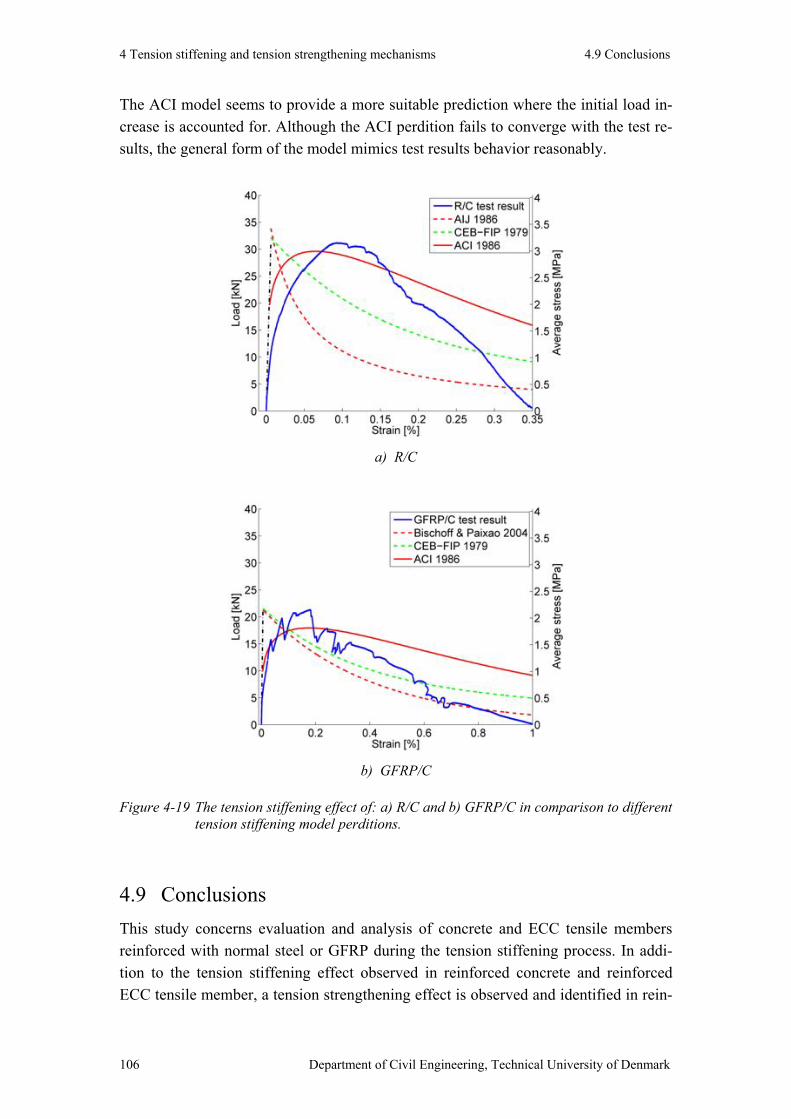

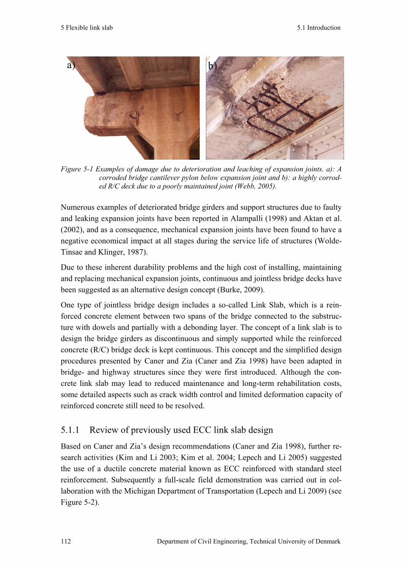


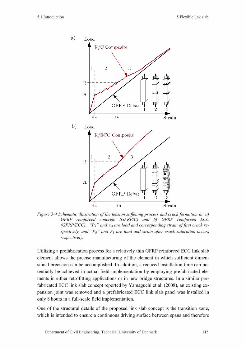

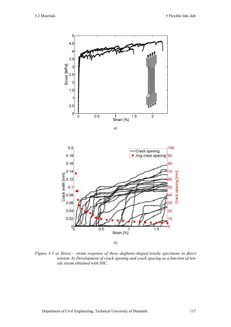
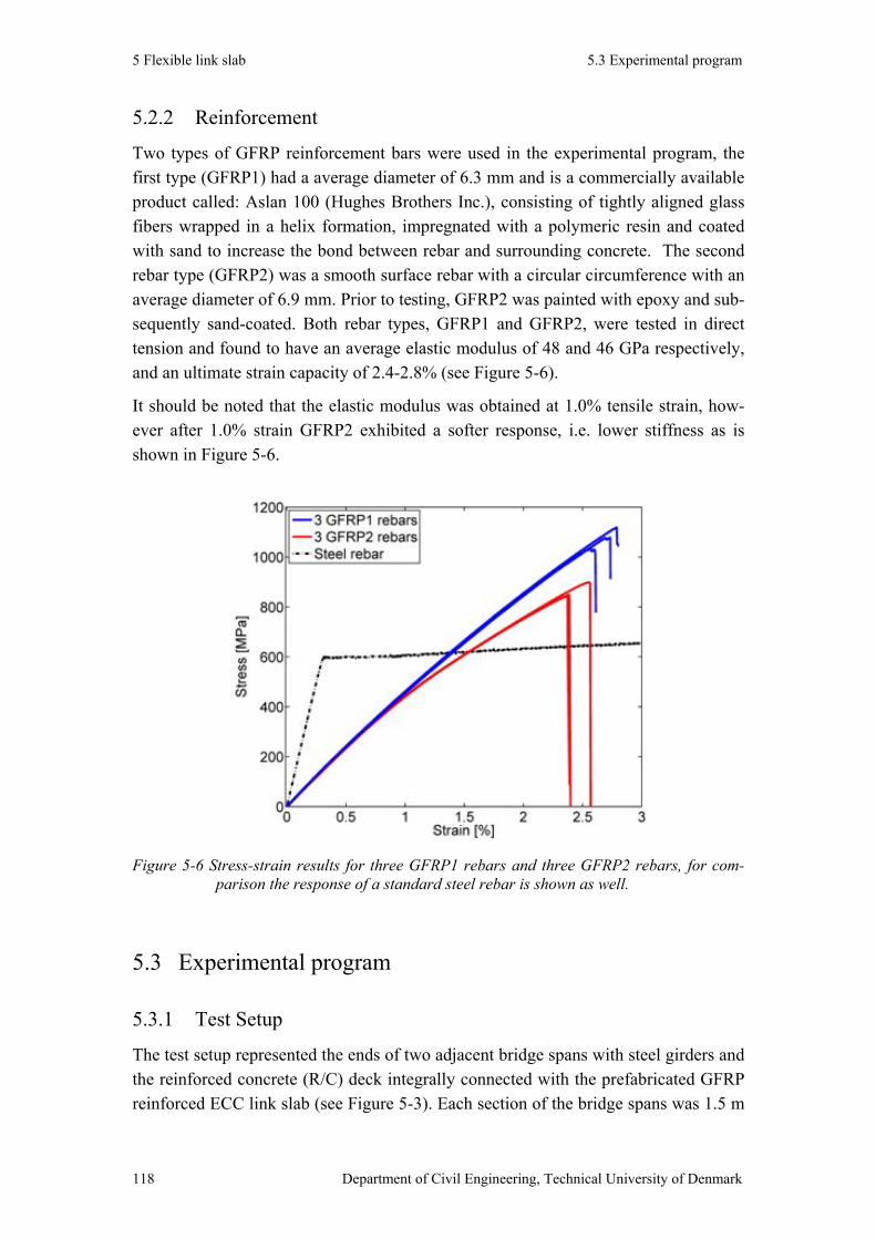
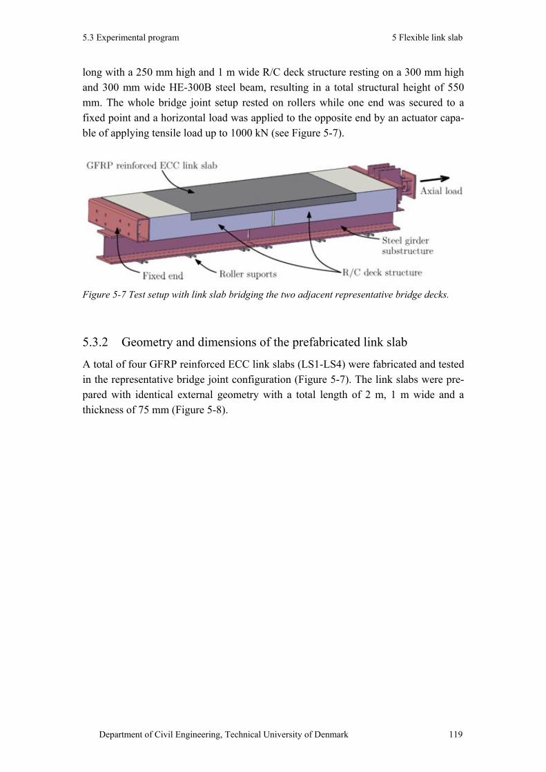
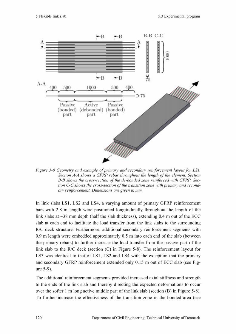

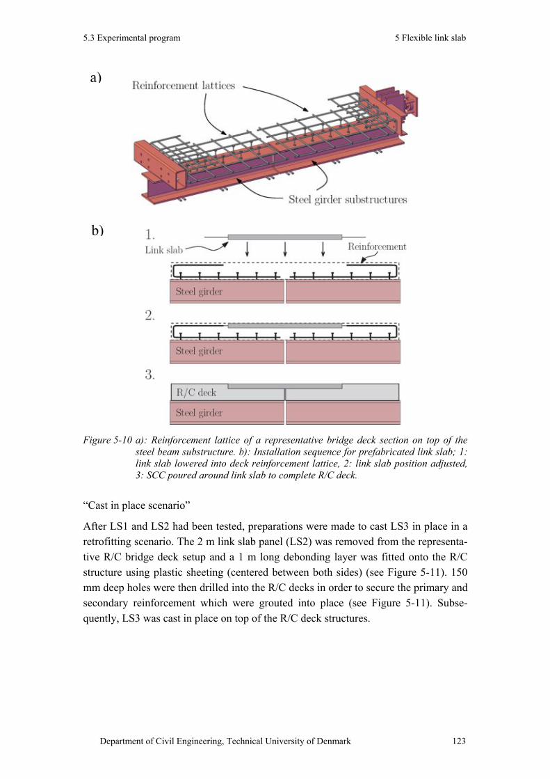
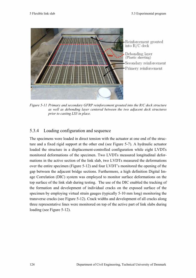
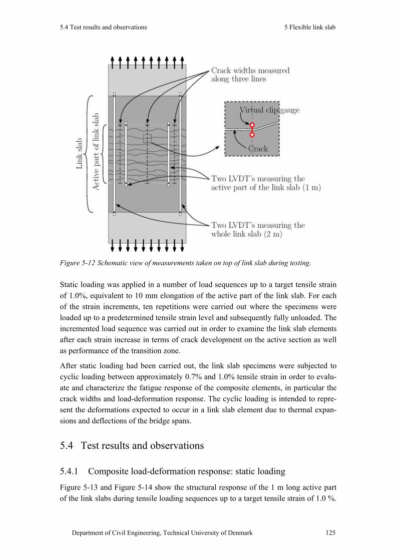

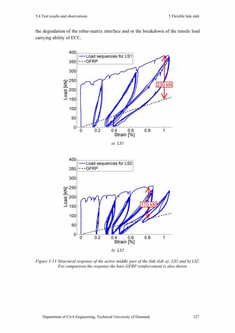
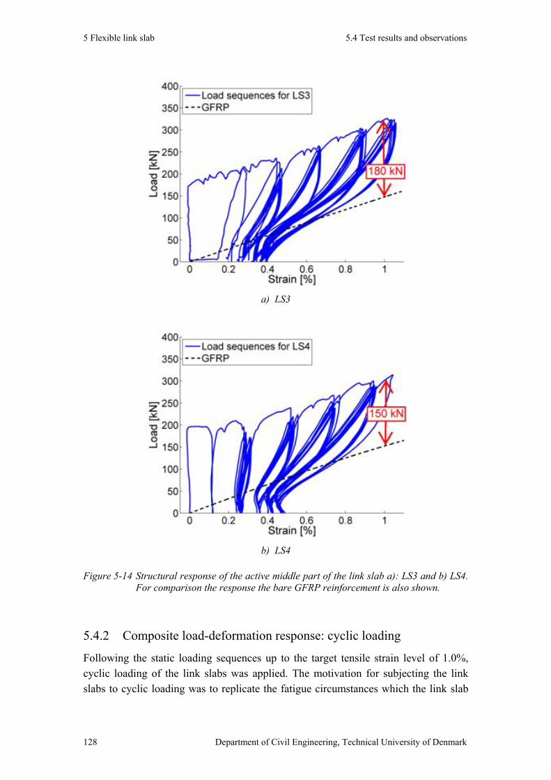


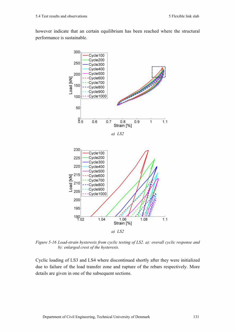
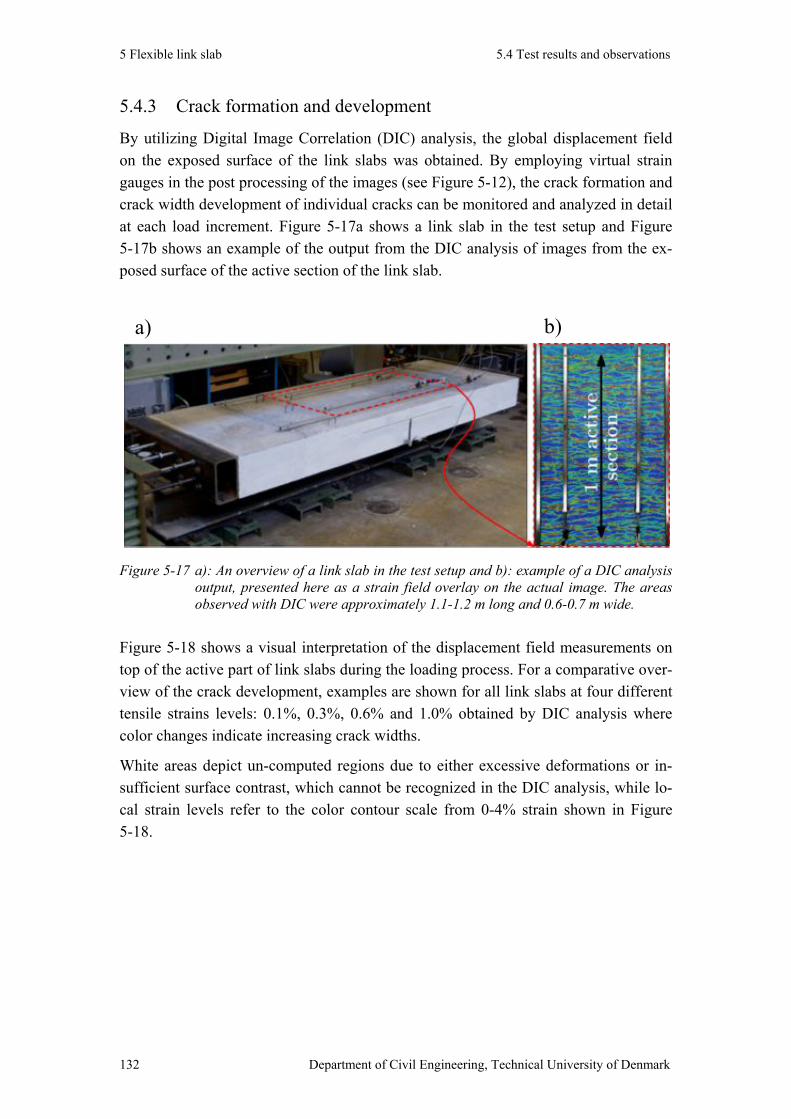
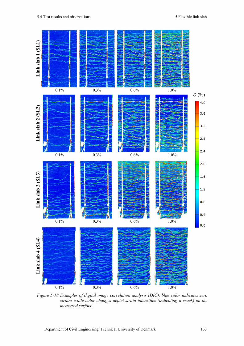
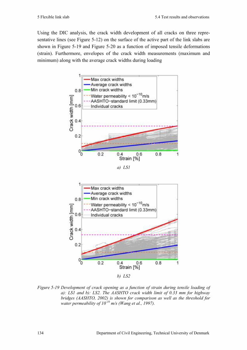

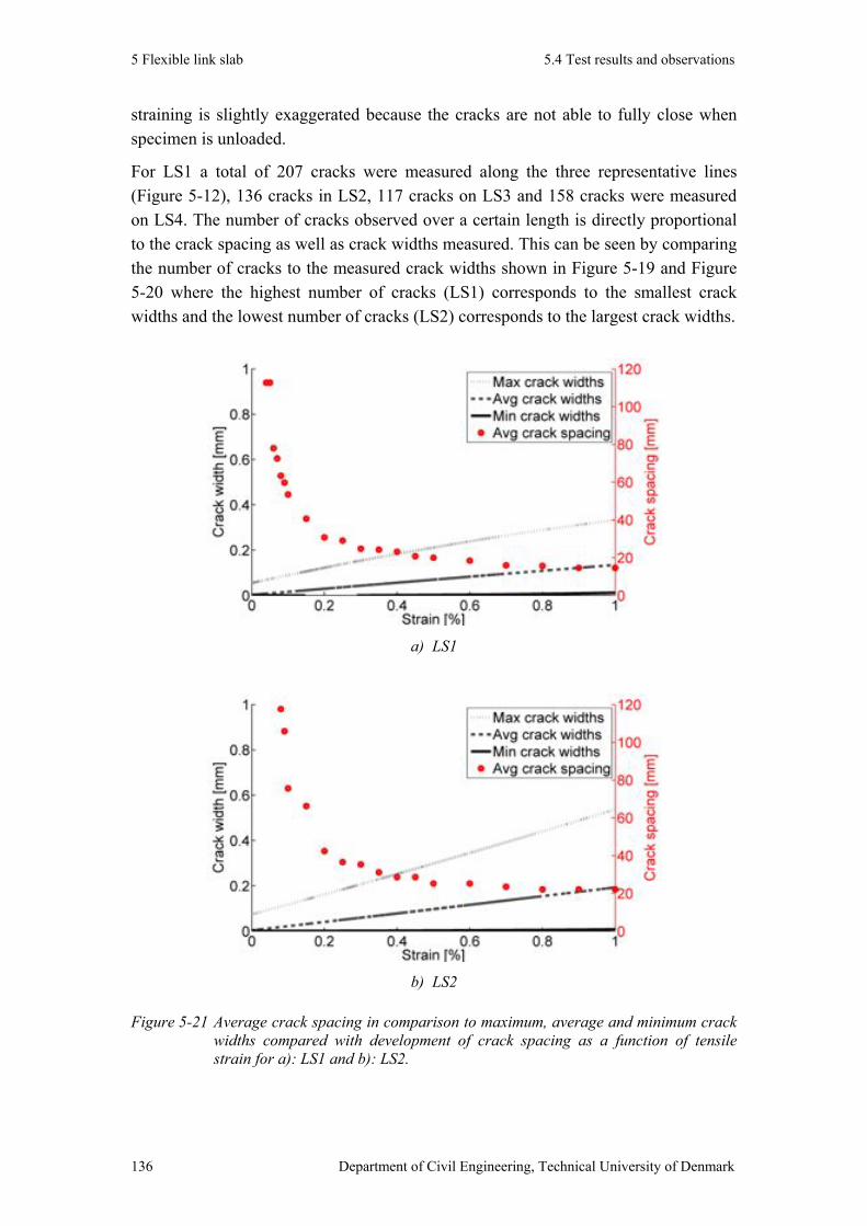
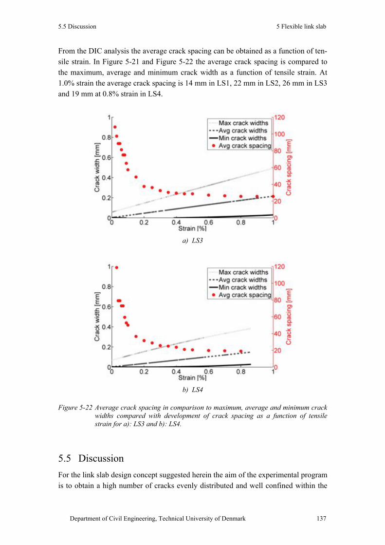
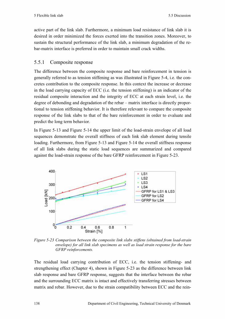
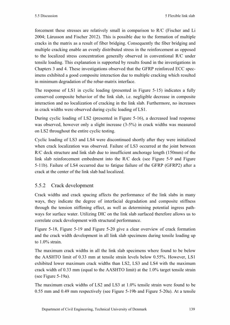
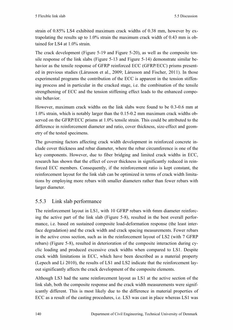
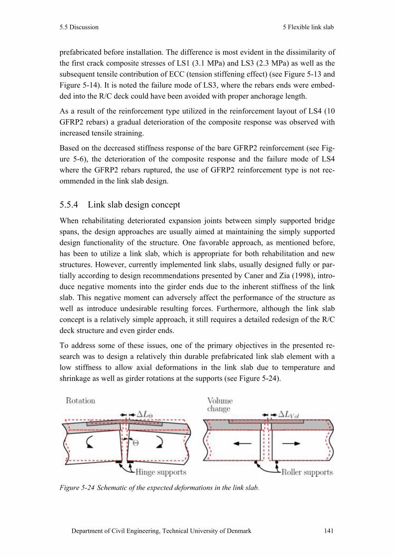
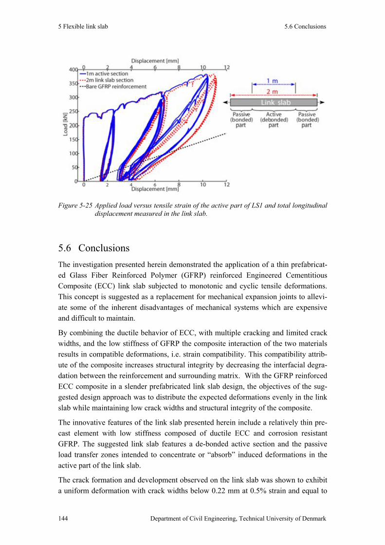

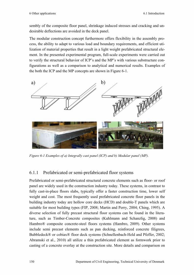
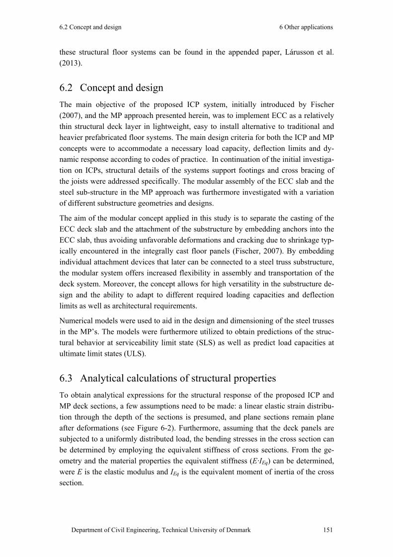
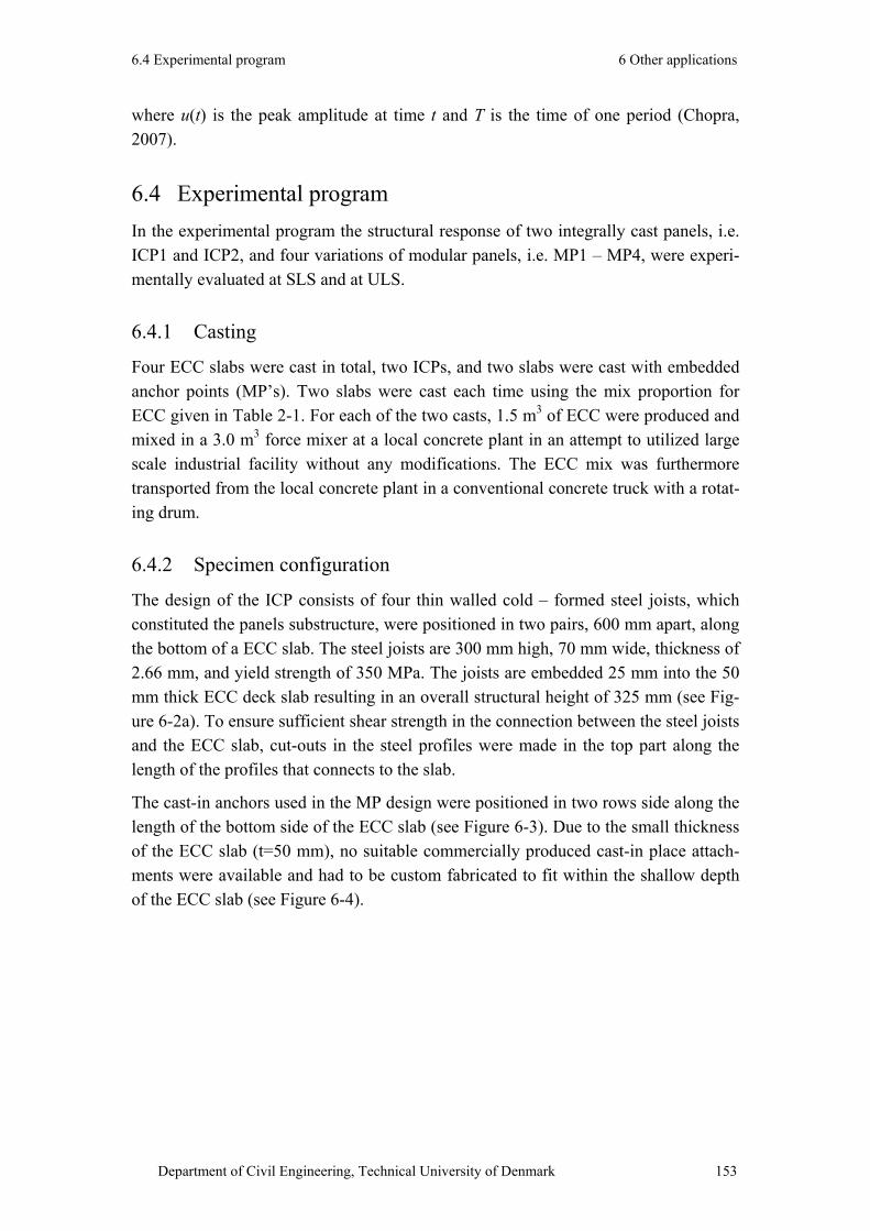
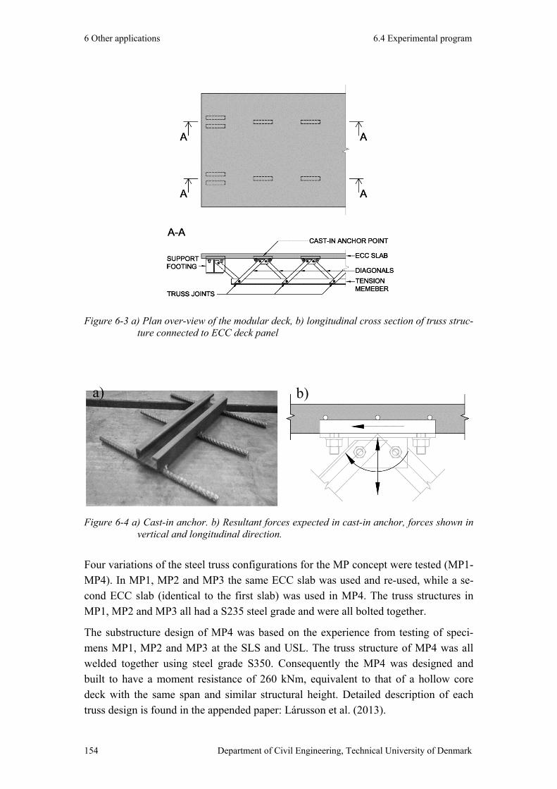
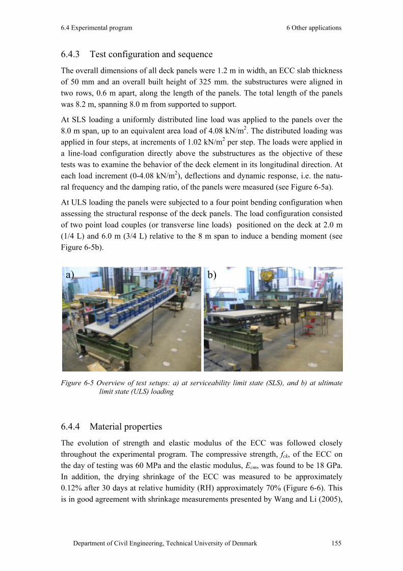
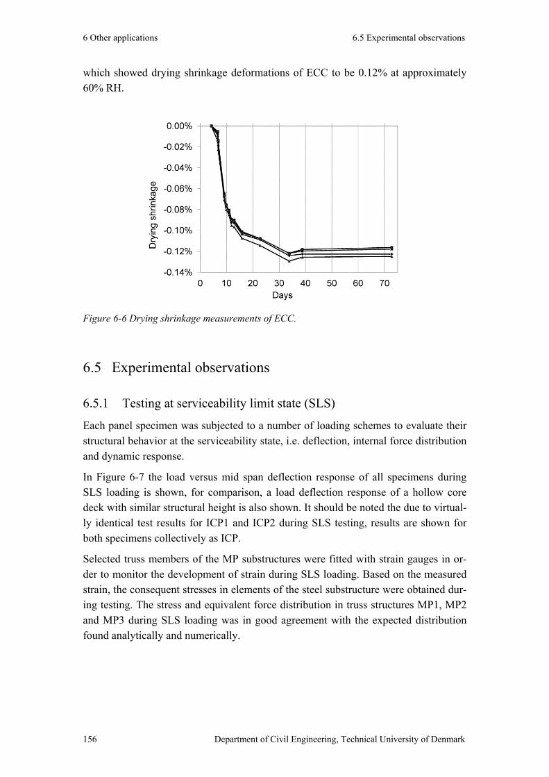
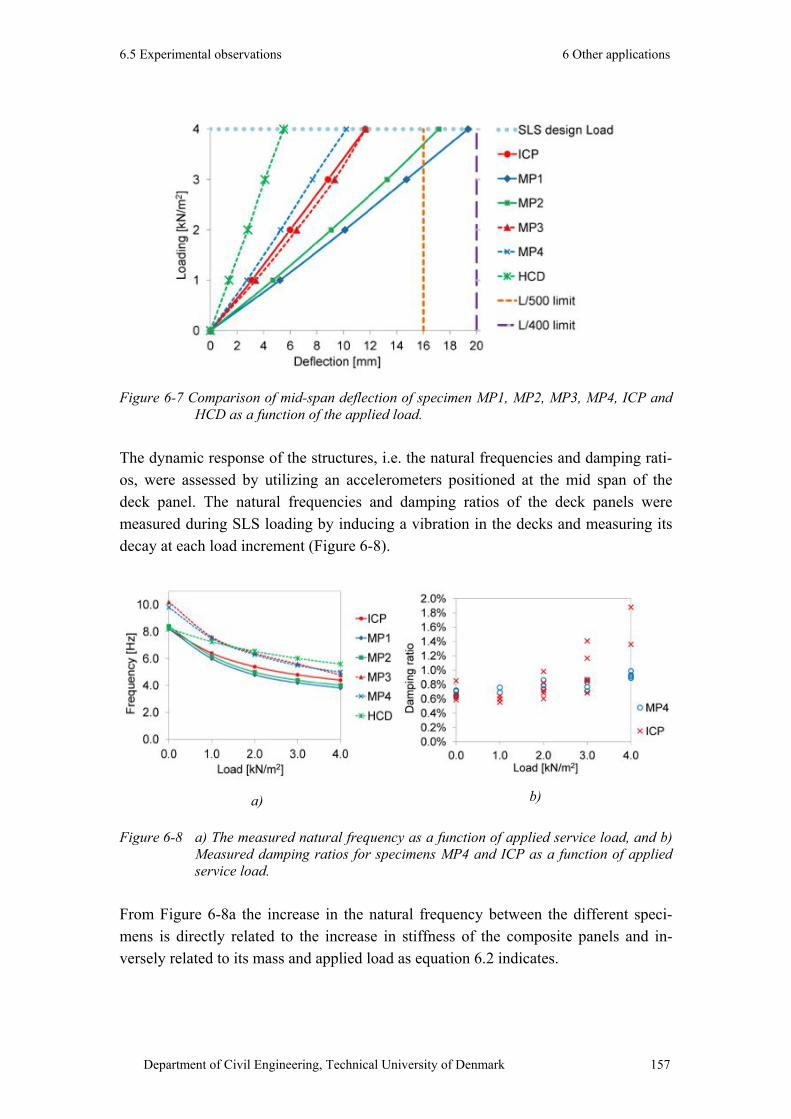
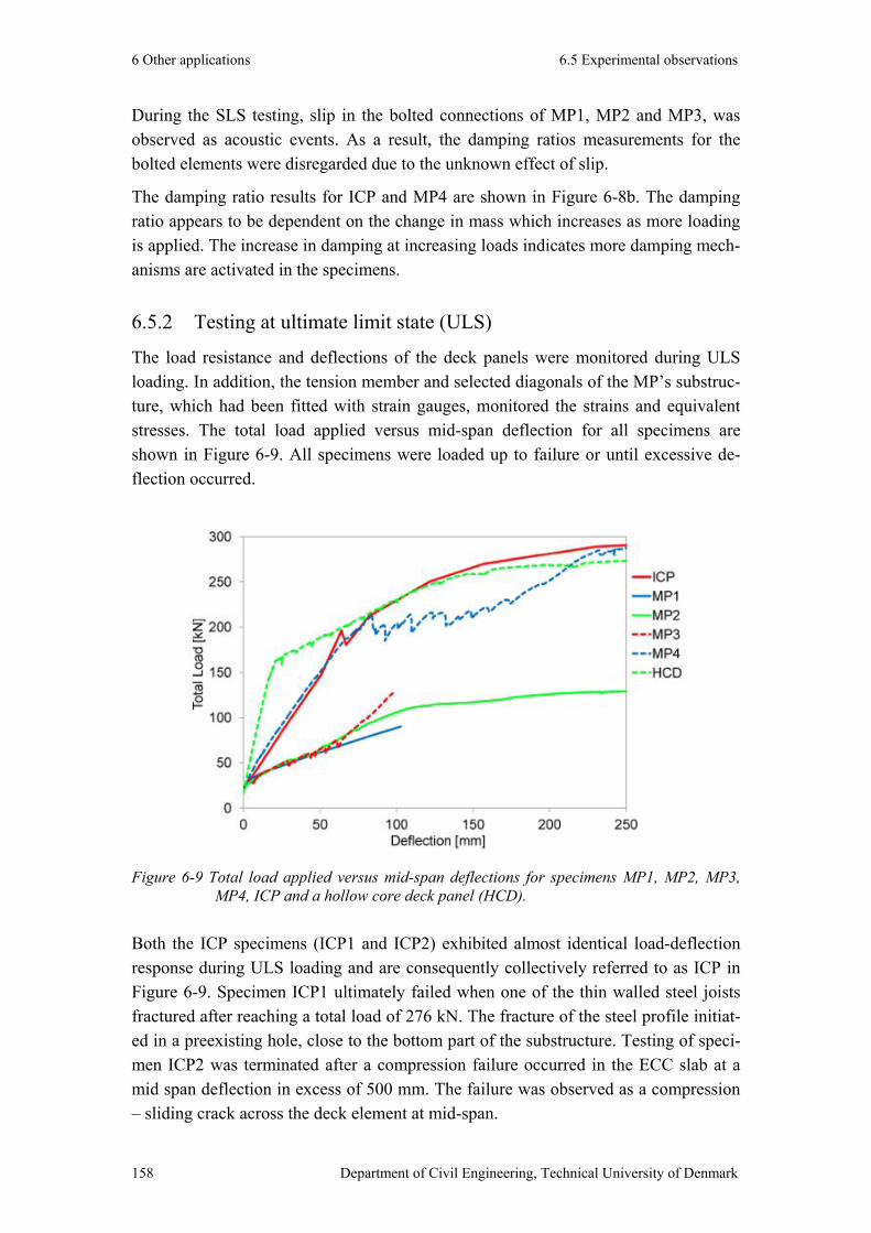
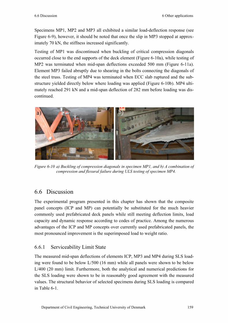
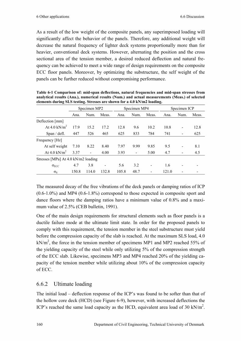
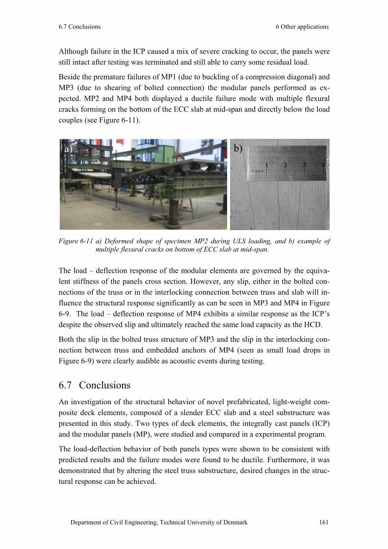


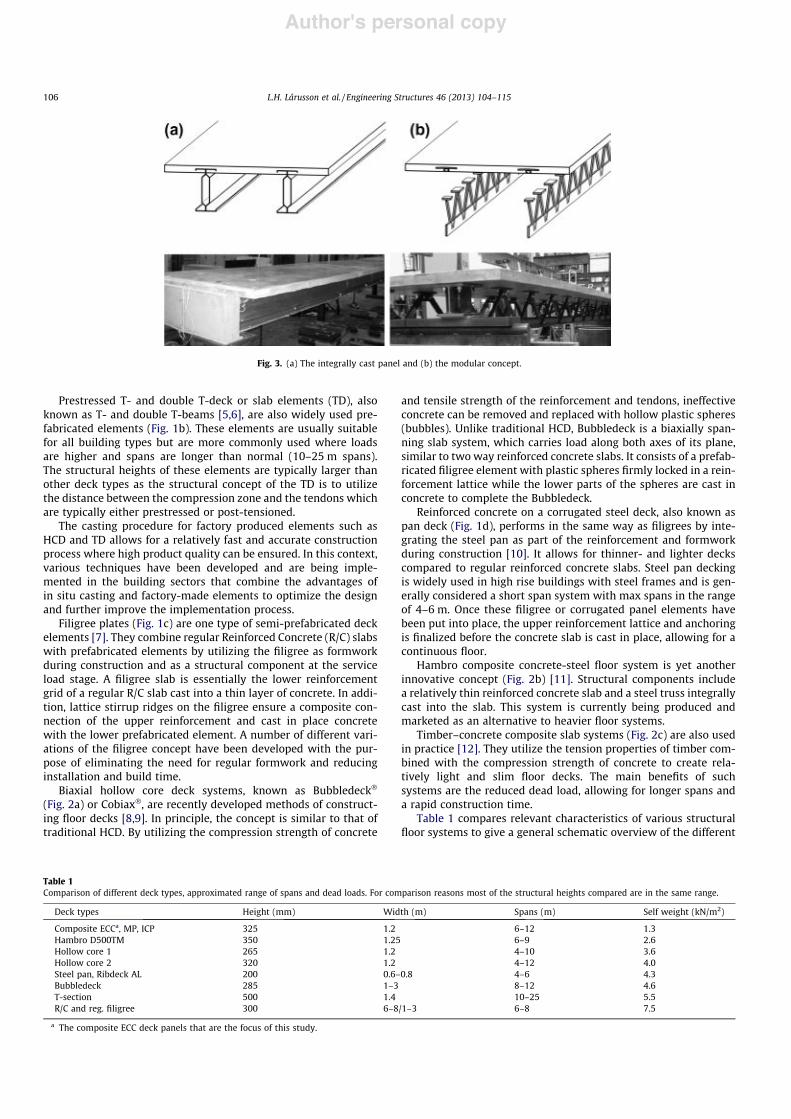

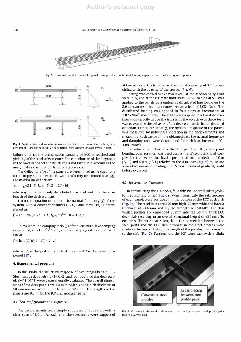
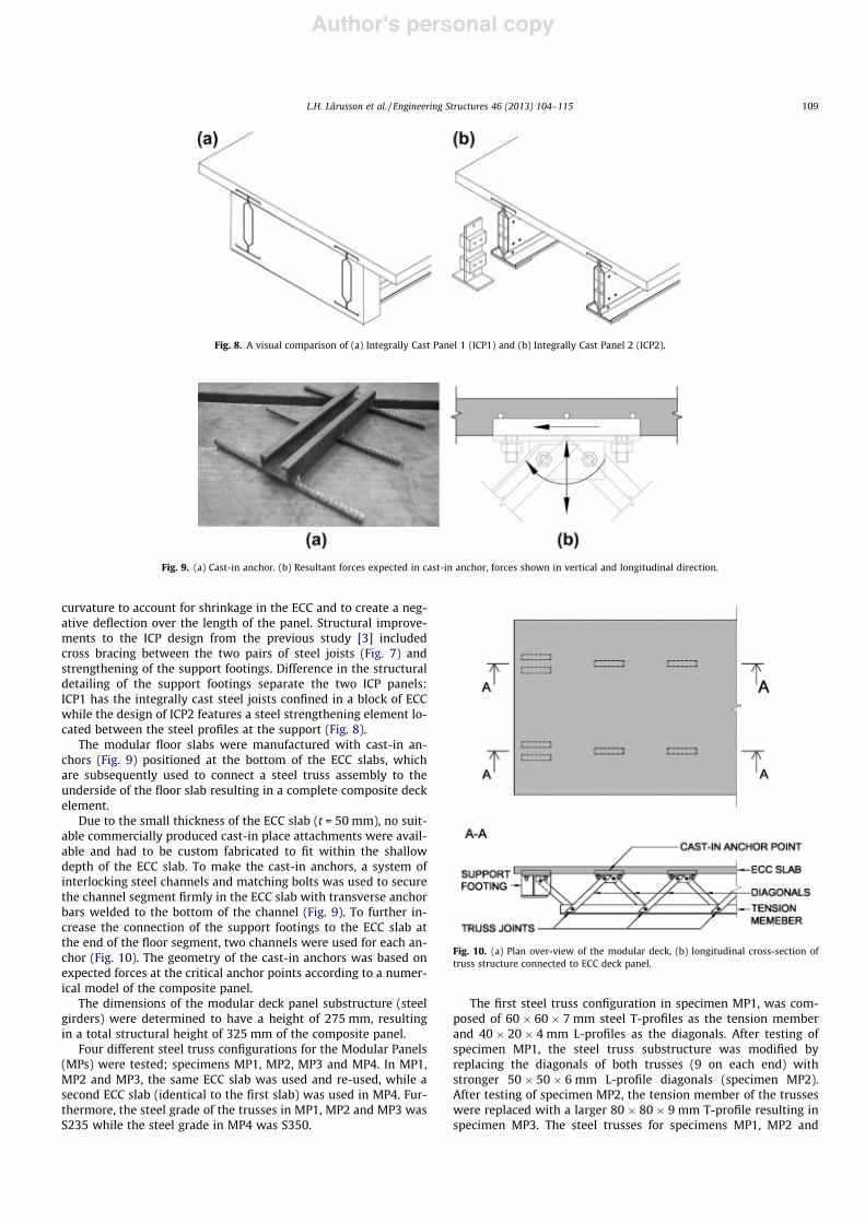
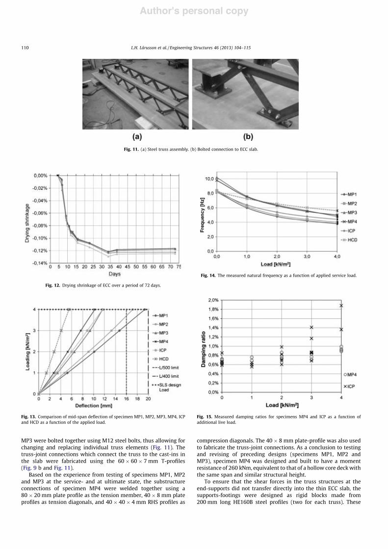
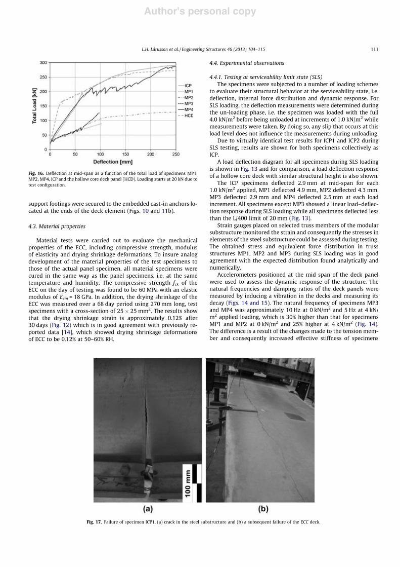


![High Ductile Behavior of a Polyethylene Fiber …...concrete members [6]. Although some studies have been conducted on fiber-reinforced geopolymer composites [7-10], these studies](https://static.fdocuments.net/doc/165x107/5f0df2297e708231d43cdc36/high-ductile-behavior-of-a-polyethylene-fiber-concrete-members-6-although.jpg)