Development of Accelerated Corrosion Test Method Team • James Dante, Erica Macha, Marta Zuflacht...
27
Development of Accelerated Corrosion Test Method James F. Dante ASETS Defense 12/7/2016
-
Upload
truongdieu -
Category
Documents
-
view
234 -
download
0
Transcript of Development of Accelerated Corrosion Test Method Team • James Dante, Erica Macha, Marta Zuflacht...

Development of Accelerated Corrosion Test Method
James F. Dante
ASETS Defense12/7/2016

WP-1673: Accelerated Dynamic Corrosion Test Method Development
Performers:• SwRI, Luna, Boeing, Alcoa, UVA,
NAVSEA, ARL, AMCOMTechnology Focus• Develop an improved accelerated
corrosion test methodResearch Objectives• Use scientific understanding of
atmospheric corrosion and measurements of field environments to develop an accelerated laboratory corrosion test method
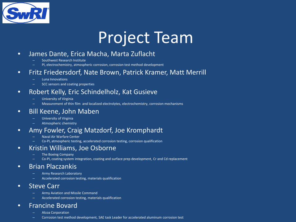
Project Team• James Dante, Erica Macha, Marta Zuflacht
– Southwest Research Institute– PI, electrochemistry, atmospheric corrosion, corrosion test method development
• Fritz Friedersdorf, Nate Brown, Patrick Kramer, Matt Merrill– Luna Innovations– SCC sensors and coating properties
• Robert Kelly, Eric Schindelholz, Kat Gusieve– University of Virginia– Measurement of thin film and localized electrolytes, electrochemistry, corrosion mechanisms
• Bill Keene, John Maben– University of Virginia– Atmospheric chemistry
• Amy Fowler, Craig Matzdorf, Joe Kromphardt– Naval Air Warfare Center– Co-PI, atmospheric testing, accelerated corrosion testing, corrosion qualification
• Kristin Williams, Joe Osborne– The Boeing Company– Co-PI, coating system integration, coating and surface prep development, Cr and Cd replacement
• Brian Placzankis– Army Research Laboratory– Accelerated corrosion testing, materials qualification
• Steve Carr– Army Aviation and Missile Command– Accelerated corrosion testing, materials qualification
• Francine Bovard– Alcoa Corporation– Corrosion test method development, SAE task Leader for accelerated aluminum corrosion test
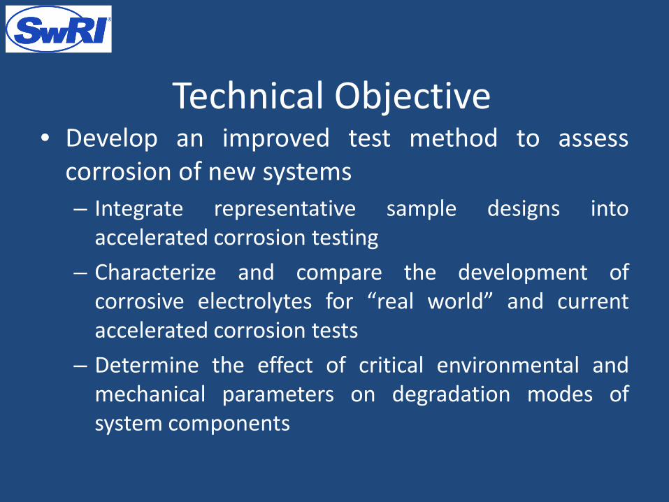
Technical Objective• Develop an improved test method to assess
corrosion of new systems– Integrate representative sample designs into
accelerated corrosion testing– Characterize and compare the development of
corrosive electrolytes for “real world” and currentaccelerated corrosion tests
– Determine the effect of critical environmental andmechanical parameters on degradation modes ofsystem components

3 Year Outdoor Exposure
• Non-Chrome Primer on AA7075/AA2024• Coating failed at fastener at Daytona and Pt. Judith• Severe corrosion in fastener hole at Pt. Judith
LAX Daytona Pt. Judith

Galvanic Couple in Fastener Hole
• Much enhanced IGC/fissure formation at Pt. Judith
• What criteria define the various exposures?
Pt. Judith7075-T6Al/SS12 months
Pt. Judith7075-T6Al/Ti12 months
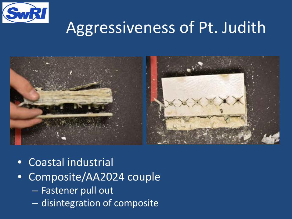
Aggressiveness of Pt. Judith
• Coastal industrial• Composite/AA2024 couple
– Fastener pull out– disintegration of composite

Knowledge Gained in WP-1673
• There are three regions of RH that are critical: RH < 50%, 50% < RH < DRG and RH > DRH,
• Exposure conditions that fall in the middle RH range will reveal potential failure on samples with crevices and galvanic couples
• The formation of corrosion within occluded sites was observed in the rivet holes for Ti and stainless steel fasteners when exposed to cyclic conditions with reduced pH suggesting the importance of these variables.
Pt. Judith7075-T6Al/SS12 months
G85-A57075-T6Al/SS1,000 hrs
UVA Trial 17075-T6Al/SS1,000 hrs
Sensitized AA5083 in modifiedASTM G85-A5
0 10 20 30 40 50Exposure Time, Hours
02E
-006
4E-0
066E
-006
Alu
min
um A
nodi
c C
urre
nt, A
02E
-008
4E-0
086E
-008
8E-0
08St
eel A
nodi
c C
urre
nt, A
40 45 50 55 60 65 70 75 80 85 90 85 80 75 70 65 60 55 50 45 40Relative Humidity, %Corrosion of steel Galvanic corrosion

COATING AND SURFACE DAMAGE

Scribe Creep-back
ASTM G85 A5, 2000 hr
ASTM B117, 2000 hr
GM9540P, 2000 hr
Top Panel 7075Bottom Panel 2024Class N water borne primerTwo fasteners on left are titaniumMiddle two fasteners are aluminumTwo fasteners on the right are CRES

Scribe Creep-back From Cycling
Increasing cycles increased scribe creep-back
• B117 is a constant test• GM9540P has a 24 hr cycle• G85A5 has a 2 hr cycle

Scribe Creep-back From Cycling
Cycle 1 Cycle 2 Cycle 3
Max RH 90% 90% 90%
Min RH 40% 65% 40%
Max RH Time (hr) 2 2 8
Min RH Time (hr) 1 1 4
Salt Dip Frequency (per wk) 1 1 1
• Additional testing to see major effects on scribe creep– # of cycles– Time of wetness– Dry RH
• Image analysis to quantify damage– % surface area attack– Volume loss
15 minute immersion 1/week5wt% NaCl + acetic acid pH=3

Surface Damage from RH Cyclinc
• Degree of damage is Cycle 1 < Cycle 2 < Cycle 3

Surface Damage from RH Cycling
• Goal is to be able to– Identify degradation in performance– Differentiate various coating systems
• Cycle 1 meets both goals within 1000 hours of testing• Cycle 2 cannot differentiate the 2 coating systems. Must have some time with RH < 50%.

Surface Damage from RH Cycling
• Aggressive testing (UVA Trial 1)– 5wt% NaCl + acetic acid
pH = 3– Very short dry time– Continuous fog during
wet time• Can distinguish chromate
(B) and non-chromate water borne (G) at 500 hours but not at 1,000
• Extremely aggressive to non-chromate system (more than Cycle 3)
500 1000500 1000500 1000Exposure Time (hours)
0
20
40
60
80
100
Sur
face
Are
a C
orro
ded
(%)
Fe Hole 2 Type GFe Hole 1 Type G Fe Hole 1 Type B Fe Hole 2 Type BFe Hole 2 Type DFe Hole 1 Type D

DEFINING WET/DRY CYCLES

Binning Criteria
• Event = at least 2 hrs in a RH range• Wet >76% RH; Dry <50% RH

Percentage of Time for Event Type
• Time normalized to total measurement time• Pt. Judith and Daytona are most aggressive environments = least
drying time• Pt. Judith spends largest amount of time in RH transition region
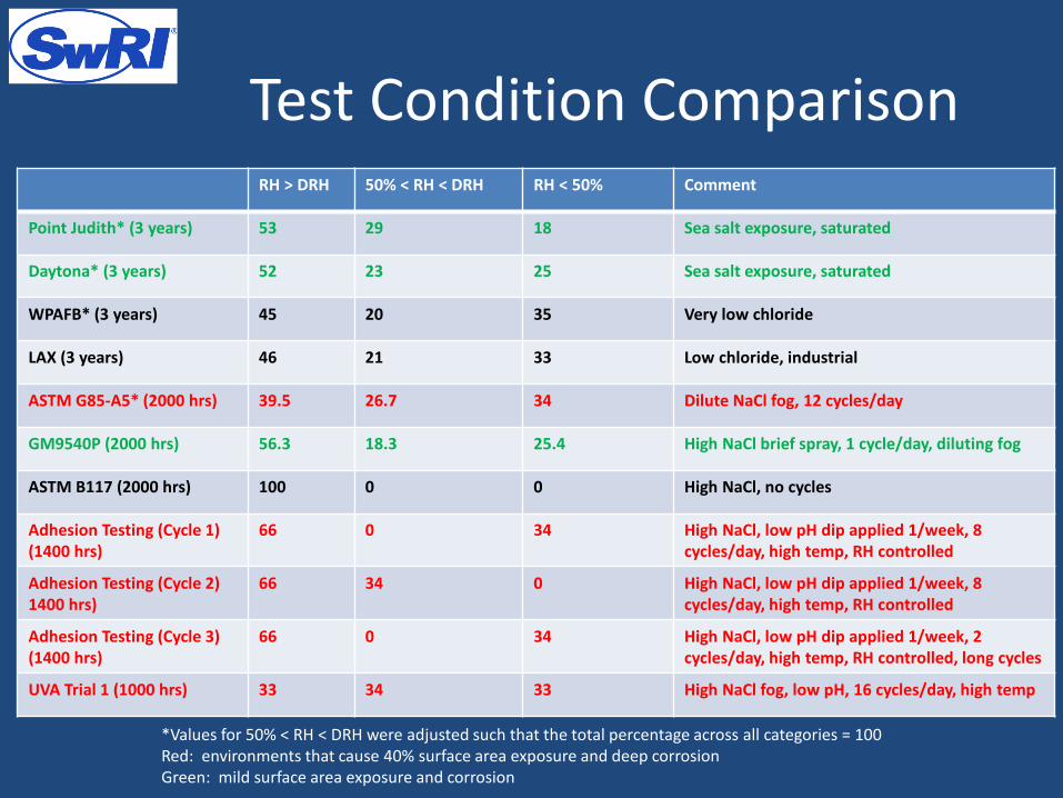
Test Condition Comparison
*Values for 50% < RH < DRH were adjusted such that the total percentage across all categories = 100Red: environments that cause 40% surface area exposure and deep corrosionGreen: mild surface area exposure and corrosion
RH > DRH 50% < RH < DRH RH < 50% Comment
Point Judith* (3 years) 53 29 18 Sea salt exposure, saturated
Daytona* (3 years) 52 23 25 Sea salt exposure, saturated
WPAFB* (3 years) 45 20 35 Very low chloride
LAX (3 years) 46 21 33 Low chloride, industrial
ASTM G85-A5* (2000 hrs) 39.5 26.7 34 Dilute NaCl fog, 12 cycles/day
GM9540P (2000 hrs) 56.3 18.3 25.4 High NaCl brief spray, 1 cycle/day, diluting fog
ASTM B117 (2000 hrs) 100 0 0 High NaCl, no cycles
Adhesion Testing (Cycle 1) (1400 hrs)
66 0 34 High NaCl, low pH dip applied 1/week, 8cycles/day, high temp, RH controlled
Adhesion Testing (Cycle 2) 1400 hrs)
66 34 0 High NaCl, low pH dip applied 1/week, 8cycles/day, high temp, RH controlled
Adhesion Testing (Cycle 3) (1400 hrs)
66 0 34 High NaCl, low pH dip applied 1/week, 2 cycles/day, high temp, RH controlled, long cycles
UVA Trial 1 (1000 hrs) 33 34 33 High NaCl fog, low pH, 16 cycles/day, high temp

Implications for Method• Coating delamination is a strong function of the time of
wetness within a given cycle. This will also likely reduce time for inhibitor depletion– RH > 50% for 65% of the time for environments where
delamination occurs– Most aggressive delamination environments have
• pH < 5• High cycle count (RH falls below 76%) OR long periods above 76% RH• Concentrated electrolyte (under RH control OR constant spray of
aggressive solution)• For cyclic corrosion testing, short time below 50% RH
results in higher corrosion rates• The duty cycle for accelerating delamination would include
relatively long exposure in the wet portion of a cycle (RH > 76%). For accelerating corrosion after delamination, short time in the drying cycle (RH < 50%) would be appropriate

NEW ACCELERATED TEST

Environmental ConditionsReagent g/L
(Reagent)g/L (Reagent)
NaCl 24.53 22.26MgCl2.6H2O 11.10 11.10Na2SO4 4.00 4.00NaNO3 3.27HCl (1N) (1 ml) (1 ml)
• Modified sea salt w/wo nitrate at pH = 3• Based on low time above 50% RH (NE#!) and very low
time above 76% RH (NE#2), expect very little delamination
• NE#1 should behave like LAX because of chemistry• NE#2 should have almost no corrosion
RH > DRH 50% < RH < DRH RH < 50% Comment
NE#1 45 13 42 Mod sea salt exposure, RH control, 12 cycle/day, pH = 3
NE#2 25 43 32 Mod sea salt with nitrate, fog control, 12 cycles/day, pH = 3

Results• 500 hours of exposure to NE#2 at NAVAIR. • General observations
– Almost all aluminum assembly types showed no corrosion in scribes, countersinks or laps. (left)
– Exception was assembly type G. These panels had dullness in the scribes and crevice corrosion in the laps. (middle)
– Steel panels had small amounts red rust visible in the scribes.– Crevice corrosion in laps was minimal and concentrated primarily at lap edges.
23
Summary: Not enough corrosion damage at 500 hours to distinguish the performance of dissimilar coating systems or fastener types.
E – 634/5205G – 7455/4082B – 7457/4102

Results• 500 hours of exposure to NE#1 at Boeing. • General observations
– Almost all aluminum assembly types showed dullness in scribes, corrosion product in the countersinks, and minimal crevice corrosion at the edge of the laps (excluding Cr6 panels). (left)
– Once again, assembly type G demonstrated the worst performance. These panels had crevice corrosion across the entire face of the lap.
– Steel panels had large amounts of red rust in the scribes and extensive crevice corrosion across the lap faces. These panels performed the worst after 500 hours.
24
Summary: 500 hours of cyclic exposure caused crevice corrosion in almost every assembly type, but not much creep back from the scribes. The morphology resembled that seen in assemblies exposed at Daytona Beach for 3 years, but chamber test was less aggressive.
B – 7450/4072 G – 7419/4023 (CRES Fasteners) D – 609/5231 (Ti Fasteners)

Results• 1000 hours of exposure to NE#1 at Boeing. • General observations
– Almost all aluminum assembly types showed dullness and some amount of corrosion product in the scribes, corrosion product in the countersinks, and minimal crevice corrosion at the edge of the laps (excluding Cr6 panels). (left)
– Again, assembly type G demonstrated the worst performance. These panels had crevice corrosion across the entire face of the lap similar to LAX 3 year exposure.
– Steel panels had large amounts of red rust in the scribes and extensive crevice corrosion across the lap faces. These panels performed the worst after 1000 hours.
25
Picture of Boeing panel, Assembly type B.
Summary: 1000 hours of cyclic exposure caused crevice corrosion in almost every assembly type, but not much creep back from the scribes. The morphology resembled that seen in assemblies exposed at Daytona Beach for 3 years, but chamber test was more aggressive.
B – 7454/4015 G – 7431/4002 (Ti Fasteners) D – 631/5229 (CRES Fasteners)

Conclusions• Still working to quantify damage in NE#1, NE#2 and 3
year outdoor exposure environments• Based on wet/dry cycle in NE#1 and NE#2, expected
little corrosion within 1,000 hours. Experiment validated expectation
• We have been able to replicate Daytona behavior in laps but not yet for coating delamination after exposure to NE#1 for 1,000 hours
• We have not yet replicated Pt. Judith observations within 1,000 hours but know which variables to change
• In order to mimic coating delamination at fasteners and scribes and mimic IGC corrosion along the galvanic fasteners, must increase time above 76% RH, to over 50% RH and reduce dry time to < 20%

Questions?