Development aspects of a high temperature heat pipe heat ...
138
Development aspects of a high temperature heat pipe heat exchanger for high temperature gas-cooled nuclear reactor systems by Ryno Laubscher Thesis presented in fulfilment of the requirements for the degree of Master of Science in Engineering (Mechanical) in the Faculty of Engineering at Stellenbosch University Supervisor: Mr Robert Thomas Dobson March 2013
Transcript of Development aspects of a high temperature heat pipe heat ...

Development aspects of a high temperature heat pipe heat exchanger for high temperature gas-cooled
nuclear reactor systems
by
Ryno Laubscher
Thesis presented in fulfilment of the requirements for the degree of Master of Science in Engineering (Mechanical) in the Faculty of
Engineering at Stellenbosch University
Supervisor: Mr Robert Thomas Dobson
March 2013

i
Declaration
By submitting this thesis electronically, I declare that the entirety of the work contained therein is my own, original work, that I am the sole author thereof (save to the extent explicitly otherwise stated), that reproduction and publication thereof by Stellenbosch University will not infringe any third party rights and that I have not previously in its entirety or in part submitted it for obtaining any qualification.
Signature: …………………………………………………
Ryno Laubscher
Date: …………………………………………………
Copyright © 2013 Stellenbosch University
All rights reserved
Stellenbosch University http://scholar.sun.ac.za

ii
Abstract
Development aspects of a high temperature heat pipe heat exchanger for high temperature gas-cooled nuclear reactor systems
R. Laubscher
Department of Mechanical and Mechatronic Engineering Stellenbosch University Private Bag X1, 7802, Matieland, South Africa
High temperature heat sources are becoming an ever-increasing imperative in the process industry for the production of plastics, ammonia and fertilisers, hydrogen, coal-to-liquid fuel and process heat. Currently, high temperature reactor (HTR) technology is capable of producing helium temperatures in excess of 950°C; however, at these temperatures, tritium, which is a radioactive contaminant found in the helium coolant stream, is able to diffuse though the steel retaining wall of the helium-to-steam heat exchanger. To circumvent this radioactivity problem, regulations require an intermediate heat exchange loop between the helium and the process heat streams. In this paper, the use of a uniquely designed sodium-charged heat pipe heat exchanger is considered, and has the distinct advantage of having almost zero exergy loss as it eliminates the intermediate heat exchange circuit.
In order to investigate this novel heat pipe heat exchanger concept, a special intermediate-temperature (± 240°C) experimental hea t pipe heat exchanger (HPHE) was designed. This experimental HPHE uses Dowtherm A as working fluid and has two glass windows to enable visual observation of the boiling and condensation two-phase flow processes. A high temperature air-burner supply simulates the high temperature stream, and the cold stream is provided by water from a constant-heat supply tank. This experimental apparatus can be used to evaluate the validity of steady-state and start-up transient theoretical models that have been developed.
This paper will highlight the special design aspects of this HPHE, the theoretical model and the solution algorithm described. Experimental results will be compared with the theoretically calculated results. The theoretical model will then be used to predict the performance of a high temperature (sodium working fluid at 850°C) HPHE will be undertaken and conclusions and recommendation made.
Key words: Heat pipe heat exchanger, boiling, condensation, thermal-hydraulic mathematical simulation
Stellenbosch University http://scholar.sun.ac.za

iii
Opsomming
Ontwikkelings aspekte van ‘n hoë temperatuur hitte pyp warmte uitruiler vir gebruik in hoë temperatuur gas-verkoelde kern reaktor sisteme
R. Laubscher
Departement van Meganiese en Megatroniese Ingenieurswese Universiteit Stellenbosch Posbus X1, 7802, Matieland, Suid-Afrika
Hoë temperatuur hitte bronne is besig om ‘n toenemende noodsaaklikheid te raak in die proses industrie vir die vervaardiging van plastieke, ammoniak, kunsmis, waterstof, steenkool-tot-vloeibare brandstof en proses hitte. Huidige hoë temperatuur reaktor tegnologie is in staat om helium te verhit tot temperature hoër as 950 °C, maar by sulke hoë temperature is die vorming van tritium, wat ‘n radioaktiewe produk is, in die helium verkoeling stroom wat deur die reaktor vloei, ‘n probleem. Die tritium is in staat om deur die staal wand van ‘n enkel fase warmte uitruiler te diffundeer. Om hierdie radioaktiewe probleem te uitoorlê, stel huidige regulasies voor dat ‘n oorgangs hitte uitruil lus gebruik raak tussen die helium en proses strome van die reaktor stelsel. In hierdie tesis word ‘n unieke natrium gevulde hitte pyp warmte uitruiler nagevors, hierdie ontwerp het die voordeel dat dit geen “exergy” verlies het omdat dit nie ‘n oorgangs hitte uitruil lus benodig nie.
Hierdie unieke konsep was nagevors deur ‘n spesiale oorgangs temperatuur (± 230 °C) eksperimentiële hitte pyp warmte uitruiler te ontwerp. Hierdie eksperimentiële hitte pyp warmte uitruiler gebruik Dowtherm A as oordrags medium tussen die warm en koue strome en het twee glas venters waardeur die kook en kondensasie van die oorgangs medium dop gehou kan word. ‘n Hoë temperatuur verbrander simuleer die warm stroom deur die reaktor en die koue stroom word gesimuleer deur koue water. Die eksperimentiële opstelling sal gebruik word om die tyd afhangklike en tyd onafhangklike teoretiese wiskundige modele te valideer.
Hierdie tesis sal die spesiale ontwerp aspekte van die hitte pyp warmte uitruiler, teoretiese modelle en oplos algoritme te bespreek. Eksperimentiele resultate sal met die teoretiese resultate vergelyk word en dan sal die teoretiese modelle gebruik word om ‘n natrium gevulde warmte uitruiler te simuleer. Gevolgtrekkings en aanbevelings sal in die lig van die resultate verskaf word.
Sleutel woorde: Hitte pyp warmte uitruiler, kook, kondensasie, termo-hidroliese wiskundige simulasie
Stellenbosch University http://scholar.sun.ac.za

iv
Dedication
Dedicated to the Almighty, Christ Jesus, who has given me knowledge, discipline and talent.
Stellenbosch University http://scholar.sun.ac.za

v
Acknowledgements
I would like to express my sincere acknowledgement of the following people:
My supervisor, Mr Robert Dobson, for guidance, tutelage, patience and continuous encouragement for the duration of this research. His inexhaustible enthusiasm and knowledge made this project a meaningful yet enjoyable endeavour.
The staff at the Department of Mechanical Engineering, particularly Kobus and Ferdie Zietsman, for their help and guidance during the experimental design and the installation process. Particular thanks to Calvin Harremse and Kobus Samuels, for their help during the physical installation of the experimental device.
Laub Engineering, specifically Eben Laubscher, my father, for all his help and guidance during the fabrication of the heat exchanger and the installation and maintenance processes. Also Manus Lotter, for his help in the procurement of parts.
Stellenbosch University http://scholar.sun.ac.za

vi
Table of Contents
1. Introduction .............................................................................................................................. 1
2. Literature study ........................................................................................................................... 4
2.1 Historical development of heat pipe heat exchangers ............................................................ 4
2.2 Heat pipe technology ............................................................................................................. 4
2.3 HTGR regulatory requirements .............................................................................................. 6
2.4 Design of the conceptual heat pipe heat exchanger .............................................................. 6
2.5 Heat transfer characteristics of an HPHE .............................................................................. 9
2.7 Research related to numerical modelling ............................................................................. 15
3. Thermal-hydraulic modelling of the proposed heat pipe heat exchanger ................................ 17
4. Experimental setup, procedure and results ............................................................................... 27
4.1 Experimental setup .............................................................................................................. 28
4.2 Experimental procedure....................................................................................................... 36
4.3 Experimentally measured data ............................................................................................ 37
5. Experimental data processing, observations, numerical solution validation and discussion ...... 40
5.1 Heat loss through insulation and support structure and experimental energy account ......... 40
5.2 Boiling and condensation heat transfer coefficients ............................................................. 41
5.3 Experiment observations, analysis and comparison to numerical simulation ....................... 51
Comparison of experimental data to numerical simulation ................................................................... 54
6. Preliminary full-scale sodium-charged HPHE ......................................................................... 61
6.1 Thermodynamics and reactor loop layout ....................................................................... 61
6.2 Thermal-hydraulic design of the different heat pipe-type heat exchangers with various boiling correlations implemented ............................................................................................... 65
7. Conclusions and recommendations ....................................................................................... 68
7.1 Conclusions ......................................................................................................................... 68
Stellenbosch University http://scholar.sun.ac.za

vii
7.2 Recommendations ............................................................................................................... 72
References ................................................................................................................................... 73
Appendix A: Computer program logical algorithms, flow diagrams and program listing ................. 76
A.1 Steady-state computer program .......................................................................................... 76
A.2 Numerical simulation (time dependent) ............................................................................... 89
Appendix B: Polynomial regression data of working fluids and other fluids pertaining to the functionality of the thermal hydraulic models ............................................................................... 100
Appendix C: Thermodynamic calculations for full-scale preliminary design ................................. 102
Appendix D: Preliminary full-scale design graphs........................................................................ 108
Appendix E: Calibration data ....................................................................................................... 111
Appendix F: Experimental data of heating of heat pipe heat exchanger ...................................... 114
Appendix G: Steady operation data from Heating Test 1 compared to numerical simulation ....... 117
Appendix H: Numerical simulation output for heating without burping and steady operation ....... 119
Stellenbosch University http://scholar.sun.ac.za

viii
List of figures
Figure 1.1: Current regulatory power loop (a) and conceptual HPHE design (b)………….……2
Figure 2.1: Heat pipe and thermosyphon…………………………………………….……………..5
Figure 2.2: Geometrical layout of concept heat pipe heat exchanger………………….………..8
Figure 2.3: Boiling curve………………………………………….………………………………….10
Figure 2.4: Photograph of various boiling regimes………………………………….……………10
Figure 2.5: Laminar film condensation on horizontal tube banks…………………….…………13
Figure 2.6: Fixed control volume with inlets and outlets………………………………..………..14
Figure 3.1: Concept drawing of heat pipe heat exchanger……………………………..……….16
Figure 3.2: Discretisation of heat exchanger into a series of control elements, each comprising hot heating, two-phase and cold cooling control volumes………………………….17
Figure 3.3: Depiction of three control volumes for the i-th element in the system………….…18
Figure 3.4: Thermal resistance diagram for the numerical solution of a control volume in the system………………………………………………………………………………………..……..…22
Figure 4.1: Drawing of experimental heat exchanger with selected dimensions………….…..28
Figure 4.2: Experimental heat pipe heat exchanger (photograph)………………….… ……….28
Figure 4.3: Schematic layout of experimental setup…………………………………………..….29
Figure 4.4: Photograph of the heat pipe heat exchanger and hot gas supply burner…….…..31
Figure 4.5: Experimental heat exchanger with its thermal insulation…………………..…….…31
Figure 4.6: Location of the thermocouple junctions where temperature readings were taken along the length of the heat exchanger……………………………………………….……………32
Figure 4.7: Positions of thermocouples for a single sensor bank…………………….…………33
Figure 4.8: Diagram of setup of temperature-logging equipment ………………………………34
Figure 4.9: Calibration setup for thermocouples………………………………………………….34
Figure 4.10: Example of calibration curve for thermocouples……………………..……....……35
Figure 4.11: Cooling temperatures of the vapour and liquid……………………………..….…..37
Figure 4.12: Temperature readings of the liquid and vapour sensors during Heating Test 1 at Sensor Bank 1……………………………………………………….…………………………….…37
Figure 5.1: Heat loss from heat exchanger to environment…………………………..…………39
Figure 5.2: Energy balance in experimental heat pipe heat exchanger ……………………….40
Figure 5.3: Photograph of nucleate boiling on evaporator tube…………………….…………..41
Stellenbosch University http://scholar.sun.ac.za

ix
Figure 5.4: Experimental boiling heat transfer coefficient results………………………….……42
Figure 5.5: Experimental and theoretical boiling heat transfer coefficients plotted as a function of the evaporator wall heat flux………………………………………………..……………………42
Figure 5.6: Experimental and new correlation boiling heat transfer coefficients………………………………………………………………………………..…………..44
Figure 5.7: Theoretical (equation 5.9) heat transfer coefficient as a function of its experimental heat transfer coefficient (equation 5.6)………… …………………………………………..……..45
Figure 5.8: Condensate formation on the condenser………………………………………….…45
Figure 5.9: Experimental and theoretical (equation 2.23) condensation heat transfer coefficients………………………………………………………………………….……………..….47
Figure 5.10: Theoretical (equation 5.19) and experimental condensation heat transfer coefficient results…………………………………………………………..………………...………48
Figure 5.11: Theoretical condensation heat transfer coefficient (equation 2.23) as a function of the experimental results……………………………………………………………………...…..50
Figure 5.12: Theoretical condensation heat transfer coefficient (equation 5.19) as a function of the experimental results……………………………………………………………….………….49
Figure 5.13: Temperature readings as a function of time for Heating Test 1…………….……50
Figure 5.14: Temperature readings as a function of time for Heating Test 2…………...……..51
Figure 5.15: Comparison of experimental data and numerical simulation of heating phase data (x = 0.055 m)………………… …………………………………………….…………………..53
Figure 5.16: Comparison of experimental data and numerical simulation of heating phase data (x = 0.245 m)………………… …………………………………………………….…………..54
Figure 5.17: Comparison of experimental data and numerical simulation of heating phase data (x = 0.425 m)…………………………………………… …………….… …………………….54
Figure 5.18: Comparison of experimental data and numerical simulation of heating phase data (x = 0.615 m)……………………………………………………….……….… ……………….55
Figure 5.19: Axial temperature distribution for the computer program and the experimental data………………………………………………………………………..……………...……………56
Figure 5.20: Axial variation of boiling heat transfer coefficient for the computer program and the experimental results…………………………………………………………………….……….57
Figure 5.21: Film condensation heat transfer coefficient for the computer program and experimental data as a function of axial distance…………………………………………….…..57
Figure 5.22: Temperature profiles of the hot stream, cold stream and working fluid for the numerical simulation and the experimental heat exchanger along the length of the evaporator tube……………………………………………………………………………………..……………..58
Figure 6.1: T-s diagram for reheat Rankine vapour power cycle…………….…..60
Figure 6.2: P-h diagram for reheat Rankine vapour power cycle……………..….61
Stellenbosch University http://scholar.sun.ac.za

x
Figure 6.4: Primary loop and heat exchanger layout of single high temperature gas-cooled reactor system………………………………………………………………………………………..63
Stellenbosch University http://scholar.sun.ac.za

xi
List of tables
Table 1: Liquid metals used in heat pipes ………………………………………………………….7
Table 2: Properties of Dowtherm A…………………………………………………………….…….8
Table 3: Range of liquid-metal data analysed for pool boiling…………………………………..13
Table 4: Summary of external heat transfer coefficient correlations and equations for the evaporator and condenser………………………………………………………………………..…24
Table 5: COM_HPHE_STEADY_SIM output for sized design variables………………….……27
Table 6: Process devices model numbers, serial numbers and materials………………….….30
Table 7: Heat transfer rates and pressure comparison between numerical simulation and experimental results……………………………..…………………………………………………...58
Table 8: Thermodynamic properties at each point during the process…………………………62
Table 9: Mass flow rates for primary and secondary loops in high temperature gas-cooled reactor design………………………………………………………………………………………...62
Table 10: Inlet/outlet temperatures for each of the required heat exchangers and the required heat transfer rate from the helium to the steam…………………………………………..………62
Table 11: Sized design parameters for reheat heat pipe heat exchanger………………..……65
Table 12: Sized design parameters for superheater heat pipe heat exchanger………...…….65
Table 13: Sized design variables for economizer heat pipe heat exchanger using Shah…………………………………………………………………………………………….66
Table 14: Properties of the steam generator……………………………………………...……....66
Table 15: Maximum percentage error of steady numerical simulation results………...………70
Stellenbosch University http://scholar.sun.ac.za

xii
Nomenclature
Symbols
A Area, m
aL Thermal diffusivity, m2/s
B Fluid property coefficient in Reynolds transport theorem
b Fluid Specific fluid property coefficient in Reynolds transport theorem
Csf Rohsenow coefficient
cp Specific heat (constant pressure), J/kg.K
cv Specific heat (constant volume), J/kg.K
d Diameter, m
e Specifc total energy, J/kg
dbub Bubble departure diameter, m
FPF Gorenflo pressure correction factor
f Friction factor
G Mass velocity, �����
g gravity, m/s2
H Total enthalpy, J
h Heat transfer coefficient, ����
h Specifc enthalpy, J/kg
hfg Latent heat of vaporisation, J/kg
ID Internal diameter
i Numerical element designation variable
j Numerical time designation variable
k, Thermal conductivity W/m.K
L Length, m
Stellenbosch University http://scholar.sun.ac.za

xiii
l* Characteristics length,
m Mass, kg
� Mass flow rate, kg/s
N Amount of evaporator/condenser tubes
N Number of iterations
Nu Nusselt number, ��
n Rohsenow power constant
nf Gorenflo power variable
OD Outside diameter
P Pressure, Pa
Pr Prandtl number, ���
Pr Reduced pressure, ������
Pcrit Critical pressure, Pa
� Heat transfer rate, W
��� Heat transfer rate into control volume, W
���� Heat transfer rate out of control volume, W
����� Heat transfer rate from evaporator control volume, W
� ��� Heat transfer rate into condenser control volume, W
� �!! Heat loss through insulation and support structure, W
" Heat flux, W/m2
R Thermal resistance, °C/W
Re Reynolds number, #���
Rp, Rpo Surface roughness, µm
ri Evaporator and condenser internal tube radius, m
Stellenbosch University http://scholar.sun.ac.za

xiv
s Specific entropy, J/kg.K
T Temperature, °C
Ts Surface temperature, °C
Tsat Saturation temperature of vapour, °C
Tb Boiling temperature, °C
Ti* Temperature adjustment variables for steady-state program if Q %&'( < Q *+,-, °C
Ti# Temperature adjustment variables for steady-state program if Q %&'( > Q *+,-, °C
t Time, s
U Total internal energy, J
U Overall heat transfer coefficient, °C/W
u Fluid velocity, m/s2
u Specific internal energy , J/kg
V Volume, m3
W Work done, J
x Quality
x Axial length along evaporator and condenser tubes, m
Greek symbols
α0 Gorenflo reference heat transfer rate, 2100 W/m2K
β Contact angle, 35°
δ Condensate film thickness, m
∆Tb Evaporator surface and internal liquid temperature difference, Ts-Tsat
∆x Numerical element width, m
∆H Change in total enthalpy of control volume, J
∆U Change in total internal energy of control volume, J
∆t Time step, s
ηth Thermal efficiency, %
Stellenbosch University http://scholar.sun.ac.za

xv
θ Total energy of flowing fluid, J/kg
µ Fluid viscosity, kg/ms
ν Kinematic viscosity, m2/s
ρl Liquid density, kg/m3
ρv Vapour density, kg/m3
σ Surface tension, N/m
φ Angle around circumference of tube
Г Mass flow per unit width, kg/ms
Subscripts
atm Atmosphere
avg Average
b Boiling
c Condensing
D Diameter
cold Cold stream control volume
cond Condenser
co Condenser outside
cw Condenser wall
ci Condenser inside
evap Evaporator
eo Evaporator outside
ew Evaporator wall
ei Evaporator inside
exp Experimental
g Gas
HE Heat exchanger
Stellenbosch University http://scholar.sun.ac.za

xvi
hot Hot stream control volume
i Numerical element designation, inside, interfacial
in Into control volume, or into experimental heat exchanger
inlet Inlet into heat pipe heat exchanger
int fluid Internal fluid control volume
l Liquid
lv Liquid and vapour together
loss Loss
N Final numerical element in a array
n Time designation variable used during experimental processing
new New iteration value
o Outside
out Out of control volume, or out of experimental heat exchanger
outlet Outlet of the heat pipe heat exchanger
old Previous iteration value
s Surface
sim Simulation
sat Saturation
sys System
v Vapour
Superscript
j Time designation variable in numerical simulation
t Time
∆t Time step
Abbreviations
CV Control volume
Stellenbosch University http://scholar.sun.ac.za

xvii
CS Control surface
HPHE Heat pipe heat exchanger
HTGR High temperature gas-cooled reactor
PRT Platinum reference thermometer
NGNP Next generation nuclear power
Stellenbosch University http://scholar.sun.ac.za

1
1. Introduction
The utilisation of nuclear power plants for the production of hydrogen and process heat is receiving increased interest because of dwindling fossil fuel reserves. High temperature process heat is becoming an increasingly important imperative in industrial production processes such as desalination, synthetic oil production, oil refining and biomass-based ethanol production and, for the future, hydrogen production, not to mention increasing electrical power demands. For the production of process heat or the generation of electricity one of the methods require a thermal device used to transfer the thermal energy from the reactor coolant stream to steam or secondary coolant in the most efficient way possible. This is accomplished through the utilisation of heat exchangers. (Sabharwall, 2008)
One of the methods of producing high temperature process heat is by the use of high temperature gas-cooled reactors which uses helium a reactor coolant. One of the many challenges in the design of heat exchangers for high temperature nuclear power cycles is the radioactive contamination of the helium coolant stream as it moves through the reactor. When uranium fissions, it emits neutrons and gamma rays, as shown in equation 1.1. (King, 1963)
/012 + 456 → /01890 → :5;5<5 + :0;0<0 + 2.5 456 + @4@ABC90
→ /01890 + E (1.1)
The neutrons so formed react with helium from the reactor coolant stream, according to
F@01 + 456 → F55 + F51 (1.2)
The concern of tritium formation or contamination originates because, at high temperatures, materials have a high permeability to tritium and tritium is harmful to the environment and humans (Jousse, 2007). The contamination spreads due to the graphite dust (from the graphite spheres in a PBMR system) that collects in the helium stream and that is then transported to the heat exchanger and from there to other subsystems. The tritium is able to diffuse through the steel retaining wall of the helium-to-steam heat exchanger. Therefore current regulations require an intermediate heat exchange loop between the helium and the steam to prevent radioactive leakage from the reactor coolant (International atomic energy agency, 1991) through acting as a diffusion barrier. It is from the need for an intermediate heat exchange barrier, high temperature technology and high pressure systems that the purpose and idea for this thesis originated by proposing the use of a single vessel-single pool thermosyphon-based heat pipe heat exchanger as the primary heat exchanger between the primary coolant and the secondary loop. Therefore the primary and secondary loops are physically separated and high temperature heat transfer can be achieved at low pressures due to the high boiling temperatures at low pressures (example sodium). By eliminating the need for the secondary loop, the pumping costs and capital costs of the plant will decrease; another benefit of eliminating the secondary loop is increased efficiency do to removal of extra input pumping requirements. The current regulatory requirements and the proposed alternative for the nuclear power cycle are illustrated in Figure 1.1. (Slabber, 2009)
Stellenbosch University http://scholar.sun.ac.za

2
The heat exchanger model shown in Figure 1.1b would eliminate the need for an intermediate heat exchange loop. The suggested alternative is a special type of heat pipe heat exchanger that implements the heat pipe energy transfer mechanism in a large vessel with a single working fluid pool. The heat is supplied to an evaporator section, the energy then flows into a liquid pool and nucleate boiling occurs. In turn, the vapour generated transfers the energy to the condenser section, where the heat is transferred to the process stream. The suggested heat exchanger uses sodium as working fluid and will have an operating temperature of 850°C, correspondi ng to an operating pressure of about 1 bar absolute.
Reactor
Shell-and-tube HEs
Figure 1.1: Current regulatory power loop (a) and conceptual HPHE design (b)
b) Conceptual Heat pipe heat exchanger design
a) Current regulatory requirement
Reactor
• Electricity generation
• H2
production • Process
heat
Primary loop
Intermediate loop Process loop
• Electricity generation
• H2
production • Process
heat
Stellenbosch University http://scholar.sun.ac.za
3
In order to investigate the HPHE (heat pipe heat exchanger), a literature study was undertaken. The following areas were reviewed: historical development of HPHE, heat exchanger technology, HTGR technology and design requirements of a heat exchanger. Further research was done that contributed to the design of the heat exchanger. This included the type of working fluid, geometrical design considerations, flow arrangement, nucleate pool boiling and laminar film condensation heat transfer.
From the information gathered in the literature study, two numerical simulation models were generated. The first was a numerical model that was used to simulate the start-up heating to steady-state process, whereas the other simulated the steady-state condition for the HPHE. To validate these simulation models, an experimental HPHE was designed and tested. The experimental heat exchanger operated at an intermediate temperature range between 210 and 260°C. The experimental heat exchanger used Dowtherm A as the working fluid, rather than sodium. This drop in temperature from the intended full-scale requirement of 850°C was due to the safety re gulations at the Department of Mechanical Engineering at Stellenbosch University.
In this thesis, the following aspects of the suggested HPHE were addressed in the design aspects: thermal-hydraulic numerical models, experimental design and setup and then experimental and numerical data. The experimental data was then used to validate the thermal-hydraulic models. These computer programs were used to size a preliminary full-scale design of the HPHE using sodium and input values for an HTGR system. Finally, detailed conclusions and recommendations are provided.
Stellenbosch University http://scholar.sun.ac.za

4
2. Literature study
This literature study contains the following aspects pertaining to the research and development of the conceptual heat pipe heat exchanger:
• Historical development of heat pipe heat exchangers. • Heat pipe heat exchanger technology. • HTGR research pertaining to conceptual HPHE, current regulatory requirements
and operating values. • Design of an HPHE and aspects pertaining to it: working fluid, geometrical design
and flow arrangement. • Nucleate pool boiling and laminar film condensation heat transfer. • Numerical modelling research, such as the use of conservation laws and the
Reynolds transport theorem.
2.1 Historical development of heat pipe heat exchangers
The first heat pipe device was the Perkins tube, which was patented by A.M. Perkins and his son, J. Perkins. The heat pipe transferred thermal energy using the single or two-phase flow of a working fluid from a furnace to a boiler. The Perkins tube consisted of a sealed space partially filled with water. The working fluid was vaporised by boiling and the vapour that formed then moved through pipes to a space where it was condensed. The liquid formation occurred by means of extracting heat by convection. Thus, free convection heat and mass transfer occurred between the evaporator and condenser section. The early applications of the Perkins tube were in boilers and fire boxes in the locomotive industry.
In 1929, Gay produced a concept that utilises fins on the Perkins tube to increase the heat transfer area. He then placed a number of finned Perkins tubes vertically, where the heating and cooling stream across the exterior of the heat pipe were divided by means of a separating plate. This configuration of the tubes was the first stepping stone in the development of current heat pipe technology (Dunn, 1994).
Gaugler then introduced a tube that contained a wick and a small amount of working fluid. When thermal energy is added to the evaporator section, the working fluid present in the capillary structure of the heat pipe is vaporised and then travels to the condenser section, where the thermal energy is extracted and the fluid condenses. The capillary forces in the capillary structure then drives the condensed working fluid back to the evaporator section (Dunn, 1994).
In 1963, Grover demonstrated that heat pipes can be used as high temperature heat transmission devices (Faghri, 1995). Nozu, in 1968, presented his concept of an air heater utilising a bundle of finned heat pipes. This became known as the first heat pipe heat exchanger and the applications of heat pipes were specifically developed for application in space during the sixties. (Korn, 2008)
2.2 Heat pipe technology
In this section the difference between heat pipes and thermosyphons will be explained and the advantages of heat pipe heat exchangers will be given.
Stellenbosch University http://scholar.sun.ac.za

5
Heat pipes and thermosyphons
The heat pipe is an evaporator-condenser system, where the one end is heated and the other end cooled. At the end at which heat is applied, boiling occurs inside the heat pipe. This evaporates the working fluid. The vapour formed at the evaporator end then travels through the heat pipe to the other end, where heat is extracted. The movement of the vapour is due to the pressure difference between the evaporator and condenser sections. As the heat is taken out of the vapour, it condenses. The liquid condensate then returns to the evaporator end and the process is repeated. There are two main classes of heat pipes, which are shown in Figure 2.1. One is the traditional heat pipe and the other a thermosyphon. (Mills, 1995)
The main difference between heat pipes and thermosyphons is that heat pipes use capillary forces in the wicking structure to transfer the liquid back to the evaporator section, whereas thermosyphons have no wicking structure and uses gravitational forces to transfer the liquid condensate from the condenser section back to the evaporator section. Thermosyphons have a distinct advantage, as there is no additional flow resistance due to the wicking structure, but have a disadvantage in that thermosyphons must be configured so that the low temperature sink is located above the high temperature reservoir (Mills, 1995).
Heat pipe heat exchangers and their advantages
Heat pipe heat exchangers are liquid-coupled indirect-transfer type heat exchangers. These heat exchangers employ multiple heat pipes or thermosyphons to transport heat between two fluid streams. HPHE uses vaporisation and condensation processes to transfer heat between the cold and hot streams without the use of pumps, fans or compressors (eliminating required pump in intermediate loop), whereas other types of heat exchangers, such as shell-and-tube heat exchangers, use single-phased convective
Liquid condensate
Wick
Vapour
Heating
Cooling
b) Heat pipe a) Thermosyphon
Heating
Cooling
Vapour
Liquid
Figure 2.1: Heat pipe and thermosyphon
Liquid condensate
Stellenbosch University http://scholar.sun.ac.za

6
heat transfer between the high and low temperature streams and thus require pumps or fans to force the fluid through the heat exchanger core.
Advantages that a heat pipe offers are that (Faghri, 1995):
• It has no moving parts or auxiliary power requirements and therefore has high reliability and low maintenance costs.
• The two different fluid streams are completely separated, therefore eliminating the risk of cross-contamination.
• The rate of heat transfer can be controlled by alternating the tilt angle of the exchanger device.
• It has automatic, failsafe features implemented in that, if one heat pipe fails, energy will still be transferred due to the fact that there are multiple heat pipes within a heat pipe heat exchanger.
2.3 HTGR regulatory requirements
The high temperature gas-cooled reactor systems use helium as reactor coolant. The advantages of using helium is that it is far more inert than other gases used in high temperature reactors, such as CO2, and it does not absorb neutrons and therefore the helium atoms do not themselves become radioactive. However, the helium collects small amounts of radioactive gases, which escape from the reactor core, and radioactive particles from the cooling channel walls, this makes the coolant stream radioactive (Lamarsh, 2001). One of the major contributors to making the coolant stream radioactive is tritium H3. Operating at HTGR temperatures, the materials within the reactor core have a high permeability to tritium (Jousse, 2007). To circumvent the diffusion of tritium from one stream to another, current regulations require an intermediate heat exchange loop to act as diffusion barrier between the reactor coolant stream and the stream that is used as process heat or for electricity generation. The intermediate loop is required because the radioactive contaminants will be able to diffuse through the steel retaining wall of the helium-to-steam shell-and-tube heat exchanger (International atomic energy agency, 1991) (Slabber, 2009). Thus an extra barrier is included to act as an extra diffusion barrier. The intermediate loop operates at a slightly higher pressure than the primary loop to prevent further leakage of the coolant stream.
2.4 Design of the conceptual heat pipe heat exchanger
To replace the intermediate heat exchanger loop, a conceptual heat pipe heat exchanger was proposed. The HPHE would physically separate the hot and cold streams by a two-phase working fluid section. The concept did not utilise bundles of heat pipes or thermosyphons, but rather a single, two-phase section to transfer the heat between the two streams. In this section the following were considered:
i) Which working fluids to use in the HPHE ii) Geometrical design layout iii) Flow configuration
Due to the fact that this project focussed on the design of a conceptual device for the high temperature environment of a HTGR system, it was thought best to design a heat exchanger operating at an intermediate temperature of about 220°C to fully understand the device before attempting to design one that operates at very high temperatures.
Stellenbosch University http://scholar.sun.ac.za

7
i) Working fluids to use in the HPHE
Depending on the application, HPHEs have particular temperature ranges at which they must operate. The temperature range dictates which working fluid to use in the application. The rule of thumb in HPHE design is to take the operating temperature range between the corresponding saturation pressures of 0.1 and 20 atm. This is because the vapour pressure limit is reached at a lower pressure of 0.1 atm, and at higher temperatures the mechanical stability of the HPHE housing becomes a concern due to high pressures and temperatures. Another factor is that the material of the heat exchanger containment vessel and the working fluid can react with each other chemically under operation, which may catalyse the decomposition of the working fluid and the thermal stresses which will be induced (material and structure ability to handle stresses) (Faghri, 1995), (Wallin, 2012)
The four working fluid ranges available in heat pipe technology are cryogenic, low, medium and high temperatures. The HPHE would be required to operate at a working fluid temperature of 700 to 850°C for the HTGR appl ication. Sodium, lithium, silver, potassium and caesium are often used in the high temperature working fluid range. These liquid-metals are generally used for high temperature heat transport due to their desirable surface tension coefficient, latent heat of vaporisation, and thermal conductivity. (Sabharwall, 2008)
Table 1: Liquid metals used in heat pipes (Faghri, 1995)
Table 1 shows the various melting points, boiling points, latent heat, density and useful temperature range for certain liquid metals used in heat pipes. The desired fluid properties that the working fluid should have are: a low density, to maintain high vapour velocity; a high boiling temperature atmospheric pressure, which will allow high boiling temperatures at low pressure; and a low melting point, which will simplify the storage and charging of the heat exchanger. Sodium was chosen to be used in the HPHE due to its useful temperature range and because it has the desired, specified properties.
For the conceptual design of the HPHE for experimentation, Dowtherm A was chosen from the fluids with a medium temperature range. Dowtherm A is a eutectic mixture that offers thermal stability and high boiling temperatures at relatively low pressures. Dowtherm A was not chosen according to the requirements in the previous paragraph but accordingly to safety and usability. The properties of Dowtherm A are seen in Table 2. (The Dow Chemical Company, 1998)
Working fluid Melting point,
1 atm (°C)
Boiling point,
1 atm (°C)
Latent
heat
(KJ/kg)
Density
(kg/m3)
Useful range
(°C)
Sodium 98 878 3790 0.779 600 - 1 200
Lithium 180 1342 20969 0.004 1 000 - 1 800
Silver 961 2212 298 0.575 1 800 - 2 300
Potassium 63.4 759 1747 3.060 500 - 1 000
Stellenbosch University http://scholar.sun.ac.za

8
Table 2: Properties of Dowtherm A (The Dow Chemical Company, 1998)
ii) Geometrical design layout
A model was suggested that uses nucleate boiling on horizontal tubes in a liquid pool as an evaporator section, and condensation of its vapour on horizontal tubes as a condenser section, which means that the high- and low-temperature streams are separated by two pipe walls, a liquid metal pool and a vapour column. See Figure 2.2 for a simplified illustration of the layout of an HPHE. For the application in a power plant the layout will use multiple tubes and most likely use baffles and a multi-pass configuration.
Typical properties of DOWTHERM A
Property Value Units
Freezing point 12 °C
Atmospheric boiling point 257.1 °C
Flash point 113 °C
Fire point 118 °C
Auto ignition temperature 599 °C
Density @ 25°C 1056 kg/m3
Estimated critical temperature 497 °C
Estimated critical pressure 31.34 bar
Heat of combustion 36053 kJ/kg
Figure 2.2: Geometrical layout of concept HPHE
Stellenbosch University http://scholar.sun.ac.za

9
iii) Flow configuration
The HPHE will use counter flow of its hot and cold streams in the heat exchanger core. The motivation for this setup is that counter flow will offer a higher thermal effectiveness than parallel flow heat exchangers, for example. Also, a more uniform temperature distribution can be achieved in the working fluid section, which will keep the thermal expansion differences in the HPHE housing to a minimum. With counter-flow heat exchangers, the outlet temperature of the cold stream can surpass the outlet temperature of the hot stream, which is impossible with a parallel heat exchanger (Cenge l, 2006).
2.5 Heat transfer characteristics of an HPHE
When evaluating the thermal characteristics of a new type of heat pipe heat exchanger, it is important to consider the evaporator and condenser heat transfer coefficients in the form of the following equation:
ℎ = I;JKL�MLNKOPQR (2.1)
The heat transfer coefficients can be determined either experimentally or modelled mathematically. The chaotic behaviour of the liquid working fluid within the heat exchanger, due to the boiling of the nucleate and induced bubble flow, makes the modelling of the boiling heat transfer coefficients difficult. Hence researchers use experimental data to determine the correct heat transfer coefficients for such cases. In this section, various boiling correlations for liquid and non-liquid metals will be investigated. The condensation heat transfer coefficient is determined by using a analytical equation shown later on in this section.
Boiling has different regimes that depend on the temperature difference between the heater surface and the liquid temperature. There are four different boiling regimes, namely natural convection boiling, nucleate boiling, transition boiling and film boiling, as shown in Figure 2.3.
Nucleate boiling is the most desirable boiling regime in practice because high heat transfer rates can be achieved in this regime with a relatively small temperature difference between the heater surface and liquid (Cenge l, 2006).
Nucleate boiling is characterised by vapour formation at scattered locations on the heating surface. This produces a rather complex heterogeneous structure of the liquid and vapour phases, called boiling. This phenomenon relates to one of the most complicated problems of the thermal-hydrodynamics of two-phase systems, in particular to flows in which phase components of the flow are split up into separate units bounded by moving interface boundaries. The number of these units, which are variable in space and time, is large due to the rapid bubble formation in the nucleate boiling regime; this means that probability laws of multicomponent systems must be valid here. At present there are no analytical methods for such complex systems. As a result, generalisations from experimental work using empirical methods are utilised to predict the heat transfer behaviour of nucleate boiling.
Stellenbosch University http://scholar.sun.ac.za

10
In nucleate boiling, the intensity of the heat transfer is a direct result of convection, connected with the directed motion of the flow of a liquid and local convection, caused by the origin, growth and rise of vapour bubbles. The bubble growth and rise are of major importance at sufficient high heat fluxes due to the overwhelming influence on the heat transfer behaviour. The nucleation zone can be considered as the centres of boiling inception and are hollows, pores and concavities on the surface of the heater element. Thus the process of boiling is conditioned not only by the probability of vapour bubble formation at a given superheated value for the liquid, but also by the probability distribution of the number of nucleation sites on the heating surface. See Figure 2.4 for a presentation of the various boiling regimes and bubble formation from their nucleation sites (Kutateladze, 1961).
For d
Figure 2.3: Boiling curve (temperature controlled)
a) Natural convection boiling
b) Nucleate boiling c) Transition boiling d) Film boiling
b
"S��
"S�T
Heat flux, " W/m2
106
Excess temperature, ∆Texcess = Ts – Tsat, °C
1000 100 10
a c d
Figure 2.4 Photograph of various boiling regimes (Cenge l, 2006)
a) Nucleate boiling
b) Transition boiling
c) Film boiling
Stellenbosch University http://scholar.sun.ac.za

11
eveloped nucleate boiling, the heat flux is the regime factor with respect to the heat transfer coefficient. There also is influence from the physical properties of the boiling fluid, which vary along its saturation line (Kutateladze, 1961). Therefore, in general, the heat transfer coefficient, which is a result of nucleate boiling of a stationary fluid, is proportional to the heat flux or a non-dimensional constant containing the heat flux term. The effect of the thermodynamic properties on the prediction of the heat transfer coefficient is contained in the Prandtl number (I.L Pioro, 2004).
Experimental results for heat flux " and wall superheat ∆T are typically fit to an exponential equation of one of the following forms, " ∝ ∆W�, ℎY ∝ ∆W� and ℎY ∝ "�, where n is 3, 2 or 0.7 respectively (Thome, 2006). The applicable nucleate boiling correlations are discussed below.
Rohsenow correlation. The Rohsenow correlation (1962) is the most widely used and can be used for any geometry, since it is found that the rate of heat transfer during nucleate boiling is essentially independent of the geometry and orientation of the heater surface. The Rohsenow correlation is focused on the bubble agitation mechanism. The Rohsenow correlation (Pioro, 1998) is
Z∆K[\M = ]!^ _ �O\M a bc(#ON#e)g6.11 h Z�O�O i� (2.2)
The results obtained using the Rohsenow correlation can be in error by about 100% for the heat transfer rate for a given excess temperature, and by about 30% for the excess temperature for a given heat transfer rate. For Dowtherm A, the constant Csf is 0.00695 and n is 1.72 (Jouhara, 2005).
Mostinski correlation. Mostinski (1963) correlated the experimental data as a function of the reduced pressure of the working fluid medium, i.e. reduced pressure jk = ������, and
heat flux. He therefore ignored the surface effects and properties (Thome, 2006).
ℎY = 0.1j k��6.89"6.n(1.8jk6.5n + 4jk5.0 + 10jk56) (2.3)
The Mostinskii Correlation has been used for 30 years in the industry (Cornwell, 1994) and has been found that the correlation gives accurate results for a wide range of data for various ordinary fluids.
Stephan-Adelsalam correlation. Stephan and Adelsalam (1980) formulated four correlations by correlating variables and using regression techniques for water, refrigerants, organics and cryogens. Equation 2.4 is their correlation for organic fluids. It is expected that equation 2.4 may be applicable to Dowtherm A (Thome, 2006).
[�[q[�O = 0.0546 _h#e#Oi6.2 h �[q[�OKst�ig6.8n _\M�[q[��u� g6.0vw x#ON#M#O yNv.11
(2.4)
where zY�Y is the bubble departure diameter, which is given by the following equation:
zY�Y = 0.0146({) _ 0bc(#ON#M)g6.2 (2.5)
Stellenbosch University http://scholar.sun.ac.za

12
where { is the contact angle that is assigned a fixed value of 35°, irrespective of the fluid.
Gorenflo correlation. Gorenflo (1993) proposed a fluid-specific correlation and included the effect of surface roughness and reduced pressures. His method utilises a reference heat transfer coefficient |�, specified for each fluid type (Thome, 2006):
ℎY = |�:�} h Pi�^ ~ ����P�6.511 (2.6)
The pressure correction factor :�} is given by:
:�} = 1.2jk6.0n + 2.5jk + ��5N�� and 4� = 0.9 − 0.3jk6.1 (2.7)
where �� is the surface roughness and is set at 0.4 µm when unknown. This method is applicable over reduced pressure range from about 0.0005 to 0.95. The correlation is known to be applicable over a wide range of heat flux and pressure, and is also very reliable (Thome, 2006).
Kutateladze correlation. The Kutateladze correlation is applicable to a wide range of conditions (fluid type, heater geometry and surface roughness). The correlation is
[ ∗�O = 0.44 ~5×56�� �c\M#e�O#O(#ON#e)�6.n jA6.12 (2.8)
Dwyer (1985) and Rohsenow (1976) studied vapour bubble formation during nucleate boiling of liquid metals and showed that the periods between successive bubble formations are much longer and that the period of bubble formation is much shorter than in ordinary fluids. Studies on sodium, potassium, caesium, lithium and mercury were done on a smooth surface. In some cases “bumping” was observed, which is when the vapour bubble carries away the superheated liquid metal from the heater surface, and sub-cooled liquid rushing in to the heater surface then causes natural convection boiling by decreasing the heater surface temperature. This causes fluctuations and tendencies towards boiling instability. This can result in more data scatter for liquid metals than for ordinary fluids. Shah (1992) says that there is no general correlation for heat transfer during nucleate boiling of liquid metals. (Shah, 1992)
Subbotin correlation. The only correlation that is close to being generalizable for nucleate boiling of liquid metals is the Subbotin (1968) correlation:
[�/� = � _�O\M#ObKO� g5/1 h ������iS (2.9)
where B = 8.0 and m = 0.45 for P/Pcr <0.001, and B = 1.0 and m = 0.15 for P/Pcr > 0.001.
Shah (1992) states that there is a large deviation between the experimental data and the Subbotin correlation’s values. (Shah, 1992)
Shah correlation. The considerable success of the Mostinski correlation suggested that a similar approach may be followed to generate an accurate liquid-metal nucleate pool boiling correlation that depends only on critical pressure and the molecular weight of the
Stellenbosch University http://scholar.sun.ac.za

13
boiling medium. Therefore, Shah (1992) developed a new correlation using data from various sources.
ℎY = ]"6.njkS (2.10)
where Pr < 0.001, C = 13.7 and m = 0.22
Pr > 0.001, C = 6.9 and m = 0.12.
Shah verified this correlation with data for sodium, potassium, caesium, lithium and mercury in relation to nucleate pool boiling on plain surfaces for a reduced pressure from 4.2 x 10⁻⁶ to 1.5 x 10⁻² (Shah, 1992).
The complete range of data analysed by Shah is shown in Table 3.
Table 3: Range of liquid-metal data analysed for pool boiling (Shah, 1992)
Condensation occurs when the temperature of the vapour is reduced below its saturation temperature, Tsat . This is done by bringing the vapour into contact with a surface that is at a lower temperature than the saturation temperature of the vapour. At the condenser section of the HPHE, condensate wets the surface of the tube(s) and forms a liquid film on the surface that flows down the curvature of the tube(s) under the influence of gravity. This is called laminar film condensation of the vapour on the condenser tube bundle. The heat transfer coefficient for this process is modelled mathematically.
Fluid
Sodium, potassium, lithium, caesium and
mercury
Heater geometry Horizontal plates, horizontal and vertical tubes
P (bar) 0.003 to 10
Pr 4.4 x 10⁻⁶ to 2.4 x 10⁻² " (kW/m2) 12 to 2800
Figure 2.5: Laminar film condensation on horizontal tube banks (Cenge l, 2006)
Stellenbosch University http://scholar.sun.ac.za

14
The laminar film condensation heat transfer coefficient is determined theoretically by using the force balance and energy balance on a liquid element within the film around the condenser tube, and not empirically using generalisations of data through correlations, as in the case of nucleate pool boiling. The heat transfer coefficient in a laminar film condensate is dependent on the thermal conductivity of the fluid medium and the film thickness that is formed on the condenser tube (Mills, 1995):
ℎ = �O� (2.13)
The film thickness, in turn, is a function of the Reynolds number, liquid and vapour densities, gravity and angle of location on the condenser. The film thickness is given by equation 2.14 (Mills, 1995) below.
� = h1v #O�O�(#ON#e)c ��!���i5/1 (2.14)
where the Reynolds number is (Mills, 1995)
�@ = �v1 0�O(Kst�NKs)��O\M _v1 (#ON#e)c#O�O� g�� (2.5872)�
Therefore, integrating around the condenser tube, the average heat transfer coefficient for laminar film condensation of a horizontal tube can be derived, as shown in equation 2.15 (Mills, 1995):
ℎ ��� = 0.728 (#ON#e)c\M�O���O�(Kst�NKs) (2.15)
Stellenbosch University http://scholar.sun.ac.za

15
2.7 Research related to numerical modelling
A numerical solution must be produced that can be used to simulate the steady-state and time-dependent behaviour of the conceptual HPHE. To achieve this, the Reynolds transport theorem is used. The Reynolds transport theorem is used to relate system analysis to control volume (CV) analysis (White, 2008). This is important because the HPHE system will be divided into fixed control volumes, and these CVs will be modelled numerically using the conservation equations. An example of a control volume with mass entering and leaving is shown in Figure 2.6.
The Reynolds transport theorem (White, 2008) for fixed control volume with well-defined inlets and outlets is
��s�s�� = ��T � ��z��� + ∑ ���c���c¡k,��c¢��� − ∑ ���c���c¡k,��c¢�� (2.16)
where B and b are the system property, which can be mass, momentum or energy. For the modelling of the system, the only conservation equation used is the energy conservation equation. Replacing b with e, the energy of the non-flowing fluid in the control volume per unit mass, and with θ, which is the energy of the flowing fluid stream at any inlet and outlet surface per unit mass thus we get the energy conservation equation (Cengel, 2006)
����,�� − £���,��� = ��T � �@z� + ∑ � ¤ −∑ � ¤������� (2.17)
where @ = ¡ +��0 + B¥ and ¤ = ℎ +��
0
Figure 2.6: Fixed control volume with inlets and
Control surfaces
Control surfaces
Mass exiting
Mass exiting
Mass entering
Mass entering
Control volume
Fixed
Stellenbosch University http://scholar.sun.ac.za

16
and ¤ = �# + @, therefore
neglecting potential and kinetic energy and assuming there is no work done on the control volume, the energy conservation equation (Cengel, 2006) becomes
����,�� = ��T � �¡z� + ∑ � ℎ −∑ � ℎ������� (2.18)
where ℎ = ¡ + �#
Stellenbosch University http://scholar.sun.ac.za

17
3. Thermal-hydraulic modelling of the proposed heat pipe heat exchanger
This section contains the theory and numerical modelling techniques used to write the computer programs that were used to simulate the steady-state and transient workings of the heat pipe heat exchanger. We will first consider the mathematical formulation of the conservation of energy equation applied to a numerical control volume and then applying the finite difference technique to the control volumes (Carnahan, 1969). Secondly, the thermal resistances encountered by the heat flow within the HPHE will be discussed.
Mathematical formulation
The heat pipe heat exchanger as shown in Figure 3.1 consists of a housing that is charged with a working fluid in a liquid and vapour phase. The liquid section is heated by the hot stream flowing through the evaporator tube(s) and the heat flows from the stream through the tube wall into the liquid, which cause vapour bubbles to form at nucleation sites on the external tube wall of the evaporator. The vapour then flows toward the condenser section with lower temperature. The vapour condenses on the surface of the condenser tube with the lower temperature. The heat from the vapour condensate then moves through the condenser tube wall and into the cold stream.
Cold stream inlet
Cold stream outlet
Hot stream outlet
Hot stream inlet
Housing Condenser tube of radii r§*+,- and r+*+,-
Working fluid liquid section
Working fluid vapour section
Figure 3.1: Concept drawing of heat pipe heat exchanger
Evaporator tube of radii r§%&'( and r+%&'(
Vapour
Condensate
Stellenbosch University http://scholar.sun.ac.za

18
The discretisation of the heat exchanger system into numerical control elements, labelled 1, 2, 3, 4 ……i…..N-1, N, is seen in Figure 3.2. Each vertical element, in turn, consists of three control volumes, the hot stream, two-phase working fluid and cold stream sections.
The energy equation, neglecting the potential and kinetic energy, is given by
∆¨∆� H d� Gf�� � d� Gf��� 3 ��� � ���� (3.1)
Equation 3.1 is then applied to the three control volumes constituting the i-th element. A number of assumptions were made during the application of the conservation equation of energy on the heat exchanger system, and they will now be discussed. In each vertical section, the vapour flows uniformly upwards and the condensate drops down directly down into the liquid pool; there is no flow axially across the vertical elements. There is no interfacial resistance between the liquid and vapour sections. In each vertical element the entire liquid and vapour volumes are at a single temperature.
Figure 3.2: Discretisation of heat exchanger into a series of control elements, each comprising hot heating, two-phase and cold cooling control volumes
Hot stream control volume
Two-phase control volume
2A� ��� 2A� ���
N-1 i+1
2A�����
2A�����
� � �G��� � � �G��
� ��G��� � ��G��
∆x x
1 2 3 i N
i-th element Cold stream control volume
Stellenbosch University http://scholar.sun.ac.za

19
From Figure 3.3, the energy equations for the three control volumes are
Evaporator CV: h∆∆�i��� = (� ℎ)����� − (� ℎ)������ − ������ (3.2)
Condenser CV: h∆∆�i� � � = (� ℎ)� � ��� − (� ℎ)� � ���� + �� ��� (3.3)
Internal fluid CV: h∆©∆�i����^ ��� = ������ − �� ��� − �� �!! (3.4)
Equations 3.2 to 3.4 are then rewritten explicitly using finite differences to approximate the property changes (Carnahan, 1969) of the control volume.
Evaporator CV: F����ª∆� = F���� + ∆«¬(� ℎ)����� − (� ℎ)������ − ������� (3.5)
Condenser CV: F� � ��ª∆� = F� � �� + ∆«¬(� ℎ)� � ��� − (� ℎ)� � ���� + �� ���� (3.6)
�� �!! i-th element
Evaporator control volume
Internal fluid control volume
Condenser control volume
F®� � �
F®���
� ℎ� � ��� � ℎ� � ����
�� ���
������
� ℎ������ � ℎ�����
/®����^ ���
Figure 3.3: Depiction of three control volumes for the i-th element in the system
F®���
Stellenbosch University http://scholar.sun.ac.za

20
Internal fluid CV: /����^ ����ª∆� = /����^ ���� + ∆«¬������ − �� ��� − �� �!!� (3.7)
where t denotes the time step, F = �¢∆¯ℎ, ¢ = °A�0, ℎ = ±�W, � = �¢¡ and / = ��±�W. Substituting these relations into equations 3.5 to 3.7 yields
Evaporator CV:
J�¢∆¯±�WR����ª∆� = J�¢∆¯±�WR���� + ∆« xJ�¢¡±�WR����� − J�¢¡±�WR������ − ������y� (3.8)
Condenser CV:
J�¢∆¯±�WR����ª∆� = J�¢∆¯±�WR���� + ∆« xJ�¢¡±�WR����� − J�¢¡±�WR������ − ������y� (3.9)
Internal fluid CV: (��±�W)����^ ����ª∆� = (��±�W)����^ ���� + ∆«¬������ − �� ��� − �� �!!� (3.10)
And, if ±� and � were constant for each element, dividing equations 3.8 and 3.9 each by �¢∆¯±� and 3.10 by ��±� gives
Evaporator CV: W����ª∆� = W���� + ∆« _h�K∆Ti����� − h�K∆Ti������ − I �²et�#;∆T �g�
(3.11)
Condenser CV: W� � ��ª∆� = W� � �� + ∆« _h�K∆Ti� � ��� − h�K∆Ti� � ���� + I ��P³´#;∆T �g�
(3.12)
Internal fluid CV: W����^ ����ª∆� = W����^ ���� + ∆« xI �²et�NI ��P³´NI �OPss#� e y�
(3.13)
Assuming that the cold and hot streams have a constant fluid velocity, the temperatures for the next time step can be calculated for the internal fluid, evaporator and condenser control volumes using equation 3.13, 3.14 and 3.15 respectively.
Evaporator CV: W����ª∆� = W���� + _�∆�∆T (W����� − W������) − I �²et�∆�#;∆T � g� (3.14)
Condenser CV: W� � ��ª∆� = W� � �� + _�∆�∆T (W� � ��� − W� � ����) + I ��P³´∆�#;∆T � g� (3.15)
Stellenbosch University http://scholar.sun.ac.za

21
where the term �∆�∆T is the weighting variable and is used to ensure numerical stability of
the solution
�∆�∆T ≤ 1
The heat transfer rate of the evaporator and condenser is calculated from the following two equations:
Evaporator: ������ = K��LP�NK��³�\Oq�´∑�²et�
(3.16)
Condenser: �� ��� = K��³�\Oq�´NK���PO´∑��P³´
(3.17)
where W���� and W�� � � are the average hot stream and cold stream control volume temperatures, assuming a linear temperature distribution within the evaporator and condenser control volumes. Therefore, the average temperature values for the condenser and evaporator can be determined using the following equations:
W���� = (KLP�,��³ ªKLP�,�Pq� )0 W�� � � = (K�PO´,��³ ªK�PO´,�Pq� )0
(3.18)
W����^ ��� is the internal fluid control volume temperature. The total thermal resistance for the condenser, ∑� ���, and the total thermal resistance for the evaporator, ∑�����, will be discussed in the next section.
Taking the limits of ∆x and ∆t to tend to zero in equations 3.13 to 3.15, the following partial differential equations can be derived:
Evaporator CV: ¶K¶� = ¡ ¶K¶T − I �²et�#·k�� Z∆¸
(3.19)
Condenser CV: ¶K¶� = ¡ ¶K¶T + I ��P³´#·k�� Z∆¸
(3.20)
Internal fluid CV: ¶K¶� = I �²et�NI ��P³´#� Z
(3.21)
The boundary conditions for the system are the condenser and evaporator fluid inlet temperatures;
if i = 1, then W����� = W���� �� if i = N, then W� � ��� = W � ��� ��
Stellenbosch University http://scholar.sun.ac.za

22
The initial condition is specified at the start of the solution. The solution algorithms where equations 3.13 to 3.15 were applied to the heat exchanger are described in Appendix A. Along with the solution algorithm, a sample calculation is given for a single time-step iteration.
For the steady-state solution there is no change in the total enthalpy of the control volume,
∆∆� = 0. Enforcing the steady-state condition on equations 3.2 to 3.4 produces the
following:
Evaporator CV: ������ = J�ℎ R����� − J�ℎ R������ (3.22)
Condenser CV: �� ��� = J�ℎ R� � ���� − J�ℎ R� � ��� (3.23)
Internal fluid CV: �� ��� = ������ (ignoring heat loss) (3.24)
where ¢ = °A�0, ℎ = ±�W, and � = �¢¡. Substituting these terms into equations 3.22 and 3.23 yields
Evaporator CV: "�����2°A�∆¯ = �°A�0¡±�W����� − �°A�0¡±�W������ (3.25)
Condenser CV: "� ���2°A�∆¯ = �°A�0¡±�W� � ���� − �°A�0¡±�W� � ��� (3.26)
Dividing equations 3.25 and 3.26 by �°A�0¡±�∆¯ gives
Evaporator CV: �²et�0kP#k�²et��� Z = K�LP��³NK�LP�Pq�∆T (3.27)
Condenser CV: ��P³´0kP#k��P³´�� Z = K��PO´Pq�NK��PO´�³∆T (3.28)
Using the limits of ∆t and ∆x to tend to zero in equations 3.27 and 3.28 yields
Evaporator CV: ¶K¶T = s,²et�0·k²et�P#� Zk²et��� (3.29)
Condenser CV: ¶K¶T = s,�P³´0·k�P³´P#� Zk�P³´�� (3.30)
As in the case for the time-dependent solution, the solution algorithm used to solve the steady-state temperature values for the heat exchanger are described in Appendix A and a sample calculation is given for the first iteration of the solution.
Thermal resistances
This section discusses the thermal resistances shown in Figure 3.4 for the proposed heat pipe heat exchanger system.
The evaporator control volume has three thermal resistances within its boundaries, namely the internal forced convection between the hot stream and the tube internal wall Rei, the thermal conduction through the evaporator tube wall Rew, and the nucleate pool boiling on the wall of the evaporator tube Reo.
Stellenbosch University http://scholar.sun.ac.za

23
Figure 3.4: Thermal resistance diagram for the numerical solution of a control volume in the system
W���
W� � �
� ���
�����
� � � ¹ � �
��¹ ��� ���
�§
The condenser control volume has three thermal resistances. The external thermal resistance on the outside wall of the condenser tube, which is due to laminar film condensation, Rco; the thermal resistance due to the thermal conduction through the condenser tube wall, Rcw; and the thermal resistance due to the internal forced convection between the internal tube wall of the condenser and the cold stream.
Each individual thermal resistance is shown in Figure 3.4 and is formulated as follows:
The wall thermal resistances for the evaporator and condenser control volumes are determined from Fourier’s law of conduction across a cylindrical shell. With the inside diameter di and the outside diameter do, and the length of the cylindrical section ∆x, the wall thermal conductivity is given by the following equation (Mills, 1995):
� ¹ , ��¹ H � P�0·�∆T (3.31)
The regime of internal forced convection is dependent on the Reynolds number of the moving fluid within the tubes. The Reynolds number can be calculated from the following formulas (Mills, 1995):
�@� = hº»�i��²et�,�P³´� , �@� < 2300, laminar flow and
�@� > 10000, turbulent flow (3.32)
For laminar flow, the friction factor can be determined by � = 8v��¼; alternatively, the friction
factor can be determined from Petukhov’s formula (Mills, 1995), which is as follows:
� = (0.790½4�@� − 1.64)N0 (3.33)
Stellenbosch University http://scholar.sun.ac.za

24
Using equation 3.33, the friction factor can be determined for the laminar and turbulent cases.
For a uniform wall temperature along the finite length of the tube wall, and if the flow is laminar (�@� < 2300), then the Nusselt number can be given, excluding the entrance effect.
¾¡ = 3.66 (3.34)
For fully turbulent flow (�@� > 10000), the Nusselt number is calculated using Gnielinski’s formula for turbulent forced internal convection.
¾¡ = h\¿i(��´N5666)�k5ª50.n(\¿)�/�(�k�/�N5) (3.35)
This equation is within 20% of most experimental data (Mills, 1995).
The heat transfer coefficient can then be calculated as
ℎ �,�� = ���� (3.36)
The thermal resistances Rei and Rci can be calculated using equation 3.33 as
���, � = 5��,²�0·k�∆T (3.37)
The evaporator and condenser heat transfer coefficients are calculated by the correlations and formulas presented in Chapter 2.6.
Stellenbosch University http://scholar.sun.ac.za

25
Evaporator heat transfer coefficients
Equation
number
Correlation
(2.6) GY½∗À H 0.44Á1 × 10Nv"jBG^c��Â� d� � ��fÃ
6.n jA6.12
(2.9) cÅ∆TÇhÉ� = C�É Ë qμÍhÉ� Î σg(ρÍ −ρ�)Ð
6.11~cÅμÍkÍ �,
(2.11) ℎYzY�YÀ = 0.0546 Ò~��� �
6.2 ~"zY�YÀ W!���Ó6.8n Òℎ^czY�Y0
ÔÕ0 Ó6.0vw _� − �c� gNv.11
(2.13) ℎY = |�:�} ~ ""���^ Á �����Ã
6.511
(2.17) ℎY = 0.1j k��6.89"6.n(1.8jk6.5n + 4jk5.0 + 10jk56) Condenser heat transfer coefficient
Equation
number
Formula
(2.23) ℎ ��� = 0.728 (� − ��)Bℎ^cÀ 1¾Ö×(W!�� − W!)
Using the equations shown in Table 4 above, the heat transfer coefficients between the internal fluid and the external condenser and evaporator walls can be calculated. Using the heat transfer coefficients, the respective thermal resistances can be calculated from the following equation:
���, � = 5[,�0·kP∆T (3.38)
The heat transfer resistance through the liquid-vapour boundary layer is negligible due to the elevated heat transfer coefficient. As stated in Section 2.6.1 (equation 2.15), this
Table 4: Summary of external heat transfer coefficient correlations and equations for the evaporator and condenser
Stellenbosch University http://scholar.sun.ac.za

26
equation illustrates that the heat transfer coefficient indeed has a high value and therefore its thermal resistance is insignificantly small; this therefore enforces heat pipe theory in that the internal thermal resistance between the two phase control volumes is negligible. The thermal resistance for the liquid-vapour boundary layer is:
�� H 0 (3.39)
Stellenbosch University http://scholar.sun.ac.za

27
4. Experimental setup, procedure and results
An experimental setup was designed and built to investigate the behaviour of the HPHE. This included vapour swirling, bubble formation, evaporator/condenser surface temperature distribution, and interfacial boundary influences. The setup will also serve to check the suitability of the mathematical formulation of the heat exchanger.
The parameters that were investigated were the heat loss to the environment from the HPHE housing, the boiling heat transfer coefficient, the laminar film condensation, the start-up heating of the HPHE, the bubble flow in the liquid pool due to boiling, and the condensate formation on the condenser tube. To investigate these parameters, certain simplifications were made because it is very difficult to capture the bubble flow, vapour flow and condensate-to-pool return and then to use the data to validate the numerical solutions to the problem. It therefore was decided to only use a single evaporator and condenser tube in the design, which would simplify the simulation process and make the determination of the condensation and boiling heat transfer coefficients easier. Furthermore, glass panels were employed in the design to enable the user to visually investigate the bubble flow and evaluate the assumptions. Other simplifications made were that the hot and cold streams in the heat exchanger experimental setup would be hot air and ambient temperature water at atmospheric pressure, and not high temperature helium and steam as in the actual situation.
The following parameters were identified and incorporated into the experimental design:
A. Safety
i) Using an enclosed vessel to ensure containment of the working fluid during operation, thus preventing harm to the environment and to humans.
ii) Incorporating safety systems (automatic and manual) to ensure the HPHE internal pressure is remained under 2 bars (internal temperature 300°C). This is due to the use of glass panels in the design of the exchanger.
iii) Using a closed loop design to ensure that the Dowtherm A remains within the containment vessels (sump) after blow off or draining, and that, in the case of blow off, the Dowtherm A vapours are vented into the atmosphere.
B. Mobility/functionality
i) The HPHE had to be designed to work in conjunction with existing laboratory equipment. The hot stream was supplied from a Schieldrop No. 3 combustion burner and the cold stream from a constant head water supply. Therefore the design had to incorporate the necessary interfaces to be installed into these systems easily.
ii) It had to be possible for working fluid to be drained easily under gravity and air release due to density differences.
iii) In the case of further experimentation with other working fluids, it should be easy to adjust the system to handle more excessive pressure and temperature loads.
iv) Ensuring that the hot and cold temperature streams are physically separated by the two-phase working fluid region.
C. Durability
i) The HPHE had to be corrosion resistant.
Stellenbosch University http://scholar.sun.ac.za

28
This chapter includes a discussion of the experimental setup, the dimensions of the HPHE are given, and the layout and the instrumentation setup are discussed. This is followed by a discussion of the experimental procedure, and the measured data are presented.
4.1 Experimental setup
In this section the experimental setup will be discussed with the help of drawings of the purpose-built apparatus, including detailed dimensions, schematic layouts and the instrumentation layout. Before these drawings are shown, however, the sizing of the experimental HPHE must be discussed. The sizing design includes the size or value of the condenser/evaporator diameters, the core length, the hot and cold stream mass flows and the inlet temperatures of the hot and cold stream. The steady-state (COM_HPHE_STEADY_SIM) program was used in the procedure for designing the HPHE. The various design parameters are inserted in the program as condenser/evaporator diameters, mass flows of cold/hot streams, inlet temperatures of hot/cold streams and HPHE length. The program then runs various calculations and iterations until the converged criteria are met. If the output, such as heat transfer rate, working fluid temperature/pressure and outlet temperatures, is not at the desired values, the inputs can be varied until the desired outputs are achieved. Using the computer program, the parameters with a size as shown in Table 5 were acquired.
Table 5: COM_HPHE_STEADY_SIM output for sized design variables
Working fluid Dowtherm A Inlet hot stream temperature 550 to 650°C Inlet cold stream temperature 14 to 18°C Outlet cold temperature 50 to 90°C Hot stream mass flow 0.045 kg/s Cold stream mass flow 0.02 kg/s HPHE core length 0.67 m Evaporator tube outside diameter 0.1016 m Condenser tube outside diameter 0.0218 m Heat transfer rate 1 500 to 1 800 W Internal temperature 215 to 230°C
The housing volume was kept relatively small and the amount of working fluid with which the heat exchanger would be charged was 50 litres. This was done to keep the time necessary to heat the working fluid to a minimum. The drawing of the HPHE heat exchanger is given in Figure 4.1, while Figure 4.2 shows a photograph of the heat exchanger where it is installed in the laboratory.
Stellenbosch University http://scholar.sun.ac.za

29
Figure 4.1: Drawing of experimental heat exchanger with selected dimensions
Evaporator tube
Figure 4.2: Photograph of experimental heat pipe heat exchanger
Condenser tube
Thermocouples Pressure gauge
Control valves Housing
Glass panel
Stellenbosch University http://scholar.sun.ac.za

30
Process setup
The experimental setup is shown in Figure 4.3. All the valves and components are specified in Table 7.
The various pieces of equipment that form the process setup as the hot stream supply, cold stream supply, valves and gauges will now be discussed and specified.
The hot stream is used to simulate the high temperature stream used as primary coolant in a nuclear reactor system. The hot stream is supplied by an LP gas-fired Schieldrop No. 3 combustion burner. The energy that is supplied is in the form of the high temperature exhaust gas. The burner is able to generate an exhaust gas temperature of up to 1 000°C. (Schwack, 2010)
The desired air-to-fuel ratio selected for the experimental procedure is 20.455. Therefore the mass flow for the fuel and air is 0.0022 kg/s and 0.045 kg/s respectively through the burner.
Figure 4.3: Schematic layout of experimental setup
Stellenbosch University http://scholar.sun.ac.za

31
The cold stream is supplied by a constant head water supply tower located on the roof of the laboratory at the Mechanical and Mechatronic Engineering Department, Stellenbosch University, and is seen in Figure 4.3. The cold stream supplies water at ambient temperature and can be varied from 0.017 to 0.021 kg/s. The water outlet is re-circulated into the water network and then pumped back to the constant head tank.
Fluid flow, mechanical measuring and safety devices include flow control valves, the mechanical pressure gauge and the pressure relief valve. In this subsection the purpose of each valve will be discussed, the specifications of the pressure gauge will be given and the pressure relief valve rating will be discussed and shown.
Flow control valves (see Figure 4.3 for the valve position and numbering).
Valve number:
1. This valve is used to cut off the pressure field to the WIKA -1 to 3 bar pressure gauge for maintenance purposes.
2. Valve 2 is used to control the negative pressure field created by the vacuum pump. This valve is closed during operation.
3. This is the air relief valve, which is used to manually blow off vapour into the sump if needed. Another use is to evacuate any trace amounts of air remaining within the exchanger vessel after low pressure is drawn by the vacuum pump.
4. This is the valve used when charging the HPHE with the Dowtherm A fluid, and it is closed during operation. Another purpose is when this valve is kept open when the entire system is shut down, creating a highest point to which all the pressurised air or vapour can escape.
5. The PRV (pressure relief valve) is set to 2 bar pressure. If the internal temperature exceeds 300°C during operation, the corresponding p ressure will be 2 bar and the PRV will open to relieve the pressure within the HPHE housing structure. The vapour that is blown off through the PRV is sent to the sump from which it vented to the atmosphere.
6. This is the flow control valve for the water supply, which regulates the mass flow from the constant head water supply tank.
7. Valve 7 is the drain valve used to evacuate the working fluid from the heat exchanger to the sump; it is closed during operation.
8. The total evacuation valve used to drain the working fluid from the closed loop demonstration system.
Table 6: Process devices model numbers, serial numbers and materials
Device Manufacturer Model No. Serial no. Material Pressure relief
valve Leser 4374 10184392 S/steel 316L Pressure gauge WIKA 232.50.100 1101878 S/steel 316L
Globe valves OMB Sw800 Cast iron
Stellenbosch University http://scholar.sun.ac.za

32
The heat exchanger and the hot stream tubes leading into the heat exchanger from the burner had to be insulated to keep heat loss to minimum. Ceramic blankets were used as insulators. The ceramic blanket has a thermal conductivity of 0.1 W/mK. (Ceramics, 2007)
Figure 4.4: Photograph of the heat pipe heat exchanger and hot gas supply burner
Experimental heat exchanger
Cold stream supply
Burner
Figure 4.5: Experimental heat exchanger with its thermal insulation
Stellenbosch University http://scholar.sun.ac.za

33
Instrumentation setup
This section is dedicated to the sensor configuration and equipment used during the experimental procedures for data logging.
The following temperature readings were taken:
• Surface temperatures around the circumference of the condenser tube. • Surface temperatures around the circumference of the evaporator tube. • Liquid temperature above the evaporator and in line with the surface readings on
the evaporator pipe. This is done to validate the assumption that, for a given control volume, the temperature variation in the liquid is negligible. These readings must be logged at various positions along the length of the HPHE.
• Vapour temperatures at two positions below the condenser surface readings. These readings are done to validate the assumption of zero interfacial thermal resistance between the boiling liquid section and the rising vapour section. These readings must be logged at various positions along the length of the HPHE.
• Hot and cold stream inlet and outlet temperatures. This is important in the investigation of the energy balances and heat loss to the environment.
K-type thermocouples were used; they have a maximum operating temperature of 1 200°C and have excellent resistance in oxidising environments (Sensors, 2003). In total, 44 thermocouples were used to read in all the different temperature values. Figure 4.6 shows the four axially located positions along the length of the HPHE core at which the readings were done, while Figure 4.7 shows the positions of the thermocouples for a single sensor bank.
Figure 4.6: Location of the thermocouple junctions where temperature readings were taken along the length of the heat exchanger
Stellenbosch University http://scholar.sun.ac.za

34
Figure 4.7 illustrates the sensor positions at the four positions along the length of the HPHE. Taking sensor bank no. 1 as an example, the purpose of each of its thermocouples is discussed below:
• Sensor 107– reads the liquid temperature next to the evaporator pipe to validate the feasibility of the assumption that states: the liquid temperature for a given control volume (control volume is created along the length of the exchanger) has negligible temperature variation and therefore can be assumed to be a single temperature.
• Sensors 108, 109, and 110 – read the evaporator surface temperature at positions 0°, 90° and 225°. This is done to investi gate the temperature distribution around the evaporator during nucleate boiling.
• Sensor 106 – reads the temperature in the liquid region above the evaporator pipe. This sensor, in conjunction with sensor 107, is used to check the temperature distribution in a control volume of liquid. Another use of this sensor is to investigate the feasibility of the assumption of zero interfacial resistance between the liquid and vapour regions.
• Sensors 101, 102 and 103 – read the condenser surface temperature at positions 0°, 90° and 225°. This is done to investigate the t emperature distribution around the condenser during laminar film condensation.
• Sensors 104 and 105 – read the temperatures of the vapour space above the liquid pool. These thermocouple readings, along with readings from sensors 106 and 107, are used to establish the thermal resistance between the liquid and vapour regions.
The thermocouples were connected to two multiplexer modules, each with their own thermocouple temperature references nodes. The modules were then connected to an Agilent 34970A data acquisition unit. The data acquisition unit was then connected to a
Figure 4.7: Positions of thermocouples for a single sensor bank.
Sensor bank no. 4
Sensor bank no. 1
Sensor bank no. 2
Sensor bank no. 3
Stellenbosch University http://scholar.sun.ac.za

35
personal computer where the data was logged and processed using Datalogger 3.0 software. Figure 4.8 shows a diagram of the sensor instrumentation setup.
The 44 K-type thermocouples had to be calibrated. The calibration was done by inserting the thermocouples into a heated oil bath (see Figure 4.9). The temperature of the oil bath was then measured using calibrated platinum PRT. The oil bath was heated up to the desired temperatures, at which the resistance heaters were switched off and the setup was allowed to reach steady state with the environment. Temperature readings were taken during this period. The PRT’s reading was then used along with the data collected from the thermocouples to calibrate each individual K-type thermocouple.
Computer running Datalogger 3.0
Figure 4.8: Diagram of setup of temperature-logging equipment
Thermocouples
Agilent 34901A
multiplexer
Agilent 34970A – Data acquisition unit
Software: Agilent Datalogger 3.0
Oil bath heater
Agilent 34970A data acquisition unit
HP 34401A unit for the calibrated PRT
K-type thermocouples
Figure 4.9: Calibration setup for thermocouples
Stellenbosch University http://scholar.sun.ac.za

36
The data collected from the calibration process was then used to generate curves that show the percentage error reading of each thermocouple as a function of the calibrated temperature readings. An example of a calibration curve is shown in Figure 4.10.
The calibration data and their corresponding calibration curves are given in Appendix E. The calibration curves are then used to adjust the temperature readings taken during the experimental phase of the project to generate accurate results.
4.2 Experimental procedure
The procedure section can be subdivided into the following three parts:
i) Start-up (heating) ii) Operation iii) Shut-down (cooling)
i) Start-up (heating) procedure
The first step during the start-up procedure of the heat exchanger is to draw a vacuum within the heat exchanger using a two-stage dry vacuum pump. Vacuum is drawn until the absolute pressure reading in the heat exchanger is 25 kPa. This pressure reading in the tank is due to the air and other non-condensable gases still present within the heat exchanger, and not due to the Dowtherm A vapour. These gases are then evacuated from the heat exchanger by boiling the Dowtherm liquid. To initiate boiling, the burner is activated and the hot stream gas is allowed to flow through the heat exchanger, therefore transferring heat to the heat exchanger. This heat causes the inception of boiling in the liquid around the evaporator pipe in the vessel, which further liberates trapped air and other non-condensable gases in the liquid. As the temperature increases in the heat exchanger, the corresponding pressure also increases. The pressure is allowed to increase to a desired level before the vacuum pump is again switched on to finally draw out the last remaining traces of non-condensable gases from the heat exchanger vessel. The effect of the non-condensable gases (NCG) will be discussed in Chapter 5. When the vacuum pump is switched on, the pressure therefore drops in the heat exchanger and there is a small, corresponding temperature drop before the internal fluid heats up again.
Figure 4.10: Example of calibration curve for thermocouples
0
0.5
1
1.5
2
2.5
3
0 50 100 150 200 250 300 350 400
Err
or=
[(x_
exp
−x_
sim
)/((
x_e
xp )
)]×
10
0
Temperature reading of thermocouple, T (°C)
Calibration curve for thermocouple 101
Stellenbosch University http://scholar.sun.ac.za

37
When the last traces of NCG have been removed from the system, the heating process can continue until the desired temperature range is reached. The cold stream is not activated during the heating phase of the heat exchanger, to ensure maximum energy input into the heat exchanger and minimum heat output, and all valves except the pressure gauge valve are closed. The reason for this is to keep fuel consumption to a minimum. As can be seen in Table 5, the fuel mass flow is about 8 to 9 kg/hour at R63.16/kg. During the heating and operational phase, temperature readings are taken every one minute.
ii) Operational procedure
During operation, the internal fluid temperature is increased to the desired temperature range, the cold stream is activated, and the system is allowed to stabilise. When the system stabilises and enough readings have been taken, the cold stream is shut and the heating up process continues until the next desired internal fluid temperature value is reached and the process is repeated. The pressure and temperature are regulated by using the vacuum pump and the blow-off valve (valve no. 3). The other way in which the temperature is regulated is through the variation of the fuel mass flow at the burner controls.
iii) Shut-down (cooling) procedure
The cooling procedure is where the burner is deactivated and the heat exchanger’s internal fluid is allowed to cool by means of heat loss to the surrounding environment. This is done to calculate the heat loss of the heat exchanger. To generate the cooling curve, the heat exchanger was heated to a temperature of 225 °C. When the temperature was reached, the burner was shut down and the heat exchanger was allowed to cool down to room temperature, with readings being taken every 10 minutes.
Data capture was done throughout the three abovementioned procedures. The data was then processed and grouped according to its relevance.
4.3 Experimentally measured data
The measured results are the raw data gathered from experimentation; two separate types of experiments were performed on the heat exchanger to produce all the necessary data for processing. The first was the cooling experiment, during which the heat exchanger was heated to operating temperature and then allowed to cool down by means of heat loss to the environment. The average liquid and vapour temperatures of the heat exchanger core are plotted as a function of time along with the ambient temperature (see Figure 4.11).
Stellenbosch University http://scholar.sun.ac.za

38
The next type of experiment performed was the heating of the experimental heat exchanger. Three heating tests were performed on the heat exchanger. From these experiments the boiling and condensation heat transfer coefficients were calculated and validated with the COM_HPHE_SIM program. The data from these experiments is the 44 temperature readings plotted as a function of time. Figure 4.12 shows the liquid and vapour temperatures for Heating Test 1 and only the readings from Sensor Bank 1 see Figure 4.7. The rest of the time-dependent plots are shown in Appendix F.
Figure 4.11: Experimental cooling temperatures of the vapour and liquid of cooling experiment
0
50
100
150
200
250
0 100 200 300 400 500
Tem
pera
ture
, T (
°C)
Time duration, t (min)
Liquid Readings
Vapour Readings
Ambient temperature
0
50
100
150
200
250
0 50 100 150 200 250 300 350 400
Tem
pera
ture
, T (
°C)
Time duration, t (min)
Vapour sensor condenser level
Vapour sensor mid level
Liquid sensor above evaporator
Liquid sensor next to evaporator
Fully formed nucleate boiling
Figure 4.12: Temperature readings of the liquid and vapour sensors during Heating Test 1 at Sensor Bank 1
Stellenbosch University http://scholar.sun.ac.za

39
From Figure 4.12 it can be seen that, by time 180 min, fully formed nucleate boiling had occurred and the temperature readings from the two liquid thermocouples were exactly the same.
Stellenbosch University http://scholar.sun.ac.za

40
5. Experimental data processing, observations, numerical solution validation and discussion
This chapter contains the following sections; experimental heat loss calculations, numerical simulation of the heat loss and energy balance of the heat input and output. The results, observations, discussion and validation of the boiling and condensation heat transfer processes. Discussion of the heating process and all the intricate happenings during the experimentation processes, and a comparison with the heating curve generated using the numerical simulation program. Finally an analysis of the axial temperature and heat transfer coefficient distributions at certain time steps during the experimental process when the steady-state condition was satisfied.
5.1 Heat loss through insulation and support structure and experimental energy balance
The heat transfer rate from the working fluid through the insulation and support structure was calculated by using the following equation and determined experimentally:
� �!! H SOe �JK³�³�\Oq�´NK³���³�\Oq�´R�³N�³�� (5.1)
where the subscript n is the time step designation variable, � � is the mass of the liquid and the vapour, and ±� is the specific heat of the liquid. Using equation 5.1, the experimental heat loss from the heat exchanger setup was calculated. Having the Qloss, the overall heat transfer coefficient was calculated using
/ �!! H I OPss;ØÙPq�s�´²JK��³�\Oq�´NKtº[�²³�R (5.2)
where T®§,ÚÉÍÛ§- is the average temperature of the internal working fluid. In Figure 5.1, the experimental heat loss is plotted as a function of the temperature difference between the ambient environment and the working fluid inside the HPHE.
Figure 5.1: Heat loss from heat exchanger to environment
0
200
400
600
800
0 20 40 60 80 100 120 140 160 180 200
Hea
t los
s to
env
ironm
ent,
Qlo
ss(W
)
Ambient and internal heat exchanger temperature difference, Tint fluid -Tambient (°C)
Qloss,exp = 4.105(Tint fluid -Tambient) - 177.4R2 = 0.8725
Qloss,exp Equation 5.1
Stellenbosch University http://scholar.sun.ac.za

41
Using the linear curve fit equation for the experimental heat loss data, along with the heat input through the evaporator pipe and the heat output through the condenser pipe, the heat output plus the heat loss were plotted as a function of the heat input, as shown in Figure 5.2. The large scatter is due to the behaviour of a HPHE, where the liquid pool is superheated and evaporator therefore the entire system is “heated”, then when the vapour condenses the subcooled liquid then drips back into the pool and the system “cools” this action causes large data scatter. This is acceptable for HPHEs.
5.2 Boiling and condensation heat transfer coefficients
In this section, the nucleate boiling and film condensation heat transfer coefficients will be determined and discussed.
5.2.1 Nucleate pool boiling heat transfer coefficient
In this section the various observations and data recorded/processed pertaining to the nucleate boiling in the evaporator tube will be discussed. The validity of the nucleate pool boiling correlations researched in Chapter 2.5 will be investigated. Multivariable linear regression will be applied to the experimental boiling heat transfer coefficient data to generate a more accurate heat transfer coefficient correlation. Then the new correlation obtained through the regression of the data will be compared to the experimental results.
Figure 5.3 shows a photograph of the boiling process occurring in the heat exchanger. It can be seen that the fluid movement due to bubble formation causes the working fluid to flow radially away from the evaporator pipe. There is minimal fluid flow in the axial direction of the heat exchanger. Observation shows that the bubble departure frequency decreases along the axial length of the evaporator tube. This is due to the decrease in heat flux on the external surface of the evaporator. The decrease in heat flux is a result of the hot stream temperature decreasing as it moves through the heat exchanger, which, in turn, causes the surface temperature of the evaporator to decrease along the tube length from the inlet side.
0
500
1000
1500
2000
2500
3000
0 500 1000 1500 2000 2500 3000
Ene
rgy
out o
f hea
t pip
e he
at
exch
ange
r,
Qou
t + Q
loss
(W)
Energy into heat pipe heat exchanger, Qin (W)
+40
-40%
Figure 5.2: Energy balance in experimental heat pipe heat exchanger
Stellenbosch University http://scholar.sun.ac.za

42
The boiling heat transfer coefficient for the experimental setup was calculated by taking the temperature data from the evaporator surface and the liquid section. These temperature readings, along with the heat flux from the evaporator, were then used to determine the experimental boiling heat transfer coefficients. The heat transfer coefficient was analysed over the whole boiling period during the experiment.
The heat transfer rate into the heat exchanger is calculated using equation 5.4:
��� H � ��±���dW���� �� � W����� ��f (5.4)
where W���� �� and W����� �� are the temperature readings at the inlet and outlet of the hot stream. Dividing the heat transfer rate by the outside surface area of the evaporator pipe, the evaporator wall heat flux is
"�� H I �³0·k²et�PÕ²et� (5.5)
The boiling heat transfer can then be calculated from the following equation:
GY H �³JK�s²et�NK�OR (5.6)
where W�!���� is the average outside surface temperature of the evaporator. The surface readings were made using thermocouples mounted on the evaporator pipe. W� is the average liquid pool temperature in the heat exchanger.
The experimental boiling heat transfer coefficient results is plotted as a function of the evaporator surface heat flux and is shown in Figure 5.4.
Hot stream flow direction
Working fluid flow direction
Figure 5.3: Photograph of nucleate boiling on evaporator tube
Stellenbosch University http://scholar.sun.ac.za

43
0
2000
4000
6000
8000
10000
8800 9300 9800 10300 10800 11300 11800 12300 12800
Boi
ling
heat
tran
sfer
coe
ffic
ient
, hb
(W/m
2 K)
Evaporator wall heat flux, qin (W/m2)
Experimental
Stephan-Adelsalam
Rohsenow
Gorenflo
Kutateladze
Mostinskii
The Mostinski, Rohsenow, Kutateladze, Stephan-Adelsalam and Gorenflo boiling correlations (see section 2.5 for correlations) were used in the computer program to predict the boiling heat transfer coefficient. The results, along with the experimental data, are plotted as a function of the heat flux from the outside surface of the evaporator, as shown in Figure 5.5. The feasibility of each boiling correlation for the given application was investigated. It can be seen that all the boiling correlations generated lower heat transfer coefficient values for the given heat flux range. The correlation that generated the lowest results was the Kutateladze correlation. As stated in Chapter 2, the accuracy of the Kutateladze correlation is sacrificed for larger applicability. The Kutateladze correlation does not take into account the variable fluid properties of the boiling medium, but only the heat flux, and therefore produces inadequate results.
0
2000
4000
6000
8000
10000
0 2000 4000 6000 8000 10000 12000
Boi
ling
heat
tran
sfer
coe
ffic
ient
, hb
(W/m
2 K)
Heat flux from the evaporator tube, qevap (W/m2)
Figure 5.5: Experimental and theoretical boiling heat transfer coefficients plotted as a function of the evaporator wall heat flux
Figure 5.4: Experimental boiling heat transfer coefficient results
Stellenbosch University http://scholar.sun.ac.za

44
The Mostinski correlation is not much better. This correlation gives reasonable results for a wide range of parameters but, due to its wide range of applicability, it sacrifices accuracy. The Mostinski correlation is only dependent on the heat flux and reduced pressure, and not on the variable fluid properties such as density, specific heat and viscosity, which is the reason for its poor results.
The Gorenflo correlation is a fluid-specific reduced pressure correlation that includes the surface roughness effect of the heater surface. The effect of the fluid specification and surface roughness increases the accuracy of the correlation, but the correlation is not really applicable to Dowtherm A. The percentage difference between the experimental data and the correlation results is between 130 and 900%.
The Stephan-Adelsalam correlation gives more accurate results than the Kutateladze, Mostinski and Gorenflo correlations. This is due to the fact that it is a correlation based on the multivariable regression of experimental data for various organic fluids. The correlation is also a function of heat flux, fluid properties and the bubble departure diameter. The percentage difference between the experimental results and the correlation results is between 120 and 280%.
The Rohsenow equation using the Jouhara constants for Dowtherm A generates the results that are closest to the experimental data. The Rohsenow correlation is based on the premise of bubble agitation as a single forced convection correlation. The correlation is based on the Reynolds number and the Prandtl number. Therefore, the correlation takes into account the fluid properties, the nature of the flow field around the submerged boiling surface, heat flux and the momentum and thermal diffusivities. The correlation still is inadequate, however, and under-predicts the actual boiling heat transfer coefficient and has an error of about 80%. Therefore a multivariable linear regression was applied to the experimental data, and a boiling heat transfer equation specific for the project application was produced.
To develop a more accurate and specific heat transfer coefficient correlation, multivariable linear regression was applied to the experimental data. The results of this regression thus are only applicable to this specific heat exchanger. To generate a heat transfer correlation in the following form,
GY H ]"����S jk�W!��Ü (5.7)
where C is a constant, "���� (H GY¬W!���� � W���^ ���) is the evaporator wall heat flux, Pr
(H ��O�O�O fis the liquid Prandtl number and W!�� is the saturation temperature of the working
fluid. According to Mills, the rate of bubble growth depends on the convective heat transfer through the liquid to the liquid-vapour interface, and therefore the Prandtl number is expected to be the relevant dimensionless group. The liquid-surface temperature difference is captured by the heat flux term, and the saturation temperature captures the pressure and density variation of the working fluid (Mills, 1995).
The correlation can then be rewritten in the following form:
GY H x]JW!���� � W���^ ���RS h��O�O�O i� W!��Ü y ���º (5.8)
Using the regression technique, the log is taken of each side of equation 5.7,
Stellenbosch University http://scholar.sun.ac.za

45
½4dGYf H ½4d]"����S jk�W!��Ü f (5.8.1)
Split equation 5.8.1 into individual variables using the rules of logarithms,
½4dGYf H ½4d]f 3 �½4J"����R 3 4½4djkf 3 ¥½4dW!��f (5.8.2)
Substituting
C H ½4dGYf , � H ½4d]f , Ô5 H �, Ô0 H 4, Ô1 H ¥, ¯5 H ½4J"����R, ¯0 H ½4djkf, ¯1 H ½4dW!��f into equation 5.8.2 yields
C H � 3Ô5¯5 3 Ô0¯0 3 Ô1¯1 (5.8.3)
Equation 5.8.3 is in the form of the multivariable linear regression equation. The regression technique is then applied to the experimental data and the values for the unknowns a and b are determined. The new boiling correlation is given by
GY H _d0.485 × 10NvfJW!���� � W���^ ���RN6.6n8n2 h��O�O�O i6.8w2n W!��1.095g6.90wn (5.9)
In Figure 5.6, the experimental data was inserted into the new boiling correlation given by equation 5.6, and the results were plotted along with the experimental boiling heat transfer coefficient. The new correlation accurately predicts the experimental heat transfer coefficient, and the majority of the results produced by the correlation are also grouped in the heat flux range of 9 000 to 12 000 W/m2. The coefficient of determination, R2, is a measure of the accuracy of the regression model as a whole. The closer the R2 value is to unity, the more accurate the model.
0
2000
4000
6000
8000
10000
6000 7000 8000 9000 10000 11000 12000 13000
Boi
ling
heat
tran
sfer
coe
ffic
ient
, hb
(W/m
2 K)
Evaporator wall heat flux, qin (W/m2)
Equation 5.6
Equation 5.9
Figure 5.6: Experimental and new correlation boiling heat transfer coefficients
Stellenbosch University http://scholar.sun.ac.za

46
Figure 5.8: Condensate formation on the condenser
Condensate drops Cold stream flow direction
The R2 value for the model is 0.831, which is fairly close to unity. The boiling correlation results were plotted as a function of the experimental heat transfer coefficient. From Figure 5.7 it can be seen that the majority of the correlated heat transfer coefficient results fall within the ± 10% band of the experimental results.
5.2.2 Film condensation
0
2000
4000
6000
8000
0 2000 4000 6000 8000
Exp
erim
enta
l boi
ling
heat
tran
sfer
co
effic
ient
, hb
(W/m
2 K)
Theoretical boiling heat transfer coefficient, hb (W/m2K)
-10%
+10%
Figure 5.7: Theoretical (equation 5.9) heat transfer coefficient as a function of the experimental heat transfer coefficient (equation 5.6)
Stellenbosch University http://scholar.sun.ac.za

47
In this subsection, the film condensation on the condenser pipe will be discussed. The observations, experimental and simulated results will be discussed, along with the multivariable linear regression applied to the data to produce a new condensation heat transfer coefficient correlation. The new correlation and the theoretical equation (equation 2.23) results will be investigated to determine the validity of these approaches.
During operation, the working fluid forms a film on the condenser tube due to the fact that the condenser surface temperature is below the saturation temperature of the surrounding working fluid. The condenser surface is kept at a lower temperature as a result of the cold stream flowing through the condenser tube. The condensate formed on the tube wall runs down along the curvature of the tube and then forms drops on the bottom of the condenser tube, as seen in Figure 5.8. The condensate then drips back into the liquid pool and is heated up again by the evaporator tube. The temperature readings taken from the various surface positions on the condenser all correspond with each other reasonably well.
The condensation heat transfer coefficient for the condenser pipe was calculated similarly as for the boiling heat transfer coefficient. The only difference between the two experimental processes is that the cold stream was not kept on during the entire experimentation period and was only activated during certain periods, when the desired internal temperature values where reached. As in the case of the boiling heat transfer process, the heat transfer rate into the cold stream was calculated as
���� H � � �±� � �dW � ���� �� � W � ��� ��f (5.10)
The W � �,��� �� and W � �,�� �� were measured using the temperature sensors at the inlet and outlet of the condenser pipe, as shown in Figure 4.6. Dividing the heat transfer rate by the condenser external surface area gives the condenser surface heat flux, given by
"��� H IPq�0·k�P³´PÕ�P³´ (5.11)
The condensation heat transfer coefficient is then calculated using (Mills, 1995)
G ��� H Pq�JK�eNK�s,�P³´R (5.12)
W�� is the average vapour temperature in the heat exchanger and W�! ��� is the average condenser tube surface temperature.
The Reynolds number can be calculated using (Mills, 1995)
�@ H v�O (5.14)
where the mass flow per unit Г width can be defined by the following equation (Mills, 1995):
Г H d#ON#efc!�����1d� #f⁄
where
Stellenbosch University http://scholar.sun.ac.za

48
� H h1v
#O�O�d#ON#efc��
!���i5/1 (5.15)
and � is the film thickness. Taking equations 5.14 and 5.15 and integrating around the curved surface yields the following equation for the Reynolds number for laminar film condensation on a tube (Mills, 1995):
�@ H �v1
0�OJK�³�\Oq�´NKs�P³´R��O\M _v1 d#ON#efc#O�O� g
�� d2.5872)� (5.16)
The experimental data was inserted into the theoretical laminar film condensation heat transfer coefficient equation (2.23). The results, along with the experimental data, were plotted on a graph as a function of the condensate film Reynolds number, as seen in Figure 5.9.
From Figure 5.9 it can be seen that the lower the Reynolds number, the higher the condensation heat transfer rate. This is due to the fact that the lower the Reynolds number, the lower the mass flow rate per unit width (equation 5.14). The lower the mass flow per unit width, the smaller the film thickness. The smaller the film thickness, the higher the heat transfer coefficient.
�@ ∝ Г ∝ � ∝ 5 (5.17)
The theoretical approach is only accurate for the Reynolds number range of 50 to 80, but even in this range the theoretical approach under-predicts the actual heat transfer
0
500
1000
1500
2000
2500
3000
3500
4000
4500
0 50 100 150 200 250
Con
dens
atio
n he
at tr
ansf
er c
oeffi
cien
t, h c
ond
W/m
2 K
Reynolds number, Re
hcond,exp Equation 5.12
hcond, theoretical Equation 2.23
Figure 5.9: Experimental and theoretical (equation 2.23) condensation heat transfer coefficients
Stellenbosch University http://scholar.sun.ac.za

49
coefficient. In the Reynolds number ranges above 100, the theoretical equation over-predicts the actual heat transfer coefficient by up to 800 W/m2K.
A multivariable linear regression of the experimental data was used to produce a condensation heat transfer coefficient correlation of the form
G ��� H ]�@SW!��� (5.18)
Using the saturation temperature in the correlation captures the fluid property variation as the temperature and pressure vary. The Reynolds number is used because, in practice, it is the variable used to characterise fluid flow regimes around the circumference of the condenser tube (Mills, 1995).
G ���,^� S H 0.01074�@N0.88nW!��v.1�0 H 0.927 (5.19)
The relative accuracy of equation 5.19 and equation 2.23 was compared with equation 5.12 and is shown in Figure 5.10, Figure 5.11 and Figure 5.12.
It can be seen that the condensation heat transfer coefficient exhibits a relatively large variation. This is essentially due to the relatively chaotic flow behaviour observed in the HPHE.
0
500
1000
1500
2000
2500
3000
3500
4000
4500
0 50 100 150 200 250
Con
dens
atio
n he
at tr
ansf
er c
oeffi
cien
t, h c
ond
(W/m
2 .K
)
Reynolds number, Re
hcond, exp Equation 5.12
hcond, theoretical Equation 5.19
Figure 5.10: Theoretical (equation 5.19) and experimental condensation heat transfer coefficient results
Stellenbosch University http://scholar.sun.ac.za

50
0
500
1000
1500
2000
2500
3000
3500
4000
4500
5000
0 500 1000 1500 2000 2500 3000 3500 4000 4500 5000
The
oret
ical
con
dens
atio
n he
at tr
ansf
er
coef
ficie
nt (E
quat
ion
2.23
), h
cond
(W/m
2 .K
)
Experimental condensation heat transfer coefficient, hcond (W/m2.K)
-60%
+60%
0
500
1000
1500
2000
2500
3000
3500
4000
4500
5000
0 500 1000 1500 2000 2500 3000 3500 4000 4500 5000
The
oret
ical
con
dens
atio
n he
at tr
ansf
er
coef
ficie
nt (E
quat
ion
5.19
), h
cond
(W/m
2 .K
)
Experimental condensation heat transfer coefficient, hcond (W/m2.K)
+70%
-70%
Figure 5.12: Theoretical condensation heat transfer coefficient (equation 5.19) as a function of the experimental results
Figure 5.11: Theoretical condensation heat transfer coefficient (equation 2.23) as a function of the experimental results
Stellenbosch University http://scholar.sun.ac.za

51
From the previous two graphs it is seen that the accuracy band for the theoretical approach is ±60%, where the band is ±70% for the newly formulated correlation. The newly formulated condensation equation captures the behaviour of the condensation process better (variation along heat transfer coefficient values) than the analytical equation but has large scatter. The author believes this is due to the fact that as the condensate forms on the tube the film thickness increases and therefore the condensation heat transfer coefficient decreases. But when the mass of the condensate droplet on the drop becomes high enough the gravitational force tears it off the tube surface and the film thickness decreases. This then increases the heat transfer coefficient. Therefore the film thickness varies during steady operation. The analytical condensation heat transfer coefficient equation does not capture this behaviour as seen in Figure 5.9; it remains rather constant across the Reynolds number values.
5.3 Experiment observations, analysis and comparison to numerical simulation
During the heating phase of the experiment, certain procedures were followed to ensure that acceptable operational outcomes for the experiment were met. These operational outcomes were the following: ensure all traces of non-condensable gases are removed from the system, ensure steady-state operation within desired temperature range (215 to 230°C), and investigate assumption of zero interfac ial resistance. Three heating tests was performed using the HPHE, these test are specified: Heating Test 1, Heating Test 2 and Heating Test 3.
After the completion of the experiment, the time-dependent data had to be taken into consideration and used to validate the numerical simulation program. Therefore, the transient observations of the experiments will be discussed in this section, followed by a validation of the numerical simulation using the experimental data.
The start-up procedure for this type of heat pipe heat exchanger is important because of the high mass of the working fluid, which must be heated to operational values, and the high heat capacity of the internal fluid section.
Multiple tests were performed on the HPHE and the system was heated to various internal temperatures to fully investigate the behaviour of the system at these different working fluid temperatures. In this section, two temperature-time graphs for the heating phase of the experiment will be presented and a full discussion will follow.
Tem
pera
ture
, T (
°C)
Time duration, t (min)
0
50
100
150
200
250
300
350
400
450
500
0 100 200 300 400 500 600 700
Liquid Temperature
Vapour Temperature(
Mid Level)
Vapour Temperature
(Condenser Level)
2 3
5 67
Figure 5.13: Temperature readings as a function of time for Heating Test 1
1
4
Stellenbosch University http://scholar.sun.ac.za

52
In Figures 5.13 and 5.14, the temperature readings for the liquid and the two vapour sensors are shown as a function of the time duration. The liquid and vapour readings in the figures are the readings taken at sensor bank no. 1 (see Figure 4.6) by the thermocouples mounted closest to the hot stream inlet side. The rest of the temperature readings for sensor banks 2 to 4 are attached in Appendix F. The temperature variation of the liquid and vapour section along the axial direction of the evaporator tube is very small and therefore it was a sound decision to use only the readings from a single sensor bank.
Considering Figure 5.13 as mentioned at the beginning of Section 5.3, one of the objectives was to ensure that all traces of non-condensable gases were removed from the heat exchanger. At marker 1 one can see that there is a temperature difference between the liquid temperature and the vapour temperature readings. This is due to the presence of the non-condensable gas in the system, which in a way insulates the heat exchanger vapour section from the Dowtherm vapour generated by the pool boiling and therefore the vapour section thermocouples. During the time 0 to 160 min, the heat exchanger was heated while the pressure rose from 25 to 50 kPa, and all valves were closed off during this process. At marker 2 (160 min), the vacuum pump was switched on, valve 2 was opened and the air was drawn out of the system; this was done until the pressure reached 30 kPa. Forcibly dropping the pressure through the use of the vacuum pump destabilises the system, decreasing the pressure to below the saturation temperature of the liquid. This causes the temperature of the liquid to drop momentarily before it increases again (as seen at t =160 min). When the air is drawn out of the system, the mass of the air in the vapour space decreases and the layer of air formed at the top of the heat exchanger decreases in height. This causes the mid-level vapour thermocouple to start reading temperatures that coincide with the liquid temperature; this indicates that the thermocouple is reading in only in Dowtherm A saturated vapour section and that there is no interfacial resistance between the vapour and the liquid. This can be seen from 160 min onwards. From 160 to 215 min the system was allowed to heat
0
50
100
150
200
250
300
350
400
0 50 100 150 200 250 300 350 400
Tem
pera
ture
, T
(°C)
Time duration, t (min)
Liquid Temperature
Vapour Temperature
(Mid Level)
Vapour Temperature
(Condenser Level)
3 4
Figure 5.14: Temperature readings as a function of time for Heating Test 2
1 2 5
Stellenbosch University http://scholar.sun.ac.za

53
up again to a temperature of 220°C and a pressure o f 48 kPa (position 3). At this point the vacuum pump was switched on again and valve 2 was opened. The pressure then was allowed to drop to 40 kPa. At marker 3 in Figure 5.16 one can see that the temperatures of the condenser level sensor, mid-level sensor and liquid sensor were all at the same value. Therefore it can be deduced that the air was removed from the heat exchanger system. At 220 min, the condenser stream was firstly fully opened and then regulated down to a mass flow of 0.0205 kg/s. It can be seen that, between 220 and 280 min, the heat exchanger was operated at steady state at an internal temperature of about 220°C (markers 3 to 4). From marker 4 onwards the i nternal fluid was heated up again; during the heating (marker 4 to 5) one can see that the vapour and liquid temperatures were very close to the same values. At 430 min (position 5), the condenser stream was activated again (mass flow 0.0185 kg/s). After the cold stream was activated, the internal temperature dropped slowly. This was due to the fact that the sum of the heat taken out by the cold stream and the heat loss to the environment was higher than the amount of heat inserted through the hot stream. At 470 min (marker 6), the cold stream was closed and the internal fluid was allowed to heat up to a temperature of 250°C and a pressure of about 100 kPa. From 535 min, the cold stream was opened and the system was allowed to reach steady state (about 220°C and 48 kPa).
Considering Figure 5.14, the procedures followed in the previous section were again implemented during this experimental test on the heat exchanger. This section therefore will provide a quick discussion of the observations made and procedures followed during the heating and testing of the heat exchanger. From time 0 to 180 min, the internal fluid was heated by the hot stream flowing through the evaporator tube. At 180 min (marker 2), the vacuum pump was switched on and some of the non-condensable gas was removed from the system. It can be seen that the readings of the mid-level vapour sensor started to coincide with the temperature readings of the liquid. There again was a slight drop in temperature when the air was removed via the vacuum pump. From time 180 to 260 min, the heat exchanger was allowed to heat up to a temperature and pressure of about 223°C and 45 kPa respectively, after which the vacu um pump was switched on and the final traces of the non-condensable gas were removed. From time 267 to 290 min (markers 3 and 4), the cold stream was opened and regulated to a mass flow of 0.0179 kg/s. At 290 min the cold stream was shut and the heat exchanger was again left to heat up to a temperature of 230°C (marker 5), after whic h the cold stream was again opened to a mass flow of 0.019 kg/s and the system was allowed to stabilise.
As can be seen in the previous two sections, along with the mentioned figures, the presence of non-condensable gas (air) in the system greatly affects the temperature distribution in the internal fluid section in that it produces much lower vapour temperature readings than what the liquid temperature is at the given time. Therefore in a manner it insulates the vapour section. To eliminate the non-condensable gas from the system, the working fluid temperatures and corresponding pressure were raised and then the vacuum pump was used to draw out the trace amounts of air. Analysing Figures 5.14 and 5.15 it is seen that, after the process was repeated, all the air could be evacuated from the system. This statement is validated by observing that the liquid, mid-level and condenser-level vapour readings were all at the same temperature after successive “burping”, therefore showing that only the Dowtherm A vapour was present in the vapour space.
The assumption of zero interfacial resistance between the liquid and vapour phase boundary will now be discussed. This has already been shown where the vapour and liquid temperatures were at the same values after the “burping” of the non-condensable gas (air).
Stellenbosch University http://scholar.sun.ac.za

54
The system must be able to run at steady state within the desired temperature range of 215 to 230°C. This is shown in Figure 5.13 at the t ime interval of 215 to 280 min, and then at the end of the test (time 610 min). In Figure 5.14, steady state is reached for the following time intervals: 260 to 280 min, and then beyond 315 min. Heating test 3 was only used to gather the boiling heat transfer coefficient data over a wider working fluid temperature range and thus the data was not used to investigate the time-dependent behaviour of the HPHE.
Comparison of experimental data to numerical simulation
Now that the assumptions and objectives for the start-up/transient phase of the experiment have been validated and met, the next phase was to compare the experimental results with the results generated by the numerical simulation. Only the experimental results from Heating Test 2 will be used in the validation of the computer program. The reason for this is that the experimental results were shown to be the similar for the different tests performed on the heat exchanger (see Chapter 4.3 and Appendix F). To investigate the accuracy of the numerical simulation, the results of the program, along with the experimental data, will be plotted on a temperature-time graph. Only the liquid temperature data from the experimental data will be plotted on the graph; it was shown in the previous section that the liquid and vapour temperature were very similar during operation (if all the non-condensable gas was removed). The computer program was only configured to simulate the heat exchanger operation when there was no air present, therefore only the experimental data where the air had been removed will be used.
150
170
190
210
230
250
270
290
190 210 230 250 270 290 310 330 350
Tem
pera
ture
of w
orki
ng fl
uid,
T(°C
)
Time duration, t (min)
Numerical simulation
Experimental data
Figure 5.15: Comparison of experimental data and numerical simulation of heating phase data (x = 0.055 m)
Stellenbosch University http://scholar.sun.ac.za

55
120
140
160
180
200
220
240
260
280
300
190 210 230 250 270 290 310 330 350
Tem
pera
ture
of w
orki
ng fl
uid,
T(°C
)
Time duration, t (min)
Experimental data
Numerical simulation
Figure 5.16: Comparison of experimental data and numerical simulation of heating phase data (x = 0.245 m)
120
140
160
180
200
220
240
260
280
300
190 210 230 250 270 290 310 330 350
Tem
pera
ture
of w
orki
ng fl
uid,
T(°C
)
Time duration, t (min)
Numerical simulation
Experimental data
Figure 5.17: Comparison of experimental data and numerical simulation of heating phase data (x = 0.425 m)
Stellenbosch University http://scholar.sun.ac.za

56
Figures 5.15 to 5.18 are the results of the numerical simulation program along with the experimental data for Heating Test 2. The four graphs are the readings of the temperatures along the axial length of the heat exchanger (as seen in each caption of the graphs).
The only noticeable discrepancy between the experimental and simulated results is at time 260 min and 320 min. This is when the vacuum pump was switched on during the experiment and the pressure was dropped forcibly. The computer program could not simulate this process. Therefore the simulation was set up to run from 190 min to 260 min, at which point the internal temperature of the heat exchanger in the computer program was assigned a lower value to simulate the pressure drop. The lower temperature value was taken from the experimental data and the program was then allowed to continue its calculations. The same process was followed at 320 min. After investigation of the graphs it can be deduced that the transient simulation produces accurate results, and can be used to predict the heating time of a heat pipe heat exchanger, even if there is large data scatter of the condensation heat transfer coefficient. This is because the value of the coefficient is in the magnitude of thousands and the effect of the coefficient therefore on the total thermal resistance of the condenser as seen below is negligible. In the equation below the largest factor is the G� �; which is the internal forced convection coefficient.
∑�� ��� H 5���0·k�P³´�∆T + �(´�P³´P´�P³´� )
0·�∆T + 5��0·k�P³´P∆T
Data produced by the numerical simulation during steady operation was compared to the experimental results of the heat exchanger when it operated under steady-state conditions. In validating the steady-state data generated from the computer program, the following thermodynamic properties were investigated: the axial temperature distribution of the vapour and liquid sections in the heat exchanger, the axial variation of the nucleate pool boiling heat transfer coefficient, the axial variation of the laminar film condensation heat transfer coefficient and, finally, the difference between the energy inputs/outputs for
120
140
160
180
200
220
240
260
280
300
190 210 230 250 270 290 310 330 350
Tem
pera
ture
of w
okrin
g flu
id, T
(°C)
Time duration, t (min)
Experimental data
Numerical simulation
Figure 5.18: Comparison of experimental data and numerical simulation of heating phase data (x = 0.615 m)
Stellenbosch University http://scholar.sun.ac.za

57
the experiment and the simulation. For the validation of the numerical simulation, the experimental data from Heating Test 2 was used after time 320 min (see Appendix G for steady-state data from Heating Test 1 compared to the numerical simulation). It can be seen clearly that the experimental setup operates in a steady-state condition at an internal working fluid temperature of 220°C.
The temperature distributions are the liquid and vapour temperatures of the numerical simulation and the experimental results as they vary along the length of the heat exchanger. Therefore the temperature data will be plotted as a function of the axial length.
From Figure 5.19 it can be seen that the simulation data and the experimental data converge excellently and it therefore can be said that the computer program accurately predicts the temperature distribution under steady-state operating conditions. The boiling heat transfer coefficient variation along the evaporator length during steady-state operation was investigated and the computer program was validated by comparing these results with the experimental results.
210
212
214
216
218
220
222
224
226
228
230
0 0.1 0.2 0.3 0.4 0.5 0.6 0.7 0.8
Tem
pera
ture
of w
okrin
g flu
id, T
(°C)
Axial length, x (m)
Computer program
Experimental Liquid
Experimental Vapour Mid-level
Experimental Vapour Condenser level
Figure 5.19: Axial temperature distribution for the computer program and the experimental data
Stellenbosch University http://scholar.sun.ac.za

58
In Figure 5.20 it can be seen that the computer program slightly under-predicted the experimental boiling heat transfer coefficient after a distance of 0.4 m. However, the computer program still generated the heat transfer coefficient well within the acceptable range.
The simulated and experimental condensation heat transfer coefficient data were plotted as a function of the axial distance through the heat exchanger. A comparison was then made between the computer program and the experimental results, and this will be discussed below.
0
1000
2000
3000
4000
5000
6000
7000
8000
9000
10000
0 0.1 0.2 0.3 0.4 0.5 0.6 0.7 0.8
Boi
ling
heat
tran
sfer
coe
ffic
ient
, hb
(W/m
2 K)
Axial length, x (m)
Computer program
Experimental
Figure 5.20: Axial variation of boiling heat transfer coefficient for the computer program and the experimental results
0
1000
2000
3000
4000
5000
6000
0 0.1 0.2 0.3 0.4 0.5 0.6 0.7 0.8
Con
dens
atio
n he
at tr
ansf
er c
oeffi
cien
t, h c
ond
(W/m
2 .K
)
Axial length, x (m)
Computer program
Experimental
Figure 5.21: Film condensation heat transfer coefficient for the computer program and experimental data as a function of axial distance
Stellenbosch University http://scholar.sun.ac.za

59
From Figure 5.21 it can be seen that the condensation heat transfer coefficient generated by the computer program and the experiment match each other closely and therefore the computer program accurately predicts the results. Figure 5.22 shows the experimental and numerical simulation temperature profiles for the hot stream, cold stream and working fluid along the length of the HPHE during steady operation.
Table 7 shows the results of the numerical simulation and experiment. The experimental heat loss is about 200 W higher than the numerical simulation; this is due to the higher ambient temperature of the numerical simulation, as explained in Section 5.1.
Table 7: Heat transfer rates and pressure comparison between numerical simulation and experimental results
Computer program Experimental
Parameter � h 0.045694 kg/s 0.045694 kg/s
� c 0.019 kg/s 0.0196 kg/s
� loss 555.085 W 725.788 W
� in 1582.629 W 1894.499 W
� out 1045.443 W 1188.517 W
Pinternal 41.39 kPa 43 kPa
The heat input into the system predicted by the simulation is about 300 W lower than the experimental results. The heat output difference between the simulation and the experiment is about 100 W. All in all, the computer program adequately predicts the
0
100
200
300
400
500
600
0 0.1 0.2 0.3 0.4 0.5 0.6 0.7
Hot
, col
d an
d w
orki
ng fl
uid
tem
pera
ture
s, T
(°C)
Distance from evaporator inlet, x (m)
Thot simThot exp
Tworking fluid exp Tworking fluid sim
Tcold exp Tcold sim
Figure 5.22: Temperature profiles of the hot stream, cold stream and working fluid for the numerical simulation and the experimental heat exchanger along the length of the
evaporator tube
Stellenbosch University http://scholar.sun.ac.za

60
operation of the experimental heat exchanger, and the numerical simulation can be adjusted to preliminary full-scale heat input values of a heat exchanger charged with sodium.
The complete computer program output is given in Appendix H, where the numerical simulation is set up for a hot stream and cold stream input of 550°C and 16.2°C and mass flows of 0.0453 kg/s and 0.026 kg/s respectively, and an initial working fluid temperature of 80.0°C. The program was then left to simulate the heating of the working fluid without any interruptions (burping to remove NCG), and also simulated the steady operation of the simulated HPHE.
Stellenbosch University http://scholar.sun.ac.za

61
6. Preliminary full-scale sodium-charged HPHE
This section offers a discussion of the thermal-hydraulic design of the heat pipe type heat exchangers that were developed for the sodium-charged full-scale prototype. The discussion is presented in two subsections: firstly, the thermodynamics and reactor loop layout and, secondly, the thermal-hydraulic design of three distinctive heat exchangers, namely a steam generator, a superheater and a reheater.
6.1 Thermodynamics and reactor loop layout
The reheat Rankine cycle under consideration takes advantage of increased efficiencies at higher working fluid pressures and temperatures without facing the problem of excessive moisture at the final stage of the turbine in the following two ways: firstly, superheating the steam to very high temperatures before it enters the turbine, which is a desirable property since the average temperature at which heat is added would also increase, therefore increasing the thermal efficiency. Secondly, and this is where the reheat system comes into its worth, by expanding the steam in two stages and reheating the working fluid between the turbine stages; this increases the thermal efficiency and ensures desirable moisture content at final turbine stage (Yunus Cengel, 2006).
The thermal heat transfer rate required is 1 250 MW which is achieved by a power plant setup comprised of six high temperature gas-cooled reactors, therefore each of the three heat pipe heat exchangers (economizer, superheater and reheat heat pipe-type heat exchangers) will be used for each of the six reactor power cycle layouts.
The reheat Rankine vapour power cycle under consideration is comprised of seven thermodynamic processes and eight points between each process (heat addition, energy extraction, etc.). The following graphs illustrate the reheat Rankine power cycle on the temperature-entropy (T-s) and pressure-enthalpy (P-s) diagrams.
Entropy, s (kJ/kgK)
Temperature, T
566 °C
342.68 °C
364.085°C
205 °C
49.074 °C
15.1 MPa 4.5 MPa
0.012 MPa
8
7
6
4 3
2
1
5
Figure 6.1: T-s diagram for reheat Rankine vapour power cycle
Stellenbosch University http://scholar.sun.ac.za

62
Table 8 shows the thermodynamic properties of each of the eight points that can be seen on Figures 6.1 and 6.2; the applicable sample calculations used to determine the values can be viewed in Appendix C.
With the thermodynamic properties known and the required design parameters stated, the mass flow rates for the primary and secondary loops can be calculated. Table 9 shows the total mass flow rates and the mass flow rates for each of the six identical power cycle layouts.
Utilising the properties shown in Table 8 and Table 9, the amount of heat transfer required from each of the three types of heat pipe heat exchangers can be calculated. Table 10 shows the required working fluid temperature inputs/outputs and the heat transfer rates required from each heat exchanger.
From the thermodynamic calculations it was found that the amount of energy extracted from the working fluid through the high-pressure and low-pressure turbines is 672.068 MW, which gives the reheat Rankine vapour power cycle a thermal efficiency of 46.23% (as before, the calculations can be seen in Appendix C).
15.1
4.5
0.012
Pressure, P (MPa)
Enthalpy, h (kJ/kg)
49.074 °C
205 °C
364.085 °C
566 °C
8
6
5 4 3 2
1
7
Figure 6.2: P-h diagram for superheater reheat Rankine vapour power cycle
Stellenbosch University http://scholar.sun.ac.za

63
Reheat Rankine cycle: Thermodynamics
Point T, ⁰C P, MPa s, kJ/kg.K h, kJ/kg x, %
1 49.074 0.012 0.69148 205.462 < 0
2 205 15.1 2.356275 880.3575 < 0
3 342.68 15.1 3.6848 1610.3 0.01%
4 342.68 15.1 5.3108 2610.8 100.00% 5 566 15.1 6.56933 3491.856 > 100
6 364.085 4.5 6.56933 3116.487 > 100
7 566 4.5 7.217364 3592.53 > 100
8 49.074 0.012 7.217364 2307.832 88.20%
Table 10: Inlet/outlet temperatures for each of the required heat exchangers and the required heat transfer rate from the helium to the steam
Heat pipe heat exchangers design requirements
Economizer HPHE
� heat transfer 49.52 MW
Tsteam,in 205 ⁰C
Tsteam,out 342.68 ⁰C
Superheater HPHE
� heat transfer 59.65 MW
Tsteam,in 342.68 ⁰C
Tsteam,out 566 ⁰C
Reheat HPHE
� heat transfer 32.121 MW
Tsteam,in 364.08 ⁰C
Tsteam,out 566 ⁰C
Mass flow rates
� primary (helium) TOTAL 535.808 kg/s � primary (helium) SINGLE 89.301 kg/s
� secondary (vapour)
TOTAL 404.85 kg/s
� secondary (vapour)
SINGLE 67.745 kg/s
Table 8: Thermodynamic properties at each point during the process
Table 9: Mass flow rates for primary and secondary loops in high temperature gas-cooled reactor design
Stellenbosch University http://scholar.sun.ac.za

64
Figure 6.4 below illustrates the layout for a single HTGR; the complete nuclear power plant will be comprised of six such power islands. Each power island is comprised of a high temperature reactor, which heats the primary coolant (helium) as it flows through the reactor. The schematic is drawn from a basic reheat Rankine cycle as seen in Cengel 2006.
The heated coolant is pumped through a reheater, where superheated steam that exits the high-pressure turbine is heated from 364.08°C t o 566°C by the primary coolant stream before it is fed to the low-pressure turbine stage.
As the helium exits the reheater it enters the next heat exchanger, namely the superheater. The purpose of the superheater heat exchanger is to heat the steam that exits the steam generator to the required temperature and pressure, before it is fed to the high-pressure turbine stage. The steam temperature is raised from 342.68°C to 566°C in the superheater heat exchanger.
After the superheater, the steam enters the steam generator, where the heat released by the helium stream is used to vaporise saturated water at a temperature of 342.68°C.
The final heater is the economizer, which is used to heat the liquid exiting the condenser. The temperature of the liquid is raised from 49.07°C to 205°C.
Figure 6.4: Primary loop and heat exchanger layout of single high temperature gas-cooled reactor system
Stellenbosch University http://scholar.sun.ac.za

65
6.2 Thermal-hydraulic design of the different heat pipe-type heat exchangers with various boiling correlations implemented
This section reports on the utilisation of the numerical simulation program (COM_HPHE_STEADY_SIM) to model and size the economizer, superheater and reheat heat exchangers under full-scale operating conditions.
The reheat heat pipe heat exchanger was used to reheat the working fluid, as it exits the high-pressure turbine or the process heat facility, to a desired temperature before it is fed to the low-pressure turbine or other various process heat applications. The design parameters are given in Table 10, which shows that a heat exchanger must be developed that generates the desired heat transfer rate and ensures that the working fluid exit temperature is equal to the desired specification. Table 10 above shows the design parameter that has been sized to generate the desired output values for the full-scale superheater nuclear power plant.
Note that, during the application of the computer program to size the heat exchangers, the Shah boiling correlation for liquid metals was used.
The superheater heat exchanger is used to superheat the water vapour leaving the steam generator to the specified temperature, given in Table 12. The superheated steam leaving the superheater heat pipe heat exchanger is then fed to the high-pressure turbine or process heat application. Therefore, as in the case of the reheat heat exchanger, the superheater heat pipe-type heat exchanger was designed and sized with the help of the steady-state thermal-hydraulic computer program to generate the desired parameters required by the full-scale nuclear power plant design specifications. The steam generator vaporises the liquid from the economizer HPHE at saturation temperature. A natural circulation two-phase steam generator was used for the evaporation process. Table 14 displays the thermodynamic properties of the desired steam generator. The economizer heat pipe-type heat exchanger was used to increase the temperature of the compressed liquid to the saturation temperature of steam at 15.1 MPa. Table 13 displays the sized design parameters for the economizer HPHE and finally Table 11 displays the parameters for the reheat HPHE used to reheat the steam exiting the high pressure turbine before it enters the low pressure turbine.
(Note: the number of evaporator and condenser tubes are the same amount)
Stellenbosch University http://scholar.sun.ac.za

66
Table 11: Sized design parameters for reheat heat pipe heat exchanger
Properties of single reheat HPHE � steam 67.745 kg/s
� helium 89.30133 kg/s
Ntubes 200 number
PHPHE 0.04987 bar
ODCONDENSER 0.08 m
ODEVAPORATOR 0.2 m
Tsteam,in 364.085 °C
Tsteam,out 564.837 °C
Thelium,in 750 °C
Thelium,out 679.962 °C
� in 32.638 MW
Ltube 14 m
Table 12: Sized design parameters for superheater heat pipe heat exchanger
Properties of single Reheat HPHE � steam 67.745 kg/s
� helium 89.30133 kg/s
Ntubes 320 number
PHPHE 0.02035 bar
ODCONDENSER 0.08 m
ODEVAPORATOR 0.2 m
Tsteam,in 342.696 °C
Tsteam,out 563.9329 °C
Thelium,in 679.6595 °C
Thelium,out 553.798 °C
� in 58.871 MW
Ltube 25 m
Stellenbosch University http://scholar.sun.ac.za

67
Table 13: Sized design variables for economizer heat pipe heat exchanger using Shah
Properties of single Reheat HPHE � steam 67.745 kg/s
� helium 89.30133 kg/s
Ntubes 400 number
PHPHE 0.03162 bar
ODCONDENSER 0.08 m
ODEVAPORATOR 0.2 m
Tsteam,in 205.04 °C
Tsteam,out 340.377 °C
Thelium,in 407.883 °C
Thelium,out 300.583 °C
� in 50.237 MW
Ltube 35 m
Table 14: Properties of the steam generator
Properties of steam generator � steam 67.745 kg/s
� helium 89.30133 kg/s
Tsteam,in 342.696 °C
Tsteam,out 342.696 °C
Thelium,in 407.09 °C
Thelium,out 679.6595 °C
� in 67.04 MW
Appendix D includes the following graphs for the economizer, reheater and superheater heater: temperature profile of the helium, sodium and steam along the length of the heat exchanger, and the boiling heat transfer coefficient as a function of the evaporator surface heat flux.
Stellenbosch University http://scholar.sun.ac.za

68
7. Conclusions and recommendations
This section will present, discussion leading to conclusions and recommendations.
7.1 Conclusions
The purpose of this project was to design, test and simulate a proposed heat pipe heat exchanger for high temperature gas-cooled reactor systems. The motivation for the unique heat exchanger was to replace the current regulatory requirements, which state that, in HTGR systems, an intermediate heat exchanger loop must be added to act as diffusion barrier between the reactor coolant and the steam used as process heat. The HPHE circumvents this by physically separating the reactor coolant and the steam streams. This is done by creating a two-phase fluid section between the hot and cold stream tube bundles. Thus, an experimental heat exchanger was designed to investigate the validity of the HPHE. The experimental heat exchanger was then tested and the results were compared to a numerical simulation program. Once the program’s ability to simulate the heat exchanger was verified, the program was adapted to size a preliminary full-scale sodium-charged heat exchanger. In this section, a summary is given that indicates how each section contributed to the attainment of the purpose of the project.
Researching the historical development of the HPHE, along with the working of the heat pipe and thermosyphon, enabled the author to better these devices and start researching the design aspects of the new HPHE. These design aspects are working fluid, geometrical layout and flow configuration. The research showed that sodium would be the appropriate working fluid to use in the HPHE, due to the envisaged operating temperature range and the required operating temperatures of the HTGR system. Due to the fact that this project focusses on the design of a conceptual device for the high temperature environment of a HTGR system, it was thought best to design a heat exchanger operating at an intermediate temperature to fully understand the device, before attempting to design one that operates at very high temperatures. Thus, Dowtherm A was chosen as the working fluid for the experimental heat exchanger. Dowtherm A was used as the working fluid due to its excellent thermal stability (The Dow Chemical Company, 1998). For the geometric design or layout, the evaporator tube(s) were flooded with the working fluid and the condenser tube(s) were situated in a vapour space above the liquid thereby physically separated the hot and cold streams, as specified in Chapter 1 and Chapter 2. To accurately simulate the HPHE, the boiling heat transfer coefficients were required and, during the literature study, various boiling correlation for non-liquid metals and liquid metals were specified, namely the Rohsenow, Mostinski, Stephan-Adelsalam, Gorenflo, Kutateladze, Subbotin and Shah correlations. Along with these boiling correlations, the film condensation heat transfer coefficient for curved surfaces of the condenser was also given. Therefore this chapter enabled the author to: understand the working of heat pipes, correctly choose the required working fluids depending on the heat exchanger application, generate a conceptual design for the HPHE, understand and use various boiling correlations, use of the condensation heat transfer coefficient equation and understand the basic energy conservation equation which was used to model the HPHE.
The thermal hydraulic modelling section was dedicated to constructing the energy equations for the three sections within the heat exchanger, namely the hot stream, two-phase working fluid and cold stream sections. For the numerical simulation, the HPHE was divided into multiple elements, each comprising of the three sections named previously. These multiple elements were then solved using a computer algorithm (COM_HPHE_SIM) for a given set of hot and cold stream inlet temperatures. These
Stellenbosch University http://scholar.sun.ac.za

69
algorithms enabled the author to simulate the HPHE system and compare the results to the experimental data. A steady-state algorithm (COM_HPHE_STEADY_SIM) was also constructed as a special case for sizing the experimental heat exchanger and the full-scale sodium-charged heat exchangers. These numerical models simulated the actual heat exchanger relatively well as shown in Figures 5.15, 5.16, 5.17, 5.18, 5.19, 5.20, 5.21 and 5.22.
Chapter 4 comprised of the experimental design methodology, setup and procedures. In this section, certain design parameters were identified and incorporated into the experimental design to ensure the desired safety, mobility, functionality and durability features. These parameters, along with the sizing procedure (which was done using COM_HPHE_STEADY_SIM), were then used to design the experimental heat exchanger. The computer program could therefore be used to calculate the operating variables, such as internal pressure, working fluid temperature, heat exchanger core length and tube diameters for any size HPHE. In this chapter the process setup also was described, along with all the equipment used during experimentation, namely the gas supply system, cold stream supply system, flow valves, pressure gauge and pressure relief valve. The next section in this chapter was the instrumentation setup. In summary, this section described which thermocouples were used during the experiment, as well as what other electronic equipment was required to read the temperatures, such as multiplexer circuit boards, the data acquisition unit and the software. Furthermore, this section showed the positions where temperature readings were taken in the HPHE, and the motivation for these positions. The calibration process of the thermocouples was also discussed, and the calibration curves were displayed. The calibration process ensured that the imbedded error in the temperature reading process was accounted for. The experimental procedures, namely heating, operation and cooling, were discussed. Following the heating procedure will enable the user to perform repeated accurate tests on the HPHE and ensure that no alien gases are present in the vessel. The cooling procedure was used to determine the heat loss from the HPHE through the insulation and support structure. Finally, Chapter 4 also presented the raw data for the cooling and heating procedures. This data was then used to determine the heat loss, energy balance, boiling and condensation heat transfer coefficients. The data was also used to validate the numerical simulation program (COM_HPHE_SIM). From Figure 4.11 it was clear that, when boiling occurs within the HPHE, the liquid temperatures for the two liquid thermocouples per sensor bank provide the same values, hence validating the assumption that the entire liquid section is at a single temperature. This is due to the mixing of the liquid during boiling. In conclusion to this chapter it can be said that a successful experimental HPHE was designed, built and tested.
The purpose of Chapter 5 was to discuss the determination of the heat loss from the HPHE, to calculate the energy balance for the experiment, to determine the accuracy of the boiling correlation and condensation equations, to analyse the working fluid temperatures during heating of the HPHE, and then to compare the experimental data with the results of the numerical simulation. A quick summary will now be provided of the mentioned sections that pertain to this chapter, and the results will be analysed to see if the outcomes are met.
Experimental heat loss
The experimental heat loss was required for two reasons: firstly to simulate the HPHE, and secondly to account for the energy balance of the experiment. The experimental data was used to determine the overall heat transfer coefficient for the HPHE; this coefficient was then implemented in the computer program to simulate the heat loss. There is an error of 20% to 40% between the experimental heat loss and the simulated results. One
Stellenbosch University http://scholar.sun.ac.za

70
reason for this is the ambient temperature drop during experimentation, which is not simulated by the computer program, and then the heat loss area, which is simulated by the program based on the outside dimension of the HPHE housing, but which does not take into account the exposed support structure, inlet/outlet tubes and increased outside area due to the insulation. This increase in area increases the actual heat loss, which the computer program does not simulate. The heat loss result produced by the COM_HPHE_SIM program is not accurate, but it is adequate for simulation purposes, where the focus is the heat transfer mechanism between the evaporator and condenser.
Boiling and condensation heat transfer coefficients
The evaporator heat transfer coefficients were calculated from the experimental heating data, and it was found that the heat transfer coefficient results for the HPHE were between 4 000 and 6 000 W/m2K and the evaporator surface heat flux was between 8 000 and 12 000 W/m2. The experimental heat transfer coefficient was then used to determine the accuracy of the boiling correlations. It was found that not one of the boiling correlations (Rohsenow, Mostinski, Stephan-Adelsalam, Gorenflo, Kutateladze, Subbotin or Shah) predicted the actual heat transfer coefficient values. The error between the results of the correlation and the experimental values ranged from 900% for the Gorenflo correlation to 80% for the Rohsenow correlation. Therefore, none of the correlations was used to simulate the HPHE. A new boiling correlation was formulated using multivariable linear regression of the experimental heat transfer coefficient data. The new correlation (see equation 5.9) accurately predicted the actual heat transfer coefficient and had an error of about 10% and an R2 value of 0.831. Thus, the new correlation was used to simulate the boiling on the evaporator tube. Therefore in this section it was shown that the current published boiling correlation does not accurately predict the experimental boiling heat transfer and the newly formulated correlation is much more accurate.
The film condensation heat transfer coefficient was calculated from the experimental data and yielded values of between 0 and 4 000 W/m2K. From the experimental data it was deduced that the lower the Reynolds number became for the film around the condenser tube, the higher the film condensation heat transfer coefficient became, along with the condenser surface heat flux. This is due to the decrease in film thickness as the Reynolds number decreases. The accuracy of the theoretical film condensation equation (equation 2.15) for the HPHE was checked, and it was found that it gave an error of ± 60%. A new film condensation heat transfer correlation was also formulated, and it produced values with an error of about 70% from the experimental data. These theoretical approaches were then implemented in the numerical simulation. Therefore the author could accurately predict and simulate the condensation heat transfer process.
Heating of HPHE
This section focuses on the analysis of the temperature readings of the working fluid during the heating phase of the experiment. The purpose of the analysis was to investigate if all the NCGs had been removed from the HPHE, and whether or not there was an interfacial resistance between the liquid and vapour boundary interface. From the data gathered from the experiment it was shown that all traces of the NCG had been removed from the HPHE, and that the liquid and vapour temperatures when the NCG had been removed were the same, thus confirming the assumption of negligible interfacial resistance between the liquid-vapour boundaries. The other outcome was that a steady state should be reached at a temperature of 210 to 230°C could be achieved. Therefore the author was successful in validating the assumptions made in the modelling process of the HPHE.
Stellenbosch University http://scholar.sun.ac.za

71
Comparison of experimental data to numerical simulation
In this section, the numerical simulation results are compared to the experimental data. These comparisons can be divided into two parts, namely the time-dependent heating simulation, where the numerical model simulates the heating of the heat exchanger during a specified time duration when no NCG is present in the system and validating the of the operational (steady-state) behaviour of the numerical simulation with the experimental data. Figures 5.16 to 5.19 show that the numerical simulation can predict the unsteady heating of the HPHE with reasonable accuracy.
During steady operation of the HPHE at a working fluid temperature of 220°C, the experimental results for working fluid liquid and vapour temperatures, the boiling heat transfer coefficient, the condensation heat transfer coefficient, the evaporator heat input, the heat loss and the condenser heat output were compared to the numerical simulation. Table 15 below shows the maximum percentage error of the numerical simulation compared to the experimental results.
Table 15: Maximum percentage error of steady numerical simulation results
Variable, x Error H _ãäåæNãçèéJãäåæR g × 100
Tliquid +0.50 %
Tvapour, mid -0.51 %
Tvapour, cond -1.25 %
hb +26.68 %
hc -23.70 %
� loss +23.51 %
� in +16.46 %
� out +12.04 %
The numerical simulation accurately predicts the steady-state working fluid vapour and liquid temperatures, as seen in Table 15. The boiling heat transfer coefficient has a maximum error of 26.68%, but for more than half of the length of the evaporator the error is below 15%. The same is seen for the film condensation heat transfer coefficient, where the maximum error is 23.7%, but for more than half of the length of the condenser the error is below 15%. Therefore these discrepancies do not noticeably affect the simulation results, as can be seen from the working fluid temperatures. The 16.46% error between the experimental and simulated heat transfer rate from the evaporator is due to the heat loss error this error incurred in determining the heat loss through the insulation and support structure, because the numerical simulation predicts a lower heat loss and, in the numerical simulation, Qout + Qloss = Qin, therefore the Qin will also be lower for a lower heat loss. Thus the numerical simulation predicts the actual HPHE internal temperatures and heat transfer rates to about within roughly 15%. The final assumption to be analysed that was made during the modelling of the HPHE is that of the vapour flow, namely that the fluid flow and heat transfer occurs essentially in vertically oriented planes and that axial flow is negligible. The temperature results for the numerical simulation’s working fluid decrease slightly along the length of the evaporator. This is due to the decrease in the evaporator surface heat flux, because (Thot – Tint fluid) decreases along the length. The experimental vapour and liquid temperatures had a more constant temperature distribution along the length of the HPHE and not a temperature decrease as seen in the
Stellenbosch University http://scholar.sun.ac.za

72
numerical simulation results, as was seen in Figures 5.19 and 5.22. This was due to slight vapour swirling and liquid flow across the axial boundaries along the length of the heat exchanger. Although the assumption is not completely true, the effect of the vapour and liquid flow does not greatly affect the accuracy of the numerical simulation. Therefore the numerical simulation predicts the experimental behaviour of the HPHE relatively well (within 10%) and the numerical model can be used to size a sodium-charged HPHE. This program can be used to accurately simulate HPHEs for various operating conditions such as internal temperature, inlet hot/cold stream temperatures, outlet hot/cold stream temperatures, various working fluids, evaporator/condenser tube lengths, different amounts of evaporator/condenser tubes etc.
The final chapter comprises the preliminary full-scale design of sodium-charged HPHEs for an HTGR system. The outcome of the work reported in this chapter was to size a reheater, superheater and economizer HPHE for high temperature application. This was done using the COM_HPHE_STEADY_SIM program and setting it up to use properties of sodium as internal fluid, helium as hot stream and steam as cold stream This chapter shows therefore the sizes, amount and properties of these large scale heat exchangers. This should give a system designer of a NGNP a platform on which to base a concept design of a high temperature HPHE.
The objectives, stated in the introduction, of this thesis was successfully met. The HPHE was accurately simulated through the use of two numerical simulation programs. The validity of the numerical simulation was validated by designing an experimental HPHE. The experimental HPHE operated well within desired boundaries and therefore the experimental process was a success. Finally the operating properties (inlet/outlet temperatures, fluids etc.) of the HTGR system was superimposed on the computer program and the HPHE was sized successfully. Therefore the feasibility of such a prototype HPHE was validated based on its heat transfer behaviour.
7.2 Recommendations
As an extension to the structures and methods developed in this thesis, the following research can be further investigated:
1. Replacing the gas supply system with an electrical resistance heater. This will definitely decrease the operating cost of the HPHE. After the electrical heater is inserted, investigation boiling of various fluids in such a setup can be investigated, and the boiling heat transfer process characterized for such a heat exchanger.
2. Replace the single evaporator and condenser with tube bundles and investigate the effect of the new flow fields due to the extra tubes on the boiling and condensation heat transfer coefficients.
3. Investigate the behaviour of tritium in sodium during boiling of the working fluid.
Stellenbosch University http://scholar.sun.ac.za

73
References
Carnahan, B., 1969. Applied numerical methods. s.l.:John Wiley.
Cenge l, Y., 2006. Heat and mass transfer. New York: McGraw Hill.
Cengel, 2006. Thermodynamics: An Engineering Approach. New York: McGraw Hill.
Cengel, Y., 2006. Fluid mechanics: fundamentals and applications. New York: McGraw Hill.
Ceramics, T., 2007. Thermal cermics: blanket products. [Online] Available at: www.morganthermalceramics.com
Cornwell, K., 1994. Nucleate pool boiling on horizontal tubes a convection-based correlation. International journal of heat and mass transfer.
Dunn, D., 1994. Heat Pipes 4th Edition. s.l.:Pergamon.
Faghri, A., 1995. Heat pipe science and technology. 1st ed. s.l.:Taylor and Francis.
I.L Pioro, W. R. S. D., 2004. Nucleate pool-boiling heat transfer. II : assesment of prediction methods. International journal of heat and mass transfer, pp. 5045-5057.
International atomic energy agency, 1991. Safety realted terms for advanced nuclear plants. Vienna, s.n.
Jouhara, H., 2005. An experimental study of wickless heat pipes.
Jousse, A., 2007. Tritium transport in very high temperature reactors for hydrogen production, California: University of California at Berkeley.
King, 1963. Nuclear Power Systems; an introductory test. s.l.:Macmillam Company.
King, C. G., 1964. Nuclear power systems. s.l.:Macmillan Company.
Korn, F., 2008. Heat pipes and its applications, Lund, Sweden: Department of energy sciences Lund Univeristy.
Kutateladze, S., 1961. Boiling heat transfer. International journal of heat and mass transfer, pp. 31-45.
Lamarsh, J. R., 2001. Introduction to nuclear engineering. Third ed. New Jersey: Prentice Hall.
Lee, Y., 1990. Conjugated heat transfer of nucleate pool boiling on a horizontal tube. International journal of multiphase flow.
Mills, A., 1995. Heat Transfer 2nd Edition. Second ed. New Jersey: Prentice Hall.
Stellenbosch University http://scholar.sun.ac.za

74
Minatsuki, I., 2006. A Comparison of design characteristics between plate-type and cylinder-type configurations of ceramic heat exchangerfor hydrogen production. Johannesburg, HTR2006.
Noie-Baghban, S., 1999. Waste heat recovery using heat pipe heat exchanger for surgery rooms in hospitals. Applied thermal engineering.
Pioro, 1998. Experimental evaluation of constants for the Rohsenow pool boiling correlation. International heat and mass transfer.
Sabharwall, G. P., 2008. Theoretical design of thermosyphon for process heat transfer from NGNP to hydrogen plant. Washington, HTR2008.
Sarma, P., 2006. A correlation to predict heat transfer coefficient in nucleate boiling on cylindrical heating elements. International journal of heat and mass transfer.
Sarraf, D., 2007. Heat pipes for high temperature thermal management. s.l., ASME.
Schwack, A., 2010. Continuous combustion chamber, Stellenbosch: Department of mechanical and mechatronic engineering Stellenbosch University.
Sensors, S., 2003. Thermocouple specification criteria. [Online] Available at: www.smartsensors.com
Shah, M., 1992. A survey of experimental heat transfer data for nucleate pool boiling of liquid metals and a new correlation. International journal of heat and fluid flow.
Slabber, J., 2009. Personal communication. Pretoria: PBMR.
The Dow Chemical Company, 1998. Dowtherm A Heat transfer fluid: Prodcut technical data. [Online] Available at: http://www.dow.com/heattrans
Thome, J., 2006. Boiling heat transfer on external surfaces. In: Engineering Data book III - Wolverine Tube Inc.. s.l.:Wolverine Tube Inc., pp. 9-1 to 9-11.
Tochon, P., 2006. Compact heat exchangers technolodgies for the recuperator application in a HTR with a direct cycle. Johannesburg, HTR2006.
Wallin, P., 2012. Heat pipe, selection of working fluid, Lund, Sweden: Department of energy sciences Lund University.
White, F., 2008. Fluid mechanics. Sixth ed. New York: McGraw Hill.
Yunus Cengel, M. B., 2006. Thermodynamics An Engineering Approach. s.l.:McGraw Hill.
Stellenbosch University http://scholar.sun.ac.za

75
Appendices
Stellenbosch University http://scholar.sun.ac.za

76
Appendix A: Computer program logical algorithms, flow diagrams and program listing
A.1 Steady-state computer program
In this section the steady-state (COM_HPHE_STEADY_SIM) computer program will be discussed with the aid of a flow diagram, description of the logical algorithm and sample calculations.
Flow diagram
Stellenbosch University http://scholar.sun.ac.za

77
Description of logical algorithm
In this section, the energy conservation equations formulated in Chapter 3 will be implemented in an algorithm to calculate the steady-state value for the heat exchanger system. Firstly, the initial setup of the computer program will be stipulated and an overview will be given of the algorithm and, secondly, the logical algorithm will be described in detail.
i.) Initial setup
The steady-state model is an elliptic boundary differential equation problem. The first step in configuring the simulation model is to enforce boundary conditions and physical design constants. The following variables therefore were defined:
Design variables:
W � ��� ��, W���� �� ,� ��,� � � , z�d ���,����f, z�d����, ���f
Logical algorithm variables:
N (number of elements), dx (element size), i (element designation), iter (number of iterations), n (global iteration designation), x (evaporator heat transfer iteration designation), j (steady-state iteration designation)
Guessed values:
�Yê��!!, W����^ ��������� , j��!!� ������ Ô4zW � ���� ��ê��!!
Due to the counter-flow design of the heat exchanger, the inlet values for the cold and hot streams are known, therefore the outlet value for the cold stream must be guessed, as seen above, and the entire algorithm must be iterated until the cold stream inlet value produced by the model equals the desired design value.
The thermal-hydraulic mathematical model consists of four computing loops within each other. We will begin with the outer loop and work inwards: the first loop iterates the entire process to ensure the calculated cold stream inlet value is equal to the design value, and is called the Global iterative loop. The next loop is the element stepping loop, which sequentially moves through each of the elements. The next loop is the iterative loop, which iterates all the calculations, of a single element, to acquire the converged heat transfer rate from the evaporator; this value is used to determine the pool boiling heat transfer coefficient. The next loop is the iterative loop that iterates the calculations for one element to ensure the steady-state condition is enforced, thus that the evaporator and condenser heat transfer rates are equal.
ii.) Logical algorithm
In this section the model’s working algorithm will be discussed in detail. As stated in the previous section, there are four entwined logical computing loops. Each loop will now be designated and its working described in the global operating environment.
Step 1: Global iterative loop “n” (ensures the generated cold stream inlet temperature equals the design parameter)
Stellenbosch University http://scholar.sun.ac.za

78
if4 H 1:j��!!� H j��!!� ������ ,
W � ���� �� H W � ���� ���!!
The above relation only is enforced if it is the first iteration of the Global iterative loop, otherwise calculated values will be used instead of the initial values.
The guessed condition is now implemented and the computing of the model is initiated. The Global iterative loop runs until the program operation is terminated by the convergence of the cold stream inlet value on the design value. The Global iterative loop initiates all other calculations.
Step 2: Element stepping loop “i” (sequentially moves through element array)
ifî H 1:W����� H W���� ��
W� � ���� H W � ���� ��
Again, just as for the Global iterative loop, the equation shown above only counts when the Element stepping loop is initiated.
The heat flow has now been implemented by specifying the hot stream inlet and cold stream outlet values. The Element stepping loop activates the following loops within itself.
Step 3: Boiling heat transfer rate iterative loop “x” (calculates the converged evaporator heat transfer rate)
î�¯ H 1:�Y H �Y�� ê��!! Step 4: Element steady-state iterative loop “j” (ensures condenser and evaporator heat transfer rate are equal)
î�ï H 1:W����^ ��� H W���^ ��������� , W��,�� H W�����, W � ���� H W� � ����, W���� HW�����, W�� � � H W� � ����
The above relations are therefore only for the first iteration of each element. W������, W� � ��� are unknown values and must be determined to produce the condenser, evaporator and internal fluid temperatures. After the new values for W����^ ���, W����, W�� � �have been calculated, they replace the guessed values.
The steady-state iterative process will now be discussed for the i-th element.
Calculate thermal resistances
From Chapter 3:
������ H 5�²�0·k²et��∆T + �(´²et�P´²et�� )0·�O∆T + 5�[0·k²et�P∆T (B.1)
Stellenbosch University http://scholar.sun.ac.za

79
For the internal forced convection and tube wall thermal resistances, the calculation is as stated in Chapter 3, using properties at W����, but for the external heat transfer coefficient the �Y is used, because the nucleate pool boiling correlations require the boiling heat transfer rate (evaporator heat transfer rate), therefore, as shown in Step 3 above for the first iteration of each element, the boiling heat transfer rate is guessed and then iterated to acquire the converged value, as shown below (example Mostinski correlation):
G�Y H 0.1j k��6.89"6.nd1.8jk6.5n 3 4jk5.0 3 10jk56f (B.2)
" H I[0·k²et�P∆T (B.3)
jk = ��� (B.4)
From Chapter 3:
�� ��� = 5���0·k�∆T + �(´�P³´P´�P³´� )0·�O∆T + 5��0·kP∆T (B.5)
As in the case of the evaporator, the thermal resistances of the internal forced convection and tube wall sections of the condenser are calculated as described in Chapter 3, using properties evaluated at W�� � �. The external condensation heat transfer coefficient for the condenser is calculated differently due to the unknown condenser wall temperature. The calculation method will now be described. The condensation heat transfer coefficient for curved surfaces is given by equation 2.15, shown below:
ℎð ���� = 0.728 (#ON#e)c\Mñ�O���O��P³´P(K��³�\Oq�´NK�s�P³´) (B.6)
For the calculation of the condensation heat transfer coefficient, the saturation temperature shown in the equation is replaced by the internal fluid vapour temperature: W����^ ���. The wall temperature, W�! ���, is an unknown value, therefore a value must be guessed and an iterative process must be employed to calculate the converged wall temperature.
For the first iteration: W�! ��� = W! ���c��!! (all properties evaluated at internal vapour temperature)
1. ℎ^cò = ℎ^c + h0.683 − 6.00w�kO i ±ó (W����^ ��� − W�! ���)
2. ℎð ���� = 0.728 (#ON#e)c\Mñ�O���O��P³´P(K��³�\Oq�´NK�s�P³´)
3. 5© = 5��� ���P
+ kP �(´P� )� + 5��
4. " = /(W����^ ��� − W�� � �)
Stellenbosch University http://scholar.sun.ac.za

80
5. W�! ��� H W����^ ��� � �� (B.7)
Now, if the wall temperature calculated at 5 is not equal to the one used at 1, the wall temperature at 1 must be replaced with the value calculated at 5 and calculations 1 to 5 must be repeated until the wall temperature converges. After the converged wall temperature is calculated, the condensation heat transfer from equation 2.15 can be calculated and therefore �� ���.
Calculation of unknown hot outlet and cold inlet values for element
Now that the total thermal resistance is known, the unknown evaporator outlet and condenser inlet can be calculated. From Chapter 3 the following is recalled:
W���� H dK�LP��³NK�LP�Pq�f0 (B.8)W�� � � H dK��PO´�³NK��PO´Pq�f0 (B.9)
������ H�� ��� H �� (B.10)
�� H K��LP�NK���PO´∑��²et�ª∑���P³´ (B.11)
Inserting equations B.8 and B.9 into B.11 yields the following equation:
�� H dô�LP��³�ô�LP�Pq�f� Ndô��PO´�³�ô��PO´Pq�f�∑��P�tO (B.12)
The discretised energy conservation equations, 3.25 and 3.26, can then be equated to equation B.12, therefore yielding two equations and two unknowns. Rearranging the two equations mentioned above produces the following two equations, where the unknowns are shown as a function of known values.
W������ H ;K�LP��³ª6.2K��PO´�³ª6.2K��PO´Pq��
W� � ��� H �K��PO´Pq�N6.2K�LP��³N6.2x»ô�LP��³õö.÷ô��PO´Pq�ø yx�ªö.�÷ø y
where:
¢ H� ��±ó��������� � 0.5
� H� ��±ó��������� 3 0.5
] H � � �±ó� � ������� � 0.5
× H� � �±ó� � ������� 3 0.5 (B.13)
Now the correct average temperatures for the condenser and evaporator can be calculated.
Stellenbosch University http://scholar.sun.ac.za

81
W���� H dK�LP��³NK�LP�Pq�f0 W�� � � H dK��PO´�³NK��PO´Pq�f0
Thus the evaporator and condenser heat transfer rates can be calculated by using
������ H K��LP�NK��³�\Oq�´∑��²et�
�� ��� H K��³�\Oq�´NK���PO´∑���P³´
As mentioned throughout the thesis, for the steady-state condition to be enforced, ������ H�� ��� H ��� must be true. Therefore the following method was implemented to enforce the steady-state operating condition, which calculates the correct internal fluid temperature that will enforce equal evaporator and condenser heat transfer rates.
û������� > �� ���
W����^ ���# H ∑���P³´K��LP�ª∑��²et�K���PO´∑���P�tO
W����^ ��� H W����^ ��� 3 ýW����^ ��� � W����^ ���# ý (B.14)
û������� < �� ���
W����^ ���∗ H ∑���P³´K��LP�ª∑��²et�K���PO´∑���P�tO
W����^ ��� H W����^ ��� � ýW����^ ��� � W����^ ���∗ ý (B.15)
Therefore the newly calculated values for W����^ ��� , W����, W�� � � along with the known
correct values W����� and W� � ���� are again used to calculate the new evaporator and condenser heat transfer rates, thus Step 4 is reinitiated using the these values at the start of the loop. If the heat transfer rates are equal, then the following process is followed:
W�ª5���� H W������
W�ª5 � ����� H W� � ���
ï H ï 3 1 (B.16)
where the inlet and outlet values for the converged heat transfer rates of the current element are passed to the next element as the known inlet and outlet values for the next element.
END OF STEP 4
Next, the boiling heat transfer rate must be checked against the actual steady-state evaporator heat transfer rate, and the necessary adjustments must be made accordingly.
Stellenbosch University http://scholar.sun.ac.za

82
I������� ≠ �Y , «G@4
�@« ∶ �Y H������
¯ H ¯ 3 1 (B.17)
After the boiling heat transfer has been adjusted, Step 3 is reinitiated. This process is followed until:
�Y H������.
END OF STEP 3
The end of Step 3 means that, for the element that was under consideration, the internal temperature was calculated that enforces steady-state heat transfer, and the correct boiling heat transfer coefficient was calculated through the iterative processes.
Now the next hot element inlet and cold element outlet which were calculated in equation B.16 are used along with the physical design values, and Step 4 is reinitiated for the i 3 1 element.
I�î < ¾, «G@4î 3 1
î H î 3 1
Reinitiate Step 4
If î H ¾
END OF STEP 2
The end of Step 2 means the entire elements of the heat exchanger model are in steady state, as is the entire thermal device’s heat transfer, and the correct boiling heat transfer coefficients have been calculated. The only parameter still to enforce is the cold stream boundary conditions. Therefore, the final element in the cold stream inlet temperature array must equal the desired inlet cold stream temperature. The following process thus is employed to superimpose the desired boundary conditions on the mathematical model.
I�W� � ��� ≠W � ��� ��
W5 � ���� �� H W5 � ���� �� ∓ 0.1 (B.18)
Thus Step 1 is repeated until: W� � ��� H W � ��� ��. 4 H 4 3 1
END OF STEP 1
See the next section for a sample calculation of this algorithm.
Stellenbosch University http://scholar.sun.ac.za

83
Sample calculation
In this section, a sample calculation will be made from the steady-state model. The sample calculation will be made for the first iteration of the first element of the mathematical model with 100 elements.
i.) Initial setup of element
W���� �� H 450⁰]
� �� H 0.0725 �c! , � � � = 0.015 �c
!
z����� = 0.1143�, z����� = 0.10226�
z � �� = 0.021336�, z � �� = 0.015798�
∆¯ = 0.00671�
:�A4 = 1:W���� = W����� ��, W�� � � = W� � ���� ��
Because it is the first element, the guessed values for the internal fluid, condenser wall and condenser outlet temperatures and guessed boiling heat transfer rate will be used for the first iteration, therefore
W����^ ��� = 205⁰]
W�! ���ê��!! = 10⁰]
W � ���� �� = 60.0⁰]
�Y = 100£
ii.) Calculation of thermal resistances
î = 1
Evaporator:
������ = 5�²�0·k²et��∆T +
�(´²et�P´²et�� )
0·�∆T + 5�[0·k²et�P∆T
Internal heat transfer coefficient
���� = S LP�·k²et��� H 6.6n02
·d6.62551f� H 8.8274 �c!S�
Â���@K��LP� H 33.68 ×10N8 �cS �
Stellenbosch University http://scholar.sun.ac.za

84
�@��� = hº LP�»� i�²et��
��LP�@ô®�LP�= (w.w0nv)(6.56008)
11.8w×56�� = 26802.1883
À���@K��LP� = 0.051588
S
jA��� = ��LP���LP���LP�@ô®�LP�
= (5662.6)J11.8w×56��R6.6252ww = 0.65612
���� = (0.790½4�@��� − 1.64)N0 = (0.79(26802.1883) − 1.64)N0 = 0.0243
¾¡��� = h\�LP�¿ i(���LP�N5666)�k�LP�
5ª50.n(\�LP�¿ )�/�d�k�LP��/�N5f H
hö.ö���¿ id08w60.5ww1N5666f6.828505ª50.ndö.ö��¿¿ f�/�d6.82850�/�N5f H 62.062
ℎ��� =���LP���LP�@ô®�LP�
�²et��= (80.680)(6.6252ww)
6.56008 = 31.309
S��
External heat transfer coefficient
This sample calculation uses Mostinski’s correlation for nucleate pool boiling.
G�Y H 0.1j ,��¹��kS;6.89"6.nd1.8jk6.5n 3 4jk5.0 3 10jk56f j ,��¹��kS; H 3.134�jÔ
jk H ��� H 565102
1.51v×56� H 0.03233
Now the guessed boiling heat transfer rate will be used.
" = I[0·k²et�P∆T = 566
0·hö.����� id6.668n5f H 41503.18027£/�0
ℎ�Y = 0.1(3.134 × 10⁸)6.89"6.nJ1.8(0.03233)6.5n + 4(0.03233)5.0 + 10(0.03233)56R =5548070.799£/�0
The pressure for the first iteration is atmospheric pressure. Once the new internal fluid temperatures have been calculated for the all the elements, the new vessel pressure can be calculated and inserted into the heat transfer coefficient equation for the next iteration. The new vessel pressure is calculated from the average pressure of all the element pressures.
Thermal resistance
������ = 5(15.169)0·(6.62551)(6.668n5) + �( ö.����
ö.�ö���f0·d09fd6.668n5f 3 5d22vw6n6.n99f0·d6.62n52fd6.668n5f H14.90777
Stellenbosch University http://scholar.sun.ac.za

85
Condenser:
�� ��� = 5���0·k�P³´�∆T + �(´�P³´P
´�P³´� )0·�∆T + 5
��0·k�P³´P∆T
Internal heat transfer coefficient
�� � � = S �PO´·k�P³´�� H 6.652
·d6.66nw99f� H 76.5239 �c!S�
Â� � �@K���PO´ H 4.737 ×10Nv �cS . �
�@� � � H hº»�i��P³´����PO´@ô®��PO´
H dn0.2019fd6.652n9wfv.n1n×56�� H 2552.08902
À� � �@K���PO´ = 0.654
S .
jA� � � = ����PO´���PO´���PO´@ô®��PO´
= (v5w2.6)Jv.n1n×56��R6.82v = 3.0312
�� � � = (0.790½4�@� � � − 1.64)N0 = (0.79(2552.08902) − 1.64)N0 = 0.04815
¾¡� � � = h\��PO´¿ i(����PO´N5666)�k��PO´
5ª50.n(\��PO´¿ )�/�d�k��PO´�/�N5f H
hö.ö�¿�¿ id0220.6w960N5666f1.61505ª50.ndö.ö�¿�¿ f�/�d6.82850�/�N5f H 13.633
G� � H ����PO´���PO´@ô®��PO´��P³´� H d51.811fd6.82vf6.652n9w H 564.374
S��
External heat transfer coefficient
To determine the condensation heat transfer coefficient, an iterative process must be implemented to acquire the correct condenser wall temperature. Therefore, a guessed wall temperature will be used for the first iteration:
W�! ��� H 10.06]
To take the sub-cooling effect into account, the latent heat value is adjusted with the following equation (all internal fluid properties are evaluated at W����^ ���).
G^cò H G^c 3 h0.683 � 6.00w�kO i]ó dW����^ ��� � W�! ���f
G^cò H 320200 + h0.683 −6.00wn.09 i (2093)(205 − 10) = 586191.489
�c�
ℎð ���� = 0.728 _ (#ON#e)c\Mñ�O�
��O�(K��³�\Oq�´NK�s�P³´)g6.02
ℎð ���� = 0.728 x(960.2N5.5n9)(9.w5)(2w8595.v9)6.5695�(v.0562×56��)(6.605118)(062N56) y6.02 = 1019.24£/�0
Stellenbosch University http://scholar.sun.ac.za

86
5© = 5
�����P³´���P³´P
+ k�P³´P �(´�P³´P´�P³´� )
� + 5��
= 5(28v.1nv)ö.ö�÷��¿
ö.ö�����3 6.65688w �dö.ö�����ö.ö�÷��¿f09 3 5
5659.0v H3.48466 × 10N1
" H /JW����^ ���� � W� � �R H 286.991(205 − 60) = 41610.795
S�
W�! ��� H W����^ ��� � `�� H 205 − v5856.n92
5659.0v = 164.174°C
Therefore the guessed wall temperature is wrong, because the guessed value and the calculated value have not converged to a single temperature; the process must then be repeated using the new wall temperature, until the values converge.
Converged values: W�! ��� = 172.2236], ℎ� = 1413.722£/�0
Thermal resistance
�� � � = 5(28v.1nv)0·(6.66nw99)(6.668n5) + �(ö.ö�����ö.ö�÷��¿f0·d09fd6.668n5f 3 5d5v51.n006f0·d6.656882fd6.668n5f H
7.13905
iii.) Calculation of unknown inlet/outlet values
¢ H� ��]ó��������� � 0.5 H 1605.886
� H� ��]������� 3 0.5 H 1606.886
] H � � �]ó� � ������� � 0.5 H 1383.489
× H� � �]ó� � ������� 3 0.5 H 1384.489
W� � ��� H �K��PO´Pq�N6.2K�LP��³N6.2x»ô�LP��³õö.÷ô��PO´Pq�ø yx�ªö.�÷ø y
W� � ��� H d51wv.vw9fd86fN6.2dv26fN6.2x��ö÷.¿¿�d�÷öfõö.÷d�öf��ö�.¿¿� y51w1.vw9ª ö.�÷��ö�.¿¿�
H 59.718⁰]
W������ H ;K�LP��³ª6.2K��PO´�³ª6.2K��PO´Pq��
W������ H 5862.2w8dv26fª6.2d29.n5wfª6.2d86f5868.ww8 H 449.757⁰]
iv.) Calculation of heat transfer rate
W���,� H dK�LP��³ªK�LP�Pq�f0 H v26ªvv9.n2n0 H 449.8785⁰]
W� � �,� H dK��PO´�³ªK��PO´Pq�f0 H 86ª29.n5w0 H 59.859⁰]
Stellenbosch University http://scholar.sun.ac.za

87
�����,� = K��LP�NK��³�\Oq�´∑�²et�
= vv9.wnw2N0625v.n6nnn = 16.6496£
� ���,� = K��³�\Oq�´NK���PO´∑��P³´
= 062N29.w29n.51962 = 20.3305£
v.) Superimposed steady-state condition
The evaporator and condenser heat transfer rates are not equal, therefore the steady-state condition has not yet been met and the internal fluid temperature must be adjusted to ensure that the heat transfer rates are equal. The following process is used to adjust the internal temperature to a more accurate value:
Because ������ < �� ���
W����^ ���∗ = ∑���P³´K��LP�ª∑��²et�K���PO´∑���P�tO
= 185.60942⁰]
W����^ ��� = W����^ ��� − ýW����^ ��� − W����^ ���∗ ý = 205 − |205 − 185.60942| =185.60942⁰]
Now Step 1 to Step 5 are repeated with the new element temperatures until the internal temperature converges and the steady-state condition is reached for the current element.
vi.) Adjusting boiling heat transfer coefficient
After the steady-state condition is met, it is necessary to ensure that the boiling heat transfer value �Y used is equal to the actual external heat transfer coefficient of the evaporator. Therefore the following method is used to ensure that the external heat transfer coefficient is correct.
I������,� ≠ �Y , «ℎ@4
�Y =������ = 16.6496£
After the boiling heat transfer has been adjusted, Step 1 to Step 5 are repeated until the boiling heat transfer coefficient converges.
Converged value: �Y = 16.725£
This converged boiling heat transfer is then used and Step 1 to Step 6 are repeated and the correct steady-state values for the first element are produced.
W���� = 449.885⁰]
W�� � � = 44.278⁰]
W����^ ��� = 193.446⁰]
������ = 16.7255£
Stellenbosch University http://scholar.sun.ac.za

88
�� ��� = 16.725£
ℎ���� = 32.443£/�0
ℎ���� = 440.2922£/�0
ℎ� � �� = 421.243£/�0
ℎ� � �� = 1455.575£/�0
Stellenbosch University http://scholar.sun.ac.za

89
A.2 Numerical simulation (time dependent)
This section is comprised of the discussion of the time-dependent numerical simulation of the HPHE. The numerical model will be discussed with the using a flow diagram, logical algorithm and sample calculations.
Flow diagram
Stellenbosch University http://scholar.sun.ac.za

90
Logical algorithm
In this section, the working of the numerical simulation will be discussed in depth in conjunction with the equations and relations stated in Chapter 3.
The following subsection will be described: Initial setup, overview of model layout and function and logical algorithm working.
i.) Initial setup
The numerical simulation requires both the initial conditions and the subsequent time-dependent boundary conditions for the generation of a solution. Therefore, all the required values must be known before the values for the next time step can be determined.
Design constants:
W � ��� ��, W���� �� ,� ��,� � � , z�( ���,����), z�( ���,����)
Initial variables:
W�������� , W � ������� , W����^ ���������
Logical algorithm variables:
N (number of elements), dx (element size), J (total number of time steps), I (element designation), j (time step designation), ∆t (time step size)
There are only two computing loops, which simplifies the solving technique but increases the solution time due to the increased number of calculations, which are a result of the time occurrence that must be simulated.
For any given time, all the properties are known within the transient model (all the different temperatures), and these known properties are then used in an explicit numerical solution method to generate the next time-step values. Therefore the first loop is the Sequential time occurrence loop. which runs each time step. The next loop, which is situated within the Sequential time occurrence, is the Element stepping loop, which calculates all the required values for each element for each time step.
ii.) Working of logical algorithm
In this section, the model’s working algorithm will be discussed in detail. As stated, there are two linked loops that are used to calculate the desired results. These two loops will now be designated and their work methodology discussed.
Step 1: Sequential time occurrence loop
As mentioned, this loop is utilised to simulate time passing by, each time step is a fraction of a second, and for each time step a certain number of calculations are made to determine the property values for the next time step.
Stellenbosch University http://scholar.sun.ac.za

91
Therefore, the initial condition must be enforced by specifying initial values for all the elements within the model’s property arrays (example: W���
� , W� � �� ).
û�ï = 1:
��Aî = 1«�¾
W���� = Pre-assigned value
W� � �� = Pre-assigned value
W����^ ���� = Pre-assigned value
Otherwise, if j > 1, then the values for the previous time step, j− 1, will be used in the property array values.
Step 2: Element stepping loop
This computing loop sequentially moves through each element and calculates all the next time-step temperatures for every property array.
The following logical operating procedures are excited each time the Element stepping loop is initiated. These logical procedures induce a heat flow by inserting the cold and hot stream inlet temperatures.
û�î = 1: W����� = W���� ��
û�î = ¾: W� � ��� = W � ��� ��
The other process performed by the initiating operating procedure is to link the previous time-step property arrays to the dummy variables used to determine the next time-step properties.
û�î > 1:W����� = W��,�N5�N5
û�î < ¾:W� � ��� = W � �,�ª5�N5
The following procedures are also initiated at the start of every Element stepping loop. They are not logical operating procedures, only variable-assigning procedures.
W������ = W����N5
W� � ���� = W� � ��N5
W����^ ��� = W����^ ����N5
Stellenbosch University http://scholar.sun.ac.za

92
W����� = (K�LP��³ªK�LP�Pq�)
0 W�� � �
� = (K��PO´�³ªK��PO´Pq�)0
All properties evaluated at W�����and W�� � �
�.
The following calculations are used to develop the thermal resistances for the evaporator and condenser.
Calculate thermal resistances
∑������ = 5�²�0·k²et��∆T +
�(´²et�P´²et�� )
0·�∆T + 5�[0·k²et�P∆T (B.1)
For the internal forced convection and tube wall thermal resistances, the calculation is as stated in Chapter 3, using properties at W���� , but for the external heat transfer coefficient the �Y is used, because the nucleate pool boiling correlations require the boiling heat transfer rate (evaporator heat transfer rate), therefore, as shown in Step 3 above, for the first iteration of each element the boiling heat transfer rate is guessed and then iterated to acquire the converged value, as shown below (example Mostinski correlation):
ℎ�Y = 0.1j k��6.89"6.n(1.8jk6.5n + 4jk5.0 + 10jk56) (B.2)
" = I[0·k²et�P∆T (B.3)
jk = ������
(B.4)
From Chapter 3:
∑�� ��� = 5���0·k�P³´�∆T + �(´�P³´P
´�P³´� )0·�∆T + 5
��0·k�P³´P∆T (B.5)
As in the case of the evaporator, the thermal resistances of the internal forced convection and tube wall sections of the condenser are calculated as described in Chapter 3, using properties evaluated at W�� � �. The external condensation heat transfer coefficient for the condenser is calculated differently due to the unknown condenser wall temperature. The calculation method will now be described. The condensation heat transfer coefficient for curved surfaces is given by equation 2.15, shown below:
ℎ� = 0.728 (#ON#e)c\Mñ�O�
��O��P³´P(K��³�\Oq�´NK�s�P³´) (B.6)
For the calculation of the condensation heat transfer coefficient, the saturation temperature shown in the equation is replaced by the internal fluid vapour temperature: W����^ ���. The wall temperature, W�! ���, is an unknown value, therefore a value must be guessed and an iterative process must be employed to calculate the converged wall temperature.
Stellenbosch University http://scholar.sun.ac.za

93
For the first iteration: W�! ��� = W! ����!! (all properties evaluated at internal vapour temperature)
1. ℎ^cò = ℎ^c + h0.683 − 6.00w�kO
i]ó (W����^ ��� − W�! ���)
2. ℎ�� = 0.728 (#ON#e)c\Mñ�O�
��O�(K��³�\Oq�´NK�s�P³´)
3. 5© = 5
������P
+ kP �(´P´� )
� + 5��
4. " = /(W����^ ��� − W�� � �)
5. W�! ��� = W����^ ��� − ��
(B.7)
Now, if the wall temperature calculated at 5 is not equal to the one used at 1, the wall temperature at 1 must be replaced with the value calculated at 5 and calculations 1 to 5 must be repeated until the wall temperature converges. After the converged wall temperature is calculated, the condensation heat transfer from equation 2.15 can be calculated, and therefore �� ���.
Calculate next time-step values
From Chapter 3:
������ = K��LP��NK��³�\Oq�´∑��²et�
�� ��� = K��³�\Oq�´NK���PO´�
∑���P³´
Firstly, the heat transfer rates have to be calculated for the current time step. The next process is to calculate the next time steps for the property arrays.
W����ª5 = W���
� + _����T (W����� − W������) − I �²et���
#;²et���T �g�
W � �,��ª5 = W� � �
� + _����T (W� � ��� − W� � ����) + I ��P³´��
#;�P³´��T �g�
W����^ ����ª5 = W����^ ���
� + ∆« _I �²et�NI ��P³´NI �OPss#��³�\Oq�´ e
g�
At this point, the next time-step calculation is finished for the i − th element. The Element stepping loop proceeds to the next element.
The following procedure therefore is followed:
û�î < ¾: î = î + 1
Stellenbosch University http://scholar.sun.ac.za

94
else
END OF STEP 2.
The Sequential time occurrence loop runs until the assigned total number of time steps are met, therefore:
î�: ï < �
j = j+ 1 and run Element stepping loop again.
If: j = J End loop
and
END OF STEP 1.
Stellenbosch University http://scholar.sun.ac.za

95
Sample calculation
In this section, a sample calculation will be made to verify the accuracy of the transient model. The transient model, in turn, verifies the steady-state model. The sample calculation will be made for one time step for the first element and then compared to the results of the computer program. Therefore, the sample calculation is for:
î = 1, � = 1
Initial setup and relations
Firstly, the constant design parameters are stated:
� �� = 0.0725 �c! , � � � = 0.015 �c
!
z����� = 0.1143�, z����� = 0.10226�
z ���� = 0.021336�, z ���� = 0.015798�
W���� �� = 450⁰]
The following procedure is to enforce the initial conditions:
W���� = 300.0⁰]
W� � �� = 15.0⁰]
W����^ ���� = 155.0⁰]
The heat flow is induced by assigning the hot stream inlet to the first element of the evaporator property array and the condenser inlet to the N-th element condenser inlet.
The solution uses the upwind differencing scheme.
W����� = W�N5��� = W���� �� = 450.0⁰]
W� � ��� = W�ª5 � �� = 15.0⁰]
W������ = W���� = 300.0⁰]
W� � ���� = W� � �� = 15.0⁰]
The average temperature value of the elements is used to evaluate the properties at.
W���� = (K�LP��³ªK�LP�Pq�)0 = v26ª166
0 = 375⁰]
W�� � � = (K��PO´�³ªK��PO´Pq�)0 = 52ª52
0 = 15.0⁰]
Stellenbosch University http://scholar.sun.ac.za

96
Calculation of thermal resistances
Evaporator
������ = 5�²�0·k²et��∆T +
�(´²et�P´²et�� )
0·�∆T + 5�[P0·k²et�P∆T
Internal heat transfer coefficient
���� = S LP�·k²et��� H 6.6n02
·d6.62551f� H 8.8274 �c!S�
Â���@K��LP� H 3.181 ×10N2 �cS . �
�@��� H hº»�i�²et����LP�@ô®�LP�
H dw.w0nvfd6.56008f1.5w5×56�÷ H 28377.5518
À���@K��LP� = 0.04868
S .
jA��� = ��LP���LP�@ô®�LP���LP�@ô®�LP�
= (5662.6)J1.5w5×56�÷R6.6vw8w = 0.65671
���� = (0.790½4�@� − 1.64)N0 = (0.79(28377.5518) − 1.64)N0 = 0.023961
¾¡��� = h\�LP�¿ i(���LP�N5666)�k�LP�
5ª50.n(\�LP�¿ )�/�d�k�LP��/�N5f H
hö.ö����¿ id0w1nn.225wN5666f6.828n55ª50.ndö.ö����¿ f�/�d6.828n5�/�N5f H 64.873
G��� H ���LP���LP�@ô®�LP��²et�� H d8v.wn1fd6.6vw8wf6.56008 H 30.882
S��
External heat transfer coefficient
G�Y H 450.0
S��
Thermal resistance
������ H 5d16.ww0f0·d6.62551fd6.68n5f 3 �d ö.����ö.�ö���f0·d09fd6.68n5f 3 5dv26.6f0·d6.62n52fd6.68n5f H 1.6034
Condenser
�� ��� H 5���0·k�P³´�∆T + �(´�P³´P
´�P³´� )0·�∆T + 5
��0·k�P³´P∆T
Internal heat transfer coefficient
�� � � = S �PO´·k�P³´�� H 6.652
·d6.66nw99f� H 76.5239 �c!S�
Stellenbosch University http://scholar.sun.ac.za

97
Â� � �@K���PO´ = 1.138 ×10N1 �cS . �
�@� = hº»�i��P³´�
���PO´@ô®��PO´= (n0.2019)(6.652n9w)
5.51w×56�� = 1062.323
À� � �@K���PO´ = 0.589
S .
The Reynolds number shows that the forced flow within the condenser tubes is laminar. Therefore the Nusselt number is a constant value for tubes with a constant heat flux across the tube wall.
¾¡� � � = 4.364
ℎ� � = ����PO´���PO´@ô®��PO´���PO´
= (v.18v)(6.2w9)6.652n9w = 162.704
S��
External heat transfer coefficient
To determine the condensation heat transfer coefficient, an iterative process must be implemented to acquire the correct condenser wall temperature. Therefore a guessed wall temperature will be used for the first iteration:
W�! ��� H 10.06]dB¡@��f To take the sub-cooling effect into account, the latent heat value is adjusted with the following equation (all internal fluid properties are evaluated at W����^ ���):
G^cò H G^c 3 h0.683 � 6.00w�kO i]ó dW����^ ���� � W�! ���f
G^cò H 341500 3 h0.683 � 6.00w9.1vvvi d1954fd155 � 10f H 528101
�c�
ℎ� = 0.728 _ (#ON#e)c\Mñ�O�
��O�(K��³�\Oq�´NK�s�P³´)g6.02
ℎ� = 0.728 x(9vn.wN6.02w1)(9.w5)(20w565)6.55n5�(2.96wv×56��)(6.605118)(522N56) y6.02 = 1049.077105£/�0
5© = 5
�����P³´���P³´P
+ k�P³´P �(´�P³´P´�P³´� )
� + 5��
= 5(580.n6v)ö.ö�÷��¿
ö.ö�����3 6.65688w �dö.ö�����ö.ö�÷��¿f09 3 5
56v9.6nn H9.3637 × 10N1
" H /JW����^ ��� � W�� � �R H 106.7946d155 � 15f H 14951.244
S�
W�! ��� H W����^ ��� � �� H 155 � 5v925.0vv �º�
56v9.6nn H 140.748⁰]
Stellenbosch University http://scholar.sun.ac.za

98
Therefore the guessed wall temperature is wrong; the process must be repeated using the new wall temperature until the values converge.
Converged values: W�! ��� = 146.86126], ℎ� = 1945.0777£/�0
Thermal resistance
�� � � = 5(580.n6v)0·(6.66nw99)(6.68n5) + �(ö.ö�����ö.ö�÷��¿f0·d09fd6.68n5f 3 5d59v2.6nnf0·d6.656882fd6.68n5f H 1.8455
Calculation of heat transfer rates and next time-step values
Heat transfer rates
������ H K�LP�,�NK��³�\Oq�´∑�²et� H 1n2N5225.861v H 137.208£
�� ��� = K��³�\Oq�´NK��PO´,�∑��P³´
= 522N525.wv228 = 75.85773£
Next time-step calculations
Evaporator
W����ª5 = W���
� + _����T (W����� − W������) − I �²et���
#;�T �g�
∆��∆T = (6.666w)(52)
6.68n5 = 0.17884
W��,��ª5 = (300)(1 − 0.17884) + 0.17884(450) − (6.666w)(51n.06w)
(6.2v212)·hö.�ö����� i�d5662fd6.68n5f H 326.456°]
Internal fluid
W����^ ����ª5 = W����^ ���
� + z« xI �²et�NI ��P³´NI �OPss#;�T e
y�
W�,��ª5 = 155 + 0.0008 x 51n.06wNn2.w2nn1
(6.09)(6.2)(6.68n5)(9vn.w)(592v)y = 155.0000027⁰]
Condenser
W � �,��ª5 = W� � �
� + _����T (W� � ��� − W� � ����) + I ��P³´��
#;�T �g�
∆��∆T = (6.666w)(6.6n829)
6.68n5 = 9.13145 × 10Nv
Stellenbosch University http://scholar.sun.ac.za

99
W � �,��ª5 = 15(1 − 9.13145 × 10Nv) + 9.13145 × 10Nv(15) + n2.w2nn1(6.666w)
(999.5)·hö.ö�÷��¿� i�v5w2d6.68n5f H15.00110⁰]
Comparison between sample calculation and computer program
Property Value
Sample Program
h hot internal 30.882 27.668
Ri evap 1.6034 1.68004
hcold,internal 162.704 169.699
hcold,external 1945.0777 1875.40206
Ri cond 1.8455 1.91
� i evap 137.208 130.945
� i cond 75.8577 73.1982
Thot,ij+1 326.456 325.3105
Tcold,ij+1 15.0011 15.00135
Ti,ij+1 155.0000027 155.0000026
Stellenbosch University http://scholar.sun.ac.za

100
Appendix B: Polynomial regression data of working fluids and other fluids pertaining to the functionality of the thermal hydraulic models
The polynomial regression was done using the Matlab 7.0 “polyfit” function, which fits a predefined degree polynomial to a dataset. Data used from (Faghri, 1995) and (Mills, 1995).
Sodium
� = 2.4975@ − 007W0 − 0.23863W + 951.28
�� = 8.6865@ − 009W1 − 1.4665@ − 005W0 + 0.0080535W − 1.4049
À = 3.4965@ − 008W0 − 0.046856W + 90.554
ℎ^c = 9.9068@ − 005W1 − 0.10233W0 − 1000.8W + 4.7718@ + 006
±� = −2.7778@ − 007W1 + 0.00098679W0 − 0.90109W + 1498.4
±�� == 5.1348@ − 010W1 − 1.5619@ − 006W0 + 0.0014281W − 0.391
 = −2.0242@ − 013W1 + 7.4249@ − 010W0 − 9.6438@ − 007W + 0.00056569
j = 2.4796@ − 006Wv − 0.0036311W1 + 1.488W0 − 13.253W − 60290 Saturated water
j = 0.0014484Wv − 0.16509W1 + 16.061W0 − 451.64W + 6193.7
ℎ^c = −0.022387W1 + 3.5753W0 − 2669.7W + 2.5093@ + 006
� = 2.8169@ − 006W1 − 0.0032742W0 − 0.14934W + 1003.5
�� = 2.1966@ − 006W1 − 0.00033966W0 + 0.020778W − 0.32448
 = −3.3269@ − 010W1 + 1.4868@ − 007W0 − 2.2717@ − 005W +0.0013766
±� = 3.783@ − 005W1 + 0.0010956W0 − 0.16898W + 4183.5
À = 6.2403@ − 009W1 − 8.2809@ − 006W0 + 0.0018902W + 0.5675
Helium
À = 1.8805@ − 010W1 − 2.8029@ − 007W0 + 0.00034267W + 0.14057
 = 1.7825@ − 014W1 − 3.1711@ − 011W0 + 4.7109@ − 008W + 1.9024@ − 005
� = −5.0819@ − 009W1 + 5.4401@ − 006W0 − 0.0014676W + 0.1579
Stellenbosch University http://scholar.sun.ac.za

101
Air
À = 2.3799@ − 011W1 − 3.102@ − 008W0 + 6.8308@ − 005W + 0.024928
� = −8.8955@ − 009W1 + 1.1884@ − 005W0 − 0.0053857W + 1.3472
 = 1.6903@ − 008W1 − 3.0583@ − 005W0 + 0.046878W + 17.138
Dowtherm A
� = −1.7393@ − 006W1 + 0.00030914W0 − 0.83565W + 1076.5
�� = 2.2147@ − 006W1 − 0.00083143W0 + 0.087404W − 1.8362
À = 1.0871@ − 024W1 + 2.1105@ − 021W0 − 0.00016W + 0.1419
ℎ^c = −0.0024229W1 + 1.1691W0 − 604.86W + 4.1603@ + 005
±� = 7.0687@ − 006W1 − 0.0035165W0 + 3.2607W + 1506.2
±�� = 9.4381@ − 006W1 − 0.0061361W0 + 4.2708W + 977.59
 =−3.5177@ − 010W1 + 2.7968@ − 007W0 − 6.9716@ − 005W + 0.0056486
j = 5.2803@ − 007W1 − 0.00019094W0 + 0.019285W − 0.39022
Stellenbosch University http://scholar.sun.ac.za

102
Appendix C: Thermodynamic calculations for full-scale preliminary design
In this appendix, the thermodynamic calculations used to develop the preliminary full-scale heat exchanger design will be discussed and the calculations shown that were utilised to determine the heat transfer rate required within each of the heat pipe-type heat exchangers. The thermal input to the steam from the high temperature gas reactors is 1250 MW; further all the desired thermodynamic properties of the heat exchangers can be seen. All the thermodynamic points that can be seen in the T-s and P-h graphs in Chapter 6 will also be discussed.
Thermodynamic properties at various points with power cycle
Point 1:
Saturated water enters the thermodynamic power cycle at 49.074°C and at a pressure 12 KPa.
W5 = 49.074°]
ℎ5 = 205.462 � �c
�5 = 0.69148 � �c.�
¯ = Notapplicablecompressedliquid
Point 2:
Energy is induced into the saturated water from Point 1, and the temperature increases from 49.074°C to 205.0°C and the pressure is increa sed to 15.1 MPa, which forms a compressed liquid.
W0 = 205.0°]
ℎ0 = 880.3575 � �c
�0 = 2.356275 � �c.�
x = Notapplicablecompressedliquid
Point 3:
The compressed liquid (Point 2) is then fed through the economizer heat pipe-type heat exchanger and the fluid temperature increases to the desired temperature of 342.68°C, which forms a saturated liquid with a vapour quality of 0%.
W1 = 342.68°]
Stellenbosch University http://scholar.sun.ac.za

103
ℎ1 = 1610.3 � �c
�1 = 3.6848 � �c.�
¯ = 0.0
Point 4:
The saturated water from Point 3 is then forced through a steam generator, which vaporises the liquid. Therefore the vapour quality of the fluid as it exits the steam generator is 100%.
Wv = 342.68°]
ℎv = 2610.8 � �c
�v = 5.3108 � �c.�
¯ = 1.0
Point 5:
The water vapour that exits the steam generator from Point 4 is then exposed to a thermal energy flux as it flows through the superheater heat pipe-type heat exchanger. Therefore superheated steam is formed at a temperature of 566°C.
W2 = 566.0°]
ℎ2 = 3491.856 � �c
�2 = 6.56933 � �c.�
¯ = ¾�«Ôóó½î±Ô�½@�¡ó@Aℎ@Ô«@z�«@Ô�
Point 6:
Energy is then extracted from the working fluid though a turbine or a process heat application. The pressure is reduced from 15.1 MPa to 4.5 MPa. Thus the working fluid is still superheated steam, but at reduced enthalpy and temperature values. The entropy value remains constant due to the isentropic expansion within the turbine.
W8 = 364.085°]
ℎ8 = 3116.487 � �c
�8 = 6.56933 � �c.�
Stellenbosch University http://scholar.sun.ac.za

104
¯ = ¾�«Ôóó½î±Ô�½@�¡ó@Aℎ@Ô«@z�«@Ô�
Point 7:
The working fluid that exits the energy extraction process from Point 6 is then reheated to a temperature of 566°C. The working fluid is theref ore fed through the reheat heat pipe-type heat exchanger, at a pressure of 4.5 MPa.
Wn = 566.0°]
ℎn = 3592.53 � �c
�n = 7.217364 � �c.�
¯ = ¾�«Ôóó½î±Ô�½@�¡ó@Aℎ@Ô«@z�«@Ô�
Point 8:
Finally, the superheated steam that exits the reheat heat pipe-type heat exchanger is forced through the low-pressure turbine or process heat application, and therefore energy is extracted from the working fluid.
Ww = 49.074°]
ℎw = 2307.832 � �c
�w = 7.217364 � �c.�
¯ = 0.88
The heat transfer rates required for each heat pipe-type heat exchanger to generate the desired output conditions will be calculated. The first step is to calculate the required mass flow rates for the primary and steam loops.
��� = � "��
where "�� is the amount of thermal energy induced into the steam cycle by the different types of heat exchangers. Therefore, "�� is determined by the following equation:
"�� = (ℎ2 − ℎ0) +(ℎn − ℎ8)
"�� = (3491.856 − 880.3575) +(3592.53 − 3116.487)À�/ÀB
"�� = 3087.542À�/ÀB
Therefore the total mass flow rate of the steam is
� = ���/"��
Stellenbosch University http://scholar.sun.ac.za

105
� ���� = 5026T56�16wn.2v0T56� ÀB/�
����� = 404.852ÀB/�
For the primary loop mass flow rate (helium), the calculation is performed differently because the amount of heat extracted is not known. The following equation is utilised:
���� = � � ��S±�∆W
where the desired temperature drop over the high temperature gas reactor must be less than 450°C. Therefore the total mass flow rate of t he helium within the primary loop is calculated as follows:
� � ��S = ����/±�∆W
� � ��S = (1250¯108)/(5200)(450)
� � ��S = 534.188ÀB/�
For the actual full-scale design, six HTGRs will be utilised, therefore the mass flow rates per reactor setup can be divided by six. Consequently, the steam and helium mass flow rates per primary loop are:
� � ��S = 89.03133ÀB/�
� !���S = 67.475ÀB/�
The heat transfer rates for each heat pipe-type heat exchanger is: economizer heat pipe heat exchanger
∆ℎ = ℎ1 − ℎ0
∆ℎ = 1610.3 − 880.3575À�/ÀB
∆ℎ = 729.9425À�/ÀB
���,�k����¨�¨# = � !���S∆ℎ
���,�k����¨�¨# = (67.475)(729942.5) = 49.45�£
The steam generator heat pipe heat exchanger
∆ℎ = ℎ^c@,52.5$�� = ℎv − ℎ1 = 993.56À�/ÀB
���,!���Sc���k���k = � !���S∆ℎ = (993560)(67.475) = 67.04�£
The superheater heat pipe heat exchanger
∆ℎ = ℎ2 − ℎv
Stellenbosch University http://scholar.sun.ac.za

106
∆ℎ = 3491.856 − 2610.8 = 881.056À�/ÀB
���,!���k k��� � ¨�¨# = � !���S∆ℎ
���,�k����¨�¨% = (881056)(67.475) = 59.45�£
The reheat heat pipe heat exchanger
∆ℎ = ℎn − ℎ8
∆ℎ = 3592.53 − 3116.487 = 476.043À�/ÀB
���,k����¨�¨# = � !���S∆ℎ = (476043)(67.475)
���,k����¨�¨# = 32.121�£
The high pressure turbine has an inlet pressure of 15.1 MPa and an outlet pressure of 4.5 MPa. Therefore the mechanical energy extracted by the turbine blades from the working fluid can be calculated as follows:
∆ℎ = ℎ2 − ℎ8
∆ℎ = 3491.856 − 3116.487 = 375.369À�/ÀB
����,�c�k�!!�k���kY��� = � !���S∆ℎ
����,�c�k�!!�k���kY��� = (67.475)(375369) = 25.328�£
For the total energy extracted for the six reactor configurations, the turbine energy output is
����� ,�c�k�!!�k���kY���! = 6����,�c�k�!!�k���kY��� = 151.968�£
For the low pressure turbine, the working fluid has an inlet pressure of 4.5 MPa and an outlet pressure of 12 KPa. Therefore the mechanical energy extracted by the turbine blades from the working fluid can be calculated as follows:
∆ℎ = ℎn − ℎw
∆ℎ = 3592.53 − 2307.832 = 1284.698À�/ÀB
����, �¹�k�!!�k���kY��� = � !���S∆ℎ
����, �¹�k�!!�k���kY��� = (67.475)(1284698) = 86.685�£
For the total energy extracted for the six reactor configurations, the turbine energy output is
����� , �¹�k�!!�k���kY���! = 6����, �¹�k�!!�k���kY��� = 520.11�£
Stellenbosch University http://scholar.sun.ac.za

107
The total amount of energy extracted from the working fluid through the turbines is calculated as follows:
����,���� = ����� , �¹�k�!!�k���kY���! + ����� ,�c�k�!!�k���kY���!
����,���� = 520.11 + 151.968 = 672.068�£
The thermal efficiency of the HTGR power cycle is determined by the following relations:
&� = 1 −`Pq�`�³
&� = 1 − 5.8866T56�1.6wn2v0T56�
&� = 0.4623 = 46.23%
Stellenbosch University http://scholar.sun.ac.za

108
300
400
500
600
700
800
0 2 4 6 8 10 12 14
Hel
ium
, sod
ium
and
ste
am tm
pera
ture
s, T
(°C)
Tube length, x (m)
Tsteam
Tsodium
Thelium
Appendix D: Preliminary full-scale design graphs
D.1 Reheat heat pipe heat exchanger
Figure D.1.1: Reheat HPHE temperature profile along tube length
0
500
1000
1500
2000
2500
12000 14000 16000 18000 20000 22000 24000 26000
Boi
ling
heat
tran
sfer
coe
ffici
ent,
h boi
l[W
/m2 K
]
Evaporator surface heat flux, q (W/m2)
Figure D.1.2: Boiling heat transfer coefficient of reheat heat pipe heat exchanger as a function of the evaporator surface heat flux
Stellenbosch University http://scholar.sun.ac.za

109
0
150
300
450
600
750
0 5 10 15 20 25
Hel
ium
, sod
ium
and
ste
am te
mpe
ratu
res,
T(°C
)
Tube length, x (m)
Tsteam
Tsodium
THelium
D.2 Superheater HPHE
Figure D.2.1: Temperature profile of superheater heat pipe heat exchanger along tube length
0
300
600
900
1200
1500
1800
0 3000 6000 9000 12000 15000 18000 21000
Boi
ling
heat
tran
sfer
coe
ffici
ent,
h eva
p(W
/m2 .
K)
Evaporator surface heat flux, q (W/m2)
Figure D.2.2: Boiling heat transfer coefficient of superheater heat pipe heat exchanger as a function of the evaporator surface heat flux
Stellenbosch University http://scholar.sun.ac.za

110
150
200
250
300
350
400
450
0 5 10 15 20 25 30 35
Hel
ium
, sod
ium
and
ste
am te
mpe
ratu
res,
T(°C
)
Tube length, x (m)
Tsodium
Tsteam
Thelium
0
150
300
450
600
750
900
1050
5000 5500 6000 6500 7000 7500 8000
Boi
ling
heat
tran
sfer
coe
ffic
ient
, hbo
il(W
/m2 .
K)
Evaporator surface heat flux, q (W/m2)
D.3 Economizer heat pipe heat exchanger
Figure D.3.1: Temperature profile of economizer heat pipe heat exchanger along tube length
Figure D.3.2: Boiling heat transfer coefficient of economizer heat pipe heat exchanger as a function of the evaporator surface heat flux
Stellenbosch University http://scholar.sun.ac.za

111
Appendix E: Calibration data
y = 6E+06x-4.463
0
50
100
150
200
250
0 100 200 300 400
%-E
rro
r
Temperature
Calibration curve for thermocouples 101,102,103,106,109
y = 1365.6x-2.073
0
2
4
6
8
10
12
14
0 100 200 300 400
%-E
rro
r
Temperature
Calibration curve for thermocouples 107,108
y = 157.7x-1.622
0
1
2
3
4
0 100 200 300 400
%-E
rro
r
Temperature
Calibration curve for thermocouples 103
y = 26.563x-1.083
0
0.5
1
1.5
2
2.5
0 100 200 300 400
%-E
rro
r
Temperature
Calibration curve for thermocouples 104, 105, 110
y = 41546x-3.093
0
10
20
30
40
0 100 200 300 400
%-E
rro
r
Temperature
Calibration curve for thermocouples 111, 112
Stellenbosch University http://scholar.sun.ac.za

112
0
0.4
0.8
1.2
1.6
2
0 100 200 300 400
%-E
rro
r
Temperature
Calibration curvefor thermocouples 116, 117, 119
y = 14.833x-0.901y = 3.2987x-0.504
0
0.2
0.4
0.6
0.8
1
1.2
0 100 200 300 400
%-E
rro
r
Temperature
Calibration curvefor thermocouples 114, 118, 120
y = 2.0747x-0.249
0
0.4
0.8
1.2
1.6
0 100 200 300 400
%-E
rro
r
Temperature
Calibration curve for thermocouple s 201, 202, 203
y = 0.7819x-0.144
0
0.1
0.2
0.3
0.4
0.5
0.6
0 100 200 300 400
%-E
rro
r
Temperature
Calibration curve for thermocouples 204-210
y = 3.2364x-0.612
0
0.2
0.4
0.6
0.8
1
0 100 200 300 400
%-E
rro
r
Temperature
Calibration curvefor thermocouples 211, 213, 217
y = 0.0485x0.5447
0
0.2
0.4
0.6
0.8
1
1.2
1.4
0 100 200 300 400
%-E
rro
r
Temperature
Calibration curvefor thermocouples 214, 215
Stellenbosch University http://scholar.sun.ac.za

113
y = 0.3814x-0.318
0
0.04
0.08
0.12
0.16
0.2
0 100 200 300 400
%-E
rro
r
Temperature
Calibration curvefor thermocouple 212
y = 1.2909x-0.264
0
0.2
0.4
0.6
0.8
0 100 200 300 400
%-E
rro
r
Temperature
Calibration curvefor thermocouples 216, 218, 219
y = 0.4695x0.0469
0.48
0.52
0.56
0.6
0.64
0 100 200 300 400
%-E
rro
r
Temperature
Calibration curve for thermocouple 220
Stellenbosch University http://scholar.sun.ac.za

114
Appendix F: Experimental data of heating of heat pipe heat exchanger
Heating Test 2:
0
50
100
150
200
250
300
350
400
0 50 100 150 200 250 300 350 400
Wor
king
flui
d te
mpe
ratu
re, T
(°C)
Time duration, t (min)
Liquid Temperature
Vapour Temperature (Mid
Level)
Vapour Temperature
(Condenser Level)
Figure F.1: Temperature readings as a function of time at sensor bank no. 2
0
50
100
150
200
250
300
350
400
0 50 100 150 200 250 300 350 400
Wor
king
flui
d te
mpe
ratu
re, T
(°C)
Time duration, t (min)
Liquid Temperature
Vapour Temperature (Mid
Level)
Vapour Temperature
(Condenser Level)
Figure F.2: Temperature readings as a function of time at sensor bank no. 3
Stellenbosch University http://scholar.sun.ac.za

115
Heating Test 1:
0
50
100
150
200
250
300
350
400
0 50 100 150 200 250 300 350 400
Wor
king
flui
d te
mpe
ratu
re, T
(°C)
Time duration, t (min)
Liquid Temperature
Vapour Temperature (Mid
Level)
Vapour Temperature
(Condenser Level)
Figure F.3: Temperature readings as a function of time at sensor bank no. 4
0
50
100
150
200
250
300
350
400
0 100 200 300 400 500 600 700
Wor
king
flui
d te
mpe
ratu
re, T
(°C)
Time duration, t (min)
Liquid Temperature
Vapour Temperature (Mid
Level)Vapour Temperature
(Condenser Level)
Figure F.4: Temperature readings as a function of time at sensor bank no. 2
Stellenbosch University http://scholar.sun.ac.za

116
0
50
100
150
200
250
300
350
400
0 100 200 300 400 500 600 700
Wor
king
flui
d te
mpe
ratu
re, T
(°C)
Time duration, t (min)
Liquid Temperature
Vapour Temperature (Mid
Level)
Vapour Temperature
(Condenser Level)
Figure F5: Temperature readings as a function of time at sensor bank no. 3
0
50
100
150
200
250
300
350
400
0 100 200 300 400 500 600 700
Wor
king
flui
d te
mpe
ratu
re, T
(°C)
Time duration. t (min)
Liquid Temperature
Vapour Temperature (Mid
Level)
Vapour Temperature
(Condenser Level)
Figure F.6: Temperature readings as a function of time at sensor bank no. 4
Stellenbosch University http://scholar.sun.ac.za

117
Appendix G: Steady operation data from Heating Test 1 compared to numerical simulation
Steady operation for Heating Test 1 was reached at time 260 to 270 min.
210
212
214
216
218
220
222
224
226
228
230
0 0.1 0.2 0.3 0.4 0.5 0.6 0.7 0.8
Wor
king
flui
d te
mpe
ratu
re, T
(°C)
Axial length, x (m)
Computer program
Experimental Liquid
Experimental Vapour Mid-level
Experimental Vapour Condenser level
Figure G.1: Axial temperature distribution for the computer program and the experimental data
0
1000
2000
3000
4000
5000
6000
7000
8000
9000
10000
0 0.1 0.2 0.3 0.4 0.5 0.6 0.7 0.8
Boi
ling
heat
tran
sfer
coe
ffic
ient
, hbo
il(W
/m2 K
)
Axial length, x (m)
Computer program
Experimental
Figure G.2: Axial variation of boiling heat transfer coefficient for the computer program and the experimental results
Stellenbosch University http://scholar.sun.ac.za

118
Table : Heat transfer rates and pressure comparison between numerical simulation and experimental results
Computer program Experimental
Parameter � h 0.045694 kg/s 0.045278 kg/s
� c 0.019 kg/s 0.026 kg/s
� loss 537.363 W 714.95 W
� in 1305.626 W 1388.247 W
� out 1034.193 W 1047.746 W
Pinternal 41.39 kPa 43 kPa
0
1000
2000
3000
4000
5000
6000
0 0.1 0.2 0.3 0.4 0.5 0.6 0.7 0.8
Con
dens
atio
n he
at tr
ansf
er c
oeffi
cien
t, h c
ond
(W/m
2 K)
Axial length, x (m)
Computer program
Experimental
Figure G.3: Film condensation heat transfer coefficient for the computer program and experimental data as a function of axial distance
Stellenbosch University http://scholar.sun.ac.za

119
0
100
200
300
400
500
600
0 0.1 0.2 0.3 0.4 0.5 0.6 0.7 0.8
Gas
, Dow
ther
m A
and
wat
er te
mpe
raur
tes,
T
(°C
))
Distance from evaporator inlet, x (m)
Thot
TDowtherm A
TWater
Appendix H: Numerical simulation output for heating without burping and steady operation
In this section the computer program was setup to simulate the HPHE from heating of an initial temperature of 80 °C to a steady-state temp erature of about 220 °C (this is not a comparison to the experimental data but only a simulation of the device).
Figure H.2: Steady operation hot stream, cold stream and working fluid temperatures along the length of the evaporator tube inlet
0
50
100
150
200
250
0 200 400 600 800 1000 1200
Wok
ring
fluid
tem
pera
ture
, T (
°C)
Time, t (min)
��� = 0.0452ÀB� � � � = 0.0ÀB
�W���� �� = 550°]W � ��� �� = 16°]
��� = 0.0452ÀB� � � � = 0.0206ÀB
�W���� �� = 550°]W � ��� �� = 16°]
Figure H.1: Heating curve for simulated heat pipe heat exchanger from initial temperature of 80°C to steady-state operating tempe rature
Stellenbosch University http://scholar.sun.ac.za
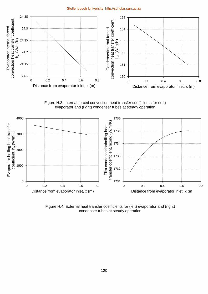
120
24.1
24.15
24.2
24.25
24.3
24.35
0 0.2 0.4 0.6 0.8
Eva
pora
tor
inte
rnal
forc
ed
conv
ectio
n he
at tr
ansf
er c
oeff
icie
nt,
h ei(W
/m2 K
)
Distance from evaporator inlet, x (m)
150
151
152
153
154
155
0 0.2 0.4 0.6 0.8
Con
dens
erin
tern
al fo
rced
co
nvec
tion
heat
tran
sfer
coe
ffic
ient
, h c
i(W
/m2 K
)
Distance from evaporator inlet, x (m)
0
1000
2000
3000
4000
0 0.2 0.4 0.6 0.8
Eva
pora
tor
boili
ng h
eat t
rans
fer
coef
ficie
nt, h
b(W
/m2 K
)
Distance from evaporator inlet, x (m)
1731
1732
1733
1734
1735
1736
0 0.2 0.4 0.6 0.8
Film
con
dens
atio
nboi
ling
heat
tr
ansf
er c
oeff
icie
nt, h
cond
(W
/m2 K
)
Distance from evaporator inlet, x (m)
Figure H.3: Internal forced convection heat transfer coefficients for (left) evaporator and (right) condenser tubes at steady operation
Figure H.4: External heat transfer coefficients for (left) evaporator and (right) condenser tubes at steady operation
Stellenbosch University http://scholar.sun.ac.za