Effect of Thermo-Mechanical Treatment on Texture Evolution ...
Paper ID #9027
Development and evolution of a new mechanical design laboratory course
Dr. Steven P Marra P.E., Johns Hopkins University
Steven P. Marra received his B.S. degree from the University of Pittsburgh in 1993, and his M.S. andPh.D. degrees from The Johns Hopkins University, Baltimore, MD, in 1998 and 2001, respectively, allin mechanical engineering. He is currently a Senior Lecturer in mechanical engineering at The JohnsHopkins University. His research interests include soft and hard tissue biomechanics, nonlinear mechanicsof solids, mechanics of tissue damage, and undergraduate engineering education.
c©American Society for Engineering Education, 2014
Page 24.408.1

Development and evolution of a new mechanical design
laboratory course
Abstract A new sophomore-level mechanical design laboratory course was developed two years ago at
Johns Hopkins University to support a required lecture course entitled Mechanics Based Design.
The laboratory course was created because students requested more instruction about machine
components and they desired additional hands-on design experiences. The laboratory course is
structured into three components which build on each other throughout the semester. Lectures,
given every one to two weeks, introduce the students to various machine components,
terminology, standards, and design tools and methodologies. Laboratories, also scheduled every
one to two weeks, provide the students with opportunities to apply the lecture material to real
machine components and systems and to develop practical skills in design and machining. Each
laboratory includes three separate activities for the students to perform, and almost all of the
laboratory equipment was designed and constructed in-house specifically for the course. The
third component of the course is a design project, which is assigned at the beginning of the
semester and requires the students to integrate what they learn from the weekly lectures and
laboratories, in addition to the material they learn in the Mechanics Based Design lecture course.
The students work in small teams to design and build a mechanical device to meet a set of
performance and budget specifications. The devices are tested at the end of the semester and the
students submit a design report for evaluation.
The mechanical design laboratory course was added to the curriculum in the Spring of 2012 and
included five lecture topics and five laboratories. The subjects of these lectures and laboratories
included screws and threaded fasteners, bearings, gears, pressure vessels, fits and tolerances,
finite element modeling, and mechanical failure. Additional lectures and laboratories were added
in 2013, including two laboratories at the start of the semester in which the students learn how to
operate a milling machine and a lathe. Subsequent laboratories require the students to use one of
these machines to fabricate a component of their design for a specific activity. Additional
changes were made for the 2014 course offering, including a new laboratory on belt and chain
drives, and a new design project.
Background A new one-credit mechanical design laboratory course was developed two years ago at Johns
Hopkins University. Prior to this, all sophomore-level mechanical engineering students were
required to take a four-credit course during the Spring semester entitled Mechanics Based
Design, which included a laboratory component. The students taking this course had some
strength-of-materials knowledge from a previous required course. This knowledge included
stresses in beams and in circular cylinders under torsion. The Mechanics Based Design course
built upon and extended this knowledge with coverage of deflections, three-dimensional stresses
and strains, stress concentrations, elastic constitutive laws, yielding, column buckling, basic
fracture mechanics, and fatigue failure. The laboratory component, however, involved mostly
theoretical modeling and mechanical testing of structures, with little “hands-on” experience for
the students. Further, the amount of material that had to be covered in the fourteen-week
Page 24.408.2
semester meant that the students had very little exposure to machine components, and no actual
design experience.
This deficiency, as articulated by the students in their course evaluations and senior exit-
interviews and recognized by the mechanical engineering faculty, was addressed in 2012 by
splitting the original 4-credit Mechanics Based Design course into one 3-credit Mechanics Based
Design lecture course and one, new and separate, 1-credit Mechanics Based Design Laboratory
course. The laboratory course was taught by a separate instructor and was designed to support,
but be independent of, the lecture course.
The new Mechanics Based Design Laboratory course is located in a 1000 ft2 room next to
several other mechanical engineering undergraduate laboratories on campus. A working, but
antiquated, hydraulically-driven tension/compression testing machine (MTS Systems
Corporation) was already available in the room, but it had a very poor user interface and no data-
acquisition system. Despite these shortcomings, the machine was used in 2012 and 2013 for
several laboratory activities. In addition to the laboratory space, a startup budget of $30k was
provided by the Johns Hopkins University Whiting School of Engineering to develop the
laboratory facilities.
The laboratory course is composed of three separate components which build on each other
throughout the semester: lectures, guided laboratory activities, and a design project. Changes
were made to each of these components when the course was taught for the second time in 2013,
and additional changes were made for the 2014 course. The lecture topics, laboratory activities,
and design projects will be described shortly.
It should be noted that the average class size for the course is 60 students, and that most of the
students have had no prior machining training (e.g. how to use a milling machine) and have not
yet gained any computer-aided design (CAD) skills.
It should also be noted that Nagurka and Anton recently published a similar paper on their
experiences developing a new junior-level machine design laboratory at Marquette University.1
It is hoped that the work presented here will provide additional insights for others who may be
developing similar laboratories.
Lecture topics
Lectures are given every one or two weeks and cover the background material needed for the
upcoming laboratory activities and for the design project. Each 50-minute lecture includes a
mixture of conceptual (e.g. stresses on a gear tooth) and practical (e.g. how to specify a thread
size on a drawing) knowledge. Many of the lecture topics build upon material presented in the 3-
credit lecture course, but it is not critical that the two courses be synchronized. In addition to
basic course and safety information, the following topics are covered.
Screws and Threaded Fasteners, including:
• Terminology
• Thread identification conventions
• Tap and clearance hole sizes
Page 24.408.3

• Relationship between tightening torque and developed axial force
• Bolt preload
• Thread stripping
• Design considerations for threaded fasteners
• Shear loading of bolts
• Power screws
Bearings, including:
• Lubrication regimes
• Sleeve bearing selection
• Journal bearings
• Roller element bearings – terminology, kinds, and performance differences
• Bearing failure and life calculations
• Design considerations for bearings
Gears, including:
• Types of gears
• Gear terminology and definitions
• Backlash and interference
• Contact ratio
• Torques and forces on spur and worm gears
• Gear failure
• American Gear Manufacturing Association analysis of bending stress, contact
stress, and fatigue strength of spur gear teeth.
• Gear train design
• Worm gear efficiency
Belt and chain drives, including:
• Standard styles of belts and drive chains
• Comparison of belt, chain, and gear drives
• Friction drive equations (initial tension, transmitted torque, etc.)
• Standard methods of maintaining belt tension
• Chain chordal action
• Design considerations for belt and chain drives
• Friction losses in belt drives
Fits and tolerances, including:
• Classifications of fits
• Hole basis vs. shaft basis
• Calculating and indicating tolerances
• Relationship between press-fit interference and holding force/torque
Shaft whirl, including:
• Derivation of inherent critical shaft speed
• Effect of added loads on critical shaft speed
Page 24.408.4

A lecture is also presented to introduce the students to the finite element method. This lecture
does not support any particular lab activity, but is it believed that all mechanical engineering
students should be aware of this powerful, and too often improperly used, tool. Possible topics
for future lectures include hydraulic and pneumatic systems, linkages, and digital image
correlation (DIC) for measuring strain.
Guided laboratory activities
Laboratories are scheduled every one to two weeks and provide the students with opportunities
to apply the lecture material to real machine components and systems and to develop practical
skills in design and machining. Five separate student lab sections were offered to students in
2012 and 2013. Six sections were offered in 2014 in order to limit the number of students in each
section to no more than 12. Each lab section was scheduled for 1 hour and 20 minutes in 2012.
This amount of time was found to be too short to complete all of the activities planned for each
lab, so the lab times were increased to 1 hour and 50 minutes in 2013.
Students receive a handout at the start of each laboratory which guides them through the various
activities they must perform. Each laboratory session includes three activities, and the students
rotate through them in groups of 3-4 students. As they work through each activity, they must fill
in sections of the handout with measurements, calculations, drawings, short answers, and
comments. The completed handouts are returned at the end of the lab to be graded. There are no
lab reports, and no homework is assigned.
The guided laboratory activities are designed to provide the students with several deliverables,
including:
• familiarity with various common machine components through hands-on experiments
• practical applications of the material presented in the Mechanics Based Design
lecture course
• appreciation of the limitations of theory
• preparation for the senior-level capstone design project course
• experiences in decision making, design, and basic machining
In order to better provide for the last bullet-point above, a new miniature mill and miniature lathe
were added to the laboratory in 2013. The mill is a MicroLux High Precision Heavy Duty R8
Miniature Milling Machine, and the lathe is a MicroLux 7x16 Mini Lathe (Micro-Mark). The
students learn how to use these machines in the first two laboratories of the semester, and are
then expected to use them in subsequent laboratories and for their design project. Before leaving
the first laboratory, each student must mill the edge of an acrylic plate and drill a hole through
the plate in a specified location. Before leaving the second laboratory, each student must face,
turn, and part a Delrin rod using the lathe.
Another significant change from the original course offering is that the MTS testing machine was
replaced in 2014 with a new tension/compression testing machine from Applied Test Systems
(ATS). This new machine will enable the students to perform a wider range of experiments and
analyses.
The topics and activities of the following laboratories are described below.
Page 24.408.5

Threaded fasteners and power screws laboratory
Bolt failure activity – In this simple experiment, students tighten brass bolts until failure
occurs. Spacers of different lengths are used to vary the number of threads engaged, so
both thread stripping and bolt shear-off can be observed. Students also explore the
relationship between applied tightening torque and bolt tension using a Skidmore-
Wilhelm bolt tester.
Design and fabrication of a shear failure plate – Each group of students was given an
acrylic plate containing a hole at one end. The plate fits in a specially designed fixture in
the ATS testing machine such that it can rotate about the hole when an upward force is
applied to the other end (see Figure 1). The students must determine the location of a hole
in the plate for a (stationary) 4-40 screw such that shear failure of the screw will occur
within a specified range of applied force. The students then drill and tap the hole using
the milling machine and test the plate to determine if they calculated the correct hole
location.
Concepts applied and experiences gained: statics (forces and moments), stress analysis
and failure, safety factors, practice using a mill to machine a hole in a precise location,
tapping a hole.
Figure 1 – Acrylic plate and testing fixture for bolt failure plate activity.
Analysis of a jack screw – Two jack screws, one dry and one greased, are mounted on
(separate) bases and loaded with 100 pounds on each (see Figure 2). Students rotate the
jack screw nut by pushing or pulling on the end of an aluminum moment arm which has
been instrumented with strain gauges. The torques required to raise and lower the loads
are calculated from the geometry and Young’s modulus of the moment arm and from the
measured strains. The students use these measurements to compute the efficiency and
friction coefficient of each jack screw.
Concepts applied and experiences gained: statics (forces and torques), beam bending,
efficiency, strain gauges, data acquisition and LabView®.
Page 24.408.6

Figure 2 – Jack screw and moment arm
An activity in which students loaded a bolted joint to failure was tried once in 2012, but it
did not deliver a sufficient amount of knowledge or experience to the students.
Bearings laboratory
Design of a torsion rod – In this experiment the students use the lathe to machine a 3/8-
inch diameter Delrin rod so that it will fit between two ball bearings. The rod is placed in
a specially designed fixture and a known torque is applied to one end of the rod using
hanging weights (see Figure 3). The fixture can accommodate a range of rod lengths. The
students must calculate the correct length of the Delrin rod such that a specified angle of
twist is obtained when a known torque is applied.
Concepts applied and experiences gained: statics, strength of materials (torsion and angle
of twist), practice using a lathe, exposure to various kinds of bearings (roller ball, sleeve,
and linear).
Figure 3 – Torsion rod fixture
Page 24.408.7
Sleeve bearing performance activity – This is the first of several activities to use a 10-
inch variable speed wood lathe (PSI Woodworking). This lathe has a ¾ hp motor, a
digital speed display, and can run at speeds from 150-3000 rpm. A ½-inch diameter steel
shaft is mounted in the lathe chuck for this activity. A sleeve bearing is placed over the
shaft and a known lateral load is applied to the bearing using weights. A variable DC
power supply is used to run the lathe motor, and the current to the motor is monitored
using LabView®. The relationship between the motor output torque and the current is
provided to the students. The students investigate how load and rpm affect the
performance of the bearing by measuring the torque required to maintain a constant
speed. Students compare the performance of solid bronze bearings, with and without
lubrication.
Concepts applied and experiences gained: bearing friction, relationships between voltage
and speed and between current and torque for a simple dc motor.
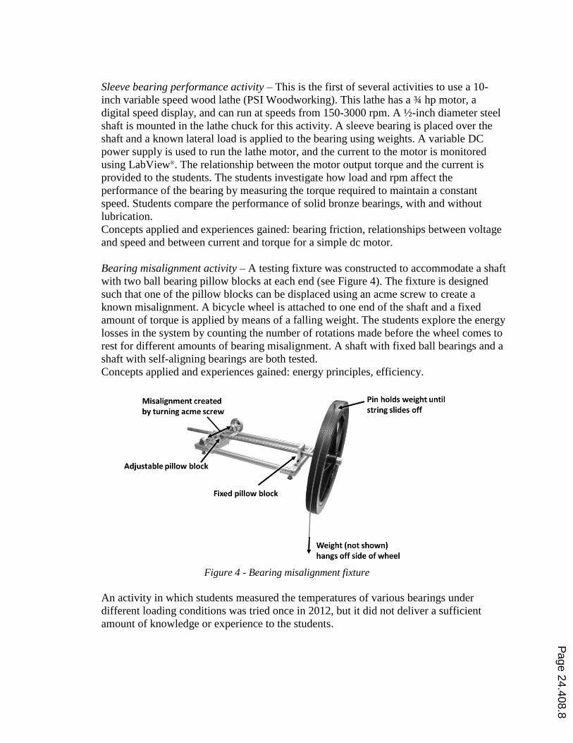
Bearing misalignment activity – A testing fixture was constructed to accommodate a shaft
with two ball bearing pillow blocks at each end (see Figure 4). The fixture is designed
such that one of the pillow blocks can be displaced using an acme screw to create a
known misalignment. A bicycle wheel is attached to one end of the shaft and a fixed
amount of torque is applied by means of a falling weight. The students explore the energy
losses in the system by counting the number of rotations made before the wheel comes to
rest for different amounts of bearing misalignment. A shaft with fixed ball bearings and a
shaft with self-aligning bearings are both tested.
Concepts applied and experiences gained: energy principles, efficiency.
Figure 4 - Bearing misalignment fixture
An activity in which students measured the temperatures of various bearings under
different loading conditions was tried once in 2012, but it did not deliver a sufficient
amount of knowledge or experience to the students.
Page 24.408.8

Gears laboratory
Gear tooth stress visualization – A pair of large (0.55 pitch) spur gear teeth were
machined from a 0.5 inch thick sheet of polycarbonate and mounted on a clear acrylic
base (see Figure 5). The base was designed so that the teeth can mesh by sliding the gears
in opposite directions (clockwise or counter-clockwise). The effective center distance
between the gears is adjustable so that backlash can be observed. Polycarbonate is a
photoelastic material, so the students are able to observe the contact stresses during
meshing by placing the gears between two circular polarizing filters and illuminating
them from behind with a light box. By tracing the point of contact as the teeth mesh, the
students can determine the pressure angle of the gears.
Concepts applied and experiences gained: photoelasticity, contact stress, stress
concentrations (at roots of gear teeth).
Figure 5 – Gear tooth stress visualization setup with photoelastic gears
Gear train design and analysis – Students are provided with a set of 10 acrylic spur
gears, all with the same pitch and pressure angle. The number of teeth on each gear
ranges from 30 to 120. The students must first determine which four gears can be
combined to create a gear train with a specified ratio. The students must then to use the
mill to drill holes in two acrylic bars to accommodate the gears (see Figure 6). The holes
must have the correct spacing between them, otherwise the gears will not mesh well. The
efficiency of the gear train is determined by hanging weights off of the sides of the input
and output shafts.
Concepts applied and experiences gained: efficiency, practice using the milling machine.
Page 24.408.9

Figure 6 – Gear train fixture
Worm gear box analysis – A used worm gear box was purchased on ebay.com and
dismantled. The internal components were remounted in a clear acrylic case so that the
students can see the worm and worm gear meshing (see Figure 7). A known weight hangs
off the side of the output shaft. Students add weights to the side of the input shaft until
the output shaft starts to rotate. The efficiency of the worm gear box is then calculated
from the values of the two weights. The axial force on the worm is also measured using a
load cell.
Concepts applied and experiences gained: efficiency, load cells, data acquisition, heat
transfer (students are asked to inspect the original gear box house and explain the purpose
of the fins).
Figure 7 – Worm gear box in clear acrylic case
Belt and chain drives laboratory (added in 2014)
Timing belt drive speeds and torques – Two motors are connected via a timing belt and
sprockets (see Figure 8). One motor acts as the driver and provides the power to turn the
other motor (the load). Tachometers display the speed of each motor. The students are
Page 24.408.10

provided with the torque-speed curve for the driving motor and asked to investigate the
response of the system to various sprocket ratios. Students learn about the relationships
between torque, speed, load, and operating point of a motor.
Figure 8 – Timing belt drive apparatus
Chain drive vibrations – Two sprockets are connected via a roller chain (see Figure 9). A
variable-speed motor drives one of the sprockets. The tension in the chain is adjustable
and it is measured using a load cell. The students set the chain tension to specific values
and then increase the drive speed until the chain vibrations reach a maximum. They then
compare the actual critical speeds (measured with a hand-held tachometer) at various
tensions with the theoretical values.
Concepts applied and experiences gained: chordal action of roller chain drives, vibrations
and resonance, load cells and data acquisition, use of a hand-held tachometer.
Figure 9 – Timing belt drive apparatus
Stress concentrations and failure laboratory
Stress concentration visualization – A pneumatically driven tensile testing machine was
constructed to accommodate ¼-inch thick 3-inch wide polycarbonate dog-bone
specimens. Three different specimens were fabricated, each with a different stress
concentration (circular hole, elliptical hole, and circular notches). A light box and circular
polarizing filters allow the students to see the regions of high stress in the photoelastic
specimens. The students calculated the maximum stresses in each specimen from the
tensile forces (measured with a load cell) and using standard graphs of stress-
concentration factors.
Concepts applied and experiences gained: pneumatics, photoelasticity, stress analysis.
Page 24.408.11

Buckling activity – Each group of students is given one round brass rod with flat ends and
one square aluminum rod with rounded ends. The rods are both approximately 12 inches
in length and 1/8 inch wide. The rods are placed in a specially designed loading fixture
between two plates (only one rod is tested at a time). The plates have round holes to
accommodate the brass rod, creating effectively fixed end conditions in this rod, and
grooves to accommodate the aluminum rod, creating effectively pinned end conditions in
this rod. Weights are added to the upper plate until the rod buckles. The students compare
the theoretical critical buckling loads to the actual buckling loads.
Concepts applied and experiences gained: safety factors, materials science.
Fatigue testing activity – A fixture was constructed to convert the wood lathe into a
replica of the classic R.R. Moore rotating-beam fatigue-testing machine (see Figure 10).
The fixture contains four stationary bearings and two central “floating” bearings. A ¼-
inch diameter steel shaft is placed in the bearings, with one end clamped in the lathe
chuck. The region of the shaft between the two floating bearings contains a narrower 1/8-
inch diameter section. The shaft is rotated at 3,000 rpm while a constant load pulls down
on the floating bearings. Students predict the number of cycles to fatigue failure and
compared this with the actual result.
Concepts applied and experiences gained: beam bending, stress concentrations,
reliability.
Figure 10 – Fatigue testing apparatus
Various activities laboratory
This laboratory is composed of activities that do not fit into a single “theme.”
Thin-walled pressure vessel activity – An empty 12-oz soda can is modeled as thin-
walled pressure vessel. The can is instrumented with two strain gauges to measure the
hoop and circumferential strains. The can is mounted in a specially designed fixture (see
Figure 11) and pressurized using a bicycle tire pump. The internal pressure is measured
with a pressure gauge. The students calculate the hoop and circumferential stresses in the
pressurized can from their strain measurements. They also compare the theoretical
Page 24.408.12

internal pressure, calculated from the strains and the geometry and material properties of
the can, with the measured internal pressure.
Concepts applied and experiences gained: multiaxial stress-strain relations, strain gauges,
proper use of a micrometer.
Figure 11 – Thin-walled pressure vessel apparatus
Press-fits activity – Students are given a one-inch diameter steel shaft and hubs made
from different materials and with different hole diameters. The students feel the
difference between a free-running fit and a sliding fit. They then use an arbor press to
create an interference fit. The students then use the lathe to machine an undersized bore
in a PVC hub, through which a steel pin is pressed. The ATS machine is used to measure
the force required to push the pin through the hub. The measured force is compared with
the theoretical value.
Concepts applied and experiences gained: tolerances, mechanics of thick-walled pressure
vessels, proper use of an arbor press, practice using the lathe.
Shaft-whirling activity – This activity was added in 2013. A ¼-inch diameter steel shaft is
clamped at one end in the wood chuck lathe, and the other end is supported by a bearing
mounted in a ball-joint (see Figure 12). The students calculate the inherent critical speed
of the shaft. They then increase the rpm of the shaft until it starts to whirl, and compare
the actual critical speed with their calculation. They then repeat the calculation and the
experiment with a shaft collar attached at the center of the shaft.
Concepts applied and experiences gained: beam bending, stability, resonance.
Figure 12 – Shaft-whirl apparatus
Page 24.408.13

Design project
The third component of the course is a design project. This project requires the students to
integrate what they learn from the weekly lectures and laboratories, in addition to the material
they learn in the Mechanics Based Design lecture course. The project was assigned to the
students at the half-way point in the semester in 2012 (immediately after Spring-break). In 2013
and 2014, it was assigned during the second week of classes to give the students more time to
think about it and to help them better appreciate the material covered in the laboratories. Teams
of two or three students work together to complete the project.
The project assigned for 2012 and 2013 required the students to design and construct a small
wind turbine. Each team was given a model airplane propeller and an 8-inch 8-inch ¼-inch
sheet of acrylic. Each team could purchase an additional $15 worth of parts for their device. A dc
motor was provided for the generator. The students were given performance curves for the motor
and the propeller. The wind turbines were tested in a small wind tunnel located on campus, and
they had to be designed to fit within the tunnel test section. The students were given full access
to the mill and lathe, and were also given training on how to use the laser cutter. One of the wind
turbine designs in shown in Figure 13.
Figure 13 – A student-engineered wind turbine
Each team submitted a design report at the end of the semester. The reports included drawings,
calculations, descriptions of the wind-turbine design with justifications for all decisions and
assumptions, a cost analysis, and a performance analysis. Each team was also required to meet
with the instructor twice during the semester to review their progress.
The wind turbine project was successful in that it provided the students with an opportunity to
work through the design process and to experience the consequences of their design decisions. In
retrospect, however, the project did not require the students to use enough of the knowledge they
had learned. Because the wind forces on the turbine structures were relatively small, there was
no real concern that any parts would suffer a mechanical failure. As a result, there was little need
for the students to perform calculations when designing their structures. Most of the design
decisions involved selecting components for the power transmission and determining their
locations.
Page 24.408.14

A new design project was assigned in 2014. This project required the students to design and
construct a crane with a boom to raise a 10-pound load using a small dc motor. Design
constraints included a limit on the allowable deflection of the boom and a budget not to exceed
$15 per group. Results of this project will be presented at the 2014 ASEE Annual Conference.
Final remarks
When the Mechanics Based Design Laboratory course was first developed in 2012, assessment
tools were not included in the curriculum to provide information on the effectiveness of the
course. Anecdotal comments from the students and from the teaching assistances (several of
whom had taken the four-credit course prior to 2012) indicate that the laboratory course is
delivering the hands-on experiences and the machine design instruction that was missing prior to
its inception.
Reference 1 Nagurka and Anton, “Discovery learning experiments in a new machine design laboratory,” Proceeding
from the 2013 ASEE Annual Conference, Atlanta, GA, 2013.
Page 24.408.15