DETERMINATION OF THE ‘DUCTILE TO BRITTLE TRANSITION ... 4 Issue 2.pdf · The Ductile-to-Brittle...
15
NOVATEUR PUBLICATIONS INTERNATIONAL JOURNAL OF INNOVATIONS IN ENGINEERING RESEARCH AND TECHNOLOGY [IJIERT] ISSN: 2394-3696 VOLUME 4, ISSUE 2, Feb.-2017 27 | Page DETERMINATION OF THE ‘DUCTILE TO BRITTLE TRANSITION TEMPERATURE OF VARIOUS METALS MR. PATIL VISHAL BALASO Lecturer, Sant Tukaram Polytechnic, Indori, Maharashtra, India MR. RELEKAR KEDAR MADANRAO Lecturer, Sant Tukaram Polytechnic, Indori, Maharashtra, India MR. MOHITE DIGVIJAY MOHANKUMAR Lecturer, D.Y. Patil college of engineering & Polytechnic, Talsande, Maharashtra, India ABSTRACT The Ductile-to-Brittle Transition Temperature (DBTT) is a phenomenon that is widely observed in metals. Below critical temperature (DBTT), the material suddenly loss ductility and becomes brittle. The controlling mechanism of this transition still remains unclear despite of large efforts made in experimental and theoretical investigation. All ferrous materials (except the austenitic grades) exhibit a transition from ductile to brittle when tested above and below a certain temperature, called as Transition Temperature. The project deals with the determination of the ‘Ductile to Brittle Transition Temperature of various metals. Work carried out in this project is purchasing the material followed by test specimen preparation. The specimens then keep in the liquid nitrogen for cooling for soaking time of 15 min. Then the actual charpy impact testing of the specimens at variable temperature ranging are carried out in controlled atmosphere. The readings taken are the impact energy (joules) of specimen at specific temperature. The graph of energy absorbed vs temperature is plotted to get the range of transition temperature. The transition temperature range determined for various metals is as below Stainless steel of 304grade- Regular mild steel square rods Aluminum INTRODUCTION NEED TO DETERMINE TRANSITION TEMPERATURE AND COMPARING Why should steel that is normally capable of sustaining great loads and capable of ductility greater than 20 percent suddenly, when cold, become so brittle so brittle that it could be shattered a minor blow or similar impact? This was this was the question asked over a hundred years ago when fracture occurred in steel structures in severe structures in severe weather. Since then many similar failure have been documented. There are number of possible reasons for such failures: Fatigue. Corrosion. Fabrication. Design errors. Poor quality steel. The most dramatic and unexpected cause of brittle failure in ferrous alloys is their tendency to loose almost all of their toughness when the temperature drops below their ductile to brittle transition temperature. This has been the cause for numerous dramatic and catastrophic failures: i.e. the rupture of a 2.3 million gallon molasses storage tank in the winter of 1911. Bridge failures. Liberty ships breaking in half in the harbor and at sea during World War II.
Transcript of DETERMINATION OF THE ‘DUCTILE TO BRITTLE TRANSITION ... 4 Issue 2.pdf · The Ductile-to-Brittle...

NOVATEUR PUBLICATIONS
INTERNATIONAL JOURNAL OF INNOVATIONS IN ENGINEERING RESEARCH AND TECHNOLOGY [IJIERT]
ISSN: 2394-3696
VOLUME 4, ISSUE 2, Feb.-2017
27 | P a g e
DETERMINATION OF THE ‘DUCTILE TO BRITTLE TRANSITION
TEMPERATURE OF VARIOUS METALS MR. PATIL VISHAL BALASO
Lecturer, Sant Tukaram Polytechnic, Indori, Maharashtra, India
MR. RELEKAR KEDAR MADANRAO Lecturer, Sant Tukaram Polytechnic, Indori, Maharashtra, India
MR. MOHITE DIGVIJAY MOHANKUMAR
Lecturer, D.Y. Patil college of engineering & Polytechnic, Talsande, Maharashtra, India ABSTRACT The Ductile-to-Brittle Transition Temperature (DBTT) is a phenomenon that is widely observed in metals. Below critical temperature (DBTT), the material suddenly loss ductility and becomes brittle. The controlling mechanism of this transition still remains unclear despite of large efforts made in experimental and theoretical investigation. All ferrous materials (except the austenitic grades) exhibit a transition from ductile to brittle when tested above and below a certain temperature, called as Transition Temperature. The project deals with the determination of the ‘Ductile to Brittle Transition Temperature of various metals.
Work carried out in this project is purchasing the material followed by test specimen preparation. The specimens then keep in the liquid nitrogen for cooling for soaking time of 15 min. Then the actual charpy impact testing of the specimens at variable temperature ranging are carried out in controlled atmosphere. The readings taken are the impact energy (joules) of specimen at specific temperature. The graph of energy absorbed vs temperature is plotted to get the range of transition temperature. The transition temperature range determined for various metals is as below
Stainless steel of 304grade- Regular mild steel square rods Aluminum
INTRODUCTION NEED TO DETERMINE TRANSITION TEMPERATURE AND COMPARING
Why should steel that is normally capable of sustaining great loads and capable of ductility greater than 20 percent suddenly, when cold, become so brittle so brittle that it could be shattered a minor blow or similar impact? This was this was the question asked over a hundred years ago when fracture occurred in steel structures in severe structures in severe weather. Since then many similar failure have been documented. There are number of possible reasons for such failures:
Fatigue. Corrosion. Fabrication. Design errors. Poor quality steel.
The most dramatic and unexpected cause of brittle failure in ferrous alloys is their tendency to loose almost all of their toughness when the temperature drops below their ductile to brittle transition temperature. This has been the cause for numerous dramatic and catastrophic failures: i.e. the rupture of a 2.3 million gallon molasses storage tank in the winter of 1911. Bridge failures. Liberty ships breaking in half in the harbor and at sea during World War II.

NOVATEUR PUBLICATIONS
INTERNATIONAL JOURNAL OF INNOVATIONS IN ENGINEERING RESEARCH AND TECHNOLOGY [IJIERT]
ISSN: 2394-3696
VOLUME 4, ISSUE 2, Feb.-2017
28 | P a g e
ACCIDENTS HAPPENED IN INDIAN NAVY (Source:- http://en.wikipedia.org/wiki/List_of_Indian_Naval_accidents)
January 2011: INS Vindhyagiri (F42), a Nilgiri-class frigate, capsized after a collision with a Cyprus-flagged merchant vessel MV Nordlake near the Sunk Rock light house, following which a major fire broke out in the ship's engine and boiler room. Everyone on board was evacuated as soon as the fire broke out and hence there were no casualties. INS Vindhyagiri was later decommissioned.
August 2013: Blasts ripped through the torpedo compartment of the INS Sindhurakshak (S63) while it was berthed at the naval dockyard off the Mumbai coast. Fifteen Sailors and three officers were killed. Other sources state that a small explosion occurred around midnight which then triggered the two larger explosions. The disaster was thought to be the Indian navy's worst since the sinking of the frigate INS Khukri by a Pakistani submarine during the 1971 war.
December 2013: INS Konkan (M72), a Pondicherry-class minesweeper under the Eastern Naval Command, caught fire at the naval dockyard at Visakhapatnam while undergoing repairs. The fire engulfed much of the ship's interior before it was put off. No casualties were reported.
December 2013: In the second incident in the same month, INS Talwar (F40), the lead ship of the Talwar class frigate of the Indian Navy, collided with a fishing trawler injuring four of the 27 people on board the trawler and sinking it. The fishing trawler was operating without lights. The captain of the ship was subsequently stripped of command.
December 2013: In the third incident in the same month, INS Tarkash (F50), again a Talwar class frigate, suffered damage to its hull when it hit the jetty while docking at the Mumbai naval base. The navy ordered a board of inquiry..
January 2014: INS Betwa (F39), an indigenously built Brahmaputra class guided missile frigate, ran aground and collided with an unidentified object while approaching the Mumbai naval base. The sonar system of the frigate was cracked, leading to faulty readings and an ingress of saltwater into sensitive equipment.
January 2014: In the second incident in the same month, INS Vipul (K46), a veer class corvette of the elite 22nd Killer Missile Vessel Squadron, was detected with a hole in its pillar compartment which forced the ship back into the harbor while it was on an operational deployment.
February 2014: On 3 February, INS Airavat (L24), a Shardul class amphibious warfare vessel, ran aground while returning to its home base at Visakhapatnam, causing slight damage to its propellers. Following the incident, its commanding officer, Captain JPS Virk, was relieved of command pending the findings of a Board of Inquiry.
February 2014: On 26 February, INS Sindhuratna (S59), a Kilo-class submarine, had a fire detected on board when trials were being conducted which resulted in smoke leading to suffocation and death of two officers. Seven sailors were reported injured and were airlifted to the naval base hospital in Mumbai. According to the naval board of inquiry, the fire was caused due to problems in the cables of the vessel. This particular incident led to the resignation of Chief of Naval Staff (CNS) Admiral D K Joshi on 26 February 2014, who owned moral responsibility for the incidents in the past few months.
For the above mentioned and such similar problem it becomes necessary to find out at what temperature the transition occurs and which material is best to use at cold atmosphere or at polar region. i.e. the material loses its toughness and ductility and loses its strength. The proposed project deals with finding out transition temperature and comparing strength of following material below room temperature and also below zero degree temperature.
Stainless steel of 304 grade Mild Steel Aluminum.

NOVATEUR PUBLICATIONS
INTERNATIONAL JOURNAL OF INNOVATIONS IN ENGINEERING RESEARCH AND TECHNOLOGY [IJIERT]
ISSN: 2394-3696
VOLUME 4, ISSUE 2, Feb.-2017
29 | P a g e
LITERATURE SURVEY
1. B. Tanguy, J. Bensson R. Piques A.Pineau “Ductile to Brittle Transition of an A508 Steel Characteristics by
Charpy Impact Test Part: I Experimental Result”: - This study is devoted to the ductile–brittle transition behavior of a French A508 Cl3 (16MND5) steel. Due to its importance for the safety assessment of PWR vessels, a full characterization of this steel with Charpy V-notch test in this range of temperature was undertaken. The aim of this study is to provide a wide experimental database and micro structural observations to supply, calibrate and validate models used in a local approach methodology. Mechanical and fracture properties of the steel have been investigated over a wide range of temperatures and strain rates. Effects of impact velocity on ductile–brittle transition curve, on ductile tearing and on notch temperature rise are presented and discussed.
2. Dr. Aniruddha moitra Material Technology Division “Study of Ductile-Brittle Transition Temperature of 9Cr-1Mo Steels” :- Defining the ductile to brittle transition temperature (DBTT) below which catastrophic failures occurring in structures made of ferritic steels is a major technological challenge for designers. Generally practiced empirical approaches (ASME K Curve) to predict the fracture toughness over the DBTT regime fail to appreciate the scatter, originating from the random distribution of cleavage crack initiation sites, and often lead to ultra-conservative predictions.
3. Alexande C. Edrington, Illinois institute of technology “Effect Of Intermediate Precipitation Treatments On
The Temperature Embrittlement Of 4140 Forging- Grade Steel” :- Temper Embrittlement of martensitic steel occurs after a heat treatment or cooling cycle through temperature range 300-600ºc .The appearance of this embrittlement phenomena often manifests itself trough an increase in the ductile-to-brittle transition temperature of the steel as determined through Charpy V-Notch testing . This study investigate effect of heat treatment on advent of reverse temper Embrittlement 4. M.L. Hamilton and P.H.Jones Effect Of Heat Treatment And Test Method On DBTT Of V-5Cr-5Ti Alloy Steel : Specimens annealed at 1125"C for 1 h and furnace cooled were brittle at room temperature (RT) and experienced a mixture of intergranular and cleavage fracture. Fracture toughness (JIQ) at RT was 52 kJ/m2
and the Charpy-V impact fracture energy (IFE) on one-third scaled specimens was 0.2 J. While material exhibited high fracture toughness at 100°C (JIQ was 485 kJ/m2) and did not fracture during an impact test, the fracture surface contained a mixture of dimple and intergranular fracture, with intergranular fracture making up 40% of the total fracture surface.
DBTT AND METALLOGRAGHY 2.1 FRACTURE MECHANISMS At higher temperatures the yield strength is lowered and the fracture is more ductile in nature. On the opposite end, at lower temperatures the yield strength is greater and the fracture is more brittle in nature. This relationship with temperature has to do with atom vibrations. As temperature increases, the atoms in the material vibrate with greater frequency and amplitude. This increased vibration allows the atoms under stress to slip to new places in the material (i.e. break bonds and form new ones with other atoms in the material). This slippage of atoms is seen on the outside of the material as plastic deformation, a common feature of ductile fracture. When temperature decreases however, the exact opposite is true. Atom vibration decreases, and the atoms do not want to slip to new locations in the material. So when the stress on the material becomes high enough, the atoms just break their bonds and do not form new ones. This decrease in slippage causes little plastic deformation before fracture. Thus, we have a brittle type fracture.

NOVATEUR PUBLICATIONS
INTERNATIONAL JOURNAL OF INNOVATIONS IN ENGINEERING RESEARCH AND TECHNOLOGY [IJIERT]
ISSN: 2394-3696
VOLUME 4, ISSUE 2, Feb.-2017
30 | P a g e
At moderate temperatures (with respect to the material) the material exhibits characteristics of both types of fracture. In conclusion, temperature determines the amount of brittle or ductile fracture that can occur in a material. Another factor that determines the amount of brittle or ductile fracture that occurs in a material is dislocation density. The higher the dislocation density, the more brittle the fracture will be in the material. The idea behind this theory is that plastic deformation comes from the movement of dislocations. As dislocations increase in a material due to stresses above the materials yield point, it becomes increasingly difficult for the dislocations to move because they pile into each other. So a material that already has a high dislocation density can only deform but so much before it fractures in a brittle manner. The last factor is grain size. As grains get smaller in a material, the fracture becomes more brittle. This phenomenon is do to the fact that in smaller grains, dislocations have less space to move before they hit a grain boundary. When dislocations can not move very far before fracture, then plastic deformation decreases. Thus, the material's fracture is more brittle. 2.1.1 BRITTLE FRACTURE Brittle fracture takes place by rapid crack propagation and very little plastic deformation, and yields a relatively flat fracture surface. For most brittle crystalline materials, crack propagation corresponds to the successive and repeated breaking of atomic bonds along specific crystallographic planes, this is known as cleavage. Cleavage is essentially a low temperature phenomenon, which can be eliminated if a sufficiently high deformation temperature is used. See the section on the ductile-to brittle transition. The occurrence of brittle fracture is also associated with certain crystal structures, in particular BCC. 2.1.2 Ductile Fracture The propagation of a ductile crack involves substantial plastic flow and ductile fracture usually gives a characteristic rough fracture surface. Fracture occurs by a process known as microvoid coalescence. First, plastic strain causes small micro voids to form in the material, most often at sites of inclusions. As the process proceeds, these micro voids grow and begin to join together (coalesce). Final failure occurs when the walls of material between the growing voids finally break.
Fig 2.1 Ductile Fracture & Brittle Fracture Phenomenon
2.1.3 Transgranular Versus Intergranular Fracture Crack initiation and propagation are essential to fracture. The manner through which the crack propagates through the material gives great insight into the mode of fracture. In ductile materials (ductile fracture), the crack moves slowly and is accompanied by a large amount of plastic deformation. The crack will usually not extend unless an increased stress is applied. In brittle fracture, cracks spread very rapidly with little or no plastic deformation. The cracks that propagate in a brittle material will continue to grow and increase in magnitude once they are initiated. Another important mannerism of crack propagation is the way in which the advancing crack travels through the material. A crack

NOVATEUR PUBLICATIONS
INTERNATIONAL JOURNAL OF INNOVATIONS IN ENGINEERING RESEARCH AND TECHNOLOGY [IJIERT]
ISSN: 2394-3696
VOLUME 4, ISSUE 2, Feb.-2017
31 | P a g e
that passes through the grains within the material is undergoing trans granular fracture. However, a crack that propagates along the grain boundaries is termed an intergranular fracture. On both macroscopic and microscopic levels, ductile fracture surfaces have distinct features. Macroscopically, ductile fracture surfaces have larger necking regions and an overall rougher appearance than a brittle fracture surface.
Fig 2.2 (A) Highly Ductile Fracture In Which Specimen Necks Down To A Point.
(B) Moderately Ductile Fracture After Some Necking. (C) Brittle Fracture Without Any Plastic Deformation.
2.2 DUCTILE TO BRITTLE TRANSITION TEMPERATURE The ductile-brittle transition is exhibited in bcc metals, such as low carbon steel, which become brittle at low temperature or at very high strain rates. FCC metals, however, generally remain ductile at low temperatures. In metals, plastic deformation at room temperature occurs by dislocation motion. The stress required to move a dislocation depends on the atomic bonding, crystal structure, and obstacles such as solute atoms, grain boundaries, precipitate particles and other dislocations. If the stress required moving the dislocation is too high, the metal will fail instead by the propagation of cracks and the failure will be brittle. Thus, either plastic flow (ductile failure) or crack propagation (brittle failure) will occur, depending on which process requires the smaller applied stress. In fcc metals, the flow stress, i.e. the force required to move dislocations, is not strongly temperature dependent. Therefore, dislocation movement remains high even at low temperatures and the material remains relatively ductile. In contrast to fcc metal crystals, the yield stress or critical resolved shear stress of bcc single crystals is markedly temperature dependent, in particular at low temperatures. The temperature sensitivity of the yield stress of bcc crystals has been attributed to the presence of interstitial impurities on the one hand, and to a temperature dependent Peierls-Nabarro force on the other. However, the crack propagation stress is relatively independent of temperature. Thus the mode of failure changes from plastic flow at high temperature to brittle fracture at low temperature.
Fig 2.3 Ductile to Brittle Transition Graph
The ductile to brittle transition is characterized by a sudden and dramatic drop in the energy absorbed by a metal subjected to impact loading. This transition is practically unknown in fcc metals but is well known in bcc

NOVATEUR PUBLICATIONS
INTERNATIONAL JOURNAL OF INNOVATIONS IN ENGINEERING RESEARCH AND TECHNOLOGY [IJIERT]
ISSN: 2394-3696
VOLUME 4, ISSUE 2, Feb.-2017
32 | P a g e
metals. As temperature decreases, a metal's ability to absorb energy of impact decreases. Thus its ductility decreases. At some temperature the ductility may suddenly decrease to almost zero. This transition is often more abrupt than the transition determined by the energy absorbed. This temperature is called the nil-ductility transition temperature (NDTT). The NDTT is lower than the fracture energy transit ion temperature and is generally more narrowly defined. The difference between these two transition temperatures is related to the high rate of loading during impact testing rate sensitive metals. Increased loading rates cause the yield stress to increase while increasing temperature causes ductility to increase. The fracture energy transition temperature range might not be narrow enough to be able to identify a unique transition temperature. This is often the case for steels. The width of this range varies for different alloys. Fracture in this range is a mixture of ductile and brittle modes of failure. Often criteria other than the energy transition are used to define the transition temperature. One method is to specify a fracture energy below which the material is considered to be brittle. Sometimes the temperature at the halfway point in the transition is regarded as the transition temperature. Another method is to define the ductile to brittle transition in terms of a specified amount of ductile and brittle fracture. For this method the proportion of ductile-brittle fracture is estimated by examining the fracture surface. A 50% ductile-brittle fracture surface is the criteria often used to define the ductile to brittle transition temperature. An examination of a fracture surface will reveal whether fracture occurred by ductile or brittle processes. To the unaided eye a brittle fracture surface has a grainy, salt and pepper appearance. Examination with an SEM clearly reveals the cleavage appearance, river lines and planar micro cracks characteristic of brittle fracture. Brittle fracture can occur inter granularly or trans granularly. Ductile fracture can be recognized by its dull appearance. Ductile fracture is usually Trans granular and its fracture surfaces show a significant amount of plastic deformation between roughly spherical microvoids.
Fig 2.4 A Typical Stress Strain Curve Of Steel.
2.3 CHARPY IMPACT TESTING (V-NOTCH) The Charpy test is a three point bend impact test. It requires a specimen containing a machined notch in the center of the face facing away from the impacting device and a sturdy machine that can impart a sudden load to the specimen. The Charpy tester consists of a heavy pendulum which is allowed to strike the specimen at the bottom of its arch (maximum kinetic energy, maximum velocity). As the specimen deforms and fractures a portion of the kinetic energy of the pendulum is transferred to the specimen. The specimen is broken and the two pieces of the fractured specimen are knocked clear of the testing machine while the pendulum continues its swing to a somewhat lower position than it was released from. The difference in these heights and the mass of the pendulum determines how much energy was absorbed by the specimen. Most impact testers have a gage that reports this energy so that it doesn't have to be computed. Current applications of the Charpy impact test include comparisons of heat to heat variations of steel, evaluation of material behavior during either intentional or accidental high rates of loading, evaluation of the effect of irradiation on the embrittlement of steel, evaluation of the effects of microstructure and fabrication on toughness

NOVATEUR PUBLICATIONS
INTERNATIONAL JOURNAL OF INNOVATIONS IN ENGINEERING RESEARCH AND TECHNOLOGY [IJIERT]
ISSN: 2394-3696
VOLUME 4, ISSUE 2, Feb.-2017
33 | P a g e
and studies of the fundamental aspects of deformation in bcc materials. Together the tensile test and Charpy impact test form a fairly complete evaluation of the mechanical properties of a material. However, it should be noted that the Charpy test is not a simulation of an alloy in service. The results of the Charpy tests are useful indications of how the material might behave in service.
Fig 2.5- A Typical Specimen For V-notch Charpy Test.
The Charpy impact test is a relatively simple, quick and inexpensive method for testing the dynamic fracture behavior of materials. It has been used extensively, particularly on ferrous alloys and has been standardized in ASTM E23. Several of these, plus some additional guidelines are listed below. This list should also provide some insight into the character of the Charpy impact test: • The specimen cannot absorb more than 80% of the maximum energy capacity of the pendulum. • The testing machine must be level and bolted securely to the floor. • Alignment of the striker and the center of the specimen should be checked frequently. • Slop in the axle and bearings should be within specified limits. • The testing machine should be calibrated periodically. Windage and friction should be checked frequently. • Specimen geometry, size, square and especially the acuity of the notch is critical. Variations of 0.005 inches in
the depth of a V-notch can alter the results by 10 joules, almost 10 percent of the impact resistance of a tough material. When conducting a test keep the following things in mind: • The trigger mechanism should permit smooth release of the pendulum. • The broken parts of the specimen must not interfere with the movement of the pendulum. • No more than five seconds can elapse between the time the specimen is removed from then heating or cooling
media until it is correctly seated in the specimen holder and tested. One on the major drawbacks of the Charpy test is that it doesn't provide much information about the fracture process itself. Therefore, instrumented Charpy tests have been developed. A strain gage is mounted on the arm of the pendulum and a fast, triggered data acquisition system records the impact. The data provides load-time profiles that show the different stages of deformation and fracture: general yield, maximum load, fast fracture and arrest load after fast fracture. In addition, the actual energy absorbed can be obtained by accounting for the decrease in velocity of the pendulum as it fractures the specimen. An impact test can be used to assess a material’s fracture resistance. Several such tests have been devised
although in the United States the Charpy Impact Test is the one most widely used. In the Charpy test, a hammer is mounted on a very nearly frictionless pendulum. It is released from a specified height, h, and strikes the sample to be evaluated at the bottom of its arc. When it does so, the material is subjected to a high strain rate, which favors fracture rather than flow. Moreover, the notch on the specimen on the side of the bar subjected to impact tensile loading induces a triaxial state of stress in its vicinity and this also tends to promote fracture vis-à-vis flow. Thus, an impact test is associated with a high strain rate and a strong degree of triaxial loading, and as such it is a rather severe test of a material’s toughness. Additionally, the sample test temperature can be
varied, thereby allowing the determination of the temperature variation of the toughness.

NOVATEUR PUBLICATIONS
INTERNATIONAL JOURNAL OF INNOVATIONS IN ENGINEERING RESEARCH AND TECHNOLOGY [IJIERT]
ISSN: 2394-3696
VOLUME 4, ISSUE 2, Feb.-2017
34 | P a g e
2.4 ASTM – A370 STANDARDS FOR SPECIMEN MOUNTING
MATERIAL SPECIFICATION After studying the applications of various materials the material selected for DBTT determination are following Stainless steel of 304 grade Mild Steel Aluminum
3.1 STAINLESS STEEL OF 304 GRADE 3.1.1 CHEMICAL COMPOSITION- Carbon 0.08 max. Manganese 2.00 max. Phosphorus 0.045 max. Sulfur 0.030 max. Silicon 0.75 max. Chromium 18.00-20.00 Nickel 8.00-12.00 8. Nitrogen 0.10 max. Iron Balance 3.1.2 Physical properties- Specific Heat- (0 - 100oC) –0.50 kJ/kg K Thermal Conductivity- W/m•K (at 100oC) –16.2. (at500oC) 21.4 Density- 38.03 g/cm3 Magnetic Permeability- H = 200 Oersteds, Annealed - 1.02 max
NOVATEUR PUBLICATIONS
INTERNATIONAL JOURNAL OF INNOVATIONS IN ENGINEERING RESEARCH AND TECHNOLOGY [IJIERT]
ISSN: 2394-3696
VOLUME 4, ISSUE 2, Feb.-2017
35 | P a g e
Melting Range- (1399 oC – 1454 oC ) Modulus of Elasticity- (MPa) 193 x 103 in tension 78 x 103 in torsion
3.1.3 Mechanical Properties- Typical Room Temperature Mechanical Properties
UTS MPa
0.2% YS MPa
Elongation % in 2" (50.8 mm)
Hardness Rockwell
621 290 55 B82
3.1.5 Heat treatment- type 304 is non-harden able by heat treatment. annealing: heat to 1900 - 2050°f(1038 - 1121°c), then cool rapidly. thin strip sections may be air cooled, but heavy sections should be water quenched to minimize exposure in
the carbide precipitation region. o stress relief annealing: cold worked parts should be stress relieved at 750°f (399°c) for 1/2 to 2 hours.
3.1.6 Characteristics- - Forming and welding properties - Corrosion/ oxidation resistance thanks to the chromium content - Deep drawing quality - Excellent toughness, even down to cryogenic temperatures which are defined as very low temperatures - Low temperature properties responding well to hardening by cold working - Ease of cleaning, ease of fabrication, beauty of appearance.
3.2 MILD STEEL 3.2.1 Chemical composition-
Carbon max.0.14 Manganese 0.90 -1.30 Phosphorus max.0.11. Sulfur 0.27 - 0.33 Silicon max. 0.05 Lead 0.20 - 0.35 Iron as Balance
3.2.2 Mechanical Properties- Tensile strength (Rm): 570-820 MPa. 3.2.3 Heat Treatment- This quality is not made for hardening purposes, unless the carbon content is at the upper limit it is possible to do an edge hardening or nitridization process. 3.2.4 Use and Application range- This material is designated for the automobile industry, appliance construction and apparatus engineering. 3.2.4 Features- Providing finish as unalloyed medium carbon steel Bars developed using advanced thermo-mechanical rolling process which provides in them superior finish strength

NOVATEUR PUBLICATIONS
INTERNATIONAL JOURNAL OF INNOVATIONS IN ENGINEERING RESEARCH AND TECHNOLOGY [IJIERT]
ISSN: 2394-3696
VOLUME 4, ISSUE 2, Feb.-2017
36 | P a g e
Finding suitability for engineering applications that need steel of superior strength which can be tempered at heat between 550°C to 660°C
Can also be made available in more hardened finish using quenching process in oil/water post heating stage Comes with less carbon content that makes these suitable for welding pieces up to 18 mm of thickness
without support of preheating process Comes with superior tensile strength Can be made available in different finish dimensions in terMild Steel of lengths, and thicknesses
3.3 ALUMINUM 3.3.1 Chemical Properties- Magnesium - 5%-6% by weight Chromium - 0.3% maximum Copper - 0.4% maximum Iron - 0.5% maximum Manganese - 0.6% - 1.2% Silicon - 0.45% maximum Titanium - 0.20% maximum Zinc - 0.4% - 1.5% Zirconium - 0.05%-0.25% Others each 0.05% maximum Others total 0.15% maximum Remainder Aluminum 3.3.2 Physical properties- Density of 2,660 kg/m3. Melting point is 588 °C.
3.3.3 Uses- It has been used as a hull material for small aluminum boats or larger yachts. It has been tested for use in
vehicle armor. It has been used for cryogenic propellant tanks for experimental reusable rocket vehicles.
EXPERIMENTAL PROCEDURE Check that the operating of the impact testing machine is at the “Brake” position and that the Release stop
is installed. Study the Charpy Impact Testing Machine and the two energy scales. The low-energy scale will be used
for tests at 0°C and the high-energy scale for tests at temperature above 0°C. Practice the proper method to grip the specimen using the special purpose tongs provided. Also learn to
mount the specimen properly in the impact testing machine. Turn the operating lever to “latch” position raise the pendulum to the lower energy or higher energy
position depending upon the temperature at which the test is to be done. keep all parts of your body well away from under the pendulum until the test is completed. Adjust the recording pointer on the energy scale such that it touches the moving pointer at the proper scale.
Gripping a EN-19 specimen with the tongs’ immerse it into the liquid nitrogen provided and hold until the
liquid nitrogen stops boiling. Remove the specimen from the liquid nitrogen bath and, without any loss of time, mount it into the impact testing machine.
Keeping a good distance from the machine, Turn the operating lever to “Release” position. The pendulum
will swing down, hit the specimen, break it and swing up to the other side. Turn the operating lever to “Break” position.

NOVATEUR PUBLICATIONS
INTERNATIONAL JOURNAL OF INNOVATIONS IN ENGINEERING RESEARCH AND TECHNOLOGY [IJIERT]
ISSN: 2394-3696
VOLUME 4, ISSUE 2, Feb.-2017
37 | P a g e
Read on the scale the value of the impact energy absorbed by the specimen for the fracture. Repeat the step 4 to 7 at the various temperatures. The temperatures can be achieved by immersing the
specimen into constant temperature baths of liquid nitrogen, plain ice and boiling water. Repeat the steps 4 to 8 for the specimen of different alloys specified at the beginning
Table-5.1 Impact Testing Machine Specifications. Pendulum drop angle(degree) 140 Pendulum effective weight(kg) 21.300 Striking velocity of pendulum(m/sec) 5.308 Pendulum impact energy(joules) 300 Min. scale graduation(joules) 2 Distance between specimen anvils(mm) 40
Fig 5.2 Specimen Mounting On Impact Testing Machine
5.1 TEST TEMPERATURES To attain the required temperatures for testing specimens was been kept in liquid nitrogen for soaking time of 10 min. After attaining required temperature, specimen was placed on anvil of test rig within 5 sec.

NOVATEUR PUBLICATIONS
INTERNATIONAL JOURNAL OF INNOVATIONS IN ENGINEERING RESEARCH AND TECHNOLOGY [IJIERT]
ISSN: 2394-3696
VOLUME 4, ISSUE 2, Feb.-2017
38 | P a g e
LIQUID NITROGEN -196°C ROOM TEMPERATURE +35°C
RESULTS 6.1 Experimental reading & graph for stainless steel grade 304
READING TABLE
6.2 Experimental reading & graph for Mild Steel-
READING TABLE Sr no Temperature In °C Energy absorb by specimen in joule
1 -70 8 2 -60 4 3 -50 6 4 -40 8 5 -39 118 6 -38 76 7 -37 72 8 -35 8 9 -30 90 10 -25 104 11 -20 94 12 -10 126 13 0 180
6.3 EXPERIMENTAL READING & GRAPH FOR ALUMINUM-
READING TABLE Sr no Temperature In °C Energy absorb by specimen in joule
1 -125 48 2 -110 50 3 -100 56 4 -90 60 5 -60 68 6
-50 68 7 35 70
Sr. No Temprature(In °C) Energy absorb by speciman (in joule) 1 -120 - 2 -110 2.5 3 -100 3.5 4 -90 8 5 -80 24 6 -70 34 7 -60 26 8 -50 58 9 -40 82 10 -30 100 11 -20 105 12 -10 105 13 0 88

NOVATEUR PUBLICATIONS
INTERNATIONAL JOURNAL OF INNOVATIONS IN ENGINEERING RESEARCH AND TECHNOLOGY [IJIERT]
ISSN: 2394-3696
VOLUME 4, ISSUE 2, Feb.-2017
39 | P a g e
6.4 MICROSTRUCTURE IN DUCTILE BRITTLE REGION
Fig 6.1 SEM Photograph Of Ductile Fracture At 100x
Fig 6.2 SEM Photograph Of Ductile Fracture At 200x
Fig 6.3 SEM Photograph Of Ductile Fracture At 400x
Fig 6.4 SEM Photograph Of Ductile Fracture At 800x
Fig 6.5 SEM Photograph Of Brittle Fracture At 100x
NOVATEUR PUBLICATIONS
INTERNATIONAL JOURNAL OF INNOVATIONS IN ENGINEERING RESEARCH AND TECHNOLOGY [IJIERT]
ISSN: 2394-3696
VOLUME 4, ISSUE 2, Feb.-2017
40 | P a g e
Fig 6.6 SEM Photograph Of Brittle Fracture At 200x
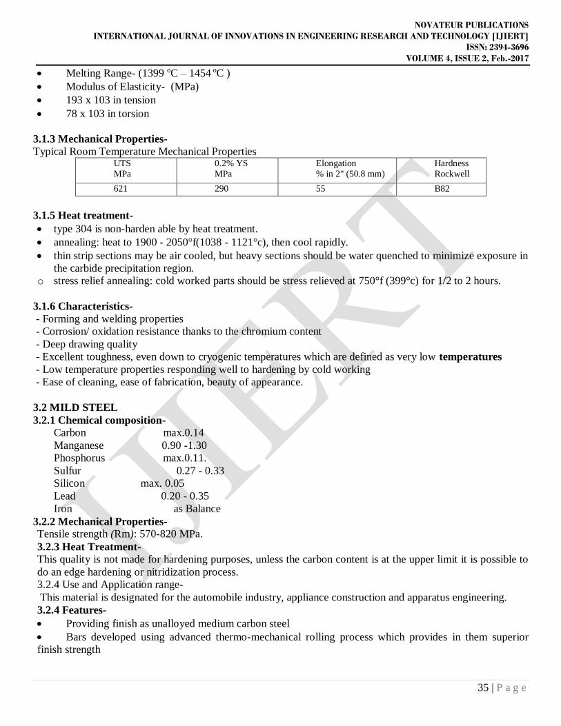
Fig 6.7 SEM Photograph Of Brittle Fracture At 400x
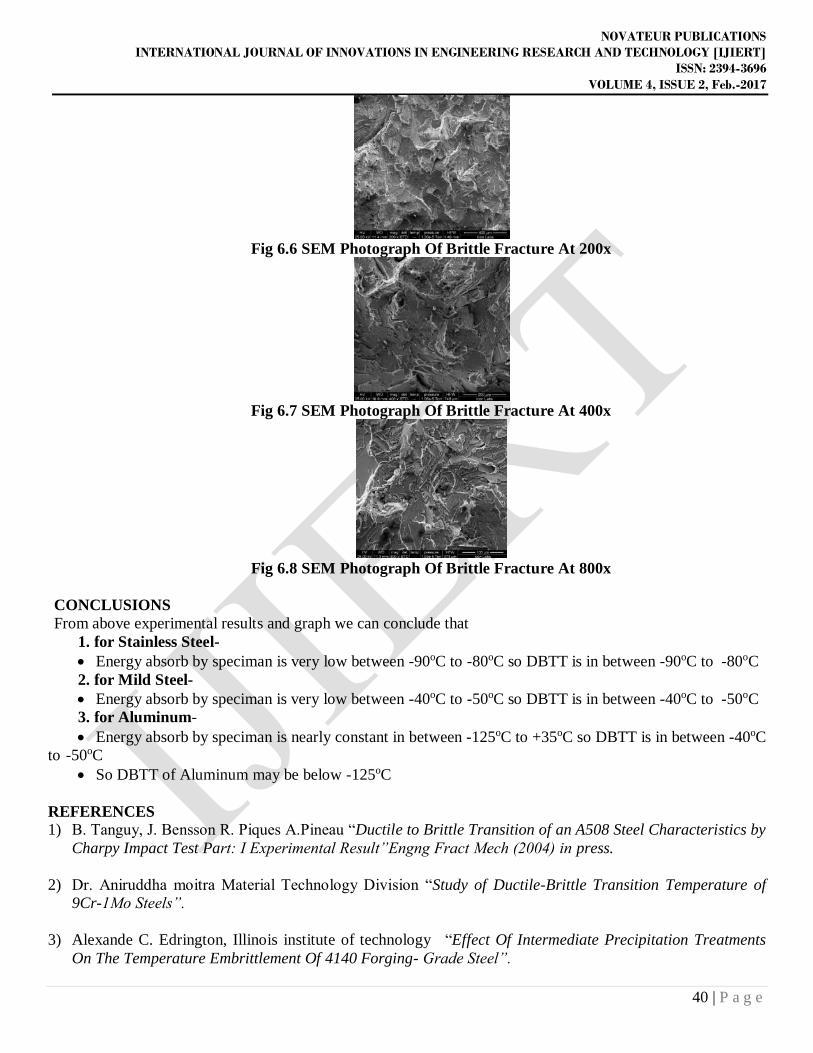
Fig 6.8 SEM Photograph Of Brittle Fracture At 800x
CONCLUSIONS From above experimental results and graph we can conclude that
1. for Stainless Steel- Energy absorb by speciman is very low between -90oC to -80oC so DBTT is in between -90oC to -80oC 2. for Mild Steel- Energy absorb by speciman is very low between -40oC to -50oC so DBTT is in between -40oC to -50oC 3. for Aluminum- Energy absorb by speciman is nearly constant in between -125oC to +35oC so DBTT is in between -40oC
to -50oC So DBTT of Aluminum may be below -125oC
REFERENCES 1) B. Tanguy, J. Bensson R. Piques A.Pineau “Ductile to Brittle Transition of an A508 Steel Characteristics by
Charpy Impact Test Part: I Experimental Result”Engng Fract Mech (2004) in press.
2) Dr. Aniruddha moitra Material Technology Division “Study of Ductile-Brittle Transition Temperature of 9Cr-1Mo Steels”.
3) Alexande C. Edrington, Illinois institute of technology “Effect Of Intermediate Precipitation Treatments On The Temperature Embrittlement Of 4140 Forging- Grade Steel”.
NOVATEUR PUBLICATIONS
INTERNATIONAL JOURNAL OF INNOVATIONS IN ENGINEERING RESEARCH AND TECHNOLOGY [IJIERT]
ISSN: 2394-3696
VOLUME 4, ISSUE 2, Feb.-2017
41 | P a g e
4) M.L. Hamilton and P.H.Jones “ Effect Of Heat Treatment And Test Method On DBTT Of V-5Cr-5Ti Alloy Steel”
5) Standard Test Methods(Designation: A 370 – 02e ) and Definitions for Mechanical Testing of Steel Products.
6) Dr. V.D. Kodgire And S.V. Kodgire “Material Science And Metallurgy”, Everest Publication.
7) www.aksteels.com (for stainless steel 304)
8) www.kleinmetals.ch (for mild steel)
9) (Source:- http://en.wikipedia.org/wiki/List_of_Indian_Naval_accidents)