
Detection of Spin-Polarized Electrons: Spin-polarized Photoemission and Spin Polarized Inverse...
21
Detection of Spin-Polarized Electrons: Spin-polarized Photoemission and Spin Polarized Inverse Photoemission I. Photoemission II.Mott Detectors: III.Spin Polarized Inverse Photoemission IV.Other Techniques 1
-
Upload
patience-leonard -
Category
Documents
-
view
245 -
download
4
Transcript of Detection of Spin-Polarized Electrons: Spin-polarized Photoemission and Spin Polarized Inverse...

Detection of Spin-Polarized Electrons:Spin-polarized Photoemission and Spin Polarized Inverse
Photoemission
I. Photoemission
II. Mott Detectors:
III. Spin Polarized Inverse Photoemission
IV. Other Techniques
1

Outer Hemisphere (VO)
Inner Hemisphere VI
e- E = KE
Retarding/focussing lens
Retards Electrons to Epass
KE-Vretard = Epass (Vretard varied, Epass constant)
e- E = Epass
Detector= Channeltron or Channelplate
Pass Energy = C(V0-VI)
Only electrons with E = Epass+/- δE get thru the analyzer
δE increases with Epass
Note: Intensity Increases with Pass energy, resolution decreases!
Conventional Detector/Spin Integrated Photoemission
hv
2

M
e-
AnalyzerExciting photon does NOT directly couple with electron spin
Therefore, Spin is conserved during photoemission process (e.g., J. Osterwalder: Spin-Polarized Photoemission, Lect. Notes Phys. 697, 95–120 (2006)
Need a detector that detects electron spin direction: The MOTT detector
3

Detection of Spin-Polarized Electrons:
See T. J. Gay and F. B. Dunning, Rev. Sci. Inst. 63 (1992) 1635See also N. F. Mott., Proc. Roy. Soc. A 135 (1932) 429
Consider Fig. 1 (Gay, Dunning). An unpolarized electron beam with equal numbers of spins P and AP to vector n̂�1
Heavy atom nuclei
4

To a reasonable approximation, high energy electrons will interact with the bare nucleus charge Z.
The motion of the electrons in the presence of the field E due to the nuclear charge sets up a magnetic field (B) on the electrons
v = electron velocity
The nuclear field is (Gay, Dunning) given as (Ze/r3)r. (r = elec.-nucleus distance.) Since rxv = L, the orbital angular momentum of the electron, we have
5
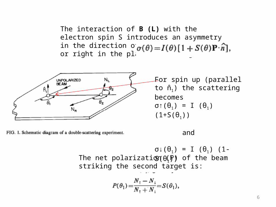
The interaction of B (L) with the electron spin S introduces an asymmetry in the direction of scattering to left or right in the plane of the figure:
For spin up (parallel to n̂�1) the scattering becomesσ↑(θ1) = I (θ1) (1+S(θ1))
and
σ↓(θ1) = I (θ1) (1-S(θ1))
The net polarization (P) of the beam striking the second target is:
6

Scattering through the second target (also a high z nucleus) will yield a similar asymmetry, given by:
Thus, if one knows (or independently measures) S for a given scattering angle, measuring the number of electrons scattered to the left and right will give you the polarization of the incoming beam
For coplanar scattering, NL α N↑(1+S(θ2)) + N↓(1-S(θ2)), etc. and:
7

Outer Hemisphere (VO)
Inner Hemisphere VI
e- E = KE
Retarding/focussing lens
Retards Electrons to Epass
e- E = Epass
Detectors= Channeltron or Channelplate
Conventional Detector/Spin Integrated Photoemission
hv
R
To detect spins of incoming polarized electrons, we need a single heavy target(gold does not oxidize) , and 2 (or 4 if fancy) channeltrons to measure beam polariztion.
L
8

Schematic of Mott Detector with retarding grids in front of the Channeltrons. (Incoming electrons are accelerated after energy selection in hemispherical analyzer to provide good scattering assymmetries, see Gay and Dunning)
The efficiency (Є) of the detector is given by:
Unfortunately, the efficiency of typical Mott Detectors is~10-3 – 10-4
Patience is a virtue during spin polarized photoemission!
9

Mott Detectors based on designs similar to this are sold commercially
See Gray, Dunning and ref. therein
10

Because of low count rates in Spin polarized measurements, it is possible to combine a conventional detector for spin integrated measurements with a Mott detetector and switch back and forth between them! H. Berntsen, et al., REVIEW OF
SCIENTIFIC INSTRUMENTS 81, 035104 2010
11

(E. Vescovo, et al)
12

Oxygen exposure:Polarization of surface near Fermi level disappears.(E. Vescovo, et al)
13
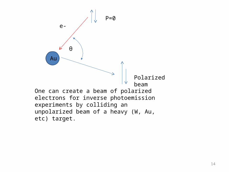
θ
Au
e-P=0
Polarized beam
One can create a beam of polarized electrons for inverse photoemission experiments by colliding an unpolarized beam of a heavy (W, Au, etc) target.
14

Rotator
Laser
GaAs B
G-MDetector
G-M Detectors
Spin Gun
MagnetGaAsCrystal
Cs Source
O2
Lin.Transport
Sample MottDetector
h
Dowben Group Facility for spin-polarized inverse photoemission
15
Dowben group uses photoelectrons from GaAs
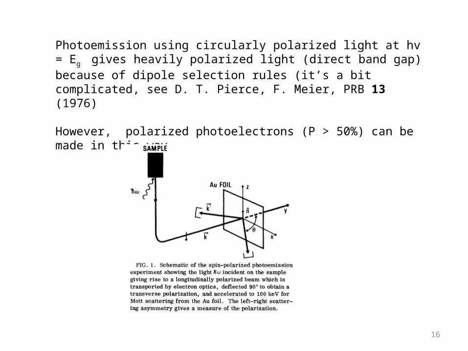
Photoemission using circularly polarized light at hv = Eg gives heavily polarized light (direct band gap) because of dipole selection rules (it’s a bit complicated, see D. T. Pierce, F. Meier, PRB 13 (1976)
However, polarized photoelectrons (P > 50%) can be made in this way.
16

Photoemission from GaAs is enhanced with a thin coating of Cs to yield a negative electron affinity (CBM below vacuum level)
17

Other techniques:
Magnetic circular dichroism (change in polariztion of reflected light)
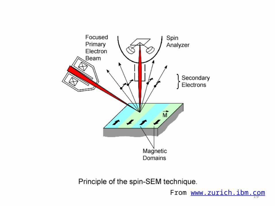
Spin polarized (SEM)—looking at magnetic domains
Spin polarized LEED—hard to measure net polarization, but can detect surface magnetic lattices
Spin polarized neutron detection magnetic unit cells of bulk lattices
18

Browning, et al.J. Elect. Spect. & Related Phen. 51(1990) 315
Spin polarized SEM useful for measuring magnetic domains.
20

Figure 1-3. Magnetic domain image of the Fe(001), where magnetization direction is shown by the gray level. The relationship between the magnetization direction and the gray level is given by the graded band above the domain image; central gray shows a right direction, lighter gray
shows a counterclockwise direction, and darker gray shows a clockwise direction.
from unit.aist.go.jp
Correlated electron research center
21