Detection and prevention of Man in the Middle attacks in...
99
AALBORG UNIVERSITY Detection and prevention of Man in the Middle attacks in Wi-Fi technology by Charalampos Kaplanis A thesis submitted in partial fulfillment for the degree of Master in Science in the Institue of Electronic Systems Department of Comunication Technology August 2015
Transcript of Detection and prevention of Man in the Middle attacks in...
AALBORG UNIVERSITY
Detection and prevention of Man in the
Middle attacks in Wi-Fi technology
by
Charalampos Kaplanis
A thesis submitted in partial fulfillment for the
degree of Master in Science
in the
Institue of Electronic Systems
Department of Comunication Technology
August 2015

Declaration of Authorship
I, Charalampos Kaplanis, declare that this thesis titled, ‘Detection and prevention of
Man in the Middle attacks in Wi-Fi technology’ and the work presented in it are my
own. I confirm that:
� This work was done wholly or mainly while in candidature for a research degree
at this University.
� Where any part of this thesis has previously been submitted for a degree or any
other qualification at this University or any other institution, this has been clearly
stated.
� Where I have consulted the published work of others, this is always clearly at-
tributed.
� Where I have quoted from the work of others, the source is always given.
� I have acknowledged all main sources of help.
Signed:
Date:
i

AALBORG UNIVERSITY
Abstract
Institue of Electronic Systems
Department of Comunication Technology
Master in Science
by Charalampos Kaplanis
Nowadays wireless networks tends to be more and more popular among the population
with the millions of users. In a wireless environment everybody is to access the wireless
transmitted data. This feature gives the capability to some vicious users to deceive
the clients of a wireless network by imitating the characteristics of a Wireless Access
Point(AP), thus staling valuable information from them. This kind of attack, where a
fake Access Point is set up to deceive the clients from the legitimate one, is known as
the Man-in-The-Middle attack(MITM). The main focus of this Thesis is to detect and
actively prevent the attacker of performing the MITM attack.
In the first part of the Thesis a fake AP will be created mimicking the characteristics of
a legitimate one. Then a series of Denial of Service(DoS) attacks will be conducted to
the legitimate AP in order to whisk the clients from their AP and force them to connect
to the fake AP. Finally, since the attack is successful the traffic of the clients will be
intercepted to reveal their private information.
The second part of the Thesis focuses on the detection and the prevention of a MITM
attack. A system will be developed that it will be able to store the legitimate APs
in a database and to perform scanning operations in the vicinity. Since the MITM
attack is based mostly on deception, the system will be able to recognise any fake APs
that are meant to be used in a MITM attack. Then system will automatically prevent
these APs to provide any service to the deceived clients. The above experiment have
been implemented using Backtrack 5R3 and Kali linux distributions and the system was
developed using the Python language.. . .

Acknowledgements
Firstly, I would like to special delivery my sincere gratitude to my advisors Jens Myrup
Pedersen and Rasmus Lovenstein Olsen for the support of my study and research, for
their patience, motivation, and understanding. The guidance that have been provided
to me helped me in all the time of research and writing of this thesis.
I would also like express my gratitude to the the study board because they gave me the
opportunity to finish my Thesis granting me extra time. After a very difficult period
for me, their decision allowed my to complete my Thesis. Without their understanding
I would not be able to complete it.
My sincere thanks also goes to the Stackoverflow and OffensiveSecurity forum members
that aided me. Their contribution has been more than valuable for me to complete my
Thesis.
Last but not the least, I would like to thank my family and fiancee for supporting and
encouraging me throughout writing this thesis.. . .
iii
Contents
Declaration of Authorship i
Abstract ii
Acknowledgements iii
List of Figures vi
List of Tables ix
1 Introduction 1
2 Background Theory 3
2.1 TCP/IP and OSI Models . . . . . . . . . . . . . . . . . . . . . . . . . . . 3
2.2 Wi-FI and Ethernet . . . . . . . . . . . . . . . . . . . . . . . . . . . . . . 5
2.2.1 Physical Layer . . . . . . . . . . . . . . . . . . . . . . . . . . . . . 5
2.2.2 MAC Sublayer . . . . . . . . . . . . . . . . . . . . . . . . . . . . . 6
2.2.2.1 Exposed Station Problem . . . . . . . . . . . . . . . . . . 7
2.2.2.2 Hidden Station Problem . . . . . . . . . . . . . . . . . . . 8
2.2.3 Wi-Fi Network Topologies . . . . . . . . . . . . . . . . . . . . . . . 10
2.2.4 Basic Service Set . . . . . . . . . . . . . . . . . . . . . . . . . . . . 10
2.2.5 Extended Service Set . . . . . . . . . . . . . . . . . . . . . . . . . . 11
2.3 Security Mechanisms . . . . . . . . . . . . . . . . . . . . . . . . . . . . . . 12
2.3.1 Hidden ESSID . . . . . . . . . . . . . . . . . . . . . . . . . . . . . 12
2.3.2 MAC Address Filtering . . . . . . . . . . . . . . . . . . . . . . . . 12
2.3.3 Password Authentication Mechanisms . . . . . . . . . . . . . . . . 13
2.3.3.1 WEP . . . . . . . . . . . . . . . . . . . . . . . . . . . . . 13
2.3.3.2 WPA/WPA2 . . . . . . . . . . . . . . . . . . . . . . . . . 15
3 The Man-In-The-Middle Attack 18
3.1 Introduction . . . . . . . . . . . . . . . . . . . . . . . . . . . . . . . . . . . 18
3.2 Implementing a Man In The Middle attack . . . . . . . . . . . . . . . . . 19
3.2.1 Information gathering . . . . . . . . . . . . . . . . . . . . . . . . . 20
3.2.2 Fake Access Point . . . . . . . . . . . . . . . . . . . . . . . . . . . 21
3.2.3 Connecting the Fake Access Point . . . . . . . . . . . . . . . . . . 23
iv

Contents v
3.2.3.1 Bridged Fake Access Point . . . . . . . . . . . . . . . . . 23
3.2.3.2 Routed Fake Access Point . . . . . . . . . . . . . . . . . . 24
3.2.4 Improvements on MITM attacks . . . . . . . . . . . . . . . . . . . 27
3.3 Manipulating the Clients . . . . . . . . . . . . . . . . . . . . . . . . . . . . 28
3.3.1 Jamming Attacks . . . . . . . . . . . . . . . . . . . . . . . . . . . . 28
3.3.2 Vulnerabilities in 802.11x MAC . . . . . . . . . . . . . . . . . . . . 30
3.3.3 Connection and disconnection process . . . . . . . . . . . . . . . . 33
3.3.4 Implementation of Jamming attacks . . . . . . . . . . . . . . . . . 35
3.3.4.1 Association/Authentication food attack . . . . . . . . . . 35
3.3.4.2 De-authentication attack . . . . . . . . . . . . . . . . . . 37
3.3.4.3 Multi-AP De-authentication attack . . . . . . . . . . . . 39
3.4 Traffic interception . . . . . . . . . . . . . . . . . . . . . . . . . . . . . . . 42
4 Design of Detection and Prevention System 46
4.1 Introduction . . . . . . . . . . . . . . . . . . . . . . . . . . . . . . . . . . . 46
4.2 Design overview . . . . . . . . . . . . . . . . . . . . . . . . . . . . . . . . . 48
4.2.1 Data Collection . . . . . . . . . . . . . . . . . . . . . . . . . . . . . 49
4.2.2 Database Update . . . . . . . . . . . . . . . . . . . . . . . . . . . . 50
4.2.3 Fake AP Detector . . . . . . . . . . . . . . . . . . . . . . . . . . . 52
5 Implementation of Detection and Prevention System 54
5.1 Introduction . . . . . . . . . . . . . . . . . . . . . . . . . . . . . . . . . . . 54
5.2 Data Collection . . . . . . . . . . . . . . . . . . . . . . . . . . . . . . . . . 54
5.3 Database Update . . . . . . . . . . . . . . . . . . . . . . . . . . . . . . . . 63
5.3.1 Fake AP Detector . . . . . . . . . . . . . . . . . . . . . . . . . . . 66
6 Test and Results 72
6.1 Introduction . . . . . . . . . . . . . . . . . . . . . . . . . . . . . . . . . . . 72
6.2 Test Setup . . . . . . . . . . . . . . . . . . . . . . . . . . . . . . . . . . . . 72
6.3 Test Description . . . . . . . . . . . . . . . . . . . . . . . . . . . . . . . . 73
6.4 Results . . . . . . . . . . . . . . . . . . . . . . . . . . . . . . . . . . . . . . 77
7 Conclusion 83
Bibliography 85

List of Figures
1.1 Worldwide wireless users(in millions) . . . . . . . . . . . . . . . . . . . . . 1
2.1 TCP/IP data flow between two systems . . . . . . . . . . . . . . . . . . . 4
2.2 TCP/IP and OSI models . . . . . . . . . . . . . . . . . . . . . . . . . . . 4
2.3 CSMA/CD mechanism . . . . . . . . . . . . . . . . . . . . . . . . . . . . . 7
2.4 Exposed station problem . . . . . . . . . . . . . . . . . . . . . . . . . . . . 8
2.5 Hidden Station problem . . . . . . . . . . . . . . . . . . . . . . . . . . . . 8
2.6 CSMA/CA mechanism . . . . . . . . . . . . . . . . . . . . . . . . . . . . . 9
2.7 Star and Mesh topologies . . . . . . . . . . . . . . . . . . . . . . . . . . . 10
2.8 Extended Service Set . . . . . . . . . . . . . . . . . . . . . . . . . . . . . . 11
2.9 Four step Shared key authentication process . . . . . . . . . . . . . . . . . 14
2.10 WEP encryption . . . . . . . . . . . . . . . . . . . . . . . . . . . . . . . . 15
2.11 WEP encryption . . . . . . . . . . . . . . . . . . . . . . . . . . . . . . . . 16
2.12 WPA2 encryption . . . . . . . . . . . . . . . . . . . . . . . . . . . . . . . . 17
3.1 Man In The Middle attack model . . . . . . . . . . . . . . . . . . . . . . . 19
3.2 Man In The Middle attack procedure . . . . . . . . . . . . . . . . . . . . . 20
3.3 Information gathering results . . . . . . . . . . . . . . . . . . . . . . . . . 21
3.4 Code and result of fake AP . . . . . . . . . . . . . . . . . . . . . . . . . . 22
3.5 New information gathering results . . . . . . . . . . . . . . . . . . . . . . 22
3.6 Probe Requests . . . . . . . . . . . . . . . . . . . . . . . . . . . . . . . . . 23
3.7 Bridged Access Point . . . . . . . . . . . . . . . . . . . . . . . . . . . . . . 23
3.8 Code for bridged AP . . . . . . . . . . . . . . . . . . . . . . . . . . . . . . 24
3.9 Routed Access Point . . . . . . . . . . . . . . . . . . . . . . . . . . . . . . 25
3.10 DHCP configuration . . . . . . . . . . . . . . . . . . . . . . . . . . . . . . 26
3.11 Code for routed AP . . . . . . . . . . . . . . . . . . . . . . . . . . . . . . 26
3.12 IP tables configuration . . . . . . . . . . . . . . . . . . . . . . . . . . . . . 27
3.13 structure of a 802.11 frame 1/2 . . . . . . . . . . . . . . . . . . . . . . . . 31
3.14 structure of a 802.11 frame 2/2 . . . . . . . . . . . . . . . . . . . . . . . . 32
3.15 Connection process . . . . . . . . . . . . . . . . . . . . . . . . . . . . . . . 34
3.16 Disconnection process . . . . . . . . . . . . . . . . . . . . . . . . . . . . . 35
3.17 Authentication flood process . . . . . . . . . . . . . . . . . . . . . . . . . 36
3.18 code to conduct authentication flood attack . . . . . . . . . . . . . . . . . 37
3.19 Authentication flood attack in progress . . . . . . . . . . . . . . . . . . . . 37
3.20 Deuthentication process . . . . . . . . . . . . . . . . . . . . . . . . . . . . 38
3.21 Codes for the de-authentication attack . . . . . . . . . . . . . . . . . . . . 39
3.22 Broadcast De-authentication attack in progress . . . . . . . . . . . . . . . 39
3.23 Information gathering with multiple results . . . . . . . . . . . . . . . . . 40
vi
List of Figures vii
3.24 Rules list for blacklisted APs . . . . . . . . . . . . . . . . . . . . . . . . . 41
3.25 Code for Multi-AP De-authentication attack . . . . . . . . . . . . . . . . . 41
3.26 Multi-AP de-authentication attack in progress . . . . . . . . . . . . . . . . 41
3.27 De-authenticated clients . . . . . . . . . . . . . . . . . . . . . . . . . . . . 42
3.28 De-authenticated client an the Fake AP . . . . . . . . . . . . . . . . . . . 42
3.29 Ettercap and Sslstrip implemetation . . . . . . . . . . . . . . . . . . . . . 43
3.30 Code for Sslstrip . . . . . . . . . . . . . . . . . . . . . . . . . . . . . . . . 43
3.31 Code for Ettercap . . . . . . . . . . . . . . . . . . . . . . . . . . . . . . . 44
3.32 Sslstrip in progress . . . . . . . . . . . . . . . . . . . . . . . . . . . . . . . 44
3.33 Captured credentials with Ettercap . . . . . . . . . . . . . . . . . . . . . . 45
4.1 Overall flowchart of the mechanism . . . . . . . . . . . . . . . . . . . . . . 48
4.2 Flowchart of the Data Collection module . . . . . . . . . . . . . . . . . . . 49
4.3 Flowchart of the Database module . . . . . . . . . . . . . . . . . . . . . . 51
4.4 Flowchart of the Fake AP Detector . . . . . . . . . . . . . . . . . . . . . . 52
6.1 Overview of the test set up with all the participants . . . . . . . . . . . . 73
6.2 Overview of the scenario 1 set up . . . . . . . . . . . . . . . . . . . . . . . 74
6.3 Overview of the scenario 2 set up . . . . . . . . . . . . . . . . . . . . . . . 75
6.4 Overview of the scenario 3 set up . . . . . . . . . . . . . . . . . . . . . . . 76
6.5 APs discovered and added to the protection list . . . . . . . . . . . . . . . 77
6.6 Fake AP discovery based on the BSSID . . . . . . . . . . . . . . . . . . . 78
6.7 Alert display and preparation for De-authentication . . . . . . . . . . . . 78
6.8 De-authentication to the fake AP . . . . . . . . . . . . . . . . . . . . . . . 79
6.9 Discovery of fake AP based on the broadcast channel . . . . . . . . . . . . 80
6.10 Alert display and preparation for De-authentication . . . . . . . . . . . . 80
6.11 De-authentication to the fake AP . . . . . . . . . . . . . . . . . . . . . . . 81
6.12 Scan results . . . . . . . . . . . . . . . . . . . . . . . . . . . . . . . . . . . 82

Listings
5.1 Database creation . . . . . . . . . . . . . . . . . . . . . . . . . . . . . . . 55
5.2 Initialization of de-authentication options . . . . . . . . . . . . . . . . . . 56
5.3 Initialization of de-authentication options . . . . . . . . . . . . . . . . . . 57
5.4 Creation of Monitor interface . . . . . . . . . . . . . . . . . . . . . . . . . 58
5.5 Scan and Data collection and Filtering . . . . . . . . . . . . . . . . . . . . 59
5.6 BSSID and SSID Discovery submodule . . . . . . . . . . . . . . . . . . . . 60
5.7 Airodump-ng csv output parsing . . . . . . . . . . . . . . . . . . . . . . . 61
5.8 Display Scanned Results sub-module . . . . . . . . . . . . . . . . . . . . . 62
5.9 SSID selection sub-module . . . . . . . . . . . . . . . . . . . . . . . . . . . 63
5.10 BSSID selection sub-module . . . . . . . . . . . . . . . . . . . . . . . . . . 64
5.11 BSSID deletion sub-module . . . . . . . . . . . . . . . . . . . . . . . . . . 65
5.12 De-authentication Parameters sub-module . . . . . . . . . . . . . . . . . . 65
5.13 Fake AP Detector and Exit options . . . . . . . . . . . . . . . . . . . . . . 66
5.14 Comparison Scanned with Stored data . . . . . . . . . . . . . . . . . . . . 67
5.15 Fake AP with different BSSID de-authentication . . . . . . . . . . . . . . 68
5.16 Fake AP with same SSID and BSSID de-authentication . . . . . . . . . . 69
5.17 De-authentication Mechanism . . . . . . . . . . . . . . . . . . . . . . . . . 70
viii

List of Tables
1.1 IEEE 802.11x protocols . . . . . . . . . . . . . . . . . . . . . . . . . . . . 2
3.1 Effectiveness of jamming models[9] . . . . . . . . . . . . . . . . . . . . . . 30
ix

Dedicated to my fiancee. . .
x

Chapter 1
Introduction
Wireless networking nowadays is the most popular way of networking for users because
it offers flexibility and ease of use. Millions of people use wireless networks to work,
study or just surf the Internet all over the globe. The number of users tends to increase
every year world wide. The following figure illustrates the growth of worldwide wireless
application user base from 2009 to 2016. As stated in the graph the expected mobile
wireless application users in 2016 will reach 565.4 million.
Figure 1.1: Worldwide wireless users(in millions)
There are many different wireless technologies and products on the market that they
use different protocols. The most popular products in comparison with the others are
those based on the IEEE 802.11x, known as Wi-Fi devices. Besides Wi-Fi there are
other products such as Wi-Max which are based on IEEE 802.16 and WPAN (Wireless
Personal Area Networks) which are based on IEEE 802.15. Bluetooth is the most known
member of the last family. Wi-Fi is by far the most popular and used wireless local area
network. The reason for this popularity of the Wi-fi devices is the low purchase cost,
the increased reliability and the high speeds they can provide to the user.
1

List of Tables 2
The Wi-Fi alliance is an organization responsible for the certification of Wi-Fi products
and technologies. The word Wi-Fi suggests that a product is based on the IEEE 802.11
technology, certified by the organization. The Wi-Fi alliance has played a major role on
the development and the improvement of the Wi-Fi technology over the years. The first
version of the Wi-Fi was created in 1997 and it was based on the IEEE 802.11 with the
ability to transfer data with 2MB/s. Since then five major standards have been created
named IEEE 802.11a, IEEE802.11b, IEEE 802.11g, IEEE 802.11n and IEEE 802.11ac.
There are other 802.11x standards besides the aforementioned like the 802.11i and the
802.11e. These standards have been used for experimental reasons and test-beds for new
implementation on the 802.11x standard. The 802.11i standard introduced the WPA/2
protection to the wireless network and the 802.11e standard was developed to enhance
and improve the Quality of Service (QoS).
The use of the 802.11x, or Wi-Fi, made wireless networking very convenient and reliable
and thus it has been adopted by millions of users. But this wireless evolution comes
with a cost. Given the fact that Wi-fi uses a shared medium to transfer the data it
is easier for malicious users to intercept them using the protocols vulnerabilities. The
main priority for all the network administrators is the safety of the transmitted data on
their network.
Standard Frequency Max data rate Modulation
802.11 2.4GHz 2Mbps FHSS/DSSS
802.11a 5GHz 54Mbps OFDM
802.11b 2.4GHz 11Mbps DSSS
802.11g 2.4GHz 54Mbps OFDM/DSSS
802.11n 2.4GHz/5GHz 150Mbps OFDM
802.11ac 5GHz 866Mbps OFDM
Table 1.1: IEEE 802.11x protocols
Chapter 2
Background Theory
2.1 TCP/IP and OSI Models
In every network there is a set of functions necessary for its operation. These function
are different between them and they form layers. Every layer is served by the previous
one and serves the next one.
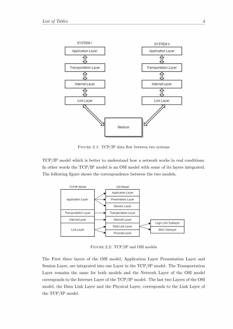
Such a model is the TCP/IP model and it consist of four layers. The layers consists
of the Application Layer, the Transportation Layer, the Internet Layer and the Link
Layer. In the figure 2.1 there is a network which is based on the TCP/IP model. When
System I wants to make a transmission to System II the Application Layer of System
I will generate the data and then they will be send to the Transportation Layer. The
Transportation Layer in System I is responsible to open a port on the system and after
doing so the data will be delivered to the Internet Layer. Internet Layer using IP
addresses will locate System II and the data will be passed to the Link layer. The Link
Layer has been shouldered with the task to transform all the data to a binary stream and
then send them through the used medium to the System’s II Link Layer, using wired,
wireless or optical methods. System’s II Link Layer will reconstruct the binary stream
correcting any possible errors that may have been caused during the transmission and
then the message will be delivered to the upper layers to be restored. Finally the data
will be delivered to the Application Layer. The whole process can be conducted from
the System II to the System I.
The second popular network model is the OSI (Open Systems Interconnection) and it
was created by the ISO organization. In comparison with the TCP/IP model, which
has 4 layers, the OSI model has seven layers. The additional layers is a method to
describe the functions of a network with grater accuracy in theory, in contrast with the
3
List of Tables 4
Figure 2.1: TCP/IP data flow between two systems
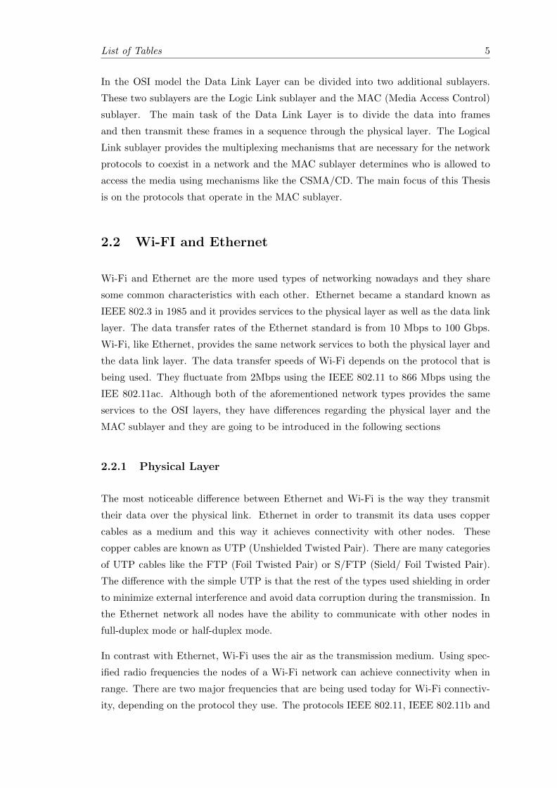
TCP/IP model which is better to understand how a network works in real conditions.
In other words the TCP/IP model is an OSI model with some of its layers integrated.
The following figure shows the correspondence between the two models.
Figure 2.2: TCP/IP and OSI models
The First three layers of the OSI model, Application Layer Presentation Layer and
Session Layer, are integrated into one Layer in the TCP/IP model. The Transportation
Layer remains the same for both models and the Network Layer of the OSI model
corresponds to the Internet Layer of the TCP/IP model. The last two Layers of the OSI
model, the Data Link Layer and the Physical Layer, corresponds to the Link Layer of
the TCP/IP model.
List of Tables 5
In the OSI model the Data Link Layer can be divided into two additional sublayers.
These two sublayers are the Logic Link sublayer and the MAC (Media Access Control)
sublayer. The main task of the Data Link Layer is to divide the data into frames
and then transmit these frames in a sequence through the physical layer. The Logical
Link sublayer provides the multiplexing mechanisms that are necessary for the network
protocols to coexist in a network and the MAC sublayer determines who is allowed to
access the media using mechanisms like the CSMA/CD. The main focus of this Thesis
is on the protocols that operate in the MAC sublayer.
2.2 Wi-FI and Ethernet
Wi-Fi and Ethernet are the more used types of networking nowadays and they share
some common characteristics with each other. Ethernet became a standard known as
IEEE 802.3 in 1985 and it provides services to the physical layer as well as the data link
layer. The data transfer rates of the Ethernet standard is from 10 Mbps to 100 Gbps.
Wi-Fi, like Ethernet, provides the same network services to both the physical layer and
the data link layer. The data transfer speeds of Wi-Fi depends on the protocol that is
being used. They fluctuate from 2Mbps using the IEEE 802.11 to 866 Mbps using the
IEE 802.11ac. Although both of the aforementioned network types provides the same
services to the OSI layers, they have differences regarding the physical layer and the
MAC sublayer and they are going to be introduced in the following sections
2.2.1 Physical Layer
The most noticeable difference between Ethernet and Wi-Fi is the way they transmit
their data over the physical link. Ethernet in order to transmit its data uses copper
cables as a medium and this way it achieves connectivity with other nodes. These
copper cables are known as UTP (Unshielded Twisted Pair). There are many categories
of UTP cables like the FTP (Foil Twisted Pair) or S/FTP (Sield/ Foil Twisted Pair).
The difference with the simple UTP is that the rest of the types used shielding in order
to minimize external interference and avoid data corruption during the transmission. In
the Ethernet network all nodes have the ability to communicate with other nodes in
full-duplex mode or half-duplex mode.
In contrast with Ethernet, Wi-Fi uses the air as the transmission medium. Using spec-
ified radio frequencies the nodes of a Wi-Fi network can achieve connectivity when in
range. There are two major frequencies that are being used today for Wi-Fi connectiv-
ity, depending on the protocol they use. The protocols IEEE 802.11, IEEE 802.11b and
List of Tables 6
IEEE 802.11g use the 2.4GHz band and the protocols IEEE 802.11a and IEEE 802.11
use the 5GHz band. IEEE 802.11n uses both bands depending on the manufacturer and
the desired speed. The transmission bands are divided into channels and the multitude
of the channels depends on the geographical region each device was made for. Unlike
Ethernet, Wi-fi cannot achieve full-duplex communication using the same channel. In
order to achieve that, the transmission frequency must be different in the reception.
2.2.2 MAC Sublayer
The MAC (Medium Access Control) is a mechanism that determines which frame is to
be send in a channel that is being accessed by multiple nodes. This control mechanism is
a necessity when the medium is shared like the Ethernet and the Wi-Fi. A fundamental
protocol in the MAC sublayer is the CSMA(Carrier Sense Multiple Access). The CSMA
mechanism senses the status of the channel. Before a transmission the mechanism checks
if the channel is available for use. In case the channel is idle the data are being sent to
the destination otherwise the node remains silent and periodically checks the channel to
identify its status. The moment the channels is available again the node will transmit.
The CSMA mechanism exists in both Wi-Fi and Ethernet with some differentiations
because of the physical layers.
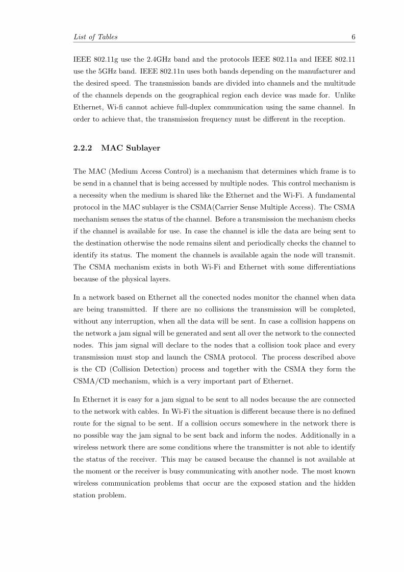
In a network based on Ethernet all the conected nodes monitor the channel when data
are being transmitted. If there are no collisions the transmission will be completed,
without any interruption, when all the data will be sent. In case a collision happens on
the network a jam signal will be generated and sent all over the network to the connected
nodes. This jam signal will declare to the nodes that a collision took place and every
transmission must stop and launch the CSMA protocol. The process described above
is the CD (Collision Detection) process and together with the CSMA they form the
CSMA/CD mechanism, which is a very important part of Ethernet.
In Ethernet it is easy for a jam signal to be sent to all nodes because the are connected
to the network with cables. In Wi-Fi the situation is different because there is no defined
route for the signal to be sent. If a collision occurs somewhere in the network there is
no possible way the jam signal to be sent back and inform the nodes. Additionally in a
wireless network there are some conditions where the transmitter is not able to identify
the status of the receiver. This may be caused because the channel is not available at
the moment or the receiver is busy communicating with another node. The most known
wireless communication problems that occur are the exposed station and the hidden
station problem.
List of Tables 7
Figure 2.3: CSMA/CD mechanism
Another reason is that in a wireless environment, it would b e difficult for the transmitter
to decide if the receiver is actually idle even though the channel between them may be
available. Thus multiple transmissions at the same time may corrupt each other. In a
wireless network, what really matters is not the status of the transmitter but the status
of the receiver. Two of the common wireless transmission problems are hidden station
problem and exposed station problem.
2.2.2.1 Exposed Station Problem
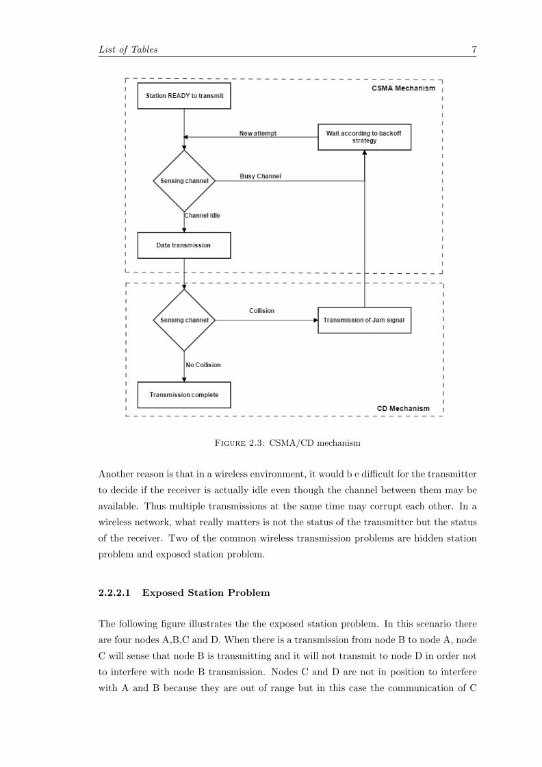
The following figure illustrates the the exposed station problem. In this scenario there
are four nodes A,B,C and D. When there is a transmission from node B to node A, node
C will sense that node B is transmitting and it will not transmit to node D in order not
to interfere with node B transmission. Nodes C and D are not in position to interfere
with A and B because they are out of range but in this case the communication of C

List of Tables 8
and D can begin only when the communication between A and B is finished. In this
case the exposed node is node C
Figure 2.4: Exposed station problem
2.2.2.2 Hidden Station Problem
The next picture illustrates the the hidden station problem. In this scenario there are
three nodes A,B and C. Both A and C nodes are in range of B node. In the same time
it can be seen that nodes A and C are not in range with each other. In case that B is
communicating with one of the nodes and the other one tries to establish a connection,
the on going communication will be disrupted seriously because none of the nodes A or
C are in position to determine if the channel is idle and ready for transmission.
Figure 2.5: Hidden Station problem

List of Tables 9
Taking the above problems into account the CA(Collision Avoidance) mechanism was
created. The CA mechanism works along with the CSMA mechanism in a wireless en-
vironment. When a node want to transmit to another node some data, first it transmits
an RTS(Request To Send) frame to the destination informing it. If the receiver node is
able to receive the data it replies with an CTS(Clear To Send) frame indicating that it
is ready to receive the data. When the CTS is received the transmission begins. During
the transmission some ACK(Acknowledgements) are being sent to the transmitter in
order to verify that the transmission is successful.
Figure 2.6: CSMA/CA mechanism

List of Tables 10
2.2.3 Wi-Fi Network Topologies
The definition of a network topology is the relationship, both in physical and in logical
terms, the nodes of a network have with each other. Wired networks are able to form
more topologies than the wireless ones. The total number of wired network topologies
are five: star topology, ring topology, tree topology bus topology and mesh topology. In
wireless network from the other hand only two types of topologies are available. The
star topology and the mesh topology.
Mesh topologies in wireless networks are also known as ad-hoc networks. In ad-hoc
networks the nodes of the network have direct communication with each other without
the need to connect to a base station or any other wired or wireless device. As long as
the nodes of such a network are in range with each other they can connect and exchange
data.
In contrast with the ad-hoc network, in a star topology wireless network all the nodes
of the network must connect to a base station. This station, also know as AP(Access
Point), is usually a part of a larger network connected with wires. The communication
in this topology is routed through the AP and through the AP the nodes of a wireless
network are able to communicate with other wired or wireless devices in the same or in
other networks, as long as the AP can access them. This kind of network is suitable for
offices, schools and hot spots and there fore its is used frequently.
Figure 2.7: Star and Mesh topologies
2.2.4 Basic Service Set
The BBS(Basic Service Set) is a set of devices that are associated to a WLAN(Wireless
Local Area Connection). This principal applies to both the ad-hoc networks and the star,
or infrastructure, networks. For infrastructure networks the BBS is referred as BBS and

List of Tables 11
for the ad-hoc networks the BBS is called IBBS(Independent BBS). It is independent
because the particular service set is not able to connect to another BBS.
Every BBS has a BSSID(basic service set identification) wich is used for identification.
In infrastructure networks the BSSID is based on the AP’s MAC address and it is
generated by the 24 bits OUI(Organization Unique Identifier). Every network interface
card (NIC) has its own 24 bits OUI. Usually many manufacturers use the same initial
digits in their NICs and thus they are easy to indentify.
2.2.5 Extended Service Set
An ESS(Extended Service Set) is a formation of many different interconnected BSSes in
one area. The APs are usually connected with cables to the same wired network. In an
ESS environment every AP has its own BSS identification also known as BSSID. But for
for reduced network complexity all the connected APs have a common ESS identification
known as ESSID. In order to achieve that all the APs must be in the same subnet and
to be connected to the same router. The maximum size of an ESSID is 32 bytes and
it can be alphanumeric. In such a network all the devices must be set to use the same
ESSID otherwise they will not able to comunicate.
Figure 2.8: Extended Service Set
An ESSID can contain many different BSSIDs in a large scale network and they can be
modified in a network at any moment. An ESSID is the name of the network and it is

List of Tables 12
broadcaster in a way that humans can identify it and connect to it using their network
devices.
2.3 Security Mechanisms
Every wireless network has some security mechanisms that prevent malicious users from
accessing the data that are being transmitted. The effectiveness and the complexity of
these mechanism varies but all of them can be bypassed from an experienced hacker.
The most commonly used mechanisms are MAC address filtering , hidden ESSID and
password authentication mechanisms such as WEP and WPA/WPA2.
2.3.1 Hidden ESSID
Every AP in order to announce its wireless network it broadcasts beacon frames with the
ESSID. This way the users that are in range are aware of the network and can connect
easily. But along with the normal users the network is visible to the malicious ones.
In order to hide the wireless network and make it invisible, the APs can deactivate the
broadcast of their ESSID when they transmit their beacons. In this case only the clients
that know the existence of the network can connect to it.
This method though is an additional security enchantment than a viable solution. If an
authorized client tries to connect to a network with a hidden ESSID a Probe Request
frame will be transmitted to the AP and the AP will respond with a Probe Response
frame. These two frames are unencrypted and they contain the hidden ESSID of the
netwrok, thus they can be easily intercepted by a malicious user.
2.3.2 MAC Address Filtering
The idea behind the MAC address filtering mechanism is simple. Since every NIC has
a unique MAC address and an AP can create a list with legitimate MAC address that
will be allowed to have access to the wireless network. Every time a user, whose device’s
MAC address is on the list, attempts to connect to the network the AP will recognize
the MAC address and it will provide access. Other devices whose MAC addresses are
not on the list will not be allowed to connect, preventing this way any undesirable users.
Like the hidden ESSID method, MAC address filtering is also a security enchantment
than a complete solution. Despite the uniqueness of a MAC address of a NIC, there
are tools that are able to alter the MAC address of a NIC in many operation systems.
List of Tables 13
Especially in linux based operating system the process is very easy and fast. From
the moment a malicious user identifies a legitimate user who is connected to an AP he
can copy the legitimates user’s MAC address and change his own, making him able to
connect to the access point since his MAC address will be in the AP’s whitelist.
2.3.3 Password Authentication Mechanisms
The password security mechanisms are based on a password that the user and the AP
know and through encryption it assures safe and encrypted wireless communication.
The mechanisms can be separated into two steps. The Authentication step and the
Encryption step. The responsibility of a authentication mechanism is the creation of
credential in order to distinguish the legitimacy of a user. Then, after the authentication
has occurred the user will come across the encryption mechanism. The encryption
mechanism uses algorithms where the transmitted data are encrypted and even if a
malicious user has bypassed the authentication mechanism these data are useless because
they must be deciphered.
Currently there are types of security mechanisms that are being used most frequently
in Wi-Fi networks: WEP, WPA/WPA2 and WPA/WPA2-Entreprise.
2.3.3.1 WEP
The first security mechanism that has been applied to Wi-Fi networks is WEP(Wired
Equivalent Privacy) and it was adopted by the early version of Wi-Fi protocols and it
is supported by the rest. As the acronym of the mechnsm states, it was created for
equivalent privacy with the wired networks. But WEP had many flaws from the very
beginning that made this protection extremely weak in a short time.
Authentication Mechanism Weakness: WEP uses two kinds of authentication
mechanisms. The first authentication mechanism is an Open System authentication.
In this case there is no need for the user to provide any credentials to the AP in order to
authenticate. All the users can authenticate and then associate to the AP. But in order
to decrypt the the data frames the user must have the right keys.
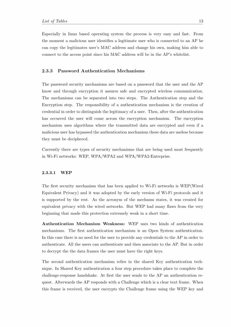
The second authentication mechanism relies in the shared Key authentication tech-
nique. In Shared Key authentication a four step procedure takes place to complete the
challenge-response handshake. At first the user sends to the AP an authentication re-
quest. Afterwards the AP responds with a Challenge which is a clear text frame. When
this frame is received, the user encrypts the Challenge frame using the WEP key and
List of Tables 14
then transmits the encrypted Challenge to the AP along with a new authentication re-
quest. The AP decrypts the received frames and if they match the Challenge text the
it send back to the user a positive response.
The second authentication method is widely used in favor of the first because it adds one
more layer of security. Nevertheless the whole process is vulnerable. An attacker can
monitor the the handshake between the client and the AP and both the unencrypted
Challenge text and encrypted response can be intercepted and captured. When this is
done, using a single XOR operation the attacker can retrieve a key stream which can be
used to encrypt future text challenges broadcasted by the AP without the need of the
pass phrase. Thus the attacker can bypass the authentication mechanism.
Figure 2.9: Four step Shared key authentication process

List of Tables 15
Figure 2.10: WEP encryption
Encryption Mechanism Weakness: WEP protection uses RC4 algorithm to encrypt
the data frames. The key, which is entered by the user, in concatenated with an 24-
bit IV(Initialization Vector) which is transmitted as plain text. The purpose of the
IV is to prevent repetitions but because it is 24-bit this cant be ensured in heavy load
environment. The outcome of the concatenated code then is passed to the RC4 for
encryption. Like the Authentication Mechanism flaw, a XOR operation can be applied
here as well between the key stream and the plain text in order to get the encrypted
text. WEP keys can have 64bit and 128bit lengths but the IVs remain at 24bits and
this is why the system is vulnerable. By gathering a large amounts of packets and using
brute force methods the WEP key can be obtained in a matter of minutes using an up
to date personal computer.
2.3.3.2 WPA/WPA2
The fast compromisation of WEP encryption was not expected and it created a security
gap in Wi-Fi networks. In order to face the problem Wi-Fi Alliance created a new
security mechanism in order to fill the gap. By that time million of devices have been
sold so the new solution had to be compatible with older devices through a firmware
update, instead of forcing the users to buy new devices. Thus the WPA(Wi-Fi Protected
Access) was created. In comparison with WEP, WPA has IV with 48 bits length because
of the use of TKIP(Temporal Key Integrity Protocol) protocol. Additionally the use of
CRC had been replaced with the MIC(Message Integrity Check) algorithm in order to
preserve data integrity during transmission.
Although the WPA was secure enough for Wi-Fi networks it was replaced from a sec-
ond more secure version, the WPA2. In WPA2, which was introduced with the IEEE

List of Tables 16
802.11i, the MIC algorithm was replaced with the CCMP(Counter Mode Cipher Block
Chaining Message Authentication Code Protocol) and the RC4 encryption mechanism
was replaced by the AES(Advanced Encryption Standard). This gave the WPA2 the
ability to have 128 bit keys.
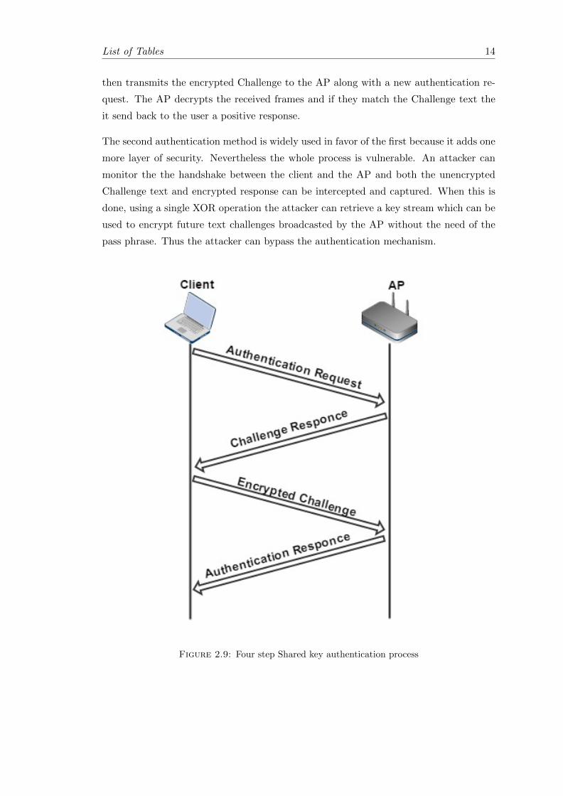
Despite the fact that WPA/WPA2 increased significantly the security in Wi-Fi net-
works it also has flaws. A major flaw on the WPA/WPA2 mechanism can be found
on the four-way handshake between the client and the AP. The SSID along with the
WPA/WPA2 they form a key-stream that is encrypted by an SHA-1 algorithm producing
a 160 bit hash value which is the PMK(Pairwise Master Key). Then by concatenating
the PMK with the information gathered from the four way handshake the outcome is
the PTK(Pairwise Transient Key). PTK is a temporary key and it is used in order not
to broadcast the PMK and the necessary information from the four way handshake are
the clients and the AP MAC addresses along with ANonce ans SNonce who are uniform
random numbers. Then the PTK along with plain text is ciphered with the TKIP/AES
algorithm.
Figure 2.11: WEP encryption
When the four way handshake occurs a malicious user can intercept it. Information
such as ANonce, SNonce, Client MAC address, AP MAC Address and the MIC value
can easily be found. Using bruteforce techniques and dictionary attacks the WPA KEY
can be discovered, bypassing this way the WPA/WPA2 protection. Current personal
computers can calculate more than 200000 keys per second making the use of a simple
key in a WPA/WPA2 protected Wi-Fi insecure.
List of Tables 17
Figure 2.12: WPA2 encryption
Chapter 3
The Man-In-The-Middle Attack
3.1 Introduction
Protection mechanisms and especially WPA/WPA2 encryption are powerful enough to
protect the transmitted data in a Wi-Fi network. Despite the fact that everything is
transmitted in the open air and can be intercepted by malicious users, the current Wi-Fi
protection mechanisms can provide a level of security that it is adequate for the majority
of the users and they can block most of the attacks. But there are some attacks that
they cannot be block from such security mechanisms and the data are hard to protect.
These attacks are called MITM (Man-In-The-Middle Attack) attacks.
This kind of attack is able to intercept any transmitted information in a wireless net-
work regardless the security mechanism. The attacker creates an additional connection
between the clients of a network and their access point re-transmitting everything from
his own AP. This way the clients believe that they are in a legitimate access point since
they can access the Internet and their applications but the whole traffic is manipulated
by the malicious user.
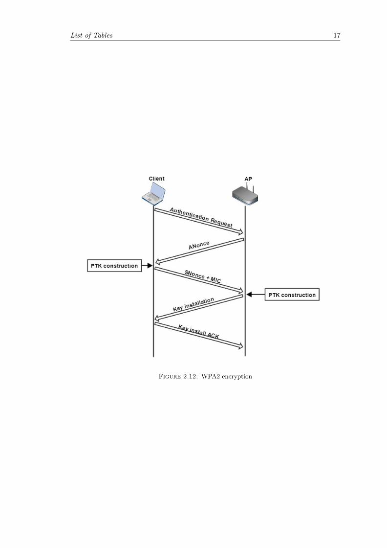
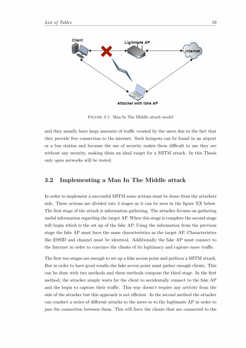
As shown in the Figure 3.1 below, an attacker by using two NICs can bypass the le-
gitimate AP. By broadcasting the same SSID using higher transmission power than the
AP, he is in position to deceive new clients and convince them to connect to the fake
AP. Additionally the attacker is also able to jam and disconnect the clients that are
connected to the legitimate AP and afterwards attract the clients to his own fake AP.
These kind of attacks might fail against a highly protected Wi-Fi network because the
attacker doesn’t know the passphrase and an open network without security might cause
suspicion to the clients. In the other hand Wi-Fi networks with weak security or open
Wi-Fi networks are easy targets for such attacks. Open networks can be found anywhere
18
List of Tables 19
Figure 3.1: Man In The Middle attack model
and they usually have large amounts of traffic created by the users due to the fact that
they provide free connection to the internet. Such hotspots can be found in an airport
or a bus station and because the use of security makes them difficult to use they are
without any security, making them an ideal target for a MITM attack. In this Thesis
only open networks will be tested.
3.2 Implementing a Man In The Middle attack
In order to implement a successful MITM some actions must be dome from the attackers
side. These actions are divided into 4 stages as it can be seen in the figure XX below.
The first stage of the attack is information gathering. The attacker focuses on gathering
useful information regarding the target AP. When this stage is complete the second stage
will begin which is the set up of the fake AP. Using the information from the previous
stage the fake AP must have the same characteristics as the target AP. Characteristics
like ESSID and channel must be identical. Additionally the fake AP must connect to
the Internet in order to convince the clients of its legitimacy and capture more traffic.
The first two stages are enough to set up a fake access point and perform a MITM attack.
But in order to have good results the fake access point must gather enough clients. This
can be done with two methods and these methods compose the third stage. In the first
method, the attacker simply waits for the client to accidentally connect to the fake AP
and the begin to capture their traffic. This way doesn’t require any activity from the
side of the attacker but this approach is not efficient. In the second method the attacker
can conduct a series of different attacks to the users or to the legitimate AP in order to
jam the connection between them. This will force the clients that are connected to the

List of Tables 20
legitimate AP to connect to the fake AP. DESCRIBE THE ATTACKS. Finally the last
stage is to intercept the traffic that is being routed through the fake AP.
Figure 3.2: Man In The Middle attack procedure
3.2.1 Information gathering
The network interfaces(NICs) that operate under the IEEE 802.11x have six modes of
operation. These are Master, Managed, Ad Hoc, Mesh, Repeater and Monitor mode.
In Master mode the NIC acts as an AP and in Managed mode the NIC is acting as a
client to an AP. Ad hoc and Mesh modes are for Ad hoc and mesh networks accordingly
and the Repeater mode re-transmits the Wi-fi signal. In an Wi-Fi network the packets
are being broadcasted by the AP which means that all the clients in range can receive
that broadcast, but the data are delivered to each client based on the destination MAC
address. The rest of the transmitted data, if the destination of the MAC address is
different, are ignored by the clients. In order to monitor all the transmitted data the
NIC must be set to Monitor mode. In this mode the NIC is able to capture all the
data regardless their destination MAC address, making this mode ideal for information
gathering.
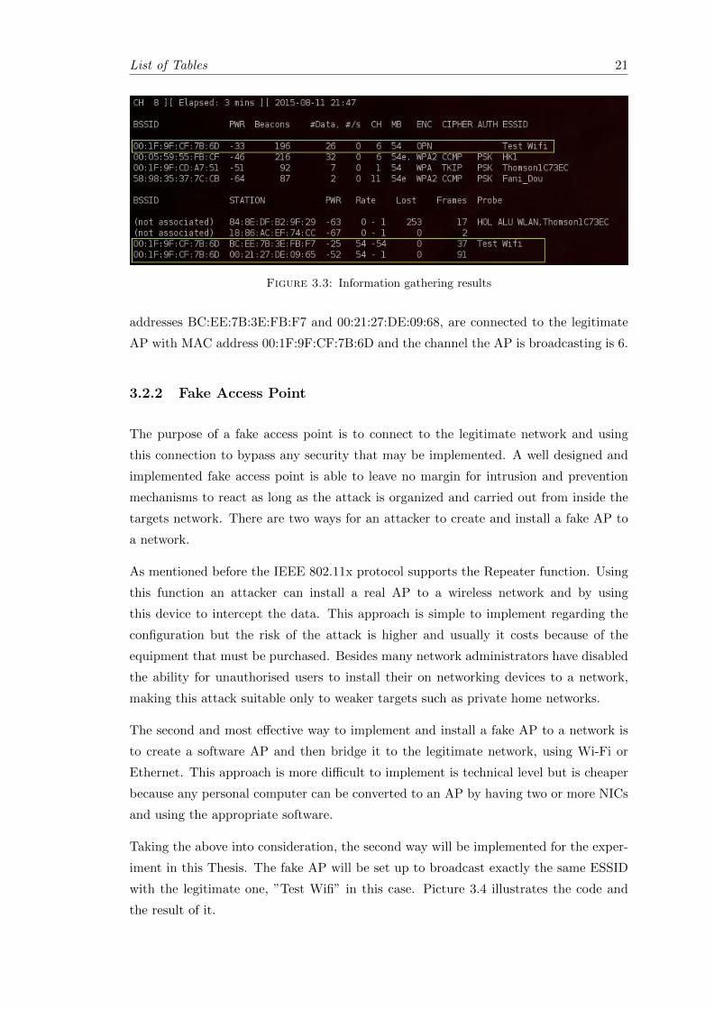
In this Thesis for the implementation of the MITM attack a special distribution of Linux,
named Backtrack 5R3, will be used. In order for the NIC to be set to monitor mode the
airmon-ng command will be used and to begin the information gathering the airmon-ng
command will be used. The Figure 3.3 illustrates the results that occurred during the
reconnaissance.
As it can be sen from the Figure 3.3 every AP chooses its MAC address to be its BSSID
and the ESSID of the target AP is ”Test Wifi”. Additionally two clients, with MAC
List of Tables 21
Figure 3.3: Information gathering results
addresses BC:EE:7B:3E:FB:F7 and 00:21:27:DE:09:68, are connected to the legitimate
AP with MAC address 00:1F:9F:CF:7B:6D and the channel the AP is broadcasting is 6.
3.2.2 Fake Access Point
The purpose of a fake access point is to connect to the legitimate network and using
this connection to bypass any security that may be implemented. A well designed and
implemented fake access point is able to leave no margin for intrusion and prevention
mechanisms to react as long as the attack is organized and carried out from inside the
targets network. There are two ways for an attacker to create and install a fake AP to
a network.
As mentioned before the IEEE 802.11x protocol supports the Repeater function. Using
this function an attacker can install a real AP to a wireless network and by using
this device to intercept the data. This approach is simple to implement regarding the
configuration but the risk of the attack is higher and usually it costs because of the
equipment that must be purchased. Besides many network administrators have disabled
the ability for unauthorised users to install their on networking devices to a network,
making this attack suitable only to weaker targets such as private home networks.
The second and most effective way to implement and install a fake AP to a network is
to create a software AP and then bridge it to the legitimate network, using Wi-Fi or
Ethernet. This approach is more difficult to implement is technical level but is cheaper
because any personal computer can be converted to an AP by having two or more NICs
and using the appropriate software.
Taking the above into consideration, the second way will be implemented for the exper-
iment in this Thesis. The fake AP will be set up to broadcast exactly the same ESSID
with the legitimate one, ”Test Wifi” in this case. Picture 3.4 illustrates the code and
the result of it.

List of Tables 22
Figure 3.4: Code and result of fake AP
As it can be seen from the figure 3.4 above the fake AP has been created using the
the targets ESSID ”Test Wifi”. It also operates in channel ”1” from the NIC mon1. A
virtual interface ”at0” has been created along with the fake AP. This virtual interface
will be used later to connect the fake AP to the Internet. Executing the information
gathering stage again will reveal some useful information.
Figure 3.5: New information gathering results
As illustrated in the Figure 3.5 the fake AP has the same ESSID and operating channel
with the legitimate one. There are two exceptions in the results though. The fake AP
has different BSSID, namely the MAC address, and the transmission power is lower
than that the legitimates transmission power. However spoofing the MAC address of
the legitimate AP is an action that it will be done in the next steps. Additionally the
fake AP can be set up to support security mechanisms like the WEP and WPA/WPA2
but since the target AP has no security mechanism implemented this action is considered
unnecessary.
From the moment the fake AP is created and it is in operational status, the attacker
waits for clients to connect to it. Wi-Fi devices have a mechanism that allow the to
choose their Wi-Fi network automatically. When a Wi-Fi device is turned on it starts
emitting probe requests in order to discover any of the wireless networks that have been
connected in the past. All these network are saved in the PNL(Preferred Network List).
The Wi-Fi device will first search the most used ESSID and then it will continue until the
list is covered. Figure 3.6 illustrates the the probe requests that are transmitted from the
client with MAC address 2C:D0:5A:55:8D:FF. Capturing these probe requests, which are
unencrypted, an attacker can extract many useful information about the client. In Figure
3.6 the client with MAC address 2C:D0:5A:55:8D:FF has been previously connected to
two other networks with ESSIDs ”HK1” and ”Thomson1C73EC” alongside with the
”Test Wifi”.

List of Tables 23
Figure 3.6: Probe Requests
3.2.3 Connecting the Fake Access Point
Implementing a fake AP is not enough to preform a MITM attack. Even users that do
not have advanced networking experience can realise that their connection with the fake
AP is problematic and then they will be disconnected since they won’t be able to access
the Internet. For this reason the fake AP must be connected to an Internet source so it
will be able to provide its clients the desired connection and this way more sensitive data
can be captured. There are two main methods to provide Internet connection through
a fake access point, the Bridged AP and the Routed AP.
3.2.3.1 Bridged Fake Access Point
In Figure 3.7 is illustrated the basic principal of a bridged AP with the target network.
The connection with the target network can be either wired using the Ethernet of wireless
via Wi-Fi. With the establishment of the fake AP an interface 1 is created which is used
by the clients to connect to the fake AP. The second interface, Interface 2, is used to
connect the attacker to the legitimate network and by extension to the Internet. These
two interfaces, Interface 1 and 2, can be bridged providing this way Internet access to
the connected clients.
Figure 3.7: Bridged Access Point

List of Tables 24
The configuration above can be applied to this Thesis test set up. The first Interface can
be replaced with the virtual interface ”at0” that has been created with the AP creation.
Afterwards it can be bridged with the Ethernet interface or with another Wi-Fi interface.
The second option is preferred since it provides greater flexibility and usually there are
no Ethernet port in public Wi-Fi spots for users to connect to.
Figure 3.8: Code for bridged AP
Bridging two interfaces to provide Internet connection to the fake AP might be simple
to implement but it is not stable and secure. Many network and system administrator
add limitation to their AP regarding the connectivity they can provide to other network
devices, like routers and APs. The bridging might be successful but the clients connected
on the fake AP might not get an IP address from the DHCP server of the legitimate
network, leading this approach to failure
3.2.3.2 Routed Fake Access Point
The second method to provide Internet connection to the clients is by using a routed
fake AP during the MITM attack. A routed fake AP can achieve higher reliability and
stability because the traffic is routed on the Network layer in comparison with the bridged
mode where the traffic goes through the Data link layer. For the clients to successfully
connect to the Internet some parameters must be configured. These parameters are
subnet, IP addresses, a subnet mask, a broadcast address, a gateway and a DNS server.
List of Tables 25
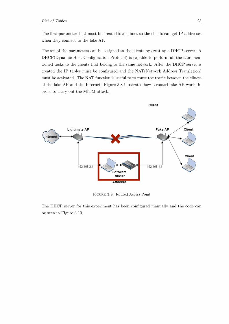
The first parameter that must be created is a subnet so the clients can get IP addresses
when they connect to the fake AP.
The set of the parameters can be assigned to the clients by creating a DHCP server. A
DHCP(Dynamic Host Configuration Protocol) is capable to perform all the aforemen-
tioned tasks to the clients that belong to the same network. After the DHCP server is
created the IP tables must be configured and the NAT(Network Address Translation)
must be activated. The NAT function is useful to to route the traffic between the clinets
of the fake AP and the Internet. Figure 3.8 illustrates how a routed fake AP works in
order to carry out the MITM attack.
Figure 3.9: Routed Access Point
The DHCP server for this experiment has been configured manually and the code can
be seen in Figure 3.10.

List of Tables 26
Figure 3.10: DHCP configuration
Using this configuration the fake AP has a subnet 192.168.1.0 with a subnet mask
255.255.255.0. The gateway’s IP address is 192.168.1.1 and the rang of the IP addresses
the future clients can obtain is from 192.168.1.2 to 192.168.1.50. The DHCP server uses
the domain name ”Test Wifi” and for DNS(Domain Name Server) it is using the gateway
IP address. Since there is no DNS on the attackers machine the clients will request the
domain name from the legitimate AP or from the Internet service provider.
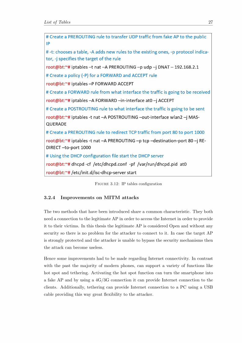
With the DHCP server configured the next step is the configuration of the IP tables.
The code is listed in Figure 3.12
Figure 3.11: Code for routed AP
List of Tables 27
Figure 3.12: IP tables configuration
3.2.4 Improvements on MITM attacks
The two methods that have been introduced share a common characteristic. They both
need a connection to the legitimate AP in order to access the Internet in order to provide
it to their victims. In this thesis the legitimate AP is considered Open and without any
security so there is no problem for the attacker to connect to it. In case the target AP
is strongly protected and the attacker is unable to bypass the security mechanisms then
the attack can become useless.
Hence some improvements had to be made regarding Internet connectivity. In contrast
with the past the majority of modern phones, can support a variety of functions like
hot spot and tethering. Activating the hot spot function can turn the smartphone into
a fake AP and by using a 4G/3G connection it can provide Internet connection to the
clients. Additionally, tethering can provide Internet connection to a PC using a USB
cable providing this way great flexibility to the attacker.

List of Tables 28
3.3 Manipulating the Clients
Thus far the fake AP has been created and the clients can access the Internet through it.
Although the fake access point has the same characteristics with the target, some users
might still be connected to the legitimate one. To increase the success of the attack the
attacker needs to attract more clients to the fake AP in order to intercept more data.
To do so a series of attacks have to take place in order to disconnect the clients fron the
target AP and then force them to connect to the fake one.
3.3.1 Jamming Attacks
Jamming attacks are a DoS(Denial of Service) type attack. DoS attacks in general aim
to make a machine or a network unavailable to the users and in this scenario the target
is the legitimate AP. Jamming attacks can be launched using one of the two methods.
The attacker can dramatically increase the noise in the receiver by generating a high
power signal in the same frequency the channel operates. This will cause the corruption
of the transmitted data and the receiver will not be able to demodulate the incoming
information or correct the errors. Therefore all the corrupt received information will be
discarded. In the second method the attacker can transmit packets without following
any access mechanism in the channel. These packets can have valid frame header with
useless payload and thus they might be mistakenly considered as valid from the receiver.
Bypassing the access mechanisms the attacker can deceive other clients in the network
that a legitimate transmission is taking place using the aforementioned packets. As long
as the attacker transmits these packets the channel will become unavailable and the
access to the clients will be denied[9].
Each jamming attack follows a different strategy to attack the target. Some of these
attacks are less effective than other thus they have been grouped in to four models:
Constant jamming model, Deceptive jamming model, Random jamming model, Reactive
jamming model.
1. Constant Jamming model: In this model the attacker transmits random useless
data to the channels without obeying any access channel mechanisms in the net-
work. When another client attempts to gain access to the channel it finds it busy
and thus it backs off according to the CSMA mechanism. When repeated back
offs occur the client will be forced to disconnect from the network.
2. Deceptive Jamming model: Like the Constant Jamming model this model also
follows the same strategy. It continuously transmits useless and random data but

List of Tables 29
with a valid frame header. It doesn’t follow any channel access mechanism and
the frames simulate a valid transmission. The rest of the clients are deceived by
this transmission and they initiate the back off mechanism in order to access the
channel when it will become available.
3. Random jamming model: In this model the transmission happens in random pe-
riods for a pre-specified time and then the jammer enter sleep mode. The trans-
missions can be either Constant like or Deceptive like. This model is efficient
regarding energy consumption in comparison with the previous two, but it has the
disadvantage that it might operate when there is no traffic to jam.
4. Reactive jamming model: In this model the jammer is initially suspended and it
is sensing the channel. When a transmission is detected it initiates the jamming
following a Constant like or Deceptive like approach. When the transmission is
jammed and there is no more clients transmitting it goes back to its initial state.
This model is also energy efficient and it is harder for to detect.
In order to define the most efficient model for the MITM thwo metrics where introduced:
PSR(Packet Send Ratio) and the PDR(Packet Delivery Ratio).
1. The PSR indicates the ratio of the packets that have been transmitted out of the
total number of the packets that where indented to be transmitted. This metric
can only be calculated in the transmitter.
2. The PDR indicate the ratio of packets that have been successfully delivered to
their destination in comparison with the total packets that have been sent by
the transmitter. This metric can be calculated by both the transmitter and the
receiver. The receiver can calculate the ratio by comparing the successfully read
packets with the total received packets. The transmitter can calculate the ratio
using the ACKs that the receiver sends for every packet received.
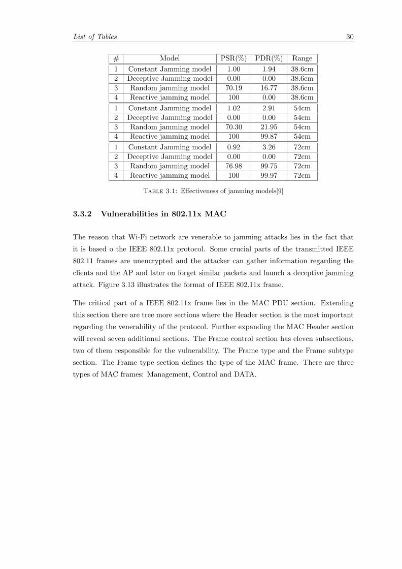
The effectiveness of the jamming models can be seen in the table 3.1 In short range all
the jamming models achieve good performance regarding the PDR which is reduced dra-
matically. The Constant and the Deceptive models achieve good performance regarding
the PSR in contrast with the rest of the models where their performance it is not that
effective. There are similar results for the medium and the long range tests where all
models behave like the first one. Only the Deceptive jamming model achieves a clear
zero percent though, and thus it will be the strategy where the MITM will be based on.
List of Tables 30
# Model PSR(%) PDR(%) Range
1 Constant Jamming model 1.00 1.94 38.6cm
2 Deceptive Jamming model 0.00 0.00 38.6cm
3 Random jamming model 70.19 16.77 38.6cm
4 Reactive jamming model 100 0.00 38.6cm
1 Constant Jamming model 1.02 2.91 54cm
2 Deceptive Jamming model 0.00 0.00 54cm
3 Random jamming model 70.30 21.95 54cm
4 Reactive jamming model 100 99.87 54cm
1 Constant Jamming model 0.92 3.26 72cm
2 Deceptive Jamming model 0.00 0.00 72cm
3 Random jamming model 76.98 99.75 72cm
4 Reactive jamming model 100 99.97 72cm
Table 3.1: Effectiveness of jamming models[9]
3.3.2 Vulnerabilities in 802.11x MAC
The reason that Wi-Fi network are venerable to jamming attacks lies in the fact that
it is based o the IEEE 802.11x protocol. Some crucial parts of the transmitted IEEE
802.11 frames are unencrypted and the attacker can gather information regarding the
clients and the AP and later on forget similar packets and launch a deceptive jamming
attack. Figure 3.13 illustrates the format of IEEE 802.11x frame.
The critical part of a IEEE 802.11x frame lies in the MAC PDU section. Extending
this section there are tree more sections where the Header section is the most important
regarding the venerability of the protocol. Further expanding the MAC Header section
will reveal seven additional sections. The Frame control section has eleven subsections,
two of them responsible for the vulnerability, The Frame type and the Frame subtype
section. The Frame type section defines the type of the MAC frame. There are three
types of MAC frames: Management, Control and DATA.

List of Tables 31
Figure 3.13: structure of a 802.11 frame 1/2

List of Tables 32
1. Management Frames: Management frames enable the nodes to establish communi-
cation between them. The can be divided into many different subtypes defined by
the Frame subtypes section. Picture 3.14 illustrates eight of the possible manage-
ment subtypes: Association request, Association response, Probe request, Probe
response, Beacon, Disassociation and De-authentication. These subtypes are re-
sponsible for the initialisation and the termination of the communication between
the client and the AP.
2. Control Frames: Control frames are responsible for the data exchange between
the client and the AP. In picture 3.14 three types of the control frames are illus-
trated, RTS, CTS and ACK. The control frames are used by the channels access
mechanism.
3. Data Frames: Data frames contain the data that are meant to be transmitted.
These frames are encrypted when a security mechanism is active on the network.
Figure 3.14: structure of a 802.11 frame 2/2
The fact that only the Data frames can be encrypted reveal the vulnerability of the IEEE
802.11 protocol. The rest of the frames can reveal private information to the attacker,
as it happen in the information gathering section, and also the attacker can forge fake
frames in order to launch a series of attacks. The reason that there is no encryption to
the rest of the frames lies on the fact that if the rest of the frames where encrypted all
the network devices would be forced to consume a significant amount of their resources
in order to encrypt and decrypt these frames. There is a very large volume of these
List of Tables 33
frames during a network session and the process of encryption and decryption would
reduce the the overall performance of the network.
3.3.3 Connection and disconnection process
When a user activates a Wi-fi device, the device begins a sequence of actions in order to
connect to an AP. The first step in this process is to discover the AP and synchronise
with it. There are two ways to achieve that: Passive scanning and Active scanning.
1. Active scanning: During the active scanning the client will transmit a probe re-
quest and then wait for a probe response from the AP.
2. Passive scanning: During the passive scanning the client listen in every channel
for a Beacon frame sent by the AP. When this Beacon frame is received the client
initiates the connection. This approach is much slower that the active one because
the client must wait for the AP to send the Beacon frame and there is a possibility
that the client will miss the Beacon frame if it is transmitted in an other channel
When the client discovers the AP and decides to connect to it, a three stage process
begins. In stage one the state of the client is Unauthenticated and Unassociated and
the client transmits to the AP an Authentication request frame. The AP will respond
by transmitting an Authentication response to the client. If there is an active security
mechanism the authentication response will be sent only if the credentials of the client
are correct. The client enter the second stage where its state is Authenticated and
Unassociated. Next the client will transmit to the AP an Association request. The AP
will respond with an Association response. This is the third stage where the state of the
client is Authenticated and Associated.

List of Tables 34
Figure 3.15: Connection process
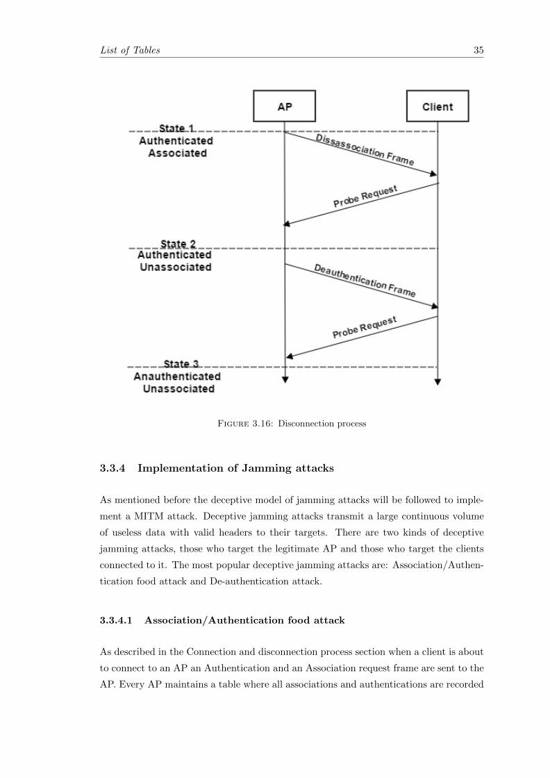
The reversed procedure will disconnect a client from an AP. Initially the client is Associ-
ated and Authenticated. The AP will transmit a Dissacossiation frame to the client and
the client will respond with a Probe request. This will change the state of the client to
Unassociated and Authenticated. Next the AP will transmit a Deauthentication frame
to the client and client will respond again with a Probe request. Finally the client’s
state will change to Unassociated and Unauthenticated.
List of Tables 35
Figure 3.16: Disconnection process
3.3.4 Implementation of Jamming attacks
As mentioned before the deceptive model of jamming attacks will be followed to imple-
ment a MITM attack. Deceptive jamming attacks transmit a large continuous volume
of useless data with valid headers to their targets. There are two kinds of deceptive
jamming attacks, those who target the legitimate AP and those who target the clients
connected to it. The most popular deceptive jamming attacks are: Association/Authen-
tication food attack and De-authentication attack.
3.3.4.1 Association/Authentication food attack
As described in the Connection and disconnection process section when a client is about
to connect to an AP an Authentication and an Association request frame are sent to the
AP. Every AP maintains a table where all associations and authentications are recorded

List of Tables 36
and stored. Exceeding the limits of this table will cause serious problems to the AP
regarding its communication with the clients.
The first attack that can achieve such a result is the authentication flood attack. The
attacker can send thousands of fake authentications using random fake MAC addresses
to the AP and after a while, depending on the injection rate, the table will reach its
limit. This action will force the AP to reject ant new clients trying to connect. Further
usage of the attack can cause the AP to disconnect the existing clients or depending on
the manufacturer, reset the AP it self. A powerful tool to perform an authentication
flood attack is the MDK3 found in Linux systems. In figure 3.17 is illustrated the process
of the attack in theory and in picture 3.18 the attack is launched to the ”Test Wifi”
network.
Figure 3.17: Authentication flood process

List of Tables 37
Figure 3.18: code to conduct authentication flood attack
Figure 3.19: Authentication flood attack in progress
Like the Authentication flood attack the Association flood attack follows the same prin-
cipals. The attacker can flood the target with forged association frames aiming to
overflow the Association table. Once the Association table is full the AP will not be
able to connect any new clients and it will begin disconnecting the already connected.
Despite that both attacks have the same strategy regarding the attack itself, the Asso-
ciation flood attack has some disadvantages. In contrast with the past all the AP have
installed mechanisms that prevent the Association flood attack to take place. APs can
distinguish if the incoming association frames are from a valid client by checking the
Association table for a previous valid authentication. If there is not a valid authentica-
tion present they are discarded. Additionally many APs have integrated serial number
counters and they can monitor the serial number of the frames. Once they discover
irregular arrival of incoming association frames they are discarded automatically.
3.3.4.2 De-authentication attack
Both the Authentication flood attack and the Association flood attack are aiming at the
legitimate APs to disconnect their clients. But, as mentioned in the previous section,
there are cases that these attacks will fail to disconnect the clients from the legitimate

List of Tables 38
APs due to defensive mechanisms like the Serial Number counter regarding the associ-
ation frames. The De-authentication attack can cover that failure because it has the
ability to attack the clients that are connected to the target AP by sending large volumes
of forged de-authentication frames to them. The receiving clients consider these frames
valid and thus they stay unauthenticated.
Figure 3.20: Deuthentication process
The De-authentication attack can operate in unicast mode and disconnect a certain
client connected on the target AP. To increase the efficiency of the attack it can operate
in broadcast mode. In this mode the attacker transmit forged de-authentication frames
to all the clients that are connect to the target AP and will force them to retreat to
Unauthenticated/Unassociated state. In this occasion the attacker can lure the clients
to connect to the fake AP and start intercepting their traffic. The tood that can conduct
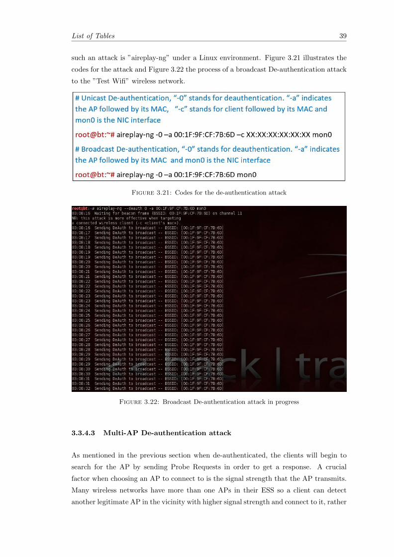
List of Tables 39
such an attack is ”aireplay-ng” under a Linux environment. Figure 3.21 illustrates the
codes for the attack and Figure 3.22 the process of a broadcast De-authentication attack
to the ”Test Wifi” wireless network.
Figure 3.21: Codes for the de-authentication attack
Figure 3.22: Broadcast De-authentication attack in progress
3.3.4.3 Multi-AP De-authentication attack
As mentioned in the previous section when de-authenticated, the clients will begin to
search for the AP by sending Probe Requests in order to get a response. A crucial
factor when choosing an AP to connect to is the signal strength that the AP transmits.
Many wireless networks have more than one APs in their ESS so a client can detect
another legitimate AP in the vicinity with higher signal strength and connect to it, rather

List of Tables 40
than the fake AP. In order to face this problem the attacker must have a high power
transmitter so that the fake AP’s transmitted signal will overcome all the legitimate ones.
Additionally, in order to avoid any client migration to other legitimate APs, the attacker
will have to attack the rest of the APs. Performing a multi-AP de-authentication attack
to the all the clients, the attacker will leave no choice to the clients but to connect to
the fake AP.
In a multi-AP environment the attacker will face the challenge of confronting several
legitimate APs in the same time. Performing the usual de-authentication attack as
described in a previous section is not a viable and efficient solution, especially when
the number of APs are more than two. For that reason the attack has to be based
on a system that will attack all the APs in the same time based on a list. During
the information gathering process the attacker will mark the target APs and create a
blacklist with their BSSID. Later on this list will be passed to the attacking tool along
with a list of rules regarding the attack. The rules list will include allow and deny rules
regarding the targeted APs and clients along with the fake AP. To conduct the multi-AP
de-authentication attack the ”Airdrop-ng” tool was used under Linux environment.
After performing an Information gathering, more than one APs where discovered by the
attacker in the vicinity. Figure 3.23 the results of the operation.
Figure 3.23: Information gathering with multiple results
The APs with BSSIDs 00:1C:A8:0A:98:FF and 00:1F:9F:CF:7B:6D are target APs and
they both have a connected client to them with MAC addresses 00:21:27:DE:09:65
and BC:EE:7B:3E:FB:F7 accordingly. Additionally the Fake AP can be seen with
BSSID E8:4E:06:0A:02:B0 having the same ESSID with the target APs. In order to
de-authenticate the clients from the target APs, the target APs must be blacklisted in
the rules list. The rules can be seen in figure 3.24
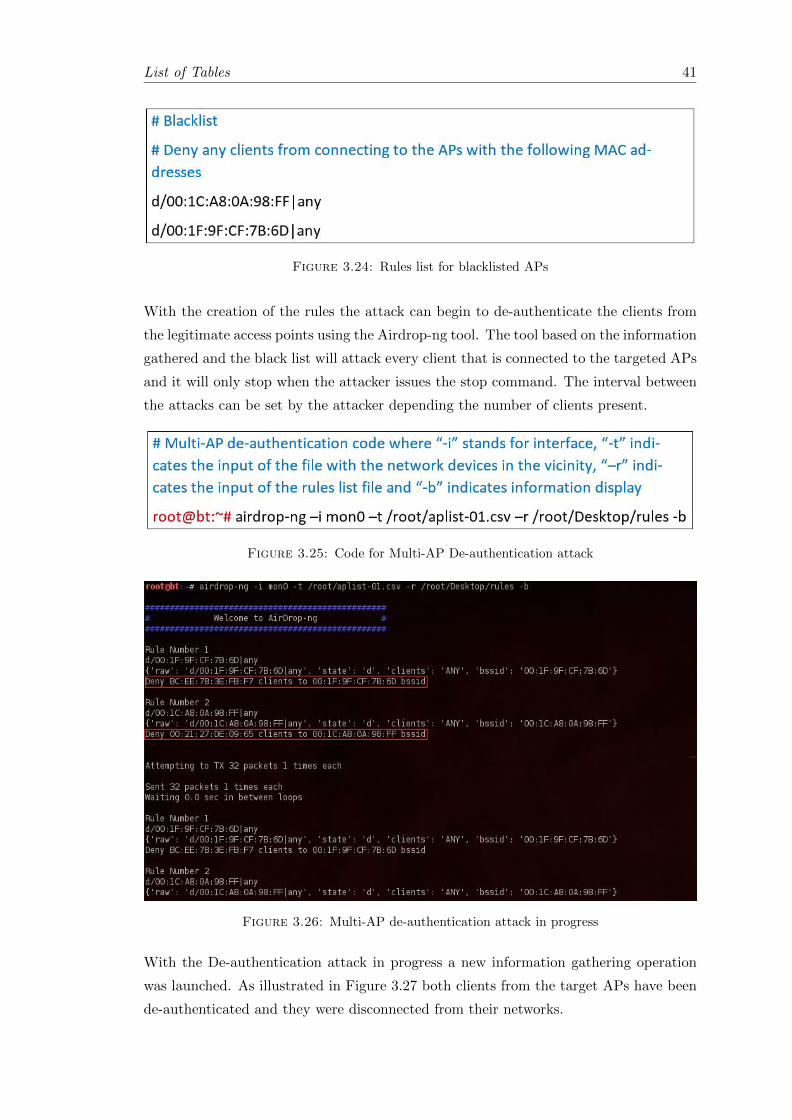
List of Tables 41
Figure 3.24: Rules list for blacklisted APs
With the creation of the rules the attack can begin to de-authenticate the clients from
the legitimate access points using the Airdrop-ng tool. The tool based on the information
gathered and the black list will attack every client that is connected to the targeted APs
and it will only stop when the attacker issues the stop command. The interval between
the attacks can be set by the attacker depending the number of clients present.
Figure 3.25: Code for Multi-AP De-authentication attack
Figure 3.26: Multi-AP de-authentication attack in progress
With the De-authentication attack in progress a new information gathering operation
was launched. As illustrated in Figure 3.27 both clients from the target APs have been
de-authenticated and they were disconnected from their networks.

List of Tables 42
Figure 3.27: De-authenticated clients
From the moment the clients are de-authenticated and disconnected from the legitimate
APs the will automatically begins sending Probe Requests trying to re-connect to the
network. With the legitimate APs being jammed the only option for the clients is the
Fake AP that it has been set up with the same ESSID. The clients will not realise that
they are under attack and the migration from the legitimate AP to the fake AP will last
some seconds. The results of the attack are illustrated in Figure 3.28 where the client
with MAC address 00:21:27:DE:09:65 automatically connected to the Fake AP.
Figure 3.28: De-authenticated client an the Fake AP
3.4 Traffic interception
With the successful implementation of the MITM attack the attacker is now able to
intercept the routed traffic passing through the fake AP, namely the attacker’s computer.
There are plenty of tools available to perform the task such as Wireshark and Tcpdump
but the purpose of a MITM attack is to capture the sensitive information the clients
send and receive thought the network rather than the whole traffic. The majority of the
websites that require credentials from the client, like on-line banking and social media,
they usually protect their session using the Hypertext Transfer Protocol Secure(HTTPS)
protocol. Any captured HTTPS frames will require extra workload from the attackers
side in order to decrypt those frames and retrieve the information. The MITM attack
gives the opportunity to the attacker to intercept those credentials without decrypting
any HTTPS frames at all.
With the aim to intercept only the valuable data from the traffic a set of tools will be
used, the combination of ettercap and sslstrip. Ettercap is a tool that it is used for

List of Tables 43
network protocol analysis and it is capable to intercept traffic as well as conduct active
eavesdropping on a number of protocols. Ettercap has four modes of operation: IP-
mode, MAC-mode, ARP-mode and PublicARP-mode. In this experiment the IP mode
will be used and all the traffic from the virtual interface at0 will be intercepted.
The second tool used in the experiment, as mentioned before, is Sslstrip. Sslstrip is a
tool that prevents a web browser to upgrade its regular connection to an SSL protected
connection. Additionally Sslstrip creates a fake valid certificate mimicking the target
web server the client is trying to connect to. With this way the browser is deceived that
the connection is secure and there is no warning that the session is hijacked. Picture
3.29 illustrates the implementation of Ettercap and Sslstrip tool in the MITM attack.
Figure 3.29: Ettercap and Sslstrip implemetation
First the Sslstrip tool needs to be implemented in order to deny any secure sessions to
the connected clients and afterwards the Ettecap tool to intercept the traffic. Figures
3.30 and 3.31 illustrate the necessary codes.
Figure 3.30: Code for Sslstrip
With both tools active and ready the attacker is now able to intercept any valuable
data from the clients in real time. To demonstrate the effectiveness of the attack the
connected client attempts to access the web-page https://www.facebook.com using as
user name ”[email protected]” and as password ”testpass”. Figure 3.32 and figure
3.33 illustrate Sslstrip and Ettercap in action.

List of Tables 44
Figure 3.31: Code for Ettercap
Figure 3.32: Sslstrip in progress

List of Tables 45
Figure 3.33: Captured credentials with Ettercap
As it can be seen from Figure 3.33 the combination of Sslstrip and Ettercap was suc-
cessful. The attacker was able to get the username and the password from the client
without interrupting the connection or notifying the client about the insecure session.
There are many potentials in favor of the attacker in a successful MITM attack. The
aforementioned experiment is one of the many option that are available to implement.
There are other forms of session hijacking that can take place under a MITM attack.
The attacker can forge a website infected with viruses and malicious software and by
manipulating the DNS can direct the clients to it while they are requesting another
website. In this case the clients computers will be infected and they will give the attacker
the capability to steal more information or even take control the clients computers.

Chapter 4
Design of Detection and
Prevention System
4.1 Introduction
The goal of this chapter is to design and implement a system that it will be able to to
detect and actively prevent a Man In the Middle Attack. Based on the research, the
implementation and the results from the MITM described in Chapter 3, the attacker to
successfully conduct a MITM attack uses deceptive methods and a series of attacks to the
legitimate APs to acquire their clients. Nowadays many network equipment manufactur-
ers have implemented mechanisms to their APs that prevent the attacker to effectively
disrupt the operation of their products. Such an example are the mechanisms that pre-
vent the Association flood attack and Authentication flood attack. As described before
both the Association and Authentication flood attack can be prevented by establishing
a counter that observes the incoming association and authentication frames.
Given the fact that the aforementioned attacks can be prevented, the most effective way
to disconnect the clients from the network they are attached to, is to attack them by
using the De-authentication attack. Due to the lack of encryption in the MAC frames
this kind of attack cannot be prevented using non specialized wireless equipment. This
means that the clients are completely exposed to the attacker and the attacker cannot
be discovered when launching the attack.
Despite the inability to prevent the De-authentication attack without the use of spe-
cialised and expensive equipment, the success of a MITM attack lies on the creation
of the fake AP. As mentioned before a fake AP with the same characteristics as the
legitimate ones can deceive the future clients and provide access to them without the
46
List of Tables 47
need to perform any attack. By creating a regular AP the attacker cannot earn the trust
of the users and thus the MITM attack will not be successful.
Based on those considerations, to successfully detect and prevent any possible MITM
the future system will have to first identify the existence of any possible fake APs in
the are of interest and secondly prevent the users to connect to it. The system will be
designed in such a manner that it will be able to detect any fake APs based on their
attributes and then give the options to the network administrators to define their actions
in order to neutralise the threat. Such a system however requires the ability to collect
a series of metrics to achieve the desired result. The metrics that are needed are:
1. BSSIDs: To determine if an AP is fake based on the BSSID
2. SSIDs: To determine if an AP is fake based on the broadcasted SSID
3. Transmission Power: Required to determine if an AP with identical BSSID and
SSID is fake.
4. Broadcast Channel: Required for the same reason as before
5. Security Mechanism: Required for the same reason as before
6. Cypher Method: Required for the same reason as before
7. Authentication method: Required for the same reason as before
The aforementioned metrics will be used to distinguish the legitimate APs from the
fake one. A fake AP can have the same BSSID and ESSID with a legitimate one and
therefore the additional metrics can be used to make the distinction. The attacker can
mimic the majority of the metrics since they are broadcasted by the legitimate APs but
it is impossible to know the parameters set by an independent security system regarding
the maximum and the minimum transmission power of a legitimate AP.
The metrics of the legitimate APs will form a protection list which it will be stored
in a database under the detection and protection system. Then based on this list the
system will regularly scan the vicinity for any changes comparing the results with the
stored list. If a new AP is detected and it is absent from the protection list it will be
considered as an attempt to perform a MITM attack. Finally after the detection of the
fake AP the prevention mechanism will automatically begin a de-authentication attack
to the fake AP in order to prevent any clients from connecting to it.
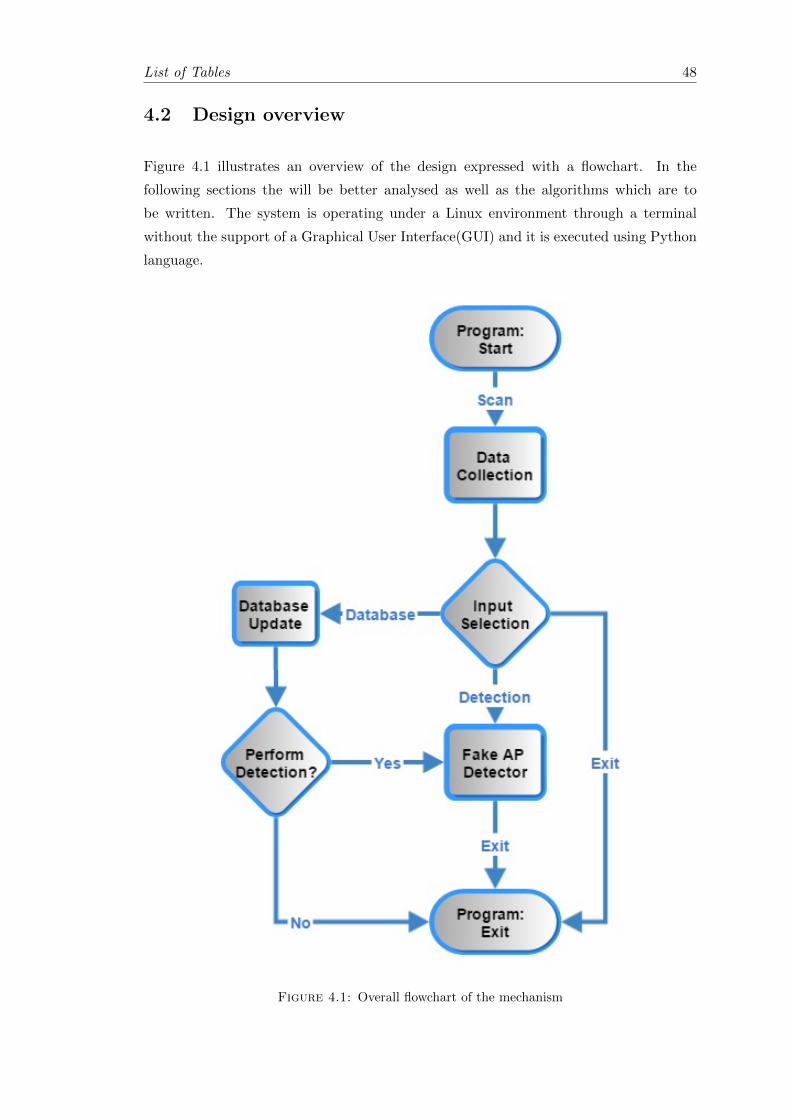
List of Tables 48
4.2 Design overview
Figure 4.1 illustrates an overview of the design expressed with a flowchart. In the
following sections the will be better analysed as well as the algorithms which are to
be written. The system is operating under a Linux environment through a terminal
without the support of a Graphical User Interface(GUI) and it is executed using Python
language.
Figure 4.1: Overall flowchart of the mechanism

List of Tables 49
The program consists of three modules: Data collection, Database Update and Fake
AP detector. The system can be terminated either by user interference or when the
requested operations are completed. It has the ability to perform a fake AP detection
based on the stored protection list or update its database and the perform a detection
using the updated information. Additionally it can operate without performing any
detection by choosing to update the database only. The next subsection will describe
the operation of the ”Data Collection” module and all its sub processes.
4.2.1 Data Collection
This subsection describes the Data Collection module and all the processes it includes.
Figure 4.2 shows the over all flowchart of the module. The very first step of the module is
to initialise the database where the protection list will be created. With the completion
of the database creation the module then initializes checks the database to identify if
there are any de-authentication options store. If the System runs for the first time the
default options are stored in the database. In case the programme has been operated
before the module loads any previous options. Completing this operation the module
activates the wireless NIC and sets it to operate in Monitor mode. This way the NIC
will be able to to receive all the transmitted data from the surrounding APs.
By setting the NIC in Monitor mode the module then initiates a scan using the airodump-
ng tool in order to discover any active wireless devices operating under 802.11x in the
are of interest. The results of the scan are processed through the filters for evaluation.
In this stage the module separates any discovered clients from the results and keep only
the discovered APs. When the results filtering is finished the module will store all the
necessary information and finally it displays the filtered results from the scan.
Figure 4.2: Flowchart of the Data Collection module

List of Tables 50
The module will filter and extract the metrics that were mentioned in the introduction
of this chapter:
1. BSSIDs: The MAC addresses of the transmitting APs.
2. SSIDs: The Wi-Fi broadcasted names in the vicinity.
3. Maximum Transmission Power: The transmitting power of every AP.
4. Broadcast Channel: The channel that every AP is transmitting.
5. Security Mechanism: The security mechanism for every transmission, if any.
6. Cypher Method: The Cypher method of the security mechanism.
7. Authentication method: The authentication method of each security mechanism.
Later on the filtered results of the scan will be passed to the Database Update module in
order for the database to be updated or to the Fake AP Detectors to detect the existence
of any possible fake APs in the area.
4.2.2 Database Update
The database Update module is responsible for updating the database upon user request.
The whole system doesn’t interfere with the database except in the initialisation part.
With the filtered results ready the system displays to the user any protected APs in the
database. The user is then prompted to make a selection. Four out of the six available
selections available are database related. Based on the results the user can add an AP
to the protection list.
The additions to the protection list can be made with two ways. The first way is to
select any available SSID that is delivered from the Filtered results. Since the SSID is
selected the module will automatically add to the protection list all the APs that are
transmitting using the selected SSID. The second way to add an AP to the protection
list is to manually select the BSSID, namely the MAC address, of every access point in
the filtered results.
The third option given to the user by the module is the removal of an AP. The process
is similar to the second option. The removal of the selected AP is based on the BSSID
in order to prevent any mass deletion in the protected list. Finally the fourth gives the
user the option to alter the de-authentication parameters in the system. As mentioned
in the previous subsection, with the initialisation of the system the de-authentication
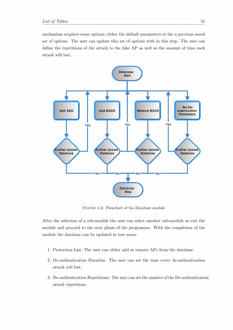
List of Tables 51
mechanism acquires some options, either the default parameters or the a previous saved
set of options. The user can update this set of options with in this step. The user can
define the repetitions of the attack to the fake AP as well as the amount of time each
attack will last.
Figure 4.3: Flowchart of the Database module
After the selection of a sub-module the user can select another sub-module or exit the
module and proceed to the next phase of the programme. With the completion of the
module the database can be updated in tree areas:
1. Protection List: The user can either add or remove APs from the database.
2. De-authentication Duration: The user can set the time every de-authentication
attack will last.
3. De-authentication Repetitions: The user can set the number of the De-authentication
attack repetitions.
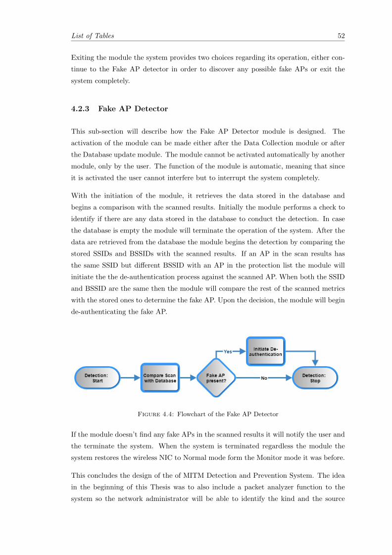
List of Tables 52
Exiting the module the system provides two choices regarding its operation, either con-
tinue to the Fake AP detector in order to discover any possible fake APs or exit the
system completely.
4.2.3 Fake AP Detector
This sub-section will describe how the Fake AP Detector module is designed. The
activation of the module can be made either after the Data Collection module or after
the Database update module. The module cannot be activated automatically by another
module, only by the user. The function of the module is automatic, meaning that since
it is activated the user cannot interfere but to interrupt the system completely.
With the initiation of the module, it retrieves the data stored in the database and
begins a comparison with the scanned results. Initially the module performs a check to
identify if there are any data stored in the database to conduct the detection. In case
the database is empty the module will terminate the operation of the system. After the
data are retrieved from the database the module begins the detection by comparing the
stored SSIDs and BSSIDs with the scanned results. If an AP in the scan results has
the same SSID but different BSSID with an AP in the protection list the module will
initiate the the de-authentication process against the scanned AP. When both the SSID
and BSSID are the same then the module will compare the rest of the scanned metrics
with the stored ones to determine the fake AP. Upon the decision, the module will begin
de-authenticating the fake AP.
Figure 4.4: Flowchart of the Fake AP Detector
If the module doesn’t find any fake APs in the scanned results it will notify the user and
the terminate the system. When the system is terminated regardless the module the
system restores the wireless NIC to Normal mode form the Monitor mode it was before.
This concludes the design of the of MITM Detection and Prevention System. The idea
in the beginning of this Thesis was to also include a packet analyzer function to the
system so the network administrator will be able to identify the kind and the source

List of Tables 53
of an attack that aims the router. For the reasons explained in the introduction of
the chapter creating such a mechanism would significantly add more workload to the
system’s host for the detection of some attacks that are not efficient. Additionally
detecting any de-authentication frames wouldn’t add any significant advantage thus the
idea was abandoned.

Chapter 5
Implementation of Detection and
Prevention System
5.1 Introduction
This chapter includes the implementation of the system and it’s modules designed in
chapter 4 to detect and prevent a MITM attack. The modules of the system have been
implemented using Pyhton language under a Linux environment. The structure of the
system implementation will follow the the design structure presented in the previous
chapter. Additionally code listings will be included for explanatory purposes. Explana-
tion and reasoning for every code listing will follow in every presented module during
the system implementation.
5.2 Data Collection
As described in chapter 4 the first step in the Data collection module is to initialise or
create a database where the metrics will be stored. This step is crucial to the system
because the Detectors ability to find fake APs lies in the stored data of the database.
Without an active database the System will only operate as an observer of the surround-
ing access points. For simplicity reasons MySQL server has the default username and
password as well as the default host IP address.
The connect to the database the MySQLdb.connect Python module is used and then
it is passed to the dbconnection. Later on, on line 25 the dbconnection is aligned
with the cursor class. The cursor class allows Python language to run SQL commands
in a database session. They are bounded to the SQL connection for the whole duration
54
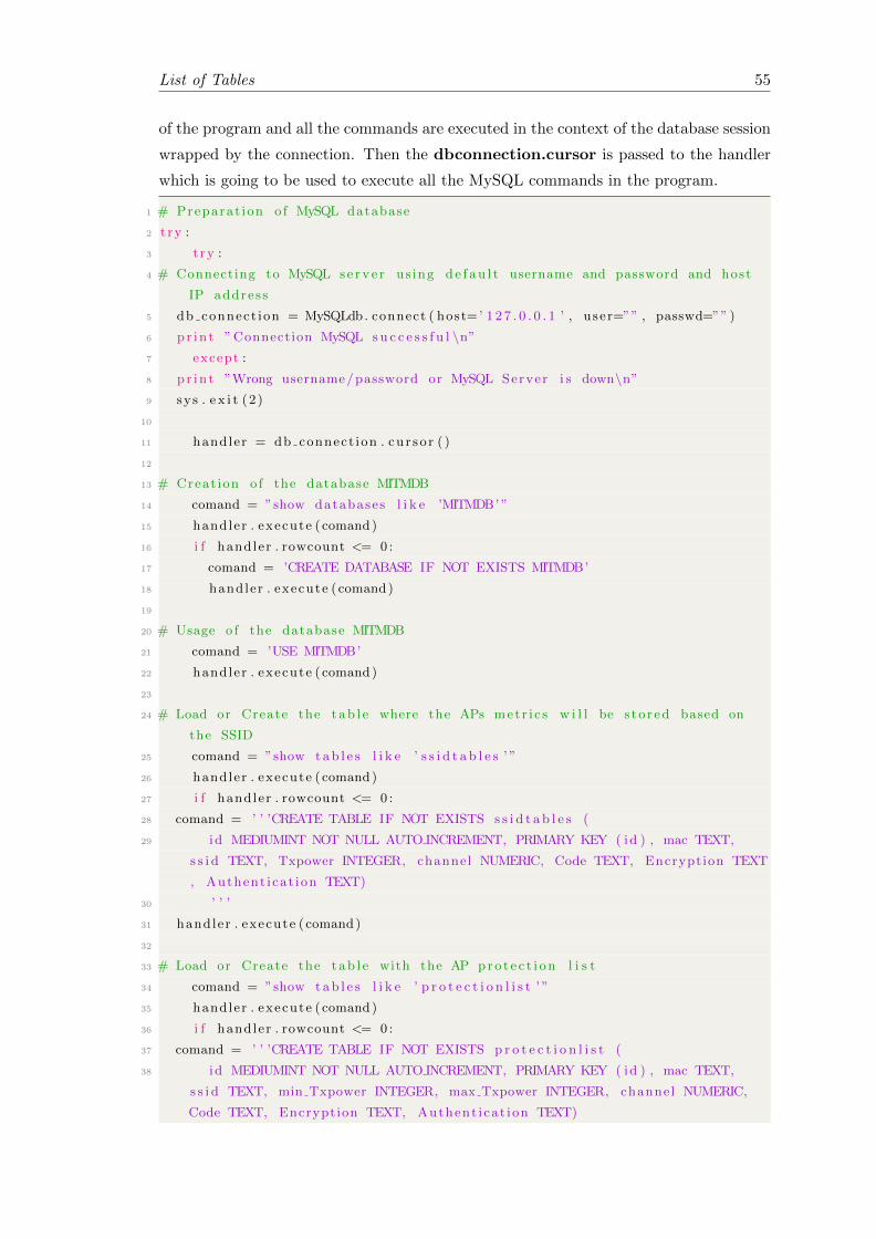
List of Tables 55
of the program and all the commands are executed in the context of the database session
wrapped by the connection. Then the dbconnection.cursor is passed to the handler
which is going to be used to execute all the MySQL commands in the program.
1 # Preparat ion o f MySQL database
2 t ry :
3 t ry :
4 # Connecting to MySQL se rv e r us ing d e f au l t username and password and host
IP address
5 db connect ion = MySQLdb. connect ( host=’ 1 2 7 . 0 . 0 . 1 ’ , use r=”” , passwd=”” )
6 pr in t ”Connection MySQL s u c c e s s f u l \n”7 except :
8 pr in t ”Wrong username/password or MySQL Server i s down\n”9 sys . e x i t (2 )
10
11 handler = db connect ion . cu r so r ( )
12
13 # Creat ion o f the database MITMDB
14 comand = ”show databases l i k e ’MITMDB’ ”
15 handler . execute ( comand)
16 i f handler . rowcount <= 0 :
17 comand = ’CREATE DATABASE IF NOT EXISTS MITMDB’
18 handler . execute ( comand)
19
20 # Usage o f the database MITMDB
21 comand = ’USE MITMDB’
22 handler . execute ( comand)
23
24 # Load or Create the t ab l e where the APs metr i c s w i l l be s to r ed based on
the SSID
25 comand = ”show tab l e s l i k e ’ s s i d t a b l e s ’ ”
26 handler . execute ( comand)
27 i f handler . rowcount <= 0 :
28 comand = ’ ’ ’CREATE TABLE IF NOT EXISTS s s i d t a b l e s (
29 id MEDIUMINT NOT NULL AUTO INCREMENT, PRIMARY KEY ( id ) , mac TEXT,
s s i d TEXT, Txpower INTEGER, channel NUMERIC, Code TEXT, Encryption TEXT
, Authent icat ion TEXT)
30 ’ ’ ’
31 handler . execute ( comand)
32
33 # Load or Create the t ab l e with the AP pro t e c t i on l i s t
34 comand = ”show tab l e s l i k e ’ p r o t e c t i o n l i s t ’ ”
35 handler . execute ( comand)
36 i f handler . rowcount <= 0 :
37 comand = ’ ’ ’CREATE TABLE IF NOT EXISTS p r o t e c t i o n l i s t (
38 id MEDIUMINT NOT NULL AUTO INCREMENT, PRIMARY KEY ( id ) , mac TEXT,
s s i d TEXT, min Txpower INTEGER, max Txpower INTEGER, channel NUMERIC,
Code TEXT, Encryption TEXT, Authent i cat ion TEXT)

List of Tables 56
39 ’ ’ ’
40 handler . execute ( comand)
41
42 # Load or Create the t ab l e where the De−authen t i c a t i on a t t r i b u t e s are
s to r ed
43 comand = ”show tab l e s l i k e ’ a t r i b u t e s ’ ”
44 handler . execute ( comand)
45 i f handler . rowcount <= 0 :
46 comand = ’ ’ ’CREATE TABLE IF NOT EXISTS a t r i bu t e s (
47 op t i o n i nd i c varchar (255) , o p t i o n va r i a b l e varchar (255) )
48 ’ ’ ’
49 handler . execute ( comand)
50
51 # Empties the t ab l e s s i d t a b l e s
52 comand = ’ Truncate t ab l e s s i d t a b l e s ’
53 handler . execute ( comand)
54 except :
55 pr in t ”Error in MySQL\n”56 sys . e x i t (2 )
Listing 5.1: Database creation
De-authentication options
With the construction of the database and its table then the program set some default
values the later on will be passed to the de-authentication mechanism. As mentioned
before the de-authentication mechanism requires two parameters, the duration of the
de-authentication attack and the repetitions of the of the de-authentication attack. The
Default valuer set for the duration is zero seconds and one repetition. In case the
database is loaded and previouls values exist the program loads the previous stored
values.
1 #Deauthent icat ion I n i t i a l i s a t i o n Options
2 t ry :
3
4 # Set de−authen t i c a t i on durat ion
5 comand = ” s e l e c t op t i o n va r i a b l e from a t r i bu t e s where op t i o n i nd i c = ’
deauth time ’ ”
6 handler . execute ( comand)
7 i f handler . rowcount <= 0 :
8 comand = ” i n s e r t i n to a t r i bu t e s va lue s ( ’ deauth time ’ , ’ 0 ’ ) ”
9 handler . execute ( comand)
10
11 # Set de−authen t i c a t i on r e p e t i t i o n s
12 comand = ” s e l e c t op t i o n va r i a b l e from a t r i bu t e s where op t i o n i nd i c = ’
deauth repeat ’ ”
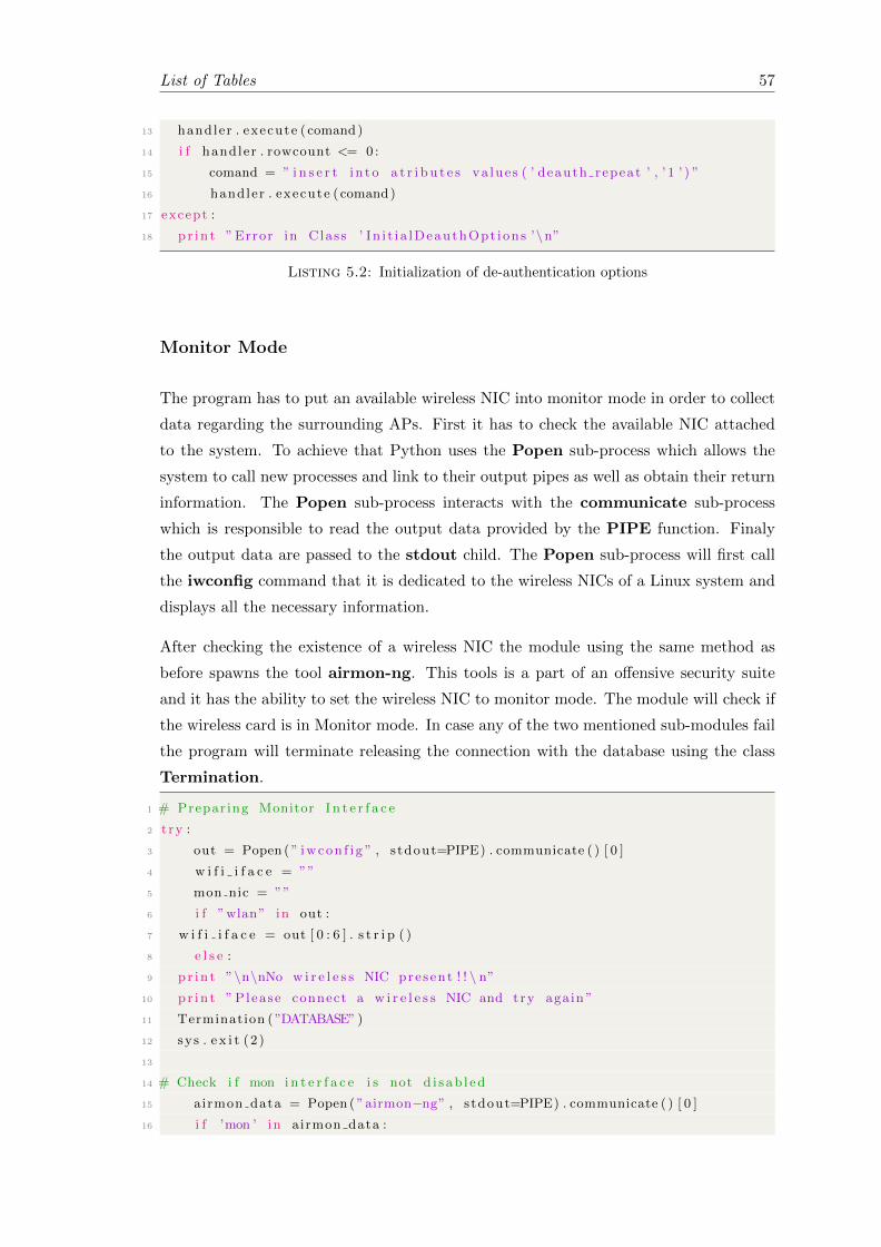
List of Tables 57
13 handler . execute ( comand)
14 i f handler . rowcount <= 0 :
15 comand = ” i n s e r t i n to a t r i bu t e s va lue s ( ’ deauth repeat ’ , ’ 1 ’ ) ”
16 handler . execute ( comand)
17 except :
18 pr in t ”Error in Class ’ In i t i a lDeauthOpt ions ’\n”
Listing 5.2: Initialization of de-authentication options
Monitor Mode
The program has to put an available wireless NIC into monitor mode in order to collect
data regarding the surrounding APs. First it has to check the available NIC attached
to the system. To achieve that Python uses the Popen sub-process which allows the
system to call new processes and link to their output pipes as well as obtain their return
information. The Popen sub-process interacts with the communicate sub-process
which is responsible to read the output data provided by the PIPE function. Finaly
the output data are passed to the stdout child. The Popen sub-process will first call
the iwconfig command that it is dedicated to the wireless NICs of a Linux system and
displays all the necessary information.
After checking the existence of a wireless NIC the module using the same method as
before spawns the tool airmon-ng. This tools is a part of an offensive security suite
and it has the ability to set the wireless NIC to monitor mode. The module will check if
the wireless card is in Monitor mode. In case any of the two mentioned sub-modules fail
the program will terminate releasing the connection with the database using the class
Termination.
1 # Prepar ing Monitor I n t e r f a c e
2 t ry :
3 out = Popen ( ” iwcon f i g ” , s tdout=PIPE) . communicate ( ) [ 0 ]
4 w i f i i f a c e = ””
5 mon nic = ””
6 i f ”wlan” in out :
7 w i f i i f a c e = out [ 0 : 6 ] . s t r i p ( )
8 e l s e :
9 pr in t ”\n\nNo w i r e l e s s NIC present ! ! \ n”10 pr in t ” Please connect a w i r e l e s s NIC and try again ”
11 Termination ( ”DATABASE” )
12 sys . e x i t (2 )
13
14 # Check i f mon i n t e r f a c e i s not d i s ab l ed
15 airmon data = Popen ( ”airmon−ng” , stdout=PIPE) . communicate ( ) [ 0 ]
16 i f ’mon ’ in airmon data :

List of Tables 58
17 pr in t ”\n\nMonitor mode on w i r e l e s s NIC detec ted . ”
18 pr in t ” Please deac t i va t e monitor mode on w i r e l e s s NIC and try again \n”19 Termination ( ”DATABASE” )
20 sys . e x i t (2 )
21 except :
22 pr in t ”Error in Prepar ing Monitor I n t e r f a c e \n”
Listing 5.3: Initialization of de-authentication options
With the successful completion of the previous sub-modules the module will initiate the
creation of Monitor mode to the Wireless NIC. The submodule activates and deactivates
the wireless NIC using the os.system module to call the ifconfig command. After
this ste the wireless NIC enters monitor mode using the airmon tool and the results
are passed to the moninface child. Using this child the autput is striped from the
unnecessary characters to obtain the name of the monito interface.
Finally the module performs a check for some possible applications that might disrupt
the system an terminates them using the os.system module.
1 # Creat ing Monitor I n t e r f a c e
2 t ry :
3
4 # Shut dwon and r e a c t i v a t e w i r e l e s s NIC
5 pr in t ” Se t t i ng up w i r e l e s s NIC : ” + w i f i i f a c e + ”\n”6 os . system ( ’ i f c o n f i g ’ + w i f i i f a c e + ’ down ’ )
7 os . system ( ’ i f c o n f i g ’ + w i f i i f a c e + ’ up ’ )
8
9 pr in t ”Active w i r e l e s s NIC : ” + w i f i i f a c e + ”\n”10
11 # Enable Monitor mode
12 pr in t ’ Enabling Monitor mode ’
13 w i r e l e s s n i c = Popen ( [ ”airmon−ng” , ” s t a r t ” , w i f i i f a c e ] , s tdout=PIPE) .
communicate ( ) [ 0 ]
14
15 # Deleted the unnecessary cha ra c t e r s from the output
16 i f ’mon ’ in w i r e l e s s n i c :
17 pr in t w i r e l e s s n i c [−33:−1] . s t r i p ( )
18 mon nic = w i r e l e s s n i c [−7:−2] . s t r i p ( ” ) ” )
19
20 # Terminate harmful s e r v i c e s
21 i f ’ NetworkManager ’ in w i r e l e s s n i c :
22 pr in t ”\n Terminating ’NetworkManager ’ ”
23 os . system ( ” s e r v i c e network−manager stop ” )
24 i f ’ wpa suppl icant ’ in w i r e l e s s n i c :
25 pr in t ”\n Terminating ’ wpa suppl icant ’ ”
26 os . system ( ” p k i l l wpa suppl icant ” )
27 except :

List of Tables 59
28 pr in t ”Error in Creat ing Monitor I n t e r f a c e \n”
Listing 5.4: Creation of Monitor interface
Scan and Data collection
By the time the wireless NIC is in Monitor mode the module is ready to initiate a scan.
The tool used to scan for nearby APs is the airodump-ng, but because this has by
default some save files the sub-module removes them. The the tool is initiated with
the Popen mentioned before and temporarily saves the scan results in a csv file. The
outcome of the process is passed to an airodump child.
Finishing the scan then the module create an empty dictionary resultAPs where the
scanned results will be stored. In order to filter the results the Scapy programme has
been used by the system. Scapy is a packet manipulation programme that some of its
modules allows the user to capture, forge and extract information from network frames,
wired or wireless. A very important module of this program is the sniff module which
allows the program to extract the values to perform the necessary filtering.
1 # Remove the o ld output from airodump
2 t ry :
3 os . system ( ’rm out . csv −01.∗ ’ )4 except :
5 pr in t ”Error d e l e t i n g Airodump csv f i l e \n”6
7 # Scanning f o r a v a i l a b l e SSIDs
8 pr in t ”SCANNING FOR ACTIVE Wi−Fi NETWORKS”
9 pr in t ”\n\n”10 t ry :
11
12 #Scan and save r e s u l t s
13 airodump = Popen ( [ ”airodump−ng” , ”−−output−format ” , ” csv ” , ”−w” , ”out .
csv ” , mon nic ] )
14
15 resultAPs = {}16
17 #Sn i f f va lue s from scanned data
18 s n i f f ( i f a c e=mon nic , prn=ap di scovery , count=20, s t o r e=False , l f i l t e r=
lambda p : (Dot11Beacon in p or Dot11ProbeResp in p) )
19
20 airodump . terminate ( )
21 db connect ion . commit ( )
22 except :
23 pr in t ”Error in a v a i l a b l e SSIDs\n”

List of Tables 60
Listing 5.5: Scan and Data collection and Filtering
The parameters of the sniff module are:
1. iface: In this field the monitor interface is stored
2. prn: In this field the outcome of the ap-discovery class are stored
3. count: how many results the sniff module to handle
4. store: if the results are to be permanently stored
5. lfilter: perform filtering and pass the results according to settings
In order to indicate to Scapy which network frames the system needs the functions
of Dot11Beacon and Dot11ProbeResp have been used. The functions indicates to
Scapy that it is required to keep these frames only and discard the rest of the. These
frames are the beacons and the Probe requests send by the APs, thus they contain all the
necessary information and the are passed to the p child. The filter operation is handled
by a lamda Python function. These functions have the ability to be anonymous, thus
the are not obliged to be bounded to a name.
Data Filtering
With the completion of the scan process the results have to be filtered in order to obtain
the needed information regarding the APs. The class ap-discovery is called in and
again the Scapy programme is used to perform the task. The BSSID of an AP can be
found in the third address of the captured frames and the result is passed to the bssid
child. The SSID is ectracted by Scapy by using the Dot11Elt function and then is
stored to the resultAPs dictionary.
1
2 # Pars ing Scapy parameters
3 de f ap d i s cove ry ( packet ) :
4 t ry :
5
6 # Search the frame ’ s th i rd address to f i nd the BSSID
7 bs s id = packet [ Dot11 ] . addr3
8 i f b s s i d in resultAPs :
9 re turn
10 p = packet [ Dot11Elt ]
11 cap = packet . s p r i n t f ( ”{Dot11Beacon:%Dot11Beacon . cap%}”

List of Tables 61
12 ”{Dot11ProbeResp:%Dot11ProbeResp . cap%}” ) . s p l i t ( ’+ ’ )
13
14 s s i d = None
15
16 # Search the frame to f i nd the SSID
17 whi le i s i n s t a n c e (p , Dot11Elt ) :
18 i f p . ID == 0 :
19 s s i d = p . i n f o
20 p = p . payload
21
22 # Store the SSID
23 resultAPs [ b s s i d ] = ( s s i d )
24 except :
25 pr in t ”Error in Class ’ ap d i s cove ry ’\n”
Listing 5.6: BSSID and SSID Discovery submodule
After the retrieval of the SSIDs and the BSSIDs from the beacon frames the module
initiates the parsing of the csv file in order to store the measured metrics from the scan
to the database. To do this the sub-module uses the open Python function to open the
csv file. After the csv file has been opened the sub module uses the reader function to
read the content and the replace function to replace zeros with null values. This is done
because the MySQL database cannot read the format the zeros are inputted in. Finally
the sub-module after it checks the rows and places them in order, saves the metrics to
the database and the it closes the csv file, proceeding to the next sub-module.
1
2 # Pars ing the airodump−ng output
3 de f CsvParse ( ) :
4 t ry :
5
6 # Opens the csv output f i l e from airodump−ng7 f = open ( ’ out . csv −01. csv ’ , ’ rb ’ )
8 t ry :
9
10 # Reader ob j e c t i s c r ea ted and ze ro s are r ep laced with ” nu l l ”
11 reader = csv . reader ( x . r ep l a c e ( ’ \0 ’ , ’ ’ ) f o r x in f )
12
13 # The rows o f the f i l e are checked again and placed in order
14 f o r row in reader :
15 i f ’BSSID ’ in row :
16 cont inue
17 i f ’ S ta t i on MAC’ in row :
18 break
19 i f l en ( row ) < 1 :
20 cont inue
21 # The parsed r e s u l t s are s to r ed in to the database
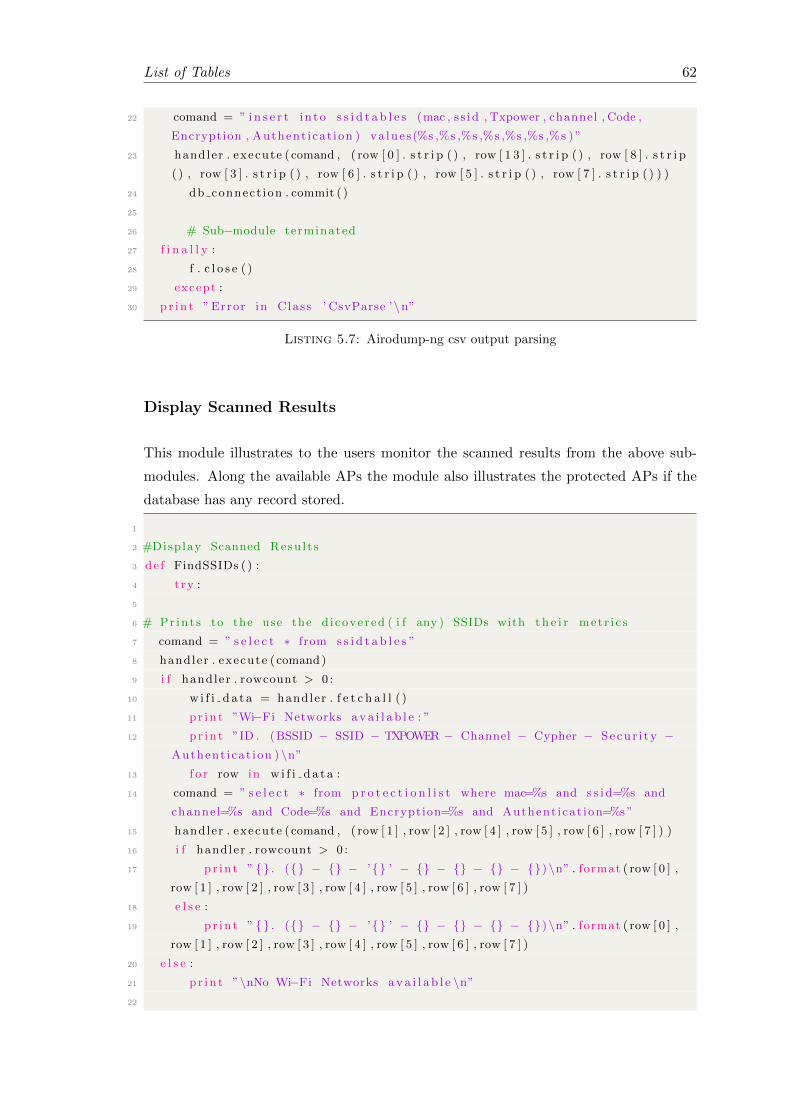
List of Tables 62
22 comand = ” i n s e r t i n to s s i d t a b l e s (mac , s s id , Txpower , channel , Code ,
Encryption , Authent icat ion ) va lue s(%s ,%s ,%s ,%s ,%s ,%s ,%s ) ”
23 handler . execute ( comand , ( row [ 0 ] . s t r i p ( ) , row [ 1 3 ] . s t r i p ( ) , row [ 8 ] . s t r i p
( ) , row [ 3 ] . s t r i p ( ) , row [ 6 ] . s t r i p ( ) , row [ 5 ] . s t r i p ( ) , row [ 7 ] . s t r i p ( ) ) )
24 db connect ion . commit ( )
25
26 # Sub−module terminated
27 f i n a l l y :
28 f . c l o s e ( )
29 except :
30 pr in t ”Error in Class ’ CsvParse ’\n”
Listing 5.7: Airodump-ng csv output parsing
Display Scanned Results
This module illustrates to the users monitor the scanned results from the above sub-
modules. Along the available APs the module also illustrates the protected APs if the
database has any record stored.
1
2 #Display Scanned Resu l t s
3 de f FindSSIDs ( ) :
4 t ry :
5
6 # Pr int s to the use the d icovered ( i f any ) SSIDs with t h e i r met r i c s
7 comand = ” s e l e c t ∗ from s s i d t a b l e s ”
8 handler . execute ( comand)
9 i f handler . rowcount > 0 :
10 w i f i d a t a = handler . f e t c h a l l ( )
11 pr in t ”Wi−Fi Networks a v a i l a b l e : ”
12 pr in t ”ID . (BSSID − SSID − TXPOWER − Channel − Cypher − Secur i ty −Authent icat ion ) \n”
13 f o r row in w i f i d a t a :
14 comand = ” s e l e c t ∗ from p r o t e c t i o n l i s t where mac=%s and s s i d=%s and
channel=%s and Code=%s and Encryption=%s and Authent i cat ion=%s”
15 handler . execute ( comand , ( row [ 1 ] , row [ 2 ] , row [ 4 ] , row [ 5 ] , row [ 6 ] , row [ 7 ] ) )
16 i f handler . rowcount > 0 :
17 pr in t ” {} . ({} − {} − ’{} ’ − {} − {} − {} − {}) \n” . format ( row [ 0 ] ,
row [ 1 ] , row [ 2 ] , row [ 3 ] , row [ 4 ] , row [ 5 ] , row [ 6 ] , row [ 7 ] )
18 e l s e :
19 pr in t ” {} . ({} − {} − ’{} ’ − {} − {} − {} − {}) \n” . format ( row [ 0 ] ,
row [ 1 ] , row [ 2 ] , row [ 3 ] , row [ 4 ] , row [ 5 ] , row [ 6 ] , row [ 7 ] )
20 e l s e :
21 pr in t ”\nNo Wi−Fi Networks a v a i l a b l e \n”22
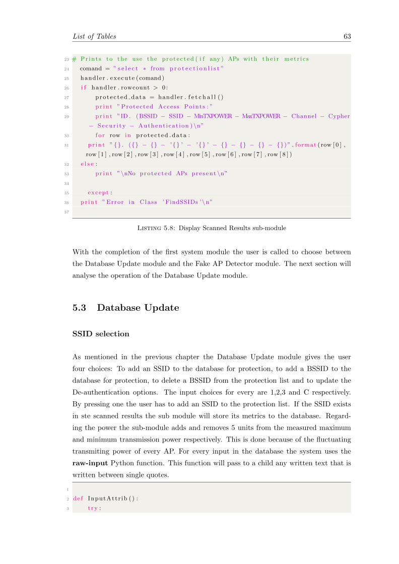
List of Tables 63
23 # Pr int s to the use the protec ted ( i f any ) APs with t h e i r met r i c s
24 comand = ” s e l e c t ∗ from p r o t e c t i o n l i s t ”
25 handler . execute ( comand)
26 i f handler . rowcount > 0 :
27 pro tec t ed data = handler . f e t c h a l l ( )
28 pr in t ”Protected Access Points : ”
29 pr in t ”ID . (BSSID − SSID − MinTXPOWER − MaxTXPOWER − Channel − Cypher
− Secur i ty − Authent icat ion ) \n”30 f o r row in pro tec t ed data :
31 pr in t ” {} . ({} − {} − ’{} ’ − ’{} ’ − {} − {} − {} − {}) ” . format ( row [ 0 ] ,
row [ 1 ] , row [ 2 ] , row [ 3 ] , row [ 4 ] , row [ 5 ] , row [ 6 ] , row [ 7 ] , row [ 8 ] )
32 e l s e :
33 pr in t ”\nNo protec t ed APs pre sent \n”34
35 except :
36 pr in t ”Error in Class ’ FindSSIDs ’\n”37
Listing 5.8: Display Scanned Results sub-module
With the completion of the first system module the user is called to choose between
the Database Update module and the Fake AP Detector module. The next section will
analyse the operation of the Database Update module.
5.3 Database Update
SSID selection
As mentioned in the previous chapter the Database Update module gives the user
four choices: To add an SSID to the database for protection, to add a BSSID to the
database for protection, to delete a BSSID from the protection list and to update the
De-authentication options. The input choices for every are 1,2,3 and C respectively.
By pressing one the user has to add an SSID to the protection list. If the SSID exists
in ste scanned results the sub module will store its metrics to the database. Regard-
ing the power the sub-module adds and removes 5 units from the measured maximum
and minimum transmission power respectively. This is done because of the fluctuating
transmiting power of every AP. For every input in the database the system uses the
raw-input Python function. This function will pass to a child any written text that is
written between single quotes.
1
2 de f InputAttr ib ( ) :
3 t ry :

List of Tables 64
4 whi le True :
5 FindSSIDs ( )
6
7 Choices ( )
8
9 cho i c e = raw input ( ’ Enter the number f o r your cho i c e : ’ )
10 i f cho i c e == ”1” :
11 SSID = raw input ( ’ Enter SSID f o r p ro t e c t i on : ’ )
12 comand = ” s e l e c t ∗ from s s i d t a b l e s where s s i d=%s”
13 handler . execute ( comand , (SSID) )
14 i f handler . rowcount > 0 :
15 comand = ” de l e t e from p r o t e c t i o n l i s t where s s i d=%s”
16 handler . execute ( comand , (SSID) )
17 comand = ” i n s e r t i n to p r o t e c t i o n l i s t (mac , s s id , min Txpower ,
max Txpower , channel , Code , Encryption , Authent icat ion ) s e l e c t mac , s s id ,
Txpower−10,Txpower+10, channel , Code , Encryption , Authent i cat ion \18 from s s i d t a b l e s where s s i d = %s”
19 handler . execute ( comand , (SSID) )
20 db connect ion . commit ( )
21 pr in t ”The AP with the SSID are protec ted ! ”
22 time . s l e e p (1 )
23 e l s e :
24 pr in t ”No such SSID in the v i c i n i t y ”
Listing 5.9: SSID selection sub-module
BSSID selection
Like the SSID selection sub-module the BSSID selection sub-module performs the same
action based on the BSSID instead on the SSID. Again the sub-module adds and removes
5 units from the measured maximum and minimum transmission power respectively.
1 e l i f cho i c e == ”2” :
2 new bss id = raw input ( ’ Enter BSSID f o r p ro t e c t i on : ’ )
3 comand = ” s e l e c t ∗ from s s i d t a b l e s where mac=%s”
4 handler . execute ( comand , ( new bss id ) )
5 i f handler . rowcount > 0 :
6 comand = ” de l e t e from p r o t e c t i o n l i s t where mac=%s”
7 handler . execute ( comand , ( new bss id ) )
8 comand = ” i n s e r t i n to p r o t e c t i o n l i s t (mac , s s id , min Txpower ,
max Txpower , channel , Code , Encryption , Authent icat ion ) s e l e c t mac , s s id ,
Txpower−10,Txpower+10, channel , Code , Encryption , Authent i cat ion \9 from s s i d t a b l e s where mac = %s”
10 handler . execute ( comand , ( new bss id ) )
11 db connect ion . commit ( )
12 pr in t ”The BSSID i s protec ted ”
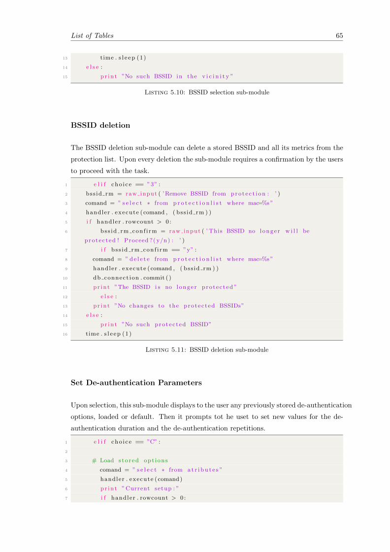
List of Tables 65
13 time . s l e e p (1 )
14 e l s e :
15 pr in t ”No such BSSID in the v i c i n i t y ”
Listing 5.10: BSSID selection sub-module
BSSID deletion
The BSSID deletion sub-module can delete a stored BSSID and all its metrics from the
protection list. Upon every deletion the sub-module requires a confirmation by the users
to proceed with the task.
1 e l i f cho i c e == ”3” :
2 bss id rm = raw input ( ’Remove BSSID from pro t e c t i on : ’ )
3 comand = ” s e l e c t ∗ from p r o t e c t i o n l i s t where mac=%s”
4 handler . execute ( comand , ( bss id rm ) )
5 i f handler . rowcount > 0 :
6 bss id rm con f i rm = raw input ( ’ This BSSID no longe r w i l l be
protec ted ! Proceed ?( y/n) : ’ )
7 i f b s s id rm con f i rm == ”y” :
8 comand = ” de l e t e from p r o t e c t i o n l i s t where mac=%s”
9 handler . execute ( comand , ( bss id rm ) )
10 db connect ion . commit ( )
11 pr in t ”The BSSID i s no l onge r pro tec ted ”
12 e l s e :
13 pr in t ”No changes to the protec ted BSSIDs”
14 e l s e :
15 pr in t ”No such protec ted BSSID”
16 time . s l e e p (1 )
Listing 5.11: BSSID deletion sub-module
Set De-authentication Parameters
Upon selection, this sub-module displays to the user any previously stored de-authentication
options, loaded or default. Then it prompts tot he uset to set new values for the de-
authentication duration and the de-authentication repetitions.
1 e l i f cho i c e == ”C” :
2
3 # Load s to r ed opt ions
4 comand = ” s e l e c t ∗ from a t r i bu t e s ”
5 handler . execute ( comand)
6 pr in t ”Current setup : ”
7 i f handler . rowcount > 0 :
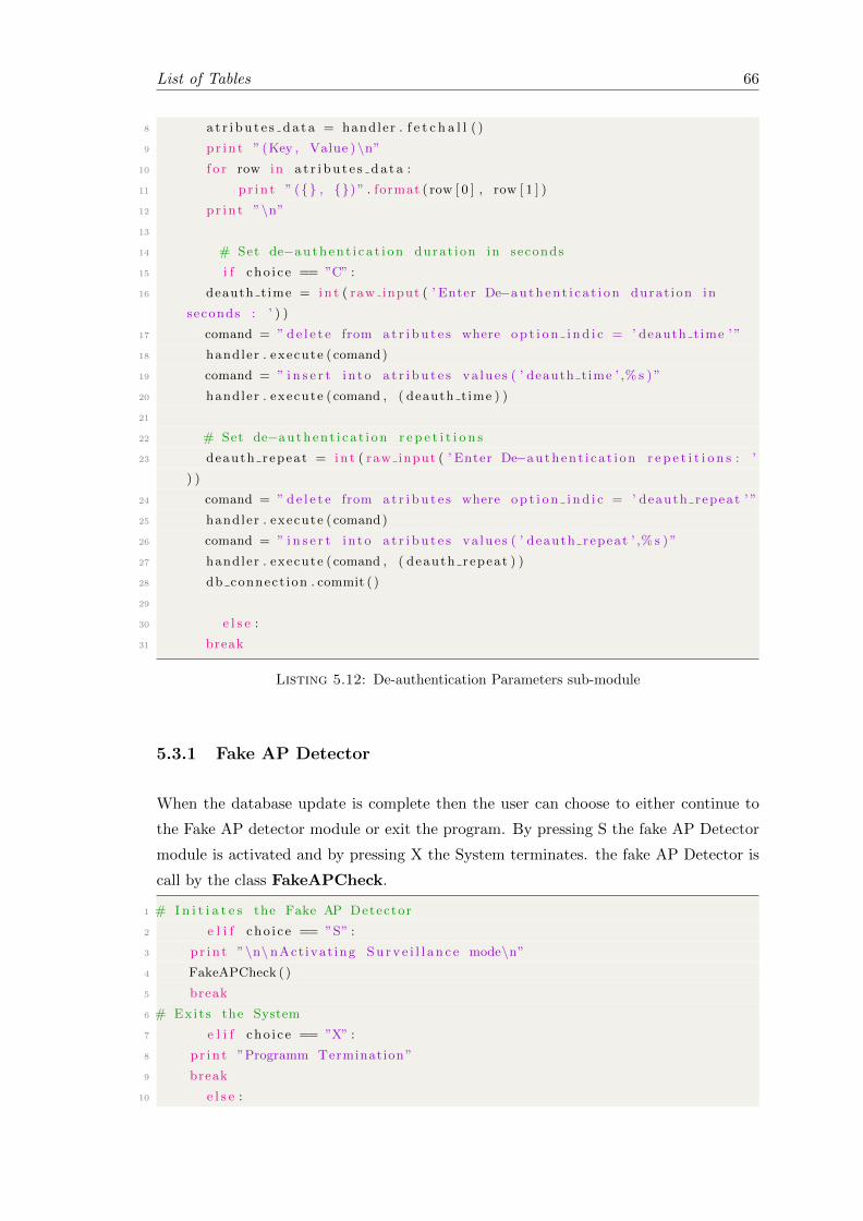
List of Tables 66
8 a t r i bu t e s da t a = handler . f e t c h a l l ( )
9 pr in t ” (Key , Value ) \n”10 f o r row in a t r i bu t e s da t a :
11 pr in t ” ({} , {}) ” . format ( row [ 0 ] , row [ 1 ] )
12 pr in t ”\n”13
14 # Set de−authen t i c a t i on durat ion in seconds
15 i f cho i c e == ”C” :
16 deauth time = in t ( raw input ( ’ Enter De−authen t i c a t i on durat ion in
seconds : ’ ) )
17 comand = ” de l e t e from a t r i bu t e s where op t i o n i nd i c = ’ deauth time ’ ”
18 handler . execute ( comand)
19 comand = ” i n s e r t i n to a t r i bu t e s va lue s ( ’ deauth time ’ ,% s ) ”
20 handler . execute ( comand , ( deauth time ) )
21
22 # Set de−authen t i c a t i on r e p e t i t i o n s
23 deauth repeat = in t ( raw input ( ’ Enter De−authen t i c a t i on r e p e t i t i o n s : ’
) )
24 comand = ” de l e t e from a t r i bu t e s where op t i o n i nd i c = ’ deauth repeat ’ ”
25 handler . execute ( comand)
26 comand = ” i n s e r t i n to a t r i bu t e s va lue s ( ’ deauth repeat ’ ,% s ) ”
27 handler . execute ( comand , ( deauth repeat ) )
28 db connect ion . commit ( )
29
30 e l s e :
31 break
Listing 5.12: De-authentication Parameters sub-module
5.3.1 Fake AP Detector
When the database update is complete then the user can choose to either continue to
the Fake AP detector module or exit the program. By pressing S the fake AP Detector
module is activated and by pressing X the System terminates. the fake AP Detector is
call by the class FakeAPCheck.
1 # I n i t i a t e s the Fake AP Detector
2 e l i f cho i c e == ”S” :
3 pr in t ”\n\ nAct ivat ing Su r v e i l l a n c e mode\n”4 FakeAPCheck ( )
5 break
6 # Exits the System
7 e l i f cho i c e == ”X” :
8 pr in t ”Programm Termination”
9 break
10 e l s e :

List of Tables 67
11 pr in t ” Inva l i d S e l e c t i o n ”
12 except :
13 pr in t ”Error in Class ’ InputAttr ib ’\n”
Listing 5.13: Fake AP Detector and Exit options
Scanned with Stored data comparison
The Fake AP Detector module is activated either after the completion of the Data
collection module or after the Database update module. The module sets two values
as False, the FakeMacAddress and the FakeAPCharacteristics values and then
performs a check to see if there are any SSIDs in the ssidtable. With SSIDs present
in the list then the module firstly check if these SSIDs match the SSIDs stored in in
the protection list and the BSSID is different. If both arguments are true then the
state of the FakeMacAddress variable changes from False to True and the programme
activates the de-uthentication mechanism.
In case both the SSID and the BSSID are the same the it performs a second check
where it compares the channel stored in the database with the scan results. If the
channel differs then the state of the FakeAPCharacteristics becomes True from false
and the module initiates the de-authentication mechanism.
1
2 # Check f o r Fake APs
3 de f FakeAPCheck ( ) :
4 FakeMacAddress = False
5 FakeAPCharacter i s t ics = False
6 t ry :
7 # Preforms a check to i d e n t i f y i f the re are any SSIDs s to r ed in the data
base
8 comand = ” s e l e c t ∗ from s s i d t a b l e s where s s i d in ( s e l e c t s s i d from
p r o t e c t i o n l i s t ) ”
9 handler . execute ( comand)
10 i f handler . rowcount > 0 :
11
12 # Preforms a check to i d e n t i f y i f the re are any APs with same SSID and
d i f f e r e n t BSSID
13 comand = ” s e l e c t ∗ from s s i d t a b l e s as s where s . s s i d in ( s e l e c t s s i d
from p r o t e c t i o n l i s t ) and s .mac not in ( s e l e c t w.mac from p r o t e c t i o n l i s t
as w where s . s s i d = w. s s i d ) ”
14 handler . execute ( comand)
15 i f handler . rowcount > 0 :
16 Fake data = handler . f e t c h a l l ( )
17 FakeMacAddress = True

List of Tables 68
18
19 # Preforms a check to i d e n t i f y i f the re are any APs with same SSID and
BSSID but d i f f e r e n t met r i c s
20 comand = ” s e l e c t d i s t i n c t ∗ from s s i d t a b l e s as s inner j o i n
p r o t e c t i o n l i s t as w on s . s s i d = w. s s i d and s .mac = w.mac where s .
channel != w. channel \21 or s . Code != w. Code or s . Encryption != w. Encryption or s .
Authent i cat ion != w. Authent i cat ion ”
22 handler . execute ( comand)
23 i f handler . rowcount > 0 :
24 a t t r i b da t a = handler . f e t c h a l l ( )
25 FakeAPCharacter i s t ics = True
Listing 5.14: Comparison Scanned with Stored data
Deuthentication mechanism
Depending on which of the two values, the FakeMacAddress and the FakeAPChar-
acteristics, are true the corresponding attack is initialised. The module loads the
options stored in the database regarding the de-authentication attack and the initialises
the Deauth class. In both cases the module operates the same was. In Listing 5.15 is
illustrated the attack based on the detection based on different BSSIDs.
1
2 # I l l u s t r a t e s the r e s u l t s f o r Fake AP with d i f f e r e n t BSSID
3 i f FakeMacAddress :
4 pr in t ”ALERT! ! Fake AP with d i f f e r e n t MAC Found\n”5 a l e r t = ”ALERT! ! Fake AP with d i f f e r e n t MAC Found\n”6 a l e r t = a l e r t + ” (BSSID − SSID − TXPOWER − Channel − Cypher − Secur i ty
− Authent icat ion ) \n”7 pr in t ” (BSSID − SSID − TXPOWER − Channel − Cypher − Secur i ty −
Authent icat ion ) ”
8
9 # The de−authen t i c a t i on mechanism loads the parameters
10 comand = ” s e l e c t op t i o n va r i a b l e from a t r i bu t e s where op t i o n i nd i c = ’
deauth time ’ ”
11 handler . execute ( comand)
12 i f handler . rowcount > 0 :
13 row = handler . f e t chone ( )
14 deauth time = in t ( row [ 0 ] )
15 pr in t ”Deauth time : {}” . format ( deauth time )
16 i f i n t ( deauth time ) > 0 :
17 pr in t ”De−authen t i c a t i ng Fake AP”
18 comand = ” s e l e c t op t i o n va r i a b l e from a t r i bu t e s where op t i o n i nd i c =
’ deauth repeat ’ ”
19 handler . execute ( comand)

List of Tables 69
20 i f handler . rowcount > 0 :
21 raw value = handler . f e t chone ( )
22 deauth repeat = in t ( raw value [ 0 ] )
23 i f deauth repeat <= 0 :
24 deauth repeat = 1
25
26 # The de−authen t i c a t i on mechanism beg ins
27 f o r i in range ( deauth repeat ) :
28 i f l en ( Fake data ) == 1 :
29 f o r row in Fake data :
30 Deauth ( row [ 1 ] , row [ 2 ] , s t r ( row [ 4 ] ) , deauth time ∗ deauth repeat )
31 break
32 e l s e :
33 f o r row in Fake data :
34 Deauth ( row [ 1 ] , row [ 2 ] , s t r ( row [ 4 ] ) , deauth time )
35 pr in t ”\nDe−authen t i c a t i on stoped ”
36 pr in t ”\n\n”37 e l s e :
38 pr in t ”De−authen t i c a t i on mechanism d i s ab l ed \n”
Listing 5.15: Fake AP with different BSSID de-authentication
In Listing 5.15 is illustrated the attack based on the detection with same SSID and
BSSID. The attack is conducted based on the other measured metrics
1
2 # I l l u s t r a t e s the r e s u l t s f o r Fake AP with same BSSID and SSID
3 e l i f FakeAPCharacter i s t ics :
4 pr in t ”ALERT ! ! ! Fake AP with d i f f e r e n t At t r ibute s Found\n”5 a l e r t = ”ALERT ! ! ! Fake AP with d i f f e r e n t At t r ibute s Found\n”6 a l e r t = a l e r t + ” (BSSID − SSID − TXPOWER − Channel − Cypher − Secur i ty
− Authent icat ion ) \n”7 pr in t ” (BSSID − SSID − TXPOWER − Channel − Cypher − Secur i ty −
Authent icat ion ) ”
8
9 # The de−authen t i c a t i on mechanism loads the parameters
10 comand = ” s e l e c t d i s t i n c t ∗ from s s i d t a b l e s as s inner j o i n
p r o t e c t i o n l i s t as w on s . s s i d = w. s s i d and s .mac = w.mac where s .
channel != w. channel ”
11 handler . execute ( comand)
12 i f handler . rowcount > 0 :
13 comand = ” s e l e c t op t i o n va r i a b l e from a t r i bu t e s where op t i o n i nd i c
= ’ deauth time ’ ”
14 handler . execute ( comand)
15 i f handler . rowcount > 0 :
16 row = handler . f e t chone ( )
17 deauth time = in t ( row [ 0 ] )
18 pr in t ”Deauth time : {}” . format ( deauth time )

List of Tables 70
19 i f i n t ( deauth time ) > 0 :
20 pr in t ”De−authen t i c a t i ng Fake AP”
21 comand = ” s e l e c t op t i o n va r i a b l e from a t r i bu t e s where
op t i o n i nd i c = ’ deauth repeat ’ ”
22 handler . execute ( comand)
23 i f handler . rowcount > 0 :
24 raw value = handler . f e t chone ( )
25 deauth repeat = in t ( raw value [ 0 ] )
26 i f deauth repeat <= 0 :
27 deauth repeat = 1
28
29 # The de−authen t i c a t i on mechanism beg ins
30 f o r i in range ( deauth repeat ) :
31 i f l en ( a t t r i b da t a ) == 1 :
32 f o r row in a t t r i b da t a :
33 Deauth ( row [ 1 ] , row [ 2 ] , s t r ( row [ 4 ] ) , deauth time ∗ deauth repeat )
34 break
35 e l s e :
36 f o r row in a t t r i b da t a :
37 Deauth ( row [ 1 ] , row [ 2 ] , s t r ( row [ 4 ] ) , deauth time )
38 pr in t ”\nDe−authen t i c a t i on stoped ”
39 pr in t ”\n\n”40 e l s e :
41 pr in t ”De−authen t i c a t i on mechanism d i s ab l ed \n”42
43 e l s e :
44 pr in t ”No Fake AP found\n”45
46 e l s e :
47 pr in t ” Protec t i on l i s t i s epmty\n”48 except :
49 pr in t ”Error in Class ’FakeAPCheck ’\n”
Listing 5.16: Fake AP with same SSID and BSSID de-authentication
The De-authentication mechanism is called usind the class Deauth. Initially its set
four parameters, Deauthbssid,Deauthssid,Deauthchannel and Deauthtime regarding the
BSSID, SSID, channel and the duration. Using the Popen function described before
the class sets the wireless NIC to monitor mode and configures it to transmit to the
same channel with the Fake AP. When this operation is complete the again using the
Popen function the class initiates the aireplay-ng tool. This tools is a part of an
offensive security sutite and it has the ability to inject forged packets. Based on the
stored de-authentication options the aireplay-ng tool is automatically configured and
it begins the attacks against the Fake AP.
1 # Deauth Attack
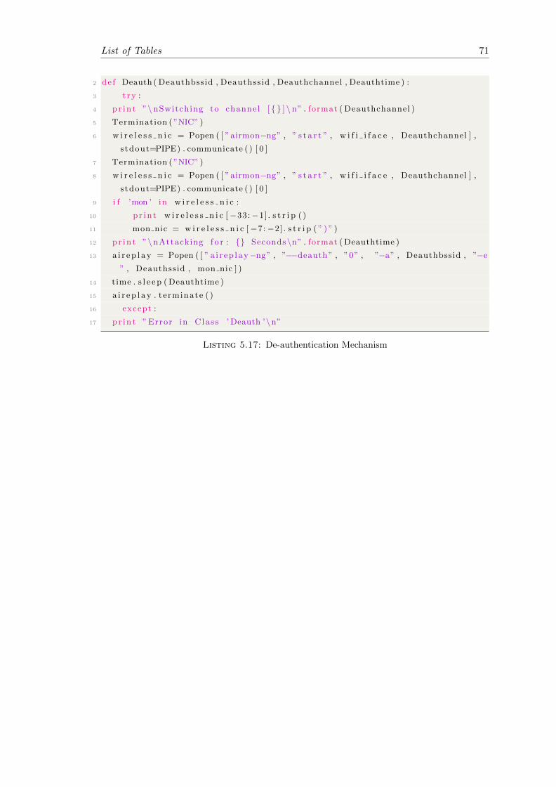
List of Tables 71
2 de f Deauth ( Deauthbssid , Deauthssid , Deauthchannel , Deauthtime ) :
3 t ry :
4 pr in t ”\nSwitching to channel [ { } ] \ n” . format ( Deauthchannel )
5 Termination ( ”NIC” )
6 w i r e l e s s n i c = Popen ( [ ”airmon−ng” , ” s t a r t ” , w i f i i f a c e , Deauthchannel ] ,
s tdout=PIPE) . communicate ( ) [ 0 ]
7 Termination ( ”NIC” )
8 w i r e l e s s n i c = Popen ( [ ”airmon−ng” , ” s t a r t ” , w i f i i f a c e , Deauthchannel ] ,
s tdout=PIPE) . communicate ( ) [ 0 ]
9 i f ’mon ’ in w i r e l e s s n i c :
10 pr in t w i r e l e s s n i c [−33:−1] . s t r i p ( )
11 mon nic = w i r e l e s s n i c [−7:−2] . s t r i p ( ” ) ” )
12 pr in t ”\nAttacking f o r : {} Seconds\n” . format ( Deauthtime )
13 a i r e p l a y = Popen ( [ ” a i r ep l ay−ng” , ”−−deauth” , ”0” , ”−a” , Deauthbssid , ”−e” , Deauthssid , mon nic ] )
14 time . s l e e p ( Deauthtime )
15 a i r e p l a y . terminate ( )
16 except :
17 pr in t ”Error in Class ’Deauth ’\n”
Listing 5.17: De-authentication Mechanism

Chapter 6
Test and Results
6.1 Introduction
This chapter will describe the the chosen approach for the tests performed to evaluate
the effectiveness of the MITM detection and prevention system. The following factors
will have to be taken into account regarding the experiment.
1. The composition of the used equipment to perform the test
2. The procedure that will be followed to perform the test
3. The evaluation of the results
The next sections will provide the explanations to the above factors in the same order.
The test will be conducted based on the requirements that have been analysed in the
previous chapters. The Prevention and detection system must be in position to identify
any fake AP in the are and the successfully attack it in order to prevent any deceived
clients to connect to it.
6.2 Test Setup
The test setup in this experiment will try to emulate a real multi-AP environment,
usually found in public places. It has been decided to cover an area of 90m2 with a
single SSID without any protection in order to make the test as close to real world
scenarios as possible. The place that the experiment will take place is illustrated in
Figure 6.1
72

List of Tables 73
Figure 6.1: Overview of the test set up with all the participants
The test set up consists of five participants, three APs, a fake AP and the detector. All
the APs will have the same SSID using the 802.11g protocol. The operational channel
for all the APs is the channel eleven in the 2.4GHz band. The positions of the APs are
considered to be fixed and they operate with the maximum transmission power available.
Using this set up the whole establishment is covered with the Wi-Fi signal.
The detection System is positioned in the middle of the area inside a room. The system
runs under a Kali Linux distribution so it will be able to operate the wireless NIC in
monitor mode. The system has an external wireless NIC card attached with a detachable
omni directional antenna with 9dbi gain. High gain antennas can improve both the
reception and the transmission of a signal.
Since the fake AP is considered a malicious user it has been decided to be placed in
between the AP1 and the AP2. In a real situation this position would offer the attacker
the advantage to obtain clients from both the APs. Although the fake AP can be mobile,
moving while serving deceived clients can be dangerous because the signal will attenuate
and their connection will be lost. Thus the Fake AP is considered stationary. The fake
AP operates under a Backtrack 5R3 Linux distribution with an external wireless NIC.
Like the detection and prevention system, the antenna is detachable. The fake AP will
use one high gain omni directional antenna with 13dbi gain.
6.3 Test Description
To verify that the detection and prevention system works as expected a number of tests
have to be performed. Initially the System will be tested if it can successfully detect and
add to the protection list the three legitimate APs in the area. All the legitimate APs

List of Tables 74
have different BSSIDs and they are made from different manufacturers. With all the
APs enlisted in the protection list the fake AP will be activated. Four different scenarios
will be tested with the fake AP active:
Scenario 1
In the first scenario the ability of the detection and prevention system to detect and
de-authenticate the fake AP will be tested. The fake AP will be configured to broadcast
with the same SSID as the legitimate APs do. The BSSID of the fake AP will remain
the default one. The wireless NIC of the fake AP will be equipped with the 13dbi high
gain antenna and the channel will be the same as the legitimate APs.
The position of the fake AP is illustrated in the Figure 6.2.
Figure 6.2: Overview of the scenario 1 set up
The expected outcome of the scenario is for the prevention and detection system to
detect the fake AP with the same SSID and start the de-authentication process. This
scenario is considered to be the simplest on because the detection and the prevention
system can easily distinguish the BSSIDs of every AP.

List of Tables 75
Scenario 2
In the second scenario the configuration settings of the fake AP will be changed. Again
it will be configured to transmit with the same SSID as the legitimate APs do but its
BSSID will be changed mimicking the BSSID of the AP1. Some additional changes will
be done to the fake AP. The transmission channel will be set to six instead of eleven,
which is the channel of the legitimate APs operate. Like the first scenario the fake AP
will be equipped with a high gain 13dbi omni directional antenna. The position of the
fake AP will remain the same and it can be seen in the figure 6.3
Figure 6.3: Overview of the scenario 2 set up
The outcome of the second scenario will prove if the detection and prevention system is in
position to successfully detect a fake AP in the first that uses the same SSID and BSSID
with another legitimate AP and later on, to attack it launching the de-authentication
assault. The detection and the prevention mechanisms will rely only on the collected
metrics and especially on the transmission channel and not the BSSID. The detection
of the different channel will prove that the System can rely on the metrics to perform
its task. The channel selection is performed automatically by the wireless NIC when
it is about to connect to the network without the user knowing. From the other hand
setting up the fake AP with an active security mechanism would discourage any clients
to connect to it.

List of Tables 76
Scenario 3
In the third scenario the fake AP will be reconfigured again. In this configuration all
the metrics of the fake AP will be identical to the legitimate ones. The channel will be
set back to eleven and the BSSID of the fake AP will be changed. The new spoofed
BSSID will be the BSSID of th AP2 in the middle of the establishment. Additionally
the fake AP will be relocated behind a wall in order to reduce the transmitting power
received from the System. The hardware set up of the fake AP remains the same having
attached the 13dbi omni directional antenna. The new set up can be seen in the Figure
6.4
Figure 6.4: Overview of the scenario 3 set up
With this configuration the System will try to distinguish which one of the two APs is
the legitimate one based on the received metrics. Having all the attributes mimicked
by the fake AP this is nearly impossible. The only way to distinguish the existence of a
fake AP is by the transmitting power. If the transmitting power of the fake AP is above
the maximum stored transmitted power then there is a high probability that a fake AP
is present

List of Tables 77
6.4 Results
Initially the System, during its first operation before any of the scenarios, scanned
the vicinity for any available APs. The system discovered all three APs that where
meant to be protected by it. As illustrated in the Figure 6.5 the AP1 with BSSID
00:05:59:55:FB:CF, the AP2 with BSSID 00:1F:9F:CF:7B:6D and the AP3 with BSSID
00:1C:A8:0A:98:FF where found in the initial scan and later on they where stored to the
protection list by choosing the SSID which is ”Test Wifi”. Having successfully stored
the legitimate APs the first scenario was introduced.
Figure 6.5: APs discovered and added to the protection list
Scenario 1
During the first scenario the fake AP begun broadcasting with the same SSID as men-
tioned in the test description. The System having the legitimate APs already stored
didn’t require to update the database, so after the initial scan it directly performed a
comparison between the scanned results and the stored APs. In figure Figure 6.6 are
illustrated the scanned results with as well as the stored APs in the protection list. With
green colour are marked the legitimate APs and with red the fake AP which has BSSID
E8:4E:06:0A:02:B0.
Activating the Fake AP Detector module it directly found the fake AP based on the
comparison of the BSSIDs. As it can be seen in Figure 6.7 the System after alerting
the user about the existence of a fake AP in the area it loads the de-authentication
sub-module and sets the wireless NIC to monitor mode.
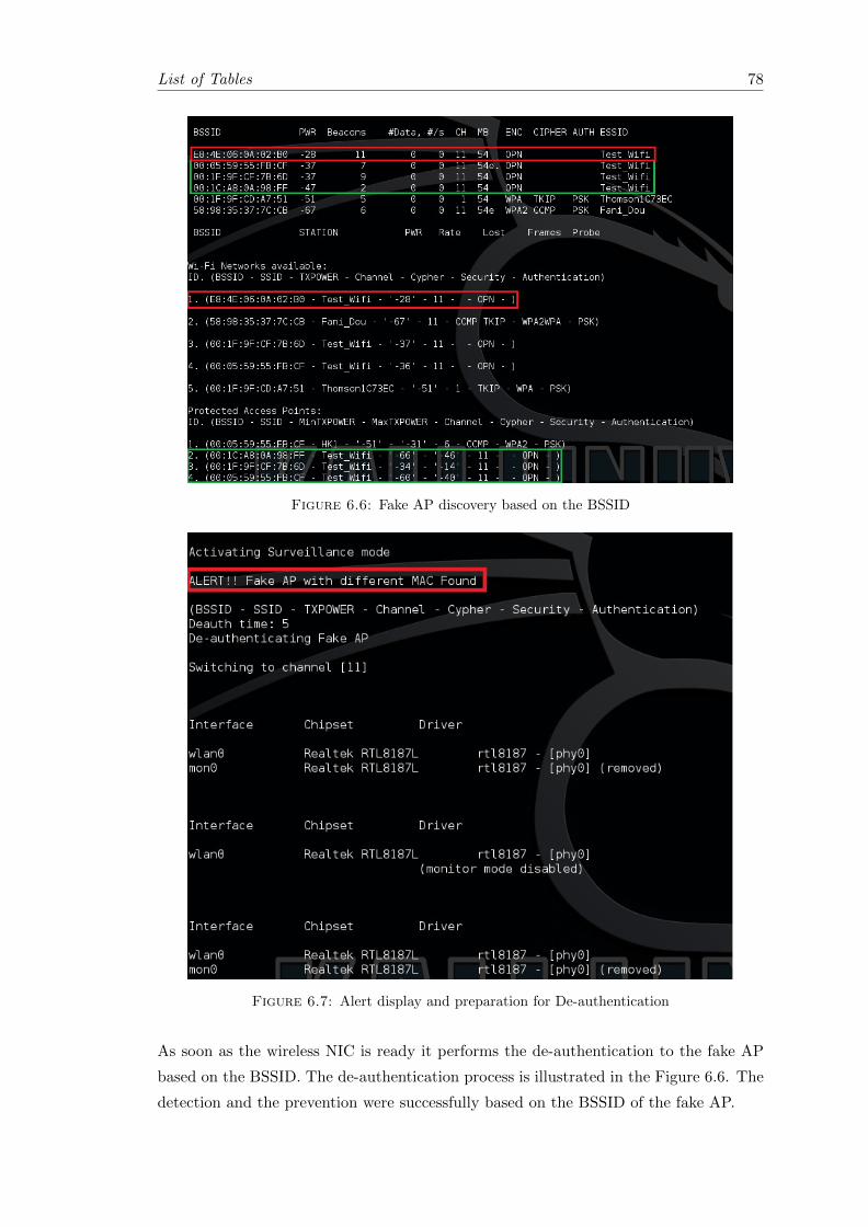
List of Tables 78
Figure 6.6: Fake AP discovery based on the BSSID
Figure 6.7: Alert display and preparation for De-authentication
As soon as the wireless NIC is ready it performs the de-authentication to the fake AP
based on the BSSID. The de-authentication process is illustrated in the Figure 6.6. The
detection and the prevention were successfully based on the BSSID of the fake AP.
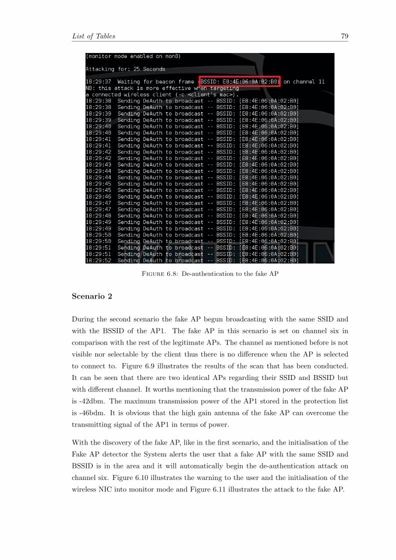
List of Tables 79
Figure 6.8: De-authentication to the fake AP
Scenario 2
During the second scenario the fake AP begun broadcasting with the same SSID and
with the BSSID of the AP1. The fake AP in this scenario is set on channel six in
comparison with the rest of the legitimate APs. The channel as mentioned before is not
visible nor selectable by the client thus there is no difference when the AP is selected
to connect to. Figure 6.9 illustrates the results of the scan that has been conducted.
It can be seen that there are two identical APs regarding their SSID and BSSID but
with different channel. It worths mentioning that the transmission power of the fake AP
is -42dbm. The maximum transmission power of the AP1 stored in the protection list
is -46bdm. It is obvious that the high gain antenna of the fake AP can overcome the
transmitting signal of the AP1 in terms of power.
With the discovery of the fake AP, like in the first scenario, and the initialisation of the
Fake AP detector the System alerts the user that a fake AP with the same SSID and
BSSID is in the area and it will automatically begin the de-authentication attack on
channel six. Figure 6.10 illustrates the warning to the user and the initialisation of the
wireless NIC into monitor mode and Figure 6.11 illustrates the attack to the fake AP.
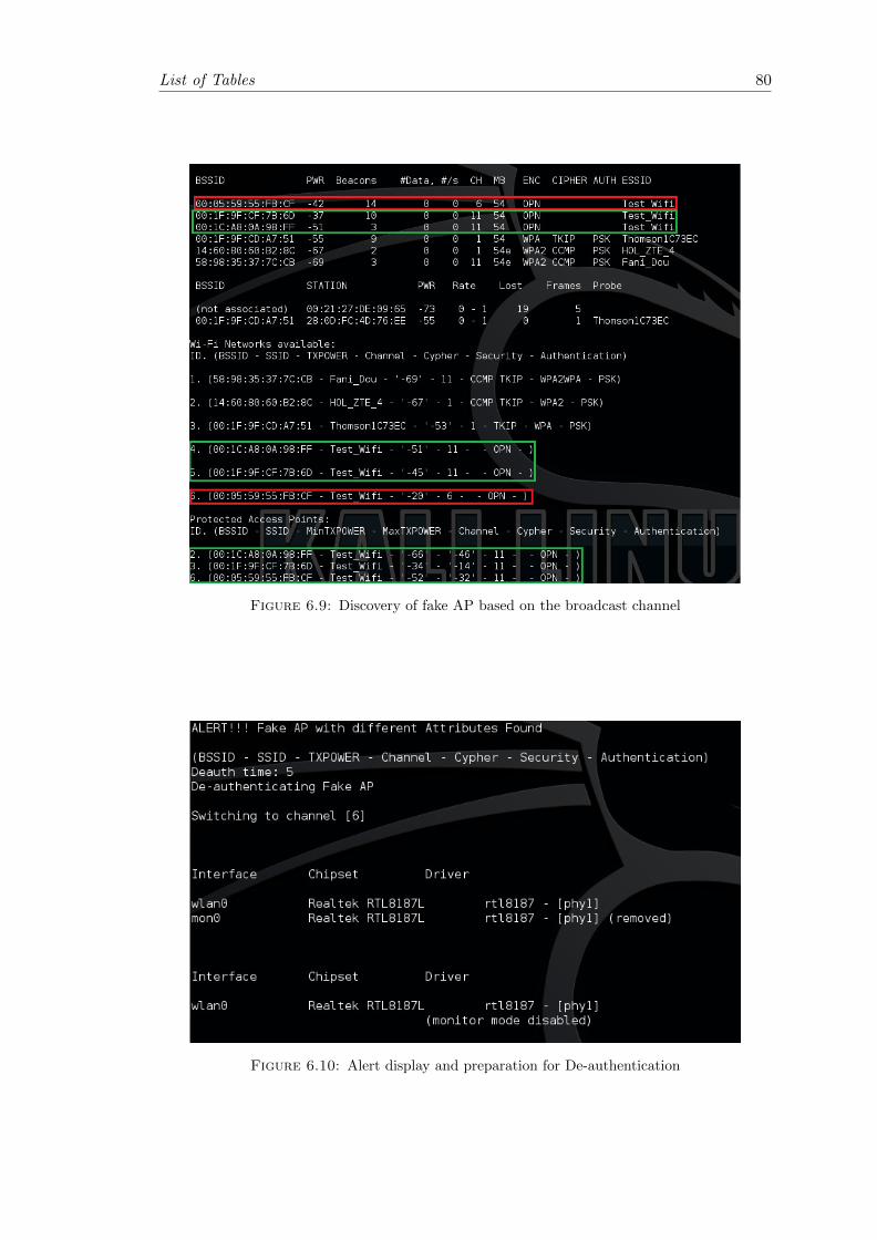
List of Tables 80
Figure 6.9: Discovery of fake AP based on the broadcast channel
Figure 6.10: Alert display and preparation for De-authentication
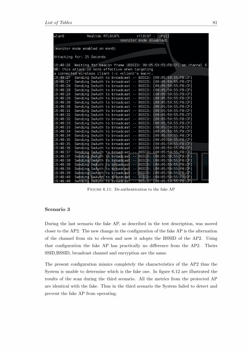
List of Tables 81
Figure 6.11: De-authentication to the fake AP
Scenario 3
During the last scenario the fake AP, as described in the test description, was moved
closer to the AP2. The new change in the configuration of the fake AP is the alternation
of the channel from six to eleven and now it adopts the BSSID of the AP2. Using
that configuration the fake AP has practically no difference from the AP2. Theirs
SSID,BSSID, broadcast channel and encryption are the same.
The present configuration mimics completely the characteristics of the AP2 thus the
System is unable to determine which is the fake one. In figure 6.12 are illustrated the
results of the scan during the third scenario. All the metrics from the protected AP
are identical with the fake. Thus in the third scenario the System failed to detect and
prevent the fake AP from operating.
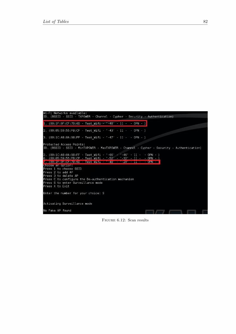
List of Tables 82
Figure 6.12: Scan results
Chapter 7
Conclusion
In this Thesis the problem that was analysed is that a method had to be found in order
to detect and prevent MITM attacks over the 802.11x networks. The problem can be
further expanded to a situation where there is no encryption on the transmitted data
over the Data Link Layer due to the ease of use from the public. This situation is ideal
for a malicious user to intervene and intercept private information from the users. An
attacker can connect to the open wireless network and with the usage of the appropriate
hardware a bridge to the Internet can be created. Thus the attacker can become a
wireless connection provider. The problem was further analysed with the creation of a
private DHCP server routed to an Internet connection. The results from this operation
illustrated that even if the data are encrypted in a higher OSI Layer they can still be
intercepted by the attacker using the right tools. Additionally it was explained how
the attacker can kidnap the clients from the legitimate APs in order to use the unsafe
connection. This combination of problems where approached on the basis that the key
point in the malicious operation is the disruption of the fake AP’s functionality. Without
the ability to deceive the clients, the attacker losses any advantage to gain the users trust
and thus the MITM attack will be in vain.
To achieve such a result a system was created in order to perform the task. The system
based on the legitimate AP points creates a database where the APs metrics and char-
acteristics are stored. Using this database it performs regular scans in order to discover
new APs with characteristics that denote that a MITM attack is going to take place.
Non registered APs with same SSIDs are considered hostile and they are attacked by
the system in order to protect any deceived client from connecting to them. The system
performed the task as long as the fake AP had a different BSSID on was broadcasting in
another channel. Since the fake AP adopted all the characteristics from a legitimate AP
it became impossible to the system to identify it and then attack it. This happens for
83

List of Tables 84
two reasons: because of the flaws on the MAC sub layer and the shared medium. Even
if the system was able to identify the existence of a fake AP in the vicinity attacking it
would cause a friendly attack as well, since they both use same characteristics and there
are no guiding lines in the air. Nevertheless the system was able to detect and prevent
an imminent MITM when the fake AP had a different BSSID or a different channel,
acquiring a 66% of success. The system can be further developed in the detection field
by adding features like detection upon the transmitting power of live monitoring of the
transmitting data This would give the system the ability not only to prevent MITM
attacks based on a fake AP but also identify Dos attacks or other malicious activities in
its vicinity.

Bibliography
[1] author = ”Chibiao Liu, James Yu”, title = ”A Solution to WLAN Authentication and
Association DoS Attacks”, journal = ”IAENG International Journal of Computer
Science, 34:1, IJCS3414”, year = ”2007”
[2] author = ”Le Wang, Alexander M. Wyglinski”, title = ”A Combined Approach for
Distinguishing Different Types of Jamming Attacks Against Wireless Networks”,
year = ”2013”
[3] author = ”Zouheir Trabelsi, Kadhim Hayawi, Arwa Al Braiki, Sujith Samuel
Mathew”,, title = ”Network Attacks and Defenses: A Hands-on Approach”, year
= ”2012”, publisher = ”CRC Press”,
[4] author = ”Colin Knudsen”, title = ”Smartphones, Tablets and the Mobile Revolu-
tion”, url = ”http : //www.coadydiemar.com/html/rbvolume62012.html”,
[5] author = ”Abid Hussain, Nazar A. Saqib, Usman Qamar, Muhammad Zia, and
Hassan Mahmood”, title = ”Protocol-Aware Radio Frequency Jamming in Wi-Fi and
Commercial Wireless Networks”, journal = ”JOURNAL OF COMMUNICATIONS
AND NETWORKS”, year = ”2014”
[6] author = ”Simon S. Lam”, title = ”A Carrier Sense Multiple Access Protocol for
Local Networks”,
[7] author = ”Anna M. Johnston, Peter S. Gemmell”, title = ”Authenticated Key Ex-
change Provably Secure against the Man-in-the-Middle Attack”, year = ”2001”
[8] author = ”Wenyuan Xu, Wade Trappe, Yanyong Zhang”, title = ”Jamming Sensor
Networks: Attack and Defense Strategies”, year = ”2006”
[9] author = ”Wenyuan Xu, Wade Trappe, Yanyong Zhang and Timothy Wood”, ti-
tle = ”The Feasibility of Launching and Detecting Jamming Attacks in Wireless
Networks”, year = ”2016”
85

List of Tables 86
[10] author = ”Simon Eberz, Martin Strohmeier, Matthias Wilhelm, Ivan Martinovic”,
title = ”A Practical Man-In-The-Middle Attack on Signal-Based Key Generation
Protocols”, year = ”2011”
[11] author = ”Konstantinos Pelechrinis, Marios Iliofotou and Srikanth V. Krishna-
murthy”, title = ”Denial of Service A ttacks in Wireless Networks: The Case of
Jammers”, journal = ”IEEE COMMUNICATIONS SURVEYS AND TUTORIALS”,
year = ”2011”
[12] author = ”Seung Yeob Nam, Dongwon Kim, and Jeongeun Kim”, title = ”Enhanced
ARP: Preventing ARP Poisoning-based Man-in-the-Middle Attacks”, year = ”2015”
[13] author = ”Yihong Zhou, Dapeng Wu, Scott M. Nettles”, title = ”Analyzing and
Preventing MAC-Layer Denial of Service Attacks for Stock 802.11 Systems”, year =
”2005”
[14] author = ”Arash Habibi Lashkari, Mir Mohammad Seyed Danesh, Behrang
Samadi”, title = ”A Survey on Wireless Security protocols (WEP, WPA and
WPA2/802.11i)”, year = ”2010”
[15] author = ”Tope Olufon, Carlene E-A Campbell, Stephen Hole, Kapilan Radhakr-
ishnan and Arya Sedigh”, title = ”Mitigating External Threats in Wireless Local
Area Networks”, journal = ”International Journal of Communication Networks and
Information Security (IJCNIS)”, year = ”2014”
[16] author = ”Ken Tang, Mario Gerla”, title = ”MAC LAYER BROADCAST SUP-
PORT IN 802.11 WIRELESS NETWORKS”, year = ”2001”
[17] author = ”Hongqiang Zhai1, Younggoo Kwon and Yuguang Fang”, title = ”Perfor-
mance analysis of IEEE 802.11 MAC protocols in wireless LANs”, year = ”2004”
[18] author = ”Peter Valian and Todd K. Watson”, title = ”NETREG: AN AUTO-
MATED DHCP REGISTRATION SYSTEM”, year = ”2000”
[19] author = ”Benjamin E. Henty”, title = ”A Brief Tutorial on the PHY and MAC
layers of the IEEE 802.11b Standard”, year = ”2001”
[20] author = ”Kalpana Sharma, Mrinal Kanti Ghose”, title = ”Wireless Sensor Net-
works: An Overview on its Security Threats”, year = ”2010”
[21] author = ”Vishnu Navda, Aniruddha Bohra, Samrat Ganguly, Dan Rubenstein”,
title = ”Using Channel Hopping to Increase 802.11 Resilience to Jamming Attacks”,
year = ”2006”

List of Tables 87
[22] author = ”Haidong Xia and Jose Carlos Brustoloni”, title = ”Hardening Web
Browsers Against Man-in-the-Middle and Eavesdropping Attacks”, year = ”2004”
[23] author = ”Mar tin Beck, Erik Tews”, title = ”Practical Attacks Against WEP and
WPA”, year = ”2009”
[24] author = ”Aristides Mpitziopoulos, Damianos Gavalas, Charalampos Konstan-
topoulos and Grammati Pantziou”, title = ”A Survey on Jamming Attacks and
Countermeasures in WSNs”, year = ”2009”
[25] author = ”Moffat Mathews, Ray Hunt”, title = ”VOLUTION OF WIRELESS LAN
SECURITY ARCHITECTURE TO IEEE 802.11i (WPA2)”, year = ”2006”
[26] author = ”Rolf Opplige, Ralf Hauser and David Basin ”, title = ”SSL/T LS Session-
Aware User AuthenticationOr How to Effectively Thwart the Man-in-the-Middle”,
year = ”2005”
[27] author = ”Alejandro Proano, Loukas Lazos”, title = ”Selective Jamming Attacks
in Wireless Networks”, year = ”2010”
[28] author = ”Ali Hamieh, Lynda Mokdad”, title = ”Detection of Radio Interference
Attacks in VANET”, year = ”2010”
[29] author = ”Python (2015). Python documentation”, title = ”Built-in Functions”,
url = ”https : //docs.python.org/2/library/functions.htmlisinstance”,
[30] author = ”Python Tutorials”, title = ”Python String replace() Method”, url =
”http : //www.tutorialspoint.com/python/stringreplace.htm”,
[31] author = ”Python (2015). Python documentation”, title = ”CSV File Reading and
Writing”, url = ”https : //docs.python.org/2/library/csv.html”,
[32] author = ”Python (2015). Python documentation”, title = ”Adding new protocols”,
url = ”http : //www.secdev.org/projects/scapy/doc/builddissect.htmllayers”,
[33] author = ”Python (2015). Python documentation”, title = ”Lexical analysis”, url
= ”https : //docs.python.org/2/reference/lexicalanalysis.html”,
[34] author = ”Python (2015). Python documentation”, title = ”Sniffer 0.3.5”, url =
”https : //pypi.python.org/pypi/sniffer”,
[35] author = ”Python (2015). Python documentation”, title = ”Miscellaneous operat-
ing system interfaces”, url = ”https : //docs.python.org/2/library/os.html”,
[36] author = ”Python (2015). Python documentation”, title = ”Common string oper-
ations”, url = ”https : //docs.python.org/2/library/string.html”,
List of Tables 88
[37] author = ”Python (2015). Python documentation”, title = ”Subprocess manage-
ment”, url = ”https : //docs.python.org/2/library/subprocess.html”,
[38] author = ”Scapy documentation”, title = ”Scapy”, url = ”http :
//www.secdev.org/projects/scapy/”,
[39] author = ”Scapy documentation”, title = ”Usage”, url = ”http :
//www.secdev.org/projects/scapy/doc/usage.html”,
[40] author = ”Aircrack-ng.org”, title = ”Airodump-ng”, url = ”http :
//www.aircrack − ng.org/doku.php?id = airodump− ng”,
[41] author = ”Aircrack-ng.org”, title = ”Airmon-ng”, url = ”http : //www.aircrack−ng.org/doku.php?id = airmon− ng”,
[42] author = ”Aircrack-ng.org”, title = ”Aireplay-ng”, url = ”http : //www.aircrack−ng.org/doku.php?id = aireplay − ng”,
[43] author = ”Aircrack-ng.org”, title = ”Airbase-ng”, url = ”http : //www.aircrack−ng.org/doku.php?id = airbase− ng”,
[44] author = ”Aircrack-ng.org”, title = ”Airdrop-ng”, url = ”http : //www.aircrack−ng.org/doku.php?id = airdrop− ng”,