Detailed Post-Soft Impact Progressive Damage Assessment ... · PDF fileDetailed Post-Soft...
30
Aaron Siddens and Javid Bayandor Virginia Tech, Blacksburg, Virginia Mark Celestina Glenn Research Center, Cleveland, Ohio Detailed Post-Soft Impact Progressive Damage Assessment for Hybrid Structure Jet Engines NASA/TM—2014-218397 December 2014 https://ntrs.nasa.gov/search.jsp?R=20150000885 2018-04-26T19:08:00+00:00Z
Transcript of Detailed Post-Soft Impact Progressive Damage Assessment ... · PDF fileDetailed Post-Soft...
Aaron Siddens and Javid BayandorVirginia Tech, Blacksburg, Virginia
Mark CelestinaGlenn Research Center, Cleveland, Ohio
Detailed Post-Soft Impact Progressive DamageAssessment for Hybrid Structure Jet Engines
NASA/TM—2014-218397
December 2014
https://ntrs.nasa.gov/search.jsp?R=20150000885 2018-04-26T19:08:00+00:00Z
NASA STI Program . . . in Pro le
Since its founding, NASA has been dedicated to the advancement of aeronautics and space science. The NASA Scienti c and Technical Information (STI) program plays a key part in helping NASA maintain this important role.
The NASA STI Program operates under the auspices of the Agency Chief Information Of cer. It collects, organizes, provides for archiving, and disseminates NASA’s STI. The NASA STI program provides access to the NASA Aeronautics and Space Database and its public interface, the NASA Technical Reports Server, thus providing one of the largest collections of aeronautical and space science STI in the world. Results are published in both non-NASA channels and by NASA in the NASA STI Report Series, which includes the following report types: • TECHNICAL PUBLICATION. Reports of
completed research or a major signi cant phase of research that present the results of NASA programs and include extensive data or theoretical analysis. Includes compilations of signi cant scienti c and technical data and information deemed to be of continuing reference value. NASA counterpart of peer-reviewed formal professional papers but has less stringent limitations on manuscript length and extent of graphic presentations.
• TECHNICAL MEMORANDUM. Scienti c
and technical ndings that are preliminary or of specialized interest, e.g., quick release reports, working papers, and bibliographies that contain minimal annotation. Does not contain extensive analysis.
• CONTRACTOR REPORT. Scienti c and
technical ndings by NASA-sponsored contractors and grantees.
• CONFERENCE PUBLICATION. Collected papers from scienti c and technical conferences, symposia, seminars, or other meetings sponsored or cosponsored by NASA.
• SPECIAL PUBLICATION. Scienti c,
technical, or historical information from NASA programs, projects, and missions, often concerned with subjects having substantial public interest.
• TECHNICAL TRANSLATION. English-
language translations of foreign scienti c and technical material pertinent to NASA’s mission.
Specialized services also include organizing and publishing research results, distributing specialized research announcements and feeds, providing information desk and personal search support, and enabling data exchange services.
For more information about the NASA STI program, see the following:
• Access the NASA STI program home page at http://www.sti.nasa.gov
• E-mail your question to [email protected] • Phone the NASA STI Information Desk at 757-864-9658 • Write to:
NASA STI Information DeskMail Stop 148NASA Langley Research CenterHampton, VA 23681-2199
Aaron Siddens and Javid BayandorVirginia Tech, Blacksburg, Virginia
Mark CelestinaGlenn Research Center, Cleveland, Ohio
Detailed Post-Soft Impact Progressive DamageAssessment for Hybrid Structure Jet Engines
NASA/TM—2014-218397
December 2014
National Aeronautics andSpace Administration
Glenn Research CenterCleveland, Ohio 44135
Acknowledgments
The great support provided by the following colleagues at NASA is highly acknowledged and appreciated. Special thanks also go to the research team at CRASH Lab for their technical contribution to the work undertaken, the Department of Mechanical Engineering and, in particular Dr. Kenneth Ball, as well as the College of Engineering at Virginia Tech, without their generous contribution and sel ess support this work could have not been successfully completed. This project has been partially supported through the NGFF Program.
NASA Glenn Research Center (GRC)
Aeropropulsion Division, Dr. D.R. ReddyTurbomachinery and Heat Transfer Branch, Dr. J. Heidmann and Mr. S. KulkarniStructures and Materials Division, Drs. G. Stefko, M. Bakhla, C. Chamis, M. Melis, M. PereiraResearch Directorate, Drs. J.F. Lei, M.D. Kankam and Ms. B. Beznoska Also, Drs. A. Ameri, D. Ashpis, P. Jorgenson, D. Krause, K. Carney, W. To, P. Sockol, J. Verse, and W. Wright
Available from
NASA STI Information DeskMail Stop 148NASA Langley Research CenterHampton, VA 23681-2199
National Technical Information Service5301 Shawnee Road
Alexandria, VA 22312
Available electronically at http://www.sti.nasa.gov
Trade names and trademarks are used in this report for identi cation only. Their usage does not constitute an of cial endorsement, either expressed or implied, by the National Aeronautics and
Space Administration.
Level of Review: This material has been technically reviewed by technical management.
This report is a formal draft or working paper, intended to solicit comments and
ideas from a technical peer group.
This report contains preliminary ndings, subject to revision as analysis proceeds.
Abstract Currently, certification of engine designs for resistance to bird strike is reliant on physical tests. Predictive modeling of engine structural damage has mostly been limited to evaluation of individual forward section components, such as fan blades within a fixed frame of reference, to direct impact with a bird. Such models must be extended to include interactions among engine components under operating conditions to evaluate the full extent of engine damage. This paper presents the results of a study aim to develop a methodology for evaluating bird strike damage in advanced propulsion systems incorporating hybrid composite/metal structures. The initial degradation and failure of individual fan blades struck by a bird were investigated. Subsequent damage to other fan blades and engine components due to resultant violent fan assembly vibrations and fragmentation was further evaluated. Various modeling parameters for the bird and engine components were investigated to determine guidelines for accurately capturing initial damage and progressive failure of engine components. Then, a novel hybrid structure modeling approach was investigated and incorporated into the crashworthiness methodology. Such a tool is invaluable to the process of design, development, and certification of future advanced propulsion systems.
1 Introduction The threat of foreign object impact (FOI), such as bird strike or hail strike, on turbofan engines is a major concern for commercial airlines and engine manufacturers. The FAA has set specific airworthiness standards under Federal Aviation Regulation (FAR) 33.76 requiring that engines be capable of withstanding impact with birds ranging from 0.8 to 8 lbs. without sustaining damage that poses a fatal threat to passengers and crew. To meet these standards, jet engine manufacturers rely heavily on a multitude of costly physical tests requiring the destruction of full-scale engines by simulating bird strikes using birds or bird surrogates in accordance with FAA guidelines.
Bird strike on a turbofan blade can be defined as a complex, transient fluid-solid interaction between the soft bird material and the fan blade [1]. Upon impact, the internal solid structures of the bird are rapidly deteriorated as the resultant shockwave propagates through its body, breaking internal bonds of the bird and transforming its material properties to that of a viscous fluid contained within a shelled control volume. This causes pressure to be built up within the bird material and, as the shockwave progresses, leads to the formation of pressure release waves that force the transient fluidic matter out of the initial control volume enclosure [2]. The bird material expands nonlinearly beyond the initial point of impact, creating a larger contact region and causing greater potential for damage to additional fan blades as well as other engine components outside of the initial impact zone.
Several types of damage occur in the forward fan section of an engine once subjected to an FOI. One type of damage is that resulting from a bird directly impacting several fan blades. Disintegration and degradation of the fan blades can cause decreased engine performance and further damage to other components as fragments or detached blades are ingested into the engine. Another significant source of damage is that resulting from contact between the fan blades and engine casing leading to high tangential friction and normal impact forces along the blade tips and the inside wall of the engine casing. Minute disturbances in the fan assembly position will bring the blades into contact with the casing, producing high blade tip stresses as they shear against sections of the engine casing. Bird impact along the length of a fan blade induces a moment about the engine axel and can remove mass from portions of the fan assembly, shifting the center of mass away from the axis of rotation. This can induce
NASA/TM—2014-218397 1
vibrations that move the fan blades through the small blade tip tolerance. Fragments resulting from blade and casing damage are ingested into downstream sections of the engine and can cause further destruction.
Capturing the deterioration of engine components resulting from violent contact between the fan blade tips and the engine casing is essential for characterizing damage in turbofan engines. This is a particularly challenging task for modern fan blades utilizing composites with reinforcing metal components, with the resulting part called a hybrid structure. Tools for accurately predicting damage in these structures are not well established. New methods are needed to facilitate the design and analysis of future propulsion designs incorporating these advanced structures.
The goal of the current study is to develop a methodology for predicting bird strike damage in jet engine forward fan sections incorporating the true nature of structural dynamics and destructive interactions. Critical features under investigation are the degradation and disintegration of the turbofan blades and the engine casing. Three-dimensional explicit finite element analysis models will be employed to simulate the highly nonlinear, transient response of the forward engine section resulting from impact and capture the associated turbofan blade damage, fan assembly vibrations, and subsequent engine casing damage. A methodology for predicting these damage effects is imperative to facilitating the design and certification processes of future advanced propulsion systems.
2 Problem Approach
A review of the literature shows several approaches employed through previous research programs to predict bird strike damage to jet engine fan assemblies. Several researchers have conducted in-depth studies of damage to an individual fan blade resulting from bird impact to assess the response and damage of the structure [3-5]. In addition, some investigators have studied the effects of impact between a bird and multiple (three or four) blade configurations in accordance with the distributed impact that occurs when a bird strikes several blades as it passes through the front section of the engine [6, 7]. Lastly, there are few models that include the entire fan assembly arranged about a central hub in which the fan blades rotate about a rigid point.
While these models capture the damage that occurs to a blade or blades directly impacted by a bird, they do not incorporate the engine casing or a deformable axel into the simulation and the highly interactive role that their dynamic responses play in sustaining or containing damage. Therefore, these models are unable to capture the post-impact damage responses that may result from abrasion of the fan blade tips onto the engine casing. Also, these studies are often limited to individual cases in which one simulation is developed to match experimental or analytical data without consideration for the effect that modeling changes may impose on predicted results.
The approach chosen for this study was to model the bird impact damage for a jet engine forward section capturing several key features:
Initial impact between the bird and fan blades and the resulting total damage,
Mass unbalancing, leading to fan assembly and main axel vibration and post-impact dynamic damage,
Blade tip shearing against the engine casing and the resulting damage both the blade and the casing.
NASA/TM—2014-218397 2
Additionally, it is aimed to explore modeling approaches that affect the predicted initial and final damage in order to establish general guidelines for bird strike damage assessment on engine forward sections and any possible conclusions contributing to the design or certification procedures.
3 Problem Complexities
The difficulties of modeling bird strike damage on a full fan section are numerous even for a simplified model. In addition to the common challenge of accurately modeling progressive material failure, the following major complexities must also be addressed:
3.1 Bird/Fluid Modeling
An important complexity was modeling the bird accurately using an approach that can capture large deformations and separation of the fluidic bird material following initial impact without incurring heavy element distortions that can lead to mesh entanglement and ultimately divergence of the analysis. To avoid this, a meshless formulation was utilized for the bird. This approach is discussed in detail in section 5.
3.2 Contact Modeling
Essential interactions required to be incorporated into models included bird-blade, bird-casing, blade-casing, blade-blade, and blade-self contact. Contact between the bird and engine components had to accurately capture the interaction forces between the bird and component surfaces over time. Since contact between interacting parts due to material failure in element eliminated areas was lost, contact regions had to be redefined over time as the simulation progressed. FE models had to be able to adequately impose contact between eroding parts as contact interfaces continued to evolve.
In addition, further complexity arose due to the close proximity and high velocity of the blade tips relative to the casing elements. In post impact, blade elements penetrated the casing due to oscillations associated with unbalancing in the fan assembly. Contact models were utilized that detected this penetration and applied subsequent interaction forces to remove the penetration and thus model the contact between elements. However, if the time step was too large, the blade elements penetrated the casing beyond the limits that the contact formulation was capable of detecting and failed to impose the constraint, causing unrealistic penetrations between the parts. To prevent this, the initial time step was lowered until it was observed that excessive element penetration no longer occurred for the range of fan assembly velocities under investigation.
3.3 Fan Unbalancing and Vibrations
Impact between the bird and fan blades at a distance away from the center of the hub moved the fan assembly off center, causing it to oscillate about the engine’s axis of rotation. In addition, if the blades fractured, the center of mass shifted permanently, triggering a strong rattling effect as the fan blade tips hit the casing and caused damage to both the blades and the casing. Suitable models were required to capture damage not only from direct impact, but resulting from post-impact damage to the rest of the structure due to unbalancing and vibrations.
NASA/TM—2014-218397 3
3.4 Pre-stressing
The angular velocity of a jet engine fan section causes centripetal forces along the length of fan blades that pull them toward the center of the hub and maintain the circular path of the fan stage around the axis of rotation. Stresses are greatest at the blade root and decrease along the length of the blade until reaching zero at the tip. In order to accurately predict damage, it was necessary to assess the state of stress and strain in the blades as a result of both the bird impact and the initial state of stress due to centripetal acceleration.
4 Soft Impact Theory
At velocities around and above 50 m/s, a bird impacting an object with a much higher stiffness induces a shockwave that propagates in the direction of relative velocity through its body and breaks its internal bonds. This leads to a multi-stage problem as the bird’s properties, past the shock, change from solid to fluid. The several facets of the impact event can be characterized by the following main stages: (1) solid-structure impact, (2) solid-fluid transition, (3) fluid-structure interaction, (4) nonlinear growth of impact region, and (5) structural damage.
Originally, the bird mass is solid, and the initial impact with a fan blade can be labeled as a “hard” impact in which contact forces are highly localized about a relatively small impact region. The velocity of material over the contact area instantly decreases, and a shock pressure develops in both the projectile and the target as material is compressed. Assuming both objects behave elastically, an expression for the shock pressure, or Hugoniot pressure, P_H, induced in the bird can be derived from:
(1)
where and are the densities of the bird and the blade, respectively, and are the shockwave speed in the bird and blade, and is the relative impact velocity [1]. In the case of bird strike, the following will be valid: , and subsequently the above equation can be simplified to:
(2)
The shock pressure created inside of the bird is greater than its material strength. Therefore, the structural bonds of the bird are broken, and the solid material undergoes a transition to a fluid.
Concentration of the shock pressure along an interface, bound by the speed of sound in the object, produces a shockwave. The shockwave then propagates at a speed much faster than the relative bird/blade velocity, at which the bird material properties are rapidly changed into fluid. Consequently, a large pressure gradient is formed across the boundary of the surrounding air and the control volume containing the bird. Pressure release waves force the fluidic matter away from the bird center, while the shock pressure decays to a lower steady pressure [1]. This steady pressure, , is defined by:
(3)
NASA/TM—2014-218397 4
The theoretical duration of the impact event is the time it takes for the end of the bird to reach the target. Since the post shock gelatin like material can be considered incompressible, its speed does not decrease significantly throughout the remainder of the impact. Therefore, the initial velocity may be used to estimate the impact window as:
(4)
where is the length of the bird and is the initial bird velocity.
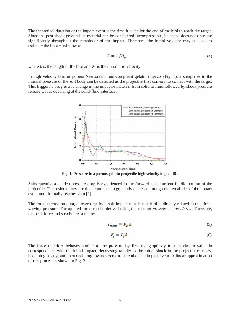
In high velocity bird or porous Newtonian fluid-compliant gelatin impacts (Fig. 1), a sharp rise in the internal pressure of the soft body can be detected as the projectile first comes into contact with the target. This triggers a progressive change in the impactor material from solid to fluid followed by shock pressure release waves occurring at the solid-fluid interface.
Fig. 1. Pressure in a porous gelatin projectile high velocity impact [8].
Subsequently, a sudden pressure drop is experienced in the forward and transient fluidic portion of the projectile. The residual pressure then continues to gradually decrease through the remainder of the impact event until it finally reaches zero [1].
The force exerted on a target over time by a soft impactor such as a bird is directly related to this time-varying pressure. The applied force can be derived using the relation pressure = force/area. Therefore, the peak force and steady pressure are:
(5)
(6)
The force therefore behaves similar to the pressure by first rising quickly to a maximum value in correspondence with the initial impact, decreasing rapidly as the initial shock in the projectile releases, becoming steady, and then declining towards zero at the end of the impact event. A linear approximation of this process is shown in Fig. 2.
NASA/TM—2014-218397 5
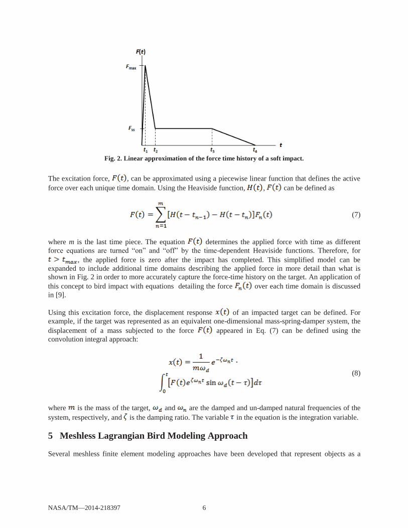
Fig. 2. Linear approximation of the force time history of a soft impact.
The excitation force, , can be approximated using a piecewise linear function that defines the active force over each unique time domain. Using the Heaviside function, , can be defined as
(7)
where m is the last time piece. The equation determines the applied force with time as different force equations are turned “on” and “off” by the time-dependent Heaviside functions. Therefore, for
, the applied force is zero after the impact has completed. This simplified model can be expanded to include additional time domains describing the applied force in more detail than what is shown in Fig. 2 in order to more accurately capture the force-time history on the target. An application of this concept to bird impact with equations detailing the force over each time domain is discussed in [9].
Using this excitation force, the displacement response of an impacted target can be defined. For example, if the target was represented as an equivalent one-dimensional mass-spring-damper system, the displacement of a mass subjected to the force appeared in Eq. (7) can be defined using the convolution integral approach:
(8)
where is the mass of the target, and are the damped and un-damped natural frequencies of the system, respectively, and is the damping ratio. The variable in the equation is the integration variable.
5 Meshless Lagrangian Bird Modeling Approach
Several meshless finite element modeling approaches have been developed that represent objects as a
NASA/TM—2014-218397 6
finite number of discrete particles that interact via an approximation or kernel function rather than a structured mesh. The range of influence and interaction with other particles can be defined through using this function. In meshless Lagrangian approaches, each node represents a particle with physical properties such as mass, volume, and pressure. Each particle experiences fluid forces based on the mass and number of surrounding particles and the kernel defining their interaction [10]. Closer particles exert more influence than those that are farther away. In this manner, particle interaction can be visualized as an inter-molecular attraction type force holding the particles together. The behavior of the particles is governed by the Navier-Stokes equations, numerically discretized for use with the particle approach [9].This might neglect the possible non-Newtonian nature of the transient fluid produced as a result of the fluid-solid interaction.
5.1 Bird Model Details
The bird was modeled as discrete particles using a Meshless Lagrangian approach on the explicit finite element platform Ls-Dyna. Several representative bird geometries have been proposed for both impact experiments utilizing bird surrogates and finite element models of high velocity bird impact. One of the most common configurations is a cylinder with rounded hemispherical ends [11].
A similar geometry was adapted for the employed particle modeling approach in thus work; the particles were arranged, evenly spaced, throughout a rounded-cylindrical volume to approximate the shape of a bird body. The ratio of total length to diameter for the bird geometry was 2.
It was necessary to define both a suitable material model and a pressure-volume state equation for the bird. As discussed above, the bird material begins changing from a solid to a fluid at the point of impact with a blade. Material at the blade/bird interface is rapidly liquefied, and the resulting impact shockwavepropagates through the bird much faster than the relative bird/blade velocity. For the majority of the interaction, the blade interacts with the gelatin-like fluid, and only interacts with the solid bird for a brief instant at the moment of impact. Therefore, it is justified to model the bird using a fluid material model for the entire impact event.
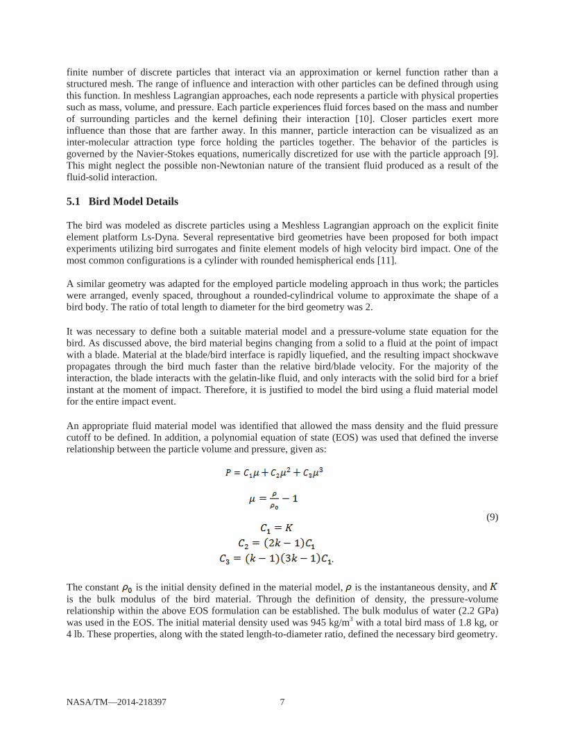
An appropriate fluid material model was identified that allowed the mass density and the fluid pressure cutoff to be defined. In addition, a polynomial equation of state (EOS) was used that defined the inverse relationship between the particle volume and pressure, given as:
.
(9)
The constant is the initial density defined in the material model, is the instantaneous density, and is the bulk modulus of the bird material. Through the definition of density, the pressure-volume relationship within the above EOS formulation can be established. The bulk modulus of water (2.2 GPa) was used in the EOS. The initial material density used was 945 kg/m3 with a total bird mass of 1.8 kg, or 4 lb. These properties, along with the stated length-to-diameter ratio, defined the necessary bird geometry.
NASA/TM—2014-218397 7
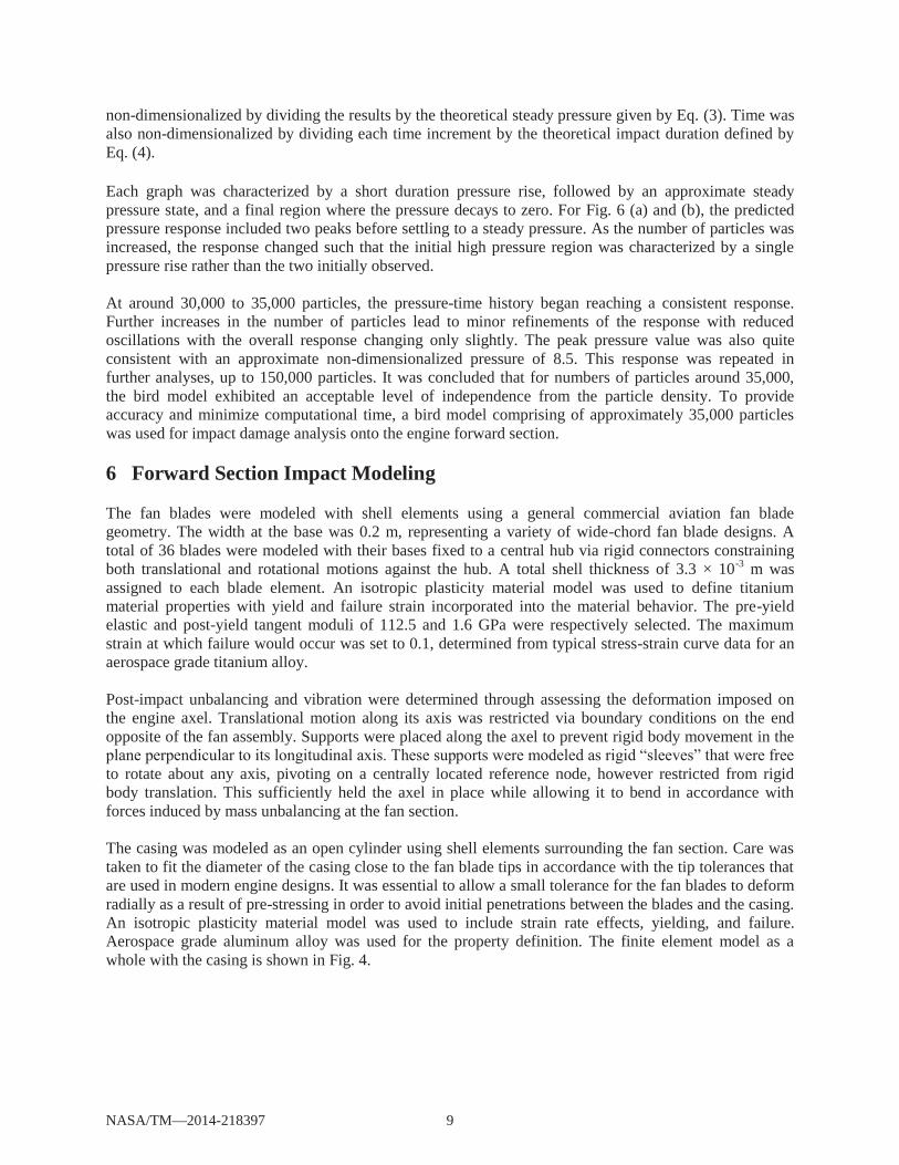
The variable is a non-dimensional material constant called the Hugoniot number or compressibility constant. This is adopted from the classical linear shockwave speed equation:
(10)
where is the speed of sound in the material, is the Hugoniot number, and and are the shockwave speed and initial velocity respectively, as defined previously. Prior studies have found to equal approximately 2 for biological materials including birds [12].
Simulations of the bird impacting a rigid plate were conducted and the pressure at the center of the impact region was recorded throughout the duration of the impact. The number of particles used to represent the bird was varied and the pressure-time history at the center of impact was compared. This was done in order to verify that a sufficient particle density was used such that the bird behavior was independent of the number of particles used in the simulation.
5.2 Impact Results
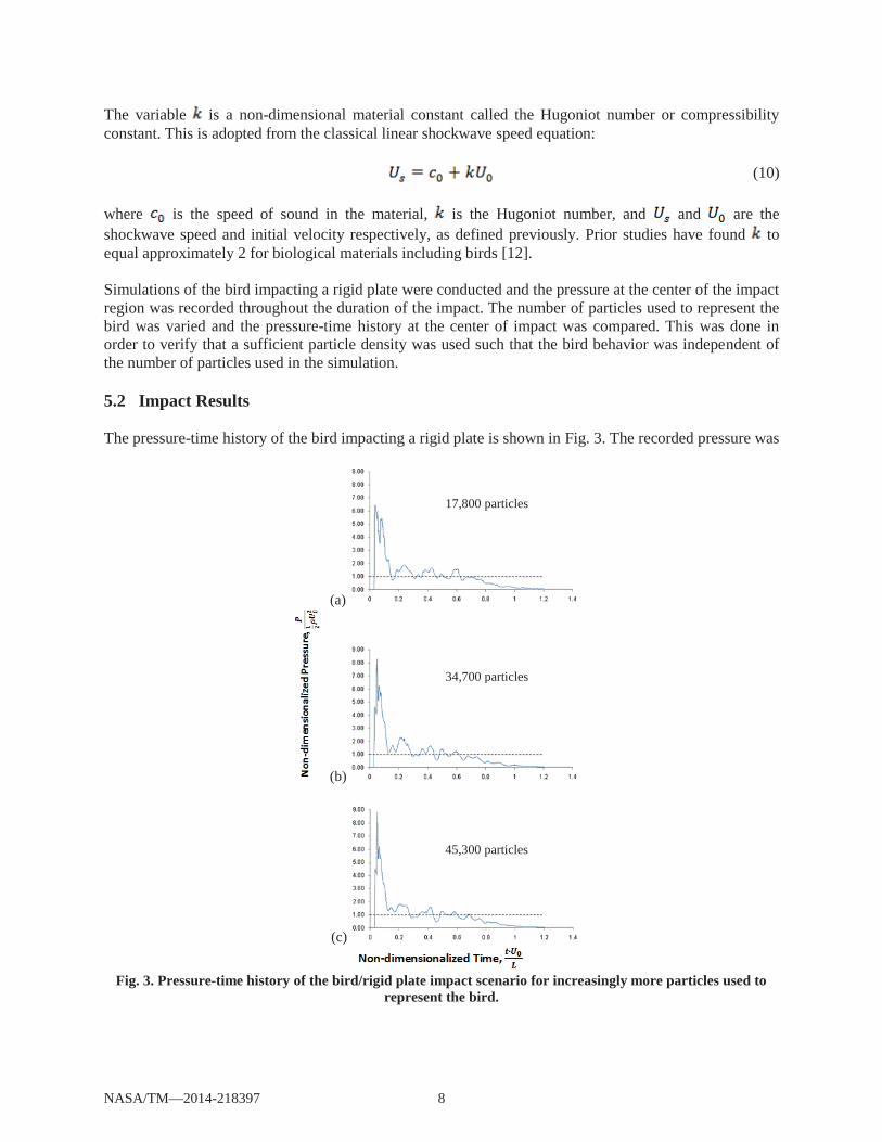
The pressure-time history of the bird impacting a rigid plate is shown in Fig. 3. The recorded pressure was
(a)
(b)
(c)
Fig. 3. Pressure-time history of the bird/rigid plate impact scenario for increasingly more particles used to represent the bird.
17,800 particles
34,700 particles
45,300 particles
NASA/TM—2014-218397 8
non-dimensionalized by dividing the results by the theoretical steady pressure given by Eq. (3). Time was also non-dimensionalized by dividing each time increment by the theoretical impact duration defined by Eq. (4).
Each graph was characterized by a short duration pressure rise, followed by an approximate steady pressure state, and a final region where the pressure decays to zero. For Fig. 6 (a) and (b), the predicted pressure response included two peaks before settling to a steady pressure. As the number of particles was increased, the response changed such that the initial high pressure region was characterized by a single pressure rise rather than the two initially observed.
At around 30,000 to 35,000 particles, the pressure-time history began reaching a consistent response. Further increases in the number of particles lead to minor refinements of the response with reduced oscillations with the overall response changing only slightly. The peak pressure value was also quite consistent with an approximate non-dimensionalized pressure of 8.5. This response was repeated in further analyses, up to 150,000 particles. It was concluded that for numbers of particles around 35,000, the bird model exhibited an acceptable level of independence from the particle density. To provide accuracy and minimize computational time, a bird model comprising of approximately 35,000 particles was used for impact damage analysis onto the engine forward section.
6 Forward Section Impact Modeling
The fan blades were modeled with shell elements using a general commercial aviation fan blade geometry. The width at the base was 0.2 m, representing a variety of wide-chord fan blade designs. A total of 36 blades were modeled with their bases fixed to a central hub via rigid connectors constraining both translational and rotational motions against the hub. A total shell thickness of 3.3 × 10⁻³ m was assigned to each blade element. An isotropic plasticity material model was used to define titanium material properties with yield and failure strain incorporated into the material behavior. The pre-yield elastic and post-yield tangent moduli of 112.5 and 1.6 GPa were respectively selected. The maximum strain at which failure would occur was set to 0.1, determined from typical stress-strain curve data for an aerospace grade titanium alloy.
Post-impact unbalancing and vibration were determined through assessing the deformation imposed on the engine axel. Translational motion along its axis was restricted via boundary conditions on the end opposite of the fan assembly. Supports were placed along the axel to prevent rigid body movement in the plane perpendicular to its longitudinal axis. These supports were modeled as rigid “sleeves” that were free to rotate about any axis, pivoting on a centrally located reference node, however restricted from rigid body translation. This sufficiently held the axel in place while allowing it to bend in accordance with forces induced by mass unbalancing at the fan section.
The casing was modeled as an open cylinder using shell elements surrounding the fan section. Care was taken to fit the diameter of the casing close to the fan blade tips in accordance with the tip tolerances that are used in modern engine designs. It was essential to allow a small tolerance for the fan blades to deform radially as a result of pre-stressing in order to avoid initial penetrations between the blades and the casing. An isotropic plasticity material model was used to include strain rate effects, yielding, and failure. Aerospace grade aluminum alloy was used for the property definition. The finite element model as a whole with the casing is shown in Fig. 4.
NASA/TM—2014-218397 9
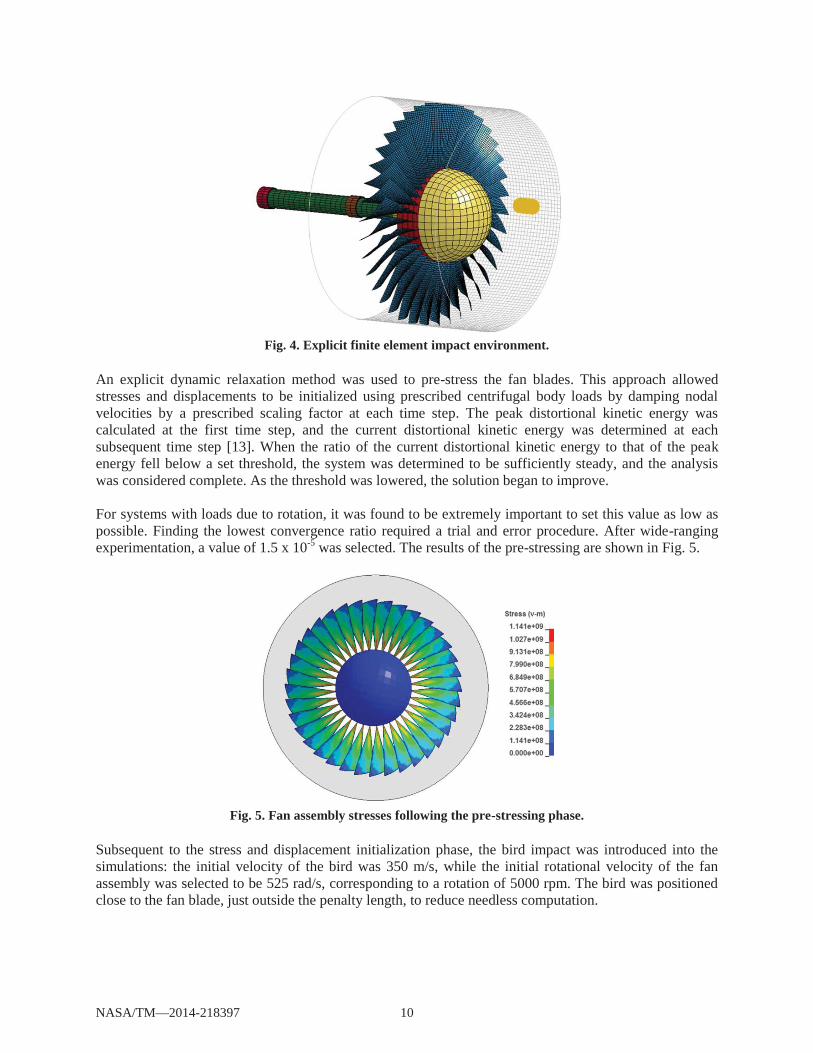
Fig. 4. Explicit finite element impact environment.
An explicit dynamic relaxation method was used to pre-stress the fan blades. This approach allowed stresses and displacements to be initialized using prescribed centrifugal body loads by damping nodal velocities by a prescribed scaling factor at each time step. The peak distortional kinetic energy was calculated at the first time step, and the current distortional kinetic energy was determined at each subsequent time step [13]. When the ratio of the current distortional kinetic energy to that of the peakenergy fell below a set threshold, the system was determined to be sufficiently steady, and the analysis was considered complete. As the threshold was lowered, the solution began to improve.
For systems with loads due to rotation, it was found to be extremely important to set this value as low as possible. Finding the lowest convergence ratio required a trial and error procedure. After wide-ranging experimentation, a value of 1.5 x 10⁻⁵ was selected. The results of the pre-stressing are shown in Fig. 5.
Fig. 5. Fan assembly stresses following the pre-stressing phase.
Subsequent to the stress and displacement initialization phase, the bird impact was introduced into the simulations: the initial velocity of the bird was 350 m/s, while the initial rotational velocity of the fan assembly was selected to be 525 rad/s, corresponding to a rotation of 5000 rpm. The bird was positioned close to the fan blade, just outside the penalty length, to reduce needless computation.
NASA/TM—2014-218397 10
6.1 Bird Impact Results
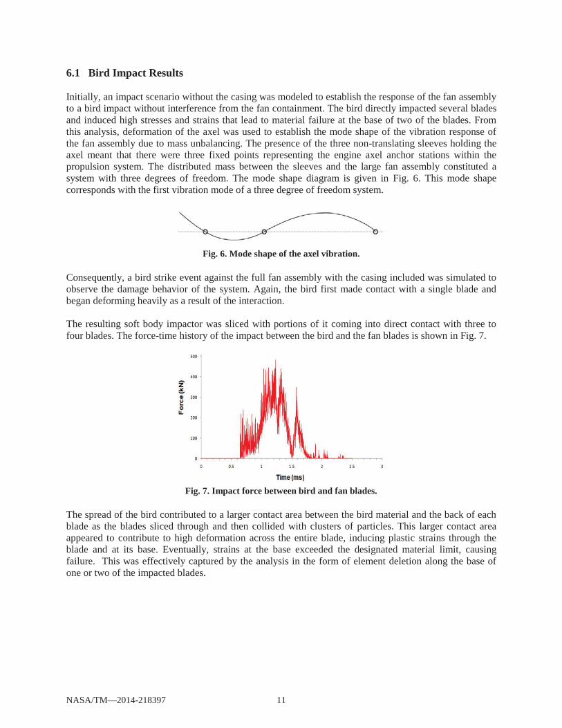
Initially, an impact scenario without the casing was modeled to establish the response of the fan assembly to a bird impact without interference from the fan containment. The bird directly impacted several blades and induced high stresses and strains that lead to material failure at the base of two of the blades. From this analysis, deformation of the axel was used to establish the mode shape of the vibration response of the fan assembly due to mass unbalancing. The presence of the three non-translating sleeves holding the axel meant that there were three fixed points representing the engine axel anchor stations within the propulsion system. The distributed mass between the sleeves and the large fan assembly constituted a system with three degrees of freedom. The mode shape diagram is given in Fig. 6. This mode shape corresponds with the first vibration mode of a three degree of freedom system.
Fig. 6. Mode shape of the axel vibration.
Consequently, a bird strike event against the full fan assembly with the casing included was simulated to observe the damage behavior of the system. Again, the bird first made contact with a single blade and began deforming heavily as a result of the interaction.
The resulting soft body impactor was sliced with portions of it coming into direct contact with three to four blades. The force-time history of the impact between the bird and the fan blades is shown in Fig. 7.
Fig. 7. Impact force between bird and fan blades.
The spread of the bird contributed to a larger contact area between the bird material and the back of each blade as the blades sliced through and then collided with clusters of particles. This larger contact area appeared to contribute to high deformation across the entire blade, inducing plastic strains through the blade and at its base. Eventually, strains at the base exceeded the designated material limit, causing failure. This was effectively captured by the analysis in the form of element deletion along the base of one or two of the impacted blades.
NASA/TM—2014-218397 11
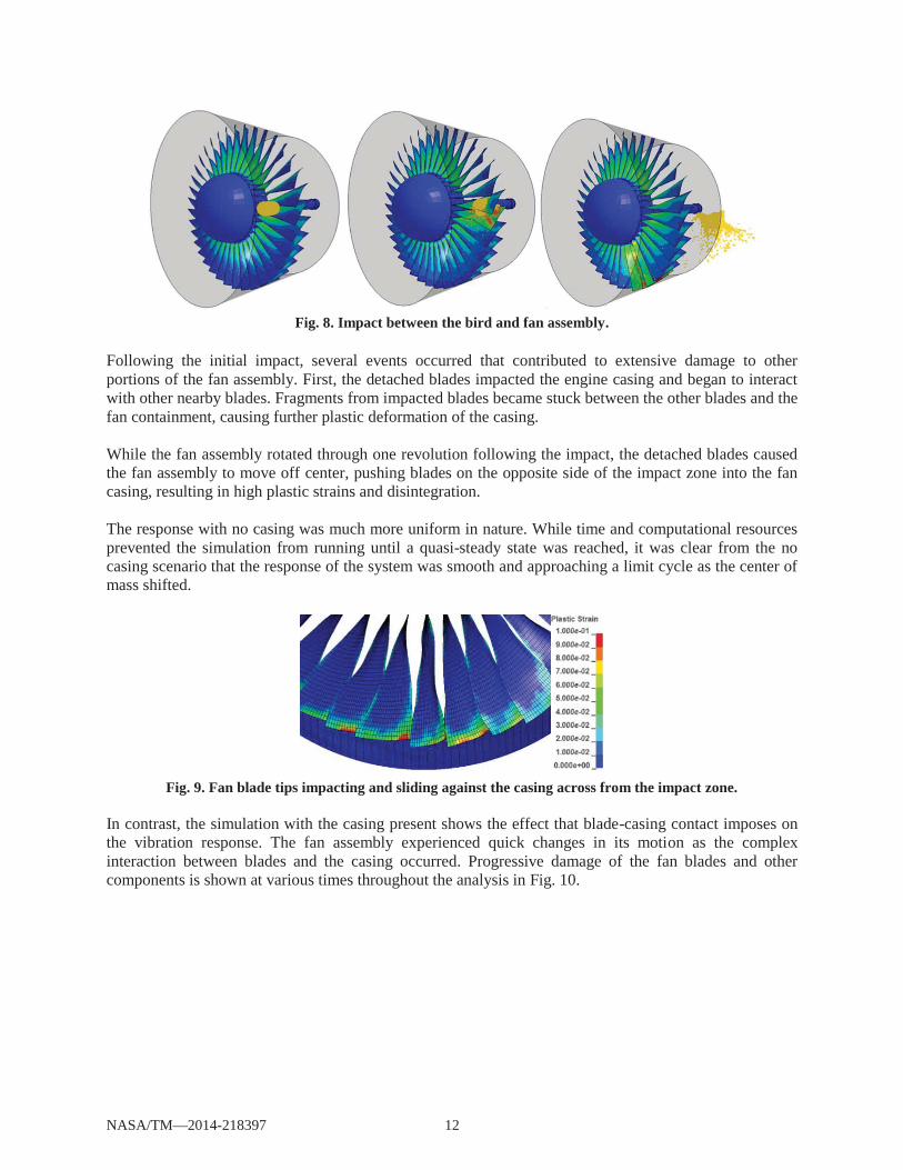
Fig. 8. Impact between the bird and fan assembly.
Following the initial impact, several events occurred that contributed to extensive damage to other portions of the fan assembly. First, the detached blades impacted the engine casing and began to interact with other nearby blades. Fragments from impacted blades became stuck between the other blades and the fan containment, causing further plastic deformation of the casing.
While the fan assembly rotated through one revolution following the impact, the detached blades caused the fan assembly to move off center, pushing blades on the opposite side of the impact zone into the fan casing, resulting in high plastic strains and disintegration.
The response with no casing was much more uniform in nature. While time and computational resources prevented the simulation from running until a quasi-steady state was reached, it was clear from the no casing scenario that the response of the system was smooth and approaching a limit cycle as the center of mass shifted.
Fig. 9. Fan blade tips impacting and sliding against the casing across from the impact zone.
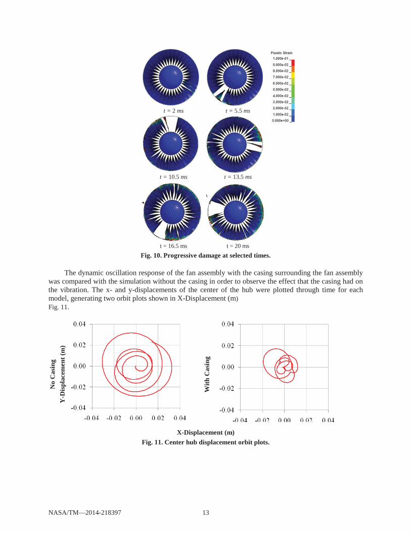
In contrast, the simulation with the casing present shows the effect that blade-casing contact imposes on the vibration response. The fan assembly experienced quick changes in its motion as the complex interaction between blades and the casing occurred. Progressive damage of the fan blades and other components is shown at various times throughout the analysis in Fig. 10.
NASA/TM—2014-218397 12
t = 2 ms t = 5.5 ms
t = 10.5 ms t = 13.5 ms
t = 16.5 ms t = 20 msFig. 10. Progressive damage at selected times.
The dynamic oscillation response of the fan assembly with the casing surrounding the fan assembly was compared with the simulation without the casing in order to observe the effect that the casing had on the vibration. The x- and y-displacements of the center of the hub were plotted through time for each model, generating two orbit plots shown in X-Displacement (m) Fig. 11.
No
Cas
ing
Y-D
ispl
acem
ent (
m)
With
Cas
ing
X-Displacement (m) Fig. 11. Center hub displacement orbit plots.
NASA/TM—2014-218397 13
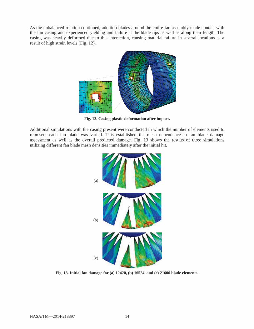
the fan casing and experienced yielding and failure at the blade tips as well as along their length. The casing was heavily deformed due to this interaction, causing material failure in several locations as a result of high strain levels (Fig. 12).
Fig. 12. Casing plastic deformation after impact.
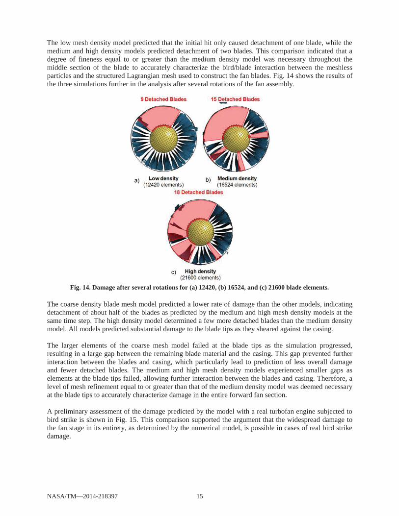
Additional simulations with the casing present were conducted in which the number of elements used to represent each fan blade was varied. This established the mesh dependence in fan blade damage assessment as well as the overall predicted damage. Fig. 13 shows the results of three simulations utilizing different fan blade mesh densities immediately after the initial hit.
(a)
(b)
(c)
Fig. 13. Initial fan damage for (a) 12420, (b) 16524, and (c) 21600 blade elements.
NASA/TM—2014-218397 14
As the unbalanced rotation continued, addition blades around the entire fan assembly made contact with
medium and high density models predicted detachment of two blades. This comparison indicated that a degree of fineness equal to or greater than the medium density model was necessary throughout the middle section of the blade to accurately characterize the bird/blade interaction between the meshless particles and the structured Lagrangian mesh used to construct the fan blades. Fig. 14 shows the results of the three simulations further in the analysis after several rotations of the fan assembly.
Fig. 14. Damage after several rotations for (a) 12420, (b) 16524, and (c) 21600 blade elements.
The coarse density blade mesh model predicted a lower rate of damage than the other models, indicating detachment of about half of the blades as predicted by the medium and high mesh density models at the same time step. The high density model determined a few more detached blades than the medium density model. All models predicted substantial damage to the blade tips as they sheared against the casing.
The larger elements of the coarse mesh model failed at the blade tips as the simulation progressed, resulting in a large gap between the remaining blade material and the casing. This gap prevented further interaction between the blades and casing, which particularly lead to prediction of less overall damage and fewer detached blades. The medium and high mesh density models experienced smaller gaps as elements at the blade tips failed, allowing further interaction between the blades and casing. Therefore, a level of mesh refinement equal to or greater than that of the medium density model was deemed necessary at the blade tips to accurately characterize damage in the entire forward fan section.
A preliminary assessment of the damage predicted by the model with a real turbofan engine subjected to bird strike is shown in Fig. 15. This comparison supported the argument that the widespread damage to the fan stage in its entirety, as determined by the numerical model, is possible in cases of real bird strike damage.
NASA/TM—2014-218397 15
The low mesh density model predicted that the initial hit only caused detachment of one blade, while the
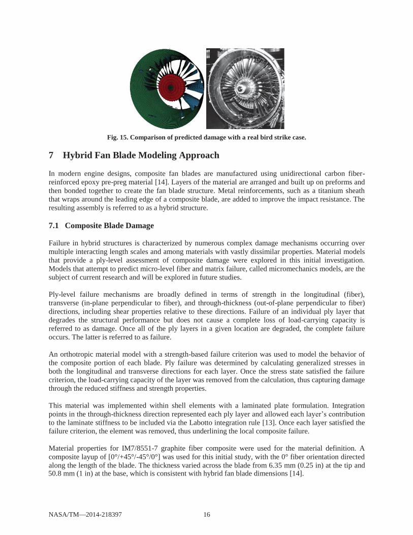
Fig. 15. Comparison of predicted damage with a real bird strike case.
7 Hybrid Fan Blade Modeling Approach
In modern engine designs, composite fan blades are manufactured using unidirectional carbon fiber-reinforced epoxy pre-preg material [14]. Layers of the material are arranged and built up on preforms and then bonded together to create the fan blade structure. Metal reinforcements, such as a titanium sheath that wraps around the leading edge of a composite blade, are added to improve the impact resistance. The resulting assembly is referred to as a hybrid structure.
7.1 Composite Blade Damage
Failure in hybrid structures is characterized by numerous complex damage mechanisms occurring over multiple interacting length scales and among materials with vastly dissimilar properties. Material models that provide a ply-level assessment of composite damage were explored in this initial investigation. Models that attempt to predict micro-level fiber and matrix failure, called micromechanics models, are the subject of current research and will be explored in future studies.
Ply-level failure mechanisms are broadly defined in terms of strength in the longitudinal (fiber), transverse (in-plane perpendicular to fiber), and through-thickness (out-of-plane perpendicular to fiber) directions, including shear properties relative to these directions. Failure of an individual ply layer that degrades the structural performance but does not cause a complete loss of load-carrying capacity is referred to as damage. Once all of the ply layers in a given location are degraded, the complete failure occurs. The latter is referred to as failure.
An orthotropic material model with a strength-based failure criterion was used to model the behavior of the composite portion of each blade. Ply failure was determined by calculating generalized stresses in both the longitudinal and transverse directions for each layer. Once the stress state satisfied the failure criterion, the load-carrying capacity of the layer was removed from the calculation, thus capturing damage through the reduced stiffness and strength properties.
This material was implemented within shell elements with a laminated plate formulation. Integration points in the through-thickness direction represented each ply layer and allowed each layer’s contribution to the laminate stiffness to be included via the Labotto integration rule [13]. Once each layer satisfied the failure criterion, the element was removed, thus underlining the local composite failure.
Material properties for IM7/8551-7 graphite fiber composite were used for the material definition. A composite layup of [0°/+45°/-45°/0°] was used for this initial study, with the 0° fiber orientation directed along the length of the blade. The thickness varied across the blade from 6.35 mm (0.25 in) at the tip and
NASA/TM—2014-218397 16
50.8 mm (1 in) at the base, which is consistent with hybrid fan blade dimensions [14].
7.2 Leading Edge Delamination
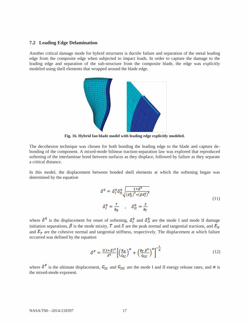
Another critical damage mode for hybrid structures is ductile failure and separation of the metal leading edge from the composite edge when subjected to impact loads. In order to capture the damage to the leading edge and separation of the sub-structure from the composite blade, the edge was explicitly modeled using shell elements that wrapped around the blade edge.
Fig. 16. Hybrid fan blade model with leading edge explicitly modeled.
The decohesion technique was chosen for both bonding the leading edge to the blade and capture de-bonding of the component. A mixed-mode bilinear traction-separation law was explored that reproduced softening of the interlaminar bond between surfaces as they displace, followed by failure as they separate a critical distance.
In this model, the displacement between bonded shell elements at which the softening began was determined by the equation
(11)
where is the displacement for onset of softening, and are the mode I and mode II damage initiation separations, is the mode mixity, and are the peak normal and tangential tractions, and and are the cohesive normal and tangential stiffness, respectively. The displacement at which failure occurred was defined by the equation
(12)
where is the ultimate displacement, and are the mode I and II energy release rates, and is the mixed-mode exponent.
NASA/TM—2014-218397 17
This cohesive model was implemented in the explicit FE code using tied a constraint between the titanium leading edge and the portion of the composite surrounded by the metal component. With the tied constraint approach, parts being coupled do not need to share similar geometries or meshes. This provides a convenient method of defining cohesive behavior between parts with very different shapes.
Cohesive parameters for the composite/metal bond were not available at the time of this study. As an approximation of the peak tractions and the mode I and II energy release rates, properties from carbon-fiber composite delamination experimental studies were obtained from the literature [15] and decreased by one-fourth before being applied, with the assumption that the composite/metal bond would form a weaker interface.
The titanium leading edge incorporated an elastic-plastic material model with a strain-based failure criterion. Properties for Ti-Al6-4V ASTM Grade 5 titanium alloy were used to define the leading edge behavior.
7.3 Pre-stress Analysis
Centripetal loads were applied to the hybrid fan blade using the same explicit DR analysis approach utilized for metal blades. Again, it was important to decrease the convergence tolerance as much as possible to arrive at a pre-stressed state sufficiently close to the true stresses for a given rotational speed to reduced unwanted stress oscillations at the beginning of the transient analysis.
8 Hybrid Fan Impact Modeling
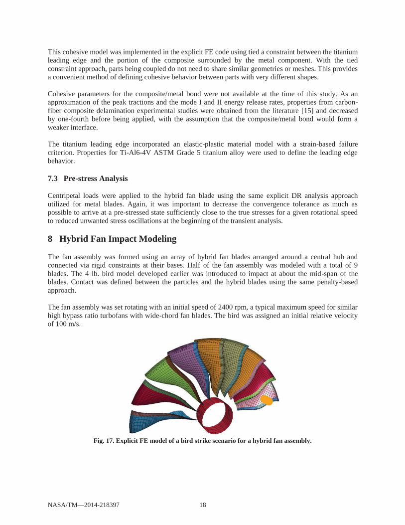
The fan assembly was formed using an array of hybrid fan blades arranged around a central hub and connected via rigid constraints at their bases. Half of the fan assembly was modeled with a total of 9 blades. The 4 lb. bird model developed earlier was introduced to impact at about the mid-span of the blades. Contact was defined between the particles and the hybrid blades using the same penalty-based approach.
The fan assembly was set rotating with an initial speed of 2400 rpm, a typical maximum speed for similar high bypass ratio turbofans with wide-chord fan blades. The bird was assigned an initial relative velocity of 100 m/s.
Fig. 17. Explicit FE model of a bird strike scenario for a hybrid fan assembly.
NASA/TM—2014-218397 18
8.1 Bird Impact Results
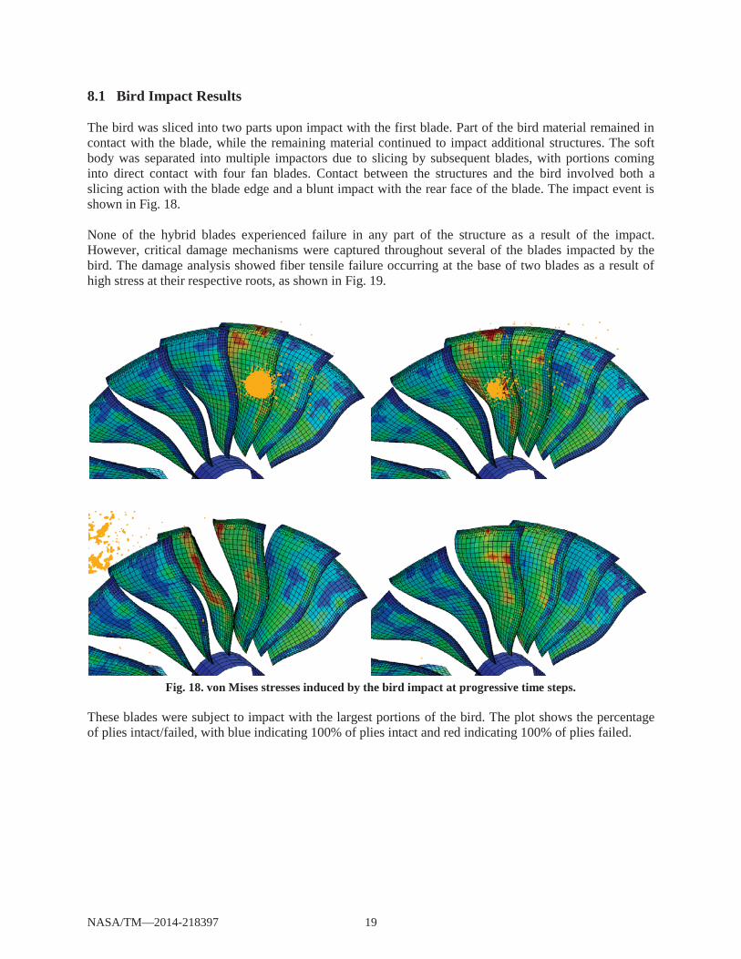
The bird was sliced into two parts upon impact with the first blade. Part of the bird material remained in contact with the blade, while the remaining material continued to impact additional structures. The soft body was separated into multiple impactors due to slicing by subsequent blades, with portions coming into direct contact with four fan blades. Contact between the structures and the bird involved both a slicing action with the blade edge and a blunt impact with the rear face of the blade. The impact event is shown in Fig. 18.
None of the hybrid blades experienced failure in any part of the structure as a result of the impact. However, critical damage mechanisms were captured throughout several of the blades impacted by the bird. The damage analysis showed fiber tensile failure occurring at the base of two blades as a result of high stress at their respective roots, as shown in Fig. 19.
Fig. 18. von Mises stresses induced by the bird impact at progressive time steps.
These blades were subject to impact with the largest portions of the bird. The plot shows the percentage of plies intact/failed, with blue indicating 100% of plies intact and red indicating 100% of plies failed.
NASA/TM—2014-218397 19
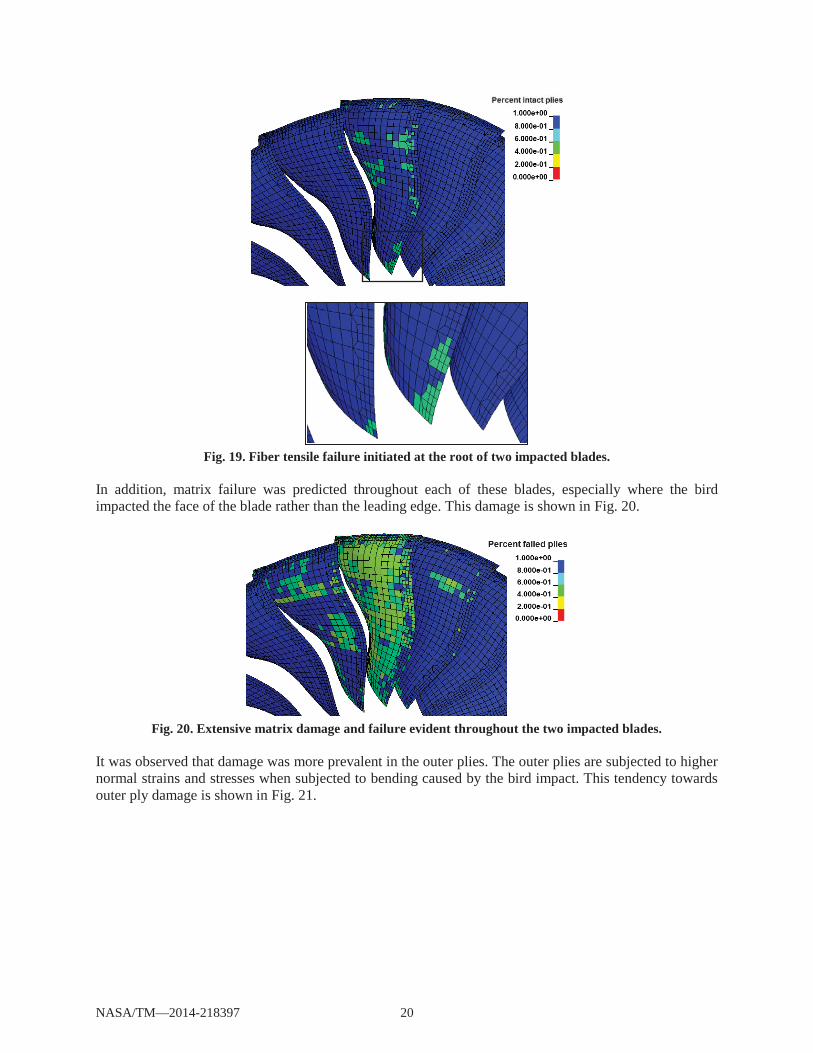
Fig. 19. Fiber tensile failure initiated at the root of two impacted blades.
In addition, matrix failure was predicted throughout each of these blades, especially where the bird impacted the face of the blade rather than the leading edge. This damage is shown in Fig. 20.
Fig. 20. Extensive matrix damage and failure evident throughout the two impacted blades.
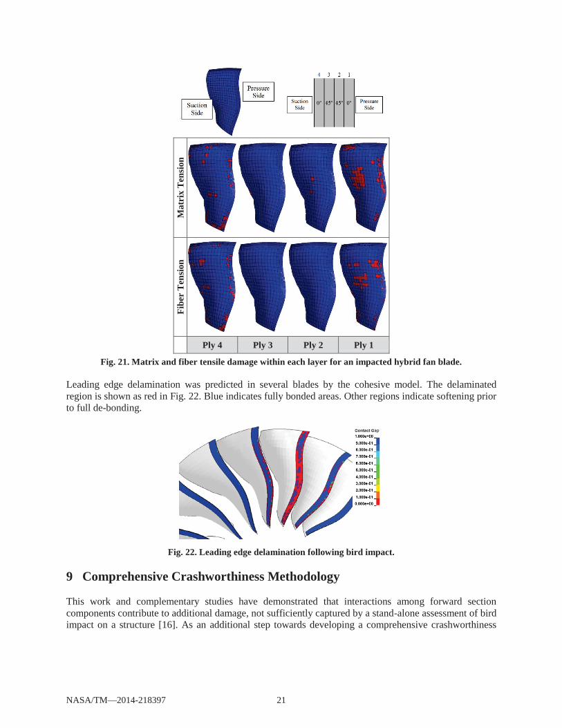
It was observed that damage was more prevalent in the outer plies. The outer plies are subjected to higher normal strains and stresses when subjected to bending caused by the bird impact. This tendency towards outer ply damage is shown in Fig. 21.
NASA/TM—2014-218397 20
Mat
rix
Ten
sion
Fibe
r T
ensi
on
Ply 4 Ply 3 Ply 2 Ply 1
Fig. 21. Matrix and fiber tensile damage within each layer for an impacted hybrid fan blade.
Leading edge delamination was predicted in several blades by the cohesive model. The delaminated region is shown as red in Fig. 22. Blue indicates fully bonded areas. Other regions indicate softening prior to full de-bonding.
Fig. 22. Leading edge delamination following bird impact.
9 Comprehensive Crashworthiness Methodology
This work and complementary studies have demonstrated that interactions among forward section components contribute to additional damage, not sufficiently captured by a stand-alone assessment of bird impact on a structure [16]. As an additional step towards developing a comprehensive crashworthiness
NASA/TM—2014-218397 21
methodology for hybrid engines, a fully coupled fluid-structural module is proposed. The requirements for this module and the platforms utilized will be detailed in the next report.
10 Conclusion
Research efforts focusing on the development of a detailed predictive modeling methodology for comprehensive analysis of bird strike and post-impact damage assessment in structural-hybrid jet engine forward sections are reported. The development of a transformative, aerospace propulsion design platform for evaluating the crashworthiness of future advanced structural engines is one of the main objectives of these studies. The novel methodology proposed offers the ability to capture the extent of intricate soft foreign object damage to fan blades resulting from direct initial impact, subsequent collisions with a number of other engine forward section parts and sub-components as well as associated fragmentation containment analysis. The full dynamic response prognosis in this methodology further encompasses blade-out, fan assembly unbalancing and vibrations, and subsequent engine casing shearing and shaving damage analyses, which remain unaddressed in many previous studies.
A novel numerical method for predicting damage and failure in hybrid jet engine fan blades subject to soft impact has also been developed. Critical damage mechanisms have been captured, such as composite fiber and matrix failure mechanisms, leading edge delamination, and material failure. This work shows promise for extending the forward section engine damage methodology to include hybrid fan structures.
The outlook of the investigations will include validations of the modules developed thus far by means of comparison with data obtained from variety of crashworthiness experiments. Overall, it is aimed to develop a comprehensive analysis platform for the assessment of hybrid engine designs that will reduce reliance on physical tests and can support future developments of advanced aerospace propulsion systems. Fluid-structural coupling will further enable the methodology to assess the performance loss caused by structural deformation and failure.
NASA/TM—2014-218397 22
References
[1] Wilbeck, J. S., and Barber, J. P. Bird impact loading. Shock and Vibration Bulletin, No. 47, 1978, p. 7. DOI: 0362-3874
[2] Siddens, A., and Bayandor, J. A soft impact predictive methodology for hybrid/composite propulsion systems. Proceedings of the 16th International Conference on Composite Structures,Nashville, Tennessee, January 9-12, 2012.
[3] Mao, R. H., Meguid, S. A., and Ng, T. Y. Finite element modeling of a bird striking an engine fan blade. Journal of Aircraft, Vol. 44, No. 2, 2007, pp. 583-596. DOI: 10.2514/1.24568
[4] Yupu, G. Foreign object damage to fan rotor blades of aeroengine part i: Experimental study of bird impact. Chinese Journal of Aeronautics, Vol. 20, No. 5, 2007, pp. 408-414.
[5] Meguid, S. A., Mao, R. H., and Ng, T. Y. Fe analysis of geometry effects of an artificial bird striking an aeroengine fan blade. International Journal of Impact Engineering, Vol. 35, No. 6, 2008, pp. 487-498. DOI: 10.1016/j.ijimpeng.2007.04.008
[6] Chevrolet, D., Audic, S., and Bonini, J. Bird impact analysis on a bladed disk. RTO AVT Symposium, Paris, France, 22-25 April, 2002.
[7] Sinha, S. K., Turner, K. E., and Jain, N. Dynamic loading on turbofan blades due to bird-strike. Journal of Engineering for Gas Turbines and Power, Vol. 133, 2011.
[8] Johnson, A. F., and Holzapfel, M. Modelling soft body impact on composite structures. Journal of Composite Structures, Vol. 61, 2003, p. 10. DOI: 10.1016/S0263-8223(03)00033-3
[9] Siddens, A., and Bayandor, J. A discrete meshless lagrangian based approach for soft impact damage modeling in advanced propulsion systems. ASME International Mechanical Engineering Congress & Exposition, Vancouver, British Columbia, 12-18 November, 2010.
[10] Liu, G. R., and Liu, M. B. Smoothed particle hydrodynamics: A meshfree particle method. World Scientific Publishing Co. Pte. Ltd., 5 Toh Tuck Link, Singapore, 2003.
[11] Bayandor, J., Johnson, A. F., Thomson, R. S., and Joosten, M. Impact damage modelling of composite aerospace structures subject to bird-strike. 25th International Congress of the Aeronautical Sciences, Hamburg, Germany, 2006.
[12] Nagayama, K., Mori, Y., Motegi, Y., and Nakahara, M. Shock hugoniot for biological materials. Shock Waves, Vol. 15, No. 3, 2006, pp. 267-275. DOI: 10.1007/s00193-006-0030-5
[13] Ls-dyna theory manual, Livermore Software Technology Corporation, 2006.
[14] Marsh, G. Composites get in deep with new-generation engines, Reinforced Plastics, Vol. 50, No. 11, 22 December, 2006, pp. 26-29.
[15] Ilyas, M., Lachaud, F., Espinosa, C., and Salaün, M. Dynamic delamination of aeronautic structural composites by using cohesive finite elements. 17th International Conference on Composite Materials, Edinburgh, Scotland, 27-31 July, 2009.
[16] Siddens, A., and Bayandor, J. An extensive crashworthiness methodology for advanced propulsion systems - Part II: Detailed damage & vibration instability analysis of jet engine forward sections. 49th AIAA Aerospace Sciences Meeting, Orlando, Florida, 2010.
NASA/TM—2014-218397 23