DETAILED INSTALLATION GUIDE - · PDF file• Oscillating cutting tool – very...
20
Always review your local building codes for specific preparation of the substrate wall prior to applying URESTONE. Should you have any questions about or on the preparation, please contact your local building code office. e Manufacturer has provided these suggested instructions as an installation guideline. e manufacturer does not offer any installation services other than these guidelines, nor has any control over the installation of URESTONE panels. It is the responsibility of the general contractor and/or the installer to ensure that the URESTONE products are installed in accordance with these instructions and any applicable building codes. Our products install very easily and only require typical wood working and simple construction tools such as the following: Key Tools: • Circular saw (cordless or corded) – with fine plywood blade – this is best tool for cutting straight line cuts. • Jigsaw – with fine tooth blade – this is a good versatile tool for trimming, cut outs, straight cuts (does not cut as straight typi- cally as a circular saw. • Oscillating cutting tool – very versatile tool that is typically is better than a jigsaw for trimming and cutouts and quick adjust- ments. •Cordless drill / screw gun Other Tools •A level to ensure your first row is level. • A small rubber mallet – optional. •A caulk gun. •Small paint brush Making Straight Cuts In instances where access to a table saw is not available, a guide fence is recommended when straight and precise cuts are re- quired . is is especially important for areas that have tight fits and when mitering inside and outside corners. • Anytime that power tools are used for cutting panels be sure and wear safety eye gear, ear plugs, and a dust mask. D ETAILED I NSTALLATION G UIDE e first step is to determine the amount of product(s) that you will need to complete your project. First determine the vertical wall space (square footage) that will be required to properly cover the area of your choice. *NOTE: To properly measure, use a tape measure and determine the width (lineal length) and height of the area (Multiply the width by the height). Inquire to the exact square foot cover- age of the particular product that you’re buying and divide the square foot measurement by the square foot of coverage of the product. Also, should you have any windows or doors, along the wall area, measure using the same formula as above, and simply subtract that area from the overall measurement. Since the Urestone is a larger panel, it is recommended that you error on the high side of what you might need to insure that you do not run out of material and have to order additional panels that will be a different “color lot”. 1.1 Estimating e Required Materials It is important to store the URESTONE faux panels flat on a sur- face in order to avoid distorting. If panels are stored in an upright position and do bow or distort , lay them flat (in the sun or warm area) and they will self‐correct. Panels are manufactured using polyurethane foam; therefore, these panels must be handled properly to ensure the best results. Upon receiving the shipment, allow the panels to acclimate to the climate for 24 – 48 hours prior to installation, and begin the install at the coolest part of the day. is practice minimizes the product expansion and contraction issues of synthetic materi- als. Never store the panels in direct sunlight before installing and cover with white or reflective plastic covering. If faux panels have been stored under hot conditions, allow the simulated panels to cool down to normal temperature before installation. If they are installed while hot—they panels will contract leaving larger gaps between panels once they cool or as the seasons cools down. If faux panels have been stored at room temperature or cooler, you may install faux panels immediately. 1.2 Storing & Conditioning Urestone Panels 1.4 Tools Required 1.3 Safety Gear 1 •Square / tape measure •Saw guide with clamps •Grinder with masonry wheel
Transcript of DETAILED INSTALLATION GUIDE - · PDF file• Oscillating cutting tool – very...

Always review your local building codes for specific preparation of the substrate wall prior to applying URESTONE. Should you haveany questions about or on the preparation, please contact your local building code office. The Manufacturer has provided these suggested instructions as an installation guideline. The manufacturer does not offer any installation services other than these guidelines, nor has any control over the installation of URESTONE panels. It is the responsibility of the general contractor and/or the installer to ensure that the URESTONE products are installed in accordance with these instructions and any applicable building codes.
Our products install very easily and only require typicalwood working and simple construction tools suchas the following:
Key Tools: • Circular saw (cordless or corded) – with fine plywood blade – this is best tool for cutting straight line cuts.• Jigsaw – with fine tooth blade – this is a good versatile tool for trimming, cut outs, straight cuts (does not cut as straight typi-cally as a circular saw.• Oscillating cutting tool – very versatile tool that is typically is better than a jigsaw for trimming and cutouts and quick adjust-ments. •Cordless drill / screw gun
Other Tools
•A level to ensure your first row is level. • A small rubber mallet – optional.•A caulk gun.•Small paint brush
Making Straight CutsIn instances where access to a table saw is not available, a guide fence is recommended when straight and precise cuts are re-quired . This is especially important for areas that have tight fits and when mitering inside and outside corners.
• Anytime that power tools are used for cutting panels be sure and wear safety eye gear, ear plugs, and a dust mask.
DETAILED INSTALLATION GUIDE
The first step is to determine the amount of product(s) that youwill need to complete your project.First determine the vertical wall space (square footage) that willbe required to properly cover the area of your choice.*NOTE: To properly measure, use a tape measure and determinethe width (lineal length) and height of the area (Multiplythe width by the height). Inquire to the exact square foot cover-age of the particular product that you’re buying and divide thesquare foot measurement by the square foot of coverage of theproduct. Also, should you have any windows or doors, along thewall area, measure using the same formula as above, and simplysubtract that area from the overall measurement. Since theUrestone is a larger panel, it is recommended that you error onthe high side of what you might need to insure that you do notrun out of material and have to order additional panels that willbe a different “color lot”.
1.1 Estimating The Required Materials
It is important to store the URESTONE faux panels flat on a sur-face in order to avoid distorting. If panels are stored in an upright position and do bow or distort , lay them flat (in the sun or warm area) and they will self‐correct.
Panels are manufactured using polyurethane foam; therefore, these panels must be handled properly to ensure the best results. Upon receiving the shipment, allow the panels to acclimate to the climate for 24 – 48 hours prior to installation, and begin the install at the coolest part of the day. This practice minimizes the product expansion and contraction issues of synthetic materi-als. Never store the panels in direct sunlight before installing and cover with white or reflective plastic covering.If faux panels have been stored under hot conditions, allow the simulated panels to cool down to normal temperature before installation. If they are installed while hot—they panels will contract leaving larger gaps between panels once they cool or as the seasons cools down. If faux panels have been stored at room temperature or cooler, you may install faux panels immediately.
1.2 Storing & Conditioning Urestone Panels
1.4 Tools Required
1.3 Safety Gear
1
•Square / tape measure •Saw guide with clamps •Grinder with masonry wheel

DRIP EDGE FLASHINGWhile drip edge flashing is not a requirement with the URESTONE system, it has the advantage of establishing a level ledge to start the panels on. It also aids in draining any water away from building walls.
2.1 Expansion And Contraction
All material will expand and contract with temperature changes in exterior applications, but synthetic materials like Urestone have a little more movement. Due to the foam layer, the URESTONE system insulates itself from most of the effects of expansion due to heat (except on the side of the project that faces the southern sun side exposure in typically hot regions —since the surface on the sun side could get a hot as 160 degree with dark colors.) Shrinkage can occur more frequently. General shrinkage of the 8 ft. panels once installed can be upto a 1/4—3/8”. So it is recom-mended that the panels be tightly interlocked together panel by panel. Shrinkage on exterior applications can be minimized by using the recommended screws per panel and following the gluing process between panels ( see section 4 & 5 for more details)
2.3 Flashing (as needed)
2.2 Setting Up A Level LineIt is advised that you start the project by setting up a level line across the wall that you are applying the panels to. After the first course has been installed level, the subsequent levels should remain level.When adding URESTONE on multiple sides of a building, before starting the project, determine the lowest and highest point on the project and adjust the first installation level accordingly. In the case of the example in the drawing , if you were to install a 42” wainscot panel at point “A” it would be at full height at that point, and cut at a slope towards point “B”. one would cut the bottom panel to fit slope of the ground level. At the front of the building, point “B” to point C and the panels for the entire front side might be cut at 36”.
There are two corner options to use with the full 4’ x 8’ ft panels which are “keyed” corners and “keyless” corners (Typically the wainscot panels only have the keyless corners available). Most people prefer the “Key Corners” since they provide the most natural transition and will work if there is a break in the system (like a door or a bump out). If there are no breaks in the project, then it is best to start and end with a “keyless corner”. See section 8.1 for the details of the corners.
WAINSCOT FLASHINGIf a URESTONE “wainscot” series panel is being installed, using a top flashing is an optional practice. However, it is a recommended procedure for this system because it provides both waterproofing properties and also provides a sharp and clean transition between the building and the panel. Once the level line is established on the building, the flashing should be installed at that level. Then the wainscot panels are installed tightly against this flashing. Some panels may need to be cut to fit between the flashing and the ground level or drip edge.
2
2.0 GENERAL PANEL INSTALLATION OVERVIEW
2.4 Start The Installation With The Corners
Top Flashing
Bottom DripEdge

2.8 Installing Multiple Levels of Panels
The preferred method of handling multiple levels is to stagger each layer by 1/2 a panel. This can be done eas-ily when using keyless corners. The only way to utilize this method with keyed corners, is if that pattern has a specifically designed half panel with keys on both ends or to create a 1/2 panel on patterns like brick.
**see website to determine which patterns have a 1/2 panel (4x4).
2.6 Screwing & Gluing Process
The process of attaching panels to the wall structure is a combination of using screws and using adhesive where the panels connect together. Screws are installed around the perimeter and in the grout lines within the panels. Adhesive is applied between the keys and shiplap joint.
• See Section 6.0 for Screwing Recommendations • See Section 5.0 for further Adhesive Recommendations.
Adhesive or the supplied polyurethane scealant is to be applied to the tongue as the panels are installed. This reduces/eliminates shirnkage.
2.7 Terminating a Wall
Adding the last panel - Once a point is reached where a full panel is too large to place between the panel and the corner /end of the wall, you will need to measure the distance from the inside of the deepest key to the wall (figure A). Mark this distance on the back of the next panel and cut accordingly, preferably using a circular saw (figure B).
If corner pieces are not used- the panels may be mitered for an easy corner wrap. See separate instructions on mitering corners.Beginning with the next row of panels, stagger the seams to form a more natural appearance. Continue this process onto the next vertical row, and the next, until the desired height is reached.
5
3
2.0 GENERAL PANEL INSTALLATION OVERVIEW
keyed corner
Figure A. Figure B
Step 1.Add screws through tongue and within panel.
Step 2.Add adhesive or approved polyurathane caulk on tongue.
Step 3.Add screws through keys to interlocking ones.
keyless corner Side View

The optimum system to use with the URESTONE system is a combination of building wrap followed by a drainage mat. The drainage mat has deeper spacing than a drainage wrap system. Follow manu-facturers recommendation for installation details
3.3 Drainage Mat
Prior to applying the URESTONE system, the building must have the proper building wrap and drainage mat system. Consult with your proper building codes for up to date requirements but in general the following process is typically required:
3.1 Building Wrap
The primary requirement is to follow the local building codes. The URESTONE system should not be considered a completely waterproofing system and as a result, a high quality building wrap system is the minimum requirement. However, we strongly recommend using a minimum of a “drainage wrap” or a drainage mat system (see below).
A drainage wrap is a building wrap with a built in spacer system which allows some drainage behind the panel. This type of system is recommended in wet climates.
3.2 Drainage Wrap
Many building drainage systems have a base drainage channel to optimize their system. In high rain zones, the use of this channel is recommended with the URESTONE system. It will also serve as a level starting system.
3.4 Base Drainage Channel/Drip Edge Flashing
Window and door openings are typically a common area for potential waterproofing problems. The URESTONE system and typical building codes require special attention to this aspect.Our specification for these types of openings follow the recommendations of typical building code and building wrap manufacturers of using multiple layers of waterproofing tapes and flashings on windows and door openings.
3.5 Sealing All Openings
OTHER WATERPROOFING DETAILS
3.0 WATER RESISTIVE BARRIER (WRB) APPLICATION
4

Fasteners should be placed in the grout lines of the TEXTURE PANEL or in an inconspicuous place. All screw heads should be counter sunk about 1/8” into the stone.
See 6.4 for caulking screws section.
Recommended Screw Placement For Exterior
For exterior applications the panel must be fastened a minimum of every 2 ft . It is important in high wind regions and on the sun side of the building to add some additional screws around the perimeter. See the chart for the recom-mended number of screws required.
No. of Screws
4.3 Amount Of Screws Required:
When applying the URESTONE panels, the use of screws is recommended as the primary method of attaching pan-els to walls and columns. In some applications, a combination of screws and adhesive is recommended.
4.0 SCREW RECOMMENDATIONS
4.1 Screw RecommendationsThe URESTONE Panel can be fastened over wood substrates using coarse thread exterior deck screws, masonry substrates require concrete “TAPCON” type screws (pre-drilling with hammer drill will be required), and steel substrates using self tapping metal screws. The screws must be ex-terior grade for outside applications (Painted, Galvanization or Stainless) and must penetrate the substrate a minimum of 3/4 ”. Typically 2 1/2”-3” will work for most applications but depends on thickness of the panel.
Colored deck screws can be used for most applications. Use a color that is closest to the stone panel color. However, caulk will be applied over the screw.
4.2 Placement Of Screws
5
Interior Exterior 2 ft x 4 ft ~6 ~104 ft x 8 ft ~10 ~18Wainscor ~4 ~15
Wainscot Panels
4’ x 8’ PanelsIt is also recommended to glue the keys together on exterior applications. (see Adhesive Recommendation section)
2’ x 4’ Panels
recess screw below surface
Apply screw in mortar joint
Apply screw at an angle below a large stone

Our primary adhesive recommendation is a polyurethane construction adhesive such as PL Polyurethane Adhesive. We do not recommend non polyurethane construction adhesives or similar general purpose adhesives.We have also found that “Great Stuff ”—a polyurethane foam in a can, has provided good results and is cost effective. It is good for ad-dressing surfaces with irregular profiles. However, contact Replications Unlimited for specific approval and instructions of how to use it.
5.0 ADHESIVE RECOMMENDATIONS AND DETAILS
The use of adhesive should not be used directly over applications that are using building wrap or waterproofing sheets. All surface areas must be clean, dry and free of oily or loose material for optimum results.Adhesive is typically used in exterior applications in attaching the panels to concrete and concrete wall block applications. It can also be used for attaching the URESTONE panels directly to insulation boards, construction boards (plywood, OSB, cement board) and existing EFIS systems when building wraps are not necessary. The use of adhesive can reduce the amount of screws in the range of 25—35 %. Adhesive is optional for interior applications and will also reduce the amount of screws required by 35—50%.The use of adhesive will also reduce the expansion / contraction of the system in exterior applications.
5.2 Type Of Adhesive
6
The amount of required adhesive is more critical for exterior applications than interior applications due to wind uplift issues and expansion / contraction issues. Apply a minimum 3/8” bead to the backside of the panel and apply the adhesive similar to figure 5.3 in sections that will allow water to channel behind the panel and to eliminate being trapped.
5.3 Amount Of Adhesive
Size of Adhesive Tube 10 oz. 28 oz.2 ft x 4 ft 1/3 1/124 ft x 8 ft 1 1/3
Size of Adhesive Tube 10 oz. 28 oz.2 ft x 4 ft 5 24 ft x 8 ft 3 1
5.1 General Recommendations
Figure 5.3
Amount of Adhesive Per Panel
Number of Panels Per Tube

Step 1 - Screw panel to building. Starting with the tongues.
The Urestone can have shrinkage of 1/8—1/4” but this aspect can be reduced or eliminated if the panels are properly screwed to the wall system and if the keys are glued together at the interlocking keys. Since most buildings use a building wrap system, the keys cannot be glued directly to the wall substrate. As a result, it is important to glue the shiplap tongue together.
5.4 Gluing the panels together
When mitering corners instead of using the URESTONE existing keyed and keyless corners, it is important to glue the miter with PL Polyurethane adhesive or TREMCO 100 caulk/adhesive.
5.5 Gluing Mitered Joints
7
Step 2 - Apply polyurethane adhesive or approved polyurethane caulk on tongue.
Step 3 - Interlock the keys of second panel into first panel. Add screws in keys of second panel to secure the keys together.
Glue to angle for extra strength

6.0 CAULKING AND FINISHING PROCEDURES
6.1 Caulk Types and SpecsThe caulk that we recommend or supply is typically available in colors (to match the color of the panel or grout color as close as possible) and has the option to have a sand texture to match the grout texture.
Consult Replications Unlimited for the current caulk recom-mendation for your specific project. We are working with sev-eral different suppliers of Acrylic, Polyurethane and Silicone sealants that each have their advantages.
*The polyurethane caulk can also be used as the adhesive for glueing the tongue and groove keys between the panels. See 5.4 for this detail.
Be sure to consult the instructions printed on the caulk tubes for specific requirements, but typically the sealants will not cure properly unless they are applied at 50 degrees for 4-6 hours.
8
6.5 Caulking Recessed Screws
The colored caulk is also de-signed to be used to cover up the recessed screw areas. Typically the screws should be placed in the grout areas and the same technique outlined in caulking the grout areas. If the screw in the middle of the stone, a non textured caulk may be necessary instead of a textured caulk depending on the stone panel. In both cases see feathering the caulk below and coloring instruc-tions to blend in the color where necessary .
6.3 Caulking Methods
When caulking after the panels have been installed, it is impor-tant to inject the caulk as deep as possible into the gaps. If thecaulk is just applied at mini-mum depth or just on the surface then will not provide enough protection with ex-pansion and contraction. (see Figure 6.3A). The propercaulking method is to apply or inject the caulk as deep into the gaps so that it has the ability stretch with the expansion and contraction. (see figure 17C). However, in order for the caulked seams to blend in properly it is important not to add too much caulk that draws attention to the joints.
Not enough caulk may tear easily when expansion occurs.
6.2 Caulking Between Panels
Caulking is necessary to seal between the keys of the panels and between each horizontal layer (especially in exterior ap-plications). It can be done as each panel is installed (typically better because the caulk gets deeper into the gap) or after all the panels have been installed.
It is important to use the proper amount of caulk in the mortar joint. If the joint is under filled (no. 1), there may not be enough caulk to stretch properly. Using too much caulk (no. 2) will make the joint stand out. The ideal amount is to add the amount to fill just below the level of the stones or to match the mortar joint depth of the specific stone pattern that you are using (no. 3) .See the next section for knocking the joint size down and for texturing in the joint with a brush on certain patterns
6. 4 Caulking Methods - continued
No. 1
No. 2
No. 3

8 9
6.6 Blending & Texturing Caulk
For the best result and to make sure the caulk blends in with the rest of the panel. It is helpful to have a spray bottle filled with soapy water and small brush. However, if no spray bottle is available, a cup of soapy water to dip the brush into will work.
The caulk can be blended by dipping a small artist brush into soapy water (to keep caulk from sticking to the bristles) and using the brush to even out and blend the caulk uniformly and add a textured appearance. It is important to wipe off any excess caulk that gets on the textured surface quickly before it dries. This can be accomplished using a wet sponge or rag.
6.6 INSTALLATION OPTIONS WHEN WAINSCOT PANEL IS HIGHER THAN WINDOWS
Soapy Water

7.0 COLOR AND TOUCH UP PROCESS
7.1 Touch Up Paints
Replications Unlimited has a Touch Up Paint Kit that contains 2—3 containers of paint, instructions and brushes. The paint colors are sup-plied for your specific stone color scheme. The touch up paint is a water based system and can be cleaned up with water.
There are a number of details that may require a touch up paint.1) blending the color of the caulked grout 2) touching up the recessed screws3) touching up scratches and damaged areas4) touching up mitered corners5) touching up cut foam on sides of panels or trim
7.3 Touching Up Recessed Screws
The placement of screwing the pan-els to the wall should be in the grout lines and not in the middle of the stones. If there are no grout lines, then the screws should be placed in less visible areas of the panel. This will make the touch up process easier. If the screw is placed in the grout lines, the touch up similar to the section above / blending caulked grout areas. If the stone pattern does not have any grout areas and is place through some part of a stone, then follow the instructions on fixing scratch and damaged areas. Keep a wet rag or water spray bottle and a rag to wipe off any paint that gets on the surrounding stone.
7.4 Modified Areas, Scratched Or Damaged Areas
Touching up screws positioned in a stone area, modified areas. scratched areas, and repairing damaged areas uses the same technique. Here are the procedures:Step 1: Identify the touch up paint bottle that correspondsto the stone colors. In order to keep the paint system from being too dark and to blend in better, there are two steps that areimportant to follow:
STEP 2: Mist the area with a very light mist of water with a spray bottle. This keeps the paint from drying too fast and also allows time for you to blend the paint in with the surroundingsystem.
STEP 3: Brush on the paint on a test area first to make sure the paint is not too strong in color intensity. If necessary, thin with water to make sure that the color is not too dark.(If it is, spray with water and wipe off immediately.) For large projects, you can thin the paints and put them in spray bottles for a faster and a better touch-up process.
STEP 4: After applying the paint to the area to be touched up, it is neces-sary to quickly use an absorbent cloth (available at the hardware stores) and remove the paint by by dabbing the surface (not wiping). If you wipe the surface, you will remove all the touch up paint off. The goal is for most col-ors to leave a multi-tone affect. By dabbing, it leaves the coloring on in layers or varying color affect. Some colors schemes may require using more than one color.
7.5 Touching Up Mitered Corners
When mitering corners (see section 8 & 9 for properly gluingand screwing the corner together), some touch fill in andtouch up is necessary. Once the corner has been filled in any gaps with either caulk or the epoxy blending system, touch up paint is the next step to blend it in. See the process above for theproper painting procedure.
7.6 Painting Cut Foam EdgesWhenever a panel or trim is cut, the raw foam composite is exposed. It is necessary that this cut edge be protected against UV and is sealed with 1‐2 coats of touch up paint. This is done by simply painting the edge with paint. Use textured paint for cut edges.
10
7.2 Blending Caulked Grout ColorThe Urestone System is available in many colors and blends of colors and it is impossible to find a caulk supplier with an exact colored caulk to match every color variation. The caulked areas can be blended in match the rest of system with a small brush and the appropriate touch up paint. A quick test section should be done in a less conspicu-ous to test your technique and to make sure that the color matches and is at the correct strength. Sometimes the color supplied is full strength paint and needs to be diluted with water in order to look like the rest of the grout.Keep a wet rag or water spray bottle and a rag to wipe off anypaint that gets on the surrounding stone.

7.4 Modified Areas, Scratched Or Damaged Areas
Most of our 4ft x 8ft panels have corners with interlocking keys or fingers.This option provides one of the most natural looking corner transition. If you have two corners on your project, the keyed corner may work to start one side but unless there is a break (like a door or bump out) between the first and opposite cor-ner, then you may not be able to have a keyed corner on the opposite side. (see figure xxx on page xx regarding corners)
8.0 OUTSIDE CORNER OPTIONSWith some patterns there are three options that are available for outside corners.
8.1 Outside Corners - Keyed
Some of URESTONE panels (like the wainscot series) only have keyless corners, while most 4 x 8 panels have both op-tions. The keyless corners have flat sides and provides more lat-titude in installing panels between corners. These corners have a little more thickness depth than the thickness of the panels and “Frame” the panels on each end. The procedure is to start with the first corner and cut off the keys on the panel used with this corner and then install the panels until you reach the other corner. Then you add the corner on the opposite side and cut the last panel to fit between this corner and the last panel.
8.2 Outside Corner - Keyless
Corners can be produced by mitering a panel. Many times this can produce the most natural transition. However, there are two aspects that need to be evaluated before deciding to do this method. First, it requires a little more workmanship and more time to accomplish properly. Secondly, this corner has to be properly glued at the miter and screwed so they do not gap in exterior applications. When using a table saw, the panel should be cut with the pattern facing up and when using a circular saw, the panel should be cut from the backside.
CIRCULAR SAW METHODStep 1: With a T-square, mark the back of the panel where the cut is to be made. Before cutting the panel, look on the texture side to make sure that when the cut is made that the stones are balanced and you are not going to cause any unusually small stone patterns in the corner miter. Step 2: It is recommended that you use a clamp on saw guide to insure that the cut is uniformly straight for a tight fit.Step 3: Cut a 45o angle on both sides of the cut line (a triangu-lar piece will be the bi-product of the cuts.)Step 4 : For exterior applications a polyurethane adhesive is required where the two mitered corners come together(not caulk) followed by a few screws to reinforce the corner.
8.3 Outside Corner - Mitered Corner
11
figure 8.3A figure 8.3B
figure 8.3C
GLUE
SCREW
CAULK/PAINT
figure 8.3D
Plan view
Keyless corner is slightly thicker than panel

There are two options to that can be accomplished using inside corners, option 1) is mitered inside corners and option 2) is butt inside corners.
9.0 INSIDE CORNER OPTIONS
The butt inside corner is the simplest way to do inside corners and works well in most cases. Place the first panels all the way to the corner. Look for any high spots that might interfere with the next panel fitting tight and if necessary adjust with a saw, grinder or file. It is recommended that caulk be placed in the corner prior to installing the adjacent panel. Then push the adjacent panel into the caulked corner and screw in place.
9.1 Inside Corners - Butt joint
9.2 Inside Corners - Miter
The recommended methods for cutting the panels can be seen in the diagrams shown.Figure 9.2B - Using a circular sawFigure 9.2C - Using table saw.
12
figure 9.2A figure 9.2B
figure 9.2C figure 9.2D
Glue/Caulk
Glue/Caulk

10.0 FABRICATION OF HALF AND FULL COLUMNS
Columns can be produced from the URESTONE Key corners. A “half wall” column or Pilasters can be fabricated by putting two corners together. A full column can be fabricated by putting 4 corners together. The half and full columns are available in kits at a reduced “combo pricing.” Replications also has other wider (32—36”) “wall columns” / Pilasters—see the website for what is presently available.
10.2 Support Structure
To support the half columns / pilaster, a framed support structure is required. This can be done with simple framing and facia board. The dimensions for the framing for each column kit is available in a separate bulletin.
10.1 Half Columns/Pilasters
To fabricate this type of column, the first step is to fabricated theframed support structure outlined above. The second step is to cut off the keys on the outside corner on each corner (shown in figure 16B). Finally a set of two keys are put together and at-tached to the framed structure.
10.3 Full Columns
Full Columns: To fabricate this type of column, the first step is to fabricate a framed column base. The next step is to install 4 corners together. A column cap is typically added to the top of the column.
13
Figure 16A
Step 1
Figure 16B
plan view
elevation view
plan view
See Website for updated products & new column kits & sizes
elevation view
Single Corner
Two Corners
Step 2: Add 1/2 column
16” Column Kits

11.0 INSTALLING TRIM & ACCESSORIES
11.3 Using Trim Around Corners Some of the trim series have a pre-made outside corner unit. If a series does not have a pre-made corner then the trim will need to be mitered or to be a butt joint.
x11.4 Proper FasteningWe recommend that when attaching trim, that the screws be applied under the trim / ledger and from the top. Avoid screw-ing through the front face of the trim.
4
14
When installing trim around windows and doors and as a top ledge on brick or on a pattern with relatively uniform height , there is an option to router the trim so that it can fit over the panel. This allows a clean transition and allows some extra lati-tude on the cuts that the trim will be going over.
There are 3 ways to handle horizontal trim at the corners. the rock face trim has a pre-made 90 degree corner piece (for the 2.5” and 4” sizes) The other trims must be installed with a butt joint or by mitering them.
11.1 Routering Trim To Cover
11.2 Options On Installing Horizontal Trim
11.5 Windows Trim
In most cases, it is recommended that a ledger (ledgers have a 5-10 degree slope to them for water drainage.) with a larger height than the sides to be used for the window sill.
90 Degree Corner(see 11.3)
Butt Joint
Miter Joint

TRIM SERIES URESTONE PANELRock face LedgestoneLedgestone LedgestoneLimestone Castle Stone, Stacked Stone, Vir-
ginia Stacked, Brick, LimestoneProfile Castle Stone, Stacked Stone, Vir-
ginia Stacked, Brick, LimestoneTuscan Brick, Ledgestone, Stacked stoneBrick Brick
REPLICATIONS has a variety of trim and molding that can be used with the stone, brick and miscellaneous textures. The spe-cific trim used is somewhat a matter of an individual preference but also some trim are more compatible with a specific Texture. See the chart for our recommendations.
11.6 Trim Selection Chart
The height of the trim recommended depends on the where it is used but also depends on the size of the building exterior. The trim height should be in proportion to the size of the building exterior and the amount of the textured panels used. Small projects should use smaller trim heights and larger proj-ects should use larger trim heights.
TRIM HEIGHT SIZE1 - 1 1/2” 2 - 2 1/2” 3 - 4”
Window Sides / Header
Primary Primary Secondary
Window Sill Secondary Primary PrimaryDoors Secondary Primary PrimaryPanel Termination Primary Secondary Secondary
11.7 Trim Size Recommendation
11.8 Adding Stone Receptacle Boxes
1
3
2
1. Cut appropriate size hole using a grinder with a cutting blade, jig saw or other power tool.2. Apply glue to stone trim.3. Place stone trim box in place.4. Caulk the gap between box and panel.
15

16
11.9 Terminating Panels at Corners & Doors
To support the half columns / pilaster, a framed support structure is required. This can be done with simple framing and facia board. The dimensions for the framing for each column kit is available in a separate bulletin.
11.10 Other Trim & Termination Options
We offer some standard and custom metal trim options that can be used for terminating and finishing our stone and brick designs.
Metal Gable Trim
Replications has the ability to have custom metal trims designed / fabricated for special details.
Metal Pilaster Cap
16
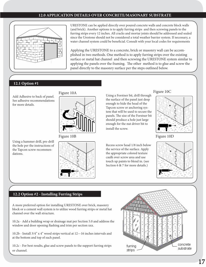
URESTONE can be applied directly over poured concrete walls and concrete block walls (and brick). Another options is to apply furring strips and then screwing panels to the furring strips every 12 inches. All cracks and mortar joints should be addressed and sealed since the Urestone should not be considered a total weather barrier system. If necessary, a water channel system could be beneficial. Consult with your local codes for requirements
Applying the URESTONE to a concrete, brick or masonry wall can be accom-plished in two methods. One method is to apply furring strips over the existing surface or metal hat channel and then screwing the URESTONE system similar to applying the panels over the framing. The other method is to glue and screw the panel directly to the masonry surface per the steps outlined below.
17
12.0 APPLICATION DETAILS OVER CONCRETE/MASONARY SUBSTRATE
Add Adhesive to back of panel. See adhesive recommendations for more details.
Using a Forstner bit, drill through the surface of the panel just deep enough to hide the head of the Tapcon screw or anchoring sys-tem that will be used to secure the panels. The size of the Forstner bit should produce a hole just large enough for the nut driver bit to install the screw.
Using a hammer drill, pre-drill the hole per the instructions of the Tapcon screw recommen-dations.
Recess screw head 1/8 inch below the service of the surface. Apply the appropriate colored texture caulk over screw area and use touch up paints to blend in. (see Section 6 & 7 for more details.)
Figure 10A
Figure 10B
Figure 10C
Figure 10D
12.1 Option #1
12.2 Option #2 - Installing Furring Strips
A more preferred option for installing URESTONE over brick, masonry block or a cement wall system is to utilize wood furring strips or metal hat channel over the wall structure. 10.2a - Add a building wrap or drainage mat per Section 5.0 and address the window and door opening flashing and trim per section xxx.
10.2b - Install 3/4” x 4” wood strips vertical at 12—16 inches intervals and at the bottom and top of each panel.
10.2c - For best results, glue and screw panels to the support furring strips or channel.

18
Post Framed Metal Building applications are different from Metal Buildings that have Metal Framing applications. The key dif-ference in installing a stone or brick wainscot on a Post Framing project,
POST FRAME BUILDINGS
Step 1- Apply a construction board such as OSB and proper framing to the intended wainscot height (24—48”).Step 2 - Apply a “J channel” or similar flashing at the wainscot height.Step 3 - Apply the metal siding to the top of the wainscot flashing.Step 4 - Apply the wainscot panel under the Flashing. Use the same installation details outlined in applying the URESTONE system over wood siding.
14.0 APPLICATIONS DETAILS FOR WOOD/METAL FRAME CONSTRUCTION
Figure 11A
There are a number of methods to apply URESTONE panels to metal siding applications. In metal framed building applications, where R-panel is typically used, the URESTONE panels can be applied over the siding profiles and we also have R-panel flashing for the gap between the metal building profile and the Urestone panel. In post frame / wood framed metal buildings, the metal siding is typically stopped 24-48” from the ground level and a construction board is used on this lower wainscot level. A “J Trim” is used as a flashing between the Metal build-ing siding and this lower wainscot area.The Urestone is then applied below this “J trim” and screwed into the OSB or similar material used for the wainscot area.
• See Section 3.0 for Water Barrier Application for recommended types of bar-riers.
13.0 METAL BUILDING CONSTRUCTION OVERVIEW

18
15.1 Application Over Metal Building “R-PANEL” Metal Siding
15.0 APPLICATION DETAILS OVER METAL BUILDING SIDINGThere are a number of application variations to apply the URESTONE in metal siding application depending if the project is a typical “Metal Building” (Steel Framing) or a “Post Framing” (Wood Framing) application . Below are some typical recommen-dations on each type.
REPLICATIONS UNLIMITED has designed flashing that fits the profile of an R-panel to fill in the gap between the metal siding and the URESTONE panel. (see figure 12A)
The first step to the installation is to apply the R-Panel flashing on the metal siding at the intended height on the building (typically the height of the URESTONE wainscot panels are between 36—42 inches and keep in mind this includes a built in top ledge. A lower height can be applied by cutting the bottom of these wainscot panel or you can use a 2ft 4ft panel along with separate top ledge for projects that need to be 24” to 38” high.
The next step is to apply a corner unit fol-lowed by the URESTONE wainscot panels. The panels are to be applied under the R-panel Trim that was previously applied to the build-ing. Self tapping metal screws should be used to attach the panels to the ribs of the R panel. (see figure 12C)
Attention should be given to the interlocking of the keys. It is important to screw the keys into solid support system so that warpage and separation does not occur. Sheet metal, metal hat channel or a cut R panels can be used to bridge the gap between ribs. (see figure 12D)
19
Figure 12A
Make sure all studs are straight and vertical and free of warped sections that would cause any undulations in the wall surface.Then properly fasten sheathing such OSB, plywood, Densglass sheeting or similar construction material to the framing according the local building codes or manu-facturer’s recommendation.Prior to applying the URESTONE system, a building wrap and water channel system should be used as the primary waterproofing system per the local building codes. URESTONE should not be considered a primary water tight and water-proofing system. See section- • See Section 3.0 for Water Barrier Application for recommended types of barriers.• See section 4.0 for Screw Recommendations for best methods of attaching the URESTONE system.
4.1 Wood / Metal Frame Construction
Figure 12B: installing flashing
METAL FRAME BUILDING

20
14.1 The URESTONE system can be applied to Modular Building structures. Many Modular building applications are installed on support piers or block above ground level (typically 2 ft) (see figure 14A) As a result, URESTONE wainscot system is a natural option to address this area. The installation method is to first install framing and ideally cover it with OSB on the gap under the modular building and the ground level (see figure 14B) The URESTONE panel should be glued and screwed to the building and screwed to the OSB/framing.
14.0 APPLICATION DETAILS ON MODULAR BUILDINGS
Figure 14A: Modular Building
Modular Buildings are typically placed on piers
Figure 14B: Framing Details
13.0 APPLICATION DETAILS ON EIFS STRUCTURES
Figure 13B: EIFS Building
URESTONE can be used in combination with an EIFS system (Exterior Insulation and Finish system) as a wainscot system for new or existing buildings. If the system is in good condition and has a proper drainage system built in, then the URESTONE system can be applied directly over the EFIS system. A Combination of screwing and gluing is recommended.
13.1 The URESTONE system can be applied over an existing EIFS exterior wall system. The EIFS system typically has 1—2 inches of an insulation board incorporated within the system, so it is important to make sure to use long enough screws to penetrate the Urestone panel and the insulation board so that the screw hits the plywood/OSB board of the EIFS System. It is recommended to use adhesive in addition to the screws.
Figure 13A: Typical EIFS Stepdown