Designing Water Waste Water
12
Updated: 04/24/09 Designing Water/Wastewater projects Using InRoads: Water/wastewater projects are typically replacement projects. The designer often times starts a design on a given microstation survey file. He will send out utility checks, condition checks, and research the area of the project for problems like easements, chemical spills, etc... The designer then proposed a solution by placing a proposed alignment on the survey. Usual Design Steps: Step 1 Make a copy of the survey file and save it as base.dgn. Step 2 Open the base.dgn file. Take note of the length of the project. Decide whether to design your project in a 20 or 40 scale. Step 3 Change the survey cells in base.dgn if they are not of the same standard as that required by your municipality you are designing to. If we are designing in a 40 scale and want to replace the cells of the trees, double click the cell tree in the cell library. Make sure that True Scale is clicked on the “Place Active Cell” box, input in 40 in the X Scale, Y Scale, and Z Scale boxes. Put the new trees on top of the cell trees done by the survey of Public Works. The new cells are automatically placed in the right levels (e.g., the trees are automatically placed in the level ‘Topography’). Make a new layer by clicking the “Level Manager” box. Name the new level “PW Tree” and turn that new level off. Go to the “Change Attribute” box and check only the level box and go to the level “PW Tree.” Click in all the old tree cells; they will become hidden and placed in the level “PW Tree.” Change the name of the levels that you are not going to use to “PW XXX” (e.g., Pntdesc to PW Pntdesc) and create new levels: Ex Street, Ex Water, and Ex Wastewater for the levels you are going to use. The idea here is to put all the useless data in the survey file to levels starting in PW and put most of the drawings (not all) in the survey file that we plan to use to levels starting in Ex. The additional appurtenances and proposed design will be put in levels starting with “Proposed” (e.g., Proposed water, Proposed wastewater, etc,) Here’s a sample level change: Cell: Water Meter PW Water Meter Cell: Valve PW Valve Cell: Tree PW Tree Traverse PW Traverse Text PW Text PNTNO PW PNTNO PNTDESC PW PNTDESC
Transcript of Designing Water Waste Water
8/8/2019 Designing Water Waste Water
http://slidepdf.com/reader/full/designing-water-waste-water 1/12
Updated: 04/24/09
Designing Water/Wastewater projects Using InRoads:
Water/wastewater projects are typically replacement projects. The designer oftentimes starts a design on a given microstation survey file. He will send out utility checks,condition checks, and research the area of the project for problems like easements,chemical spills, etc... The designer then proposed a solution by placing a proposedalignment on the survey.
Usual Design Steps:
Step 1Make a copy of the survey file and save it as base.dgn.
Step 2Open the base.dgn file. Take note of the length of the project. Decide whether to
design your project in a 20 or 40 scale.
Step 3Change the survey cells in base.dgn if they are not of the same standard as that
required by your municipality you are designing to. If we are designing in a 40 scale andwant to replace the cells of the trees, double click the cell tree in the cell library. Makesure that True Scale is clicked on the “Place Active Cell” box, input in 40 in the X Scale,Y Scale, and Z Scale boxes. Put the new trees on top of the cell trees done by the surveyof Public Works. The new cells are automatically placed in the right levels (e.g., the treesare automatically placed in the level ‘Topography’). Make a new layer by clicking the“Level Manager” box. Name the new level “PW Tree” and turn that new level off. Go tothe “Change Attribute” box and check only the level box and go to the level “PW Tree.”Click in all the old tree cells; they will become hidden and placed in the level “PW Tree.”
Change the name of the levels that you are not going to use to “PW XXX” (e.g.,Pntdesc to PW Pntdesc) and create new levels: Ex Street, Ex Water, and Ex Wastewaterfor the levels you are going to use. The idea here is to put all the useless data in thesurvey file to levels starting in PW and put most of the drawings (not all) in the surveyfile that we plan to use to levels starting in Ex. The additional appurtenances andproposed design will be put in levels starting with “Proposed” (e.g., Proposed water,Proposed wastewater, etc,)
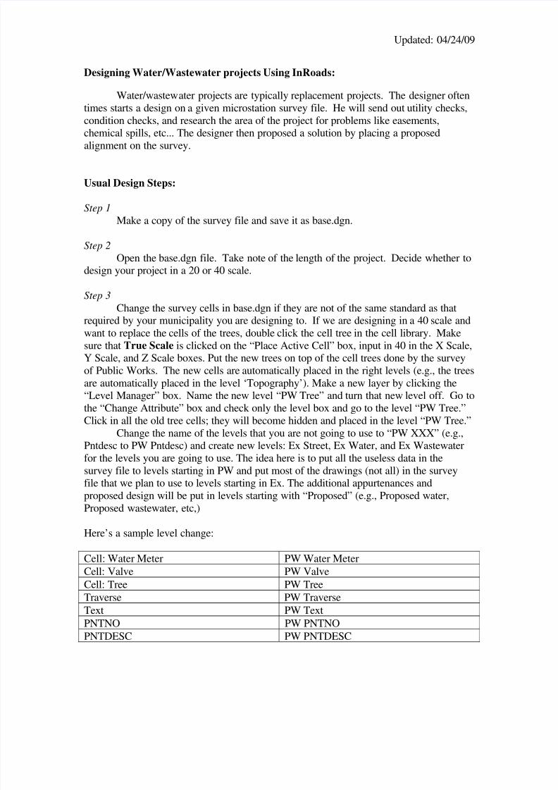
Here’s a sample level change:
Cell: Water Meter PW Water MeterCell: Valve PW ValveCell: Tree PW TreeTraverse PW TraverseText PW TextPNTNO PW PNTNOPNTDESC PW PNTDESC
8/8/2019 Designing Water Waste Water
http://slidepdf.com/reader/full/designing-water-waste-water 2/12
Updated: 04/24/09
NODE PW NODECell: IR PW IRMiscellaneous PW DATALINES: Contour PW ContourLINES: Center PW CENTER
LINES: Ex. Water Ex. WaterLINES: Ex. Wastewater Ex. WastewaterLINES: STREET Ex StreetDRAWING: CONCRETE Ex ConcreteCell: VB (Valve Box) PW VB
Useful Data for Drawing:
For Water mains:
Existing Water Mainand Appurtenances
Level Weight Style or LC (LineCode)
Color (CO)
30” & Larger Mains(See 4.04)
Ex Water 0 0 1
8”to 27” Mains Ex Water 1 0 16” Main Ex Water 1 3 14” Main Ex Water 1 2 1
For Wastewater mains:
Existing WastewaterMain andAppurtenances
Level Weight Style or LC(Line Code)
Color (CO)
30” & Larger Mains(See 4.06)
Ex Wastewater 1 0 6
6” to 27” Mains Ex Wastewater 1 0 6Laterals Ex Wastewater 0 0 6
For Proposed Water:
Proposed WaterMains
Level Weight Style or LC(Line Code)
Color (CO)
30” & LargerMains (See4.05)
Proposed Water 3 0 2
8” to 27” Mains Proposed Water 4 0 26” Main Proposed Water 4 3 2
8/8/2019 Designing Water Waste Water
http://slidepdf.com/reader/full/designing-water-waste-water 3/12
Updated: 04/24/09
4” Main Proposed Water 4 2 2
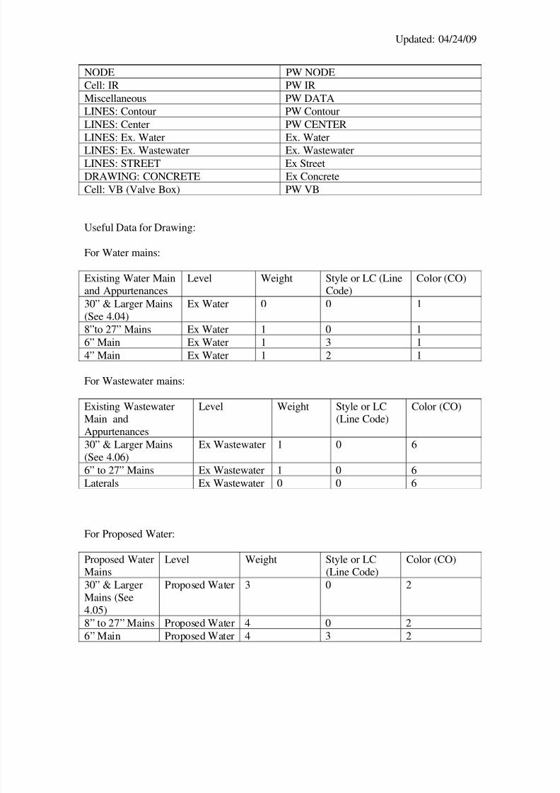
The picture below has the levels of the existing water, wastewater, and street turned on:
Step 4Design a solution (e.g., draw your proposed water/wastewater pipes/manholes in
base.dgn). Choose the locations of the match mark cuts for the design sheets. Draw thedistances of your proposed water/wastewater line from the property lines and existingwater/wastewater mains. Also note that the cuts should be in the multiples of 50’.
8/8/2019 Designing Water Waste Water
http://slidepdf.com/reader/full/designing-water-waste-water 4/12
Updated: 04/24/09
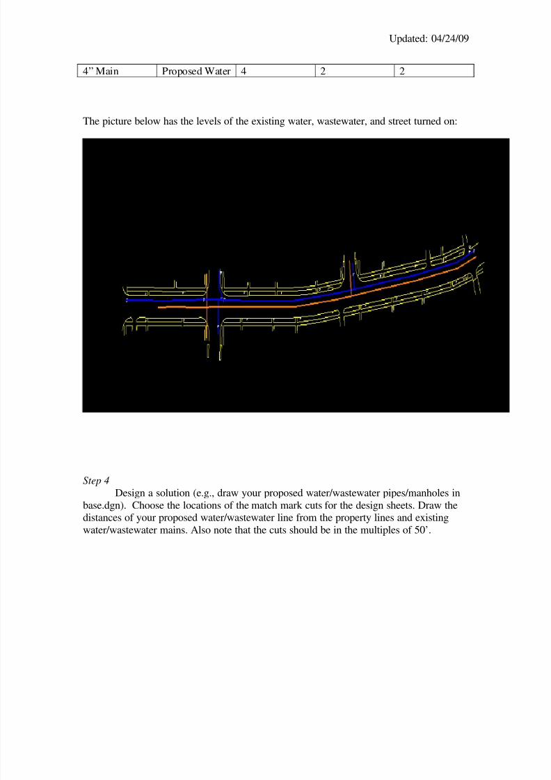
Below is a sample design proposal for the location of the replacement water main:
The Green line (thickest line) shows the location of the proposed water mainreplacement.
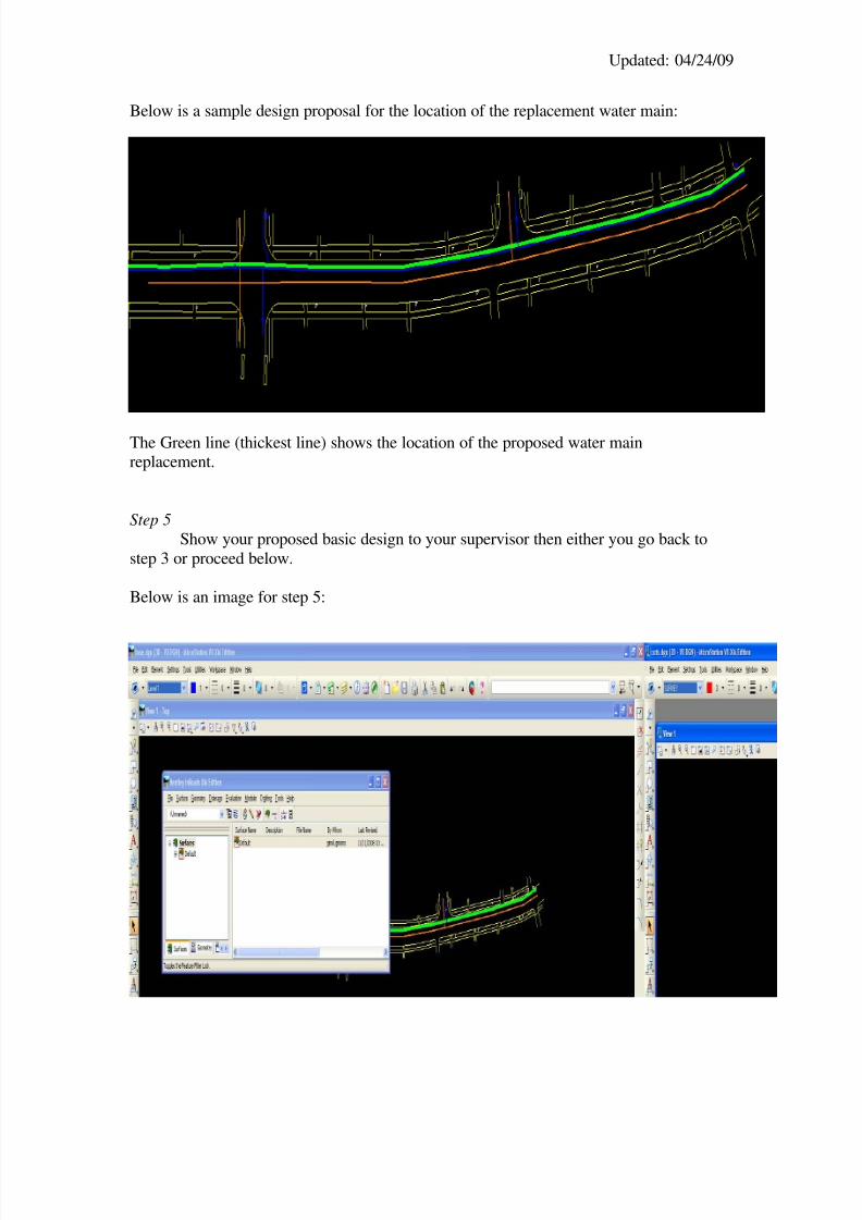
Step 5Show your proposed basic design to your supervisor then either you go back to
step 3 or proceed below.
Below is an image for step 5:
8/8/2019 Designing Water Waste Water
http://slidepdf.com/reader/full/designing-water-waste-water 5/12
Updated: 04/24/09
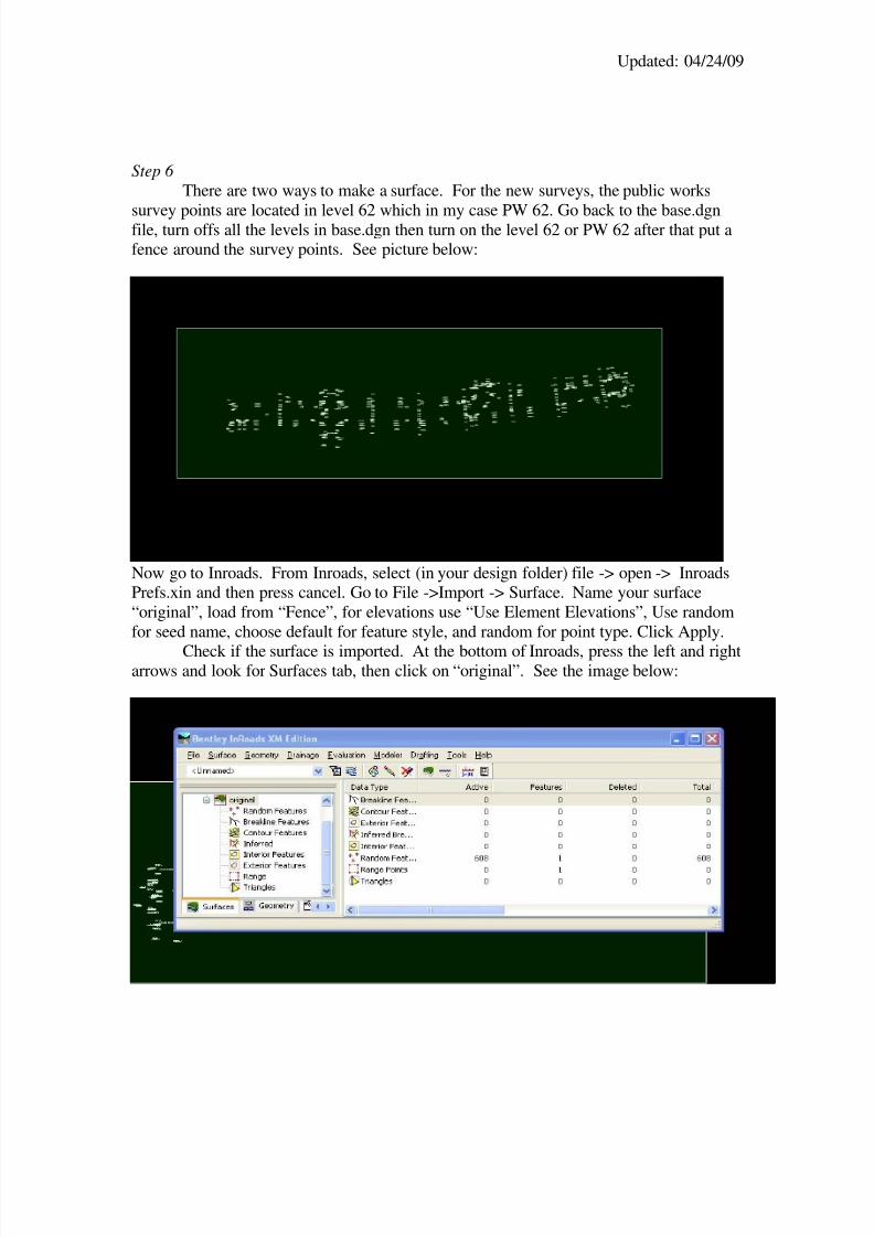
Step 6 There are two ways to make a surface. For the new surveys, the public works
survey points are located in level 62 which in my case PW 62. Go back to the base.dgnfile, turn offs all the levels in base.dgn then turn on the level 62 or PW 62 after that put afence around the survey points. See picture below:
Now go to Inroads. From Inroads, select (in your design folder) file -> open -> InroadsPrefs.xin and then press cancel. Go to File ->Import -> Surface. Name your surface“original”, load from “Fence”, for elevations use “Use Element Elevations”, Use randomfor seed name, choose default for feature style, and random for point type. Click Apply.
Check if the surface is imported. At the bottom of Inroads, press the left and rightarrows and look for Surfaces tab, then click on “original”. See the image below:
8/8/2019 Designing Water Waste Water
http://slidepdf.com/reader/full/designing-water-waste-water 6/12
Updated: 04/24/09
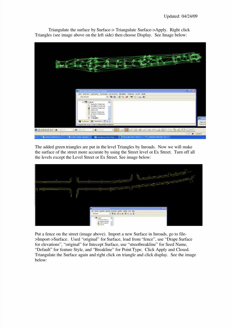
Triangulate the surface by Surface-> Triangulate Surface->Apply. Right click Triangles (see image above on the left side) then choose Display. See Image below:
The added green triangles are put in the level Triangles by Inroads. Now we will makethe surface of the street more accurate by using the Street level or Ex Street. Turn off allthe levels except the Level Street or Ex Street. See image below:
Put a fence on the street (image above). Import a new Surface in Inroads, go to file->Import->Surface. Used “original” for Surface, load from “fence”, use “Drape Surfacefor elevations”, “original” for Intecept Surface, use “streetbreakline” for Seed Name,“Default” for feature Style, and “Breakline” for Point Type. Click Apply and Closed.Triangulate the Surface again and right click on triangle and click display. See the imagebelow:
8/8/2019 Designing Water Waste Water
http://slidepdf.com/reader/full/designing-water-waste-water 7/12
Updated: 04/24/09
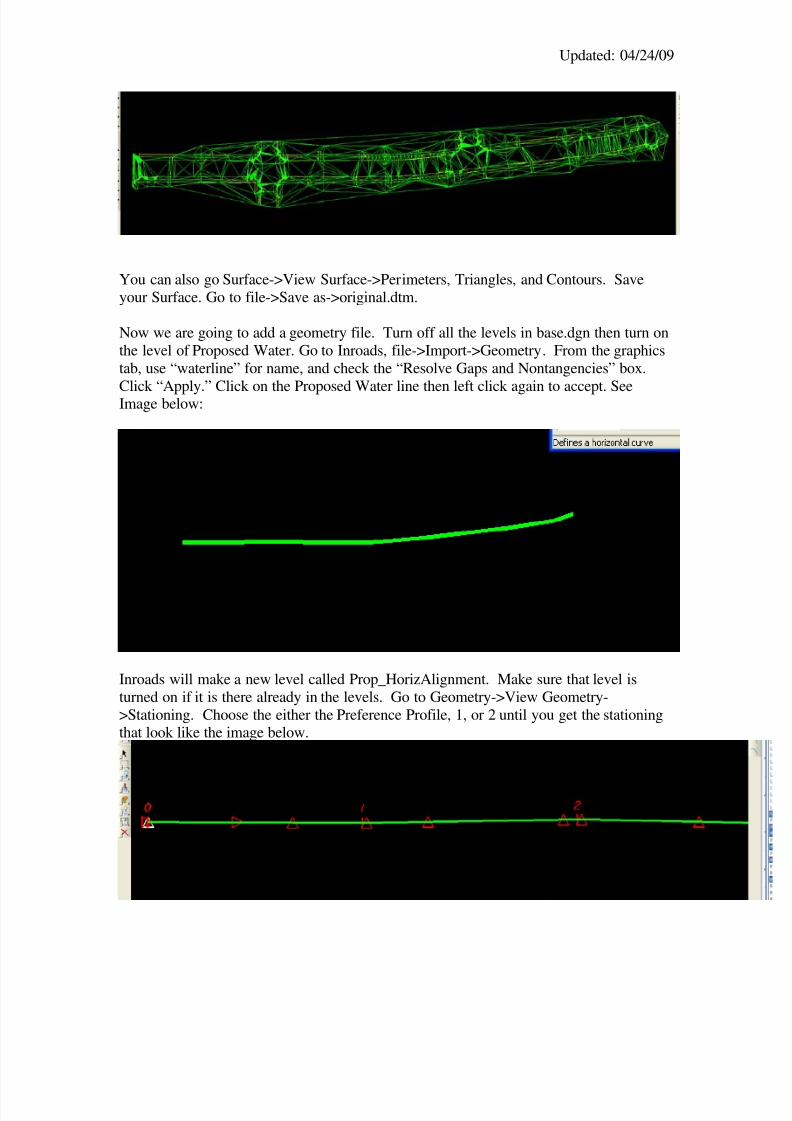
You can also go Surface->View Surface->Perimeters, Triangles, and Contours. Saveyour Surface. Go to file->Save as->original.dtm.
Now we are going to add a geometry file. Turn off all the levels in base.dgn then turn onthe level of Proposed Water. Go to Inroads, file->Import->Geometry. From the graphicstab, use “waterline” for name, and check the “Resolve Gaps and Nontangencies” box.
Click “Apply.” Click on the Proposed Water line then left click again to accept. SeeImage below:
Inroads will make a new level called Prop_HorizAlignment. Make sure that level isturned on if it is there already in the levels. Go to Geometry->View Geometry->Stationing. Choose the either the Preference Profile, 1, or 2 until you get the stationingthat look like the image below.
8/8/2019 Designing Water Waste Water
http://slidepdf.com/reader/full/designing-water-waste-water 8/12
Updated: 04/24/09
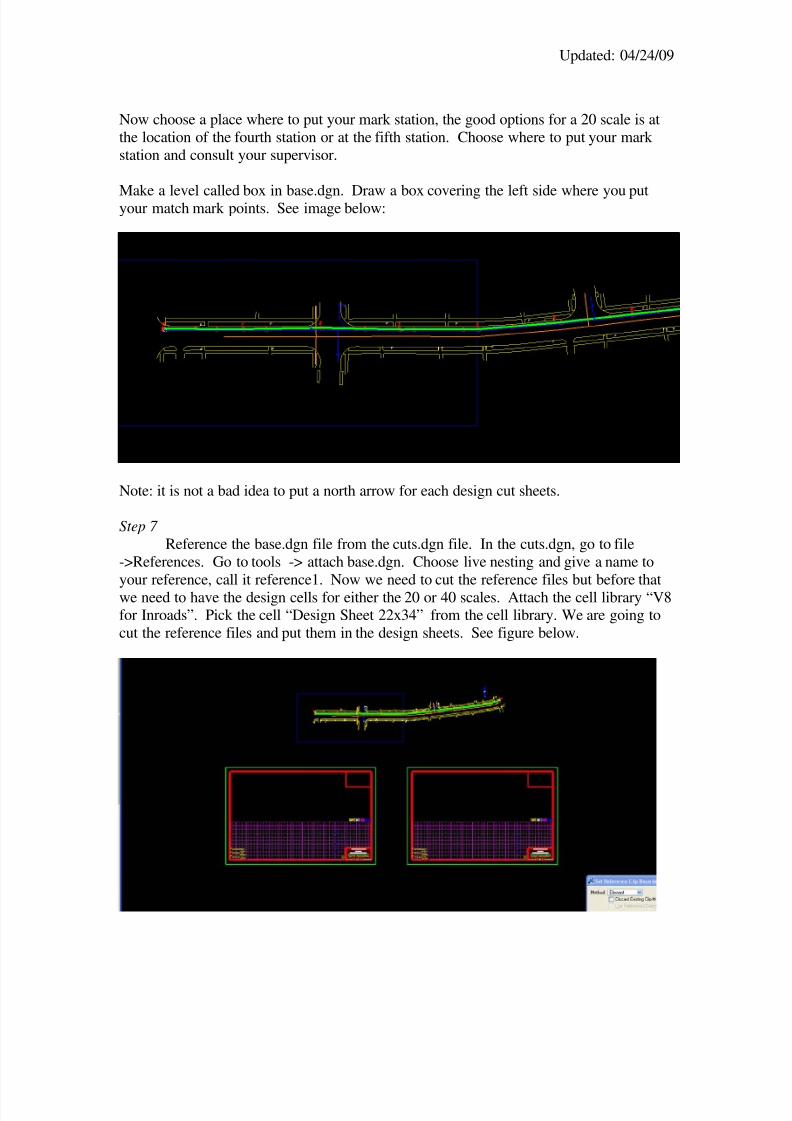
Now choose a place where to put your mark station, the good options for a 20 scale is atthe location of the fourth station or at the fifth station. Choose where to put your mark station and consult your supervisor.
Make a level called box in base.dgn. Draw a box covering the left side where you putyour match mark points. See image below:
Note: it is not a bad idea to put a north arrow for each design cut sheets.
Step 7 Reference the base.dgn file from the cuts.dgn file. In the cuts.dgn, go to file
->References. Go to tools -> attach base.dgn. Choose live nesting and give a name toyour reference, call it reference1. Now we need to cut the reference files but before thatwe need to have the design cells for either the 20 or 40 scales. Attach the cell library “V8for Inroads”. Pick the cell “Design Sheet 22x34” from the cell library. We are going tocut the reference files and put them in the design sheets. See figure below.
8/8/2019 Designing Water Waste Water
http://slidepdf.com/reader/full/designing-water-waste-water 9/12
Updated: 04/24/09
Step 8Make a surface profile out of your waterline geometry. In Inroads, Click
Evaluation -> Profile -> Create Profile then go to the preferences tab select profile, click load then close. As of this writing the preferences are set in the 40 scale but if you aredesigning in the 20 scale you need to change 6.6666 to 3.3333 in the exaggeration box.
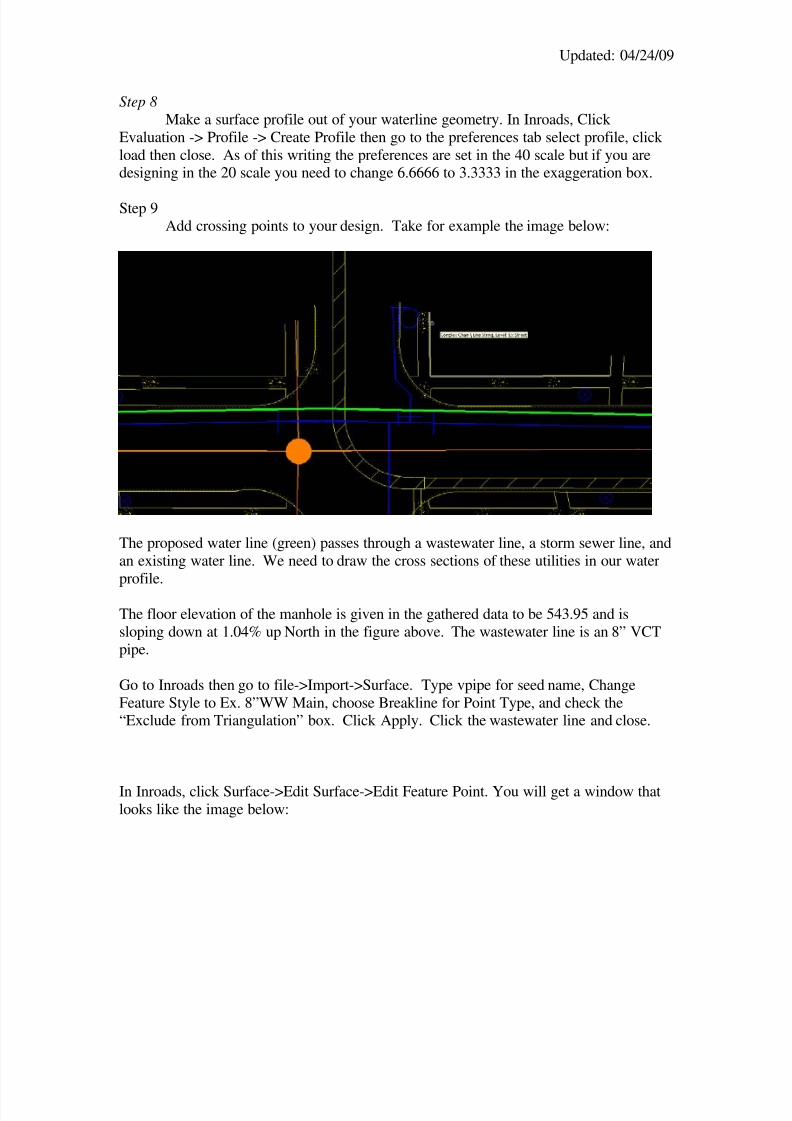
Step 9Add crossing points to your design. Take for example the image below:
The proposed water line (green) passes through a wastewater line, a storm sewer line, andan existing water line. We need to draw the cross sections of these utilities in our waterprofile.
The floor elevation of the manhole is given in the gathered data to be 543.95 and issloping down at 1.04% up North in the figure above. The wastewater line is an 8” VCTpipe.
Go to Inroads then go to file->Import->Surface. Type vpipe for seed name, ChangeFeature Style to Ex. 8”WW Main, choose Breakline for Point Type, and check the“Exclude from Triangulation” box. Click Apply. Click the wastewater line and close.
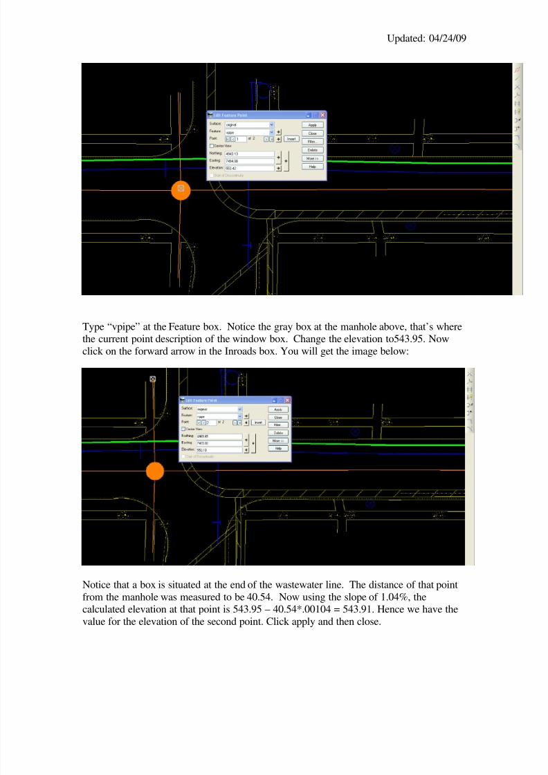
In Inroads, click Surface->Edit Surface->Edit Feature Point. You will get a window thatlooks like the image below:
8/8/2019 Designing Water Waste Water
http://slidepdf.com/reader/full/designing-water-waste-water 10/12
Updated: 04/24/09
Type “vpipe” at the Feature box. Notice the gray box at the manhole above, that’s wherethe current point description of the window box. Change the elevation to543.95. Nowclick on the forward arrow in the Inroads box. You will get the image below:
Notice that a box is situated at the end of the wastewater line. The distance of that pointfrom the manhole was measured to be 40.54. Now using the slope of 1.04%, thecalculated elevation at that point is 543.95 – 40.54*.00104 = 543.91. Hence we have thevalue for the elevation of the second point. Click apply and then close.
8/8/2019 Designing Water Waste Water
http://slidepdf.com/reader/full/designing-water-waste-water 11/12
Updated: 04/24/09
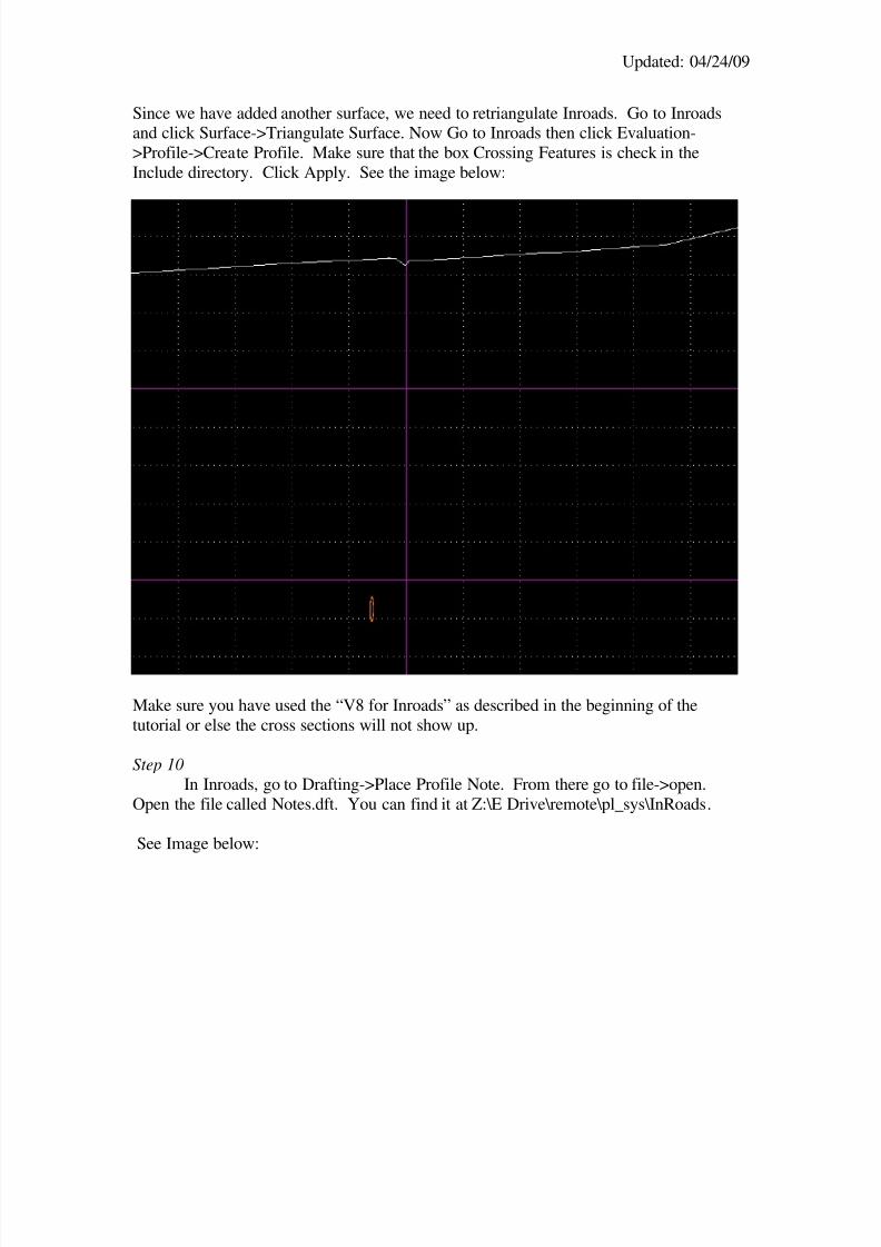
Since we have added another surface, we need to retriangulate Inroads. Go to Inroadsand click Surface->Triangulate Surface. Now Go to Inroads then click Evaluation->Profile->Create Profile. Make sure that the box Crossing Features is check in theInclude directory. Click Apply. See the image below:
Make sure you have used the “V8 for Inroads” as described in the beginning of thetutorial or else the cross sections will not show up.
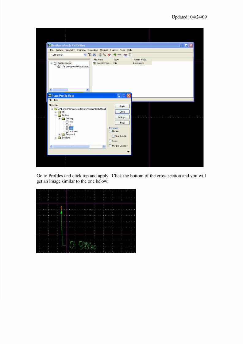
Step 10In Inroads, go to Drafting->Place Profile Note. From there go to file->open.
Open the file called Notes.dft. You can find it at Z:\E Drive\remote\pl_sys\InRoads.
See Image below:
8/8/2019 Designing Water Waste Water
http://slidepdf.com/reader/full/designing-water-waste-water 12/12
Updated: 04/24/09
Go to Profiles and click top and apply. Click the bottom of the cross section and you willget an image similar to the one below: