Designing SLIDES - Farnell · 2013-08-20 · Accuride provides several lengths of brackets to meet...
20
An overview of electronic enclosure construction and components SLIDES Electronic Enclosures Designing into
Transcript of Designing SLIDES - Farnell · 2013-08-20 · Accuride provides several lengths of brackets to meet...
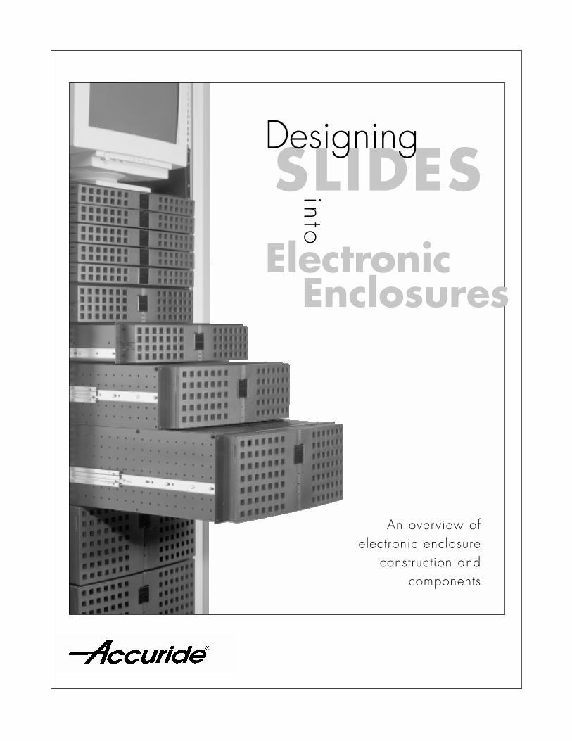
An overview of electronic enclosure
construction and components
SLIDESElectronic
Enclosures
Designing
into

Table of Contents
Cabinets and Rails 1
Cabinet Rail Construction 3
Chassis 5
Slide Selection Criteria 6
Bracket-to-Rail Mounting 8
Calculating Overall Slide and Bracket Thickness 9
Slide Position on the Chassis 11
Locating/Transferring the Slide Hole Pattern to the Chassis 13
Component Assembly 14
Bracket and Bar Nut Comparisons 15
Glossary 16
SLIDESElectronic
Enclosures
Designing
into

DESIGNING SLIDES INTO ELECTRONIC ENCLOSURES
1
There are two main aspects to consider when designing slides into electronic
enclosures: the cabinet construction and the chassis (or drawer). The attributes
of these components affect the overall enclosure configuration and the
selection of slides, brackets and cable carriers.
Chassis
MountingRail
ChassisFront
Slide
RightSide
CabinetTop
Rear
Depth
Basic Cabinet Construction
Cabinets vary according to
manufacturer and the intended
use of the cabinet. Each manu-
facturer may have unique rail
thicknesses, shapes, materials
and placement. Since the
slides mount to the cabinet rails
and the chassis mounts to the
slide, the variances in construc-
tion have a significant affect on
the enclosure design.
CABINETS & RAILS

2
Top
LeftSide
Rear RightSide
Front
MountingRail
17.72"[450 mm]
Cabinet Construction
Most electronic cabinets/enclosuresare based on dimensional guidelinesas illustrated in the ANSI/EIA 310Specifications.
❍ A standard 17.72” [450 mm]opening is the minimum widthbetween the rails.
❍ Rails carry a repetitive pitch pattern of mounting holes.
❍ 1.75” [44.45 mm] or “1U”is the universal spacing increment and nominal height for drawers.
Basic EIA cabinet construction details
❍ Cabinets contain four or more rails (columns, uprights or struts). The enclosure may or may not have a surrounding skin
❍ There are front rails, rear rails, andoptional mid-rails
❍ Rail mounting patterns are based on standard EIA specifications
❍ There is no limitation onoverall cabinet height.
FRACTIONINCH
DECIMALINCH
METRIC (MM)
EIA MOUNTINGPATTERN
15.8715.8712.7015.8715.8712.7015.8715.8712.70
.625
.625
.500
.625
.625
.500
.625
.625
.500
58
58
581.75 (1U)
(2U)
1.75 (1U)
58
58
58
12
12
12
ANSI/EIA 310 Specifications

3
DepthRail to Rail
Rear
Front RH
LH
MinimumRail to Rail
MaximumRail to Rail
Front
LH
RH
Rear
Mid-RailDistance
DepthRail to Rail
RH
Front
LH
Rear
NormallyAdjustable
Generally FixedNon-adjustable
❍ Non-Adjustable Rails
Cabinet construction that provides a set distance from front rail to rear rail.
❍ Adjustable Rails
Cabinet contruction that allows the end-user to relocate either front and/or rear rails to an alternate distance from front to rear.
❍ Mid Rails
Cabinet is constructed with an additional set of rails, either adjustable or fixed to provide an alternate mounting distance to accommodate both short and deep slide lengths or various chassis depths.
Non-Adjustable Rails
Adjustable Rails
Mid Rails
Generally, cabinet rail construction methodsfall into the following groups:
CABINET RAIL CONSTRUCTION
4
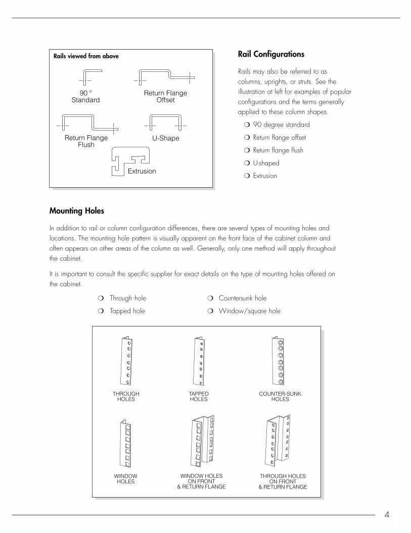
Rail Configurations
Rails may also be referred to ascolumns, uprights, or struts. See the illustration at left for examples of popularconfigurations and the terms generallyapplied to these column shapes.
❍ 90 degree standard
❍ Return flange offset
❍ Return flange flush
❍ U-shaped
❍ Extrusion
Return FlangeOffset
Return FlangeFlush
90 ºStandard
Extrusion
U-Shape
Mounting Holes
In addition to rail or column configuration differences, there are several types of mounting holes andlocations. The mounting hole pattern is visually apparent on the front face of the cabinet column and often appears on other areas of the column as well. Generally, only one method will apply throughoutthe cabinet.
It is important to consult the specific supplier for exact details on the type of mounting holes offered on the cabinet.
❍ Through hole ❍ Countersunk hole
❍ Tapped hole ❍ Window/square hole
THROUGHHOLES
TAPPEDHOLES
COUNTER-SUNKHOLES
WINDOWHOLES
WINDOW HOLESON FRONT
& RETURN FLANGE
THROUGH HOLESON FRONT
& RETURN FLANGE
Rails viewed from above

5
Chassis is the term for an electronicdrawer. The height of a chassis isbased on a nominal EIA unit incre-ment of 1.75” [44.45 mm].
Each increment is referred to as a“U”. The minimum measure of a chassis is 1U, with subsequent measures expressed as follows:2U (3.50”) [88.90 mm], 3U (5.25”)[133.35 mm], etc.
ChassisFront
Unit
Depth Top
RightSide
Rear
The actual height differs from the nominal height. See the chart below for specific measures.
Definition of units
EIA Unit Nominal Height Maximum Actual Height
IU 1.75” [44.45 mm] 1.72” [43.69 mm]
2U 3.50” [88.90 mm] 3.47” [88.14 mm]
3U 5.25” [133.35 mm] 5.22” [132.59 mm]
4U 7.00” [177.80 mm] 6.97” [177.04 mm]
N (number of) Units N Units x 1.75” [44.45 mm] N Units x 1.75” [44.45 mm] - .03” [.8 mm]
CHASSIS

6
3 SECTIONSLIDE
SlideLengthSlide
Length
Travel = Slide Length (minimum)
Travel = 3/4 Slide Length
2 SECTIONSLIDE
SLIDE SELECTION CRITERIA
Selecting the correct Accuride slides and bracketry is based on the following criteria:
❍ Height of drawer ❍ Mounting rail-to-rail distance
❍ Anticipated chassis load ❍ Slide to cabinet mounting bracketry
❍ Amount of chassis travel ❍ Accessories on slide (locking, disconnect, hole pattern)
❍ Overall depth of cabinet
Anticipated chassis loadIdentifying the chassis load will narrow the range of slide models suitable to the application.
Slide load ratings are based on dynamic loading, which is continuous motion both out and into the cabinet.
❍ Load ratings for slides in electronic enclosure applications are based on 2,000 cycles
❍ One cycle is considered the distance from fully closed to fully opened to fully closed in one motion.
❍ The cycle speed is generally based on 10–12 cycles per minute.
All Accuride slides accept a static overload of 2 times the indicated load rating as a margin of safetywhen the slide is fully extended.
Consult Accuride for additional test information for shock and vibration, momentary, seismic, or other special requirements.
Amount of chassis travelDetermining the distance the chassis will be required to travel (the relationship between the back of thechassis and the front of the cabinet) will help establish whether a two- or three-section slide is best suitedfor a particular application.
Two-section slides provide 3/4 travel. In other words, the drawer opens approximately three-quarters ofthe total slide length.
Three-section slides offer full extension or over travel; the drawer opens the same amount or more thanthe length of the slide.
7
Rail to RailDistance (Depth)
OVERALLCABINET DEPTH
Bracket toBracket Distance
SlideLength
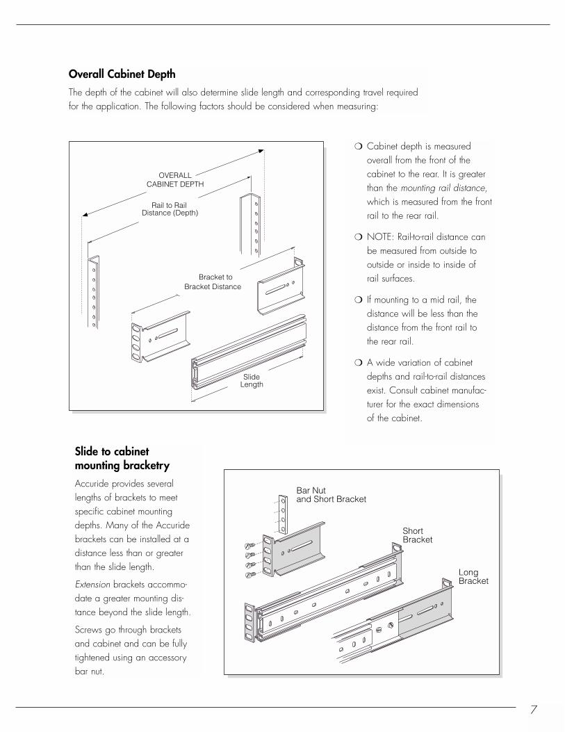
Overall Cabinet DepthThe depth of the cabinet will also determine slide length and corresponding travel requiredfor the application. The following factors should be considered when measuring:
❍ Cabinet depth is measured overall from the front of the cabinet to the rear. It is greater than the mounting rail distance, which is measured from the front rail to the rear rail.
❍ NOTE: Rail-to-rail distance canbe measured from outside tooutside or inside to inside ofrail surfaces.
❍ If mounting to a mid rail, thedistance will be less than the distance from the front rail tothe rear rail.
❍ A wide variation of cabinet depths and rail-to-rail distances exist. Consult cabinet manufac-turer for the exact dimensions of the cabinet.
ShortBracket
Bar Nut and Short Bracket
LongBracket
Slide to cabinet mounting bracketryAccuride provides severallengths of brackets to meet specific cabinet mountingdepths. Many of the Accuridebrackets can be installed at adistance less than or greaterthan the slide length.
Extension brackets accommo-date a greater mounting dis-tance beyond the slide length.
Screws go through brackets and cabinet and can be fullytightened using an accessory bar nut.
8
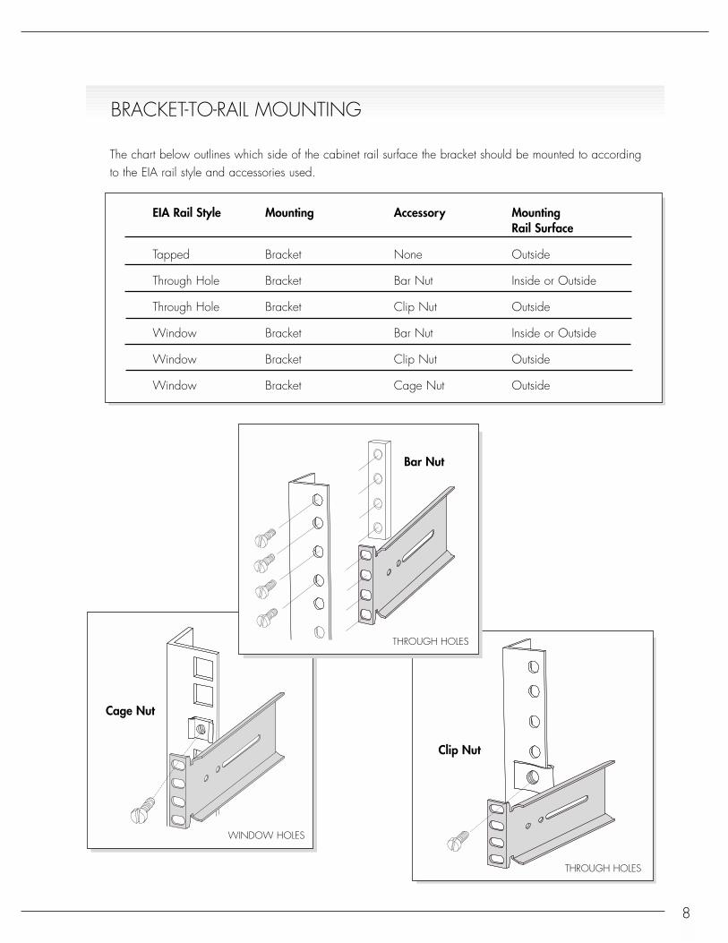
The chart below outlines which side of the cabinet rail surface the bracket should be mounted to according to the EIA rail style and accessories used.
EIA Rail Style Mounting Accessory MountingRail Surface
Tapped Bracket None Outside
Through Hole Bracket Bar Nut Inside or Outside
Through Hole Bracket Clip Nut Outside
Window Bracket Bar Nut Inside or Outside
Window Bracket Clip Nut Outside
Window Bracket Cage Nut Outside
BRACKET-TO-RAIL MOUNTING
Bar Nut
Cage Nut
Clip Nut
THROUGH HOLES
THROUGH HOLES
WINDOW HOLES
9
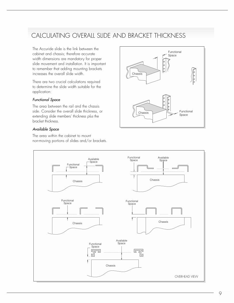
The Accuride slide is the link between the cabinet and chassis; therefore accurate width dimensions are mandatory for properslide movement and installation. It is importantto remember that adding mounting bracketsincreases the overall slide width.
There are two crucial calculations required to determine the slide width suitable for the application:
Functional Space
The area between the rail and the chassisside. Consider the overall slide thickness, orextending slide members’ thickness plus thebracket thickness.
Available Space
The area within the cabinet to mount non-moving portions of slides and/or brackets.
FunctionalSpace
FunctionalSpace
Chassis
Chassis
AvailableSpace
AvailableSpace
FunctionalSpace
FunctionalSpace
FunctionalSpace
FunctionalSpace
Chassis
Chassis
Chassis
Chassis
Chassis
FunctionalSpace
AvailableSpace
CALCULATING OVERALL SLIDE AND BRACKET THICKNESS
OVERHEAD VIEW

10
The drawings at left show several mounting configurations from an overhead perspective. This viewpoint demonstrates how chassis widthsare calculated; slide thickness evaluated, andinstallations of brackets verified.
❍ Bracket behind rail
❍ Bracket in front of rail
❍ Recessed bracket behind rail
❍ Bracket behind flush-return rail
❍ Recessed slide and bracket behind rail
If some component dimensions are known, thespace available for the remaining componentsmay be determined:
IF KNOWN CAN BE DETERMINED
Slide width Chassis width and cabinet opening
Chassis width Slide width/and cabinet opening bracket thickness
Cabinet opening Chassis width andslide width
CabinetOpening
Slide Thickness ChassisWidth
CabinetOpening
ChassisWidth
Slide Thickness +Bracket Thickness
CabinetOpening
ChassisWidth
Slide Thickness +Bracket Thickness
(Ref.)
Functional Space
CabinetOpening
ChassisWidth
Slide Thickness +Bracket Thickness
CabinetOpening
ChassisWidth
Functional Space
Bracket behind rail
Bracket in front of rail
Recessed bracket behind rail
Bracket behind flush-return rail
Recessed slide & bracket behind rail

11
There are a number of factors used to determine the optimal slide-to-chassis mounting position:
❍ The internal components (venting, fans, plugs, screws, etc.) inside the chassis must be taken into account when establishing slide mounting position.
❍ The chassis center of gravity dictates location. The slide should be closelyassociated with the center of gravity to ensure chassis stability and slide performance.
❍ The chassis manufacturer may have a pre-designated mounting location.
L
LOW MIDDLE UPPER
Slide C
UNIT
UNIT
FrontBezel
Chassis
UNIT
UNIT
EIA cabinet pitch❍ Consider the overall U height by using the bottom of
the chassis as a reference and including the front panel or bezel which may have a greater height thanthe actual chassis.
❍ Make sure the slide/bracket location aligns with EIA cabinet pattern.
❍ Slide height should not exceed specific unit height.
SLIDE POSITION ON THE CHASSIS
EIA Mounting Pattern
UNITS
2U
1.75" (1U)
1.75" (1U)
58
58
58
58
58
58
12
12
12
12
Bracket alignment to EIA cabinet determines slide
Bottom of chassis (unit)
Slide determines hole pattern on chassis
LC
LC
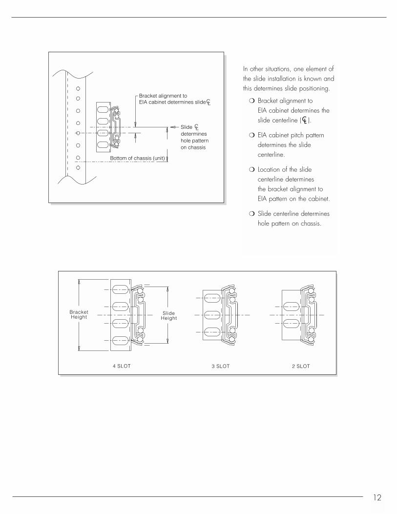
In other situations, one element ofthe slide installation is known andthis determines slide positioning.
❍ Bracket alignment to EIA cabinet determines the slide centerline ( ).
❍ EIA cabinet pitch pattern determines the slide centerline.
❍ Location of the slide centerline determines the bracket alignment to EIA pattern on the cabinet.
❍ Slide centerline determineshole pattern on chassis.
BracketHeight
SlideHeight
4 SLOT 3 SLOT 2 SLOT
CL

13
The following illustrations assume the chassis front panel contacts thecabinet structure. Slide bracket placement and use of hardware willdetermine exact dimensions.
Determining the hole pattern from slide to chassis is calculated whenthe slide is fully closed or when the chassisis in its final closed position. The use ofhardware with or without washers plays animportant role in determining the fullyclosed position of the chassis relative to the cabinet’s front rails. If washers are used, be
sure to include the washer thickness dimension in your overall distancewhen determining the first chassis hole location.
Follow the guideline that matches your planned installation to obtainfirst chassis hole dimension. Refer to Accuride data sheets to obtainremaining mounting hole locations.
First Holeon ChassisDistance
to first holeon slide
LOC
Fixed or Outer Slide Member
Moving or InnerSlide Member
LOC
RAIL
BRACKET
SLIDE
CHASSIS
LOC
LOC
LOC
LOC
.19
.45
FRONT PANEL
Measurementto first hole on slide
Measurementto first hole on slide
Measurementto first hole on slide
Measurementto first hole on slide
Measurementto first hole on slide
A
B
C
D
E
Bracket behind or in front of railScrew contacts back of chassis front panel (fig. A)Front panel thickness + screw head thickness + cabinet rail thickness+ distance to first slide mounting hole location
When using a flat head screw or other flush type (fig. B)Front panel thickness + cabinet rail thickness + distance to first slide mounting hole location
Bracket in front of rail, slide and bracket aligned (fig. C) Front panel thickness + screw head thickness + distance to first slide mounting hole location
Bracket in front or behind rail with recessed bracketsRecessed style bracket in front of rail (fig. D)Front panel thickness + screw head thickness + .45” [11.43 mm] + distance to first slide mounting hole location
Screw head contacts front panel, bracket is recessed behind rail (fig. E)Front panel thickness + screw head thickness + cabinet rail thickness + .19” [4.83 mm] + distance to first slide mounting hole location
LOCATING/TRANSFERRING SLIDE HOLE PATTERN TO CHASSIS
Washer
Screw Head
Overall Thickness

14
Mounting AccessoriesTypical hardware for EIA packaging is shown. Due to differences in cabinetconstruction, not all hardware styles are shown.
KepsScrew
Hex Nut
Bar Nut
Pan HeadScrew
Flat HeadScrew
Self-LockingNut
ClipNut
TinnermanClip
ToothWasher
PanelWasher
LockWasher
FlatWasher
CageNut
Socket HeadScrew
TorxHead
LOC
Cabinet
Slide to Chassismounting hole pattern
Screw
Chassis
Slide
Bracket
Bracket
Bar Nut
Washer
Screw HeadThickness
Overall Thickness
Screw Head Height
Screw Head Thickness
LOC = Distance to location of first hole on slide. Slide is fully closed.
COMPONENT ASSEMBLY

15
2.50
5/8
1/2
5/8
1.635/8
5/81.63 1-1/4 1.88
5/8
1/21/21.50 1.25 5/8
2.50 1.881.63
1.50 1.25
Accuride provides several mounting brackets and bar nut accessories to meet specific locations on theEIA cabinet. The use of 4-slot, 3-slot, and 2-slot mounting brackets and the companion bar nut selectionprovide a wide range of mounting possibilities. Consult Accuride data sheets for dimensions.
LSlide C LSlide CLSlide C
4 SLOT 3 SLOT 2 SLOT
BracketHeight
SlideHeight
4 SLOT 3 SLOT 2 SLOT
BRACKET AND BAR NUT COMPARISONS
Bar Nuts

Cabinet WidthThe outside dimension (side to side) of a cabinet orenclosure.
Panel WidthThe outer dimension of the front mounting rails whichis greater than the clear opening between rails.
Cable CarrierAn accessory item to support and manage wiringbehind a chassis when it is withdrawn or insertedinto the cabinet.
Clear OpeningThe innermost dimensionbetween the front mountingrails.
Chassis Front PanelAlso known as panel width.Generally greater than thechassis width.
DepthThe front to rear dimensionsof a cabinet or enclosure.
ChassisA universal term for an elec-tronics drawer; also known as the unit, drawer, module, device, stack equipment, system.
Front Panel or BezelThe front facade of the chassis.
Front Panel ThicknessDistance from front of cabinet rail to front end of chassis.
Cabinet Rail UprightAlso known as mounting rail, column, strut, upright.
16
GLOSSARY:
CabinetWidth
Depth
PanelWidth
ClearOpening
Clear Opening
VIEWED FROM ABOVE
Chassis Width
Spacefor Slides
Spacefor Slides
Rail to Rail
ChassisFront
Unit
Depth Top
RightSide
Rear

17
GLOSSARY:
Cabinet Mounting ScrewsElectronic hardware that attaches the slide brackets tothe rails.
SlideSliding mechanism that serves as link betweenthe enclosure and chassis. Also known as rail,glide, track, runner, chassis member, suspension.
Slide Mounting BracketAttachment device between the slide and cabinet.
Bar NutThreaded accessory used in place of hex nutsand washers.
LocThe distance to the first mounting hole availableon the moving or inner slide member.
– The slide centerline
U (unit)Incremental measure of 1.75” [44.45 mm].
Universal Cabinet PatternMounting holes on cabinet rails in a repetitiveseries as follows:1/2”, 5/8”, 5/8”, 1/2”5/8”, 5/8”, [12.7, 15.8, 15.8, 12.7, 15.8,15.8 mm]
ChassisSlide
PanelWidth
ChassisWidth
ClearOpening
DepthRail to RailDistance
CL
Chassis
MountingRail
ChassisFront
Slide
RightSide
CabinetTop
Rear
Depth

ACCURIDE LOCATIONS
North America
Accuride International Headquarters12311 Shoemaker AvenueSanta Fe Springs, CA 90670Telephone: (562) 903-0200Fax: (562) 903-0208
AccurideCalle Circuito Norte No. 12Parque Industrial NelsonMexicali, B.C., C.P. 21395 Mexico
Europe
AccuridePostfach 1464Werner-Von Siemens-Strasse 16-1865573 Diez/Lahn, Germany
AccurideLiliput RoadBrackmills Industrial EstateNorthampton, NN4 7ASUnited Kingdom
Far East
AccurideYusen Awajicho Building1-4-1, Kanda-Awaji-cho, Chiyoda-ku, Tokyo 101-0063, Japan
MK828-N-820-1101-250-BF
© 2001 Accuride International Inc.