Rim/Wheel Safety & Service Manual - Accuride Corporation
68
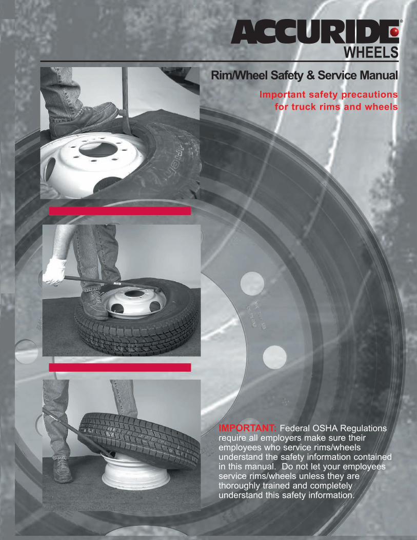
Rim/Wheel Safety & Service Manual Important safety precautions for truck rims and wheels IMPORTANT: Federal OSHA Regulations require all employers make sure their employees who service rims/wheels understand the safety information contained in this manual. Do not let your employees service rims/wheels unless they are thoroughly trained and completely understand this safety information.
Transcript of Rim/Wheel Safety & Service Manual - Accuride Corporation
Rim/Wheel Safety & Service Manual
Important safety precautions
for truck rims and wheels
IMPORTANT: Federal OSHA Regulationsrequire all employers make sure theiremployees who service rims/wheels understand the safety information containedin this manual. Do not let your employeesservice rims/wheels unless they are thoroughly trained and completely understand this safety information.
For additional copies of this Rim/Wheel Safety & Service Manual
and other information call or write:
Accuride Corporation
Literature Distribution
7140 Office Circle
P.O. Box 15600
Evansville, IN 47716
812.962.5000
800.626.7096
Accuride Field Engineering
800.869.2275
www.accuridewheels.com

1
I
II
III
IV
V
VI
VII
VIII
IX
X
XI
XII
XIII
XIV
XV
XVI
TABLE OF CONTENTS
SECTION PAGE
I Safety Warning 2
II Training of Employees Who Service Truck Tires and Rims/Wheels 3
III Safety Procedures for Servicing Truck Tires and Rims/Wheels 4
IV Correct Names of Rim/Wheel Components and Attaching Parts 12
V Important Equipment for Tire and Rim/Wheel Servicing 16
VI Recommended Tools for Servicing Truck Tires and Rims/Wheels 18
VII How to Identify Damaged Rims/Wheels 20
VIII How to Properly Maintain Rim/Wheel Components 23
IX Chart for Properly Matching Side and Lock Rings to Rims/Wheels 24
X Chart for Properly Matching Truck Tires to Rims/Wheels 25
XI Tire Mounting and Demounting Instructions
◆ 5° Commander®, VE 5°, and Convertible CR3 and FL3 3-Piece Rims/Wheels 26
◆ LW, LB, MS, and Convertible CR2 and FL2 2-Piece Rims/Wheels 27
◆ 15° Drop-Center Tubeless Rims/Wheels and Accuride Tubeless Aluminum Wheels 28
◆ 5° Drop-Center Wheels: 16x6K and 16x7K 30
◆ Duplex® 15° Drop-Center Tubeless Rims/Wheels 32
◆ Machine Mounting for Light Truck Tires (Single Piece Wheels) 34
◆ Machine Mounting for Heavy Truck Tires (Single Piece Rims/Wheels), Including Aluminum Wheels 37
XII Procedures for Inspecting and Installing Accuride Rims/Wheels on Vehicles
◆ Heavy Truck Steel Disc Wheels 38
◆ Heavy Truck Aluminum Wheels 44
◆ Duplex® Rims/Wheels for Wide Base Tires 48
◆ Light and Medium Truck Steel Disc Wheels 50
◆ Demountable Rims 53
XIII Procedures for Installing Wheel-Guard® Separator Plates on Vehicles 56
XIV Finish Coatings 57
XV OSHA Standard 29 CFR Part 1910.177 (Servicing Multi-Piece and Single Piece Rim/Wheels) 58
XVI Employee Safety Record Inside Back Cover

2
SECTION I: SAFETY WARNINGAccuride wants you to use all rim/wheel and tire components with safety and satisfaction.
Improper handling and assembly of truck tires and rims/wheels can cause serious or fatal accidents. Components can explode
at any time when proper procedures have not been followed, including during:
◆ removal from vehicle
◆ demounting
◆ inflation
◆ later handling or while on the vehicle
Follow these guidelines:
◆ Do not service any tires or rims/wheels without proper training. (Refer to OSHA standard in the back of this manual.)
◆ Use recommended tools and safety equipment.
◆ Use clean, matching components in good condition. Scrap any worn-out, damaged, excessively rusted, or
corroded parts.
◆ Learn and follow safe operating procedures. Every time.
◆ Assemble components according to recommended procedures. Don't take shortcuts.
◆ If you aren't sure about a procedure or can't find size markings on the components, don't mount and inflate the tire.
Get expert help.
Prevent injuries and costly damage. Read, understand, and follow this manual.
SAFETY WARNING: An exploding tire or rim part can injure or kill. The air pressure in an inflated truck tire
is explosive enough to burst tire/rim components apart with great force. This is true of both single piece and
multi-piece assemblies. To help avoid accidents, follow all instructions below. Read the Safety Procedures in
Section III, and follow all guidelines in this manual.

3
I
II
SECTION II: TRAINING OF EMPLOYEES WHO SERVICE
TRUCK TIRES AND RIMS/WHEELS
The following Accuride Safety and Service information is available free of charge:
◆ Multi-Piece Rim Matching Chart (OSHA)
◆ Demounting and Mounting Procedures for Truck/Bus Tires (OSHA)
◆ Rim and Ring Matching Chart for Accuride Rim/Wheel Parts
◆ Wheel Out of Service Wall Chart
◆ Hub Piloted/Stud Piloted Wheel Mounting System Identification Chart
◆ Accuride Video Program (DVD) “Servicing Single & Multi-Piece Wheels”
◆ Accuride Video Program (DVD) “Servicing and Maintaining Disc Wheels”
◆ Accuride Video Program (DVD) “Accu-Forge® Aluminum Wheels - The Bright Performers”
◆ Accuride Video Program (DVD) “Servicing and Maintaining Demountable Rims”
Accuride Wheels also has Rim/Wheel information available free of charge in French and Spanish.
See inside front cover for ordering instructions.

4
SECTION III: SAFETY PROCEDURES FOR SERVICING
TRUCK TIRES AND RIMS/WHEELS
The following guidelines are very important safety procedures. If you service truck tires and rims/wheels, READ,
UNDERSTAND, and FOLLOW these safety procedures. Improper service procedures can lead to serious, even fatal,
accidents for you or others.
Note: For mounting and demounting steps for specific rim/wheel types see Section XI, beginning on page 26, in this manual.
1. DEFLATE TIRES BEFORE SERVICING
◆ Always deflate the tire completely before removing from vehicle (deflate both tires of a dual assembly). Unseen
damage could cause the assembly to explode during removal if the tire is removed while still inflated.
◆ Remove valve core to ensure the tire is deflated.
◆ Run a piece of heavy wire through the valve stem to make sure stem is not plugged.
Run a wire through the valve stem.
◆ Always deflate, remove from the vehicle, disassemble, and inspect a tire and rim assembly that has been operated in
a run-flat or underinflated condition (80% or less of recommended pressure). This is required by OSHA Standard
1910.177.
◆ In dual assemblies use an air gauge and check the pressure in both tires. You may not be able to tell if only one tire
is flat or underinflated, because the weight of the vehicle is carried by the other tire.
"Eyeballing" the tire or "thumping" it does not tell you the pressure reading. Always use an air gauge to measure
tire pressure.
WARNING: Do not add air to tire and rim assemblies that have been operated in a seriously underinflated
or flat condition. Adding air to such an assembly can cause it to separate explosively. The tire can explode
causing serious or fatal injury.

5
III
◆ Don't stand in front of a tire/rim during deflation. In case of an explosive disassembly, you want to be out of the
trajectory (danger zone).
2. INSPECT PARTS BEFORE ASSEMBLY
USE ONLY PROPERLY MATCHING PARTS: Rims and rings must match by size and type (See page 24 for more details).
Be sure all parts of your assembly are correctly matched. Remember: Just because parts arrive together doesn't mean they
belong together.
◆ Size and type stamping appears on every Accuride rim or side/lock ring. The stamping is generally found on the
rim near the valve slot. If you cannot read the size or type stampings on any part, do not use the parts. Such parts
should be destroyed and discarded.
◆ Rim components must not be interchanged
except as provided for in the Multi-Piece
Rim Matching Chart. See page 3 to get free
copies of these charts.
◆ Be sure your tire size is approved for your
rim. Rims/Wheels can accommodate tires of
varying widths. Check the chart on page 25.
◆ Be sure the diameter shown on the tire
exactly matches the diameter stamped on
the rim/wheel. Don't rely on eyeball
estimates. Even a small difference could
cause an accident.
WARNING: Mismatched tire and rim components may explode and cause serious injury or death.

6
SECTION III: SAFETY PROCEDURES FOR SERVICING
TRUCK TIRES AND RIMS/WHEELS (continued)
BE SURE PARTS ARE IN GOOD SHAPE. Examine parts before assembling.
It takes only a few moments to inspect the rim and side/lock rings for problems. Those few moments could save your life.
◆ Do not use damaged, worn out, or cracked parts. A leak in a tubeless assembly may be caused by a cracked rim.
Do not try to repair cracked rims. Do not put a tube in a tubeless assembly to correct a leak. Destroy any cracked
rim; it could cause an accident. For more information, see pages 20 through 22.
◆ Check all metal surfaces for rust, corrosion, cracks, bent flanges, sprung side/lock rings, and deep tool marks on
rings or in gutter areas. The illustrations below show some of these conditions. For more information, see pages 20
through 22.
WARNING: Mounting a smaller diameter tire on a larger diameter rim/wheel (for example, a 16-inch tire on a
16.5-inch rim/wheel) can result in failure of the tire bead during mounting or airing. Mounting a larger diameter tire
on a smaller diameter rim can result in unseating of the tire bead during operation. The tire may explode, striking a
worker or bystander with deadly force. Check tire and rim/wheel diameter before starting to mount the assembly.
Erosion and chipping of bead
seat of lock ring
Sprung side ring Cracks through continuous
side ring spreading laterally
through the entire section.
Cracks in the rim base, in the
back flange and gutter areas.
Deep tool marks on flange
and gutter.

7
III
If you find parts with these problems, destroy them. There is no way to repair them. See pages 20 through 22 for more on these
problems and what to do about them.
◆ For tubeless rims: inspect the valve stem to ensure that it is in good condition, is not cracked or bent irregularly, and
is capable of handling proper air pressure. Replace the valve stem as necessary.
3. REPLACE DAMAGED PARTS
◆ Replace the part if there is any loss of contour or metal thickness. Loss of contour means a wearing away of the
metal mating surfaces of the rim base or side/lock rings.
◆ Destroy and discard any rim bases and side/lock rings which are deformed or pitted from corrosion, broken, or
cracked.
◆ Never rework, weld, braze, or otherwise heat any cracked, broken, or damaged rim/wheel components. Repaired
rim components may fail during inflation or later vehicle use.
◆ Never weld on a rim/wheel component any time, but especially while a tire is mounted. Heat from the welding torch
causes explosive gases to be released from the rubber tire, possibly causing an explosion.
If you suspect damage in any rim/wheel component, replace the part. You'll be giving better service to your customer and you
will be protecting yourself from accidents.
4. PREPARE PARTS BEFORE ASSEMBLING
Remove all rust, corrosion, dirt, and other foreign material from all metal surfaces. Take particular care in the rim gutter and bead
seat areas. Also, check the mating surfaces of side/lock rings in multi-piece assemblies. For more details about proper
rim/wheel maintenance, see page 23.
PAINT RIM WITH FAST-DRYING PRIMER
A good way to prevent dangerous rust build-up is painting the rim with a fast-drying primer. See page 23 for this maintenance
procedure. Always allow paint to dry before assembling components.
WARNING: Use of damaged parts is very dangerous. These parts can fail during inflation, later handling, or
while on the vehicle. You or someone else could receive serious or fatal injuries.
WARNING: Dirt and rust can prevent rim components from seating properly or cause a bead hang-up (tire
bead not seating properly). Assembling such components can lead to explosive separation, resulting in serious
or fatal injury.
Out of flat rings. Out of round rims. Cracks in rim base.

8
SECTION III: SAFETY PROCEDURES FOR SERVICING
TRUCK TIRES AND RIMS/WHEELS (continued)
LUBRICATE COMPONENTS BEFORE ASSEMBLY
Use only lubricants recommended by rim and tire makers, such as vegetable oil and animal soap solutions. If a lubricant is water
based, it should contain a rust inhibitor. When dry, the lubricant should not remain slippery. Do not use petroleum, silicon, or
solvent-based lubricants as these may damage the tire rubber or cause rust buildup or tire-to-rim slippage.
Apply an approved tire lubricant to rim bead seat area, tire beads, tire flap, and other rim to tire contact surfaces just before
mounting tire. See Section XI, beginning on page 26, for assembly details.
5. PROTECT YOURSELF DURING INFLATION
You can protect yourself and bystanders during inflation by always
observing the following safety procedures. If you cut corners on
safety procedures you may cause a serious or fatal accident.
◆ Always inflate in a safety cage or other OSHA
approved restraining device.
◆ Always use a clip-on air chuck and remote in-line
valve and gauge.
◆ Always stand back. Keep yourself and others
away from and out of the trajectory of the inflating
assembly. Don't lean or put any part of your body
on the restraining device. The air blast alone, or
movement of the restraining device, could cause
injury if an explosion occurs.
If tire beads are difficult to seal, use an approved device such as an
inflation ring to seat the tire. Tire bead seating equipment like this
inflation ring (shown below) is available to help seat beads of
tubeless tires.
WARNING: Failure to follow proper inflation procedures can expose you or bystanders to an explosion
resulting in serious injury or death.
Safety Cage
In-line Valve and Gauge
Clip-on Air Chuck Inflation Ring

9
III
WARNING: Never pour or spray any flammable substance (such as ethyl ether or gasoline) into or onto a
tire and light it to seat the beads. This practice is very dangerous and can cause a severe explosion or
undetected damage to the tire or rim, leading to serious or fatal injury. Never put any flammable substance
into or on a tire or rim/wheel for any purpose whatsoever.
◆ Always inflate in a safety cage. However, when a tire is being partially inflated (without restraining device) to round
out the tube or seat the side/lock ring, do not inflate to more than 3 psi. Further inflation could result in explosive
separation.
◆ Never inflate to more than 40 psi to seat tire beads. More inflation can cause a tire explosion. If tire beads do not
seat when inflated to 40 psi, deflate assembly, re-inspect the components, properly assemble, and follow proper
inflation procedures to re-inflate.
◆ After the tire is fully inflated, inspect the tire, rim, and rings for proper seating before removing assembled unit from
the restraining device.
◆ Never try to correct the seating of the side/lock rings by hammering, striking, or forcing the parts during servicing,
inflation, or after inflation. The components could separate explosively.
◆ If the assembled unit is not fully seated, release the air by using your remote in-line valve that both inflates and
deflates. Then remove the valve core to make sure the tire is fully deflated, and remount.
◆ Tires on vehicles with more than 80% of the recommended air pressure can be inflated on the vehicle. For safety,
use an in-line valve and gauge for inflation, stand clear, and keep others out of the trajectory (danger zone).
Remember: Tire/rim assemblies operated in a run-flat or underinflated condition (80% or less of recommended
pressure) can explode if you try to reinflate them. Deflate, remove from vehicle, and disassemble. Then check the
mating surfaces of parts. If they are damaged, scrap them.
TWO-PIECE RIMS
Correct Incorrect Incorrect
Correct Incorrect Incorrect
THREE-PIECE RIMS
The components in a correctlyassembled two-piece rim fitsnugly and are lockedtogether.
An incorrectly assembled or
damaged two-piece rim could
have a large gap in side ring.
Components are not firmly
locked in place.
An incorrectly assembled or
damaged two-piece rim could
have components not firmly
locked in place.
A three-piece rim that is
correctly assembled has
firmly fitted components that
are locked together.
An incorrectly assembled or
damaged three-piece rim could
have a large gap in the lock
ring. The components are not
firmly locked in place.
An incorrectly assembled or
damaged three-piece rim could
have components not firmly
locked in place

10
SECTION III: SAFETY PROCEDURES FOR SERVICING
TRUCK TIRES AND RIMS/WHEELS (continued)
6. PROTECT YOURSELF AFTER INFLATION
◆ Whenever handling inflated truck tires and wheels, stay out of the trajectory (danger zone). Warn anyone near the
trajectory, too. In the performance of certain servicing procedures, such as installing or removing a rim/wheel, it may
be necessary to be within the trajectory. Extreme care should be followed.
◆ Study the diagrams above. Learn the trajectories and stay clear of them.
◆ Note that under some circumstances the trajectory may take a different path from the one you expect.
LOADING
Each tire, wheel, and axle has its own maximum rating. Do not load and inflate the tire/wheel/axle system beyond the capacity of
the lowest rated component. Overloading causes tire failure and injury accidents.
◆ If a tire has less capacity (load/inflation) than the rim/wheel or axle (GAWR) it is used with, use the capacity limits of
the tire, not the wheel or axle. The GAWR can be found on the vehicle placard.
◆ If a rim/wheel has less capacity (load/inflation) than the tire or axle (GAWR) it is used with, use the capacity limits of
the rim/wheel, not of the tire or axle. The GAWR can be found on the vehicle placard.
Rims and wheels produced by Accuride are designed and tested to meet the requirements of specific tires or vehicles. Some
high load capacity/high inflation tires are being used in North America. These ratings may exceed the rated capacity for all
rims and wheels produced by Accuride. These high load capacity/high inflation tires cannot be used on existing rims and
wheels unless you keep load and tire inflation pressure below the maximum load rating and inflation rating of the rims or wheels.
You can find further information in the Accuride Wheels Product Catalog. Read and understand this information before using
these products on vehicles.
WARNING: If proper servicing, maintenance, or assembly procedures have not been followed, the tire/wheel
assembly may explode at any time, resulting in serious or fatal injuries to you or others.
TRAJECTORY
TRAJECTORY

11
III
7. INSTALL WHEEL ON VEHICLE PROPERLY
When you mount the rim/wheel on the vehicle, be sure to pay attention to the following:
◆ Proper size of nut and stud (and clamp where required).
◆ Proper installation of spacer band on dual demountable rim assemblies.
◆ Correct nut tightening sequence.
◆ Correct torque (tightening expressed in foot-pounds) of the nuts. See the section on Procedures for Inspecting and
Installing Accuride Rims/Wheels on Vehicles, pages 38 through 55.
For installation procedures for specific types of Accuride wheels and rims, see the sections listed below:
◆ Heavy Truck Steel Disc Wheels, see pages 38 through 43.
◆ Heavy Truck Aluminum Wheels, see pages 44 through 47.
◆ Duplex® Rims/Wheels for Wide Base Tires, see pages 48 through 49.
◆ Light and Medium Truck Steel Disc Wheels, see pages 50 through 52.
◆ Demountable Rims, see pages 53 through 55.
8. TAKE CARE DURING VEHICLE OPERATION
Inspect rims and wheels for damage during tire checks and at periodic maintenance intervals. Remove and replace damaged or
worn parts.
◆ Do not run vehicle on one tire of a dual assembly. When there is loss of air in a dual tire, the carrying capability is
reduced and the load must be carried by the other tire and rim. See that both tires are inflated to equal
recommended pressures before further operation.
◆ Tire/rim assemblies operated in a run-flat or underinflated condition (80% or less of recommended pressure) can be
worn, dislodged, or damaged. If you add air to this assembly, it may explode and cause serious injury or death.
Instead, fully deflate, remove from vehicle, and disassemble. After disassembly, check the mating surfaces of parts.
If the parts are sound, reassemble and inflate in a safety cage. If parts are damaged or worn, scrap them.
◆ Recheck the torque level of nuts between the first 50 and 100 miles of operation and as part of a vehicle’s ongoing
scheduled maintenance or at 10,000 mile intervals, whichever comes first. Retighten, if necessary, to the
recommended torque using the proper sequence.
WARNING: Improperly installed wheels can fail and lead to an accident. Serious injury or death may result.
WARNING: Improperly maintained rims and wheels can fail and lead to an accident. Serious injury or death
may result.

12
SECTION IV: CORRECT NAMES OF RIM/WHEEL
COMPONENTS AND ATTACHING PARTSThere is confusion over the terms "wheel" and "rim" in the industry. Please read the following definitions so you will understand
the terms appearing in this manual. Remember, a rim is not a wheel and a wheel is not a rim. Likewise, there is an important
difference between a side ring and a lock ring.
RIM
The rim supports the tire. There are two types of rims: a single piece rim (tubeless—some 16 inch single piece rims are either
tubeless or tube-type) and a multi-piece rim (tube-type). A SINGLE PIECE RIM is a continuous one-piece assembly. A MULTI-
PIECE RIM is an assembly consisting of a base and either a side ring or a side and lock ring depending on the type. A
DEMOUNTABLE RIM does not have a center disc and is clamped onto a cast spoke wheel.
DISC WHEELS
A combination of a rim and a disc permanently attached to the rim and attached to the hub by studs and nuts.
Tubeless Demountable Rim (single piece)
shown in cross section
Tube-Type Demountable Rim Assembly (multi-piece)
Tubeless Disc Wheel Tube-Type Disc Wheel Assembly
13
IV
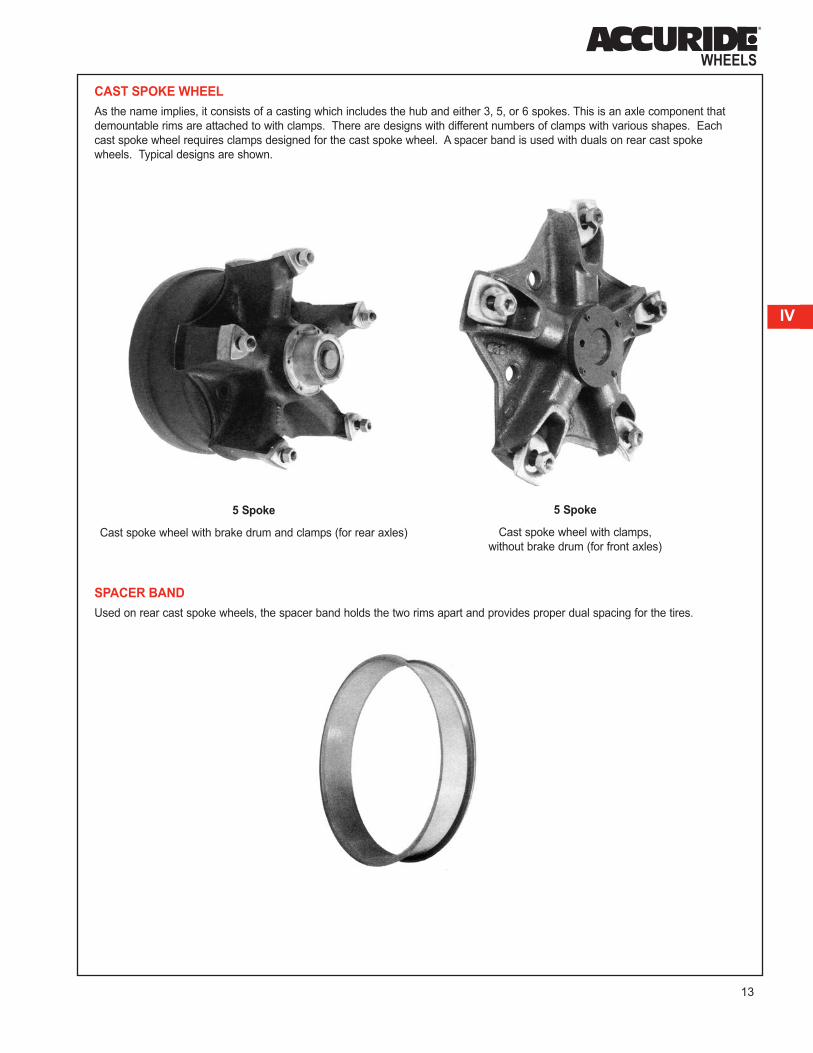
CAST SPOKE WHEEL
As the name implies, it consists of a casting which includes the hub and either 3, 5, or 6 spokes. This is an axle component that
demountable rims are attached to with clamps. There are designs with different numbers of clamps with various shapes. Each
cast spoke wheel requires clamps designed for the cast spoke wheel. A spacer band is used with duals on rear cast spoke
wheels. Typical designs are shown.
SPACER BAND
Used on rear cast spoke wheels, the spacer band holds the two rims apart and provides proper dual spacing for the tires.
5 Spoke
Cast spoke wheel with brake drum and clamps (for rear axles)
5 Spoke
Cast spoke wheel with clamps,
without brake drum (for front axles)

14
SECTION IV: CORRECT NAMES OF RIM/WHEEL
COMPONENTS AND ATTACHING PARTS (continued)
SPLIT SIDE RING
In two-piece assemblies, the side ring retains the tire on one
side of the rim. The fixed flange supports the other side. The
split side ring is designed so that it acts as a self-contained lock
ring as well as a flange.
FLANGE OR CONTINUOUS SIDE RING
In three-piece assemblies, the flange or continuous side ring
supports the tire on one side of the rim. The continuous side
ring is, in turn, held in place by a separate split lock ring.
SPLIT LOCK RING
All lock rings are split. In three-piece assemblies, the lock ring
is designed to hold the continuous side ring on the rim.
Split Side Ring
Flange or
Continuous Side Ring
Split Lock Ring

15
IV
STUDS AND NUTS FOR DISC WHEELS
Typical examples of studs, nuts and clamping plates used with disc wheels are illustrated in this section. A typical stud (Fig. 1)
used with in-board brake drums has a 3/4" thread on both ends, a shoulder with two flats, and is longer from the shoulder on the
one end with an unthreaded section. The flat surfaces of the shoulder fit into the recessed outer surface of the hub to keep the
stud from turning. The smooth portion is long enough to fit through the hub and the brake drum, and is then held in place by a
back or jam nut (Fig. 2). For outboard brake drums a serrated stud with threads on one side is typically used (Fig. 3).
On front stud mount wheels, an outer cap nut (Fig. 4) or (Fig. 6) is used. On stud mount rear dual wheel applications, the inner
wheel is held in place by an inner cap nut (Fig. 5) and the outer wheel by an outer cap nut (Fig. 6).
For hub mount wheels which pilot from the center hole, flange nuts are used on both the front and rear wheels. One-piece
flanged cap nuts (Fig. 7) are used on light truck and medium truck applications. Heavy trucks and buses and some light trucks
use a two-piece flange nut or swiveling lug nut (Fig. 8) when hub mount wheels are used. Some light trucks use a clamping
plate (Fig. 9) and 90° cone nuts (Fig. 10) for both the front and rear wheel. Light trucks which use single wheels on the front and
rear axle require 90° cone nuts or 60° cone nuts (Fig. 11), depending on the truck manufacturer.
RIM CLAMPS, STUDS AND NUTS FOR DEMOUNTABLE RIMS
The stud for cast spoke wheels (Fig. 12), threaded on both ends, is installed in a threaded hole at the end of a spoke. The front
clamp (Fig. 13) and a rear clamp (Fig. 14) hold the demountable rim in position with studs and nuts (Fig. 15). A clamp for a
three-spoke wheel with two stud holes is shown in (Fig. 16).
Fig. 1Fig. 2
Fig. 5
Fig. 3
Fig. 6
Fig. 7
Fig. 8
Fig. 4
Fig. 9
Fig. 10
Fig. 11
Fig. 12
Fig. 15
Fig. 16
Fig. 13
Fig. 14

16
SECTION V: IMPORTANT EQUIPMENT FOR
TIRE AND RIM/WHEEL SERVICING
Using proper tools and safety equipment can help prevent personal injuries and costly damage. Remember, an inflated truck tire
contains explosive energy. This can cause the tire/rim components to burst apart with great force. Protect yourself. Use the
servicing equipment recommended below.
1. Always inflate in a safety cage using a clip-on
air chuck or use an OSHA-approved restraining
device with a clip-on air chuck.
◆ This is a safeguard against injury resulting from
assembly errors.
◆ A safety cage is your best protection if there is an
explosion during inflation.
2. Always use a clip-on air chuck with an in-line valve and gauge with sufficient length of hose to stand clear.
◆ A clip-on air chuck allows you to keep your hands, arms, and body clear during inflation.
◆ An in-line valve allows you to control the air flow while standing away from the assembly.
◆ An in-line gauge allows you to monitor the air pressure going into the tire during inflation.
WARNING: Facing the side/lock rings against a wall or other permanent structure during inflation is not safe.
If the assembly explodes, you can be struck by flying components. Fully restrain the tire and rim/wheel
during inflation.
Safety Cage
WARNING: Inflating a truck tire with a hand-held air chuck is dangerous. You have to put your hand
inside the safety cage or the restraining device. You can't stand clear. You can be seriously injured.
In-line Valve and GaugeClip-on Air Chuck

17
V
3. Provide OSHA reference materials.
◆ A demounting and mounting procedure chart
shows you the proper procedure to follow when
servicing truck tires and rims/wheels.
◆ A matching chart shows you which components you
can put together safely. You need to properly match
the rim and the side and lock rings when servicing
multi-piece rims/wheels. Remember, you also need
to match the rim/wheel to the tire.
Typical examples of these charts are:
➡ “Demounting and Mounting Procedures for
Truck/Bus Tires"*
➡ “Multi-Piece Rim Matching Chart"*
* These reference materials are available for
download from OSHA at:
http://www.osha.gov/pls/publications
Reference numbers are:
Demounting and Mounting Procedures for Tubeless Truck and Bus Tires Chart - Tire Chart (OSHA 3401)
Demounting and Mounting Procedures for Tube-type Truck and Bus Tire Chart - Tire Chart (OSHA 3402)
Multi-Piece Rim Matching Chart - Tire Chart (OSHA 3403)
Servicing Multi-Piece and Single-Piece Rim Wheels 29 CFR 1910.177 Manual - Tire Chart (OSHA 3421)
The following Accuride Safety and Service information is also
available free of charge:
◆ Multi-Piece Rim Matching Chart (OSHA)
◆ Demounting/Mounting Procedures Wall Chart (OSHA)
◆ Rim and Ring Matching Chart for Accuride
Rim/Wheel Parts
◆ Wheel Out of Service Guidelines Wall Chart
◆ Hub Piloted/Stud Piloted Wheel Mounting System
Identification Chart
◆ Accuride Video Program (DVD) “Servicing Single
& Multi-Piece Wheels”
◆ Accuride Video Program (DVD) “Servicing and
Maintaining Disc Wheels”
◆ Accuride Video Program (DVD) “Accu-Forge®
Aluminum Wheels - The Bright Performers”
◆ Accuride Video Program (DVD) “Servicing and
Maintaining Demountable Rims”
See inside front cover for ordering instructions.
Accuride also has Rim/Wheel information available free of charge in French and Spanish.
4. Maintain and use current rim/wheel manuals.
◆ A current rim/wheel manual should be available in the service area. This manual should contain instructions for the
type of rims/wheels you service.
◆ Rim/wheel manuals are available from rim/wheel manufacturers or your local rim/wheel distributor.
5. Use proper tools.
◆ Use only the tools recommended by the manufacturer for servicing the specific tire and rim.
◆ Pages 18 and 19 of this manual show the proper tools and pages 26 through 37 show the mounting and
demounting instructions for servicing truck tires and rims/wheels.

18
SECTION VI: RECOMMENDED TOOLS FOR SERVICING
TRUCK TIRES AND RIMS/WHEELS
Use only recommended tools for mounting and demounting truck tires and servicing rims/wheels. The use of the proper tools
allows the safe mounting and demounting of tires and rims/wheels and prevents damage to the rim. The use of improper tools
can cause damage to the components.
◆ Do not strike components of a rim/wheel assembly with a hammer or similar instrument in an attempt to seat the rings
into the gutter. This can cause damage to the rim and rings which could lead to component failure. Rubber,
leather-faced, or plastic rim mallets may be used to tap rings into the gutter. Do not use lead, steel, or bronze rim
mallets which can chip or shatter, causing injury.
◆ The duck bill hammer should not be used to strike the bead/rim area. This could cause damage to the rim or tire.
◆ Duck bill hammers which are a combination rim mallet and driving iron should only be used in the following manner:
The wedge end should be placed between the tire and rim flange and the opposite side struck by another rim mallet
to separate the tire bead from the rim flange.
◆ Bead seal breaking machines may be used with tires/rims and may make tire demounting easier.
The following tools are recommended for use with Accuride rims/wheels. The specific tools for each rim type are shown in the
mounting and demounting instruction pages for that rim type.
1. Rim Tools
Tubeless Tire Iron Duplex Extension Tool
Duplex "C" Tool Lock Ring Tool

19
VI
2. Bead Seal Breaking Tools
Swan Neck Bead Tool
Bead Seal Breaking Machine
Driving Iron
Duck Bill Hammer
3. Rim Mallet 4. Self-Locking Pliers
5. Tire Mounting Machine 6. Lubricant and Brush

20
SECTION VII: HOW TO IDENTIFY DAMAGED RIMS/WHEELS
Rim/wheel components can become damaged. Check all metal surfaces for rust or corrosion buildup, cracks in metal, bent
flanges and side rings, and deep rim tool marks on rings or in gutter areas. Watch for the problems illustrated on the following 3
pages and take the corrective actions to prevent further problems. Remember, it is dangerous to assemble cracked, bent,
severely corroded, or sprung rim/wheel components. Such items should be destroyed and discarded.
RIM BASE CRACKS
RIM BASE DISTORTION MOUNTING RING PROBLEMS

21
VII
TUBELESS RIM LEAKS
DISC WHEEL CRACKS/BOLT HOLE DISTORTION
22
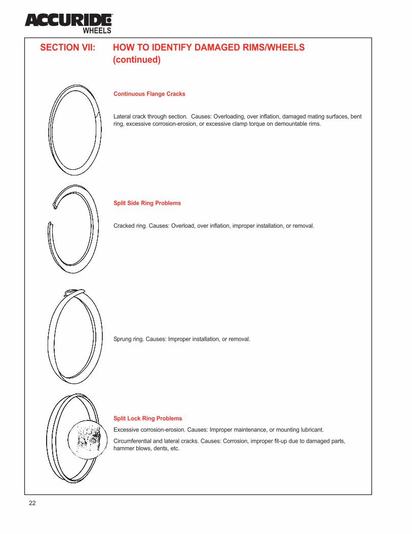
SECTION VII: HOW TO IDENTIFY DAMAGED RIMS/WHEELS
(continued)
Continuous Flange Cracks
Lateral crack through section. Causes: Overloading, over inflation, damaged mating surfaces, bent
ring, excessive corrosion-erosion, or excessive clamp torque on demountable rims.
Split Side Ring Problems
Cracked ring. Causes: Overload, over inflation, improper installation, or removal.
Sprung ring. Causes: Improper installation, or removal.
Split Lock Ring Problems
Excessive corrosion-erosion. Causes: Improper maintenance, or mounting lubricant.
Circumferential and lateral cracks. Causes: Corrosion, improper fit-up due to damaged parts,
hammer blows, dents, etc.

23
VII
VIII
SECTION VIII: HOW TO PROPERLY MAINTAIN
RIM/WHEEL COMPONENTS
Thoroughly remove rust, dirt, and other foreign materials from
all surfaces. Hand or electric wire brushes or sand blasting
may be used.
Gutter of rim base should be cleared of rust and other
materials that could obstruct seating of rings.
Rings should be cleaned with wire brushes. Pay particular
attention to seating surfaces and bead seat areas.
Bead seat areas of rim should be free of rust and rubber
deposits. This is especially important for drop-center tubeless
rims, because the bead seat is the air-sealing element.
Paint rim by brush or spray with a fast-drying metal primer.
Surfaces should be clean and dry prior to painting. Ensure
that bare metal areas on outside or tire side of rim are
covered. This is especially important on drop-center tubeless
rims, because warm and sometimes moist air is in constant
contact with the metal surface on the tire side of the rim.
Wheel disc mating surfaces must be kept flat. Remove any
metal projections, burrs at the stud hole chamfers and paint
buildup.

24
SECTION IX: CHART FOR PROPERLY MATCHING
SIDE AND LOCK RINGS TO RIMS/WHEELSIt is important to recognize that the various types and sizes of highway rims produced by their manufacturers all differ to some degree in
design. This is particularly important of removable rings, since side and lock rings of different rim types are not generally
interchangeable. Some rings are common to two types or sizes, and are identified with each size and type.
Some rings may appear to fit but they actually do not fit properly on the rim base. Serious accidents to personnel may result from the
use of mismatched rings. IF YOU CAN'T FIND THE STAMPING OR READ THE STAMPING ON MULTI-PIECE RIMS, WHEELS OR
RINGS, DON'T USE THE PARTS. THEY SHOULD BE DESTROYED AND DISCARDED.
The chart below shows the only components which are interchangeable with Accuride parts.
Rim and Ring Matching Chart for Accuride Rim/Wheel Parts
Instructions On How To Use Charts
The following charts list combinations of components that are approved for use together. The stamped marking on the rim base is noted
in the left hand column. Rim bases with a particular stamping should be matched only with the side rings (2-piece assemblies) or side
and lock rings (3-piece assemblies) listed directly to the right.
For example: A 20x7.0 CR rim base can be used only with a 2-piece 20x6.5-7.0 CR or R6520CR side ring or a 3-piece 20x6.5-7.0 CR or
LR20x6.5-7.0 CR or LR6520CR lock ring and 20x7.0 5°-FL-CR or F20x7.0 CR or F7020CR side ring.
The charts below note the only components which are interchangeable with Accuride parts. For more comprehensive information,
including components made by other manufacturers, consult the OSHA "Multi-Piece Rim Matching Chart".
2-Piece FL-CR Type Convertible Rims
RIM BASE MARKINGS SIDE RING MARKINGS
20x6.5 CR or B6520CR 20x6.5-7.0 CR or R20x6.5-7.0 CR or
R6520CR
20x7.0 CR or B7020CR 20x6.5-7.0 CR or R6520CR
20x7.5 FL or B7520FL 20x7.5 FL or R20x7.5 FL or R7520FL
22x7.5 FL or B7522FL 22x7.5 FL or R22x7.5 FL or R7522FL
2-Piece LB - LW Type Rims
RIM BASE MARKINGS SIDE RING MARKINGS
20x6.5 LB or B6520LB 20x6.5-7.0 LBLW or
R20x6.5-7.0 LBLW or R6520LW
20x7.0 LB or B7020LB 20x6.5-7.0 LBLW or
R20x6.5-7.0 LBLW or R6520LW
20x7.5 LB or B7520LB or 20x7.5-8.0 LBLW or
G20750B R20x7.5-8.0-9.0 LBLW or
R8020LW
22x7.5 LB or B7522LW or 22x7.5-8.0 LBLW or
G22750B R22x7.5-8.0-9.0 LBLW or
R8022LW
20x7.5 LW or 20x7.50LW or 20x7.5-8.0 LBLW or
B7520LW or G20750B 20x7.5-8.0-9.0 LBLW or R8020LW
20x8.0 LW or 20x8.00 LW or 20x7.5-8.0 LBLW or
B8020LW or G20800B R20x7.5-8.0-9.0 LBLW or R8020LW
2-Piece MS Type Rims
RIM BASE MARKINGS SIDE RING MARKINGS
20x7.5 MS 20x7.5 MS
3-Piece FL-CR Type Convertible Rims
RIM BASE MARKINGS LOCK RING MARKINGS SIDE RING MARKINGS
20x6.5 CR or 20x6.5-7.0 CR or 20x6.5 5°-FL-CR or
B6520CR LR20x6.5-7.0 CR or F20x6.5-CR or
LR6520CR F6520CR
20x7.0 CR or 20x6.5-7.0 CR or 20x7.0 5°-FL-CR or
B7020CR LR20x6.5-7.0 CR or F20x7.0CR or
LR6520CR F7020CR
20x7.5 FL or 20x7.5 FL or 20x7.5-8.0 5°-7.5FL or
B7520FL LR7520x7.5 FL or 20x7.5 5°-FL or
LR7520FL F20x7.5FL or
F7520FL
22x7.5 FL or 22x7.5 FL or 22x7.5-8.0 5°-7.5FL or
B7522FL LR22x7.5 FL or 22x7.5 5°-FL or
LR7522FL F22x7.5FL or
F7522FL
3-Piece 5° - VE 5° Type Radial Commander® Rims
RIM BASE MARKINGS LOCK RING MARKINGS SIDE RING MARKINGS
20x7.0 5° 20x7.0-7.5-8.0 5° 20x7.0 5°-FL-CR or
F7020FL
20x7.5 5° or 20x7.0-7.5-8.0 5° 20x7.5-8.0 5°-7.5FL or
20x7.50 5° or 20x7.5 5°-FL or
F20750B F7520FL
22x7.5 5° or 22x7.0-7.5-8.0 5° 22x7.5-8.0 5°-7.5FL or
22x7.50 5° or 22x7.5 5°-FL or
F22750B F7522FL
20x8.0 5° or 20x7.0-7.5-8.0 5° 20x8.0 5° or
20x8.00 5° or 20x7.5-8.0 5°-7.5FL
F20800B
22x8.0 5° or 22x7.0-7.5-8.0 5° 22x8.0 5° or
22x8.00 5° or 22x7.5-8.0 5°-7.5FL
F22800B
24x8.0 5° 24x8.0 5° 24x8.0 5° or
24x7.5-8.0 5°
20x8.5 5° 20x8.5 5° 20x8.5 5°
24x8.5 5° 24x8.5 5° 24x8.5 5°
20x10.00VE 5° 20x8.5 5°/10.00VE 5° 20x8.5 5°/10.00VE 5°
WARNING: Improperly assembled parts could result in personal injury or death. Use only rings that are
stamped with the same size and type as the rim base. All components are stamped with size and type information
Do not use parts you can't identify.
◆ For typical rim stamping location see page 5.

SECTION X: CHART FOR PROPERLY MATCHING
TRUCK TIRES TO RIMS/WHEELSInformation obtained from The 2011 Tire and Rim Association Yearbook.
25
IX
X
WARNING: Failure to properly match tire and rim/wheel sizes is dangerous. Mounting a smaller diameter tire on a larger
diameter rim/wheel (for example, mounting a 16 inch tire on a 16.5 inch rim/wheel) can result in breaking the tire bead during
mounting or airing. The tire may then explode during inflation. The explosion can hurl the tire and wheel into the air striking you
or a bystander. Be sure the diameter shown on the tire exactly matches the diameter stamped on the rim/wheel.
(1) A denotes both radial and bias tires. An R indicates radial tires only.
(2) SDC denotes semi-drop center rims.
Note: For tire sizes not shown, consult the Tire Manufacturer for approved
rim contours.

26
SECTION XI: TIRE MOUNTING AND
DEMOUNTING INSTRUCTIONS
5° COMMANDER®, VE 5°, AND CONVERTIBLE CR3 AND FL3 3-PIECE RIMS/WHEELS
Tools Required:
◆ 1 Rim mallet
◆ 1 Ring tool
◆ 2 Swan necked bead tools
◆ Lubricant & brush
See Section VI, page 18, for recommended tools.
DEMOUNTING
1. Before loosening any nuts securing tire and rim assembly to the vehicle, remove valve
core and deflate tire completely. If working on duals, deflate both tires completely.
Run wire through valve stem to ensure deflation.
◆ Remove tire and rim assembly from truck and place on floor, side ring up.
◆ Insert hooked end of swan necked bead tool between side ring and side wall of
tire. Apply downward pressure on rim tools to pry bead loose from side ring.
◆ Continue prying progressively around tire until bead is completely free from side ring.
2. To remove lock ring push the side ring and tire bead down.
◆ Insert tapered end of rim tool into notch near split in lock ring.
◆ Push rim tool downward and pry lock ring outward to remove from gutter of rim base.
◆ Use hooked end of rim tool to complete removal of lock ring, progressively
working around tire. Lift off side ring.
◆ Turn assembly over. Unseat remaining tire bead from rim. Lift rim from tire.
MOUNTING
1. Inspect the tire and rim for any damage. Be sure tire size and rim size match exactly.
2. Insert tube into the tire and partially inflate to no more than 3 psi to round out tube.
◆ Apply tire lubricant to inside and outside surfaces of both beads. Lubricate
portion of tube that appears between beads.
◆ Insert flap and lubricate.
◆ Lay rim flat on floor with gutter side up. Align tube valve with rim valve slot center.
◆ Push tire onto rim. Insert valve through valve slot.
3. Place side ring on rim base. Stand on ring to position it below gutter in rim base.
◆ Snap leading end (end without notch) of lock ring into gutter of rim base.
◆ Progressively "walk" lock ring into place. Check to ensure lock ring is fully seated
in gutter.
4. Inflate to no more than 3 psi. Again check proper engagement of lock ring. If assembly is not
proper, deflate and correct. Never hammer on an inflated or partially inflated tire/rim
assembly.
5. Inflate the tire.
◆ Put tire/rim assembly in safety cage or other OSHA-approved restraining device.
Use an extension hose with an air gauge and clip-on air chuck. Stand clear of
the assembly.
◆ Inflate tire to recommended pressure to seat beads. Check to see if beads are
properly seated.
◆ Completely deflate tire to prevent buckling of tube.
◆ Reinflate tire to recommended pressure.
◆ Before removing from safety cage or restraining device - check to see that rim
component are properly seated.
WARNING: Before working on any tire/rim assembly, be sure you are trained and thoroughly familiar with the
safety guidelines in Section III of this manual. Improper servicing of tire/rim assemblies can lead to serious, even
fatal, accidents for you or others. Follow recommended mounting/demounting procedures carefully.
Gutter
Continuous Side Ring
Lock Ring
Rim Base

27
XI
LW, LB, MS, AND CONVERTIBLE CR2 AND FL2 2-PIECE RIMS/WHEELS
Tools Required:
◆ 1 Rim mallet
◆ 1 Ring tool
◆ 2 Swan necked bead tools
◆ Lubricant & brush
See Section VI, page 18, for recommended tools.
DEMOUNTING
1. Before loosening any nuts securing tire and rim assembly to the vehicle, remove valve
core and deflate tire completely. If working on duals, deflate both tires completely. Run
wire through valve stem to ensure deflation.
◆ Remove tire and rim assembly from truck and place on floor, side ring up.
◆ Insert hooked end of swan necked bead tool between side ring and side wall of tire.
Apply downward pressure on rim tools to pry bead loose from side ring.
◆ Continue prying progressively around tire until bead is completely free from side ring.
2. To remove side ring push the tire bead down.
◆ Insert tapered end of rim tool into notch and pry side ring out of gutter.
◆ Pry progressively around tire until side ring is free of the gutter.
3. Turn assembly over. Unseat remaining tire bead from rim. Lift rim from tire.
MOUNTING
1. Inspect the tire and rim for any damage. Be sure tire size and rim size match exactly.
2. Insert tube into the tire and partially inflate to no more than 3 psi to round out tube.
◆ Apply tire lubricant to inside and outside surfaces of both beads. Lubricate portion
of tube that appears between beads.
◆ Insert flap and lubricate.
◆ Lay rim flat on floor with gutter side up. Align tube valve with rim valve slot.
◆ Push tire onto rim. Insert valve through valve slot.
3. Place side ring on rim base so that ring split is opposite valve stem.
◆ Place leading end (end without notch) of ring into the groove in the rim as shown.
◆ Progressively "walk" side ring into place. Check to ensure ring is fully seated in
gutter.
4. Inflate to no more than 3 psi. Again check proper engagement of side ring. If assembly
is not proper, deflate and correct. Never hammer on an inflated or partially inflated
tire/rim assembly.
5. Inflate the tire.
◆ Put tire/rim assembly in safety cage or other OSHA-approved restraining device.
Use an extension hose with an air gauge and clip-on air chuck. Stand clear of the
assembly.
◆ Inflate to recommended tire pressure seat beads. Check to see if beads are
properly seated.
◆ Completely deflate tire to prevent buckling of tube.
◆ Reinflate tire to recommended pressure.
◆ Before removing from safety cage or restraining device - check to see that rim
components are properly seated.
Gutter
Rim Base
Split Side Ring

28
SECTION XI: TIRE MOUNTING AND
DEMOUNTING INSTRUCTIONS (continued)
15° DROP-CENTER TUBELESS RIMS/WHEELS AND
ACCURIDE TUBELESS ALUMINUM WHEELS
Tools Required:
◆ 1 Rim mallet
◆ 1 Self-locking pliers
◆ 1 swan necked bead tool
◆ 2 Tubeless tire tools
◆ Lubricant & brush
OR
◆ Tire changing machine
(Instructions on page 37)
◆ Lubricant & brush
See Section VI, page18, for recommended tools.
DEMOUNTING (By Hand)
Before loosening any nuts securing tire and rim assembly to the vehicle, remove valve core and
deflate tire completely. If working on duals, deflate both tires completely. Run wire through valve
stem to ensure deflation. Remove tire and rim assembly from truck and place on floor.
1. Loosen bead from rim:
◆ Drive the flat end of the swan necked bead tool between tire bead and rim flange.
Straighten tool to an upright position and hammer downward on the neck to pry tire
from rim.
◆ Repeat at about eight-inch intervals around flange until bead is free from rim.
◆ Turn assembly over and repeat to loosen other bead.
2. Lay assembly flat on floor with short side of rim up. Lubricate tire bead and rim.
◆ Insert curved end of tubeless tire tool in tire at valve. Step on tire opposite valve to
direct first bead into the well.
◆ Pull tool toward center of rim lifting the tire over the flange until it touches both
rim flanges.
◆ Hold tool in position with foot. Insert and pull second tool toward center of rim.
◆ Progressively work tools around rim until first bead is off rim.
3. Stand assembly in vertical position with valve near top. Lubricate second bead and rim.
Be sure opposite side of second bead is into well.
◆ Insert straight end of tool between tire bead and the back rim flange, hooking the tool
over the top of the second flange.
◆ Lean tire assembly toward tool and provide a rocking or bounding action to pry the rim
out of the assembly.
Well
Flange
Short Side
of Rim
STEEL DISC WHEEL ALUMINUM WHEEL
Well
Flange

29
XI
MOUNTING (By Hand)
1. Inspect the tire and rim for any damage. Be sure tire size and rim size match exactly.
2. Insert valve stem.
◆ Put valve stem with rubber grommet through valve hole.
◆ From opposite side (weather side), screw on valve nut. Make sure the valve is
centered and fits snugly in valve hole.
◆ Finish tightening with wrench. Do not over tighten.
3. Place rim on floor with rim short side up. With an approved tire lubricant, using a brush or
swab, lubricate both bead seats of the rim and both tire beads.
4. Lay tire on the rim.
◆ If there is a balance mark (yellow dot) indicated the light spot on the tire, line this
mark up with the valve stem.
◆ If there is a mark (red dot) on the tire indicating the high spot of tire runout, line
this up with the dimple in the wheel if it is marked. If not, line it up with the valve stem.
◆ Push lower bead over flange and into rim well.
◆ Using straight end of tool with stop resting on rim flange, pry tire over flange,
starting where tire bead crosses rim flange.
◆ Repeat progressively around the tire working with small sections until the tire is
completely over the rim.
5. Stand on tire to start upper bead over rim flange into well.
◆ When necessary, push section of bead into rim well and anchor with self-locking
pliers. Pinch pliers onto rim flange, snub side toward tire.
◆ Using spoon end of tire tool, with stop toward rim, work progressively around bead.
◆ Repeat, taking small sections around tire until bead slips over flange onto rim. If
necessary, insert second tire iron and again lubricate last 8 inches of bead before
completing the procedure.
6. Inflate the tire.
◆ Put tire/rim assembly in safety cage or other OSHA-approved restraining device.
Use an extension hose with an air gauge and clip-on air chuck. Stand clear of the
assembly.
◆ Inflate to recommended inflation pressure.
◆ Before removing from safety cage or restraining device - check to see that the
tire beads are properly seated.
For demounting and mounting by machine, see instructions at the end of this section, page 37.

30
SECTION XI: TIRE MOUNTING AND
DEMOUNTING INSTRUCTIONS (continued)
5° DROP CENTER WHEELS: 16x6K and 16x7K
Tools Required:
◆ 1 Rim mallet
◆ 1 Swan necked bead tool
◆ 2 Tubeless tire tools
◆ Lubricant & brush
OR
◆ Tire changing machine
(Instructions on page 34)
◆ Lubricant & brush
See Section VI, page 18, for recommended tools.
DEMOUNTING (By Hand)
1. Before loosening any nuts securing tire and rim assembly to the vehicle, remove valve
core and deflate tire completely. If working on duals, deflate both tires completely. Run
wire through valve stem to ensure deflation.
◆ Remove tire and rim assembly from truck and place on floor.
◆ Insert the curved end of a tire tool between the rim flange and tire.
Pry downward to unseat the bead. Work tire bead down into rim well by prying at
eight-inch intervals.
◆ Turn assembly over and repeat to loosen other bead.
2. Remove the tire:
◆ Lay assembly flat on the floor with the short side of the rim up. Lubricate the tire
bead and rim.
◆ Insert the curved end of a tubeless tire tool between the tire and rim flange at the
valve. With your shoe, press the opposite side of the tire bead down in the rim well.
Pry the bead over the rim flange.
◆ Repeat this process around the rim until the first tire bead is off the rim. Remove the
tube and flap if it is a tube-type assembly.
◆ Press the tire bead down in the rim well with your shoe. Hook the straight end of the
tire tool over the rim flange with the stop against the rim (as shown). Pry the second
bead over the flange. Continue prying until the second bead is completely off the rim.
Well
Flange
Short Side of Rim

31
XI
MOUNTING (By Hand)
Tube-Type Tires
1. Inspect the tire and rim for damage. Be sure tire and rim size match exactly.
2. Lay the wheel on the floor with the rim short side up. Apply an approved lubricant on tire
beads and mount tire onto rim by pushing first bead over rim flange by hand. Work bead
into rim well.
◆ Using the curved end of a tire tool, pry remaining portion of first bead over flange in
small amounts.
◆ Insert tube into tire. Put a small amount of air in the tube to round out the tube. Insert
flap if required.
◆ Apply an approved lubricant to the inside and outside surfaces of both beads and
portion of tube appearing between beads.
◆ Align and insert valve stem into rim valve hole.
◆ Repeat this process with second bead of tire.
3. Inflate the tire:
◆ Put tire/rim assembly in safety cage or other OSHA-approved restraining device. Use
an extension hose with an air gauge and clip-on air chuck. Stand clear of the
assembly.
◆ Inflate to no more than 40 psi to seat tire beads. Check to see if beads are properly
seated.
◆ Then completely deflate tire to prevent buckling of tube. Reinflate to recommended
pressure.
◆ Before removing from safety cage or restraining device - check to see that tire is
properly seated.
Tubeless Tires
1. Inspect the tire and rim for any damage. Be sure tire size and rim size match exactly.
2. Assemble valve stem in rim. Be sure it is centered and fits snugly. Do not over tighten.
Mount tire onto rim by pushing part of the first bead over rim flange by hand. Press this
portion of bead into the well.
◆ Using the curved end of the tire tool, pry remaining portion of first bead over flange in
small sections.
◆ Repeat this process with second bead of tire. You may need a second tire tool.
3. Inflate the tire:
◆ Put tire/rim assembly in safety cage or other OSHA-approved restraining device. Use an
extension hose with an air gauge and clip-on air chuck. Stand clear of the assembly.
◆ Inflate to no more than 40 psi to seat beads. Check to see if beads are properly seated.
◆ If beads are properly seated, inflate to recommended inflation pressure.
◆ Before removing from safety cage or restraining device - once again check to see that the
tire beads are properly seated.
For demounting and mounting by machine, see instructions at the end of this section, page 34.
32
SECTION XI: TIRE MOUNTING AND
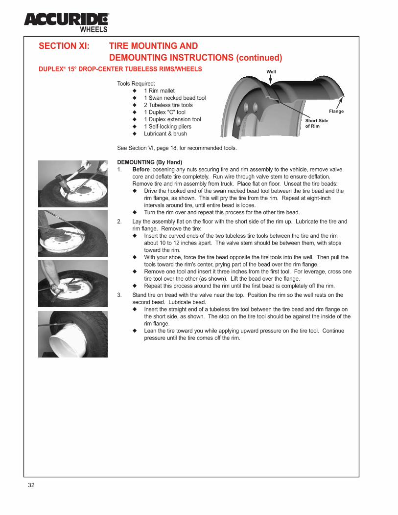
DEMOUNTING INSTRUCTIONS (continued)DUPLEX® 15° DROP-CENTER TUBELESS RIMS/WHEELS
Tools Required:
◆ 1 Rim mallet
◆ 1 Swan necked bead tool
◆ 2 Tubeless tire tools
◆ 1 Duplex "C" tool
◆ 1 Duplex extension tool
◆ 1 Self-locking pliers
◆ Lubricant & brush
See Section VI, page 18, for recommended tools.
DEMOUNTING (By Hand)
1. Before loosening any nuts securing tire and rim assembly to the vehicle, remove valve
core and deflate tire completely. Run wire through valve stem to ensure deflation.
Remove tire and rim assembly from truck. Place flat on floor. Unseat the tire beads:
◆ Drive the hooked end of the swan necked bead tool between the tire bead and the
rim flange, as shown. This will pry the tire from the rim. Repeat at eight-inch
intervals around tire, until entire bead is loose.
◆ Turn the rim over and repeat this process for the other tire bead.
2. Lay the assembly flat on the floor with the short side of the rim up. Lubricate the tire and
rim flange. Remove the tire:
◆ Insert the curved ends of the two tubeless tire tools between the tire and the rim
about 10 to 12 inches apart. The valve stem should be between them, with stops
toward the rim.
◆ With your shoe, force the tire bead opposite the tire tools into the well. Then pull the
tools toward the rim's center, prying part of the bead over the rim flange.
◆ Remove one tool and insert it three inches from the first tool. For leverage, cross one
tire tool over the other (as shown). Lift the bead over the flange.
◆ Repeat this process around the rim until the first bead is completely off the rim.
3. Stand tire on tread with the valve near the top. Position the rim so the well rests on the
second bead. Lubricate bead.
◆ Insert the straight end of a tubeless tire tool between the tire bead and rim flange on
the short side, as shown. The stop on the tire tool should be against the inside of the
rim flange.
◆ Lean the tire toward you while applying upward pressure on the tire tool. Continue
pressure until the tire comes off the rim.
Well
Flange
Short Side
of Rim

33
XI
MOUNTING (By Hand)
1. Inspect the tire and rim for any damage. Be sure tire size and rim size match exactly.
2. Install the valve.
◆ Put valve stem with a rubber grommet through valve hole. Be sure it is centered in
the hole and fits snugly.
◆ From opposite side (weather side), screw on washer and nut. Tighten the nut with
wrench until it is snug. Do not over tighten.
3. Mount the first tire bead.
◆ Place rim on floor with short side up. With an approved tire lubricant, using a brush
or swab, lubricate both bead seats of the rim and both tire beads.
◆ Lay the tire on the rim. Clamp the self-locking pliers on the rim flange, 90° (one-quarter
turn) from the valve stem (as shown). Be sure snub side of pliers is toward the tire.
◆ Insert the "C" tool between the tire bead and the rim flange, moving clockwise from
self-locking pliers. Pull the bottom bead into the well opposite the valve. Pry the tire
over the rim flange opposite where the tire is in the well. Repeat this process in small
amounts around the tire.
◆ To mount the last section of tire, remove the pliers. Then pry the last section of tire
over the rim flange. It may be necessary to install the extension on the "C" tool.
4. Mount the second tire bead.
◆ Lubricate second tire bead. Stand on the tire to push a section of the bead over the
flange and into the well.
◆ Place the self-locking pliers, snub side toward tire, 6" to the left of the valve stem.
Insert the curved end of two tubeless tire tools on either side of the pliers with the stop
toward the rim. Pry the tools to work the bead under the pliers.
◆ Moving counterclockwise, insert the curved end of the tire tools, with stop toward rim,
between the tire and the flange. Pull the tire bead into the well opposite the valve.
Pry the tire over the rim flange opposite where the tire is already in the well.
◆ To mount the last section of tire, remove the pliers. Place the tire tools and pry the
last section of the second bead over the flange.
5. Inflate the tire.
◆ Put tire/rim assembly in safety cage or other OSHA-approved restraining device.
Use an extension hose with an air gauge and clip-on air chuck. Stand clear of
the assembly.
◆ Inflate to recommended inflation pressure.
◆ Before removing from safety cage or restraining device - check to see that
the tire beads are properly seated.

34
SECTION XI: TIRE MOUNTING AND
DEMOUNTING INSTRUCTIONS (continued)MACHINE MOUNTING TIRES ON SINGLE PIECE RIMS
If you have a tire changing machine available, you can mount and demount tires much more easily and quickly than you can by
hand. There are several manufacturers making tire changing machines, and each operates a little differently from the others.
The following instructions apply generally to machine tire changing, but you will have to consult the manual that came with the
machine or your employer for exact instructions on using the machine you have. Remember: there are dangers in mounting
and inflating tires no matter what kind of equipment you use. Follow the instructions exactly for the equipment you
have. And always use safety equipment when inflating a tire.
MACHINE MOUNTING FOR LIGHT TRUCK TUBELESS TIRES (SINGLE PIECE WHEELS)
Using the Tire Changing Machine
Below are instructions for a common type of tire changing machine. The machine in your shop may work differently. Always
follow instructions for the type of tire machine you have.
DEMOUNTING
1. Put the tire and wheel assembly over the center post of the machine,
with the short side of the rim up. The valve stem should be toward you.
2. Thread the hold-down cone onto the center post. Make sure it is hand
tight and in the center of the wheel's center hole.
3. Remove the valve core from the valve stem. Release all air.
4. Place the upper bead loosener shoe on the tire next to the rim.
Press down on the foot pedal until both bead looseners push the tire
from the rim.
5. Position the combination tool in alignment with the center post key.
Insert the demounting end of the tool between the tire and rim. Pull the
combination tool to lift the tire bead over the rim.
6. Pull the tool until the slot in the combination tool is completely over the
center post key.
7. Then rotate the combination tool to remove the upper tire bead from the
rim. Lifting up on the tire with the left hand may help demounting.
8. Remove the lower bead from the rim by repeating the process on that
bead.
WARNING: Before working on any tire/rim assembly, be sure you are trained and thoroughly familiar with the
safety guidelines in Section III of this manual. Improper servicing of tire/rim assemblies can lead to serious, even
fatal, accidents for you or others. Follow recommended mounting/demounting procedures carefully.

35
XI
MOUNTING
1. Inspect the tire and rim for any damage. Be sure tire size
and rim size match exactly. Apply an approved lubricant
to the outside of both beads and to the inside of the top
bead.
2. Place the tire over the wheel rim at an angle. Do not force
the bead into the center of the rim.
3. Hook the mounting end of the combination tool over the
rim flange and locate the slot in the tool over the center
post key.
4. Rotate the combination tool clockwise until it contacts the
tire bead. Continue to rotate the tool clockwise until the
lower bead slides into the groove of the combination tool
and into the drop center of the rim/wheel.
5. Push down on the tire with one hand. As the combination
tool rotates, continue to hold the bead in the drop center
with one hand until the entire tire bead slides over the rim
flange.
6. Mount the second bead in the same manner as the
bottom bead.
INFLATING
1. Connect the machine's air chuck to the valve stem. The
automatic inflation on a tire changing machine will work
more efficiently with the valve core removed.
2. Holding the tire with both hands, lift the tire up against the
upper edge of the rim. Be sure the top tire bead is over
the bottom of the valve stem. Press the air pedal very
briefly (less than one second). This should expand the
tire and seal the beads. Repeat this procedure if the
beads are not sealed.
3. When the beads are seated, loosen the hold-down cone
one full turn to allow for expansion as tire inflates. Do not
remove the cone. Re-install the valve core.
4. Reconnect the air chuck and stand out of the trajectory
(danger zone) to inflate the tire. Release pedal to read tire
pressure. Depress the air pedal in short intervals,
checking the tire pressure each time.
DO NOT INFLATE TIRE TO MORE THAN 40 PSI TO SEAT
THE BEADS. If beads have not seated by 40 psi, remove the
air and relubricate the beads. Check to be sure tire and rim size match and there is no interference between tire and rim.
5. Inflate to recommended pressure. Check for complete beat seating before loosening hold-down cone and taking tire off
machine.
WARNING: NEVER INFLATE A TIRE AND RIM ASSEMBLY THAT IS NOT RESTRAINED. Serious injury can
result from improper inflation. Be sure the hold-down cone is securely holding the assembly. Use a clip-on air
chuck and stand aside during inflation. Do not inflate to more than 40 psi to seat the beads. Do not remove tire/rim
assembly from machine until you are sure the beads are fully seated and the tire is inflated to no more than the
recommended air pressure.
36
SECTION XI: TIRE MOUNTING AND
DEMOUNTING INSTRUCTIONS (continued)
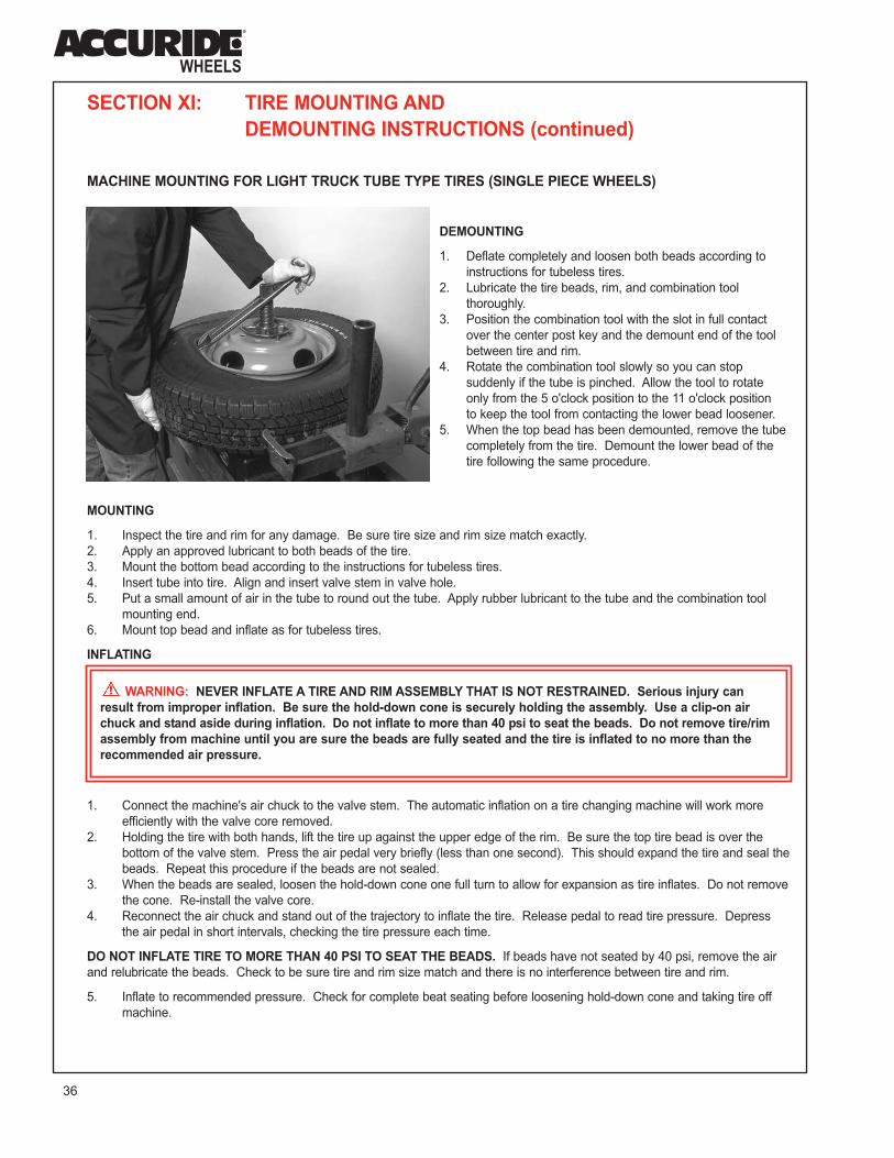
MACHINE MOUNTING FOR LIGHT TRUCK TUBE TYPE TIRES (SINGLE PIECE WHEELS)
DEMOUNTING
1. Deflate completely and loosen both beads according to
instructions for tubeless tires.
2. Lubricate the tire beads, rim, and combination tool
thoroughly.
3. Position the combination tool with the slot in full contact
over the center post key and the demount end of the tool
between tire and rim.
4. Rotate the combination tool slowly so you can stop
suddenly if the tube is pinched. Allow the tool to rotate
only from the 5 o'clock position to the 11 o'clock position
to keep the tool from contacting the lower bead loosener.
5. When the top bead has been demounted, remove the tube
completely from the tire. Demount the lower bead of the
tire following the same procedure.
MOUNTING
1. Inspect the tire and rim for any damage. Be sure tire size and rim size match exactly.
2. Apply an approved lubricant to both beads of the tire.
3. Mount the bottom bead according to the instructions for tubeless tires.
4. Insert tube into tire. Align and insert valve stem in valve hole.
5. Put a small amount of air in the tube to round out the tube. Apply rubber lubricant to the tube and the combination tool
mounting end.
6. Mount top bead and inflate as for tubeless tires.
INFLATING
1. Connect the machine's air chuck to the valve stem. The automatic inflation on a tire changing machine will work more
efficiently with the valve core removed.
2. Holding the tire with both hands, lift the tire up against the upper edge of the rim. Be sure the top tire bead is over the
bottom of the valve stem. Press the air pedal very briefly (less than one second). This should expand the tire and seal the
beads. Repeat this procedure if the beads are not sealed.
3. When the beads are sealed, loosen the hold-down cone one full turn to allow for expansion as tire inflates. Do not remove
the cone. Re-install the valve core.
4. Reconnect the air chuck and stand out of the trajectory to inflate the tire. Release pedal to read tire pressure. Depress
the air pedal in short intervals, checking the tire pressure each time.
DO NOT INFLATE TIRE TO MORE THAN 40 PSI TO SEAT THE BEADS. If beads have not seated by 40 psi, remove the air
and relubricate the beads. Check to be sure tire and rim size match and there is no interference between tire and rim.
5. Inflate to recommended pressure. Check for complete beat seating before loosening hold-down cone and taking tire off
machine.
WARNING: NEVER INFLATE A TIRE AND RIM ASSEMBLY THAT IS NOT RESTRAINED. Serious injury can
result from improper inflation. Be sure the hold-down cone is securely holding the assembly. Use a clip-on air
chuck and stand aside during inflation. Do not inflate to more than 40 psi to seat the beads. Do not remove tire/rim
assembly from machine until you are sure the beads are fully seated and the tire is inflated to no more than the
recommended air pressure.

37
XI
MACHINE MOUNTING FOR HEAVY TRUCK TIRES
(SINGLE PIECE RIMS/WHEELS), INCLUDING ALUMINUM WHEELS
There is a variety in tire changing machines for large truck tires/wheels. The following information is general instructions for
demounting and mounting a tire by machine. You will have to get proper instructions for the machine you are using. Be sure to
consult the manual for the machine you will be using.
TO DEMOUNT BY MACHINE
1. Remove the valve core from the valve stem. Run a wire through the valve stem to be sure tire is deflated completely.
2. Separate the tire bead from the rim with the tire separator tool, if your machine provides for it. If not, put wheel on
machine and lock. Position tool so flat end can be driven between the tire bead and rim flange. Rotate tire tool to
separate bead from the rim. Separate tire bead on the other side of rim in the same way.
3. Lubricate the tire bead.
4. Insert tool under bead, if necessary using tire iron to lift bead to assist tool insertion. Rotate tire. Pull tire up, and pull
lower bead off the same way.
TO MOUNT BY MACHINE
1. Inspect the tire and rim for any damage. Be sure
tire size and rim size match exactly.
2. Put wheel on machine, short side of the rim out.
Lock the wheel to the machine. Lubricate wheel and
tire bead. Put the tire on the wheel, pushing the
bead over the flange as far as possible.
3. Insert rotating arm in central hole. Insert the disc of
the mounting tool between the bead and the rim
flange. Rotate the arm to mount the tire over the
flange, leaning on the tire to help button the bead
beneath the flange.
4. If your machine does not mount both beads at once,
start second bead into the well. Insert tool and
rotate machine to mount bead in the same way you
mounted the first bead.
5. Inflate the tire:
◆ Put tire/rim assembly in safety cage or other
OSHA-approved restraining device. Use an
extension hose with an air gauge and clip-on
air chuck. Stand clear of the assembly.
◆ Inflate to recommended inflation pressure.
◆ Before removing from safety cage or restraining device - check to see that the tire beads are properly seated.

38
SECTION XII: PROCEDURES FOR INSPECTING AND INSTALLING
ACCURIDE RIMS/WHEELS ON VEHICLESHEAVY TRUCK STEEL DISC WHEELS
INSPECTION AND PREPARATION INSTRUCTIONS
■ During Tire Inspections or Periodic Vehicle Maintenance Checks:
◆ Check all metal surfaces thoroughly, including both sides of the
wheels and areas between duals. Watch for excessive rust or
corrosion buildup; cracks in metal; bent, broken flanges or
components; loose, missing, or damaged nuts; bent or stripped
studs; and incorrectly matched rim parts. (See pages 20 through 22.)
◆ Replace an assembly that is damaged or has damaged components.
Remember: Excessively corroded or cracked rims are dangerous,
especially during the removal of the assembly. Deflate tire (both tires
of a dual assembly) before removing the wheel. Insert a wire through
the valve to ensure that debris has not prevented deflation. (See page 4.)
◆ Look for rust streaks which indicate loose nuts or improper nut fit. After tightening
the nuts to the recommended torque level or replacing them, remove the rust streaks.
◆ Replace broken studs and each unbroken stud next to the broken stud.
◆ Determine the cause of the damage before installing another wheel. (See pages 20 through 22.)
◆ Inflate tires to only the recommended air pressure. Be sure not to exceed the wheel's maximum inflation rating. Use
precautions outlined in Section III, Safety Procedures.
■ During Tire Changes (See tire demounting procedures for the type of wheel you have, Section XI):
◆ After the tire is removed, check all metal surfaces, especially the tire side of the rim and the mounting area of the disc.
Watch for the conditions outlined above.
◆ Replace damaged wheels, components, nuts, studs, and valves. Inspect and replace valve grommet as needed.
◆ Completely remove rust, dirt, and other foreign materials from all surfaces. Especially important to clean are the
areas used for mounting the wheel to the vehicle and the rim area where the tire seats. Use hand or electric wire
brushes, light sand blasting, or solvent baths. Wheel mounting areas must be kept flat. Remove any metal
projections, burrs at the bolt hole chamfers, and/or paint build-up. The hub or drum where the wheel contacts must
also be cleaned and kept flat. Wire brush at the base of each stud, on the hub or drum only. The rim bead seat must be clean and
free of rust, corrosion, and rubber deposits to ensure proper tire seating. The gutter of the rim and the rings must be clean to
ensure proper seating of these components. (See page 23.)
◆ Paint or spray all bare metal surfaces of the rim and wheel using a fast-drying metal primer. Surfaces should be clean
and dry prior to painting. Ensure that bare metal areas on the tire side of rim are painted. This is especially
important for tubeless rims, since moisture in the air chamber can cause corrosion. The wheel mounting areas must
be kept free of paint runs and paint buildup. The disc wheel mounting area and the bolt hole chamfers should not
have excessive paint buildup. (See page 23.)
◆ Use the proper tire and rim combination. (See page 25.)
◆ Lubricate tire side of rim base and tire beads just prior to mounting tire. Avoid the use of any lubricant or solvent that is injurious to
rubber, steel, or paint. A combination lubricant and rust-preventive compound is preferable. (See page 8.) The air supply should
incorporate moisture traps to prevent water or moisture inside the tire. Follow the tire mounting instructions for the type of rim
being used. These are in Section XI of this manual.
■ Special Note for ProSteel™ Wheels:
◆ Because of the premium finish of the ProSteel wheel, additional care is necessary to help maintain its attractive appearance.
◆ Do not sand or use a wire brush on appearance surfaces. See page 43.
◆ During tire mounting, handling, and wheel installation, care should be taken to protect the wheel’s coating. Special tools designed to
prevent damage to the wheel are available from tire mounting machine manufacturers. If tires are mounted by hand, rubber mats
or floor pads should be used to protect the disc from scratching or scuffing.
WARNING: Improper parts and incorrect installation procedures could cause a wheel to fail in service. A serious, even fatal,
accident could result. Follow all instructions for inspecting and installing rims/wheels. Do not substitute parts.
Remember:
➡ Wheels must be mounted with the required studs. Stud types are not interchangeable.➡ Always use hub mount wheels and flange nuts on hub mount hubs and stud mount wheels and
chamfered nuts on stud mount hubs. Mixing designs causes premature wheel failure.➡ Nuts must be retorqued routinely. Use the proper nut torque and tightening sequence. ➡ Each tire, wheel, and axle has its own maximum rating. Do not load and inflate the tire/wheel/axle
system beyond the rating of the lowest rated component.➡ Wheels must be mounted on hubs and drums with proper contact surface.➡ The wheel contact surface must be 360 degrees and have the proper diameter to support the wheel.
Tire Side of Rim
Wheel Mounting Area

39
XII
INSTALLATION PROCEDURE
STUD PILOTED MOUNTING
Wheels with the stud piloted mounting system are often called stud mount wheels. Stud piloted wheels are designed to be
centered by the nuts on the studs. The seating action of the chamfered nuts in the chamfered bolt holes centers the wheels.
(See Figure 1.)
■■ 10 Hole, 11¼" Bolt Circle DCN (Double Cap Nut) Mounting
1. Inflate Tire Before Installing on Vehicle. See inflation procedure, pages 8 and 16.
2. Inspect Parts Before Installing. See page 20 through 22 .
◆ Check all parts for damage, including rims/wheels and rings. Ensure that studs, nuts, and mounting faces of hub
drum and wheels are flat, clean, and free of grease. Clean hub surface with wire brush if scale is present. Install
wheels only on hubs or drums that have the proper back-up diameter. (For more information, see SAE J694.)
◆ Replace any damaged parts. Do not bend, weld, heat, or braze components. Do not use tubes to stop rim air
leakage.
◆ Use correct nuts. Inspect nuts to ensure they are not worn and function properly. The nuts listed below are
recommended for use with Accuride and Extra Service Wheels with .875" spherical bolt hole chamfers.
(Manufacturer's part numbers are listed with each figure.)
Typical Front Cap Nut
Figure 1
Typical Inner Cap
Nut For DualsFigure 2
Typical Front or
Outer Cap NutFigure 3
3/4"-16 Thread
Right Left
X-1803 X-1804
E-5652R E-5652L
3/4"-16 Thread
Right Left
X-1828 X-1829
E-7895R E-7895L
1 1/8"-16 Thread
Right Left
X-1831 X-1832
E-5977R E-5977L
Figure 4 Figure 5 Figure 6 Figure 7
RECOMMENDED ASSEMBLIES
IMPROPER ASSEMBLIES
The inner cap nuts above or
their equivalent must not be
used for wheels in single
applications due to limited
nut to disc contact.
Flanged cap nuts shown
above or their equivalent,
are not recommended to be
used since the nut will not
contact the bolt hole
chamfer and slippage may
occur.
The nuts shown above or their equivalent are special for
aluminum wheels only and must not be used to install steel
wheels since bottoming may occur (Arrow A) before nuts
are seated (Arrow B).
B
A
B
A
Key to Nut Sources: X - National Wheel and Rim Association, Jacksonville, FL
E - Euclid Industries, Inc., Cleveland, OH

40
SECTION XII: PROCEDURES FOR INSPECTING AND INSTALLING
ACCURIDE RIMS/WHEELS ON VEHICLES (continued)
STUD PILOTED MOUNTING (continued)
3. Install Wheel on Vehicle.
◆ Front Wheels
Slide front wheel over studs. Be careful not to damage
the stud threads. Snug up nuts in the sequence
shown in Figure 8. Do not tighten them fully until all
have been seated. This procedure will permit the
uniform seating of nuts and ensure the even, face-to-
face contact of wheels, hub, and drum. Tighten nuts
to 450-500 ft.-lbs. (dry) using the same criss-cross
sequence.
◆ Dual Rear Wheels
Slide the inner dual wheel over studs. Be careful not to
damage the stud threads. Snug up nuts in the sequence
shown in Figure 8. Do not tighten them fully until all have
been seated. This procedure will permit the uniform
seating of nuts and ensure the even, face-to-face contact
of wheels, hub, and drum. Tighten nuts to 450-500 ft.-lbs.
(dry) using the same criss-cross sequence.
Align the hand holes of the outer dual wheel to those of
the inner dual wheel to allow access to the air valves.
Slide the outer dual wheel over the inner cap nuts.
Repeat the entire procedure except using the nut
tightening sequence in Figure 8. Tighten the outer
cap nut to 450-500 ft.-lbs.
4. Torque Nuts Properly.
◆ Be sure to tighten wheel nuts to the recommended nut torque. Do not over tighten. Do not lubricate the nuts or studs.
◆ After the first 50 to 100 miles of operation, recheck the torque level and retighten nuts to the proper torque level.
Before inner cap nuts are retightened, be sure to loosen the outer cap nuts first, tighten inner cap nuts, and then
retighten outer cap nuts to proper torque level.
◆ Maintain nut torque at the recommended level through planned, periodic checks or at 10,000 mile intervals, whichever
comes first. Individual fleet experience may dictate shorter intervals or allow longer intervals.
◆ If air wrenches are used, they must be periodically calibrated for proper torque output. Use a torque wrench to check
the air wrench output and adjust the line pressure to give correct torque.
■ Other Mounting Patterns
Other stud piloted mounting patterns may use different nuts and stud sizes requiring different nut tightening sequences
and different recommended torque levels. Consult with the wheel manufacturer. Also refer to page 52 for additional
information.
Nut Tightening Sequence
Figure 8
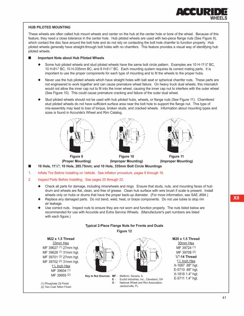
41
XII
HUB PILOTED MOUNTING
These wheels are often called hub mount wheels and center on the hub at the center hole or bore of the wheel. Because of this
feature, they need a close tolerance in the center hole. Hub piloted wheels are used with two-piece flange nuts (See Figure 9),
which contact the disc face around the bolt hole and do not rely on contacting the bolt hole chamfer to function properly. Hub
piloted wheels generally have straight-through bolt holes with no chamfers. This feature provides a visual way of identifying hub
piloted wheels.
■■ Important Note about Hub Piloted Wheels
◆ Some hub piloted wheels and stud piloted wheels have the same bolt circle pattern. Examples are 10 H-11¼" BC,
10 H-83/4" BC, 10 H-335mm BC, and 8 H-61/2" BC. Each mounting system requires its correct mating parts. It is
important to use the proper components for each type of mounting and to fit the wheels to the proper hubs.
◆ Never use the hub piloted wheels which have straight holes with ball seat or spherical chamfer nuts. These parts are
not engineered to work together and can cause premature wheel failure. On heavy truck dual wheels, this mismatch
would not allow the inner cap nut to fit into the inner wheel, causing the inner cap nut to interfere with the outer wheel
(See Figure 10). This could cause premature cracking and failure of the outer dual wheel.
◆ Stud piloted wheels should not be used with hub piloted hubs, wheels, or flange nuts (See Figure 11). Chamfered
stud piloted wheels do not have sufficient surface area near the bolt hole to support the flange nut. This type of
mis-assembly may lead to loss of torque, broken studs, and cracked wheels. Information about mounting types and
sizes is found in Accuride's Wheel and Rim Catalog.
■■ 10 Hole, 11¼"; 10 Hole, 285.75mm; and 10 Hole, 335mm Bolt Circle Mountings
1. Inflate Tire Before Installing on Vehicle. See inflation procedure, pages 8 through 16.
2. Inspect Parts Before Installing. See pages 20 through 22.
◆ Check all parts for damage, including rims/wheels and rings. Ensure that studs, nuts, and mounting faces of hub
drum and wheels are flat, clean, and free of grease. Clean hub surface with wire brush if scale is present. Install
wheels only on hubs or drums that have the proper back-up diameter. (For more information, see SAE J694.)
◆ Replace any damaged parts. Do not bend, weld, heat, or braze components. Do not use tubes to stop rim
air leakage.
◆ Use correct nuts. Inspect nuts to ensure they are not worn and function properly. The nuts listed below are
recommended for use with Accuride and Extra Service Wheels. (Manufacturer's part numbers are listed
with each figure.)
Figure 9
(Proper Mounting)
Figure 10
(Improper Mounting)
Figure 11
(Improper Mounting)
M22 x 1.5 Thread
33mm Hex
MF 39627 (1) 27mm hgt.
MF 39628 (1) 31mm hgt.
MF 39701 (2) 27mm hgt.
MF 39702 (2) 31mm hgt.
11/2 Inch Hex
MF 39604 (1)
MF 39955 (2)
M20 x 1.5 Thread
30mm Hex
MF 39724 (1)
MF 39708 (2)
7/8"-14 Thread
11/2 Inch Hex
X-1687 .88" hgt.
E-5710 .88" hgt.
X-1818 1.4" hgt.
E-5711 1.4" hgt.
Typical 2-Piece Flange Nuts for Fronts and Duals
Figure 12
(1) Phosphate Oil Finish
(2) Two Coat Teflon Finish
Key to Nut Sources: MF - Metform, Savana, IL
E - Euclid Industries, Inc., Cleveland, OH
X - National Wheel and Rim Association,
Jacksonville, FL

42
SECTION XII: PROCEDURES FOR INSPECTING AND INSTALLING
ACCURIDE RIMS/WHEELS ON VEHICLES (continued)
HUB PILOTED MOUNTING (continued)
◆ Before reusing flange nuts that have
already been used in service, apply
2 drops of 30 weight oil at one point
between the flange and the hex.
This will allow the parts to rotate freely
and provide the proper clamping force
when tightened. (See Figure 13.)
Excessive lubricant is not desirable. It
will not improve nut performance. And it
makes the nuts hard to handle, attracts
dirt to the nuts, and may cause unsightly
appearance to the wheel. Only used
nuts need to be lubricated.
◆ Since flange nuts generate higher
clamping force, always use grade eight
studs with hub mount wheels.
3. Install Wheel on Vehicle.
◆ Before installing wheels, lubricate the hub pilot pads or the hub bore of the wheel with a non-water based lubricant
which contains a corrosion inhibitor. Also, apply two drops of oil to the last two or three threads at the end of each
stud. Do not lubricate any other wheel or hub surfaces.
◆ For a hub with intermittent pilot pads, position a pad at 12 o'clock to center the wheel and reduce runout.
■■ Front Wheels
Slide the front wheel over studs being careful not to damage the stud threads. Snug up nuts in the sequence shown in
Figure 8 on page 40. Do not tighten them fully until all have been seated. Tighten nuts to hold 450 to 500 ft.-lbs. using
the same criss-cross sequence.
■■ Dual Rear Wheels
Slide the inner dual wheel over the studs being careful not to damage the stud threads. Align the hand holds for valve
access and slide the outer dual wheel over the studs, again being careful not to damage the stud threads.
Snug up nuts in the sequence shown for outer duals in Figure 8 on page 40. Do not tighten them fully until all have
been seated. Tighten nuts to 450 to 500 ft.-lbs. (for M22 x 1.5 studs) using the same sequence. Hub mount wheels use
two-piece flange cap nuts for both the front and rear applications. No inner cap nuts are required.
4. Torque Nuts Properly.
◆ Be sure to tighten wheel nuts to the recommended nut torque. Do not over tighten.
◆ After the first 50 to 100 miles of operation, recheck the torque level and retighten nuts to the proper torque level.
◆ Maintain nut torque at the recommended level through planned, periodic checks or at 10,000 mile intervals, whichever
comes first. Individual fleet experience may dictate shorter intervals or allow longer intervals.
◆ If air wrenches are used, they must be periodically calibrated for proper torque output. Use a torque wrench to check
the air wrench output and adjust the line pressure to give correct torque.
Figure 13

43
XII
■■ 8 Hole, 275mm Bolt Circle Mounting
Follow the same general installation guidelines as for the 10-Hole, 285.75mm bolt circle mounting, but use the nut
tightening sequence shown in Figure 14. Tighten the nuts to the recommended nut torque values on page 52.
■■ Other Mounting Patterns
Other hub piloted mounting patterns may use different nuts and stud sizes. These may require a different nut tightening
sequence and different recommended torque values. Consult with the wheel manufacturer. Also refer to page 52 for
additional information.
■■ Care and Maintenance of ProSteel™ Wheels
◆ The ProSteel wheel can be easily cleaned with high-pressure water from a hose. The use of a mild detergent will
speed the cleaning process. Do not use harsh alkaline or acid cleaners. Secondary hand washing with a soft cloth
may be required to remove some stubborn road films.
◆ For added protection, you may use a high-quality, nonabrasive polish.
◆ Clean the wheels on a routine basis as determined by usage.
◆ If paint is chipped, thereby exposing steel, the area should be touched up as soon as possible. (Note: Refinishing
ProSteel wheels requires a special process and should only be done by qualified technicians.)
◆ For further protection, and to validate the 2-year warranty on the ProSteel wheel finish, the Wheel-Guard®
separator plate must be used between all mating surfaces of the wheel. The Wheel-Guard® separator plate
should be used between the hub and the wheel and between dual wheels. This will prevent disc wear and scratching.
For questions on touch-up procedures and for more information regarding the care and maintenance of ProSteel wheels,
contact Accuride Field Engineering at 1-800-869-2275.
Figure 14
Nut Tightening Sequence

44
SECTION XII: PROCEDURES FOR INSPECTING AND INSTALLING
ACCURIDE RIMS/WHEELS ON VEHICLES (continued)
HEAVY TRUCK ALUMINUM WHEELS
INSPECTION AND PREPARATION INSTRUCTIONS
■ During Tire Inspections or Periodic Vehicle Maintenance Checks:
◆ Check all metal surfaces thoroughly including both sides of the wheels and areas between duals. Watch for
excessive corrosion buildup; cracks in metal; bent, broken flanges; loose, missing, or damaged nuts; bent or stripped
studs. (See pages 20 through 22.)
◆ Replace an assembly that is damaged. Remember: Excessively corroded or cracked rims are dangerous, especially
during the removal of the assembly. Deflate tire (both tires of a dual assembly) before removing the wheel. Insert a
wire through the valve to ensure that debris has not prevented deflation. (See page 4.)
◆ Look for corrosion streaks which are an indication of loose nuts or improper nut fit. After tightening the nuts to the
recommended torque level or replacing them, remove the rust streaks.
◆ Replace broken studs and each unbroken stud next to the broken stud.
◆ Determine the cause of the damage before installing another wheel. (See pages 20 through 22.)
◆ Inflate tires to only the recommended air pressure. Be sure not to exceed the wheel's maximum inflation rating.
Use precautions outlined in Section III, Safety Procedures.
WARNING: Improper parts and incorrect installation procedures could cause a wheel to fail in service.
A serious, even fatal, accident could result. Follow all instructions for inspecting and installing rims/wheels.
Do not substitute parts. Remember:
➡ Wheels must be mounted with the required studs. Stud types are not interchangeable.➡ Always use hub mount wheels and flange nuts on hub mount hubs and stud mount wheels and
chamfered nuts on stud mount hubs. Mixing designs causes premature wheel failure.➡ Nuts must be retorqued routinely. Use the proper nut torque and tightening sequence. ➡ Each tire, wheel, and axle has its own maximum rating. Do not load and inflate the tire/wheel/axle
system beyond the rating of the lowest rated component.➡ Wheels must be mounted on hubs and drums with proper contact surface.➡ The wheel contact surface must be 360 degrees and have the proper diameter to support the wheel.
Tire Side of Rim
Wheel Mounting Area
45
XII
■■ During Tire Changes (See tire demounting procedures for the type of wheel you have, Section XI):
◆ After the tire is removed, check all metal surfaces, especially the tire side of the rim, the rim flanges, and the mounting
area of the disc. Watch for the conditions previously outlined.
◆ Replace damaged wheels, components, nuts, studs, and valves. Inspect and replace valve grommet as needed.
When replacing valves, apply anti-corrosive compound (such as Frey-Lube II) around the valve hole on the tire side of
tubeless aluminum wheels. The valve nut should be torqued to 125 in.-lbs.
◆ Completely remove corrosion, dirt, and other foreign materials from all surfaces. It is especially important to clean the
areas used for mounting the wheel to the vehicle and the rim area where the tire seats. Use a wire brush or
sandpaper. Take care when cleaning the appearance surface on the wheel disc. Do not sand or use a wire brush on
this surface. (See page 47.)
Wheel mounting areas must be kept flat. Remove any metal projections or burrs at the bolt hole chamfers. The hub
or drum where the wheel contacts it must also be cleaned and kept flat. Wire brush at the base of each stud on the
hub or drum only. The rim bead seat must be clean and free of corrosion and rubber deposits to ensure proper tire
seating. (See page 23.) A thin coating of an anti-corrosive compound (such as Frey-Lube II) can be used as a rim
surface protectant. Paint is not required or recommended for aluminum wheels.
◆ Use the proper tire and rim combination. (See page 25.)
◆ Since the decorative surface of aluminum wheels can be scratched during tire mounting, use a rubber mat or floor
pad on the floor. Use extra care during tire mounting. Do not use tire mounting machines that clamp to the inside of
the rim, as the clamps may severely gouge the rim. Special tire changer adapters are available. Use one if necessary.
◆ Lubricate tire side of rim base and tire beads just before mounting tire. Avoid the use of any lubricant or solvent that
is injurious to rubber or aluminum. A combination lubricant and corrosion-preventive compound is preferable. (See
page 8.) The air supply should incorporate moisture traps to prevent water or moisture inside the tire. Follow the
tire mounting instructions for tubeless rims on page 29.
■■ Special Note for ACCU-SHIELD™ Aluminum Wheels
◆ Because of the finish of the ACCU-SHIELD wheel, additional care is necessary to help maintain the attractive
appearance of these wheels. (See page 47.)
◆ During tire mounting, handling, and wheel installation, care should be taken to protect the finish on the wheel.
Special tools are available from manufacturers of tire mounting machines which are designed to prevent damage to
the wheel. These tools may be made from special materials or have special coatings which prevent marring, scuffing,
and other damage to the surface of the wheel.
WARNING: Excessive heat from fire, brake malfunction, wheel bearing failure, or other sources may
weaken the metal and cause the wheel/tire assembly to fail in service. A serious, even fatal accident could
result. Immediately and permanently remove from service any wheel that has been exposed to excessive heat.

46
SECTION XII: PROCEDURES FOR INSPECTING AND INSTALLING
ACCURIDE RIMS/WHEELS ON VEHICLES (continued)
INSTALLATION PROCEDURE
The procedures used to install aluminum wheels on a vehicle are identical to those of heavy truck steel disc wheels on pages 39
through 43, except for the nuts used. Accuride aluminum wheels have a thicker disc than conventional steel wheels. Therefore,
special nuts and longer studs may be required.
STUD PILOTED MOUNTING
■ 10 Hole, 11¼" Bolt Circle DCN (Double Cap Nut) Mounting
Front Wheels
◆ For 11/8" -16 studs, use standard heavy truck steel disc wheel front or outer nuts. (See Figure 15.) If you are making
a changeover from steel wheels, longer studs may be necessary to ensure that the stud is at least flush or extends
through the nut.
◆ For 3/4" - 16 studs, special cap nuts with a collar must be used. (See Figure 16.)
Rear Dual Wheels
◆ Special inner cap nuts with a collar must be used with aluminum wheels. (See Figure 17 on page 47.)
◆ For aluminum wheels, the recommended stud or bolt stand-out beyond the mounting face of the hub or outboard
drum is 15/16" to 17/16" (same as for steel wheels). With this stand-out, the mechanical properties of the special inner
cap nut must be equivalent to SAE Grade 8.
◆ For vehicles now in service with long studs (13/4" to 17/8" stand-out), SAE Grade 5 inner cap nuts may be used
provided they are designed to accept the long stud length. The longer stud is generally not recommended because
with steel wheels the inner cap nut will bottom out internally on the longer stud before sufficient contact is made with
the wheel bolt hole chamfer.
◆ When stud piloted wheels are run as a single on rear axles, use front cap nuts instead of inner cap nuts.
Typical Front or
Outer Cap Nut
11/8"-16 Thread
Right Left
X-1831 X-1832
E-5977R E-5977L 7/8" hgt.
E-5996R E-5996L 1" hgt.
Typical Front Cap Nut
Used For Aluminum Wheels3/4"-16 Thread
Right Left
X-1807 X-1808
E-5554R E-5554L
Figure 15 Figure 16
Key to Nut Sources: X - National Wheel and Rim Association, Jacksonville, FL
E - Euclid Industries, Inc., Cleveland, OH
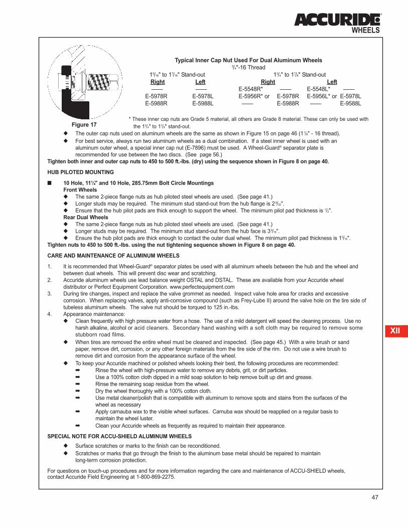
47
XII
◆ The outer cap nuts used on aluminum wheels are the same as shown in Figure 15 on page 46 (11/8" - 16 thread).
◆ For best service, always run two aluminum wheels as a dual combination. If a steel inner wheel is used with an
aluminum outer wheel, a special inner cap nut (E-7896) must be used. A Wheel-Guard® separator plate is
recommended for use between the two discs. (See page 56.)
Tighten both inner and outer cap nuts to 450 to 500 ft.-lbs. (dry) using the sequence shown in Figure 8 on page 40.
HUB PILOTED MOUNTING
■ 10 Hole, 11¼" and 10 Hole, 285.75mm Bolt Circle Mountings
Front Wheels
◆ The same 2-piece flange nuts as hub piloted steel wheels are used. (See page 41.)
◆ Longer studs may be required. The minimum stud stand-out from the hub flange is 29/32".
◆ Ensure that the hub pilot pads are thick enough to support the wheel. The minimum pilot pad thickness is 1/2".
Rear Dual Wheels
◆ The same 2-piece flange nuts as hub piloted steel wheels are used. (See page 41.)
◆ Longer studs may be required. The minimum stud stand-out from the hub face is 33/16".
◆ Ensure the hub pilot pads are thick enough to contact the outer dual wheel. The minimum pilot pad thickness is 15/16".
Tighten nuts to 450 to 500 ft.-lbs. using the nut tightening sequence shown in Figure 8 on page 40.
CARE AND MAINTENANCE OF ALUMINUM WHEELS
1. It is recommended that Wheel-Guard® separator plates be used with all aluminum wheels between the hub and the wheel and
between dual wheels. This will prevent disc wear and scratching.
2. Accuride aluminum wheels use lead balance weight OSTAL and DSTAL. These are available from your Accuride wheel
distributor or Perfect Equipment Corporation. www.perfectequipment.com
3. During tire changes, inspect and replace the valve grommet as needed. Inspect valve hole area for cracks and excessive
corrosion. When replacing valves, apply anti-corrosive compound (such as Frey-Lube II) around the valve hole on the tire side of
tubeless aluminum wheels. The valve nut should be torqued to 125 in.-lbs.
4. Appearance maintenance:
◆ Clean frequently with high pressure water from a hose. The use of a mild detergent will speed the cleaning process. Use no
harsh alkaline, alcohol or acid cleaners. Secondary hand washing with a soft cloth may be required to remove some
stubborn road films.
◆ When tires are removed the entire wheel must be cleaned and inspected. (See page 45.) With a wire brush or sand
paper, remove dirt, corrosion, or any other foreign materials from the tire side of the rim. Do not use a wire brush to
remove dirt and corrosion from the appearance surface of the wheel.
◆ To keep your Accuride machined or polished wheels looking their best, the following procedures are recommended:
➡ Rinse the wheel with high-pressure water to remove any debris, grit, or dirt particles.
➡ Use a 100% cotton cloth dipped in a mild soap solution to help remove built up dirt and grease.
➡ Rinse the remaining soap residue from the wheel.
➡ Dry the wheel thoroughly with a 100% cotton cloth.
➡ Use metal cleaner/polish that is compatible with aluminum to remove spots and stains from the surfaces of the
wheel as necessary
➡ Apply carnauba wax to the visible wheel surfaces. Carnuba wax should be reapplied on a regular basis to
maintain the wheel luster.
➡ Clean your Accuride wheels as frequently as required to maintain their appearance.
SPECIAL NOTE FOR ACCU-SHIELD ALUMINUM WHEELS
◆ Surface scratches or marks to the finish can be reconditioned.
◆ Scratches or marks that go through the finish to the aluminum base metal should be repaired to maintain
long-term corrosion protection.
For questions on touch-up procedures and for more information regarding the care and maintenance of ACCU-SHIELD wheels, contact Accuride Field Engineering at 1-800-869-2275.
Typical Inner Cap Nut Used For Dual Aluminum Wheels3/4"-16 Thread
15/16" to 17/16" Stand-out 13/4" to 17/8" Stand-out
Right Left Right Left
—— —— E-5548R* —— E-5548L* ——
E-5978R E-5978L E-5956R* or E-5978R E-5956L* or E-5978L
E-5988R E-5988L —— E-5988R —— E-9588L
Figure 17* These inner cap nuts are Grade 5 material, all others are Grade 8 material. These can only be used with
the 13/4" to 17/8" stand-out.

48
SECTION XII: PROCEDURES FOR INSPECTING AND INSTALLING
ACCURIDE RIMS/WHEELS ON VEHICLES (continued)
DUPLEX® RIMS/WHEELS FOR WIDE BASE TIRES
INSPECTION AND PREPARATION INSTRUCTIONS FOR DUPLEX® DEMOUNTABLE RIMS
■■ During Tire Inspections or Periodic Vehicle Maintenance Checks:
The inspection and preparation procedure is identical to that for demountable rims shown on page 53.
■■ During Tire Changes:
The inspection and preparation procedure is identical to that for demountable rims shown on pages 53 and 54.
INSTALLATION PROCEDURE FOR DUPLEX DEMOUNTABLE RIMS
The procedure used to install Duplex demountable rims on a vehicle are identical to those for demountable rims on pages 54
and 55.
INSPECTION AND PREPARATION INSTRUCTIONS FOR DUPLEX STEEL DISC WHEELS
■■ During Tire Inspections or Periodic Vehicle Maintenance Checks:
The inspection and preparation procedure is identical to that for heavy truck steel disc wheels shown on page 38.
■■ During Tire Changes:
The inspection and preparation procedure is identical to that for heavy truck steel disc wheels shown on page 38.
INSTALLATION PROCEDURE FOR DUPLEX STEEL DISC WHEELS
The procedure used to install Duplex wheels on a vehicle are identical to those for heavy truck steel disc wheels on pages 39
through 43. Duplex wheels have a thicker disc than conventional steel disc wheels. Deeper chamfers are provided so that
standard studs may be used.
WARNING: Improper parts and incorrect installation procedures could cause a wheel to fail in service. A serious, even fatal,
accident could result. Follow all instructions for inspecting and installing rims/wheels. Do not substitute parts. Remember:
➡ Wheels must be mounted with the required studs. Stud types are not interchangeable.➡ Always use hub mount wheels and flange nuts on hub mount hubs and stud mount wheels and
chamfered nuts on stud mount hubs. Mixing designs causes premature wheel failure.➡ Nuts must be retorqued routinely. Use the proper nut torque and tightening sequence. ➡ Each tire, wheel, and axle has its own maximum rating. Do not load and inflate the tire/wheel/axle
system beyond the rating of the lowest rated component.➡ Wheels must be mounted on hubs and drums with proper contact surface.➡ The wheel contact surface must be 360 degrees and have the proper diameter to support wheel.➡ The rim must be mounted on spoke wheels with proper contact area.

49
XII
STUD PILOTED MOUNTING
■■ 10 Hole, 111/4" Bolt Circle DCN Mounting
Duplex wheels, with regular chamfers, use
the same nuts (see Figure 18) and have the
same installation procedure as for heavy
truck steel disc wheels shown on pages 38
and 43.
■■ 10 Hole, 133/16" Bolt Circle (HD) Mounting
Duplex wheels with this mounting pattern
have a heavy duty (HD) mounting. This
mounting has different bolt hole chamfers
(13/16") and requires special nuts with this
same chamfer (13/16"). These nuts are shown
in Figure 19. Use the same tightening
procedure described on page 40 (Figure 8),
but the final torque value should be 750 to
900 ft.-lbs. (dry).
■■ Duplex wheels have special deep
countersinks. The proper nuts must be
used. (See page 39 for examples of
improper assemblies.)
HUB PILOTED MOUNTING
■■ 10 Hole, 285.75mm Bolt Circle Mounting
Duplex wheels use the same nuts (see
Figure 20) and have the same installation
procedure as for heavy truck steel disc wheels
shown on pages 38 and 43.
WARNING: Not all nuts and studs can be used with all types of wheels. The use of improper nuts and studs
can cause nut loosening, stud failure or premature wheel failure, which could cause an accident or injury. The
offset of Duplex wheels can affect the loading on the axle ends. When retrofitting trailers with wheels having an
outset greater than .63 inches, consult the axle manufacturer.
Typical Outer Cap Nut
11/8"-16 Thread3/4"-16 Thread 11/8"-16 Thread
Right Left Right Left
X-1803 X-1804 X-1831 X-1832
E-5652R E-5652L E-5977R 7/8" hgt. E-5977L
E-5996R 1" hgt. E-5996L
Typical Heavy Duty (HD) Outer Cap Nut15/16"-12 Thread 15/16"-12 Thread
Right Left Right Left
X-1644 X-1645 X-1416 X-1417
E-5863R E-5863L E-5576R E-5576L
13/16"-12 Thread 11/8"-16 Thread
Right Left Right Left
X-1414 X-1415 X-1362 X-1363
E-5577R E-5577L E-6060R E-6060L
Typical 2-Piece Flange Nut
M22 x 1.5 Thread
33mm Hex
MF 39627(1) 27mm hgt.
MF 39628(1) 31mm hgt.
MF 39701(2) 27mm hgt.
MF 39702(2) 31mm hgt.
11/2" Inch Hex
MF 39604(1)
MF 39955(2)
(1) Phosphate Oil Finish
(2) Two Coat Teflon Finish
Key to Nut Sources:
X - National Wheel and Rim Association,
Jacksonville, FL
E - Euclid Industries, Inc., Cleveland, OH
MF - Metform, Savana, IL
Figure 18
Figure 19
Figure 20

50
SECTION XII: PROCEDURES FOR INSPECTING AND INSTALLING
ACCURIDE RIMS/WHEELS ON VEHICLES (continued)LIGHT AND MEDIUM TRUCK STEEL DISC WHEELS
INSPECTION AND PREPARATION INSTRUCTIONS
■■ During Tire Inspections or Periodic Vehicle Maintenance Checks:
The inspection and preparation procedure is identical to that for heavy truck steel disc wheels shown on page 38.
■■ During Tire Charges:
The inspection and preparation procedure is identical to that for heavy truck steel disc wheels shown on page 38.
INSTALLATION PROCEDURE
The procedure used to install light and medium wheels on a vehicle are identical to those for heavy truck steel disc wheels on
pages 39 through 43, except for the nut tightening sequence and recommended torque levels
STUD PILOTED MOUNTING
■■ 6 Hole, 83/4" Bolt Circle DCN Mounting
Use the tightening sequence shown in Figure 21. For 3/4"-16 and 11/8"-16 studs, tighten the inner and outer cap nuts to
450-500 ft.-lbs. torque (dry)
■■ 8 Hole, 61/2" Bolt Circle Mounting
◆ Light Truck Single Wheel
➡ For 9/16"-18 studs, tighten the nuts to 130-150 ft.-lbs. torque (dry) using the sequence shown in Figure 22.
WARNING: Not all nuts and studs can be used with all types of wheels. The use of improper nuts and studs
can cause nut loosening, stud failure, or premature wheel failure, which could cause an accident or injury.
Nut Tightening Sequence
Figure 21
Nut Tightening Sequence
Figure 2260° cone nuts 90° cone nuts
WARNING: Improper parts and incorrect installation procedures could cause a wheel to fail in service. A
serious, even fatal, accident could result. Follow all instructions for inspecting and installing rims/wheels. Do not substitute
parts. Remember:
➡ Wheels must be mounted with the required studs. Stud types are not interchangeable.➡ Always use hub mount wheels and flange nuts on hub mount hubs and stud mount wheels and
chamfered nuts on stud mount hubs. Mixing designs causes premature wheel failure.➡ Nuts must be retorqued routinely. Use the proper nut torque and tightening sequence. ➡ Each tire, wheel, and axle has its own maximum rating. Do not load and inflate the tire/wheel/axle
system beyond the rating of the lowest rated component.➡ Wheels must be mounted on hubs and drums with proper contact surface.➡ The wheel contact surface must be 360 degrees and have the proper diameter to support wheel.

51
XII
◆ In-Out Coined Dual Wheels:
➡ With 90° cone nuts 9/16"-18, (X-1146,7) or 5/8"-18, (X-1148,9), use the tightening sequence shown with
Figure 23. The nuts should be tightened to 175-200 ft.-lbs. torque (dry).
➡ With flanged cap nuts 5/8"-18 (Budd Nut Part No. 95188,9), use the tightening sequence shown with Figure 24.
The nuts should be tightened to 275-325 ft.-lbs. torque (dry).
■ Other Mounting Patterns
Other stud-piloted mounting patterns may use different nuts and stud sizes which require different nut tightening
sequences and different recommended torque levels. Consult with the wheel manufacturer. Also refer to page 52 for
additional information.
HUB PILOTED MOUNTING
■ 8 hole, 170 MM Bolt Circle, and 8 Hole, 225 MM Bolt Circle Mountings
◆ Before Installing the wheel:
1. Lubricate the first 1" of each stud using a shop towel moistened with 30 weight motor oil.
2. Apply two drops of 30 weight motor oil to the one point between the flange and the hex of the flange nuts (See
Figure 13 on page 42).
3. Apply a thin film of a corrosion preventative grease to the hub bore of the wheel.
◆ Use Nut tightening sequence shown with Figure 25. Tighten nuts to the recommended nut torque valves on page 52.
■ 8 Hole, 275mm Bolt Circle Mounting
◆ Use nut tightening sequence shown with Figure 25. Tighten nuts to the recommended nut torque values on page 52.
Nut Tightening Sequence
Nut Tightening Sequence
Figure 23 Figure 24
Figure 25

52
SECTION XII: PROCEDURES FOR INSPECTING AND INSTALLING
ACCURIDE RIMS/WHEELS ON VEHICLES (continued)HUB PILOTED MOUNTING (continued)
■■ 8 Hole, 61/2" Bolt Circle MountingUse nut tightening sequence shown in Figure 25 on page 51. Three nut types can be used with this mounting (see
figures below). Each nut type and size requires a different recommended torque level. Refer to the stud size and nut type
in the recommended nut torque table below.
■■ 10 Hole, 11¼"; 10 Hole, 285.75mm and 10 Hole, 335mm Bolt Circle MountingSee information on pages 41 through 43.
■■ Other Mounting Patterns
Other mounting patterns may use different nuts and studs sizes which require different nut tightening sequence and different
recommended torque levels. Consult the wheel manufacturer.
Recommended Nut Torque
Figure 26
(Hub-Type)
Figure 27
(Hub-Type)
Figure 28
(Hub-Type with
Clamping Plate)
MOUNTINGTHREAD
SIZETORQUE FT.-LBS
NUT TYPE
LIGHT TRUCK
10 Hole, 7.25" Hub-Piloted (Ford) (5.47" Bore) 9/16 - 18 125 - 165 two piece flange
10 Hole, 7.25" Hub-Piloted (Chevy) (5.25" Bore) - with clamping plate 5/8 - 18 171 - 179 90O cone(1) with clamping plate
8 Hole, 6.50" I.O.C. (Ford)9/16 - 18 175 - 200
90O cone5/8 - 18 175 - 200
8 Hole, 6.50" (Chrysler) 9/16 - 18 125 - 165 two piece flange
8 Hole, 6.50" (Chrysler) 5/8 - 18 275 - 325 one piece flange
8 Hole, 6.50" Hub-Piloted (Ford) (4.88" Bore)9/16 - 18 125 - 165 two piece flange
5/8 - 18 130 - 170 two piece flange
8 Hole, 6.50" Stud-Piloted (Ford) (4.88" Bore) - Single Wheel 9/16 - 18 130 - 150 60O cone
8 Hole, 6.50" Hub-Piloted (Chevy) M14 x 1.5 110 - 120 two piece flange
8 Hole, 6.50" Hub-Piloted (Chevy) (4.56" Bore) - with clamping plate9/16 - 18 136 -144
90O cone(1) with clamping plateM14 x 1.5 136 -144
8 Hole, 6.50" Hub-Piloted (Chevy) (4.60" Bore) M14 x 1.5 136 -144 two piece flange
8 Hole, 170mm, Hub-Piloted (Ford) (125.10mm Bore) M14 x 2.0 150 - 160 two piece flange
8 Hole, 225mm, Hub-Piloted (Ford) (170.10mm Bore) M14 x 2.0 150 - 160 two piece flange
6 Hole, 8.75" Stud-Piloted3/4 - 16 450 - 500
.875" spherical radius1 - 1/8 - 16 450 - 500
6 Hole, 225.25mm Stud-Piloted. Japanese .866" Nut Type M20 x 1.5 325 - 400 .866" spherical radius
MEDIUM/HEAVY TRUCK, TRAILER, AND BUS
10 Hole, 13 3/16" HD Stud-Piloted15/16 - 12 750 - 900
1.187" spherical radius1 - 5/16 - 12 750 - 900
10 Hole, 335mm Hub-Piloted M22 x 1.5 450 - 500 two piece flange
10 Hole, 11 1/4" Stud-Piloted3/4 - 16 450 - 500
.875" spherical radius1 - 1/8 - 16 450 - 500
10 Hole, 11 1/4" Hub-Piloted (Bus Mount)3/4 - 16 300 - 350
two piece flange7/8 - 14 350 - 400
10 Hole, 285.75mm Hub-Piloted M22 x 1.5 450 - 500 two piece flange
10 Hole, 8.75" Hub-Piloted 11/16 - 16 300 - 400 one piece flange
10 Hole, 8.75" Stud-Piloted3/4 - 16 450 - 500
.875" spherical radius1 - 1/8 - 16 450 - 500
10 Hole, 200mm Hub-Piloted (Ford) M14 x 2.0 150 - 160 two piece flange
10 Hole, 225mm Hub-Piloted (Ford) M14 x 2.0 150 - 160 two piece flange
8 Hole, 285mm Stud-Piloted Japanese check truck manufacturer for torque details
8 Hole, 275mm Hub-PilotedM20 x 1.5 280 - 330 two piece flange
M22 x 1.5 450 - 500 two piece flange
Demountable Rims 3/4 - 10 200 - 260 flat nut
(1)These nuts can only be used with a clamping plate. Do not use 90O cone nuts against the disc face. Note: Hub, stud, and spoke wheel manufacturers may have different
torque requirements. For questions contact Accuride Field Engineering at 800.869.2275.

53
XII
DEMOUNTABLE RIMS
INSPECTION AND PREPARATION INSTRUCTIONS
■■ During Tire Inspections or Periodic Vehicle Maintenance Checks:
◆ Check all metal surfaces thoroughly including spacer bands and inboard side of rims. Watch for excessive rust or
corrosion buildup; cracks in metal; bent, broken flanges or components; loose, missing, or damaged nuts or clamps;
bent or stripped studs; and incorrectly matched rim parts. Correct any problem discovered. (See pages 20
through 22.)
◆ Replace an assembly that is damaged or has damaged components. Remember: Excessively corroded or cracked
rims are dangerous, especially during the removal of the assembly. Deflate tire (both tires of a dual assembly) before
removing the rim. Insert a wire through the valve to ensure that debris has not prevented deflation. (See page 4.)
◆ Replace broken studs and each unbroken stud next to the broken stud.
◆ Determine the cause of the damage before installing another rim. (See pages 20 through 23.)
◆ Inflate tires to only the recommended air pressure. Be sure not to exceed the wheel's maximum inflation rating. Use
precautions outlined in Section III, Safety Procedures.
■■ During Tire Changes (See tire demounting procedures, Section XI):
◆ After the tire is removed, check all metal surfaces, especially the tire side of the rim and the rim 28° mounting
surface. Watch for the conditions outlined above.
◆ Replace damaged rims, rings, clamps, nuts, studs, and valves. Inspect and replace valve grommet as needed.
◆ Completely remove rust, dirt, and other foreign materials from all surfaces. It is especially important to clean
areas used for mounting the rim to the vehicle and the rim area where the tire seats. Use hand or electric wire
brushes, light sand blasting, or solvent baths to clean these areas. Rim mounting areas must be kept flat. Remove
any metal projections, burrs, or paint buildup from the mounting areas. The spoke wheel where the wheel contacts
must also be cleaned and kept flat. The rim bead seat must be clean and free of rust, corrosion, and rubber deposits
to ensure proper tire seating. The gutter of the rim and the rings must be clean to ensure proper seating of these
components. (See page 23.)
WARNING: Improper parts and incorrect installation procedures could cause a wheel to fail in service. A
serious, even fatal, accident could result. Follow all instructions for inspecting and installing rims/wheels. Do
not substitute parts. Remember:
➡ Rims must be mounted with the required clamps and studs. All clamps are not interchangeable.
➡ Nuts must be retorqued routinely. Use the proper nut torque and tightening sequence.
➡ Each tire, wheel, and axle has its own maximum rating. Do not load and inflate the tire/wheel/axle
system beyond the rating of the lowest rated component.
➡ Rims must be mounted on spoke wheels with proper contact surface.
WARNING: After the tire/rim assembly has been deflated according to Section XI, loosen the nuts
approximately one revolution and verify that the clamps are free before continuing to remove the nuts and wheel
clamps. Clamps may become wedged during vehicle operation and may spring from the assembly becoming a
projectile if not removed properly.

54
SECTION XII: PROCEDURES FOR INSPECTING AND INSTALLING
ACCURIDE RIMS/WHEELS ON VEHICLES (continued)■■ During Tire Changes (continued)
◆ Paint or spray all bare metal surfaces of the rim and wheel using a fast-drying metal primer. Surfaces should be clean
and dry before painting. Ensure that bare metal areas on the tire side of rim are painted. This is especially important
for tubeless rims, since moisture in the air chamber can cause corrosion. The rim mounting areas must be kept free
of paint runs and paint buildup.
◆ Use the proper tire and rim combination. (See page 25.)
◆ Lubricate tire side of the rim base and tire beads just before mounting tire. Avoid the use of any lubricant or solvent
that is injurious to rubber, steel, or paint. A combination lubricant and rust-preventive compound is preferable.
(See page 8.) The air supply should incorporate moisture traps to prevent water or moisture inside the tire. Follow the
tire mounting instructions for type of rim being used. (See Section XI.)
■ Spacer Bands
◆ Check the spacer band for concentricity and proper width. Ensure that the spacer band has not been distorted or bent
in service or shipment.
◆ Replace damaged spacer bands and those with more than 1/8" width reduction.
INSTALLATION PROCEDURE
Spoke Wheel Mounting
1. Inflate Tire Prior to Installing on Vehicle.
◆ See Inflation Procedure on pages 8 and 16. If multi-piece rim is difficult to install on cast spoke wheel, reduce
inflation to 80% of recommended inflation pressure. Following installation on cast spoke wheel, inflate to full
inflation pressure.
2. Inspect Parts Before Installing. (See page 53.)
◆ Check all parts for damage, including rims and rings. Ensure that studs, nuts, and 28° mounting surfaces of cast
spoke wheel are functional, clean, and free from grease. Clean cast spoke wheel with wire brush if scale is present.
The spacer band should be clean and free from distortion.
◆ Replace any damaged parts. Do not bend, weld, heat, or braze components. Do not use tubes to stop rim air
leakage.
◆ Use correct nuts and clamps. Inspect nuts and clamps to ensure they are not worn.
3. Install Rim on Vehicle.
Front Assemblies
◆ Place the rim and inflated tire on cast spoke wheel. Note: All 8.5 - 5° rims require special size hubs and spacer
bands.
◆ Align valve locators between spokes. Secure clamps evenly in position. Snug up nuts in the sequence shown in
Figure 29.
◆ Do not tighten nuts fully. After the nuts are properly seated and the rim is centered on the spoke wheel, tighten the
nuts one-quarter turn at a time in the criss-cross sequence until they are tightened to 200-260 ft.-lbs. (dry). This will
permit the rims to properly align themselves on the 28° mounting surfaces of the cast spoke wheel.
◆ Front clamps have a heel that contacts the cast spoke wheel. A gap would indicate improper hardware or
components are being used.
3 and 6 spoke 5 spoke
Figure 29

55
XII
Dual Rear Assemblies
◆ Place the inside rim over the cast spoke wheel as far as possible. Note: All 8.5 - 5° rims require special size hubs
and spacer bands.
◆ Push the spacer band over the cast spoke wheel with a constant pressure on both sides. Guard against cocking.
The band should fit snugly to the spokes and against the inside rim gutter edge.
◆ Place the outer dual rim in position.
◆ Align valve locators between spokes. Secure clamps evenly in position. Snug up nuts in the sequence shown in
Figure 29.
◆ Do not tighten nuts fully. After the nuts are properly seated and the rim is centered on the spoke wheel, tighten the
nuts one-quarter turn at a time in the criss-cross sequence until they are tightened to 200-260 ft.-lbs. This will permit
the rims to properly align themselves on the 28° mounting surfaces of the cast spoke wheel.
◆ There are two types of rear clamps, heel-type and heel-less. Heel-less clamps do not contact the spoke wheel and
should not be over torqued to force contact.
◆ If the heel of the rear heel-type clamp touches the spoke before reaching 80% of the recommended torque levels,
check to be sure that proper clamps and spacer bands are being used.
4. Torque Nuts Properly.
◆ Be sure to tighten wheel nuts to the recommended nut torque. Do not over tighten.
◆ After the first 50 to 100 miles of operation, recheck the torque level and retighten nuts to the proper torque level.
◆ Maintain nut torque at the recommended level through planned, periodic checks or at 10,000 mile intervals,
whichever comes first. Individual fleet experience may dictate shorter intervals or allow longer intervals.
◆ If air wrenches are used, they must be periodically calibrated for proper torque output. Use a torque wrench to check
the air wrench output and adjust the line pressure to give correct torque.
NOTE: Demountable rims are not all the same offset. Use the proper size tires, rims, spacer bands, and clamps to get
adequate dual spacing and vehicle clearance.
Front Assemblies

56
SECTION XIII: PROCEDURES FOR INSTALLING WHEEL-GUARD®
SEPARATOR PLATES ON VEHICLES
The Wheel-Guard is a nylon separator plate, approximately .040" thick. It is placed between the hub or drum and the wheel,and/or between two wheels in dual applications. The Wheel-Guard separator plate is strongly recommended in severe applicationswhere corrosion and/or wear has been identified as a problem. Wheel guard separator plates should not be used between thebrake drum and hub. For extreme temperature conditions and/or frequent stop-start braking applications, contact Accuride for recommendations. Both aluminum and steel wheels can benefit from the use of a separator plate. Care must be exercised in centering the separator plate prior to torquing and stud length must be checked as each plate is approximately .040" thick.
Part No. Application
5901 10 Hole-11¼" bolt circle, 11/8", and 7/8" diameter studs.
5902 10 Hole-11¼" bolt circle, 3/4" diameter studs.
5903 10 Hole-285.75mm bolt circle, 22mm diameter studs.
7381 10 Hole-335mm bolt circle, 22mm diameter studs.
7901 8 Hole-285mm bolt circle, 20mm, 22mm, 24mm, and 30mm diameter studs.
7902 8 Hole-275mm bolt circle, 20mm diameter studs.
NOTE: The Wheel-Guard separator plate may be used between front or rear brake drums (or hubs) and the wheels.
The proper separator plate may also be used between dual wheels.
INSTALLATION PROCEDURE:
1. Inspect the surfaces which will contact the Wheel-Guard separator plate. They should be clean, smooth, and flat.
Wheels and drums should not have paint build-up or runs. Used wheels and hubs should have all rust or loose paint and
dirt removed. It is desirable to apply a primer coating to the wheel to prevent corrosion.
2. Slide the specified Wheel-Guard separator plate over the studs (or inner cap nuts) before the wheel is applied. The
separator plate must fit flat against the backup surface and be centered. The bolt holes are designed to fit snugly to the
studs, so as to center the separator plate. There are tabs in three bolt holes of some separator plates for centering on
the studs. These tabs push aside for larger studs.
3. Apply the wheel against the Wheel-Guard separator plate by following standard mounting procedures and torque the
nuts in a criss-cross sequence to the specified torque.
Stud length and nut engagement should not be a problem because the Wheel-Guard separator plate is only .040" thick. With
separator plates behind and between wheels on a “hub mount” type dual assembly, there would be .080" less stud through
the nuts.
Wheel-Guard separator plates may be reused if they retain their original dimensions. Compare them with an original. Do not
reuse damaged or worn-out separator plates.

57
XIII
XIV
SECTION XIV: FINISH COATINGS
All Accuride steel rims and wheels are coated with a cathodic, electro-deposited, water-borne, acrylic Perma-Plate primer. The
color of the finish is neutral gray, and an optional white finish is available on tubeless products.
RECONDITIONING OF WHEELS
If performed correctly, reconditioning can improve the appearance and useful life of steel wheels. The following method is
recommended to be used:
1. Inspect the rims/wheels. Any rims/wheels with cracks, dents, leaks, severe wear, or rust pitting should be scrapped
(See pages 38, 44, 45, 53, and 54).
2. Clean wheels to remove loose paint, dirt, and debris without cutting into the metal. Aggressive blasting media is not
recommended.
3. Re-inspect rim/wheels after cleaning. Fatigue cracks or rust pitting may be seen only after cleaning.
4. Wipe off any excess metallic particles with a clean dry rag.
5. Prime rim/wheel with a good quality primer and let dry.
6. Top coat with either a fast drying acrylic enamel or powder paint. For air-dry paints, the typical time required for complete
curing of the material is three days. Baking the painted rim/wheel will speed up curing time. Cure temperatures
recommended by the paint manufacturer should be used. Undercured paint will have the same effect as excessive paint
thickness.
7. The total paint on the disc face should not exceed .0035".
SPECIAL NOTE FOR PROSTEEL™ WHEELS
Because of the premium finish of the ProSteel wheel, additional care is necessary to help maintain its attractive appearance.
For questions on touch-up procedure and for more information regarding the care and maintenance of ProSteel wheels, contact
Accuride Field Engineering at 1-800-869-2275.
TOP COATING WHEELS
If desired, Accuride’s E-Coat may be top coated with most polyurethane, alkyd, or acrylic enamel paints. It is not recommended to
remove primer paint unless primer paint is worn or rusted. The top coat paint should be applied uniformly, avoiding runs and sags,
and not have excessive thickness. The total paint thickness should not exceed .0035".
WARNING: Excess paint can cause nut loosening which could result in loose wheels or premature wheel
failure. This could cause an accident or injury.
WARNING: Incinerators or burn off ovens should not be used to remove paint from wheels.

58
SECTION XV: OSHA STANDARD 29 CFR PART 1910.177 (SERVICING
MULTI-PIECE AND SINGLE PIECE RIM WHEELS)
Sec.1910.177 Servicing multi-piece and single piece rimwheels.
(A) Scope. (1) This section applies to the servicing of multi-piece and single piece
rim wheels used on large vehicles such as trucks, tractors, trailers,
buses, and off-road machines. It does not apply to the servicing of rim
wheels used on automobiles, or on pickup trucks and vans utilizing
automobile tires or truck tires designated "LT."
(2) This section does not apply to employers and places of
employment regulated under the Construction Safety Standards, 29
CFR Part 1926; the Agriculture Standards, 29 CFR Part 1928; the
Shipyard Standards, 29 CRF part 1915; or the Longshoring Standards,
29 CRF part 1918.
(3) All provisions of this section apply to the servicing of both single
piece rim wheels and multi-piece rim wheels unless designated
otherwise.
(B) Definitions.Barrier means a fence, wall or other structure or object placed
between a single piece rim wheel and an employee during tire inflation,
to contain the rim wheel components in the event of the sudden release
of the contained air of the single piece rim wheel.
Charts means the U.S. Department of Labor, Occupational Safety
and Health Administration publications entitled "Demounting and
Mounting Procedures for Truck/Bus Tires" and "Multi-piece Rim
Matching Chart," the National Highway Traffic Safety Administration
(NHTSA) publications entitled "Demounting and Mounting Procedures
Truck/Bus Tires" and "Multi-piece Rim Matching Chart," or any other
poster which contains at least the same instructions, safety precautions,
and other information contained in the charts that is applicable to the
types of wheels being serviced.
Installing a rim wheel means the transfer and attachment of an
assembled rim wheel onto a vehicle axle hub. Removing means the
opposite of installing.
Mounting a tire means the assemblage or putting together of the
wheel and tire components to form a rim wheel, including inflation.
Demounting means the opposite of mounting.
Multi-piece rim wheel means the assemblage of a multi-piece wheel
with the tire tube and other components.
Multi-piece wheel means a vehicle wheel consisting of two or more
parts, one of which is a side or locking ring designed to hold the tire on
the wheel by interlocking components when the tire is inflated.
Restraining device means an apparatus such as a cage, rack,
assemblage of bars, and other components that will constrain all rim
wheel components during an explosive separation of a multi-piece rim
wheel, or during the sudden release of the contained air of a single
piece rim wheel.
Rim manual means a publication containing instructions from the
manufacturer or other qualified organization for correct mounting,
demounting, maintenance, and safety precautions peculiar to the type of
wheel being serviced.
Rim wheel means an assemblage of tire, tube and liner (where
appropriate), and wheel components.
Service or servicing means the mounting and demounting of rim
wheels, and related activities such as inflating, deflating, installing,
removing, and handling.
Service area means that part of an employer's premises used for the
servicing of rim wheels, or any other place where an employee services
rim wheels.
Single piece rim wheel means the assemblage of single piece rim
wheel with the tire and other components.
Single piece wheel means a vehicle wheel consisting of one part,
designed to hold the tire on the wheel when the tire is inflated.
Trajectory means any potential path or route that a rim wheel
component may travel during an explosive separation, or the sudden
release of the pressurized air, or an area at which an airblast from a
single piece rim wheel may be released. The trajectory may deviate
from paths which are perpendicular to the assembled position of the rim
wheel at the time of separation or explosion. (See Appendix A of this
manual for examples of trajectories.)
Wheel means that portion of a rim wheel which provides the method
of attachment of the assembly to the axle of a vehicle and also provides
the means to contain the inflated portion of the assembly (i.e., the tire
and/or tube).
(C) Employee training.(1) The employer shall provide a program to train all employees who
service rim wheels in the hazards involved in servicing those rim wheels
and the safety procedures to be followed.
(i) The employer shall assure that no employee services
any rim wheel unless the employee has been trained
and instructed in correct procedures of servicing the type
of wheel being serviced, and in the safe operating procedures
described in paragraphs (f) and (g) of this section.
(ii) Information to be used in the training program shall include,
at a minimum, the applicable data contained in the charts
(rim manuals) and the contents of this standard.
(iii) Where an employer knows or has reason to believe that
any of his employees is unable to read and understand
the charts or rim manual, the employer shall assure that
the employee is instructed concerning the contents of
the charts and rim manual in a manner which the
employee is able to understand.
(2) The employer shall assure that each employee
demonstrates and maintains the ability to service rim
wheels safely, including performance of the following tasks:
(i) Demounting of tires (including deflation);
(ii) Inspection and identification of the rim wheel components;
(iii) Mounting of tires (including inflation with a restraining
device or other safeguard required by this section);
(iv) Use of the restraining device or barrier, and other
equipment required by this section;
(v) Handling of rim wheels;

59
XV
(vi) Inflation of the tire when a single piece rim wheel is mounted
on a vehicle;
(vii) An understanding of the necessity of standing outside the
trajectory both during inflation of the tire and during inspection
of the rim wheel following inflation; and
(viii) Installation and removal of rim wheels.
(3) The employer shall evaluate each employee's ability to perform
these tasks and to service rim wheels safely, and shall provide additional
training as necessary to assure that each employee maintains his or her
proficiency.
(D) Tire servicing equipment.(1) The employer shall furnish a restraining device for inflating tires
on multi-piece wheels.
(2) The employer shall provide a restraining device or barrier for
inflating tires on single piece wheels unless the rim wheel will be bolted
onto a vehicle during inflation.
(3) Restraining devices and barriers shall comply with the following
requirements:
(i) Each restraining device or barrier shall have the capacity
to withstand the maximum force that would be transferred
to it during a rim wheel separation occurring at 150% of
the maximum tire specification pressure for the type of rim
wheel being serviced.
(ii) Restraining devices and barriers shall be capable of
preventing the rim wheel components from being thrown
outside or beyond the device or barrier for any rim wheel
positioned within or behind the device.
(iii) Restraining devices and barriers shall be visually
inspected prior to each day's use and after any separation
of the rim wheel components or sudden release of
contained air. Any restraining device or barrier exhibiting
damage such as the following defects shall be
immediately removed from service:
(a) Cracks at welds;
(b) Cracked or broken components;
(c) Bent or sprung components caused by mishandling,
abuse, tire explosion or rim wheel separation;
(d) Pitting of components due to corrosion; or
(e) Other structural damage which would decrease its
effectiveness.
(iv) Restraining devices or barriers removed from service shall
not be returned to service until they are repaired and
reinspected. Restraining devices or barriers requiring
structural repair such as component replacement or
rewelding shall not be returned to service until they are
certified by either the manufacturer or a Registered
Professional Engineer as meeting the strength
requirements of paragraph (D)(3)(i) of this section.
(4) The employer shall furnish and assure that an air line assembly
consisting of the following components be used for inflating tires:
(i) A clip-on chuck;
(ii) An in-line valve with a pressure gauge or a presettable
regulator; and
(iii) A sufficient length of hose between the clip-on chuck and the
in- line valve (if one is used) to allow the employee to stand
outside the trajectory.
(5) Current charts or rim manuals containing instructions for the type
of wheels being serviced shall be available in the service area.
(6) The employer shall furnish and assure that only tools
recommended in the rim manual for the type of wheel being serviced are
used to service rim wheels.
(E) Wheel component acceptability.(1) Multi-piece wheel components shall not be interchanged except as
provided in the charts or in the applicable rim manual.
(2) Multi-piece wheel components and single piece wheels shall be
inspected prior to assembly. Any wheel or wheel component which is
bent out of shape, pitted from corrosion, broken, or cracked shall not be
used and shall be marked or tagged unserviceable and removed from the
service area. Damaged or leaky valves shall be replaced.
(3) Rim flanges, rim gutters, rings, bead seating surfaces, and the
bead areas of tires shall be free of any dirt, surface rust, scale, or loose or
flaked rubber build-up prior to mounting and inflation.
(4) The size (bead diameter and tire/wheel widths) and type of both
the tire and the wheel shall be checked for compatibility prior to assembly
of the rim wheel.
(F) Safe operating procedure--multi-piece rim wheels.The employer shall establish a safe operating procedure for servicing
multi-piece rim wheels and shall assure that employees are instructed in
and follow that procedure. The procedure shall include at least the
following elements:
(1) Tires shall be completely deflated before demounting by removal of
the valve core.
(2) Tires shall be completely deflated by removing the valve core
before a rim wheel is removed from the axle in either of the following
situations:
(i) When the tire has been driven underinflated at 80% or less of its
recommended pressure, or
(ii) When there is obvious or suspected damage to the tire or wheel
components.
(3) Rubber lubricant shall be applied to bead and rim mating
surfaces during assembly of the wheel and inflation of the tire, unless the
tire or wheel manufacturer recommends against it.
(4) If a tire on a vehicle is underinflated but has more than 80% of
the recommended pressure, the tire may be inflated while the rim wheel
is on the vehicle provided remote control inflation equipment is used, and
no employees remain in the trajectory during inflation.
(5) Tires shall be inflated outside a restraining device only to a
pressure sufficient to force the tire bead onto the rim ledge and create an
airtight seal with the tire and bead.
(6) Whenever a rim wheel is in a restraining device the employee
shall not rest or lean any part of his body or equipment on or against the
restraining device.
(7) After tire inflation, the tire and wheel components shall be
inspected while still within the restraining device to make sure that they
are properly seated and locked. If further adjustment to the tire or wheel
components is necessary, the tire shall be deflated by removal of the
valve core before the adjustment is made.

60
SECTION XV: OSHA STANDARD 29 CFR PART 1910.177 (SERVICING
MULTI-PIECE AND SINGLE PIECE RIM WHEELS)
(continued)
(8) No attempt shall be made to correct the seating of side
and lock rings by hammering, striking or forcing the components
while the tire is pressurized.
(9) Cracked, broken, bent or otherwise damaged rim
components shall not be reworked, welded, brazed, or
otherwise heated.
(10) Whenever multi-piece rim wheels are being handled,
employees shall stay out of the trajectory unless the employer
can demonstrate that performance of the servicing makes the
employee's presence in the trajectory necessary.
(11) No heat shall be applied to a multi-piece wheel or
wheel component.
(G) Safe operating procedure--single piece rim wheels.
The employer shall establish a safe operating procedure for
servicing single piece rim wheels and shall assure that
employees are instructed in and follow that procedure.
The procedure shall include at least the following elements:
(1) Tires shall be completely deflated by removal of the
valve core before demounting.
(2) Mounting and demounting of the tire shall be done only
from the narrow ledge side of the wheel. Care shall be taken to
avoid damaging the tire beads while mounting tires on wheels.
Tires shall be mounted only on compatible wheels of matching
bead diameter and width.
(3) Nonflammable rubber lubricant shall be applied to bead
and wheel mating surfaces before assembly of the rim wheel,
unless the tire or wheel manufacturer recommends against the
use of any rubber lubricant.
(4) If a tire changing machine is used, the tire shall be
inflated only to the minimum pressure necessary to force the
tire bead onto the rim ledge while on the tire changing machine.
(5) If a bead expander is used, it shall be removed before the
valve core is installed and as soon as the rim wheel becomes
airtight (the tire bead slips onto the bead seat).
(6) Tires may be inflated only when contained within a
restraining device, positioned behind a barrier or bolted on the
vehicle with the lug nuts fully tightened.
(7) Tires shall not be inflated when any flat, solid surface is in
the trajectory and within one foot of the sidewall.
(8) Employees shall stay out of the trajectory when inflating
a tire.
(9) Tires shall not be inflated to more than the inflation
pressure stamped in the sidewall unless a higher pressure is
recommended by the manufacturer.
(10) Tires shall not be inflated above the maximum pressure
recommended by the manufacturer to seat the tire bead firmly
against the rim flange.
(11) No heat shall be applied to a single piece wheel.
(12) Cracked, broken, bent, or otherwise damaged wheels
shall not be reworked, welded, brazed, or otherwise heated.
Appendix B--Ordering Information for the OSHA Charts
OSHA has printed two charts entitled "Demounting and
Mounting Procedures for Truck/Bus Tires" and "Multi-piece Rim
Matching Chart," as part of a continuing campaign to reduce
accidents among employees who service large vehicle rim
wheels.
Reprints of the charts are available through the Occupational
Safety and Health Administration (OSHA) Area and Regional
Offices. The address and telephone number of the nearest
OSHA office can be obtained by looking in the local telephone
directory under U.S. Government, U.S. Department of Labor,
Occupational Safety and Health Administration. Single copies
are available without charge.
Individuals, establishments and other organizations desiring
single or multiple copies of these charts may order them from
the OSHA Publications Office, U.S. Department of Labor, Room
N-3101, Washington, DC 20210.
PICK UP IMAGE
APPENDIX ATRAJECTORY
WARNINGSTAY OUT OF
THE TRAJECTORY ASINDICATED BY SHADED AREA
Note: Under some circumstances, the trajectory may deviate
from its expected path.
61
XV
NOTES:

62
NOTES:

63
NOTES:

64
NOTES:
65
XVI
SECTION XVI: EMPLOYEE SAFETY RECORD
As part of the requirements of the Federal OSHA rim/wheel servicing standard, I have read this Accuride Rim/Wheel Safety and
Service Manual:
Employee Name (Print) Employee Signature Date Supervisor Initials
________________________________ ____________________________ ______________ _________________
________________________________ ____________________________ ______________ _________________
________________________________ ____________________________ ______________ _________________
________________________________ ____________________________ ______________ _________________
________________________________ ____________________________ ______________ _________________
________________________________ ____________________________ ______________ _________________
________________________________ ____________________________ ______________ _________________
________________________________ ____________________________ ______________ _________________
________________________________ ____________________________ ______________ _________________
________________________________ ____________________________ ______________ _________________
________________________________ ____________________________ ______________ _________________
________________________________ ____________________________ ______________ _________________
________________________________ ____________________________ ______________ _________________
________________________________ ____________________________ ______________ _________________
________________________________ ____________________________ ______________ _________________

ACC7.0002 Rev. 4 06/12© 2012 Accuride Corporation