Design, Specification, Procurement and ... - b-dig.iie.org.mx
26
1 DESIGN, SPECIFICATION, PROCUREMENT AND UNIQUE FEATURES OF AN FGD SYSTEM WITH WET STACK AND WASTE WATER TREATMENT FOR KEYSTONE GENERATING STATION, UNITS 1 AND 2 Jack Hershberger, Reliant Energy Roger Karn, Reliant Energy Steve Turk, Shaw Stone & Webster Nat Sekhar, Shaw Stone and Webster ABSTRACT: Keystone Generating Station is a 2 x 850 MW coal-fired generating station located in Plum Creek Township, Armstrong County, near Shelocta, Pennsylvania. The station is currently owned as an undivided interest by seven utilities and is managed and operated by Reliant Energy. After the FGD system goes into service, the units will burn high-sulfur eastern bituminous coal and operate base-loaded with an average annual capacity factor of approximately 90%. The FGD system uses limestone slurry to remove SO 2 and in-situ forced oxidation followed by horizontal belt filters to produce commercial grade gypsum. A waste water treatment system processes the effluent from the FGD system to remove trace elements and solids before discharging. The presentation will include unique features of the system and details of performance requirements including SO 2 removal, particulate emissions, mercury removal, quantity and quality of waste water effluent from the FGD system.
Transcript of Design, Specification, Procurement and ... - b-dig.iie.org.mx

1
DESIGN, SPECIFICATION, PROCUREMENT AND UNIQUE FEATURES OF AN FGD SYSTEM
WITH WET STACK AND WASTE WATER TREATMENT FOR
KEYSTONE GENERATING STATION, UNITS 1 AND 2
Jack Hershberger, Reliant Energy Roger Karn, Reliant Energy
Steve Turk, Shaw Stone & Webster Nat Sekhar, Shaw Stone and Webster
ABSTRACT: Keystone Generating Station is a 2 x 850 MW coal-fired generating station located in Plum Creek Township, Armstrong County, near Shelocta, Pennsylvania. The station is currently owned as an undivided interest by seven utilities and is managed and operated by Reliant Energy. After the FGD system goes into service, the units will burn high-sulfur eastern bituminous coal and operate base-loaded with an average annual capacity factor of approximately 90%. The FGD system uses limestone slurry to remove SO2 and in-situ forced oxidation followed by horizontal belt filters to produce commercial grade gypsum. A waste water treatment system processes the effluent from the FGD system to remove trace elements and solids before discharging. The presentation will include unique features of the system and details of performance requirements including SO2 removal, particulate emissions, mercury removal, quantity and quality of waste water effluent from the FGD system.

2
1.0 KEYSTONE GENERATING STATION
Keystone Station is located on a 1,000-acre tract off PA highway 210, midway between US Route 422 and PA156 in Plum Creek Township, Armstrong County, near Shelocta, Pennsylvania. Units 1 and 2 entered into commercial operation in 1967 and 1968, respectively. The Station is currently owned as an undivided interest by seven utilities and is managed and operated by Reliant Energy. Other pertinent details of the units are:
a. Capacity: 2 x 850 Net MW
b. Boilers: One (1) per unit, Combustion Engineering, tangentially fired, pulverized coal, 8 mills, balanced draft operation, Low NOx firing system, 6,350 kpph superheat steam at 3800 psig and 1005ºF and 5,312 kpph of reheat steam at 1,005ºF.
c. Generators: Two (2) per unit, Westinghouse, 530 MVA High Pressure, 510 MVA Low Pressure
d. Turbines: Westinghouse, cross-compound, HP – 3675 psig @1,000ºF, LP – 180 psig @700ºF.
e. Control Room: One (1) Central Control Room for the two units with a Honeywell Distributed Control System (DCS)
f. SCR: Two (2) reactors per unit, 4-layer catalyst design, 29% aqueous ammonia system, 90% reduction from 0.40 lb/MMBtu inlet NOx
2.0 DESIGN BASIS
The Design Basis of the FGD system is summarized in this section.
Table 2-1 General Site Data
Plant Location Shelocta, Pennsylvania Plant Elevation 1,002 feet Ambient Temperature -30 F to +100 F Relative Humidity 20 to 100% Seismic Design Category A Site Access Truck and Rail Number of Units Two (2) Capacity Each 850 MW (net) Existing APC Equipment ESPs, SCRs

3
Table 2-2 Unit Operating Conditions
Boiler Heat Input, MMBtu/hr 8,292 Coal Flow Rate, lb/hr 708,718 Boiler Excess Air, % 22.5 Boiler Excess Oxygen, % O2 by volume 3.93 Fly Ash / Bottom Ash Split 80 / 20 Boiler SO2 to SO3 Conversion Rate, % 1.0
Table 2-3
Flue Gas Conditions
Economizer Outlet Conditions Flue Gas Temperature, F 650 Max / Min Flue Gas Temp, F 707 / 634 Flue Gas Pressure, in, w.g. -8.6 Flue Gas Mass Flow Rate, lb/hr 8,079,868 Flue Gas Vol. Flow Rate, acfm 3,898,142 Flue Gas Composition: O2, % by Volume 3.61 CO2, % by Volume 13.67 H2O, % by Volume 8.22 SO2, ppm 3,132 SO3, ppm 31.6 PM, gr/acf 2.41
Table 2-4 ID Inlet and & Booster Fan Outlet Conditions
ID Fan Inlet Conditions Flue Gas Temp., F 308 Flue Gas Press., in. w.g. -31.4 Air Heater Leakage, % 14 Flue Gas O2 Content, % by vol. 6.82 Flue Gas Vol. Flow Rate, acfm 3,539,622 Flue Gas Mass Flow Rate, lb/hr 9,927,226 Booster Fan Outlet (FGD Inlet) Conditions Flue Gas Temp., F 332 Flue Gas Press., in. w.g. 9.0 Flue Gas Vol. Flow Rate, acfm 3,283,895 Flue Gas Mass Flow Rate, lbs/hr 9,927,226 PM, lb/MMBtu 0.1
4
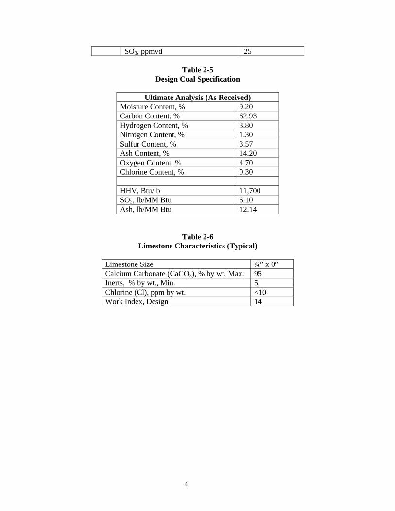
SO3, ppmvd 25
Table 2-5 Design Coal Specification
Ultimate Analysis (As Received)
Moisture Content, % 9.20 Carbon Content, % 62.93 Hydrogen Content, % 3.80 Nitrogen Content, % 1.30 Sulfur Content, % 3.57 Ash Content, % 14.20 Oxygen Content, % 4.70 Chlorine Content, % 0.30 HHV, Btu/lb 11,700 SO2, lb/MM Btu 6.10 Ash, lb/MM Btu 12.14
Table 2-6 Limestone Characteristics (Typical)
Limestone Size ¾” x 0” Calcium Carbonate (CaCO3), % by wt, Max. 95 Inerts, % by wt., Min. 5 Chlorine (Cl), ppm by wt. <10 Work Index, Design 14

5
Table 2-7 Water Analyses
Constituent Clarified River Water Plum Creek River Water
Calcium (Ca), mg/l 19.6 53.5 Chloride (Cl), mg/l 10.9 86 Magnesium (Mg), mg/l 6.24 13 Nitrate (NO3), mg/l 3.0 1.9 Phosphate (PO4), mg/l 0.4 0.1 Potassium (K), mg/l 2.4 3 Silica (SiO2), mg/l 4.6 12.3 Sodium (Na), mg/l 11.8 75.5 Sulfate (SO4), mg/l 38.0 144 pH 6.4 7.2 TDS, mg/l 140 406 TSS, mg/l 11.0 300 Turbidity, NTU 25.0 27 M-Alkalinity, mg/l CaCO3
43.0 64
Conductivity, umhos/cm 244 -- Aluminum (Al), mg/1 0.48 1.16 Barium (Ba), mg/l 0.04 -- Iron (Fe), mg/l 0.95 1.62 Manganese (Mn), mg/l 0.07 0.16 Zinc (Zn), mg/1 0.01 --
3.0 PERFORMANCE PARAMETERS
The following is a summary of key performance requirements that are valid over the entire range of operating conditions and loads of the boiler that will be demonstrated during the guarantee period.
Table 3-1 Summary of Key Performance Requirements
No. Parameter Performance Requirement
1. SO2 Removal Efficiency
98 percent (minimum) at design condition corresponding to 3.57 percent sulfur coal and 6.0 lb/MMBtu, with a chloride concentration in the absorber reaction tank recirculating slurry less than or equal to 20,000 ppmw.
2. Particulate Emission
0.03 lb/MMBtu (maximum) at design condition corresponding to an inlet loading of 0.1 lb/MMBtu
3. Sulfuric Acid Mist Emission
8 ppmv dry at design condition corresponding to an inlet concentration of 23 ppmv dry

6
4. Ionic Mercury
Removal Efficiency 80%
5. Liquid Carryover by Flue gas from FGD System
0.025 grains/acf at all operating conditions.
6 FGD System Reliability 99 % over 18 months
Other performance parameters are:
a. Gas pressure drop across FGD system b. Mist eliminator life c. Gas pressure drop across mist eliminators d. Accumulation of solids deposit on bottom of FGD outlet duct e. Oxidation stoichiometric ratio f. Gypsum solids oxidation ratio g. Limestone stoichiometric ratio h. Limestone consumption rate i. Limestone particle size in slurry j. Seal water requirements – clarified water k. Makeup water requirements – Plum Creek river water l. Water balance m. Instrument air usage n. Service air usage o. Total electrical power requirements p. Noise levels q. Gypsum production rate per unit r. Gypsum production rate per filter s. Chloride purge stream flow rate and quality t. Gypsum quality
4.0 PROJECT EXECUTION APPROACH & SCHEDULE
The Project was executed using multiple lump sum contracts with Shaw performing construction management services. The major contract packages include: • FGD System including absorber vessels, recycle pumps, ball mills with associated
limestone preparation equipment, limestone addition system, primary dewatering system, and vacuum belt filters with associated secondary dewatering system equipment
• Material Handling System, including limestone and gypsum handling and storage. • Chimney system with brick flue liners • Flue Gas Ductwork and Supports • Flue Gas Booster Fans • Wastewater Treatment System equipment supply

7
• Wastewater Treatment System BOP design and installation • Auxiliary Transformers • Makeup Water Pump-house and Treatment System • Railroad Installation • Various contracts associated with balance of plant work including site preparation,
foundations, structural steel and building erection, duct-bank, electrical installation, mechanical installation, field erected tanks, piping, DCS, relocations, and miscellaneous site-related systems
A summary of the type and the number of Contract Packages for the project is given in Table 4-1.
TABLE 4-1
SUMMARY OF CONTRACT PACKAGES
CONTRACT PACKAGE NUMBER OF PACKAGES CONSTRUCTION AND FURNISH AND ERECT 36 EQUIPMENT AND MATERIAL 24 SERVICES: Including Engineering and Consultants 6 TOTAL 66 Limited Start Activities for major equipment procurements were initiated in November 2005, with full engineering release in July 2006. Construction of the foundations for the chimney and absorbers began in November 2006, and flue gas admission to the first unit absorber is scheduled for April 2009, and to the second unit absorber is scheduled for November 2009. The construction of FGD systems for Units 1 and 2 is presently in progress. A summary-level Project Schedule with major milestone dates is shown in Figure 1.
5.0 SYSTEM CONFIGURATION AND DESIGN FEATURES
The FGD System operates in conjunction with the existing pulverized coal-fired, balanced draft boilers, including FD and ID fans, air heaters, and precipitators.
The FGD system consists of two (2) absorber trains, one per 850 MW Unit, and a limestone preparation system and a gypsum dewatering system which are common to the two units. A common Waste Water Treatment System (WWTS) processes the effluent from the FGD systems for the two units. A process flow diagram for the FGD system is shown in Figure 2.
5.1 Design Features of the FGD System
Some of the additional design features of the Keystone FGD system are:
a. Each absorber, with a diameter of 66 feet, is one of the largest single open spray/tray towers in the world. Each tower is dedicated to a unit and processes an inlet gas volumetric flow of approximately 3.25 million acfm. The design will reduce the SO2 in the flue gas from an inlet concentration of approximately

8
2,400 ppm wet to an outlet concentration of approximately 42 ppm wet for a removal efficiency of 98 percent.
b. The limestone preparation system consists of three (3) ball mills (two operating and one common spare), each with a capacity of 50 TPH.
c. The gypsum dewatering system consists of three (3) horizontal belt filters (two operating and one common spare) each with a capacity of 75 TPH.
d. The FGD system operates in an open loop where the chlorides and fines concentration are controlled by a purge stream to a Waste Water Treatment System.
e. The FGD system has no bypass.
f. AL6XN or equivalent 6-Moly material solid plates are used for the spray towers and recycle tanks.
g. Solid Hastalloy (C-276) is used in the inlet duct transition zone, at the inlet deflector and inlet side shields of the absorber, and for the chimney liner exit nozzles.
h. Hastalloy (C-276) clad carbon steel is used for the absorber outlet duct, and the chimney breechings.
i. All inlet duct work is of carbon steel except for 12 feet (from the periphery of the absorber vessel) of wet/dry zone duct at the inlet to the absorber. Absorber outlet transition and elbow are of solid AL6XN or equivalent 6-Moly stainless steel and the outlet duct to the chimney is 1/16” C-276 roll-bonded carbon steel.
j. New Booster Fans are added to the discharge duct from the existing ID Fans of each unit to handle the increased pressure drop of the FGD system.
k. Each absorber module is designed with a tray on the lower entry level and five operating spray levels. Each absorber vessel will include a recycle mix tank with oxidation air system at the bottom and two stages of horizontal mist eliminators at the top.
l. Limestone will be delivered to the plant by rail or truck. Unloading facilities include unloading hoppers, and belt conveyors feeding three, 12-hour capacity, ball mill feed silos. Active and inactive storage piles will be maintained at the site.
m. Primary dewatering will be accomplished by hydroclones to produce an underflow by-product containing approximately 50 percent solids. Each unit will have dedicated hydrocyclones with the overflow returned to the unit's absorber vessel. The hydrocyclone underflow will be processed in a common secondary dewatering system consisting of three vacuum belt filters.
n. The existing electrostatic precipitators will remain in service.

9
o. Two sources of makeup water are available to the plant. Clarified River Water will be used to wash the mist eliminators and for the vacuum pump seals as well as for humidification of the oxidation air. Plum Creek River Water will be used as makeup water to the limestone preparation system and as emergency quench water to the absorbers.
p. All slurry pipes external to the absorbers are of abrasion resistant FRP. Internal piping within the absorber is AL6XN or equivalent 6-Moly material.
q. All clear water lines and low solid slurry lines, such as filtrate lines, are FRP lines with abrasion resistant coating.
r. The mist eliminator water storage tank and makeup water tanks are carbon steel with epoxy lining. The mill product tanks and filtrate receiver tanks are rubber-lined carbon steel. The vacuum filter cake wash tank is 316 SS. The organic acid tank is FRP. All other FGD system tanks are flakeglass-lined carbon steel.
s. All pumps have mechanical seals with no seal water requirement.
t. All rotating equipment such as pumps and compressors are equipped with appropriate redundant spares.
5.2 Unique Features of the FGD System and WWTS
The Keystone FGD and WWT systems have several site-specific unique features. Some of the unique features include the following:
Acid Brick – Alloy wet Chimney: A new 562.5 foot high wet chimney that consists of three basic sections – lower breeching section, main mid-section consisting of two dedicated acid brick flues, and upper conical section to optimize dispersion effects to the atmosphere.
Spare Spray Bank & DBA System: SO2 removal efficiency of 98% with five spray banks, lower tray and no spare spray banks. Provisions are made to allow for the future application of a DBA addition system and operation with four spray banks (the fifth bank will be a future spare).
Waste Water Treatment System: A common WWTS with provisions for the future installation of a biological treatment system to enhance BOD, COD and trace element removal.
6.0 REDUNDANCY & SPARING PHILOSOPHY
The following Table describes the equipment list and sparing philosophy for major components of the FGD System.

10
Table 6-1 Equipment List
Component Name Area Location Total Installed Quantity
Limestone Preparation Area Equipment
Limestone Silo Limestone Slurry Prep Area
1 per train
Total of 3
Limestone Silo Bin Vent Filter
Limestone Slurry Prep Area
1 per train
Total of 3
Ball Mill Limestone Weigh Feeder
Limestone Slurry Prep Area
1 per train
Total of 3
Limestone Ball Mill Limestone Slurry Prep Area
1 per train
Total of 3
Ball Charger System Limestone Slurry Prep Area 1 Total
Reject Ball Collection System
Limestone Slurry Prep Area
1 per train
Total of 3
Mill Slurry Tank Limestone Slurry Prep Area
1 per train
Total of 3
Mill Slurry Tank Agitator Limestone Slurry Prep Area
1 per tank
Total of 3
Mill Slurry Pump Limestone Slurry Prep Area
1 Operating & 1 Spare per ball mill train
Total of 6
Mill Slurry Hydroclone System
Limestone Slurry Prep Area
1 cluster per train
Total of 3
Product Diverter Box Limestone Slurry Prep Area
1 per train
Total of 3
Limestone Slurry Feed Pump
Limestone Slurry Prep Area
2 per Limestone Slurry Storage Tank, 1 operating, and 1 spare
Total of 4.

11
Component Name Area Location Total Installed Quantity
Limestone Slurry Storage Tank
Limestone Slurry Prep Area Total of 2
Limestone Slurry Storage Tank Agitator
Limestone Slurry Prep Area
1 per tank
Total of 2
Limestone Slurry Supply & Recirculation Loop
Connects Limestone Slurry Prep Area to Absorber Area
1 per Limestone Slurry Storage Tank for a total of 2 loops
Limestone Prep Building Area Sump Pump
Limestone Slurry Prep area
1 Operating and 1 spare
Total of 2
Limestone Prep Building Area Sump Agitator
Limestone Slurry Prep area 2 Total
Absorber Area Equipment
Absorber Reaction Tank Absorber Area (lower portion of Absorber Module)
2 Total (one for each absorber)
Absorber Reaction Tank Agitators Absorber Area
Six (6) agitators required for uniform and off-bottom suspension of slurry, with no recycle pump in operation.
Absorber Absorber Area One absorber for each unit.
Total of 2
Absorber Spray Level Absorber Area
Five (5) spray levels to meet required SO2 removal at design conditions. No spare.
Absorber Recycle Pump Absorber Area One pump per level
Total of 5
Absorber Oxidation Air Compressor Absorber Area
2 operating (1 per absorber) + 1 common spare
Total of 3

12
Component Name Area Location Total Installed Quantity
Absorber Bleed Pump Absorber Area 1 Operating and 1 spare per Absorber
Total of 2
Make-up Water Pump Make-up Water Area 3 for two tanks (2 operating + 1 spare)
Total of 3
Diesel-Driven Emergency Quench Pumps Make-up Water Area
1 per tank
Total of 2
Mist Eliminator Wash Water Pump Make-up Water Area
1 for each unit and 1 common spare, all cross-tied
Total of 3
Absorber Area Sump Pumps Absorber Area
1 Operating
1 Spare per sump
Total of 4
Absorber Area Sump Agitator Absorber Area Total of 2
Dewatering Area Equipment
Primary Hydroclone Cluster Dewatering Area
1 for each unit and 1 common spare.
Total of 3
Secondary Hydroclone Cluster Dewatering Area
1 for each unit and 1 common spare.
Total of 3
Secondary Hydroclone Feed Tanks Dewatering Area
1 per unit
Total of 2
Secondary Hydroclone Feed Tank Agitators
1 for each tank
Total of 2
Secondary Hydroclone Feed Pumps
2 (1 operating and 1 spare) for each tank
Total of 4

13
Component Name Area Location Total Installed Quantity
Gypsum Dewatering Filter Dewatering Area
2 Operating (1 per unit)
1 Spare (Common to 2 units)
Total of 3
Gypsum Cake Wash Pump Dewatering Area 1 per train
Total of 3
Dewatering Filter Vacuum Pump Dewatering Area
1 per train
Total of 3
Dewatering Filter Filtrate Receiver Dewatering Area
1 per train
Total of 3
Dewatering Filter Vacuum Pump Separator Dewatering Area
1 per train
Total of 3
Dewatering Filter Filtrate Pump Dewatering Area
1 per train
Total of 3
Dewatering Area Sump Pump Dewatering Area
1 Operating, 1 Spare
Total of 2
Dewatering Area Sump Agitator Dewatering Area Total of 2
Chloride Purge Tank Dewatering Area 1 (common to 2 units)
Absorber Drain Tank FGD Area 1 (common to 2 units)
Absorber Drain Tank Pumps FGD Area Total of 2
Absorber Drain Tank Agitators FGD Area 4 minimum
Chloride Purge Pump Dewatering Area 1 Operating, 1 Spare
Total of 2
7.0 MATERIALS OF CONSTRUCTION
The materials of construction selected for the FGD System are of proven, rugged, reliable design, entirely suitable for continuous, dependable service as expected of flue gas scrubbing

14
systems for electric utilities. All materials have the requirement of a satisfactory history of performance for at least five years of operating service in similar utility FGD applications.
The FGD System process design and material selection are based on a chloride equilibrium FGD solution concentration of 20,000 ppmw (by weight) on the average and a maximum of 25,000 ppmw:
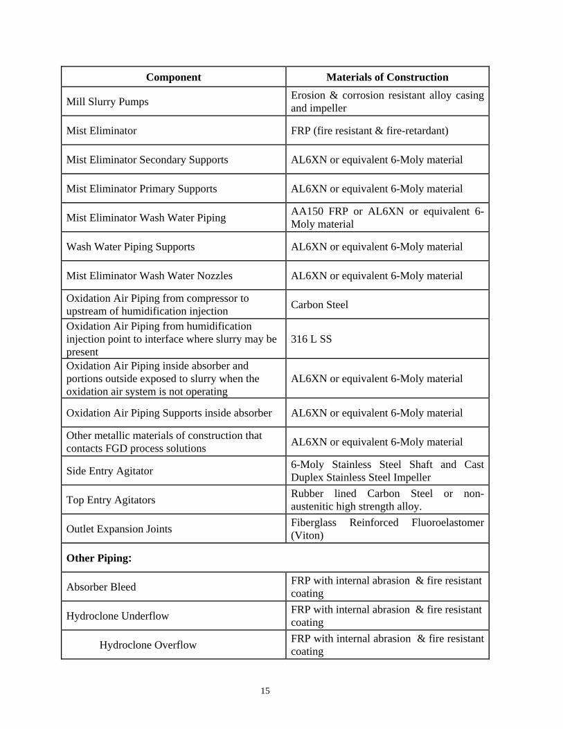
The following Table summarizes the materials of construction for the major FGD System equipment components.
Table 7-1 FGD System Material of Construction
Component Materials of Construction
Absorber Inlet Duct (Minimum 15 feet wet/dry zone) Solid C-276, 0.25” thick (Minimum)
Absorber Inlet Deflector and Side Shields Solid C-276, 0.25” thick (Minimum)
Absorber Outlet Transition and Elbow AL6XN or equivalent 6-Moly material
Absorber Outlet Duct 1/16” C-276 Roll bonded over carbon steel
Absorber Reaction Tank AL6XN or equivalent 6-Moly material
Absorber Vessel Walls AL6XN or equivalent 6-Moly material
Tray AL6XN or equivalent 6-Moly material Internals Support AL6XN or equivalent 6-Moly material Turning Vane in Outlet Duct Solid C-276 Oxidation Sparger AL6XN or equivalent 6-Moly material Absorber & Reaction Tank Access Doors AL6XN or equivalent 6-Moly material
External Recycle Piping A150 FRP internal abrasion resistant
Internal Recycle Piping/Headers/Absorber Piping Penetrations AL6XN or equivalent 6-Moly material
Recycle Spray Nozzles Silicon Carbide connected to spray header with flange with Victaulic couplings.
Recycle & General Service Slurry Pumps Rubber Lined Casing with Alloy Impeller and throat bushing and AL6XN suction valves
15
Component Materials of Construction
Mill Slurry Pumps Erosion & corrosion resistant alloy casing and impeller
Mist Eliminator FRP (fire resistant & fire-retardant)
Mist Eliminator Secondary Supports AL6XN or equivalent 6-Moly material
Mist Eliminator Primary Supports AL6XN or equivalent 6-Moly material
Mist Eliminator Wash Water Piping AA150 FRP or AL6XN or equivalent 6-Moly material
Wash Water Piping Supports AL6XN or equivalent 6-Moly material
Mist Eliminator Wash Water Nozzles AL6XN or equivalent 6-Moly material
Oxidation Air Piping from compressor to upstream of humidification injection Carbon Steel
Oxidation Air Piping from humidification injection point to interface where slurry may be present
316 L SS
Oxidation Air Piping inside absorber and portions outside exposed to slurry when the oxidation air system is not operating
AL6XN or equivalent 6-Moly material
Oxidation Air Piping Supports inside absorber AL6XN or equivalent 6-Moly material
Other metallic materials of construction that contacts FGD process solutions AL6XN or equivalent 6-Moly material
Side Entry Agitator 6-Moly Stainless Steel Shaft and Cast Duplex Stainless Steel Impeller
Top Entry Agitators Rubber lined Carbon Steel or non-austenitic high strength alloy.
Outlet Expansion Joints Fiberglass Reinforced Fluoroelastomer (Viton)
Other Piping:
Absorber Bleed FRP with internal abrasion & fire resistant coating
Hydroclone Underflow FRP with internal abrasion & fire resistant coating
Hydroclone Overflow FRP with internal abrasion & fire resistant coating

16
Component Materials of Construction
Filtrate FRP with internal abrasion & fire resistant coating
Limestone Slurry FRP with internal abrasion & fire resistant coating
Hydroclone Components
Primary Hydrocyclone Body of Carbon Steel with minimum 1/4” rubber lining, Ceramic apex and vortex finders
Secondary Hydrocyclone Body of Carbon Steel with minimum 1/4” rubber lining, Polyurethane apex and vortex finders
Underflow Launder Rubber-Lined Carbon Steel
Overflow Launder Rubber-Lined Carbon Steel
Piping FRP with internal abrasion resistant coating
Distribution Inlet Piping Neoprene-Lined Carbon Steel
In addition, linings in slurry service in tanks and sumps use abrasive resistant brick or other abrasive resistant linings for tank floors and three feet up the side walls of the tanks.
8.0 SYSTEM CONTROL AND OPERATING PHILOSOPHY
Performance of the FGD System is maintained through several control loops that function in the automatic mode, as well as by other instruments that continuously monitor critical parameters of the system.
The critical automatic control loops include the following:
a. SO2 removal is controlled by a feed forward control system that is tied into the inlet flue gas volume and SO2 concentration and the desired removal efficiency
b. Limestone addition to the absorber is controlled by the pH of the recycle slurry. Grab samples and laboratory analysis will confirm the pH measured by the inline instruments.
c. Mist Eliminator washing is controlled through a wash cycle primarily based on unit load, and interfaced with the absorber vessel liquid level

17
d. Percent solids or density of the absorber recycle slurry is maintained by controlling the primary dewatering hydroclone underflow to feed either the filter or return to the absorber. Grab samples and laboratory analysis will confirm the density measured by the inline instruments.
e. Chloride concentration of the absorber recycle slurry is maintained by controlling the chloride purge to the WWTS. This in turn is maintained by controlling the overflow from the primary dewatering hydroclones to the secondary hydroclone feed tank, enroute to the Chloride Purge Tank. Grab samples and laboratory analysis will confirm the chloride concentration.
The following parameters will be monitored on a continuous basis and will be available for access and display in the Control Room.
• Unit Load - MWe • Inlet Gas Temperatures - oF • Outlet Gas Temperature - oF • Outlet Gas Conditions at the Chimney • Inlet SO2 Concentration - ppm • Inlet CO2 Concentration - % by Volume • NOx Emission - lb./MMBtu (Hourly, Daily and Yearly Averages) • SO2 Emission - lb./MMBTU (Hourly, Daily and Yearly Averages) • Chimney Gas Velocity - fps • Chimney Gas Flow - kcfm • Chimney Gas Temperature - oF • Pressure Drop - in. WC • Absorber Vessel Liquid Level • Recycle Slurry Solids Content - % by Wt. • Recycle Slurry pH • Oxidation Air Flow Rate, Temp. and Pressure - SCFM, oF, psig • Mist Eliminator Wash Flow Rate and Pressure GPM and psig • Bleed Slurry Flow Rate to Hydrocyclones - GPM • Bleed Slurry Pressure at Hydrocyclone Inlet - psig
9.0 CHIMNEY
A new chimney with a concrete shell and two flues, each dedicated to one unit, will be installed to discharge wet flue gas from the absorber to the atmosphere. The new chimney is a non-reheat, [low velocity], or "wet" stack. A sketch of the chimney and the flue is shown in Figure 3. Additional details of the chimney are:
a. Overall height - 562.5 ft. b. Outer Shell - Reinforced concrete, common to both units c. No. of Flues - Two - one for each unit d. Liner:
1) Material - Acid Resistant Brick

18
2) Diameter - 36’ 6” 3) Length - 347’ 2” (from an elevation of 191’10”to 539’0”) 4) Velocity - 45 fps
e. Inlet Thimble: 1) Material - C276 Roll bonded (1/16” in.) carbon steel 2) Diameter - 33’ 0” 3) Length - 66’ 10” (from an elevation of 125’ 0” to 191’ 10”) 4) Velocity - 55 fps
f. Inlet Breeching: 1) Material - C276 Roll bonded (1/16” in.) carbon steel 2) Dimensions - Height: 34’ 0”; Width: 22’ 8” ft. 3) Velocity - 60 fps
g. Exit Nozzle (Conical): 1) Material - Solid C276 2) Diameters (Bottom/Top) - 36’6” & 33’ 0” 3) Length - 23’ 6” 4) Velocity
(Inlet/Exit) - 45 fps/55 fps 5) Extn. Above
Concrete Shell - 19’ 6”
Other pertinent details of the chimney are:
a. Liquid collectors made of solid C276 are installed to collect and drain any condensate and liquid carry over from the absorber. The liquid collected is drained by gravity to respective absorber.
b. An annular pressurization system is provided to minimize potential migration of moisture through the brick liner.
c. A dilution extraction type CEMs is installed. The system continuously monitors SO2, NOx and gas velocity. Appropriate sampling ports, access platforms and elevators are provided for operation and maintenance of the CEMs.
d. The outer surface of the concrete shell will have acid resistant coating for a height of 120 ft. from the chimney top to protect the shell from plume down-wash. This height was determined by a separate plume model study.
10.0 WASTE WATER TREATMENT SYSTEM
The WWT design incorporates the influent characteristics and the allowed characteristics for final discharge. Modeling of the WWT effluent characteristics was modeled using the state’s water quality model. The modeling assisted in selecting the proper treatment system.
The WWT influent values are dependent upon the trace analysis of coal, makeup water, and limestone used in the absorber. The wastewater treatment system is also dependent upon the absorber’s purge rate and temperature.

19
Characteristics of the absorber purge stream and results from the model were incorporated into the selection process to select a physical-chemical treatment process to control pH, total suspended solids removal, and total heavy metals removal. Referring to the wastewater treatment flow diagram in Figure 4, the wastewater treatment system incorporates a pH adjustment step, a chemical reaction and sedimentation process, dewatering step, and a filtration step.
The chloride purge stream is pumped from the absorber building to the equalization tank located in the wastewater treatment area. To minimize upsets in the wastewater treatment system, the equalization tank is used to equalize any possible chemical or hydraulic fluctuations resulting from absorber operations. The equalization tank also collects backwash reject from the continuous backwash filters, filtrate from the dewatering system, building trench drains, and tank overflows. The equalized wastewater is then pumped from the equalization tank to the desaturation tank. In order to precipitate out soluble metals as insoluble hydroxides and oxy-hydroxides, the pH is adjusted to a pH between 8.5 and 9.2. Hydrated lime is added to the desaturation tank to raise the pH.
Due to the highly saturated gypsum in the wastewater, scaling is inevitable. To minimize the potential scaling in the system, gypsum desupersaturation is carried out in the desaturation tank. Gypsum desupersaturation occurs by introducing seed crystals for gypsum nucleation into the desaturation tank by recycling the underflow from the downstream clarifiers.
The wastewater flows by gravity to a heavy metals tank. A sulfide reagent is added to the tank to form heavy metal sulfide complexes. Heavy metal sulfide complexes have low solubility products, which aids in maximizing heavy metal removal in the clarifiers.
The wastewater then flows into a flow splitter tank which partitions the flow into two clarifiers. As the flow is partitioned in the flow splitter tank, a coagulant is added to create a dense flocculent to aid in the clarification process.
The chemically treated wastewater is then gravity fed from the flow splitter tank to the two clarifiers. Polymer is added to the clarifier to enhance the settling characteristics of the wastewater. The solids collected by the clarifier are either pumped to a sludge holding tank or recycled for the desupersaturation step in the desaturation tank. The clarified overflow, from both clarifiers, is directed by gravity to a collection tank. The clarifier underflow is pumped to a sludge collection tank. The sludge is then pumped into a plate and frame press to dewater the sludge. The dewatered sludge is collected in a truck and trucked to a landfill. The filtrate is sent back to the equalization tank.
The clarified liquor, which is collected in a collection tank, is then pumped through a heat exchanger for cooling. If cooling is not required, the clarified liquor will bypass the heat exchanger. The pH is lowered by injecting hydrochloric acid prior to the heat exchanger. Lowering the pH is required for discharge and the lower pH helps to minimize scaling. The plate and frame heat exchanger has been designed to cool the clarified liquor from a maximum temperature of 130°F down to a temperature of 95°F.
The liquor is then filtered by passing through a continuous backwash filter system. The filtered liquor is pumped through final polishing filters to meet the stringent requirements of Total Suspended Solids in the WWT effluent. The treated wastewater is then collected in the head tank for final discharge.

20
11.0 PERFORMANCE REQUIREMENTS AND TESTING APPROACH
The following Table identifies the test methods to be used to demonstrate performance by the FGD System and the number of Acceptance Tests used to verify compliance. The Table also identifies which performance parameters are subject to the use of parametric graph corrections to demonstrate compliance at conditions other than those used during the tests.
Table 11-1
Performance Tests & Test Methods
No. Parameter Test Method Acceptance Test 1
Acceptance Test 2
Parametric Graphs
1 SO2 Removal Efficiency EPA Method 19
Yes Yes
No
2 Particulate Emission EPA Method 5B
Yes Yes No
3 Sulfuric Acid Mist Emission
Controlled Condensate Method
Yes No No
4 Mercury Removal Efficiency
Ontario Hydro Method
Yes No No
5 Liquid Carryover by Flue Gas from FGD System
KOCH’S PDPA Method
Yes Yes No
6 Gas Pressure Drop Across FGD System
EPA Method 1, Kiel Probe
Yes Yes Yes
7 Mist Eliminator Life 5 Years No No 8 Gas Pressure Drop
Across Mist Eliminators In-line DP Measurements
Warranty Period
No No
9 Accumulation of Solids Deposit on Bottom of FGD Outlet Duct
Field Weight Measurement
Yes No No
10 Oxidation Stoichiometric Ratio
In-line Measurements of Flow
Yes No No
11 Gypsum Solids Oxidation Ratio
EPRI Analytical Method, CS-3612
Yes Yes No
12 Limestone Stoichiometric Ratio
EPRI Analytical
Yes Yes No

21
No. Parameter Test Method Acceptance Test 1
Acceptance Test 2
Parametric Graphs
(SR) Method, CS-3612
13 Limestone Consumption Rate
Use of Equation Related to SR
Yes Yes Yes
14 Limestone Particle Size in Slurry
Sieve Measurements
Yes No No
15 Seal Water Requirements– Clarified Water
In-line Flow Measurements
Yes No No
16 Makeup water Requirements- Plum Creek River Water
In-line Flow Measurements
Yes No Yes
17 Water Balance In-line Flow Measurements
Yes No No
18 Instrument Air Usage In-line Flow Measurements
Yes No No
19 Service Air Usage In-line Flow Measurements
Yes No No
20 Total Electrical Power Requirements
Watt Meters Yes No Yes
21 Noise Levels Type 2 General Purpose Sound Level Meter
Yes No No
22 Gypsum Production Rate per Unit
In-line Weight Measurements
Yes No Yes
23 Gypsum Production Rate per Filter
In-line Weight Measurements
Yes No Yes
24 Chloride Purge Rate and Quality
In-line Flow Measurement; Gravimetric % Solids Analysis
Yes No Yes
25 FGD System Reliability Over 18 Month Period
Parameters: • SO2 Removal Efficiency • SO3 Emission • PM Emission • Mercury Removal Efficiency • Power Consumption • Limestone Consumption • Water Consumption • Belt Filter Capacity
26 Gypsum Quality EPRI Analytical
Yes No No

22
No. Parameter Test Method Acceptance Test 1
Acceptance Test 2
Parametric Graphs
Method, CS-3612
12.0 SUMMARY
The Keystone FGD system is designed to remove 98% of the inlet SO2 resulting from burning an eastern bituminous coal that contains 3.57 % sulfur. The system uses limestone slurry prepared by a wet ball mill to remove SO2 and in-situ forced oxidation followed by dewatering with horizontal belt filters to produce commercial grade gypsum. A waste water treatment system processes the effluent from the FGD system to remove trace elements and solids before discharging. Unique features of the system include a new hybrid acid brick – alloy-lined wet stack, removal of SO2 without the use of a spare spray stage with provisions for a future organic acid system in lieu of a spare spray stage, provisions for the future installation of a biological treatment system for enhanced BOD and COD removal. Additional system features include a single spray/tray tower per unit, common limestone preparation and gypsum dewatering systems for the two units. In addition to SO2 removal, performance requirements of the FGD system include particulate emissions, mercury removal, sulfuric acid mist removal, limestone and gypsum production, consumption of chemicals, utilities and water and quantity and quality of waste water effluent from the FGD system.

23

24

25

26