Design Safety Handbook - Department of Chemistry ... and... · Design&Safety Handbook ... The...
62
Millenium Edition Design & Safety Handbook FOR SPECIALTY GAS DELIVERY SYSTEMS Design & Safety Handbook FOR SPECIALTY GAS DELIVERY SYSTEMS Design & Safety Handbook
Transcript of Design Safety Handbook - Department of Chemistry ... and... · Design&Safety Handbook ... The...

Millenium
Edition
Design&SafetyHandbook
FOR SPECIALTY GAS DELIVERY SYSTEMS
Design&SafetyHandbook
FOR SPECIALTY GAS DELIVERY SYSTEMS
Design&SafetyHandbook


Design and Safety Handbook
Industrial processes must move at ever faster speeds in order to remain competitive in today’s
global economy. It is increasingly more important therefore to improve quality and reduce
the cost of the end product. At the same time, many industries are faced with meeting tougher
regulations governing process emissions. To prosper and grow in such an environment, reliable
testing methods are essential, both to ensure regulation compliance and to result in a quality
end product that is cost-effective to produce. Today’s analytical instrumentation is certainly
up to this challenge—yet these instruments can only be as reliable as the specialty gases used
to calibrate them.
Quality and performance are essential. This handbook will aid in the design and safe operation
of custom specialty gas delivery systems, as well as provide helpful background information
about typical delivery system components. Our goal is to help you acquire (or design) an efficient,
safe and reliable system that will provide the correct gas to the point where it is needed at the
specified purity level, pressure and flow rate.
As one of the world’s largest suppliers of specialty gas products and technology, Scott has
a history of working with agencies such as the U.S. Environmental Protection Agency (EPA),
the National Institute for Standards and Technology (NIST) and the Netherlands Measurement
Institute (NMi), helping to develop various protocols and certified reference materials.
Our products include high-purity gases and gas mixtures for industrial, scientific, laboratory,
electronics, medical, environmental, chemical and petrochemical applications, as well as
high-performance gas handling equipment. Scott’s Equipment Technology Group provides
expert design and construction services of custom gas delivery systems for any application.
This handbook is a compendium of the knowledge and experience gathered over many years
by our field representatives and our customers. We gratefully acknowledge their contributions.
Scott Specialty Gases

PAGECompressed Gases: Safety Considerations . . . . . . . . . . . . . . . . . . . . . . . . . . . . . . . . . . . . . . . . . . . . . . 1
Safe Handling and Use of Gas Cylinders. . . . . . . . . . . . . . . . . . . . . . . . . . . . . . . . . . . . . . . . . . . . . . . . 4
Gas Cabinets. . . . . . . . . . . . . . . . . . . . . . . . . . . . . . . . . . . . . . . . . . . . . . . . . . . . . . . . . . . . . . . . . . . . . . . 6
Pressure Regulators: Definitions and Descriptions . . . . . . . . . . . . . . . . . . . . . . . . . . . . . . . . . . . . . . . 7
Pressure Regulator Operation . . . . . . . . . . . . . . . . . . . . . . . . . . . . . . . . . . . . . . . . . . . . . . . . . . . . . . . 11
Pressure Regulator Maintenance . . . . . . . . . . . . . . . . . . . . . . . . . . . . . . . . . . . . . . . . . . . . . . . . . . . . . 13
Pressure Regulator Purging. . . . . . . . . . . . . . . . . . . . . . . . . . . . . . . . . . . . . . . . . . . . . . . . . . . . . . . . . . 14
System Design and Safety Considerations . . . . . . . . . . . . . . . . . . . . . . . . . . . . . . . . . . . . . . . . . . . . . 16
Pressure-Relief Valves . . . . . . . . . . . . . . . . . . . . . . . . . . . . . . . . . . . . . . . . . . . . . . . . . . . . . . . . . . . . . . 20
Sizing Gas Distribution Lines . . . . . . . . . . . . . . . . . . . . . . . . . . . . . . . . . . . . . . . . . . . . . . . . . . . . . . . . 20
Gas Delivery Systems. . . . . . . . . . . . . . . . . . . . . . . . . . . . . . . . . . . . . . . . . . . . . . . . . . . . . . . . . . . . . . . 23
Single-Station Systems . . . . . . . . . . . . . . . . . . . . . . . . . . . . . . . . . . . . . . . . . . . . . . . . . . . . . . . . . . . . . 24
Multiple-Cylinder Systems . . . . . . . . . . . . . . . . . . . . . . . . . . . . . . . . . . . . . . . . . . . . . . . . . . . . . . . . . . 24
Uninterrupted Gas Supply . . . . . . . . . . . . . . . . . . . . . . . . . . . . . . . . . . . . . . . . . . . . . . . . . . . . . . . . . . 25
Semiconductor Gas Delivery Systems . . . . . . . . . . . . . . . . . . . . . . . . . . . . . . . . . . . . . . . . . . . . . . . . . 28
Gas Service at the Instrument. . . . . . . . . . . . . . . . . . . . . . . . . . . . . . . . . . . . . . . . . . . . . . . . . . . . . . . . 30
Manifold Specification Worksheet . . . . . . . . . . . . . . . . . . . . . . . . . . . . . . . . . . . . . . . . . . . . . . . . . . . 32
Recommended Application Drawings . . . . . . . . . . . . . . . . . . . . . . . . . . . . . . . . . . . . . . . . . . . . . . . . 33
Product Information. . . . . . . . . . . . . . . . . . . . . . . . . . . . . . . . . . . . . . . . . . . . . . . . . . . . . . . . . . . . . . . 38
Recommended Pure Gas for Analytical Instrumentation. . . . . . . . . . . . . . . . . . . . . . . . . . . . . . . . . 41
Definitions and Terminology. . . . . . . . . . . . . . . . . . . . . . . . . . . . . . . . . . . . . . . . . . . . . . . . . . . . . . . . 51
Table Index:Table 1. Physical Properties of Gases. . . . . . . . . . . . . . . . . . . . . . . . . . . . . . . . . . . . . . . . . . . . . . . . 43
Table 2. Recommended Scott Gas Grades for Detectors. . . . . . . . . . . . . . . . . . . . . . . . . . . . . . . . 44
Table 3. Maximum Impurities in Various Scott Grade Gases . . . . . . . . . . . . . . . . . . . . . . . . . . . 46
Table 4. Recommended Scott Pure Gas Grades for Other Gas Analysis Instrumentation . . . . 47
Table 5. Listing of Specialty Gases by Category . . . . . . . . . . . . . . . . . . . . . . . . . . . . . . . . . . . . . . . 48
Table 6. Material Compatibility Guide . . . . . . . . . . . . . . . . . . . . . . . . . . . . . . . . . . . . . . . . . . . . . . 50
Table 7. Maximum Service Pressure Ratings . . . . . . . . . . . . . . . . . . . . . . . . . . . . . . . . . . . . . . . . . 20
Table 8. Capacity of Distribution Lines in SCFH (NL/min) @ 60°F (16°C) . . . . . . . . . . . . . . . . 21
Table 8A. Specific Gravity of Gases . . . . . . . . . . . . . . . . . . . . . . . . . . . . . . . . . . . . . . . . . . . . . . . . . . 22
Table 8B. Capacity Correction for Gases Other than Air . . . . . . . . . . . . . . . . . . . . . . . . . . . . . . . . 22
Table 9. Typical Cylinder Specifications . . . . . . . . . . . . . . . . . . . . . . . . . . . . . . . . . . . . . . . . . . . . . 54
TABLE OF CONTENTS

Design and Safety Handbook
1
All cylinders containing Scott gases are labeled, packaged and shipped according to national andinternational requirements, as well as industry standards. Transportation label diamonds, regardlessof color, indicate hazardous materials. Personnel handling any compressed gas should be familiarwith the potential hazards before using the gas. In addition to the chemical hazards of compressedgases, hazards accompanying high pressure or low temperature may also be present due to thephysical state of the gas (i.e. liquefied or nonliquefied). It is the responsibility of anyone workingwith gas to know first aid as well as particular gas properties.
It is also recommended that personnel who handle compressed gases engage in pre-job discussionwith their supervisor or another knowledgeable coworker before beginning any task. Safety andefficiency are knowledge! Outline the job step by step, as well as any actions necessary to completethe job. Address potential emergencies and the safe and proper measures necessary to avoid theseemergencies. Identify several scenarios that could result in gas leaks or other emergencies to be totally prepared to respond adequately. If there is doubt regarding proper safety procedures, consult your Scott Representative. Further information concerning the safe handling, storage anduse of compressed gases, in addition to the information presented in this handbook, is available from Scott Specialty Gases.
COMPRESSED GAS DEFINITIONS — either nonliquefied, liquefied or gas solution
Compressed Gas – The term “compressed gas” shall designate any material or mixture having inthe container an absolute pressure exceeding 40.6 psi (280 kPa) at 68°F (20°C) or any flammablematerial that is a gas at 68°F (20°C) and 14.7 psia (101.3 kPa). Most compressed gases will notexceed 2,000 to 2,640 psig (138 to 182 bar) though some will go up to 6,000 (414 bar).
Nonliquefied Compressed Gas – A gas other than gas in solution, that, under the charged pressure, is entirely gaseous at a temperature of 68°F (20°C).
Liquefied Compressed Gas – A gas that, under the charged pressure, is partially liquid at a temperature of 68°F (20°C).
Compressed Gas In Solution – A nonliquefied compressed gas that is dissolved in a solvent.
COMPRESSED GAS CATEGORIES
Corrosive Gases – Gases that corrode material or tissue with which they come in contact, or do so in the presence of water, are classified as corrosive. They are high-pressure, reactive and couldbe toxic, flammable and/or oxidizers. Most are hazardous in low concentrations over long periodsof time. It is essential that equipment used for handling corrosive gases be constructed of propermaterials. Use check valves and traps in a system where there is a possibility that water or otherinorganic materials can be sucked back into the cylinder. Due to the viability of irritation anddamage to the lungs, mucus membranes and eye tissues from contact, the threshold limit values of the gas should be rigidly observed. Proper protective clothing and equipment must be used tominimize exposure to corrosive materials. A full body shower and eye wash station should be inthe area. Personnel should be familiar with the work area, and aisleways should always be clear ofdebris and obstruction in the event that the gas makes contact with the eyes and vision is disrupted.
COMPRESSED GASES: SAFETY CONSIDERATIONS
Cylinder with Transport Labeling
Corrosive TransportationDiamond Label

Cryogenic Gases – Gases with a boiling point of -130°F (-90°C ) at atmospheric temperature are considered cryogenic gases. They are extremely cold and can produce intense burns similar to heat burns and tissue necrosis may even be more severe. They can be nonflammable, flammable or oxidizing. Cryogenic liquids can build up intense pressures. At cryogenic temperatures, systemcomponents can become brittle and crack. Never dead-end the line filled with liquid as a slightincrease in temperature can cause tremendous and dangerous buildup of hydrostatic pressure andcause the line to burst. The system should also be designed with a safety relief valve and, dependingupon the gas, a vent line. To protect from injury, always wear gauntlet gloves to cover hands andarms, and a cryogenic apron to protect the front of the body. Wear pants over the shoes to protectfrom liquids getting inside your shoes where it can become trapped. Wear safety glasses and a faceshield as cryogenic liquids tend to bounce up when they are spilled.
Flammable Gases – Gases that, when mixed with air at atmospheric temperature and pressure,form a flammable mixture at 13% or less by volume, or have a flammable range in air of greaterthan 12% by volume regardless of the lower flammable limit, are classified as flammable. They can be high-pressure, displace oxygen from the air, and can be toxic and reactive. A change intemperature, pressure or oxidant concentration may vary the flammable range considerably. All possible sources of ignition must be eliminated through proper design of facilities and therestriction of smoking and open flames. Use a vent line made of stainless steel, purge with an inert gas and use a flash arrester. It is important to have (and know how to use) a fire extinguisherin the area where flammable gases are used (and stored), as well as a hand-held flammable gasdetector to determine if flammable gases are building up and as a leak detector on the lines of theequipment being used. Always remember that the source of flammable gas must be stopped beforeattempting to put out a fire involving flammable gases.
Inert Gases – Gases that do not react with other materials at ordinary temperature and pressureare classified as inert. They are colorless and odorless, as well as nonflammable and nontoxic. The primary hazards of these gases are pressure and asphyxiation. These gases are often stored atpressures exceeding 2,000 psi (138 bar). Also, they can displace the amount of oxygen necessary tosupport life when released in a confined place. Use of adequate ventilation and monitoring of theoxygen content in confined places will minimize the danger of asphyxiation. Always wear safetyglasses and safety gloves when working with the lines to avoid absorption of the gas through the skin.
Oxidant Gases – Gases that do not burn but will support combustion are classified as oxidants.They can be high-pressure, displace breathing oxygen from air (except O2 itself), and are toxic and reactive. It is essential that all possible sources of ignition be eliminated when handling oxygen and other oxidants as they react rapidly and violently. Do not store combustible materialswith oxidants. Do not allow oil, grease or other readily combustible materials to come in contactwith cylinder or equipment used for oxidant services. Use only equipment that is intended for this type of service. Use only a regulator that has been clearly prepared for use with this type of service— this regulator should be labeled “Cleaned for O2 Services.”
2
Flammable TransportationDiamond Label
Nonflammable TransportationDiamond Label
Oxidizing TransportationDiamond Label

Toxic or Poison Gases – Gases that may chemically produce lethal or other health effects onhumans are classified as toxic or poison. They can be high pressure and reactive, and can benonflammable, flammable, or oxidizing in addition to their toxicity. The degree of toxicity and the effects will vary depending on the gas; however, death will occur when breathed insufficient quantities. The permissible exposure levels must be strictly adhered to (please refer to the U.S. OSHA PEL’s or the MAC Limits listed in Scott’s Specialty Gases Reference Guide).Read your MSDS thoroughly before use and consult with your Scott Representative or a moreknowledgeable coworker who has handled the gas before. Never work alone with toxic gases — a safety person is essential! Consider the entire assembly or system that will contain the gas andthoroughly test it for leaks with an inert gas before use. Purge all lines with an inert gas beforeopening the cylinder valve or breaking connections (contact your Scott Representative for proper purge procedures).
Use toxic gases in a well-ventilated area. For safety purposes and to minimize exposure, it isimportant to have gas detectors, sensor alarm systems to monitor oxygen concentration, gas masks,self-contained breathing apparatus and protective clothing on hand. Full body showers, eye washes,fire alarms and firefighting equipment should be in the area of use and readily accessible. It ispreferable that the breathing apparatus be stored in a safe area immediately adjacent to thework area, so that in the event of an emergency, a person can go directly into the area and close the door and safely put on the apparatus. Consult your local building code for storage and userequirements for toxic gases.
Finally, keep a minimum inventory of toxic or poison gases. When a project is completed, returnleftover cylinders to Scott. They should never be stored for possible future use. This might result in accidental removal of cylinder labeling, making it an unnecessary hazard and greatly increasingthe cost of proper disposal.
Design and Safety Handbook
3
Poison TransportationDiamond Label

STORAGE
General – Appropriate firefighting, personnel safety and first aid equipment should be available in case of emergencies. Ensure adequate personnel are trained in the use of this equipment.
Follow all federal, state and local regulations concerning the storage of compressed gas cylinders.Refer to the Compressed Gas Association (CGA) pamphlet P-1 in the U.S. for further informationor consult EIGA (European Industrial Gas Association), CPR-15 or CIMAH in Europe.
Storage Area – Store gas cylinders in a ventilated and well-lit area away from combustible materials.Separate gases by type and store in assigned locations that can be readily identified. Store cylinderscontaining flammable gases separate from oxygen cylinders and other oxidants by a fire-resistantbarrier (having a fire-resistance rating of at least a half-hour) or locate them at least 20 feet (6.1 meters) apart from each other. Labels, decals, or other cylinder content identification shouldnot be altered or removed from the gas cylinder. Cylinders should also be stored where they can beprotected from tampering by unauthorized personnel.
Storage Area Conditions – Storage areas should be located away from sources of excess heat, openflame or ignition, and not located in closed or subsurface areas. The area should be dry, cool andwell-ventilated. A hood is not a safe storage area except for when the cylinder is actually in use.Outdoor storage should be above grade, dry and protected from the extremes of weather.
Securing Cylinders in Storage – The risk of a cylinder falling over demands that a cylinder alwaysbe held in place with a chain or another type of fastener such as a bench or wall clamp. While instorage, cylinder valve protection caps MUST be firmly in place.
Cylinder Temperature Exposure – Cylinder temperature should not be permitted to exceed 125°F (52°C). Steel cylinders are more durable than aluminum cylinders. They are designed for high-pressure and for more corrosive products, and they should not be stored near steampipelines or exposed to direct sunlight. Aluminum cylinders are used for increased stability of mixtures containing certain components. They can be damaged from exposure to temperatures in excess of 350°F (177°C). These extremes weaken the metal walls, and the cylinders will lose their strength. Do not apply any heating device that will heat any part of the cylinder above 125°F(52°C). Overheating can cause the cylinder to rupture.
Empty Cylinders – Arrange the cylinder storage area so that old stock is used first. Empty cylindersshould be stored separately and clearly identified. Return empty cylinders promptly. Some pressureshould be left in a depleted cylinder to prevent air backflow which would allow moisture and contaminants to enter the cylinder.
HANDLING
General – Safety glasses, gloves and shoes should be worn at all times when handling cylinders.Appropriate firefighting, personnel safety and first aid equipment should be available in case of emergencies.
Transporting Cylinders – Always move cylinders by hand trucks or carts that are designed for this purpose. During transportation, cylinders should be properly secured to prevent them fromfalling, dropping or striking each other. Never use a cylinder cart without a chain. Do not move acylinder with a regulator connected to it. Never transport a gas cylinder without its valve protectioncap firmly in place. Keep both hands on the cylinder cart during transport. A cylinder cart or handtruck is not a suitable place for storage of a cylinder.
4
SAFE HANDLING AND USE OF GAS CYLINDERS
Scott Cylinder Rack Model 55-84CS
stores cylinders safely.
Scott Cylinder Cart Model 55-81
transports cylinders safely.

USAGE
General – Appropriate firefighting, personnel safety and first aid equipment should be available in case of emergencies.
Labeling – If a cylinder’s content is not clearly identified by proper labels, it should not beaccepted for use.
Securing Cylinders before Use – When a cylinder is in use, it must be secured with a fastener.Floor or wall brackets are ideal when a cylinder will not be moved. Portable bench brackets arerecommended when a cylinder must be moved around. Smaller stands are available for cylindersas well as for lecture bottles. Your Scott Representative can assist you in determining which type of cylinder fastener best meets your needs.
Initiating Service of Cylinder – Secure the cylinder before removing the valve protection cap.Remove the protective cap and inspect the cylinder valve for damaged threads, dirt, oil or grease.Remove any dust or dirt with a clean cloth. If oil or grease is present on the valve of a cylinder thatcontains oxygen or another oxidant, DO NOT attempt to use it. Such combustible substances incontact with an oxidant are explosive. Notify the nearest Scott facility of this condition and identifythe cylinder to prevent usage.
CGA, DIN, BS and NEN Connections and Fittings – Be sure all fittings and connection threadsmeet properly. Never force the connection. NEVER cross-thread! NEVER use adapters betweennonmating equipment and cylinders. Most CGAs are designed with metal-to-metal seals; use washers only where indicated. Do not use Teflon® tape on the valve threads to help prevent leaking.The tape could become finely powdered and get caught on the regulator poppet, causing full pressure downstream. Never use pipe dope or pipe threads on the connection. Also, never turn thethreads the wrong way. This could produce brass particles that might get caught in the poppet aswell. Know your CGA! If the middle digit of your CGA is an even number, it is right-handed andthe threads should be turned clockwise to tighten the fitting. If the middle digit is an odd number, it is left-handed and the threads should be turned counterclockwise to tighten the fitting.
Terminating Service of Cylinder – Always disconnect equipment from the cylinder when not in use and return the cylinder valve protection cap to the cylinder.
5
Scott Bench Bracket Model 55-84B safely secures
cylinders while in use.
Appropriate cylinder regulator fittings are determined
by the gas being used.
Design and Safety Handbook

When hazardous specialty gases are to be used in an enclosed location, it is generally wise to provide an extra degree of protection for personnel. A gas cabinet may be used to contain the gasand offer a means to locally vent any leaks without risk of affecting people. Some of the standardsand regulations listed in the safety section of this handbook may be applicable in conjunction withlocal regulations.
A well-designed gas cabinet can also accommodate panel-mounted manifolds and gas handling systems that provide precise control over operating parameters and total purging of all equipmentand lines. They protect personnel with a safe, efficient and cost-effective means to organize specialtygas distribution.
Cylinder storage problems are simplified because the gas cabinet/manifold system concept encourages separation of gases according to their classification. Separation of gases becomes standard procedure, as opposed to indiscriminate storage and grouping. For example, corrosives, oxidizers, flammables and toxics can be separated and grouped into separate cabinets. Not onlywill this satisfy both the national and local fire and building codes, but it is also safer in the eventof component failure or leakage.
In order to provide containment of potentially dangerous gases, cabinet exhaust systems should be designed with the capability to allow 150 to 200 linear feet (45.7 to 61 linear meters) per minuteof air to pass through the cabinet with the access window open. This is equivalent to 13 air changesper minute. A ventilated gas cabinet facilitates the safe management of the gases stored within it.
As an extra measure of fire protection, gas cabinets used to store flammables should beequipped with an integral sprinkler system. While exact requirements may vary with thespecific application, a typical sprinkler would have a fuse rated at about 135°F (57°C) and a flow capability of approximately 40 GPM (2.524 L/s).
Some consideration needs to be given to materials of construction when specifying orselecting a gas cabinet. For example, use of 11 gauge steel or better for the cabinet anddoor will ensure sturdiness and also provide a half-hour or more of fire protection. Horizontally and vertically adjustable cylinder brackets should also be specified toensure that cylinders are properly secured. If poisonous gases are to be kept in the cabinet, an access window should be provided so the cylinder valves can be closed andleaks detected without opening the cabinet door and compromising the exhaust system.For cabinets used to store inert gases, a fixed window to allow visual inspection is anacceptable and economical alternative.
A properly designed gas cabinet system will fulfill the following objectives:
• Containment of hazardous gas in the event of leakage
• Maintenance of gas integrity
• Automatic shutoff of gas in the event of catastrophic failure
• Effective control of residual gas during cylinder changeout
6
GAS CABINETS
A gas cabinet can accommodate panel-mounted manifolds.
A gas cabinet can contain leaks.

Design and Safety Handbook
GENERAL INFORMATION
The safest means to reduce cylinder pressure is through a pressure reduction regulator.Your application determines which regulator to select. Scott offers over 34 regulator serieswith more than 120 different pressure ranges. All are intended for a specific application.Information for gases listed in the Scott Specialty Gases reference guide includes the recommended pressure regulators for best service.
Gas Service – For general use, regulators of brass construction with elastomericdiaphragms will give good service in noncorrosive applications where slight contaminationor diffusion from an elastomeric diaphragm is not important. Brass regulators withstainless steel diaphragms prevent air diffusion and adsorption of gases on the diaphragm.This is particularly important with low concentration mixtures of hydrocarbons in whichthe trace component may be adsorbed on the elastomeric diaphragm. The ultimate construction for high purity gas service is one that is all stainless steel. Such regulatorsare noncontaminating and assure satisfactory use for all applications of noncorrosiveand mildly corrosive gases.
A brass regulator should not be used in corrosive gas service. Regulators for corrosivegases must be selected from those recommended with each gas listing.
Single- or Two-Stage – The duration of gas use time helps to identify whether a single-stage or two-stage regulator provides the best service (see page 10 for diagram).
A single-stage regulator is a good performer for short duration gas usage. It reduces thecylinder pressure to the delivery or outlet pressure in one step. This type of regulator isrecommended when precise control of the delivery pressure is not required becausedelivery pressure variations will occur with decreasing cylinder pressure.
A two-stage regulator reduces the cylinder pressure to a working level in two steps. The cylinder pressure is reduced by the first stage to a preset intermediate level, whichis then fed to the inlet of the second stage. Since the inlet pressure to the second stageis so regulated, the delivery pressure (manually set by means of the adjusting handle) isunaffected by changes in the cylinder pressure. Thus, the two-stage pressure regulatorsprovide precise control of the gas being consumed. A two-stage regulator performs best when it is attached to the cylinder and adjusted to the desired reduced pressure,and then remains in service until the cylinder is ready for changeout. When a pressureregulator is operated within the manufacturer’s recommended procedures and is notabused, it provides many years of trouble-free service. Regulators are leak checked beforethey are shipped from the warehouse.
Performance Characteristics
• Droop: Regulator performance is characterized by droop; the change in delivery pressure as flow is initiated and is increased through the regulator.
• Supply and Pressure Effect: Supply and pressure effect is the change in delivery pressure asthe inlet pressure changes. For most regulators, a decrease in inlet pressure causes the deliverypressure to increase.
• Repeatability: Repeatability refers to the change in delivery pressure after pressure has beenset by turning gas flow on and off using an external valve.
• Delivery Pressure Creep: There are two types of creep. The first type is normal as a result of internal spring forces equalizing when the flow stops. The second type of creep is a resultof contamination that, when left unchecked, can lead to regulator and/or supply line failure.
7
PRESSURE REGULATORS: DEFINITIONS AND DESCRIPTIONS
Model 15 two-stage stainless steel regulator for use with
corrosive gases.
Model 202 single-stage brass regulator for use with noncorrosive gases.

REGULATOR FEATURES
Gauges – Generally single- and two-stage regulators are equipped with two gauges – a cylinder or inlet pressure gauge and a delivery or outlet pressure gauge. The cylinder pressure gauge has the higher pressure range and is located adjacent to the inlet port. The delivery pressure gauge of the lower pressure range is located adjacent to the outlet port. Although most cylinder regulatorshave two gauges, regulators utilized on cylinders containing liquefied gases may not have a cylinderpressure gauge because the cylinder pressure varies only with temperature as long as liquid ispresent in the cylinder.
Relieving/Non-Relieving – A relieving regulator has a hole in the center of the diaphragm. As longas the diaphragm is in contact with the poppet, the regulator does not relieve. When the pressureunder the diaphragm increases as a result of back pressure from downstream, the diaphragm willrise, allowing the pressure to relieve through the opening in the diaphragm. While the internal gasis relieving through this opening, the surrounding atmosphere (i.e. air) is defusing into the gasstream. Oxygen (a component of air) is a harmful contaminant, especially when a gas stream isintended to be oxygen-free. It is well documented that oxygen affects gas chromatographic results.Relieving regulators should not be used in specialty gas applications.
Linked Poppet/Tied Diaphragm – The poppet and diaphragm are mechanically linked. An increase in pressure in the cavity below the diaphragm will cause the diaphragm to moveupward, pulling the poppet to improve its seal against the seat. A tied diaphragm regulator is effective in corrosive gas service, especially in the event that corrosive particles form under thepoppet or on the seat. “Tied diaphragm” or “linked poppet” are terms used by manufacturers to describe this regulator feature.
Materials of Construction – The intended gas service for which the regulator is used must becompatible with the materials of construction that come in contact with the gas stream. The wettedmaterials (those that come in contact with the gas) must be compatible with the gas composition.
• Noncorrosive (typical materials): Aluminum, Brass, Stainless Steel, Buna-N, PCTFE, Neoprene, Teflon®, Viton®, Nylon.
• Corrosive (typical materials): Aluminum, Stainless Steel, Monel®, Nickel, PCTFE, Teflon
Operating Delivery Pressure Range – Determining an appropriate delivery pressure range for a regulator can be confusing but can be accomplished by following these steps:
1. Determine the gas pressure that is needed.
2. Determine the maximum pressure the system might require (this pressure and the gaspressure are often the same).
3. Select a delivery pressure range so that the required pressures are in the 25% to 90% range of the regulator’s delivery pressure (a regulator’s performance is at its best within this range).
Regulator Placement – Specialty gas regulator applications are divided into two types. The first iswhen the regulator is fastened to a gas cylinder using a CGA, DIN or BS fitting. The second applica-tion is when a regulator is located in a gas line, providing a means to further reduce the line pres-sure. A line regulator is identified by having the inlet and outlet opposite of each other and by a single gauge which is in the 12 o’clock position to indicate the reduced pressure.
8
Model 68S Stainless Steel Pressure Gauge

Design and Safety Handbook
REGULATOR SAFETY ACCESSORIES
Inlet Connection – Cylinder regulators require an inlet cylinder valve fitting (either CGA,DIN or BS) that must be compatible with the mating fitting on the cylinder valve. Do notforce connections. Moreover, never use any pipe dope or Teflon® tape with the cylindervalve connections. A cylinder valve fitting that leaks must be replaced. Adapters from one cylinder valve fitting to another cylinder valve fitting should not be used to connectequipment to a high-pressure cylinder.
Line regulators, as the name implies, are installed in a gas line to provide a means to furtherreduce the gas line pressure prior to its end-use point. The inlet connection supplied with aline regulator is typically a compression fitting, but also could be a male or female pipe fitting.
Pressure Gauges – Cylinder regulators are typically provided with a high-pressure gauge that monitors the inlet pressure and a low-pressure gauge that monitors the outlet pressureor reduced pressure. The actual pressure gauge range is usually greater than the pressure range for which the regulator is rated. For example, a regulator that has a delivery pressurerange of 1 to 50 psig (0.1 to 3 bar) will typically be supplied with a 0 to 60 psig (0 to 4 bar)delivery pressure gauge. This ensures that the rise in delivery pressure as a result of the regulator’s supply pressure effect will not exceed the gauge pressure range.
A line regulator is typically provided with a single gauge that monitors the outlet pressure or reduced pressure. This gauge is usually situated in the 12 o’clock position.
Outlet/Valve Connection – Cylinder regulators are often supplied with an outlet valve which provides a means to isolate the regulator and cylinder from downstream equipment. A needle valve or a diaphragm packless valve may be used. Select the control valve type to fit the specificapplication. The outlet connection supplied with either cylinder or line regulators is a tubecompression fitting or a pipe fitting which is typically male with a 1⁄4 inch National PipeThread (NPT).
Relief Valve – A relief valve (such as featured in the Scott Model 65 series) is a safety deviceto prevent overpressurization in the line to which it is attached. A relief valve locateddownstream from a regulator prevents overpressurization by releasing excessive pressure,in the event that a regulator creeps or fails in such a manner as to cause the downstreampressure to increase beyond its rating.
Flow Limit Shut-Off Valve – A pneumatic flow limit safety shut-off valve automaticallyshuts off all flow from the cylinder when the flow exceeds a preset limit. The Scott Model 1is a device which is ideally installed between the cylinder outlet and the inlet of the pressureregulator. A flow limit shut-off valve is especially valuable as a safety device in flammablegas systems, such as hydrogen.
Purge Assemblies – Purge assemblies provide a convenient means to purge a regulator withan inert gas, both prior to and after use. The Scott Model P74 series purge assemblies arecommonly used when controlling a toxic or corrosive gas. They are designed to be used with stainless steel regulators. The cross purge and the tee purge are typically locatedbetween the cylinder and the regulator. The straight purge is designed to connect directly toa regulator that has a purge port. A check valve like the Model 64 should be supplied witheach assembly to minimize possible backflow of cylinder gas into the inert purge gas source.
9
Model 19 VOC single-stagestainless steel regulator for use with
volatile organic compounds.
Model 18 two-stage brass regulator for use with noncorrosive gases.

Indicating Pressure Switch – An indicating pressure switch (such as featured in Scott’sModel 69 series) provides both local pressure indication and a remote system pressure switch.A switch closure is provided for remote activation of either a visual alarm and/or an audiblealarm. This alerts the operator of a change in pressure conditions in the system. The pres-sure-indicating switch is activated when it reaches a preset pressure that is user-adjustable. Apressure-indicating transmitter provides continuous voltage or current output that is linearto the applied pressure.
Manifold Systems – When an application warrants the use of many of the above described accessories, a logic-controlled manifold system, an automatic changeover system, or a single-station manifold is suggested. Scott offers a wide variety of gas delivery systems. Consult your Scott Representative to discuss your system requirements in further detail.
10
Model 8100 Single-Station Manifold
��
��� �� ����
�������� �
��
�
�����
����
����
����
��� �� � ��
����
InletPressureGauge
OutletPressureGauge
Pressure-Adjusting Handle(Poppet Valve Actuator)
Bonnet(Spring Housing)
2nd Stage Diaphragm
Needle Valve(Flow Control)
1st Stage Diaphragm
1st Stage is Preset
2nd Stage Poppet Assembly
1st Stage Poppet Assembly
Bonnet
(B) TWO-STAGE REGULATOR
���
����
��� ���� �� �� ��
�������
��
InletPressureGauge
OutletPressureGauge
Pressure-AdjustingHandle
Bonnet(Spring Housing)
Needle Valve(Flow Control)
PoppetAssembly
Diaphragm
(A) SINGLE-STAGE REGULATOR
A. A single-stage regulator is a good performer for short-durationgas usage. It reduces the cylinder pressure to the delivery oroutlet pressure in one step. This type of regulator is recom-mended when precise control of the delivery pressure is notrequired because delivery pressure variations will occur withdecreasing cylinder pressure.
B. A two-stage regulator reduces the cylinder pressure to a workinglevel in two steps. The cylinder pressure is reduced by the firststage to a preset intermediate level, which is then fed to theinlet of the second stage. Since the inlet pressure to the second stage is so regulated, the delivery pressure (manually set by means of the adjusting handle) is unaffected by changesin the cylinder pressure.

11
Pressure regulators are used to reduce the pressure of gas supplied from a high-pressure cylinder of gas to a workable level that can be safely utilized for operating equipment and instruments.There are two basic types of pressure regulators: Single-Stage and Two-Stage.
Single-stage pressure regulators reduce the cylinder pressure to the delivery or outlet pressure in one step. Two-stage pressure regulators reduce the cylinder pressure to a working level in two steps. Since the performance of each is influenced by mechanical characteristics, the choice of regulator depends on the type of application for which it is intended.
The two most important parameters to be considered are droop and supply pressure effect.
Droop is the difference in delivery pressure between zero flow conditions and the regulator’s maximum flow capacity. Supply pressure effect is the variation in delivery pressure as supply pressure decreases while the cylinder empties.
Single-stage and two-stage regulators have different droop characteristics andrespond differently to changing supply pressure. The single-stage regulatorshows little droop with varying flow rates but a relatively large supply pressureeffect. Conversely, the two-stage regulator shows a steeper slope in droop butonly small supply pressure effects.
The effect of these differences on performance can be illustrated with someexamples. For instance, when a centralized gas delivery system is supplying a number of different chromatographs, flow rates are apt to be fairly constant.Supply pressure variations, however, may be abrupt, especially when automaticchangeover manifolds are used. In this scenario, a two-stage regulator with a narrow accuracy envelope (supply pressure effect) and a relatively steepdroop should be used to avoid a baseline shift on the chromatographs.
On the other hand, if gas is being used for a short-duration instrument calibration,a single-stage regulator with a wide accuracy envelope (supply pressure effect)but a comparatively flat droop should be chosen. This will eliminate the need toallow the gas to flow at a constant rate before the calibration can be done.
MATERIALS
The regulator must be constructed using materials suited to the application. Industrial general-purpose regulators are often constructed with either Buna-N or Neoprene diaphragms. Regulators with Buna-N or Neoprene diaphragms arenot suitable for GC analysis that can be affected by the diffusion of atmospheric oxygen through the elastomer diaphragm or the outgassing of monomers anddimers from the elastomer. In fact, laboratories that perform temperature programmed analysis are faced with excessive baseline drift and large unresolvedpeaks due to this diffusion and outgassing.
A regulator equipped with a stainless steel diaphragm has several advantagesover the elastomeric type. It does not outgas organic materials and it also prevents the diffusion of atmospheric oxygen into the carrier gas. Both Buna-Nand Neoprene diaphragms are permeable to oxygen. The chemical potential ofoxygen between the carrier gas and the atmosphere provides sufficient drivingforce for oxygen to intrude the carrier gas through a permeable diaphragm.
100
90
80
70
60
50 100 150 200
SINGLE-STAGE REGULATOR
2000 Psig
500 Psig
Flow Rate (L/min)
Deliv
ery Pr
essu
re
100
90
80
70
60
50 100 150 200
TWO-STAGE REGULATOR
2000 Psig
500 Psig
Flow Rate (L/min)
Deliv
ery Pr
essu
re
Accuracy envelopes for single- and two-stage regulators at two supply pressures. The envelopes are bounded by inlet pressure
curves of 2000 psig (138 bar) and 500 psig (35 bar). Each regulator was set to the shown delivery pressure with
2000 psig (138 bar) inlet pressure and zero flow. Once set, this delivery pressure was not manually changed during the evaluation. The curves generated are the result
of increasing flow through the regulator to its capacity, decreasing the flow rate through the regulator to zero.
PRESSURE REGULATOR OPERATION
Design and Safety Handbook

REGULATOR CREEP TEST
Regulator creep is a phenomenon in which delivery pressure rises above a set point. Creep canoccur in two ways. The first is due to changes in the motion of the regulator springs when gasflow is stopped. When flow has stopped, the springs must move to a new position of equilibrium,causing a slight increase in delivery pressure. This type of creep may be thought of as the opposite of droop.
The second and more insidious type of regulator creep is caused by foreign material being lodgedbetween the poppet and seat, thus preventing tight shut-off. The result is that inlet and deliverypressure can equalize across the regulator, exposing all tubing and instrumentation to the inletpressure. Regulator creep as a result of seat failure due to foreign material is the single most common cause of regulator failure.
In order to prevent costly damage to the gas delivery system and the instrumentation it serves, care must be taken to ensure that regulator connections are capped to protect against ingress of dirt or foreign material. Tubing should also be flushed or blown clean to remove any foreign matter. A pressure-relief valve should be installed downstream of the regulator as additional protection against creep.
To creep test, isolate the downstream side of the regulator by closing the regulator outlet valve,instrument valve or process isolation valve. Close the regulator by turning the adjustment knobcounterclockwise until it reaches stop or rotates freely. Slowly turn on the gas supply. When theregulator inlet gauge registers full cylinder delivery pressure, shut off the gas supply. Turn the regulator adjusting knob clockwise until delivery pressure gauge reads approximately 1 ⁄ 2 of scale (i.e. 50 psi or 3 bar on a 100 psi or 7 bar gauge). Close the regulator by turning the adjustmentknob counterclockwise until it rotates freely or reaches the stop. Note the reading on delivery pressure gauge. Wait 15 minutes and recheck the setting on delivery pressure gauge. If any rise in delivery pressure is detected during this time, the regulator is defective. Remove and replace.
12

Design and Safety Handbook
Regulator maintenance is an important part of maximizing your system’s performance andextending the service life of system components. A maintenance schedule is the frequency atwhich recommended maintenance operations should be performed. Adherence to a maintenanceschedule should result in minimizing downtime due to regulator failure as well as enhancing safety in the work area. Regulator service defines the gas service in which the regulator is installed interms of its corrosive nature. There are three categories: noncorrosive, mildly corrosive and corrosive.Establishing the category a regulator fits into can be difficult. Consult your Scott Representative.
LEAK CHECK
With a regulator under pressure (both high and low pressure side) check all connections for leaksusing a gas leak detector (Scott Model 46-B Series) or SNOOP®. If a leak is detected, shut down the gas source, reduce pressure to atmospheric, and tighten or redo the leaking connection. Retest. If leak persists, contact Scott.
WARNING: If connection must be redone (i.e. to replace a compression fitting), regulatorsused on toxic or corrosive gases must first be purged with an inert gas such as nitrogen.Consult Scott or the regulator manufacturer for specific purging instructions.
NA – Not applicable.1 More frequent overhaul or replacement may be required for regulators installed in a corrosive ambient environment.* If diaphragms are neoprene or another elastomer, they may dry out, requiring more frequent replacement.** If regulators are not properly installed and used, or if a poor grade of gas is used, or if purging is not properly done, overhaul and/or
replacement may be required more frequently than indicated.† For regulators used in toxic or corrosive gas applications, care should be taken to ensure proper precautions are followed,
as recommended by Scott.
13
PRESSURE REGULATOR MAINTENANCE
SERVICE LEAK CHECK CREEP TEST INERT PURGE OVERHAUL REPLACEMENT1*
Noncorrosive once monthly annually NA 5 years 10 years
Mildly corrosive twice monthly 6 months at shutdown 2 years** 4 years**
Corrosive† twice monthly 3 months at shutdown 1 - 2 years** 3 - 4 years**
Model 46-B Thermistor Conductivity Leak Detector

14
Regulator purging is an operation that is not always given the attention it deserves in the use ofboth high-purity gases and calibration gases. It is easy to understand that special precautions arenecessary when using pyrophoric, toxic, corrosive, flammable or oxidizing gases. These gases dorequire special safety precautions or special gas handling equipment. The results obtained fromthe use of nonreactive gases and mixtures, however, can also depend upon how the gas deliverysystem is prepared.
In order to maintain cylinder integrity and obtain the best results possible, the end user shouldpurge all regulators. It should be remembered that what happens to the gas between the cylinderand its end use is controlled by the quality of the connecting lines and the purging procedure.
Purging of regulators is often either not done at all, or is done by simply allowing an arbitraryamount of gas to flow through the regulator. There is a shortcoming to this method, however. In virtually all regulators, there are internal “dead” pockets which tend to hold contaminants. Just as a smoke detector in a house cannot function if it is installed too close to the junction of wall and ceiling, the internal “dead” pockets in a regulator tend to be unaffected by the flow of purge gas. Better results will be achieved by alternately pressurizing and depressurizing the regulator with the purge gas. This is called dilution purging.
HOW TO PERFORM DILUTION PURGING
The most effective means of purging regulators and connecting lines is the dilution purging method.
1. Attach the regulator to the specialty gas cylinder. A tee with a valve on the side branch shouldthen be located in the line between the regulator and the instrument(s). This branch shouldbe connected to a safety vent while the main trunk runs to the instrument(s). The tee shouldbe located close to the instrument so that the connecting line between the regulator andinstrument is also purged.
2. Turn the regulator adjustment to the fully closed position. Then, close the safety vent valveand the valve at the instrument and open the valve on the outlet side of the regulator.
3. Open and quickly close the cylinder valve to pressurize the inlet side of the regulator to cylinder pressure. It is necessary to quickly close the cylinder valve after each cycle to keepdownstream contaminants from entering the cylinder until the regulator is fully purged.Mounting the regulator on a single-station manifold that incorporates a check valve in thepigtail will eliminate this problem.
4. Turn the regulator adjustment to establish an appropriate delivery pressure and open thevent valve to bleed off the regulator pressure.
Steps two through four represent one purge cycle. This cycle should be repeated three to five timesto ensure that the regulator and connecting line are both properly purged.
PRESSURE REGULATOR PURGING

Design and Safety Handbook
OVERHAUL
All regulators should be removed from service periodically and returned to the manufacturer for inspection/overhaul as appropriate (see Regulator Maintenance table on page 13).
REPLACEMENT
Regulator failure that warrants regulator replacement will vary considerably based on conditionsof use. However, once the life expectancy of a regulator has been exceeded, it should be replacedto prevent failure. Contact your Scott Representative to determine the life expectancy of yourparticular regulator model.
15
Model P74 Stainless Steel purge assembly permits flushing
of regulator with inert gases.
To SafetyVent
SafetyVent Valve
Instrument or Process
Isolation Valve
CylinderValve
PressureReduction
Regulator withPressure-
Adjusting Knob
To Process 5
RegulatorOutlet Valve
3 2 1
4
Tee
Recommended configuration for proper dilution purging.

16
Safety must always be a primary goal when handling potentially dangerous compressed gases.Storing and handling cylinders safely has been addressed in a separate section. This section willdiscuss safety considerations in the design of gas delivery systems.
The issue of safety in gas delivery systems is often regulated by codes and standards. While it isbeyond the scope of this handbook to list or interpret the various codes, the prudent systemdesigner will be alert to their impact on the design.
Some of the codes that should be consulted are established by:
• National Fire Prevention Agency (NFPA) • Compressed Gas Association (CGA) • European Industrial Gas Association (EIGA)• Uniform Fire Code (UFC) • Uniform Building Code (UBC) • The BOCA National Building Code• The BOCA National Fire Protection Code• OSHA/ARBO/COSHH• Seveso II Directive• IEC 79-10, BS5345 and NEN 3410 (Electrical Equipment in Explosive Atmospheres)• Semiconductor Equipment and Materials Institute (SEMI)
It is important to note that local codes may also apply that can be more stringent than any of the national or industry standards.
The main hazards associated with handling cylinder gases are high pressure, toxicity,reactivity/instability, corrosivity, flammability, extreme low temperatures and asphyxiability.
Most compressed gases will not exceed 2,000 to 2,640 psig (138 to 182 bar) though some will go up to 6,000 psig (414 bar). If cylinders are damaged mechanically or by fire or corrosion, they can rupture. The same is true when high pressure gas is injected into components, vessels or piping not suited to high pressures. Remember, the system’s weakest component determines the overall pressure capabilities.
Many gases produce acute effects on lungs, eyes and skin. Others such as phosgene and ammoniamay make their toxic effects felt only hours or days after exposure.
A key responsibility of anyone whose staff works with gases is to make sure an industrial hygienistis frequently consulted and that laboratory workers know particular symptoms of poisoning andappropriate first aid.
Strong oxidizing or reducing agents can sensitize materials, generate heat or release large amountsof gaseous products. Example: liquid oxygen spilled on wood or asphalt makes it explosive undershock. Fluorine will ignite violently with many substances; silane can explode on contact with air;and ammonia will decompose thermally into twice its volume.
Thermodynamically unstable substances present special hazards—acetylene gas with a partialpressure of more than 15 psig (1.0 bar) can detonate, and copper used with acetylene can result inthe formation of copper acetylides that are explosive.
Corrosivity has many aspects. The most common is, of course, its attack on metals by halogens,halogen acids, sulfur compounds, ammonia, or aliphatic amines. Less well known but just as dangerous is embrittlement of carbon steel by hydrogen, ozone’s attack on many rubbers, and the action of hydrogen chloride on polymethyl methacrylate under stress.
All these reactions can weaken or destroy structural members of a gas-containing system, sometimes imperceptibly, sometimes catastrophically. Laboratory workers should have at least an elementary knowledge of material compatibilities.
When a container or vessel containing a compressed gas bursts, that bursting is rapid and violent.Consequently, the integrity of the cylinder is of crucial concern to the user.
SYSTEM DESIGN AND SAFETY CONSIDERATIONS

Design and Safety Handbook
17
The flash points of compressed flammable gases are extremely low and always below room temperature. Explosive mixtures with air are rapidly formed. Ignition of even a small leak may cause other materials to ignite. Ignition of a large leak can cause a violent explosion.
But it is imperative to remember that ease of combustion depends not only on flash points andupper and lower flammable limits of gases, but on concentration of oxygen or other oxidant gas too.
Hydrogen is a particularly dangerous material for two reasons. First, it burns with a practicallyinvisible flame. Secondly, it can form unsuspected pockets at a ceiling (heavy gases will pool at the floor).
Supercooled gases or cryogenic liquids have, in recent years, become common in the modern laboratory environment. These gases all have one important characteristic – they are extremely cold. Nitrogen, which is frequently used to produce low temperature, boils at -320°F (-196°C). It can produce intense burns similar to heat burns. In many cases tissue necrosis may be evenmore severe. Cryogenic liquid spills can cause particular injury when the liquid becomes trappedinside the shoe.
Probably as many deaths are caused by physical suffocation—by exclusion of oxygen—as arecaused by poisoning. Innocuous gases such as nitrogen, helium or carbon dioxide can suffocate,sometimes with almost unbelievable rapidity. Carbon dioxide exposure increases both respirationand heart rates. Carbon dioxide suffocation induces reflex gasping that decreases the oxygen inthe blood very quickly leading to almost immediate unconsciousness. Whenever the danger ofsuffocation exists, or wherever ventilation is poor, sensor alarm systems should be used to monitoroxygen concentration. Anything below 19.5% should be considered dangerous. An importantpoint, too, is not to work alone in continuing an experiment after hours or over the weekend.
SYSTEM COMPONENTS
In most gas distribution systems, cylinder pressure is reduced at or near the cylinder storage areato an intermediate distribution pressure. The purpose of this pressure reduction is to avoid pipinggases in excess of 2,000 psig (138 bar) to areas where people are working. This reduction may beaccomplished with either a simple regulator or with a more sophisticated manifold. In either case,the potential for failure of the pressure-reducing element must be taken into account.
ADJUSTABLE RELIEF VALVE
An appropriately set and sized relief valve will protect personnel, instrumentation and the systemagainst over-pressurization by releasing the excessive pressure. The outlet of the relief valveshould always be connected to a vent line to protect personnel from toxic and flammable gases orasphyxiation by inert gases.
When selecting a relief valve, the pressure at which it is to open must be decided. The selectedcracking pressure should be below the rating of downstream equipment but should be set farenough above normal delivery pressure so that minor fluctuations do not cause it to open. The relief valve should have a capacity that equals or exceeds the capacity of the pressure regulator.
CHECK VALVES
In virtually all applications, it is important that the specialty gas not be allowed to escape into theatmosphere where it could present a safety hazard. Equally, it is undesirable to allow atmosphericcontaminants to enter the distribution system and interfere with instrument performance or causecorrosion. Both of these potential problems can be avoided through the proper use of check valves.
Check valves are designed to permit gas flow in one direction only. Commonly used at the regulatorinlet to prevent escape of gas into the atmosphere and on vent lines to prevent ingress of theatmosphere into the system, they are quick-opening and bubble-tight against back pressure.A resilient O-ring at the valve seat ensures quick and efficient sealing.
Model 4600 Series stationary monitor system provides local and remote
LCD display of hazardous gases.
Check Valve

18
FLOW LIMIT SHUT-OFF VALVE
Despite the proper installation of check valves and relief valves, substantial gas leaks canstill occur. These leaks can be caused by a break in the line or by the inadvertent opening of a purge or vent valve. Particularly when the gas involved is toxic or flammable, a meansshould be provided to prevent or limit the leak. A flow limit safety shut-off valve automaticallyshuts off all flow when flow exceeds a preset level. On relatively low-flow systems that onlyserve one or two users, a single shut-off valve installed between the cylinder outlet and theinlet of the pressure regulator is sufficient. For larger systems, additional shut-off valveswith lower preset limits should be installed on branch lines.
The flow limit safety shut-off valve senses flow as a pressure drop across the preset internalorifice. When the preset differential pressure limit is reached, the valve closes with a snapaction for a leaktight seal. To further ensure safe operation, manual reset is required in orderto resume flow.
Reset is required at startup, opening of the cylinder valve, during purging, and after correction of any process flow problem or excess flow demand. It is advisable to select a setting that will provide shut-off at 6 to 10 times the anticipated actual process flow rate to allow normal gas usage as the cylinder pressure decreases.
CAPTURING AND VENTING
Although ruptures of regulator diaphragms are quite rare, wheresuch rupture and subsequent gas leak could endanger personnel itis prudent to capture and vent the regulator bonnet (see diagram atleft). Capturing and venting regulator bonnets is a fairly commonrequirement when automatic changeover manifolds are used. Regulator bonnets can be vented to a common line, and a checkvalve should be fitted between each bonnet and the vent line.The check valve prevents gas from a failed regulator from pressurizing the bonnet of a good one, causing it to open fully and overpressurize the system.
REMOTE SHUTDOWN
Some applications require the ability to shut down the entire distribution system whenever certain hazardous conditions aredetected. The capability of remote emergency shutdown is alsosometimes required. These requirements usually arise when particularly toxic or flammable gases are being distributed, especially in larger systems with multiple users. When this type of system shutdown is required, a logic-controlled manifoldshould be specified.
With the digital electronic capabilities of the logic-controlledmanifold, virtually any shut-off mode requirement can beaccommodated. For example, flame or smoke detectors can beused to signal the logic-controlled manifold to shut the systemdown. A manual “kill” switch can also be included to allow theoperator to stop gas flow. Various other hazardous conditionmonitors can be used in this way.
Flow Limit Safety Shut-off Valveshuts off gas flow when exceeding
a factory preset level.
Regulator
Bonnet
Regulator
Bonnet
BonnetRegulator
Check ValveCheck ValveCheck Valve
Check Valve
Check Valve
FlexiblePigtail
FlexiblePigtail
CylinderValve Fitting
CylinderValve Fitting
To Process To Vent
Proper capture and venting of regulator bonnets.

ANNUNCIATOR
The hazardous condition monitor output should be wired to an annunciator or other type of alarm system to alert operating personnel. In larger plants, such as refineries or chemicalplants, the connection can be made directly to the distributed control system. Where available,plant managers can use the information thus provided to minimize downtime and improveoverall productivity.
FLASH ARRESTER
When fuel gas or oxygen are used, a potential of flashback to the cylinder exists in the event of a fire.To protect against flashback, a flash arrester should be installed.
The flash arrester is a simple in-line mechanical device that provides 3-way protection againstflashback of fuel gas and oxygen:
• Checks reverse flow – a built-in check valve stops gas backflow.
• Extinguishes flashbacks – the flash check diverts the flashback flame into three feet of tubingwhere it is extinguished. This prevents explosions in the regulators, pipelines and cylinders.
• Stops gas flow – The shockwave preceding the flashback flame closes and locks the flash-checkshut-off valve. This eliminates feeding gas to any residual sparks or fire.
Flash arrester provides protection of flashback of fuel gas and oxygen.
Annunciator
Design and Safety Handbook
19

20
A pressure-relief valve is a safety device to prevent overpressurization in the line in order to protectequipment that is not designed to withstand the full upstream pressure. It functions by releasingexcessive pressure in the event of regulator creep or failure. The outlet of the relief valve shouldalways be connected to a vent line to protect personnel from toxic and flammable gases as well as asphyxiation by inert gases.
When selecting a relief valve, the pressure at which it is to open must be decided. The selectedcracking pressure should be below the rating of downstream equipment but should be set farenough above normal delivery pressure so that minor fluctuations do not cause it to open. Therelief valve should have a capacity that equals or exceeds the capacity of the pressure regulator. In some high-capacity applications, it may be necessary to install more than one relief valve.
PRESSURE-RELIEF VALVES
Selecting the correct size of tubing for gas distribution is important. An undersized line will resultin high pressure drops, making it difficult or impossible to consistently supply the required gaspressure to the instrument. An oversized line, by contrast, will ensure adequate pressure but willbe unnecessarily expensive to install.
The relative suitability of copper and stainless steel tubing must also be taken into account. There are a number of considerations in this regard.
First, in terms of maintaining gas purity, stainless steel is preferred since oxygen and water do not adsorb onto it as much as onto copper. Further, the option of having stainless steel degreasedand passivated is available. This process removes all traces of oil, grease and dirt and ensures optimal performance.
Second, the installed costs of stainless steel and copper tubing are approximately the same. This is because copper comes in coils and must be rolled out and straightened, increasing labor costs.
SIZING GAS DISTRIBUTION LINES
TABLE 7 Maximum Service Pressure RatingsTUBE MATERIAL TUBE SIZE O.D. WALL THICKNESS MAX. SERVICE PRESSURE
COPPER 1/8 in. (.31 cm) 0.030 in. (.08 cm) 2500 psig (172 bar)
1/4 in. (.64 cm) 0.049 in. (.12 cm) 2200 psig (152 bar)
3/8 in. (1 cm) 0.065 in. (.17 cm) 2412 psig (166 bar)
STAINLESS STEEL 1/8 in. (.31 cm) 0.028 in. (.07 cm) 8200 psig (565 bar)
1/4 in. (.64 cm) 0.028 in. (.07 cm) 3900 psig (269 bar)
3/8 in. (1 cm) 0.035 in. (.09 cm) 3220 psig (222 bar)
Adjustable Pressure-Relief Valve
Female Connection
Tube Fittings:
Union Elbow

50 psig (3 bar) 1 psi (0.07 bar) 20 (9) 180 (84) 405 (191) 760 (358) 1,610 (759) 3,040 (1,433)
5 psi (0.3 bar) 49 (24) 400 (188) 910 (429) 1,700 (801) 3,600 (1,687) 6,800 (3,206)
10 psi (0.7 bar) 70 (33) 580 (273) 1,300 (613) 2,410 (1,136) 5,100 (2,404) 9,720 (4,582)
100 psig (7 bar) 1 psi (0.07 bar) 28 (13) 245 (116) 550 (259) 1,020 (481) 2,160 (1,018) 4,070 (1,919)
5 psi (0.3 bar) 65 (31) 545 (257) 1,230 (580) 2,280 (1,075) 4,820 (2,272) 9,100 (4,290)
10 psi (0.7 bar) 90 (42) 775 (365) 1,750 (825) 3,240 (1,527) 6,820 (3,215) 12,970 (6,114)
150 psig (10 bar) 1 psi (0.07 bar) 32 (15) 290 (137) 660 (311) 1,220 (575) 2,580 (1,216) 4,870 (2,296)
5 psi (0.3 bar) 75 (34) 650 (306) 1,470 (693) 2,730 (1,287) 5,775 (2,722) 10,900 (5,138)
10 psi (0.7 bar) 110 (52) 930 (438) 2,100 (990) 3,880 (1,829) 8,170 (3,852) 15,540 (7,326)
200 psig (14 bar) 5 psi (0.3 bar) 85 (41) 745 (351) 1,680 (792) 3,120 (1,471) 6,590 (3,107) 12,450 (5,869)
10 psi (0.7 bar) 125 (59) 1,060 (500) 2,390 (1,127) 4,430 (2,088) 9,330 (4,392) 17,750 (8,368)
300 psig (21 bar) 5 psi (0.3 bar) 105 (50) 900 (424) 2,040 (962) 3,780 (1,782) 7,980 (3,762) 15,070 (7,104)
10 psi (0.7 bar) 150 (71) 1,280 (605) 2,900 (1,367) 5,370 (2532) 11,300 (5,327) 21,480 (10,126)
400 psig (28 bar) 5 psi (0.3 bar) 125 (59) 1,040 (490) 2,340 (1,103) 4,340 (2,046) 9,160 (4,318) 17,300 (8,156)
10 psi (0.7 bar) 175 (83) 1,470 (693) 3,330 (1,570) 6,160 (2,904) 12,970 (6,114) 24,660 (11,625)
500 psig (35 bar) 5 psi (0.3 bar) 130 (61) 1,180 (556) 2,660 (1,254) 4,940 (2,329) 10,440 (4,922) 19,700 (9,287)
10 psi (0.7 bar) 190 (87) 1,680 (792) 3,790 (1,787) 7,020 (3,309) 14,770 (6,963) 28,100 (13,247)
1,000 psig (69 bar) 5 psi (0.3 bar) 190 (90) 2,030 (957) 3,920 (1,848) 7,270 (3,427) 15,360 (7,241) 29,000 (13,671)
10 psi (0.7 bar) 270 (127) 2,470 (1,164) 5,580 (2,630) 10,330 (4,870) 21,740 (10,249) 41,300 (19,470)
1,500 psig (103 bar) 5 psi (0.3 bar) 230 (108) 2,030 (957) 4,570 (2,154) 8,470 (3,993) 17,900 (8,438) 33,800 (15,934)
10 psi (0.7 bar) 330 (156) 2,880 (1,357) 6,500 (3,064) 12,040 (5,676) 25,350 (11,951) 48,200 (22,723)
2,000 psig (138 bar) 5 psi (0.3 bar) 265 (125) 2,340 (1,103) 5,270 (2,489) 9,770 (4,606) 20,650 (9,735) 39,000 (18,380)
10 psi (0.7 bar) 380 (179) 3,320 (1,565) 7,500 (3,536) 13,890 (6,548) 29,200 (13,766) 55,600 (26,211)
2,500 psig (172 bar) 5 psi (0.3 bar) 300 (142) 2,610 (1,230) 5,890 (2,777) 10,920 (5,148) 23,100 (10,890) 43,550 (20,531)
10 psi (0.7 bar) 427 (201) 3,710 (1,749) 8,380 (3,950) 15,510 (7,312) 32,650 (15,392) 62,100 (29,276)
LINE SIZEPRESSURE DROP
INLET PRESSURE PER 100 FEET (30.4 m) 1⁄8" 1⁄4" 3⁄8" 1⁄2" 3⁄4" 1"
Table 8 Capacity of Distribution Lines in SCFH (NL/m) of Air @ 60°F (16°C)
C
BA
21
Design and Safety Handbook

22
To calculate capacities for gases other than air, multiply the figures in Table 8 by the correction factor shown in Table 8B.
Example: Calculate distribution line size for helium flow of 1,000 SCFH (472 L/min) at inlet pressure of 100 psig (7 bar) and maximum allowable pressure drop of 5 psig (0.3 bar)per 100 feet (30.5 m).
Step 1 Find specific gravity of helium from Table 8A. 0.14
Step 2 Calculate correction factor from Table 8B. 2.67
Step 3 Divide required flow rate by correction factor. 375 SCFH (177 L/min)
Step 4 Enter Table 8 at point A for inlet pressure of 100 psig (7 bar)and pressure drop of 5 psi (0.3 bar) per 100 ft (30.5 m). Go to point B for capacity greater than or equal to corrected flow of 375 SCFH (177 L/min). Follow up vertically to point C for required line size. 1/4"
To calculate capacities at temperatures other (460 + t) ((273.15 + t))than 60°F (16°C), multiply capacity from the table by the ratio: 520 288.71
Where: “t” is the temperature in degrees Fahrenheit (Celsius) under consideration.
0.10 3.16
0.25 2.00
0.50 1.41
0.75 1.15
1.00 1.00
1.25 0.89
1.50 0.82
1.75 0.76
2.00 0.71
2.25 0.67
2.50 0.63
SPECIFIC GRAVITY (g) FACTOR ( 1⁄g )
TABLE 8B Capacity Correction for Gases Other than Air
Air 1.0
Argon 1.38
Carbon Dioxide 1.52
Carbon Monoxide 0.97
Helium 0.14
Hydrogen 0.07
Nitrogen 0.97
Oxygen 1.11
GAS SPECIFIC GRAVITY
TABLE 8A Specific Gravity of Gases

When specialty gases are used in significant volumes, a centralized gas delivery system is a practicalnecessity. A well-conceived delivery system will reduce operating costs, increase productivity andenhance safety.
A centralized system will allow the consolidation of all cylinders into one storage location. With all the cylinders in one place, inventory control will be streamlined and cylinder handling will be simplified and improved. Gases can be separated by type to enhance safety. A typical cylinder storage area is shown in the diagram below.
Maintaining gas purity is also simplified with a centralized system. Selection of materials of construction, based on Tables 2 and 3, will be consistent throughout. For example, if a researchgrade gas is being distributed, all stainless steel construction and diaphragm packless valves should be used.
The frequency of cylinder changeouts required is reduced ina centralized system. This is achieved by connecting multiplecylinders to manifolds in banks in such a way that one bankcan be safely vented, replenished and purged while a secondbank provides continuous gas service. Such a manifold system can supply gas to multiple instruments and evenentire laboratories, eliminating the need for separate cylindersand regulators for each instrument.
Since cylinder switchover is accomplished automatically by the manifold, cylinders in a bank will be uniformlyexhausted, resulting in improved gas utilization and lowercosts. Further, the integrity of the delivery system will be better protected since cylinder changeouts will be done in a controlled environment. The gas manifolds used in thesesystems should be equipped with check valves to prevent gasbackflow and purge assemblies to eliminate contaminantsfrom the system during changeout. Thus, system and gaspurity will be maintained.
GAS DELIVERY SYSTEMS
��
����
������
��������
��������
�����
���
�
�����
������
���������
�������
������
���
�
���
�����
�������
���������
�������
����
�
���
�����
��������
���������
������
����
��
��
����
����
���
�����
�����
���
���
����
���
��
���
�����
����
�
2-Hour Fire Wall
Future
Expansion
Future
Expansion
Gas
Manifold
Gas Manifold
Reserve/Empty Cylinders
Future
Expansion
Future Expansion
EmptyCartStorage
Gas
Manifold
Gas Manifold
EmptyCylinders
Gas Manifold
Gas Manifold
Gas
Manifold
Gas
Manifold
ReserveCylinders
Typical cylinder storage area
23
Design and Safety Handbook

24
In some applications, specialty gas is used only to calibrate the instrumentation. For example, a continuous emissions monitoring system (CEMS) may only require calibration gases to flow for a few minutes each day. Such an application clearly does not require a large-scale automaticchangeover manifold. However, the delivery system should be designed to protect againstcontamination of the calibration gas and to minimize costs associated with cylinder changeouts.
A single-station manifold with bracket is an ideal solution for this type of application. It provides a safe and cost-effective means of connecting and changing out cylinders by elimi-nating the need to struggle with the regulator. When the calibration gas includes corrosivecomponents such as hydrogen chloride or NOx, a purge assembly should be incorporatedinto the manifold to allow the regulator to be purged with an inert gas (usually nitrogen) to protect it from corrosion.
The single-station manifold can also be equipped with a second pigtail and isolation valves. This arrangement allows an additional cylinder to be connected and held in reserve.Switchover is accomplished manually. This is usually desirable with calibration gases sincethe precise mix of components generally varies somewhat from cylinder to cylinder, and acylinder change may require resetting the instrument.
SINGLE-STATION SYSTEMS
MULTIPLE-CYLINDER SYSTEMS
Many applications require a flowrate of gas beyond what can reasonably be supplied by a single-station manifold but are not of such a critical nature thatthey cannot tolerate occasional shutdown for cylinder changeout. A headermanifold is generally the first choice in this situation.
The header manifold offers a cost-effective means to connect two or more cylinders to the same line for continuous gas supply. Each cylinder connectionpoint, or station, is fitted with a valve to permit individual cylinders to be isolatedfor changeout. In order to preserve system purity, these valves should be thediaphragm packless type to eliminate oxygen, nitrogen, water vapor or othercontaminants from intruding.
Header manifolds are used in both single-row and double-row configurations,allowing virtually any number of cylinders to be connected to the delivery system.Header manifolds are also used in conjunction with switchover manifolds, providing a means to connect more than one cylinder to each bank of theswitchover manifold.
Model 8100 Manifold with regulatorallows fast, safe cylinder changeout.
Header Manifold connects multiple cylinders to a gas line for continuous gas supply.

An important consideration for many users is the requirement for a constant, uninterrupted supplyof gas. For these situations, any pause in the gas supply results in lost or ruined experiments, a lossof productivity and even downtime for an entire laboratory. Manifolds that provide the capabilityto switch from a primary to a reserve bank without interrupting the gas supply can minimize oreliminate such costly downtime. The selection of the correct manifold for a given applicationdepends on a number of factors.
PURITY
One of the most important considerations in designing a gas delivery system is the level of gaspurity required at the end-use point. In general, three levels of purity are sufficient to describenearly any application.
The first level, usually described as a multipurpose application, has the least stringent purityrequirement. Typical applications are AA, ICP and general gas chromatography. Manifolds formultipurpose applications are economically designed for safety and convenience. Acceptablematerials of construction include brass, copper, Teflon®, Tefzel® and Viton®. Packed valves such as needle valves and ball valves are often used for flow shutoff.
The next level, called high-purity, requires a higher level of protection against contamination.Applications include gas chromatography where capillary columns are used and where systemintegrity is important. Materials of construction are similar to multipurpose manifolds except flow shut-off valves are the diaphragm packless type to prevent diffusion of contaminants into the specialty gas.
The third level, referred to as ultra-high purity, needs the highest level of purity. Trace measurementin gas chromatography is an example of an ultra-high purity application. Wetted materials formanifolds at this level must be selected to minimize trace component adsorption. These materialsinclude 316 series stainless steel, Teflon®, Tefzel® and Viton®. All tubing should be 316 ELC cleanedand passivated. Flow shut-off valves must be of the diaphragm packless type.
Reference to Tables 2 and 3 will be helpful in determining which level of gas purity is required. It isparticularly important to recognize that components that are suitable for multipurpose applicationsmay adversely affect results in high or ultra-high purity applications. For example, outgassing fromneoprene diaphragms in regulators can cause excessive baseline drift and unresolved peaks.
CHANGEOVER METHOD
There are a number of different methods used to effect cylinder bankchangeover. These methods vary substantially in their level of sophistication.As would be expected, cost usually increases with sophistication. Selecting the correct manifold, then, depends on the application since the additionalfeatures in the more sophisticated versions can justify their expense in critical applications.
The simplest manifolds are designed to changeover on a sensed drop in pressure of one cylinder bank relative to the other. Such a manifold is called a Differential Type. To operate, the regulator on Bank #1 is set for a delivery pressure of, say, 250 psig (17 bar). The regulator on Bank #2 is set at 200 psig (14 bar).
UNINTERRUPTED GAS SUPPLY
Differential type manifold changes over when sensing a drop in cylinder pressure.
25
Design and Safety Handbook

As long as there is sufficient gas in Bank #1 to maintain the 250 psig (17 bar) delivery pressure,the Bank #2 regulator stays closed. When Bank #1 is exhausted, delivery pressure drops until the Bank #2 regulator opens at about 200 psig (14 bar). The regulator pressure gauges must bevisually monitored to determine when changeover has occurred.
When Bank #1 has been replenished, the regulator settings should be reversed so that Bank #1 is at200 psig (14 bar) and Bank #2 is at 250 psig (17 bar). If this is not done, replenishing Bank #1 willcause the Bank #2 regulator to close. Bank #2 will then be gradually drained each time Bank #1 isreplaced until there is not enough gas in Bank #2 to effect changeover. Resetting the regulatorsalternates which bank is primary and which is reserve to prevent this possibility.
Differential manifolds require regulator monitoring and resetting, and are generally selected forapplications where cylinder bank changeover is relatively infrequent and where a drop in deliverypressure at changeover will not cause a problem.
Automatic Changeover – A change or drop in delivery pressure can, in some instances, result in an adverse effect on instrument performance. To avoid this problem, an automatic manifold may be selected. The operation of this type of manifold is also based on differential pressure, but delivery pressure is held virtually constant during cylinder bank changeover.
The automatic manifold regulates pressure in two (or three) stages to keep delivery pressuresteady, even during changeover. The diagram below illustrates the principle of operation of a typical automatic manifold.
Gas flows through cylinder valve fittings (1) and pigtails (2)to check valves (3) and 3-way station valves (4). At start-up,these station valves block the flow of gas to the system untilthe pigtails can be purged and vented (9).
After start-up, the station valves (4) are rotated to allow gas to flow from Bank #1 through the bank selector valve(5a) to first-stage regulator (6a) which reduces pressure to190 psig (13 bar). Gas from Bank #2 flows through the selec-tor valve (5a) to first-stage regulator (6b) which is set at 125 psig (9 bar).
Gas from the first-stage regulator flows to the second-stage regulator (7) which is set for desired delivery pressure and connected to the process (10).
When outlet from regulator (6a) drops to 125 psig (9 bar),regulator (6b) opens to provide uninterrupted flow. Theoptional pressure switch (8) closes at 140 psig (10 bar) tosend an alarm to the annunciator (not shown).
After Bank #1 has been replenished, the bank selector valve isrotated (5b) so that Bank #2 is primary and Bank #1 is reserve.
Thus, the flow of gas to the process is uninterrupted and ismaintained at a constant delivery pressure.
26
1BANK #1 5b
2
3
4
6a
1
2
3
6b
4
BANK #2
87
9
10
TO VENT
TO PROCESS
TO DISPLAY
5a
Principle of operation of a typical automatic manifold.

When used in conjunction with a pressure switch andannunciator to provide remote indication of changeover, the automatic manifold need not be monitored. Sinceresetting of regulators is not required, the potential foroperator error and draining of the reserve bank is minimized.Automatic manifolds are used in applications wherechangeover is relatively frequent and variations in deliverypressure cannot be tolerated.
Logic-Controlled Manifolds – In some critical manufac-turing and laboratory processes, an uninterrupted gas supply is an absolute necessity. Failure of the gas supply inthese cases could result in loss of an entire lab’s in-processexperiments or even shutdown of a production line. The potential cost of either of these events is so high that the installation of a gas delivery system designed to providean uninterrupted gas supply is clearly justified. A logic-con-trolled manifold is generally selected for these applications.
The logic-controlled manifold is designed to sense thecylinder bank pressures and to automatically switch to a full bank of cylinders with no disruption in deliverypressure or flow rate when one cylinder bank is depleted.As shown in the diagram at right, this is accomplished electronically using pressure switches. In addition, themanifolds are designed with the capability of interfacingwith scales having analog outputs.
By using pressure transducers or a scale, the logic-controlled manifold can provide the user withthe ability to constantly monitor the pressure or weight in their supply from a remote location. It can also indicate which side of the manifold is currently in use.
When the supply reaches a preset pressure or weight, the manifold automatically switches to thereserve side, which continues to deliver gas without interruption. This changeover is accomplishedby energizing a solenoid valve which sends an air signal to open a pneumatic valve on the reservecylinder bank. At the same time, another solenoid de-energizes to close a pneumatic valve on thesupply side, shutting it off. The outlet of both pneumatic valves are connected to the inlet of atwo-stage regulator that maintains constant delivery pressure.
As the manifold switches, an alarm condition is indicated on the remote display, alerting the userthat a cylinder bank needs to be replenished. The manifold will continue to switch from a depletedside to a full side as required, each time notifying the user when the switch occurs.
With the logic-controlled manifold, the danger of inadvertently draining the reserve bank is eliminated since there is no reliance on the operator to switch a changeover valve or reset regulators.Fail-safe operation is assured by using normally closed pneumatic valves on each cylinder bank. In the event that either electrical power or the instrument air supply should fail, these valves willautomatically close and shut down the entire system. The inclusion of this provision may be criticalwhen toxic or flammable gases are being distributed.
1BANK #1
2
3
4
1BANK #2
8
7
9
10TO VENT
6
2
3
4
6
9
5
11TO PROCESS
12TO DISPLAY
ELECTRICAL CONNECTIONSINSTRUMENT AIR
Electronic switches on a logic-controlled manifold sense pressure from a bank of cylinders.
27
Design and Safety Handbook

28
Background – The fabrication of semiconductor integrated circuits (“chips”) is an exacting series of process steps that require extremely pure gases and gas handling systems to transmit the gas.Semiconductors are sensitive to unwanted contamination, even from amounts as small as severalparts per million. Microscopic size dirt many times smaller than the diameter of a human hair leads to defects and low fabrication yields. The presence of contaminant gases or hydrocarbons will cause unwanted reactions or will change the rate of reaction. Trace amounts of H2O will cause the growth of SiO2, which can block diffusion or cause uneven growth. Contaminant metal ions will be electrically active in the semiconductor wafer and cause undesired effects.Finally, microscopic particulate contamination will be swept through the gas delivery system and embedded in the wafer.
A properly designed electronic grade gas delivery system will incorporate each of the following attributes:
• Cleanroom Assembly
• Welded and Face-Seal Fitting Construction
• 316L Stainless Steel Material
• Superior Surface Finishes
• Electropolishing Treatments
• Helium Leak Checking Procedures
Cleanroom Assembly – A cleanroom is an area supplied with specially filtered air that will keepminutely sized particles from entering a gas delivery system during assembly. Cleanroom personnelwear special cleanroom garments and operate under a set of guidelines that will keep particles off the product. Federal Standard 209D is the U.S. government specification that provides a qualifiedand standardized method for measuring how clean the air is in a cleanroom. Federal Standard 209D has designated six classes of cleanliness for cleanrooms:
Class 100,000 Class 100 Class 10,000 Class 10Class 1,000 Class 1
The class numbers refer to the maximum number of particles bigger than half a micron in size that would be allowed in one cubic foot of cleanroom air. A micron is a millionth of a meter and is many times smaller than the diameters of a human hair. The lower the cleanroom class number –the cleaner the cleanroom. A Class 100 cleanroom has a maximum of 100 particles per cubic footwhereas a Class 10 has a maximum of 10 particles per cubic foot.
Face-Seal Fittings – The purpose of a face-seal fitting is to provide a leak-tight, high-purity connection as a means of joining components. A face-seal fitting is made when a metal gasket is deformed by two highly polished heads located on the connection glands and bodies. A face-sealfitting offers the high purity of a metal-to-metal seal while providing leak-free service, from criticalvacuum to positive pressure. Component removal of a face-seal system typically requires no axialclearance. A face-seal fitting requires replacement of the metal gasket at each connection fitup.
A face-seal fitting is superior to threaded connections such as National Pipe Thread (NPT) and compression connections in several features:
• Dead space and entrapment zones are significantly reduced.
• A better degree of leak integrity is achieved.
• Particle generation is minimized.
• Venturi aspiration of outside contaminants is virtually eliminated.
SEMICONDUCTOR GAS DELIVERY SYSTEMS

316L Material – 316L is a special stainless steel alloy with an extremely low carbon content. It contains a maximum of 0.035 percent carbon to reduce the tendency toward carbide precipitation during welding. The reduction in carbon content further reduces the opportunityfor particulates to be generated during welding and construction.
Surface Finish – Surface finish is the most focused-upon aspect of a gas delivery system’s interiorsurface texture. It is a quantification of how rough the surface of a component is as measured in micro inches or micrometers. Common surface roughness measurement terms are Ra, RMS or Rmax. Each is a slightly different means of measuring a surface roughness. Superior surfacefinishes of 7 Ra, 10 Ra, 15–30 Ra micro inches are desired to minimize entrapment zones and to reduce outgassing effects. The principle method used to achieve these levels of surface finish is electropolishing.
Electropolishing is a treatment performed on stainless steel which provides formerly unachievablefinishing results on machined parts, castings, forgings and raw materials. Electropolishing is anelectrochemical method of removing metal ions from the surface of metal parts by making themetal part anodic. It is usually done in a tank filled with acid electrolyte. The tank has metal cathodeson the sides and an anode bar where the metal parts are connected. When the proper current is applied, electropolish takes place. Electropolish offers the following advantages:
• Surface Refinement – reduces microfinish
• Hydrogen Removal – no hydrogen embrittlement
• Passivation – corrosion resistance
• Deburring
• Stress Relieving
Helium Leak Checking – The purpose of helium leak checking is to test and verify that gas deliverysystems will not leak. Some of the gases used in semiconductor processes are toxic or highly toxic,and others are corrosive. A helium leak checking instrument uses a mass spectrometer analysis celltuned for the mass of a helium molecule to detect for the presence of helium. Helium is a “skinny”molecule having 2 protons, 2 neutrons and 2 electrons. It readily fits through small holes andcracks. Compare helium to argon, which has 18 protons, 22 neutrons, etc. Think of the mobility of a motorcycle as compared to a Mack truck in a traffic jam. Helium is readily available, does notmake a mess and is not regulated or toxic.
Leak rates are commonly specified as 1x10⁹ atmospheres/standard cubic centimeter/second (sccs).The table below provides an “everyday real world” comparison. The table is based on the amountof bubbles that would be observed if a pressurized gas delivery system were immersed in water andthe number of escaping bubbles were counted:
10–1 Steady stream 10–2 10 Bubbles per second 10–3 1 Bubble per second 10–4 1 Bubble in 10 seconds 10–5 Too infrequent to count 10–6 Too infrequent to count 10–7 Too infrequent to count 10–8 Too infrequent to count 10–9 Too infrequent to count 10–10 Technology limit
29
Design and Safety Handbook

Most laboratories today have multiple instruments that use the same specialty gas but may requiredifferent delivery pressures, flowrates or even purity levels. Unfortunately, even when a centralizedgas distribution system is in place, these varying needs of the instruments are often dealt with by amaze of tubing, line regulators and traps which are commonly found scattered on benches behindlaboratory and process equipment.
An arrangement like the one described can result in a number of serious problems. First, since regu-lators and tubing can be bunched together, it is possible to connect the wrong gas to the instrument,resulting in lost or degraded experiments or even damage to the instrument. Second, safety may be
compromised since tubing, regulators and traps will not be adequately protected or marked. Third, operating and maintenance costs will increase as the difficulty of identifying and correcting the causes of problems increases.
A more practical arrangement to eliminate or minimize these problems is to installpoint-of-use panels designed for dedicated gas service. A typical panel provides a means to control both delivery pressure and flow rate for a gas supplied to aninstrument at the point of use. When required for a particular instrument or application, traps can be included on some panels.
Where one instrument requires several gases, a panel can be designed to effectivelyregulate and control the gases. The panel shown below provides a compact andconvenient means to control four separate gases and completely serve a GC.
TRAPS
Traps are used to remove unwanted contaminants from specialty gases before they reach the instrument. They also can alert the technician that the gas is contaminated. Traps are used toremove oxygen, moisture and hydrocarbons, and may be indicating or nonindicating.
Nonindicating traps are usually high-capacity replaceable traps used in conjunction with indicatingtraps. For instance, a cartridge oxygen trap is used with argon-methane mixtures commonly used
with electron capture gas chromatographs. A cartridge trap willremove 99% of the oxygen present in a 300 cubic foot (91 cubicmeters) gas cylinder (15 ppm O2 level) before replacement of theexpended cartridge is required.
An indicating oxygen trap should be installed downstream of the cartridge trap to signal oxygen breakthrough and preventpremature replacement of the getter cartridge. The cartridge trapshould be fitted with check valves to prevent contamination ofthe gas lines with atmospheric oxygen during cartridge replacement.
The indicating trap contains an extremely active reagent that changes color from a pale green to adeep brown as the catalyst becomes saturated. It serves both to prevent premature replacement ofhigh-capacity cartridges and to provide a means to indicate the oxygen status of carrier gases.
30
GAS SERVICE AT THE INSTRUMENT
Scott point-of-use panels provide well-organizedand safe gas delivery in the lab.
Compact point-of-use panel controls numerous gas supplies.

Oxygen traps can treat inert gases such as nitrogen, helium, argon and krypton, as well as hydrogen,alkanes and alkenes, aliphatic hydrocarbon gases, low-boiling aromatics such as benzene andtoluene, carbon dioxide and carbon monoxide.
Indicating moisture traps are designed to remove water, oil and organics from gases commonlyemployed in, but not limited to, gas chromatography. Moisture traps generally use one of twoadsorbent fills, depending on the application.
For gas chromatographic carrier gas applications that require low moisture concentrations, a molecular sieve adsorbent is used. With its high affinity for carbon dioxide and its ability toadsorb as much as 20% of its weight in water, the molecular sieve is the preferred adsorbent forgeneral gas drying. The indicating sieve is blue when installed and turns buff at 20% relative humidity.
Silica gel, used in general purpose gas carrier applications, is the highest moisture capacity adsorbentavailable. Silica gel, which can adsorb as much as 40% of its weight in water, reduces moisturecontent of the gas to approximately 5 ppm. The indicating gel turns from a deep blue to pale pinkat 40% relative humidity and has a high affinity for hydrocarbons.
Some applications, such as GCs utilizing electron capture or Hall® electrolytic conductivity detectors, require glass indicating moisture traps. The glass body eliminates outgassing typical ofreactive plastic bodied traps, which can contribute to unacceptable background levels for extremelysensitive detectors. These traps are used with carrier gases such as methane/argon, hydrogen/argon,nitrous oxide/nitrogen, nitrogen, argon, helium and hydrogen.
Hydrocarbon traps are designed for use in vapor phase applications such as gas chromatography.A typical trap contains very highly active, fine pore structure, high-density, high-volume activity,coconut shell-based activated carbon which is prepurged prior to packaging to remove any tracesof moisture. All metal construction is used to eliminate organic contaminants which often bleedfrom traps constructed from plastics. Materials adsorbed include alcohols, ethers, esters, chlorinatedhydrocarbon, ketones and aromatics.
As shown below, the indicating oxygen trap should be installed between the primary oxygen trap or moisture trap and the instrument. When a hydrocarbon trap is used, it should be installedbetween the moisture trap and the oxygen trap. This arrangement ensures the most efficient operation of each trap.
IndicatingMoistureTrap
HydrocarbonTrap
CartridgeOxygenTrap
IndicatingOxygenTrap
GasSupply
ToInstrument
Recommended Placement of Traps
31
Design and Safety Handbook

32
MANIFOLD SPECIFICATION WORKSHEET
GENERAL 1. Tag No.
2. Service
3. Lab
CYLINDER 4. CGA/DIN/BS/NEN
CONNECTIONS 5. No. of Pigtails
6. Type of Pigtails
7. Check Valve(s)
8. Purge-Process/Inert
MANIFOLD 9. Manual/Automatic
TYPE 10. Tubing & Fitting Material
11. Valve Type/Material
12. Regulator Material
13. Outlet Connection
GAS DATA 14. Gas (Liquid)
15. Cylinder Pressure
16. Delivery Pressure
17. Maximum Flow Rate
18. Normal Flow Rate
19. Grade/Purity
OPTIONS 20. Flow Limit Shut-Off Valve
21. Flash Arrester
22. Pressure Switch
23. Alarm-Annunciator
24. Pressure-Relief Valve(s)
25. Enclosure Type
26. Intrinsically Safe
27. Hazardous Condition Shutdown
28. Manufacturer
29. Model Number
INSTRUCTIONS
1–3 Used for identification
4 Specify CGA, DIN, BS or NEN connection required (i.e. CGA 580 for nitrogen)
5–6 Specify number and type of pigtails required
7 Indicate if check valves are required on pigtails
8 State whether purge assembly is required and indicate type
9 State type required
10 Brass or stainless steel
11 Ball valve or diaphragm packless valve/brass or stainless steel
12 Brass, stainless steel, other
13 State size and type of connection (i.e. 1/4" or .64 mm NPT (M))
14 State type of gas or liquid to be distributed
15–18 Self-explanatory
19 Indicate purity or grade of gas (i.e. helium, 99.9999% pure)
20–27 Specify type if required
28–29 Self-explanatory
SPEC. NO REV.
REQ.-P.O. DATE
JOB

TYPICAL HOOK-UP OF A SINGLE CYLINDER TO A REGULATOR
A single-station manifold with bracket provides a safe, cost effective means of connecting and changing out cylinders byeliminating the need to struggle with the regulator. It should befitted with the correct CGA, DIN, BS, or NEN for the applicationand should include a check valve to prevent back-flow of gasfrom the delivery system.
SINGLE-CYLINDER HOOK-UP WITH TEE PURGE
The inclusion of a tee purge in a cylinder-to-regulator hook-up provides the capability of dilution purging as a means to purge the regulatorand connecting lines. Used with nonreactive gases and mixtures, this purging procedure removesunwanted oxygen and moisture from the system.It eliminates the wasteful practice of allowinglarge volumes of gas to flow through the systemto remove contaminants.
RECOMMENDED APPLICATION DRAWINGS
������
��
���
��
���
�Check Valve
FlexiblePigtail
MountingBracket
Regulator
DeliveryLine
CylinderValve Fitting
To Process To Process
Check Valve
FlexiblePigtail
MountingBracket
Regulator
DeliveryLine
CylinderValve Fitting
TeePurge���
���
��
�����
�����
To Process
Inert Gas SourceInert GasSource
To Process
33
Design and Safety Handbook

SINGLE-CYLINDER HOOK-UP WITH CROSSPURGE FOR PURGING WITH INERT GAS
Cross-purge assemblies allow the use of an inert gasfor dilution purging of delivery systems for corrosive,toxic or pyrophoric gases, that can extend the life ofthe delivery system equipment and protect personnelfrom exposure to these gases.
REGULATOR WITH VENTED 1ST- AND 2ND-STAGE RELIEF VALVES
When two-stage regulators are used, a preset 1st-stage(or interstage) relief valve is sometimes required toprotect the 2nd stage from overpressure. Additionally,it is good practice to install an adjustable relief valveon the 2nd stage to protect the system and instrumentsfrom damage from excessive pressure.
For outdoor installations involving inert gases, therelief valves can exhaust directly to the atmosphere. For indoor installations, or any installations involvingtoxic or flammable gases, the relief valve exhaustshould be captured and vented to a safe location as shown.
34
Check Valve
FlexiblePigtail
MountingBracket
Regulator
DeliveryLine
CylinderValve Fitting
Cross Purge
�����
���
��
���
���
��
To Process
Inert Gas Source
To Vent
Inert GasSource
To Process
Check Valve
FlexiblePigtail
Regulator
CylinderValve Fitting
1st StageRelief Valve
2nd StageRelief Valve
To VentTo Process To VentTo Process
1st StageRelief Valve

FLOW LIMIT SAFETY SHUT-OFF VALVE FOR SINGLE-CYLINDER HOOK-UP
A flow limit safety shut-off valve stops potentially dangerous and expensive leaks by automatically shutting off all flow from the cylinderwhen flow exceeds a preset level. The flow limit valve should be installedbetween the cylinder outlet and the pressure regulator inlet. It sensesflow as a pressure drop and closes the valve with a “snap action” for a leaktight seal when the preset differential pressure limit is reached.
To allow normal gas usage as the cylinder pressure decreases, the flow limit setting should be set to provide shutoff at six to ten times the anticipated actual process flow rate.
FLASH ARRESTER ON SINGLE CYLINDER
In order to prevent a flame from reaching the cylinder, a flasharrester should be installed on the downstream side of theregulator. The flash arrester should be designed to 1) checkreverse flow; 2) extinguish flashbacks to prevent explosions in the regulator, pipeline or cylinder; and 3) stop gas flow to eliminate feeding gas to any residual sparks or fire.
Flash arresters are recommended for oxygen and fuel gas service.
Check Valve
FlexiblePigtail
MountingBracket
Regulator
DeliveryLine
Flow LimitSafety Shut-off
Valve
FLV
To Process
����
��
������
����
�Cylinder
Valve Fitting
To Process
Check Valve
FlexiblePigtail
Regulator
CylinderValve Fitting
Flash Arrester
To Process
FA
MountingBracket
To Process
35
Design and Safety Handbook

SUPPLYING AN AUTOMATIC CHANGEOVER MANIFOLD FROM HEADER MANIFOLDS
Centralized gas delivery systems serving multiple instruments or laboratories must supply highvolumes of gas. In order to reduce the cost of frequent cylinder changeouts, it is often economicalto connect several cylinders into a “bank,” using header manifolds. These banks are then connectedto an automatic changeover manifold, as shown, to provide an uninterrupted flow of gas.
Where even larger volumes are needed, cylinders can be preconnected into banks on movablecarts, sometimes called six packs. Since only one connection need be made by the user, changeoutlabor costs are further reduced.
36
HeAir N2H2
To Other Installations
Point of Use Panels
Flash Arrester
Model 8303
Header Manifold
IsolationValve
Flow LimitSafety Shut
Off Valve
OUTLET VALVE
OUTLET PRESSURE
CYLINDERPRESSURE
CYLINDERINLET
CYLINDERINLET
VENTVALVE
VENTVALVE
CYLINDERPRESSURE
OUTLET REGULATOR
ROTATE KNOB TO CHANGE CYLINDERS
21
21

CENTRALIZED GAS DELIVERY FROM GAS POD TO LAB(S)
Below is an illustration of automatic changeover manifolds providing uninterrupted supply of four gases at constant delivery pressure.
This centralized delivery system can supply multiple labs economically. It allows consolidation of cylinders into one location, enhancing safety.
Operating costs are reduced since downtime due to interrupted gas flow is eliminated and laborfor cylinder changeouts is minimized.
To Vent
To Other Installations
He Air N2 H2
HeAir N2H2
���
��
�����
��
����
37
Design and Safety Handbook

LOGIC-CONTROLLED SYSTEM
Applications where uninterrupted gas supply and emergency shut-down are critical to the laboratory or manufacturing process.A complete system description is available in the Logic-Controlled System Product Data Bulletin No. 3017.1.
POINT-OF-USE PANELS
Units dedicated for instrument gas service control from a common gas distribution system, freeing workbench from clutter and hazards.Refer to Product Data Bulletin No. 3011.
• Gas shut-off with a quarter turn valve for isolation of one instrument
• Dedicated instrument flow control
• Free the workbench from clutter and hazards
• Available with panel-mounted moisture and oxygen traps
CYLINDER CABINETS
Maximizing safety when working with hazardous gases by providing“local” exhaust gas control system. Cabinets meet Uniform BuildingCode, Uniform Fire Code, Federal OSHA, NFPA and SEMI standards*.
* Fire and storage codes differ from country to country; consult your Scott Representative to assist you in a full assessment of your requirements.
38
PRODUCT INFORMATION

AUTOMATIC MANIFOLD SERIES
Two independent high-pressure inlets supplying regulators with a commonoutlet. Delivery line pressure is kept constant during cylinder bank changeover.Regulators do not require adjustment. Refer to Product Data Bulletin No. 3016.1.
• Consolidation of gas cylinders into a centralized location
• System vent provided for purging flexible pigtails
• Increased gas supply with easy cylinder changeouts
• Automatic cylinder bank changeover
• Delivery pressure is constant during bank changeover
• Available with remote alarm indicating bank changeover
• Helium leak tested for system integrity
39
Design and Safety Handbook

SINGLE-STATION MANIFOLD
• Reduces maintenance costs and improves safety by eliminating the need to struggle with the regulator during cylinder changeout
• Eliminates costly leaks with helium test to improve system integrity
• Prevents backflow of gas with check valve
• Provides simple, inexpensive means of connecting the gas cylinder to the distribution tubing
Refer to Product Data Sheet No. 3012.1.
HEADER MANIFOLD
Connect two or more cylinders to the same supply line for continuousgas supply. Refer to Product Data Sheet No. 3013.1.
• Consolidation of cylinders into a centralized location
• Increased gas supply with easy cylinder changeouts
• Helium leak tested for system integrity
SINGLE-BAR MANIFOLD
Automatic bank changeover occurs when pressure difference betweenpreset regulators is zero.
• Consolidation of gas cylinders into a centralized location
• Increased gas supply and easy cylinder changeouts
• Automatic cylinder bank changeover
• Helium leak test for system integrity
40

The proper choice of GC carrier gases and support gases can make a difference in the accuracy andprecision of results obtained in gas chromatography and with other analytical instrumentation. It is important to select a grade of pure gas that consistently meets the purity requirementsdemanded by instruments, chromatographic columns and detectors.
The benefits of using specialty gases of proper purity include the following:
• Critical column and detector impurities are kept to low predictable levels.
• GC column life is not compromised by contaminants such as oxygen and water.
• Baseline noise and detector quenching are minimized.
• Detector life, stability and sensitivity are maximized.
• The accuracy of analytical measurements is not affected by gas impurities.
No industry standard exists for product nomenclature in terms of gas purity. As a result, one manufacturer’s Ultra-High Purity (UHP) grade may not have the same impurity specifications as another’s. Consider using Scott’s TechniGas™ high-performance pure gases. They are engineered to be free of critical contaminants that adversely affect analytical instrumentation.
TYPICAL IMPURITIES AFFECTING GC DETECTORS
Discharge Ionization Detector (DID)– Atmospheric contaminants in the helium carrier gas can cause baseline noise and reduced detector sensitivity.
Electron Capture Detector (ECD)– Oxygen and water can reduce detector response, and halocarbons can give rise to baseline noise and negative peaks.
Flame Ionization Detector (FID)– Hydrocarbons in carrier and fuel gases can cause baseline noise and reduced detector sensitivity. Oxygen and water can cause column deterioration.
Flame Photometric Detector (FPD)– Carbon Dioxide can suppress detector response, and organics can yield baseline noise.
Fourier Transform Infrared (FTIR)– Any impurity coinciding with quantitated peaks can causeanalytical inaccuracies. Water interferes with infrared spectra, and oxygen can oxidize the sampleduring Matrix Isolation.
Hall® Detector (Electrolytic Conductivity Detector)– To minimize baseline noise and analyticalinaccuracies, Hall® Grade gases are specifically manufactured for use with the Tracor Hall®
Electrolytic Conductivity Detector.
Halogen Specific Detector (XSD)– Detector performance is affected by several factors includingsource of oxygen and gas flow rate.
Helium Ionization Detector (HID)– Atmospheric contaminants in the helium carrier gas can cause baseline noise, signal polarity and reduced detector sensitivity and stability.
Mass Spectrometer (MS)– Any impurity coinciding with quantitated peaks can cause analytical inaccuracies.
Photoionization Detector (PID)– Oxygen can cause suppressed detector response, and hydrocarbons yield baseline noise.
Pulsed Discharge Electron Capture Detector (PDECD)– An array of TechniMate® gas mixturesoffered by Scott allow for fine tuning the detector’s sensitivity to the analyte response characteristics.
Pulsed Discharge Helium Ionization Detector (PDMID)– An array of TechniMate® gas mixturesoffered by Scott allow for fine tuning the detector’s sensitivity to the analyte response characteristics.
RECOMMENDED PURE GAS FOR ANALYTICAL INSTRUMENTATION
Design and Safety Handbook
41

Pulsed Discharge Photo Ionization Detector (PDPID)– An array of TechniMate® gas mixturesoffered by Scott allow for fine tuning the detector’s sensitivity to the analyte response characteristics.
Pulsed Flame Photometric Detector (PFPD)– Atmospheric contaminant (especially oxygen) andhydrocarbon interfere with the selectivity and sensitivity of the instrument.
Thermal Conductivity Detector (TCD)– Atmospheric contaminants can oxidize the detector filament and give rise to reduced sensitivity and negative peaks.
Thermionic Specific Detector (TSD)– Hydrocarbon and other contaminants can prevent the elu-tion of trace components by absorbing into ceramic components of the detector.
Ultrasonic Detector (USD)– Atmospheric contaminants in the carrier gas may cause baselinenoise and loss of sensitivity.
RECOMMENDATIONS
Table 1 (Page 43) Physical Properties of Gases – This table lists important characteristics of manycommonly used gases.
Table 2 (Page 44 & 45) Recommended Scott Gas Grades for Detectors – This table will assist inthe selection of pure gases with appropriate purity, depending upon the GC detector employedand detection requirements.
Table 3 (Page 46) Maximum Impurities in Various Scott Grade Gases – This table summarizesthe maximum concentrations of impurities in the various grades of pure gas. These impurity levels form the basis of the recommendations in Table 2. A summary of the gas impurities thatare critical to each detector and the potential effects of these contaminants is presented on page 41.
Table 4 (Page 47) Recommended Scott Pure Gas Grades for Other Gas Analysis Instrumentation –This table gives recommendations for gas purities and specifications for use with typical gas analysisinstrumentation other than GCs. The data in Table 4 is useful for reviewing maximum impurityconcentrations in recommended product grades.
Table 5 (Page 48 & 49) Listing of Specialty Gases by Category – When handling specialty gases (or any compressed or liquefied gas), it is important to be aware of the type and degree of any hazardthat may be associated with the gas. Cylinders of gas are labeled according to category to alert theuser to potential hazards. Table 5 indicates the gas category or categories according to specialty gas.Some gases fall into more than one category. Gas mixtures assume the categories of the componentsof the mixture, with the predominant component determining the final classification of the mixture.The exception is when a component is toxic to a degree sufficient to influence the final classification.Although the information offered in this listing is assumed to be reliable, it is for use by technicallyqualified people at their own discretion and risk.
Table 6 (Page 50) Material Compatibility Guide – Material compatibility is an important consideration in selecting equipment for specialty gas applications. An improper selection canresult in problems ranging from corrosion-caused contaminants to catastrophic failure. It isrecommended that users be aware of any potential hazard before using a gas and take the properprecautions. The data in Table 6 is presented to assist you in the selection of components inparticular gas services. Actual applications may include variables that can affect the compatibilityof certain materials with particular gases.
42

A wide variety of gases are included under the heading of Specialty Gases. Table 1 lists a number of important characteristics for many of these gases, including chemical formula, specific volume and other characteristics.
Air 28.96 0.83 –194.3 6.96 4.97
Ammonia NH3 17.03 128.8 (9) 1.41 –33.4 –77.7 1351 5577 8.83 6.75
Argon Ar 39.95 0.61 –185.9 –189.2 280 1558 4.98 2.98
1,3-Butadiene C4H6 54.09 36.1 (2) 0.43 –4.4 108.9 1908 5398 19.62 17.63
n-Butane C4H10 58.12 31.0 (2) 0.41 –0.5 –138.3 1114 5349 23.97 21.99
i-Butane C4H10 58.12 45.4 (4) 0.41 –11.7 –159.6 1086 5087 22.49 20.50
1-Butene C4H8 56.11 38.2 (3) 0.42 –6.3 –185.3 920 5235 20.86 18.90
cis-2 Butene C4H8 56.11 27.7 (2) 0.42 3.7 –138.9 1747 5577 21.64 19.68
trans-2-Butene C4H8 56.11 29.7 (2) 0.42 0.9 –105.6 2332 5437 19.51 17.49
Carbon Dioxide CO2 44.01 853.4 (59) 0.54 –78.5† 1900 6030 8.97 6.82
Carbon Monoxide CO 28.01 0.86 –191.1 –207.0 200 1443 6.98 4.97
Chlorine Cl2 70.91 100.2 (7) 0.34 –34.1 –101.0 1623 4878 8.44 6.45
Deuterium D2 4.03 6.00 –249.6 47 300 6.98 4.99
Ethane C2H6 30.07 558.7 (39) 0.80 –88.7 –183.3 683 3509 12.74 10.69
Ethylene C2H4 28.05 0.85 –103.8 –169.2 800 3237 10.37 8.34
Halocarbon-12 CCl2F2 120.93 84.9 (6) 0.20 –29.8 –158.0 4773 17.79 15.81
Halocarbon-13 CClF3 104.46 473.4 (33) 0.23 –81.4 –181.0 3742 16.16 14.17
Halocarbon-14 CF4 88.01 0.27 –128.0 –186.8 167 2864 14.63 12.65
Halocarbon-22 CHClF2 86.47 137.7 (9) 0.27 –40.7 –157.4 985 4830 13.74 11.73
Helium He 4.00 6.03 –268.9 –272.1 0.08 20 5.01 3.07
Hydrogen H2 2.02 11.98 –252.8 –259.3 28 216 6.89 4.90
Hydrogen Chloride HCl 36.46 626.7 (43) 0.66 –84.9 –113.9 478 3859 7.06 5.01
Hydrogen Selenide H2Se 80.98 139.6 (10) 0.30 41.2 –65.9 4761 8.30
Hydrogen Sulfide H2S 34.08 267.7 (18) 0.70 –59.7 –82.9 568 4463 8.17 6.16
Krypton Kr 83.80 0.29 –153.3 –157.4 392 2158 5.02 3.01
Methane CH4 16.04 1.50 –161.4 –182.5 225 1954 8.58 6.58
Neon Ne 20.18 1.20 –245.9 –248.5 77 440 4.96 3.02
Nitric Oxide NO 30.01 0.80 –151.7 –163.6 550 3307 6.98 4.99
Nitrogen N2 28.01 0.86 –195.8 –210.0 172 1336 6.92 4.99
Nitrogen Dioxide NO2 46.01 14.7 (1) 0.29 21.2 –11.3 1751 4555 8.83
Nitrous Oxide N2O 44.01 774.7 (53) 0.54 –88.4 –90.8 1563 3950 9.23 7.08
Oxygen O2 32.00 0.75 –182.9 –218.4 106 1629 7.02 4.97
Propane C3H8 44.10 124.3 (9) 0.54 –42.1 –187.7 842 4487 17.68 15.48
Propylene C3H6 42.08 151.9 (10) 0.58 –47.7 –185.3 717 4403 14.89 12.91
Silane SiH4 32.11 0.75 –112.0 –185.0 2960 10.24
Sulfur Dioxide SO2 64.06 49.1 (3) 0.37 –10.1 –75.5 1769 5960 9.53 7.39
Sulfur Hexafluoride SF6 146.06 320.0 (22) 0.16 –63.9† 1199 5600 23.21
Xenon Xe 131.30 0.18 –108.3 –111.5 740 3110 5.02 3.02
† Sublimation point.
TABLE 1 Physical Properties of GasesC
HE
MIC
AL
FO
RM
UL
A
MO
LE
CU
LA
R W
EIG
HT
VA
PO
R P
RE
SS
UR
E
(psi
a (b
ar)
21
°C)
SP
EC
IFIC
VO
LU
ME
(L/g
)
BO
ILIN
G P
OIN
T(°
C)
FR
EE
ZIN
G P
OIN
T(°
C)
HE
AT
OF
FU
SIO
N
(Cal
/g m
ole
)
HE
AT
OF
VA
PO
RIZ
AT
ION
(Cal
/g m
ole
)
HE
AT
CA
PA
CIT
Y(C
p C
al/g
mo
le °
C)
HE
AT
CA
PA
CIT
Y(C
v C
al/g
mo
le °
C)
GAS
Design and Safety Handbook
43
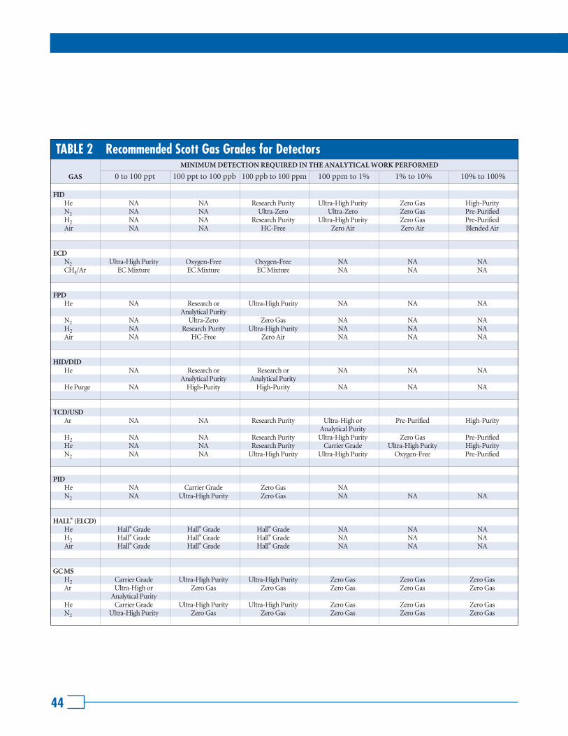
44
MINIMUM DETECTION REQUIRED IN THE ANALYTICAL WORK PERFORMED
GAS 0 to 100 ppt 100 ppt to 100 ppb 100 ppb to 100 ppm 100 ppm to 1% 1% to 10% 10% to 100%
TABLE 2 Recommended Scott Gas Grades for Detectors
FIDHe NA NA Research Purity Ultra-High Purity Zero Gas High-PurityN2 NA NA Ultra-Zero Ultra-Zero Zero Gas Pre-PurifiedH2 NA NA Research Purity Ultra-High Purity Zero Gas Pre-PurifiedAir NA NA HC-Free Zero Air Zero Air Blended Air
ECDN2 Ultra-High Purity Oxygen-Free Oxygen-Free NA NA NACH4/Ar EC Mixture EC Mixture EC Mixture NA NA NA
FPDHe NA Research or Ultra-High Purity NA NA NA
Analytical PurityN2 NA Ultra-Zero Zero Gas NA NA NAH2 NA Research Purity Ultra-High Purity NA NA NAAir NA HC-Free Zero Air NA NA NA
HID/DIDHe NA Research or Research or NA NA NA
Analytical Purity Analytical PurityHe Purge NA High-Purity High-Purity NA NA NA
TCD/USDAr NA NA Research Purity Ultra-High or Pre-Purified High-Purity
Analytical PurityH2 NA NA Research Purity Ultra-High Purity Zero Gas Pre-PurifiedHe NA NA Research Purity Carrier Grade Ultra-High Purity High-PurityN2 NA NA Ultra-High Purity Ultra-High Purity Oxygen-Free Pre-Purified
PIDHe NA Carrier Grade Zero Gas NAN2 NA Ultra-High Purity Zero Gas NA NA NA
HALL® (ELCD)He Hall® Grade Hall® Grade Hall® Grade NA NA NAH2 Hall® Grade Hall® Grade Hall® Grade NA NA NAAir Hall® Grade Hall® Grade Hall® Grade NA NA NA
GC MSH2 Carrier Grade Ultra-High Purity Ultra-High Purity Zero Gas Zero Gas Zero GasAr Ultra-High or Zero Gas Zero Gas Zero Gas Zero Gas Zero Gas
Analytical PurityHe Carrier Grade Ultra-High Purity Ultra-High Purity Zero Gas Zero Gas Zero GasN2 Ultra-High Purity Zero Gas Zero Gas Zero Gas Zero Gas Zero Gas

Design and Safety Handbook
45
MINIMUM DETECTION REQUIRED IN THE ANALYTICAL WORK PERFORMED
GAS 0 to 100 ppt 100 ppt to 100 ppb 100 ppb to 100 ppm 100 ppm to 1% 1% to 10% 10% to 100%
TABLE 2 Recommended Scott Gas Grades for Detectors (continued)
XSDO2 Research Purity Research Purity Research Purity Research Purity Research Purity Research Purity Air VOC Free VOC Free VOC Free Ultra-Zero Ultra-Zero Ultra-Zero
Ambient Zero Ambient Zero Ambient Zero
PFPDN2 Ultra-High Purity Ultra-High Purity Ultra-High Purity Ultra-High Purity Zero Gas Zero GasHe Research Purity Research Grade Carrier Grade Ultra-High Purity Ultra-High Purity Ultra-High PurityH2 Research Purity Carrier Grade Carrier Grade Ultra-High Purity Ultra-High Purity Ultra-High PurityAir Hydrocarbon Free Hydrocarbon Free Hydrocarbon Free Hydrocarbon Free Hydrocarbon Free Hydrocarbon Free
PDPIDAr/He See our Scott See our Scott See our Scott See our Scott See our Scott See our ScottKr/He Reference Reference Reference Reference Reference ReferenceXe/He Guide Guide Guide Guide Guide Guide
PDECDN2 /He See our Scott See our Scott See our Scott See our Scott See our Scott See our ScottCH4 /He Reference Reference Reference Reference Reference ReferenceH2 /He Guide Guide Guide Guide Guide GuideXe/He
PDHIDHe Research Purity Research Purity Carrier Grade Carrier Grade Ultra-High Purity Ultra-High Purity
TSDHe Carrier Grade Carrier Grade Ultra-High Purity Ultra-High Purity Ultra-High Purity Ultra-High PurityN2 Ultra-High Purity Ultra-High Purity Ultra-High Purity Ultra-High Purity Ultra-High Purity Ultra-High PurityH2 Carrier Grade Carrier Grade Carrier Grade Ultra-High Purity Ultra-High Purity Ultra-High PurityAir Zero Air Zero Air Zero Air Zero Air Zero Air Zero Air

46
TABLE 3 Maximum Impurities in Various Scott Grade Gases
GAS GRADE O2 H2O CO2 CO THCHALO-
N2CARBONS
VOC Free 21-20% < 2 ppm < 300 ppb < 50 ppb < 10 ppb
Ultra-Zero 21-20% < 5 ppm 315-385 ppm < 50 ppb < 50 ppb
AIR Hall® Grade**
HC Free 21-20% < 5 ppm < 1 ppm < 500 ppb < 100 ppb
Vehicle Emission Zero 21-20% < 400 ppm < 1 ppm < 1 ppm
Zero 21-20% < 1 ppm
Blended 21-20% < 10 ppm
Research < 200 ppb < 500 ppb < 200 ppb < 100 ppb < 100 ppb <500 ppb
ARGON Ultra-High Purity < 1 ppm < 1 ppm < 1 ppm < 500 ppb <4 ppm
Zero Gas < 500 ppb
Pre-Purified < 3 ppm < 5 ppm
High-Purity
Research Purity < 500 ppb < 200 ppb + CO < 100 ppb < 100 ppb < 1 ppb* <500 ppb
Carrier < 1 ppm < 500 ppb < 500 ppb < 500 ppb <2 ppm
HELIUM Hall® Grade***
Ultra-High Purity < 2 ppm < 1 ppm < 500 ppb
Zero Gas < 500 ppb
High-Purity
Research Purity < 200 ppb < 500 ppb + CO < 100 ppb < 100 ppb <300 ppb
Carrier Grade < 500 ppb < 2 ppm < 100 ppb < 200 ppb < 200 ppb <2 ppm
HYDROGEN Hall® Grade ▲
Ultra-High Purity < 1 ppm < 500 ppb < 500 ppb < 500 ppb <5 ppm
Zero Gas < 500 ppb
Pre-Purified
VOC Free < 2 ppm < 2 ppm < 300 ppb < 100 ppb < 50 ppb
Ultra-High Purity < 500 ppb < 2 ppm < 1 ppm < 1 ppm < 500 ppb < 1 ppb*
NITROGEN Vehicle Emission Zero < 1 ppm < 1 ppm < 1 ppm
Ultra Zero < 2 ppm < 4 ppm < 1 ppm < 100 ppb < 50 ppb
Oxygen Free < 500 ppb
Zero Gas < 500 ppb
Pre-Purified < 5 ppm < 4 ppm
ECD 5% VOC Grade < 1 ppm < 1 ppm < 1 ppm < 1 ppm < 500 ppt
CH4 in Ar UHP < 1 ppm < 1 ppm < 1 ppm < 1 ppb*
* Specify individual cylinder analysis for total Halocarbons when placing your order. ** Specifically manufactured for use with the Tracor Hall® Electrolytic Conductivity Detector in the Sulfur Mode.
*** Specifically manufactured for use with the Tracor Hall® Electrolytic Conductivity Detector in both the Halogen and Sulfur Mode.▲ Specifically manufactured for use with the Tracor Hall® Electrolytic Conductivity Detector in the Halogen Mode.

Design and Safety Handbook
47
NDIR
(CO, CO2, SO2) N2 Ultra-Zero Ultra-Zero Zero Gas Pre-Purified
Air Ultra-Zero Ultra-Zero Zero Air Blended Air
CHEMILUMINESCENCE
(NO, NO2) N2 Ultra-Zero Ultra-High Purity Zero Gas N/A
Air Ultra-Zero Ultra-Zero N/A N/A
PULSE FLUORESCENCE
(SO2) N2 Ultra-Zero Ultra-Zero Zero Gas N/A
Air Ultra-Zero Ultra-Zero Blended Air N/A
UV PHOTOMETRY
(SO2, O3) N2 N/A N/A Pre-Purified N/A
Air N/A Zero Air Blended Air N/A
PARAMAGNETIC
(O2) N2 N/A N/A Oxygen-Free Pre-Purified
Air N/A N/A N/A N/A
ELECTROCHEMICAL SENSORS
(H2S, NO, NO2, SO2) N2 Ultra-Zero Zero Gas Pre-Purified N/A
Air Ultra-Zero Zero Air Blended Air N/A
SEMICONDUCTOR SENSORS
(LFL Measurements) N2 N/A N/A Pre-Purified N/A
Air N/A N/A Blended Air Blended Air
MINIMUM DETECTION REQUIRED IN THE ANALYTICAL WORK PERFORMED
GAS ANALYSIS INSTRUMENTS GAS 10 ppb to 1 ppm 1 ppm to 100 ppm 100 ppm to 1% 1% to 100%
TABLE 4 Recommended Scott Pure Gas Grades for Other Gas Analysis Instrumentation

48
TABLE 5 Listing of Specialty Gases by Category
Acetylene (2) 2.5 – 100
Air X X
Allene X 2.2 – N.A.
Ammonia X 15 – 28 X
Argon X X
Arsine X 5.1 – 78 (4)
Boron Trichloride X X X
Boron Trifluoride X X X (4)
1,3-Butadiene (5) 2.0 – 11.5
Butane X 1.8 – 8.4
Butenes X 1.6 – 10
Carbon Dioxide X X
Carbon Monoxide X 12.5 – 74 X
Carbonyl Sulfide X 11.9 – 28.5 (3) X
Chlorine X X (3) (4)
Cyanogen X 6.6 – 32 (4)
Cyclopropane X 2.4 – 10.4
Deuterium X 4.9 – 75
Diborane X 0.8 – 98 (4)
Dimethylamine X 2.8 – 14.4 X
Dimethyl Ether X 3.4 – 27
Ethane X 3.0 – 12.4
Ethyl Acetylene X (7)
Ethyl Chloride X 3.8 – 15.4
Ethylene X 2.7 – 36
Ethylene Oxide (6) 3.6 – 100 X
Fluorine X X (4)
Germane X (7) (4)
Helium X X
Hydrogen X 4.0 – 75
Hydrogen Bromide X (3) (4)
Hydrogen Chloride X (3) (4)
Hydrogen Fluoride X X (4)
Hydrogen Sulfide X 4 – 44 (3) (4)
Iso-Butane X 1.8 – 9.6
(1) Flammable limits are at normal atmospheric pressure and temperature. Other conditions will change the limits.(2) Dissolved in solvent under pressure. Gas may be unstable and explosive above 15 psig (1 bar).(3) Corrosive in presence of moisture.(4) Toxic. It is recommended that the user be thoroughly familiar with the toxicity and other properties of this gas.(5) Cancer suspect agent.(6) Recognized human carcinogen.(7) Flammable. However, limits are not known.(8) The flammable limits in air for some components are set at different levels in Europe – please refer to Chemiekaarten for specified limitations of each gas.
GAS NO
NL
IQU
EF
IED
C
OM
PR
ES
SE
D G
AS
LIQ
UE
FIE
D G
AS
FL
AM
MA
BL
EL
IMIT
S I
N A
IR
(1),
(8
) V
OL
. (%
)
OX
IDA
NT
INE
RT
CO
RR
OS
IVE
TO
XIC

Design and Safety Handbook
TABLE 5 Listing of Specialty Gases by Category (Continued)
Iso-Butylene X 1.8 – 9.6
Krypton X X
Methane X 5.0 – 15.0
Methyl Chloride X 10.7 – 17.4
Methyl Mercaptan X 3.9 – 22 (4)
Monoethylamine X 3.5 – 14 X
Monomethylamine X 4.9 – 20.7 X
Neon X X
Nitric Oxide X X (3) (4)
Nitrogen X X
Nitrogen Dioxide X X (3) (4)
Nitrogen Trioxide X X (3) (4)
Nitrosyl Chloride X X (3) (4)
Nitrous Oxide X X
Oxygen X X
Phosgene X (4)
Phosphine X 1.6 – 99 (4)
Propane X 2.1 – 9.5
Propylene X 2.0 – 11
Halocarbon-12 X X
(Dichlorodifluoromethane)
Halocarbon-13 X X
(Chlorotrifluoromethane)
Halocarbon-14 X X
(Tetrafluoromethane)
Halocarbon-22 X X
(Chlorodifluoromethane)
Silane X 1.5 – 98
Sulfur Dioxide X (3) (4)
Sulfur Hexafluoride X X
Sulfur Tetrafluoride X X (4)
Trimethylamine X 2.0 – 12.0 X
Vinyl Bromide X 9 – 15
Vinyl Chloride (5) 3.6 – 33
Xenon X X
(1) Flammable limits are at normal atmospheric pressure and temperature. Other conditions will change the limits.(2) Dissolved in solvent under pressure. Gas may be unstable and explosive above 15 psig (1 bar).(3) Corrosive in presence of moisture.(4) Toxic. It is recommended that the user be thoroughly familiar with the toxicity and other properties of this gas.(5) Cancer suspect agent.(6) Recognized human carcinogen.(7) Flammable. However, limits are not known.(8) The flammable limits in air for some components are set at different levels in Europe – please refer to Chemiekaarten for specified limitations of each gas.
GAS NO
NL
IQU
EF
IED
C
OM
PR
ES
SE
D G
AS
LIQ
UE
FIE
D G
AS
FL
AM
MA
BL
EL
IMIT
S I
N A
IR
(1),
(8
) V
OL
. (%
)
OX
IDA
NT
INE
RT
CO
RR
OS
IVE
TO
XIC
49

50
NONCORROSIVE
Acetylene C2H2 • • • • • • •Air • • • • • • • • •Argon Ar • • • • • •1,3-Butadiene C4H6 • • • • • •Butane C4H10 • • • • • • • •Carbon Dioxide CO2 • • • • • •Cyclopropane C3H6 • • • • • •Deuterium D2 • • • • • •Ethane C2H6 • • • • • • •Ethylene C2H4 • • • • • • • •Helium He • • • • • • • •Hydrogen H2 • • • • • • •Isobutane CH(CH3)3 • • • • • •Krypton Kr • • • • • •Methane CH4 • • • • • • • •Neon Ne • • • • • •Nitrogen N2 • • • • • • •Nitrous Oxide N2O • • • • • •Oxygen O2 • • • • • • •Propane C3H8 • • • • • • • •Propylene C3H6 • • • • • • • •Silane SiH4 • • • • • • • • •Sulfur Hexafluoride SF6 • • • • • •Xenon Xe • • • • • •
MILDLY CORROSIVE
Ammonia NH3 • • • • •Carbon Monoxide CO • • • • • •Hydrogen Sulfide H2S • • • •Hydrogen Selenide H2Se • • • •Sulfur Dioxide SO2 • • • • •Vinyl Chloride C2H3Cl • ▲ ** • •
CORROSIVE
Chlorine Cl2 • • • • •Hydrogen Chloride HCl • • • • •Nitric Oxide NO • • • • • •Nitrogen Dioxide NO2 • • • • • •
• Designates acceptable compatibility.** The stainless steel recommendation is for gas mixtures only.▲ Copper content in Vinyl Chloride must be 70% or lower for brass.
TABLE 6 Material Compatibility Guide
CHEMICALGAS SERVICE FORMULA A
LU
MIN
UM
BR
AS
S
ST
AIN
LE
SS
ST
EE
L
MO
NE
L®
NIC
KE
L
BU
NA
-N
PC
TF
E
NE
OP
RE
NE
TE
FL
ON
®
VIT
ON
®
NY
LO
N

Design and Safety Handbook
51
GENERAL DEFINITIONS AND TERMINOLOGY
Absolute Pressure – A quantity of pressure measured with respect to total vacuum. Equal to the sum of a pressure gauge reading and atmospheric pressure (14.69 psia or 1.01 bar at sea level).
Absorption – The "soaking up" of gas, liquids or dissolved substances into a solid material.
Acid – A chemical compound that dissociates in aqueous solution to form hydrogen ions; a proton donor that reacts with a base to form a salt.
Adsorption – The condensation of gas, liquids or dissolved substances on the surface of solids.
Aerobic Gas Mixture – Gas mixture containing oxygen; used for incubation of microorganismsthat require oxygen for life.
Air – The mixture of gases that surrounds the earth. The composition of air is 78.08% nitrogen,20.95% oxygen, 0.03% carbon dioxide, and 0.93% argon. Standard air has a density of 0.075 lb/ft
3
(1.2 kg/m3
) measured dry at 70°F (21°C) and 760 mm Hg pressure, M.W. 28.3.
Anaerobic Gas Mixture – A gas mixture containing no oxygen, used for incubation of microor-ganisms that do not require free oxygen for life.
Anhydrous – A descriptive term meaning without water.
Auto Ignition Temperature – The minimum temperature at which a substance will ignite in the airwhen there is no ignition source. For liquids, it is defined as the lowest temperature at which a dropof solvent will ignite spontaneously.
Balance Gas – A gas used to “top off” a gas mixture after individual component gases at specifiedconcentrations are added.
Base – A chemical compound that can react with an acid to form a salt.
Boiling Point – The temperature at which the vapor pressure of a liquid equals the atmosphericpressure (usually given at 760 mm Hg).
BS – Short for British Standard. A standard from the British Standards Institution. BS 341 recommends cylinder valve outlet connections for specific gas services based upon safety considerations.
Calibration Gas – A gas of accurately known concentration that is used as a comparative standardin analytical instrumentation.
Carrier Gas – Pure gases or gas mixtures used to move a sample to be analyzed through the gasanalysis system at an even rate and provide a zero reference (baseline) when a sample is not beingdetected.
Caution – A term used in precautionary labeling to denote a lower degree of hazard than the terms“danger” or “warning.”
DEFINITIONS AND TERMINOLOGY

52
CGA – Short for Compressed Gas Association, an association that recommends cylinder valve outlet connections for specific gas services based on safety considerations.
Compressed Gas – Any material or mixture having in the container either an absolute pressureexceeding 40 psia (3 bar) at 70°F (21°C) or an absolute pressure exceeding 104 psia (7 bar) at 130°F (54°C).
Compressed Gas in Solution – A nonliquefied compressed gas that is dissolved in a solvent.
Corrosive – Gases that corrode material or tissue with which they come in contact, or do so in the presence of water, are classified as corrosive. It is essential that equipment used for handling corrosive gases be constructed of proper materials. Proper protective clothing and equipment mustbe used to minimize exposure to corrosive materials.
Critical Pressure – The pressure required to liquefy a gas at the critical temperature.
Critical Temperature – The temperature above which a gas cannot be liquefied by pressure alone.
Cylinder – A pressure vessel designed for pressure higher than 40 psia (3 bar) and having a circular cross-section.
Danger – A term denoting the highest degree of hazard.
Desorption – The leaching out of gas, liquids or dissolved substances from solid material.
DIN – Deutsche Norm. A standard from the Deutsches Institut fur Normung. DIN 477 recommends cylinder valve outlet connections for specific gas services based upon safety considerations.
Explosion Proof – An enclosure for an electrical apparatus so designed that an explosion of flammable gas or vapor inside the enclosure will not ignite flammablegas or vapor outside.
FID – Flame ionization detector.
FID Fuels – Hydrogen-nitrogen and hydrogen-helium mixtures burned as a source of heat and power in FIDs.
Flammable – A substance that will ignite easily and burn rapidly in the presence of an oxidizer.
Flashback – The phenomenon characterized by vapor ignition and flame travelback to the vapor source.
GC – Gas chromatograph.
Impurity – Amount of foreign material or contaminants found in a pure material.
Inert – Gases that do not react with other materials under normal temperature and pressure.
Liquefied Compressed Gas – A gas that is partially liquid at its charging pressure and a temperature of 70°F (21°C).
Gas Chromatograph

Design and Safety Handbook
53
Mole – Mass numerically equal to its molecular weight. A gram mole is the weight in grams equal to the molecular weight.
Molecular Weight – The sum of the atomic weights of all the constituent atoms in a molecule.
NEN – Nederlandse Norm. A standard from the Dutch Normalisation Institute. NEN 3260 recommends cylinder valve outlet connections for specific gas services based upon safety considerations.
Nonliquefied Compressed Gas – A “nonliquefied compressed gas” is a gas, other than gas in solu-tion, that under the charged pressure is entirely gaseous at a temperature of 70°F (21°C).
NTP – Normal temperature and pressure, 20°C and 760 torr.
Off-gassing – The removal of gas, liquids or dissolved substances from the surface of solids.
Oxidant – A gas that does not burn but will support combustion.
Partial Pressure – In any gas mixture, the total pressure is equal to the sum of the pressures (partial) that each gas would exert were it alone in the volume occupied by the mixture.
PPM – Parts per million.
PPB – Parts per billion.
PPT – Parts per trillion.
Pyrophoric – Materials that spontaneously ignite on contact with air at normal conditions.
Specific Gravity – The ratio of the weight of any volume to the weight of an equal volume of another substance taken as a standard. For solids or liquids, the standard is usually water and for gases, the standard is air.
Specific Heat – The amount of heat required to raise the unit weight of a substance one degree of temperature at constant pressure.
Specific Volume – The volume of a unit weight of a substance at a given temperature.
STP – Standard temperature and pressure, 0°C and 760 torr.
Sublimation – The process of passing from a solid state directly to a gaseous state.
TLV – Threshold Limit Value, the time-weighted average concentration of an airborne substancethat represents the condition under which it is believed nearly all workers may be exposed in a normal eight-hour day, five-day work week without suffering adverse effect.
Toxic Gas – Gases that may chemically produce injurious or lethal effects to humans.
Vapor Pressure – The pressure exerted when a solid or a liquid is in equilibrium with its ownvapor at a particular temperature.
Warning – A term indicating an intermediate degree of hazard in precautionary labeling between“danger” and “caution.”

54
CYLINDER SIZEDOT
SPEC.LITERS CU. FT.
INTERNAL VOLUME@ 70°F (21°C), 1 ATMWATER
CAPACITY(LBS.)
NOMINAL*TARE WEIGHT
(LBS.)
NOMINAL*DIMENSIONSDIA. X LGTH.
(INCHES)
* Includes 5.5 inches or 4.5 lbs. for valve and cap.
K 9.25 X 60 135 110 49.9 1.76 3AA2400
A 9 X 56 114 96 43.8 1.55 3AA2015
B 8.5 X 31 60 37.9 17.2 0.61 3AA2015
C 6 X 24 27 15.2 6.88 0.24 3AA2015
D 4 X 18 12 4.9 2.24 0.08 3AA2015
AL 8 X 53 52 64.8 29.5 1.04 3AL2015
BL 7.25 X 39 33 34.6 15.7 0.55 3AL2216
CL 7.25 X 21 19 13.0 5.90 0.21 3AL2216
XL 14.5 X 50 75 238 108 3.83 4BA240
SSB 8 X 37 95 41.6 18.9 0.67 3A1800
10 S 4 X 31 21 8.3 3.8 0.13 3A1800
LB 2 X 15 4 1.0 0.44 0.016 3E1800
XF 12 X 46 180 — 60.9 2.15 8AL
XG 15 X 56 149 278 126.3 4.46 4AA480
XM 10 X 49 90 120 54.3 1.92 3A480
XP 10 X 55 55 124 55.7 1.98 4BA300
K A B C D AL BL CL SSB 10S LB XG XM XP XF XLHigh Pressure Low Pressure
TABLE 9 Typical DOT Cylinder Specifications

Design and Safety Handbook
LB 1 2 3 5 10 20 50(LB = 0.47 liter) water capacity (liter)
High Pressure
55
50 50 229 1530 66
20 20 204 1060 25.5
10 10 140 825 13.4
5 5 140 445 5.9
50L 50 250 1510 56.7
20L 20 191 1060 23.6
10L 10 176 660 12.8
5L 5 152 465 7.20
50H 50 229 1530 66
20H 20 204 1060 25.5
10H 10 140 825 13.4
5H 5 102 445 5.9
LB 0.47 61 265 1.4
TABLE 10 Typical EEC Cylinder Specifications
CYLINDER SIZE
WEIGHT EXCLUDING CAP
& VALVE (kg)
HEIGHT EXCLUDING CAP
& VALVE (mm)
OUTSIDE DIAMETER
(mm)
WATER CAPACITY
(LITERS)

Scott Specialty Gases
Corporate Headquarters6141 Easton RoadP.O. Box 310Plumsteadville, PA 18949-0310Phone: 215-766-8861Fax: 215-766-0320
European HeadquartersTakkebijsters 484817 BL BredaThe Netherlands+31 76 5711828
Philadelphia Area6141 Easton Rd.P.O. Box 310Plumsteadville, PA 18949-0310Phone: 215-766-7221
New York City Area2330 Hamilton BoulevardSouth Plainfield, NJ 07080Phone: 908-754-7700
Raleigh/Durham Area1750 East Club Blvd.Durham, NC 27704Phone: 919-220-0803
Salt Lake City Area23 South CenterAmerican Fork, UT 84003Phone: 801-763-8699
Boston Area419 Main St. Suite 202Wakefield, MA 01880Phone: 781-245-8788
Detroit Area1290 Combermere StreetTroy, MI 48083Phone: 248-589-2950
Denver Area500 Weaver Park RoadLongmont, CO 80501Phone: 303-442-4700
Houston Area9810 Bay Area BoulevardPasadena, TX 77507Phone: 281-474-5800
Chicago Area858 Sivert DriveWoodDale, IL 60191Phone: 630-860-1824
San Francisco Area5121 Brandin CourtFremont, CA 94538Phone: 510-659-0162
Los Angeles Area2600 Cajon BoulevardSan Bernardino, CA 92411Phone: 909-887-2571
United KingdomUnit 5, Speedwell RoadParkhouse EastNew Castle-under-Lyme,Staffordshire ST5 7RGUnited KingdomPhone: +44 1782 561500
Teflon® and Tefzel® are registered trademarks of E. I. DuPont de Nemours & Company.Hall® is a registered trademark of Tracor Instruments.Monel® is a registered trademark of Inco Alloys International Inc.Snoop® is a registered trademark of Nupro Company.Viton® is a registered trademark of DuPont Dow Elastomers.
Reproduction of this handbook either in whole or in part without written permission
from Scott Specialty Gases is prohibited.
Published by Scott Specialty Gases 3001.2
Printed in USA ©2000 Scott Specialty Gases 5/00-OI-8M
1-800-21 SCOTT Visit our web site: www.scottgas.com
ORDER
ON
-LIN
E• W
WW.SCOTTGAS.COM