Design Options for Locating Ducts within Conditioned Space · Design Options for Locating Ducts...
34
© 2012 Steven Winter Associates, Inc. All rights reserved. Design Options for Locating Ducts within Conditioned Space Bill Zoeller, RA Steven Winter Assoc. Inc. [email protected]
Transcript of Design Options for Locating Ducts within Conditioned Space · Design Options for Locating Ducts...

© 2012 Steven Winter Associates, Inc. All rights reserved.
Design Options for Locating Ducts within Conditioned Space
Bill Zoeller, RA Steven Winter Assoc. Inc.

© 2012 Steven Winter Associates, Inc. All rights reserved.
Why Ducts in Cond. Space?
• Significant Thermal Losses: – Thermal losses triple for ducts in unconditioned vs.
conditioned space – Total thermal losses can range from 10-45% – Extensive unconditioned space penetrations
• Significant Performance Impacts: – IAQ – Comfort – Durability
© 2012 Steven Winter Associates, Inc. All rights reserved.
Available Options
Multiple Interior duct options exist
Selecting the “best” option depends on multiple factors…

© 2012 Steven Winter Associates, Inc. All rights reserved.
Option: Ducts in Unvented Attic
By moving the thermal boundary from the ceiling plane up to the roof plane, additional interior volume is created allowing the placement of HVAC equipment and ducts within the conditioned space
© 2012 Steven Winter Associates, Inc. All rights reserved.
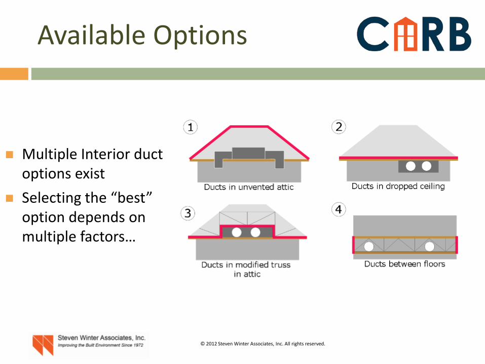
Option: Ducts in Unvented Attic
This method of protecting the HVAC is well suited for retrofits when relocating existing equipment is impractical
Storage is not code-allowed in these spaces without the use of thermal and ignition barriers (more in a moment)
© 2012 Steven Winter Associates, Inc. All rights reserved.
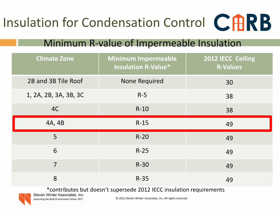
Minimum R-value of Impermeable Insulation Climate Zone Minimum Impermeable
Insulation R-Value* 2012 IECC Ceiling
R-Values
2B and 3B Tile Roof None Required 30
1, 2A, 2B, 3A, 3B, 3C R-5 38
4C R-10 38
4A, 4B R-15 49
5 R-20 49
6 R-25 49
7 R-30 49
8 R-35 49 *contributes but doesn’t supersede 2012 IECC insulation requirements
Insulation for Condensation Control
© 2012 Steven Winter Associates, Inc. All rights reserved.
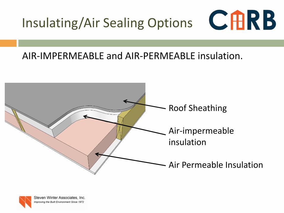
AIR-IMPERMEABLE and AIR-PERMEABLE insulation.
Roof Sheathing Air-impermeable insulation Air Permeable Insulation
Insulating/Air Sealing Options

© 2012 Steven Winter Associates, Inc. All rights reserved.
Provides option for AHU placement as well as ducts
Not as plan-dependent as other options
Viable for retrofits
Often the highest cost option Code limitations/requirements
on roof deck insulation Increases heating/cooling loads
by increasing surface area of thermal boundary
Option: Ducts in Unvented Attic
IRC Sections R806.4 Unvented Attic Assemblies, and R316 FOAM PLASTIC control these assemblies
Advantages and Limitations

© 2012 Steven Winter Associates, Inc. All rights reserved.
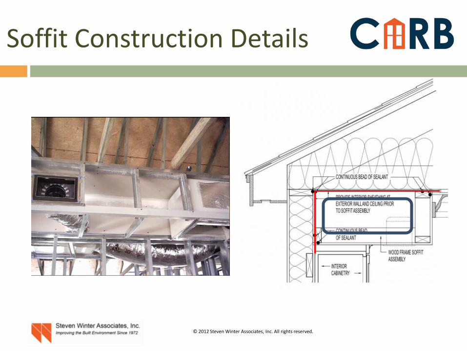
Option: Ducts in Dropped Soffit
Ducts are placed in soffits and dropped ceilings below the primary ceiling plane level
Architectural integration and aesthetics are critical considerations

© 2012 Steven Winter Associates, Inc. All rights reserved.
Dropped Soffit Configuration
© 2012 Steven Winter Associates, Inc. All rights reserved.
Soffit Construction Details
© 2012 Steven Winter Associates, Inc. All rights reserved.
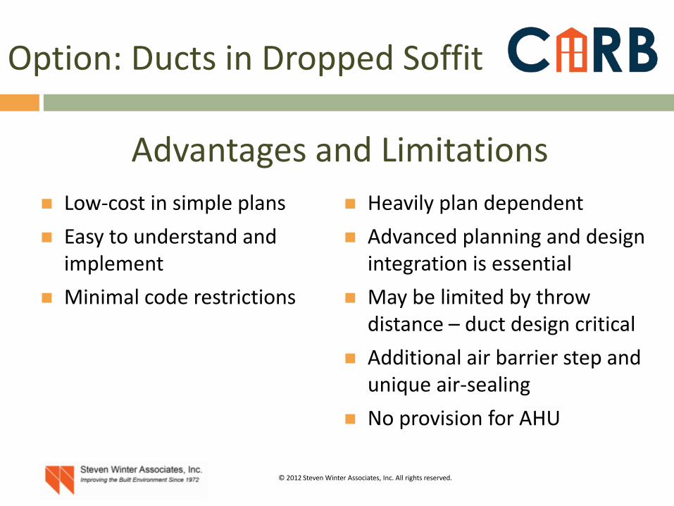
Low-cost in simple plans Easy to understand and
implement Minimal code restrictions
Heavily plan dependent Advanced planning and design
integration is essential May be limited by throw
distance – duct design critical Additional air barrier step and
unique air-sealing No provision for AHU
Option: Ducts in Dropped Soffit
Advantages and Limitations
© 2012 Steven Winter Associates, Inc. All rights reserved.
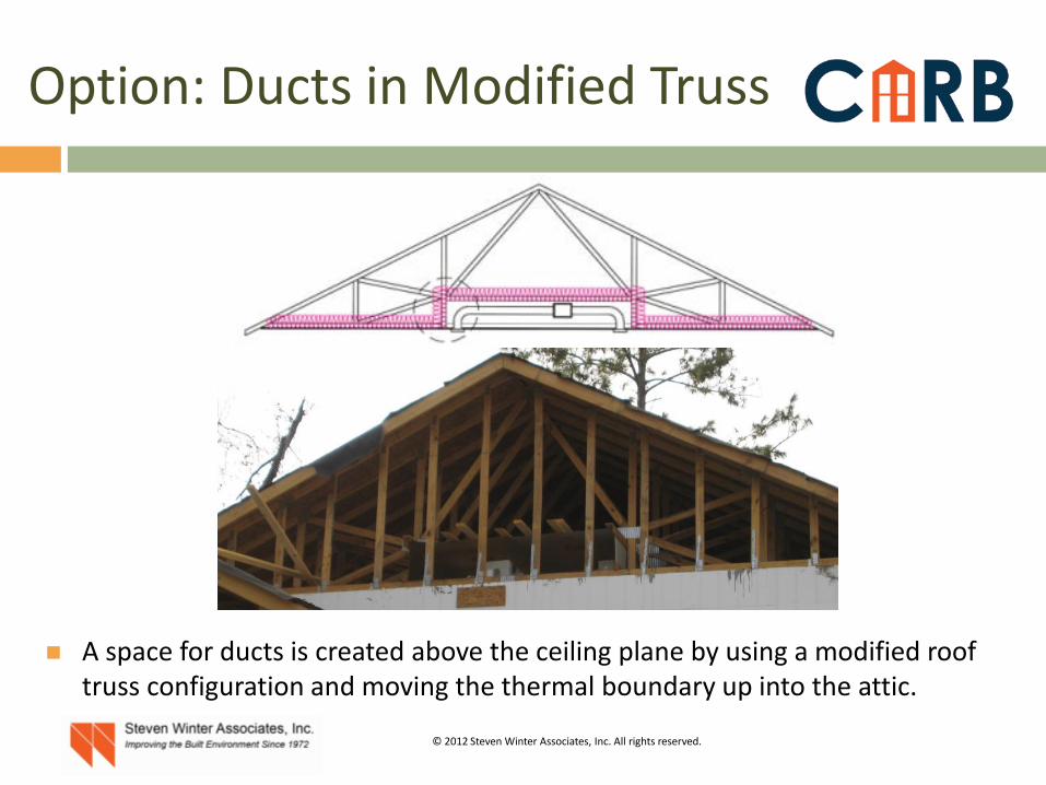
Option: Ducts in Modified Truss
A space for ducts is created above the ceiling plane by using a modified roof truss configuration and moving the thermal boundary up into the attic.

© 2012 Steven Winter Associates, Inc. All rights reserved.
Option: Ducts in Modified Truss

© 2012 Steven Winter Associates, Inc. All rights reserved.
Option: Ducts in Modified Truss
Plenum space area

© 2012 Steven Winter Associates, Inc. All rights reserved.
Modified Scissor Truss Method
Plenum Truss Detail

© 2012 Steven Winter Associates, Inc. All rights reserved.
Option: Ducts in Modified Truss

© 2012 Steven Winter Associates, Inc. All rights reserved.
Low-cost in simple plans Not as plan dependent
as dropped soffit solution
Minimal code restrictions
Works best in linear plans
Additional air-barrier and unique air-sealing
Requires custom, non-standard roof trusses
No provision for AHU
Option: Ducts in Modified Truss
Advantages and Limitations
© 2012 Steven Winter Associates, Inc. All rights reserved.
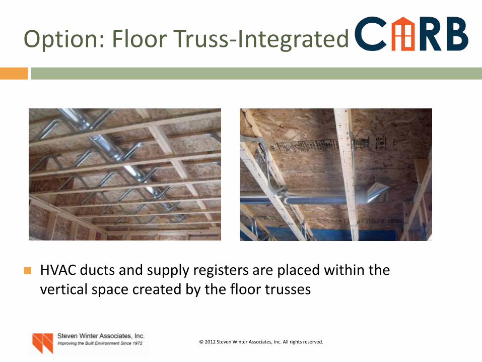
Option: Floor Truss-Integrated Ducts
HVAC ducts and supply registers are placed within the vertical space created by the floor trusses
© 2012 Steven Winter Associates, Inc. All rights reserved.
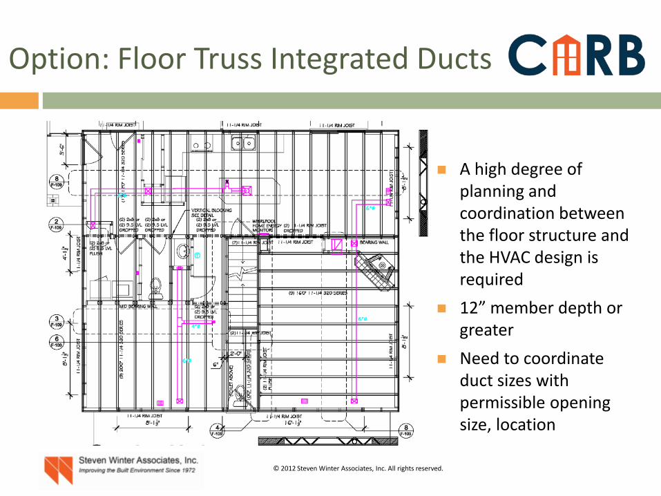
Option: Floor Truss Integrated Ducts
A high degree of planning and coordination between the floor structure and the HVAC design is required
12” member depth or greater
Need to coordinate duct sizes with permissible opening size, location

© 2012 Steven Winter Associates, Inc. All rights reserved.
Option: Floor Truss Integrated Ducts
Ceiling registers blowing down and floor registers blowing up can be used. High wall registers are better than floor registers for cooling and can also be accommodated.
© 2012 Steven Winter Associates, Inc. All rights reserved.
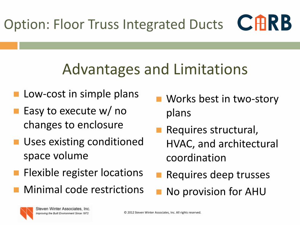
Low-cost in simple plans Easy to execute w/ no
changes to enclosure Uses existing conditioned
space volume Flexible register locations Minimal code restrictions
Works best in two-story plans
Requires structural, HVAC, and architectural coordination
Requires deep trusses No provision for AHU
Option: Floor Truss Integrated Ducts
Advantages and Limitations

© 2012 Steven Winter Associates, Inc. All rights reserved.
Option: Ducts in Sealed Crawlspace
Bring the crawlspace (or basement) inside conditioned space and use the volume to place HVAC equipment and ducts

© 2012 Steven Winter Associates, Inc. All rights reserved.
Option: Ducts in Sealed Crawlspace
Advantages and Limitations Improves enclosure
performance Accommodates AHU and
other equipment Flexible register locations HVAC/ducts accessible for
service
Code thermal insulation requirements
Code mechanical ventilation requirements

© 2012 Steven Winter Associates, Inc. All rights reserved.
Option: Buried Ducts
Low cost, high-performance duct strategy Very high R-values

© 2012 Steven Winter Associates, Inc. All rights reserved.
Proof of Concept Testing
© 2012 Steven Winter Associates, Inc. All rights reserved.
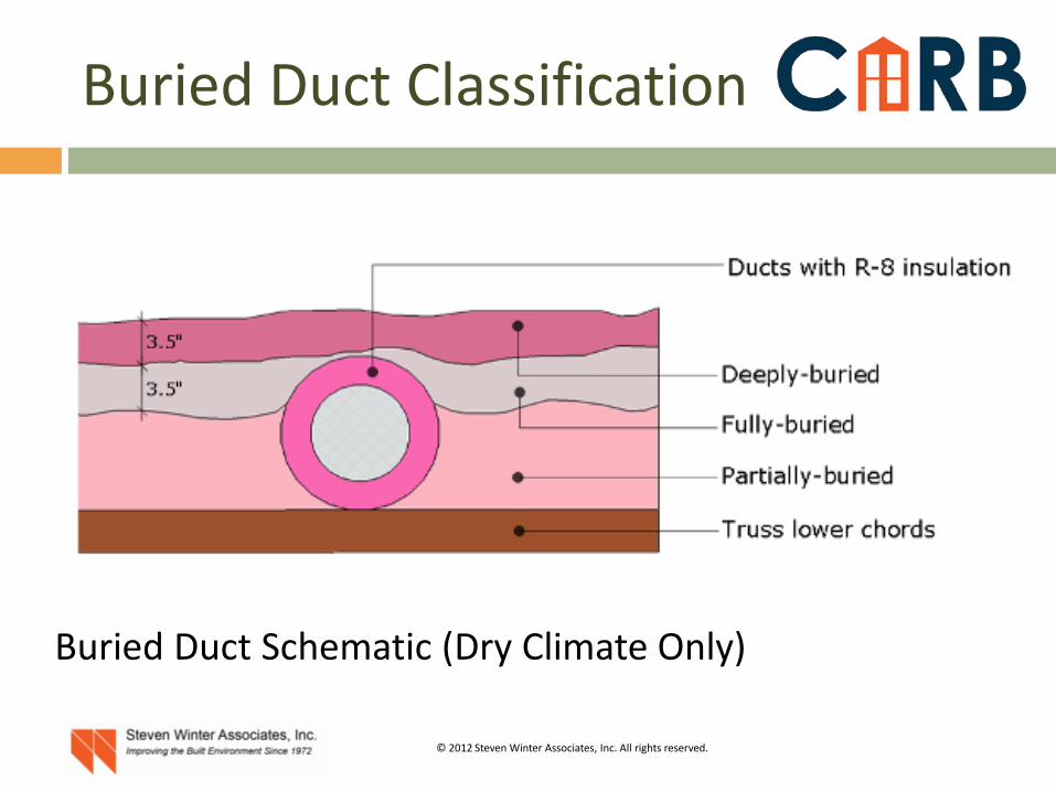
Buried Duct Classification
Buried Duct Schematic (Dry Climate Only)

© 2012 Steven Winter Associates, Inc. All rights reserved.
Buried Duct Classification
Buried & Encapsulated Duct Schematic (All Climates)

© 2012 Steven Winter Associates, Inc. All rights reserved.
Finite Element Method
Table 1. Effective R-values of RSI-1.4 (RUS-8.0) Ducts by Insulation Strategy, m2-K/W (hr-ft2-°F/Btu) Duct
Diameter, mm (in)
Insulated Round
Encapsulated with 38 mm
(1.5 in) of ccSPF
Buried (Not Encapsulated) Buried & Encapsulated with 38 mm (1.5 in) of ccSPF
Partially Fully Deeply Partially Fully Deeply 100 (4) 1.05 (6.0) 1.74 (9.9) 1.5 (8.8) 2.1 (12.0) 3.2 (17.9) 2.5 (14.4) 3.1 (17.5) 4.0 (22.7) 150 (6) 1.18 (6.7) 2.04 (11.6) 1.9 (10.9) 2.6 (14.9) 4.0 (22.6) 3.2 (18.1) 3.9 (22.0) 5.1 (28.7) 200 (8) 1.26 (7.2) 2.24 (12.7) 2.2 (12.6) 3.0 (17.3) 4.6 (26.4) 3.7 (21.1) 4.5 (25.6) 5.9 (33.6) 250 (10) 1.32 (7.5) 2.40 (13.6) 2.5 (14.2) 3.4 (19.3) 5.2 (29.6) 4.2 (23.7) 5.1 (28.7) 6.7 (37.8) 300 (12) 1.36 (7.7) 2.51 (14.3) 2.7 (15.5) 3.7 (21.1) 5.7 (32.5) 4.6 (26.0) 5.5 (31.5) 7.3 (41.4) 350 (14) 1.39 (7.9) 2.61 (14.8) 2.9 (16.7) 4.0 (22.7) 6.2 (35.0) 4.9 (28.0) 6.0 (33.9) 7.9 (44.7) 400 (16) 1.42 (8.0) 2.68 (15.2) 3.1 (17.8) 4.3 (24.2) 6.6 (37.4) 5.3 (29.9) 6.4 (36.1) 8.4 (47.7)
Newton Method Mesh Temperature Distribution Heat Flux Magnitude

© 2012 Steven Winter Associates, Inc. All rights reserved.
Install Low-Profile, Compact Duct Design
Before ceiling drywall After ceiling drywall

© 2012 Steven Winter Associates, Inc. All rights reserved.
Apply 1.5” minimum ccSPF
Apply min. 1.5” ccSPF prior to or after ceiling gypsum board

© 2012 Steven Winter Associates, Inc. All rights reserved.
Install Loose-fill insulation
Insulation must be ASTM classified as “mineral-fiber”, and must cover the ccSPF by a minimum of 1.5” (cellulose doesn’t qualify)
Some foams are exempt from this requirement (more in a moment)

© 2012 Steven Winter Associates, Inc. All rights reserved.
Low-cost in simple plans Easy to execute w/ no
changes to enclosure Minimal plan coordination Flexible register location 2009 IRC compliant
Sections R316.5.3, M1601.3
Requires HVAC design coordination
No provision for AHU
Option: Buried / Encapsulated Ducts
Advantages and Limitations

© 2012 Steven Winter Associates, Inc. All rights reserved.
Steven Winter Associates, Inc. 61 Washington St. Norwalk, CT 06854 203-857-0200 Bill Zoeller [email protected]
Contact Info