Design of Semi gravity Retaining Walls - WEC...
59
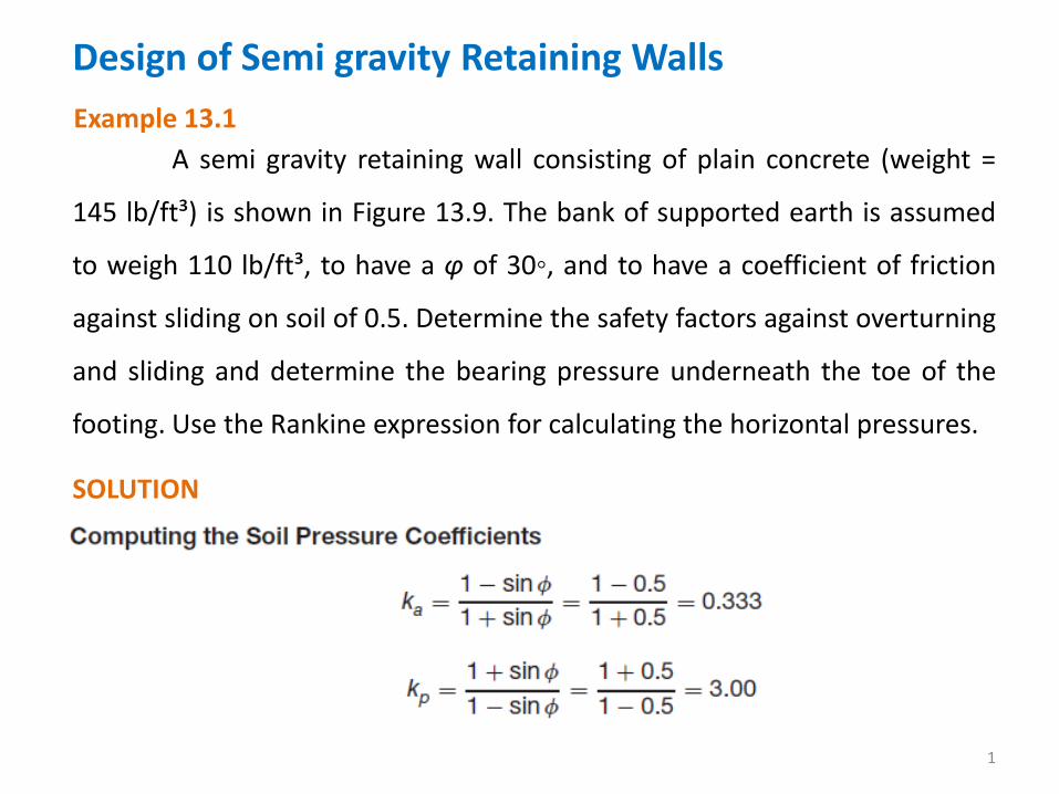
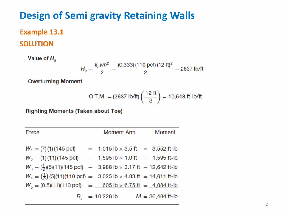
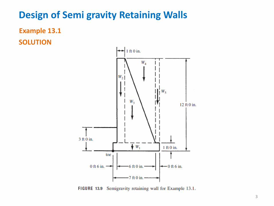
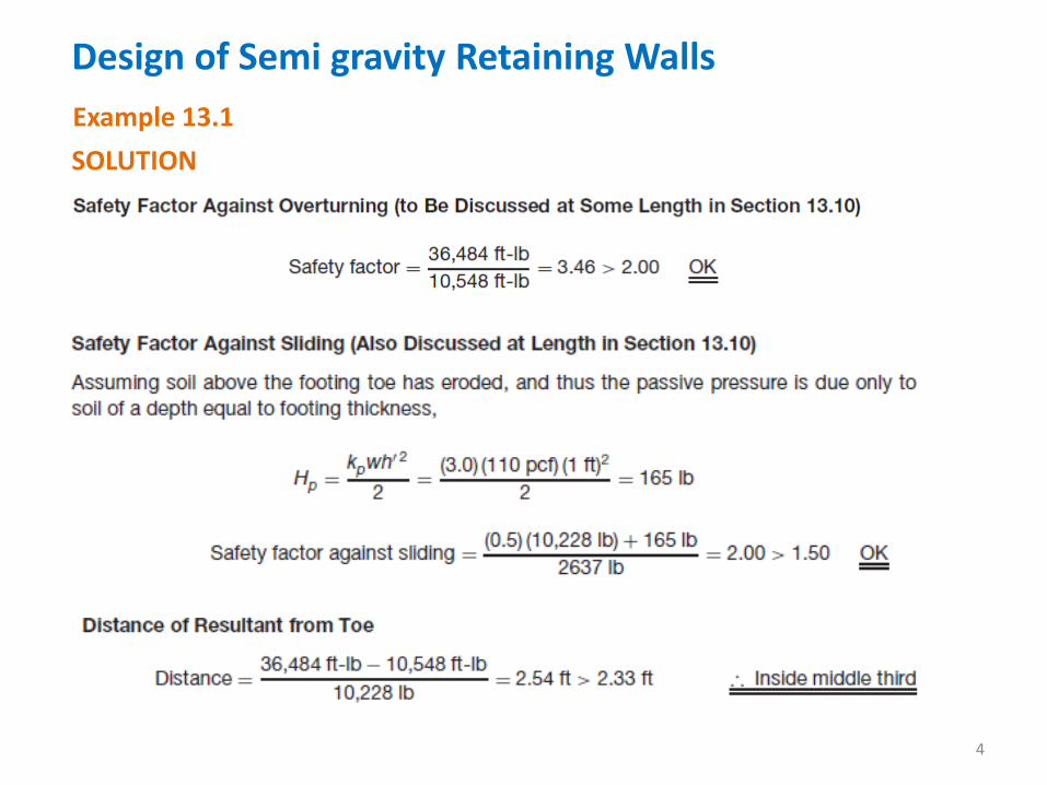
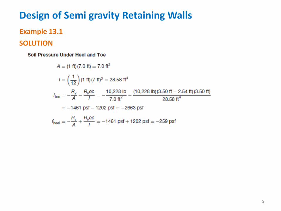
Design of Semi gravity Retaining Walls 1 A semi gravity retaining wall consisting of plain concrete (weight = 145 lb/ft³) is shown in Figure 13.9. The bank of supported earth is assumed to weigh 110 lb/ft³, to have a φ of 30◦, and to have a coefficient of friction against sliding on soil of 0.5. Determine the safety factors against overturning and sliding and determine the bearing pressure underneath the toe of the footing. Use the Rankine expression for calculating the horizontal pressures. SOLUTION Example 13.1
Transcript of Design of Semi gravity Retaining Walls - WEC...
Design of Semi gravity Retaining Walls
1
A semi gravity retaining wall consisting of plain concrete (weight =
145 lb/ft³) is shown in Figure 13.9. The bank of supported earth is assumed
to weigh 110 lb/ft³, to have a φ of 30◦, and to have a coefficient of friction
against sliding on soil of 0.5. Determine the safety factors against overturning
and sliding and determine the bearing pressure underneath the toe of the
footing. Use the Rankine expression for calculating the horizontal pressures.
SOLUTION
Example 13.1
Design of Semi gravity Retaining Walls
2
SOLUTION
Example 13.1
Design of Semi gravity Retaining Walls
3
SOLUTION
Example 13.1
Design of Semi gravity Retaining Walls
4
SOLUTION
Example 13.1
Design of Semi gravity Retaining Walls
5
SOLUTION
Example 13.1
Estimating the Sizes of Cantilever Retaining Walls
6
The statical analysis of retaining walls and consideration of their
stability as to overturning and sliding are based on service-load conditions. In
other words, the length of the footing and the position of the stem on the
footing are based entirely on the actual soil backfill, estimated lateral
pressure, coefficient of sliding friction of the soil, and so on.
On the other hand, the detailed designs of the stem and footing and
their reinforcing are determined by the strength design method. To carry out
these calculations, it is necessary to multiply the service loads and pressures
by the appropriate load factors. From these factored loads, the bearing
pressures, moments, and shears are determined for use in the design.
Estimating the Sizes of Cantilever Retaining Walls
7
Thus, the initial part of the design consists of an approximate sizing
of the retaining wall. Although this is actually a trial-and-error procedure, the
values obtained are not too sensitive to slightly incorrect values, and usually
one or two trials are sufficient.
Various rules of thumb are available with which excellent initial size
estimates can be made. In addition, various handbooks present the final
sizes of retaining walls that have been designed for certain specific cases.
This information will enable the designer to estimate very well the
proportions of a wall to be designed. The CRSI Design Handbook is one such
useful reference. Suggested methods are presented for estimating sizes
without the use of a handbook. These approximate methods are very
satisfactory as long as the conditions are not too much out of the ordinary.
Estimating the Sizes of Cantilever Retaining Walls
8
The necessary elevation at the top of the wall is normally obvious
from the conditions of the problem. The elevation at the base of the footing
should be selected so that it is below frost penetration in the particular
area—about 3 ft to 6 ft below ground level in the northern part of the United
States. From these elevations, the overall height of the wall can be
determined.
Height of Wall
Estimating the Sizes of Cantilever Retaining Walls
9
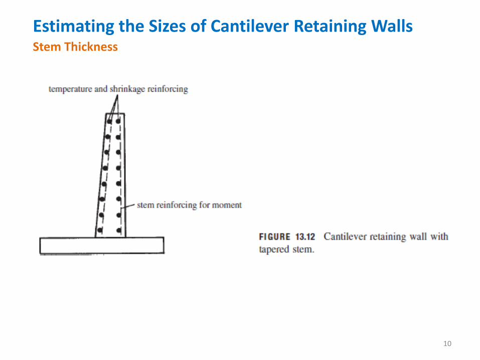
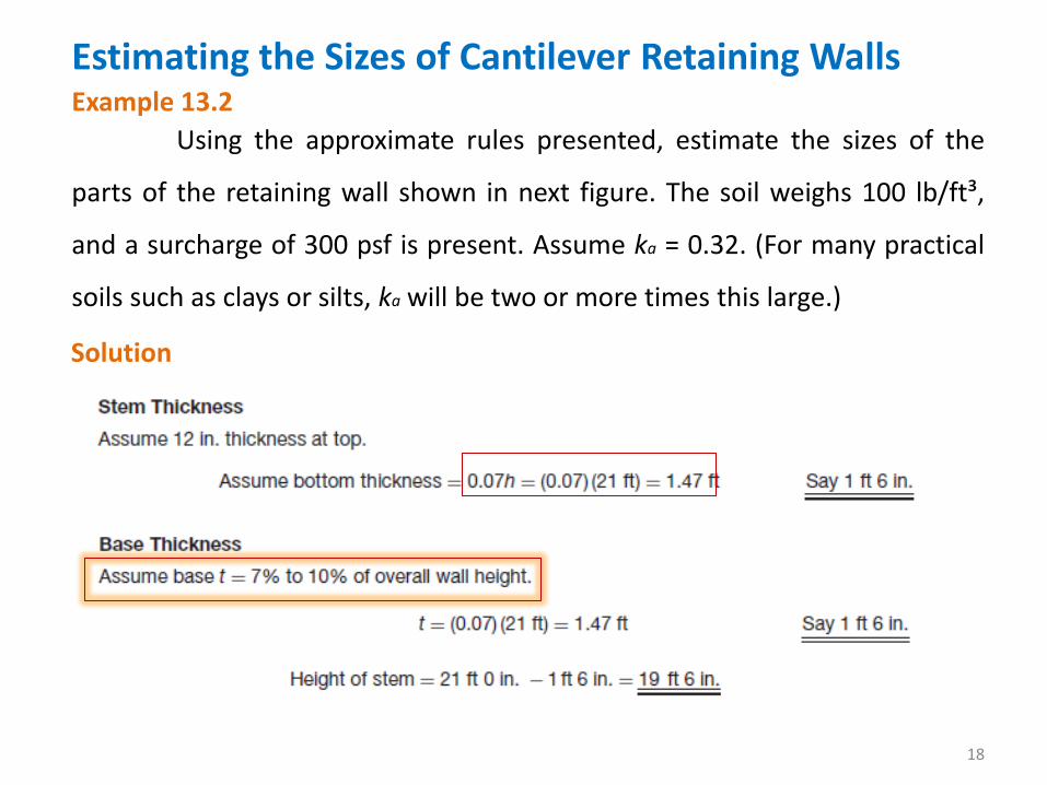
Stems are theoretically thickest at their bases because the shears
and moments are greatest there. They will ordinarily have total thicknesses
somewhere in the range of 7% to 12% of the overall heights of the retaining
walls. The shears and moments in the stem decrease from the bottom to the
top; as a result, thicknesses and reinforcement can be reduced
proportionately. Stems are normally tapered. The minimum thickness at the
top of the stem is 8 in., with 12 in. preferable. As will be shown in Section
later, it is necessary to have a mat of reinforcing in the inside face of the stem
and another mat in the outside face. To provide room for these two mats of
reinforcing, for cover and spacing between the mats, a minimum total
thickness of at least 8 in. is required.
Stem Thickness
Estimating the Sizes of Cantilever Retaining Walls
10
Stem Thickness
Estimating the Sizes of Cantilever Retaining Walls
11
The use of the minimum thickness possible for walls that are
primarily reinforced in one direction (here it’s the vertical bars) doesn’t
necessarily provide the best economy. The reason is that the reinforcing steel
is a major part of the total cost. Making the walls as thin as possible will save
some concrete but will substantially increase the amount of reinforcing
needed. For fairly high and heavily loaded walls, greater thicknesses of
concrete may be economical.
Stem Thickness
If ρ in the stem is limited to a maximum value of approximately
(0.18f’c/fy), the stem thickness required for moment will probably provide
sufficient shear resistance without using stirrups. Furthermore, it will
probably be sufficiently thick to limit lateral deflections to reasonable values.
Estimating the Sizes of Cantilever Retaining Walls
12
For heights up to about 12 ft, the stems of cantilever retaining walls
are normally made of constant thickness because the extra cost of setting
the tapered formwork is usually not offset by the savings in concrete. Above
12-ft heights, concrete savings are usually sufficiently large to make tapering
economical.
Stem Thickness
Actually, the sloping face of the wall can be either the front or the
back, but if the outside face is tapered, it will tend to counteract somewhat
the deflection and tilting of the wall because of lateral pressures. A taper or
batter of ¼ in. per foot of height is often recommended to offset deflection
or the forward tilting of the wall.
Estimating the Sizes of Cantilever Retaining Walls
13
The final thickness of the base will be determined on the basis of
shears and moments. For estimating, however, its total thickness will
probably fall somewhere between 7% and 10% of the overall wall height.
Minimum thicknesses of at least 10 in. to 12 in. are used.
Base Thickness
Estimating the Sizes of Cantilever Retaining Walls
14
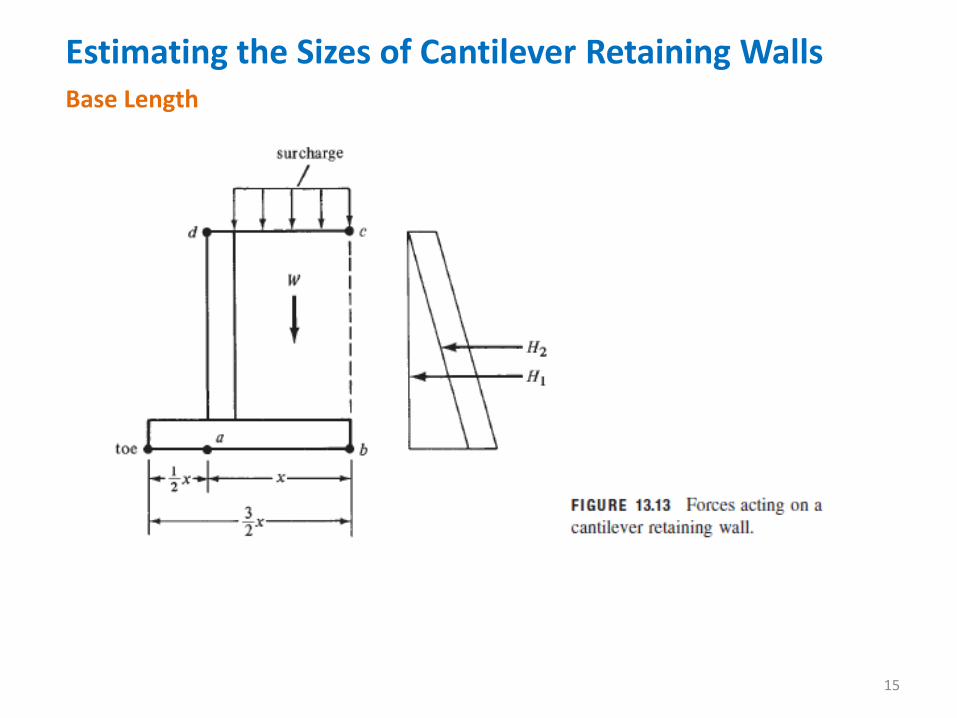
For preliminary estimates, the base length can be taken to be about
40% to 60% of the overall wall height. A little better estimate, however, can
be made by using the method described by Professor Ferguson in his
reinforced concrete text. For this discussion, reference is made to Figure
13.13. In this figure, W is assumed to equal the weight of all the material
within area abcd. This area contains both concrete and soil, but the authors
assume here that it is all soil. This means that a slightly larger safety factor
will be developed against overturning than assumed. When surcharge is
present, it will be included as an additional depth of soil, as shown in the
figure.
Base Length
Estimating the Sizes of Cantilever Retaining Walls
15
Base Length
Estimating the Sizes of Cantilever Retaining Walls
16
If the sum of moments about point a due to W and the lateral forces
H1 and H2 equal zero, the resultant force, R, will pass through point a. Such a
moment equation can be written, equated to zero, and solved for x. Should
the distance from the footing toe to point a be equal to one-half of the
distance x in the figure and the resultant force, R, pass through point a, the
footing pressure diagram will be triangular. In addition, if moments are taken
about the toe of all the loads and forces for the conditions described, the
safety factor against overturning will be approximately two.
Base Length
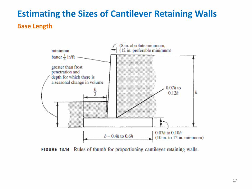
A summary of the preceding approximate first trial sizes for
cantilever retaining walls is shown in Figure 13.14. These sizes are based on
the dimensions of walls successfully constructed in the past. They often will
be on the conservative side.
Estimating the Sizes of Cantilever Retaining Walls
17
Base Length
Estimating the Sizes of Cantilever Retaining Walls
18
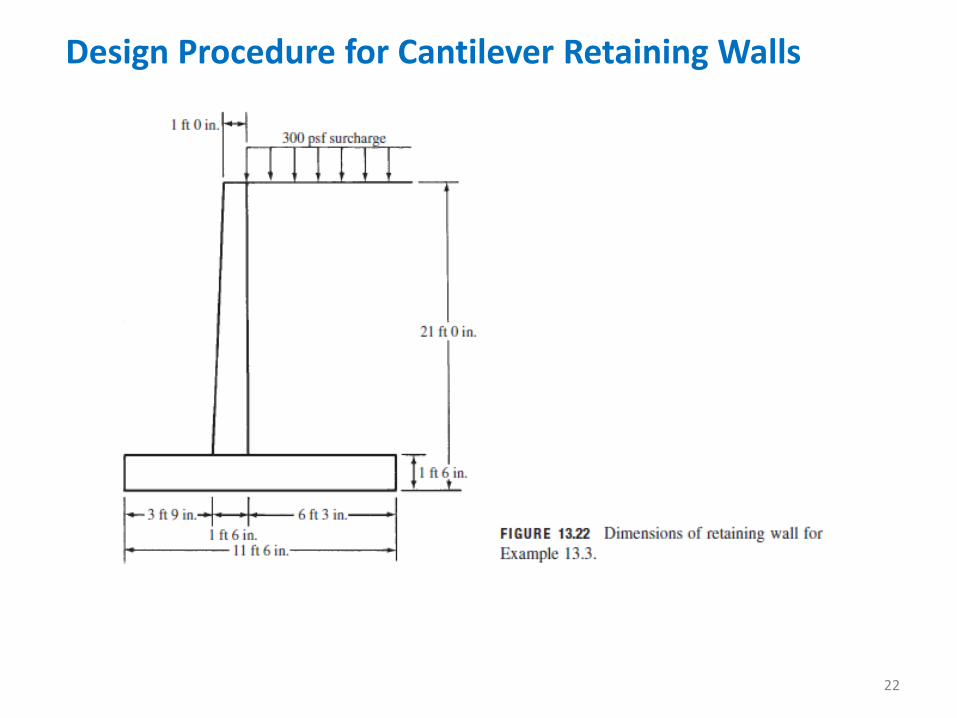
Using the approximate rules presented, estimate the sizes of the
parts of the retaining wall shown in next figure. The soil weighs 100 lb/ft³,
and a surcharge of 300 psf is present. Assume ka = 0.32. (For many practical
soils such as clays or silts, ka will be two or more times this large.)
Example 13.2
Solution
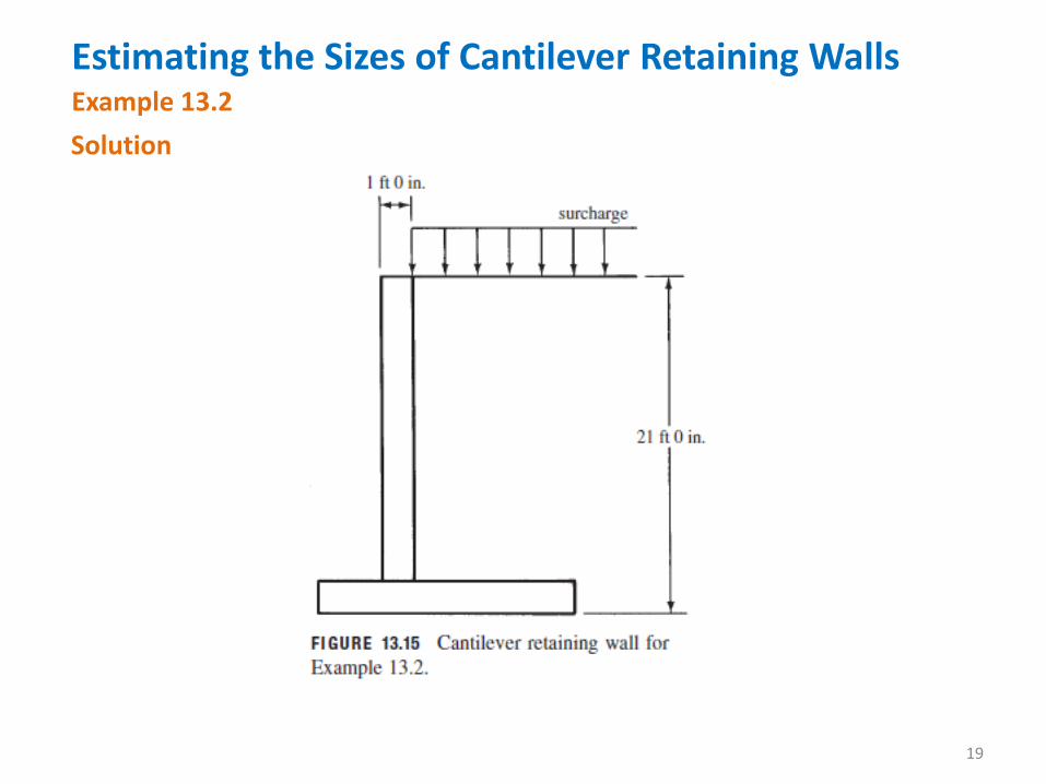
Estimating the Sizes of Cantilever Retaining Walls
19
Example 13.2
Solution
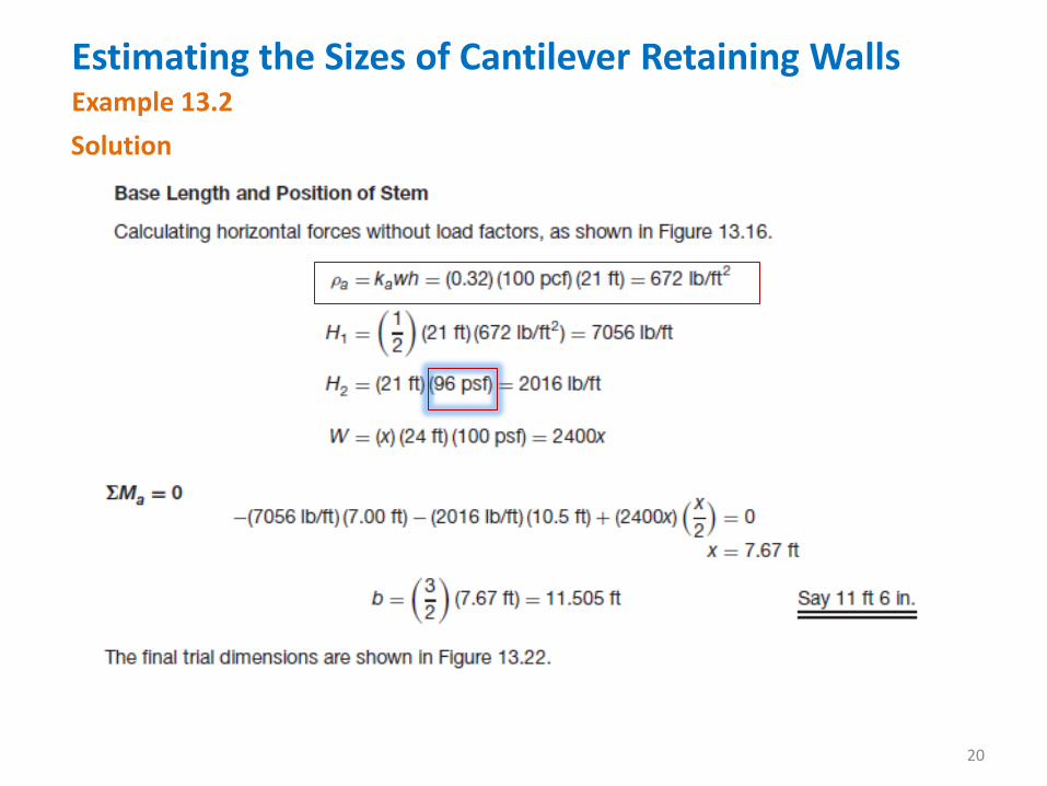
Estimating the Sizes of Cantilever Retaining Walls
20
Example 13.2
Solution
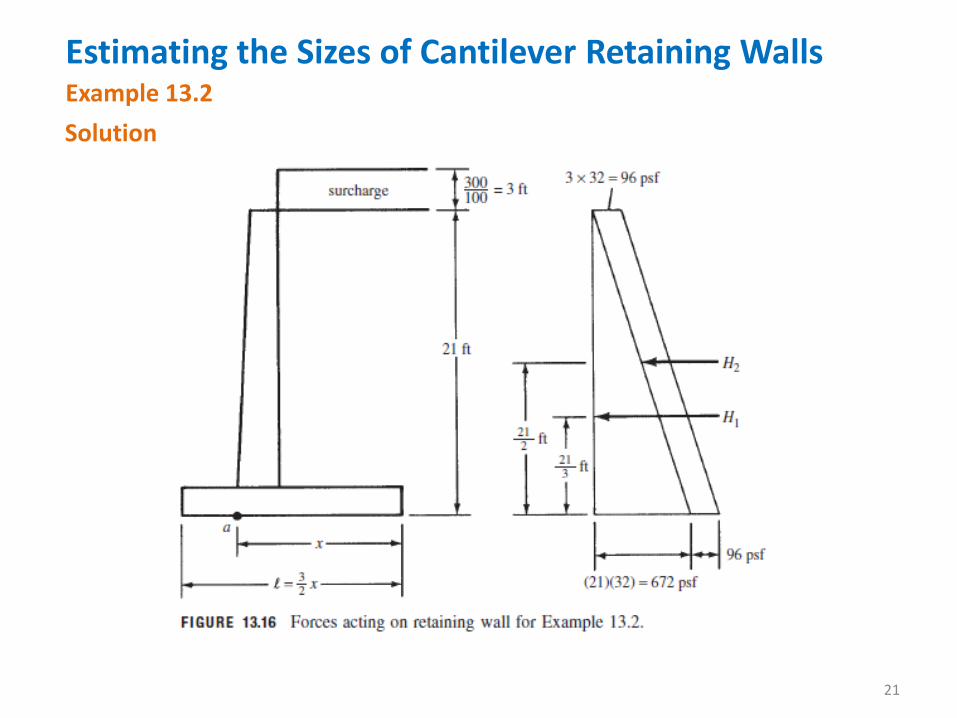
Estimating the Sizes of Cantilever Retaining Walls
21
Example 13.2
Solution
Design Procedure for Cantilever Retaining Walls
22
Design Procedure for Cantilever Retaining Walls
23
This section is provides in some detail the procedure used for
designing a cantilever retaining wall. At the end, the complete design of such
a wall is presented. Once the approximate size of the wall has been
established, the stem, toe, and heel can be designed in detail. Each of these
parts will be designed individually as a cantilever sticking out of a central
mass.
Stem
The values of shear and moment at the base of the stem resulting
from lateral earth pressures are computed and used to determine the stem
thickness and necessary reinforcing. Because the lateral pressures are
considered to be live load forces, a load factor of 1.6 is used.
Design Procedure for Cantilever Retaining Walls
24
Stem
It will be noted that the bending moment requires the use of
vertical reinforcing bars on the soil side of the stem. In addition,
temperature and shrinkage reinforcing must be provided. In Section 14.3 of
the ACI Code, a minimum value of horizontal reinforcing equal to 0.0025 of
the area of the wall, bt, is required as well as a minimum amount of vertical
reinforcing (0.0015). These values may be reduced to 0.0020 and 0.0012 if
the reinforcing is ⅝ in. or less in diameter and if it consists of bars or welded
wire fabric (not larger than W31 or D31), with fy equal to or greater than
60,000 psi.
Design Procedure for Cantilever Retaining Walls
25
Stem
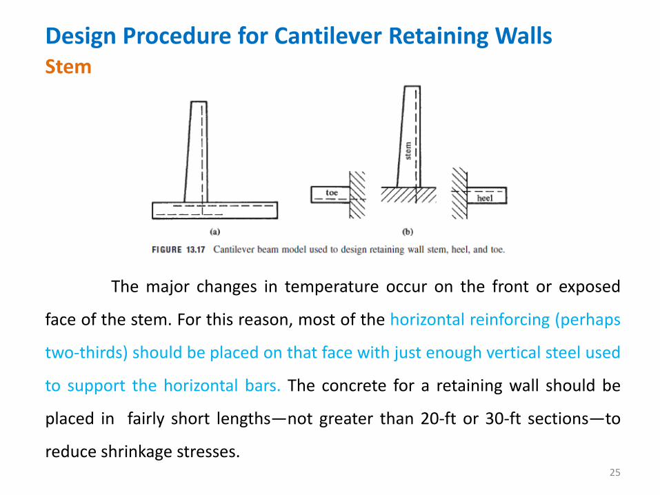
The major changes in temperature occur on the front or exposed
face of the stem. For this reason, most of the horizontal reinforcing (perhaps
two-thirds) should be placed on that face with just enough vertical steel used
to support the horizontal bars. The concrete for a retaining wall should be
placed in fairly short lengths—not greater than 20-ft or 30-ft sections—to
reduce shrinkage stresses.
Design Procedure for Cantilever Retaining Walls
26
Factor of Safety Against Sliding
Consideration of sliding for retaining walls is a most important topic
because a very large percentage of retaining wall failures occur because of
sliding. To calculate the factor of safety against sliding, the estimated sliding
resistance (equal to the coefficient of friction for concrete on soil times the
resultant vertical force, μRv) is divided by the total horizontal force. The
passive pressure against the wall is neglected, and the un-factored loads are
used.
Typical design values of μ, the coefficient of friction between the
footing concrete and the supporting soil, are as follows: 0.45 to 0.55 for
coarse-grained soils, with the lower value applying if some silt is present, and
0.6 if the footing is supported on sound rock with a rough surface. Values of
0.3 to 0.35 are used if the supporting material is silt.
Design Procedure for Cantilever Retaining Walls
27
Factor of Safety Against Sliding
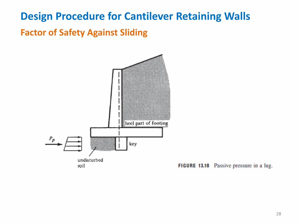
It is usually felt that the factor of safety against sliding should be at
least equal to 1.5. When retaining walls are initially designed, the calculated
factor of safety against sliding is very often considerably less than this value.
To correct the situation, the most common practice is to widen the footing on
the heel side. Another practice is to use a lug or key, as shown in Figure 13.18,
with the front face cast directly against undisturbed soil. (Many designers feel
that the construction of keys disturbs the soil so much that they are not
worthwhile.) Keys are thought to be particularly necessary for moist clayey
soils. The purpose of a key is to cause the development of passive pressure in
front of and below the base of the footing, as shown by Pp in the figure.
Design Procedure for Cantilever Retaining Walls
28
Factor of Safety Against Sliding
Design Procedure for Cantilever Retaining Walls
29
Factor of Safety Against Sliding
Many designers select the sizes of keys by rules of thumb. One
common practice is to give them a depth between two-thirds and the full
depth of the footing. They are usually made approximately square in cross
section and have no reinforcing provided other than perhaps the dowels
mentioned in the next paragraph.
Keys are often located below the stem so that some dowels or
extended vertical reinforcing may be extended into them. If this procedure is
used, the front face of the key needs to be at least 5 in. or 6 in. in front of the
back face of the stem to allow room for the dowels. From a soil mechanics
view, keys may be a little more effective if they are placed a little farther
toward the heel.
Design Procedure for Cantilever Retaining Walls
30
Factor of Safety Against Sliding
If the key can be extended down into a very firm soil or even rock,
the result will be a greatly increased sliding resistance—that resistance being
equal to the force necessary to shear the key off from the footing.
Design Procedure for Cantilever Retaining Walls
31
Heel Design Lateral earth pressure tends to cause the retaining wall to rotate
about its toe. This action tends to pick up the heel into the backfill. The
backfill pushes down on the heel cantilever, causing tension in its top. The
major force applied to the heel of a retaining wall is the downward weight of
the backfill behind the wall. Although it is true that there is some upward soil
pressure, many designers choose to neglect it because it is relatively small.
The downward loads tend to push the heel of the footing down, and the
necessary upward reaction to hold it attached to the stem is provided by the
vertical tensile steel in the stem, which is extended down into the footing.
Design Procedure for Cantilever Retaining Walls
32
Heel Design
Because the reaction in the direction of the shear does not introduce
compression into the heel part of the footing in the region of the stem, it is
not permissible to determine Vu at a distance d from the face of the stem, as
provided in Section 11.1.3.1 of the ACI Code. The value of Vu is determined
instead at the face of the stem because of the downward loads. This shear is
often of such magnitude as to control the thickness, but the moment at the
face of the stem should be checked also. Because the load here consists of
soil and concrete, a load factor of 1.2 is used for making the calculations.
It will be noted that the bars in the heel will be in the top of the
footing. As a result, the required development length of these “top bars” may
be rather large.
Design Procedure for Cantilever Retaining Walls
33
Heel Design
The percentage of flexural steel required for the heel frequently is
less than the ρmin of 200/fy and Despite the fact that the ACI Code
(10.5.4) exempts slabs of uniform from these ρmin values, it is recommended
that these be used because the retaining wall is a major beam like structure.
Design Procedure for Cantilever Retaining Walls
34
Toe Design
The toe is assumed to be a beam cantilevered from the front face of
the stem. The loads it must support include the weight of the cantilever slab
and the upward soil pressure beneath. Usually any earth fill on top of the toe
is neglected (as though it has been eroded). Obviously, such a fill would
increase the upward soil pressure beneath the footing, but because it acts
downward and cancels out the upward pressure, it produces no appreciable
changes in the shears and moments in the toe.
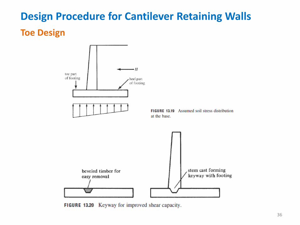
A study of Figure 13.19 shows that the upward soil pressure is the
major force applied to the toe. Because this pressure is primarily caused by
the lateral force H, a load factor of 1.6 is used for the calculations.
Design Procedure for Cantilever Retaining Walls
35
Toe Design
The maximum moment for design is taken at the face of the stem,
whereas the maximum shear for design is assumed to occur at a distance d
from the face of the stem because the reaction in the direction of the shear
does introduce compression into the toe of the footing. The average designer
makes the thickness of the toe the same as the thickness of the heel,
although such a practice is not essential.
Design Procedure for Cantilever Retaining Walls
36
Toe Design
Design Procedure for Cantilever Retaining Walls
37
Toe Design
It is a common practice in retaining wall construction to provide a
shear keyway between the base of the stem and the footing. This practice,
though definitely not detrimental, is of questionable value. The keyway is
normally formed by pushing a beveled 2 in. × 4 in. or 2 in. × 6 in. into the top
of the footing, as shown in Figure 13.20. After the concrete hardens, the
wood member is removed, and when the stem is cast in place above, a
keyway is formed. It is becoming more and more common simply to use a
roughened surface on the top of the footing where the stem will be placed.
This practice seems to be just as satisfactory as the use of a keyway.
Design Procedure for Cantilever Retaining Walls
38
Toe Design In next example, #8 bars 6 in. on center are selected for the vertical
steel at the base of the stem. These bars need to be embedded into the
footing for development purposes, or dowels equal to the stem steel need to
be used for the transfer. This latter practice is quite common because it is
rather difficult to hold the stem steel in position while the base concrete is
placed.
The required development length of the #8 bars down into the
footing or for #8 dowels is 33 in. when fy = 60,000 psi and f’c = 3000 psi. This
length cannot be obtained vertically in the 1-ft-6-in. footing used unless the
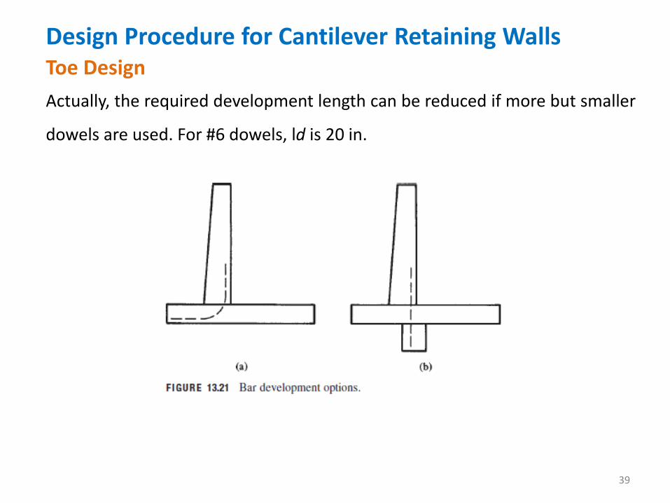
bars or dowels are either bent as shown in Figure 13.21(a) or extended
through the footing and into the base key as shown in Figure 13.21(b).
Design Procedure for Cantilever Retaining Walls
39
Toe Design
Actually, the required development length can be reduced if more but smaller
dowels are used. For #6 dowels, ld is 20 in.
Design Procedure for Cantilever Retaining Walls
40
Toe Design
If instead of dowels the vertical stem bars are embedded into the
footing, they should not extend up into the wall more than 8 ft or 10 ft before
they are spliced because they are difficult to handle in construction and may
easily be bent out of place or even broken. Actually, after examining Figure
13.21(a), you can see that such an arrangement of stem steel can sometimes
be very advantageous economically.
The bending moment in the stem decreases rapidly above the base;
as a result, the amount of reinforcing can be similarly reduced. It is to be
remembered that these bars can be cut off only in accordance with the ACI
Code development length requirements.
Design Procedure for Cantilever Retaining Walls
41
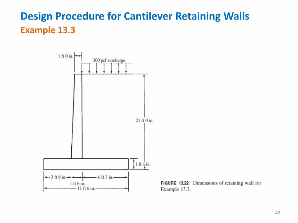
Example 13.3
Complete the design of the cantilever retaining wall whose
dimensions were estimated in Example 13.2, if f’c = 3000 psi, fy = 60,000 psi,
qa = 4000 psf, and the coefficient of sliding friction equals 0.50 for concrete
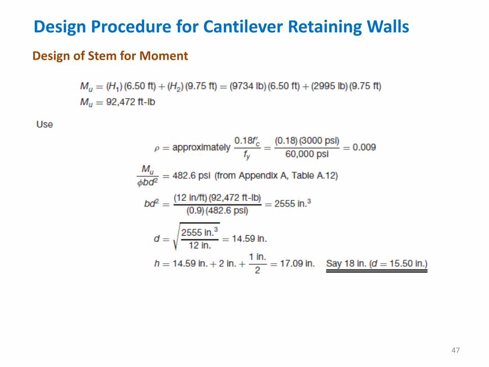
on soil. Use ρ approximately equal to 0.18f’c/fy to maintain reasonable
deflection control.
Solution
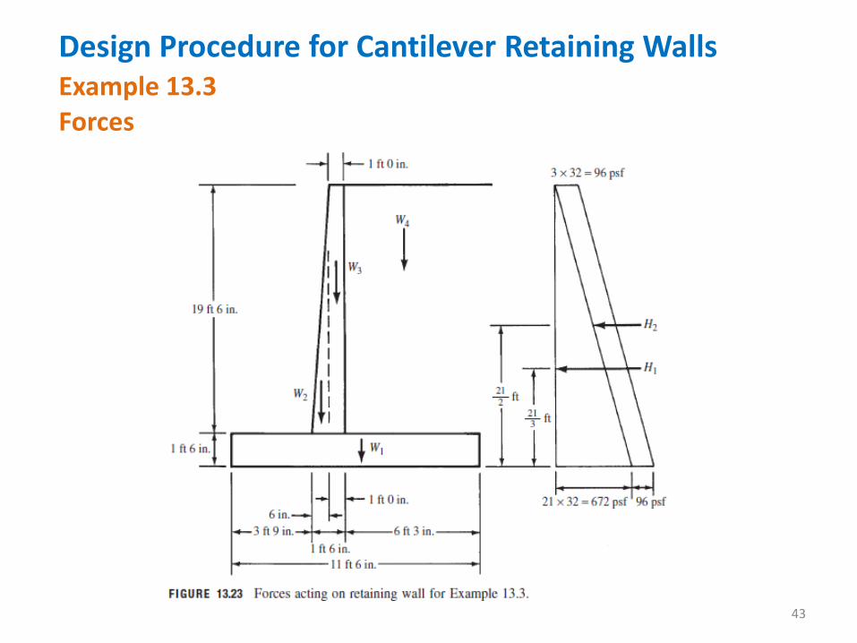
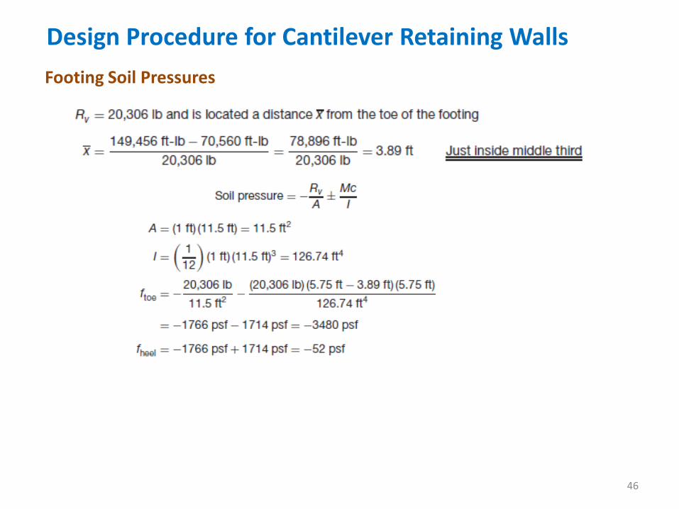
The safety factors against overturning and sliding and the soil pressures under
the heel and toe are computed using the actual un-factored loads.
Design Procedure for Cantilever Retaining Walls
42
Example 13.3
Design Procedure for Cantilever Retaining Walls
43
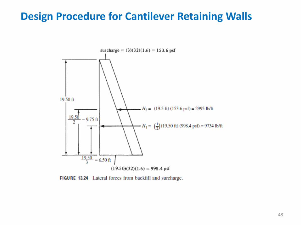
Example 13.3 Forces
Design Procedure for Cantilever Retaining Walls
44
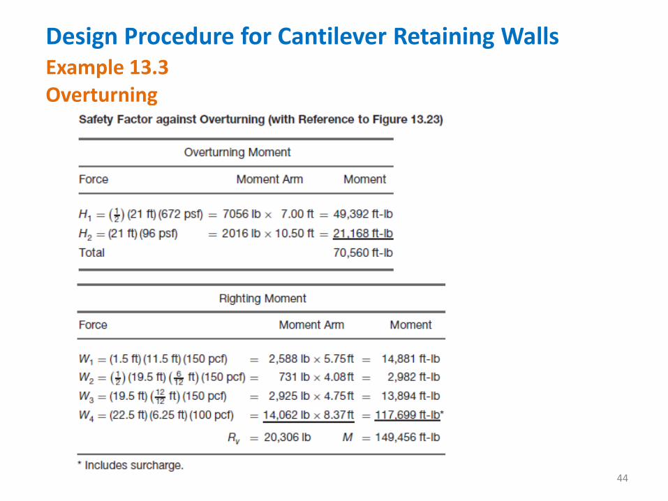
Example 13.3 Overturning
Design Procedure for Cantilever Retaining Walls
45
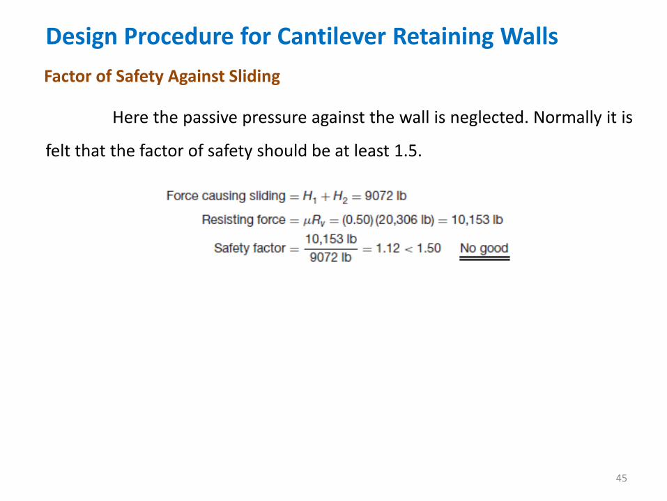
Factor of Safety Against Sliding
Here the passive pressure against the wall is neglected. Normally it is
felt that the factor of safety should be at least 1.5.
Design Procedure for Cantilever Retaining Walls
46
Footing Soil Pressures
Design Procedure for Cantilever Retaining Walls
47
Design of Stem for Moment
Design Procedure for Cantilever Retaining Walls
48
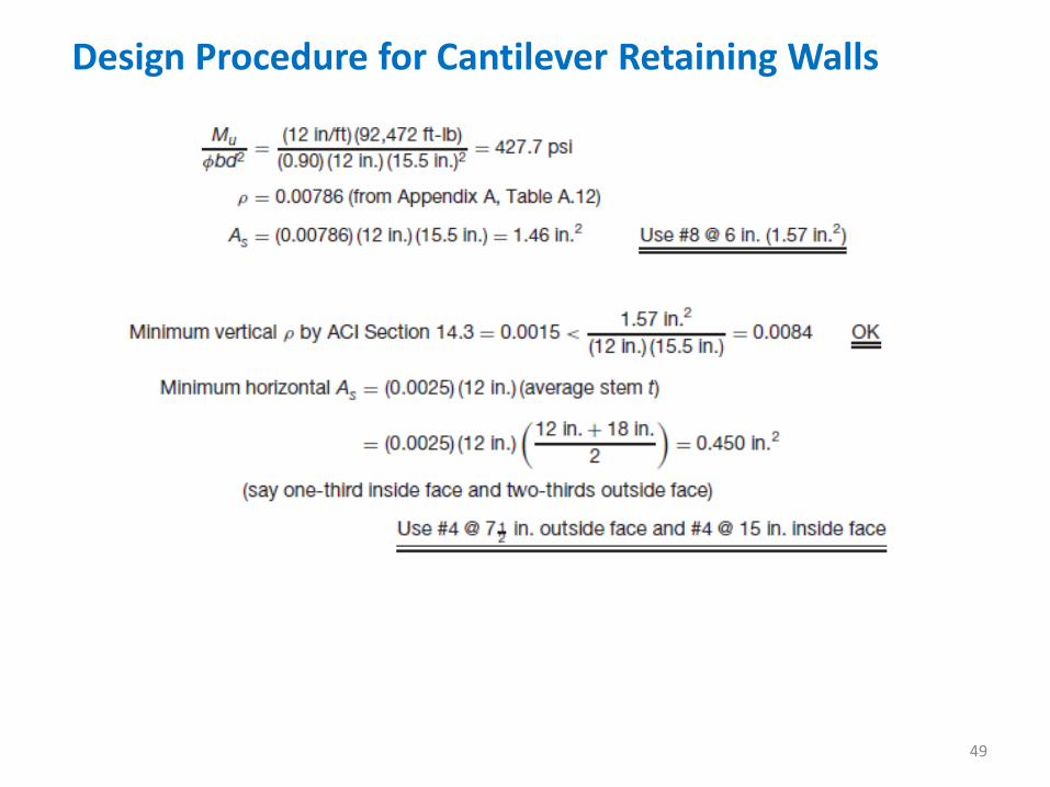
Design Procedure for Cantilever Retaining Walls
49
Design Procedure for Cantilever Retaining Walls
50
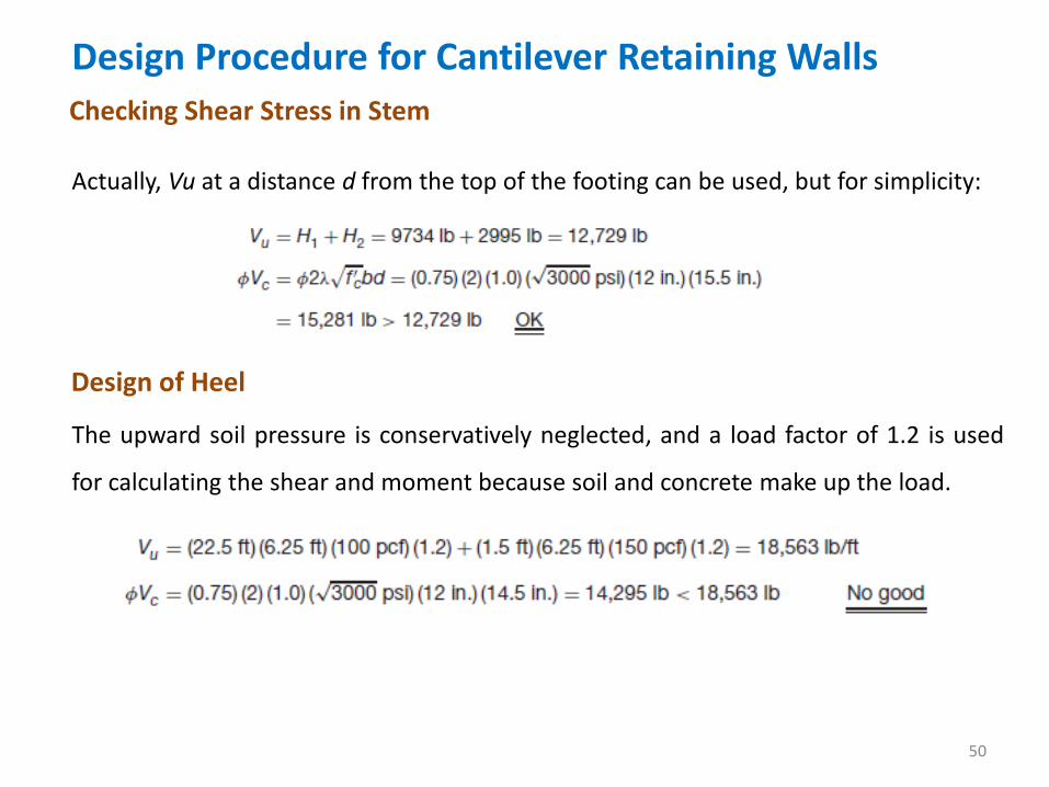
Checking Shear Stress in Stem
Actually, Vu at a distance d from the top of the footing can be used, but for simplicity:
Design of Heel
The upward soil pressure is conservatively neglected, and a load factor of 1.2 is used
for calculating the shear and moment because soil and concrete make up the load.
Design Procedure for Cantilever Retaining Walls
51
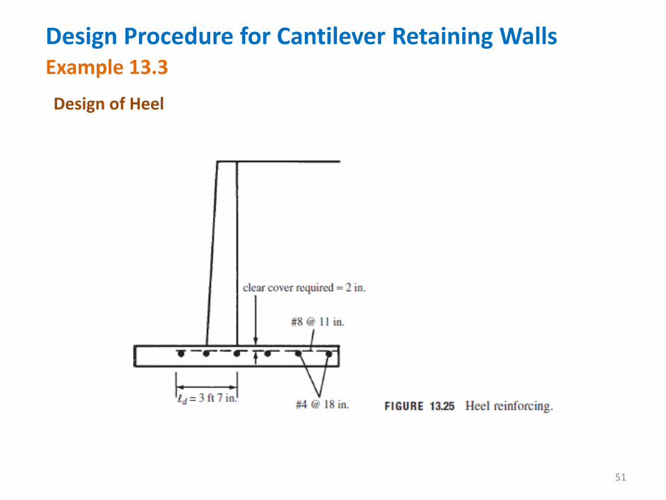
Example 13.3
Design of Heel
Design Procedure for Cantilever Retaining Walls
52
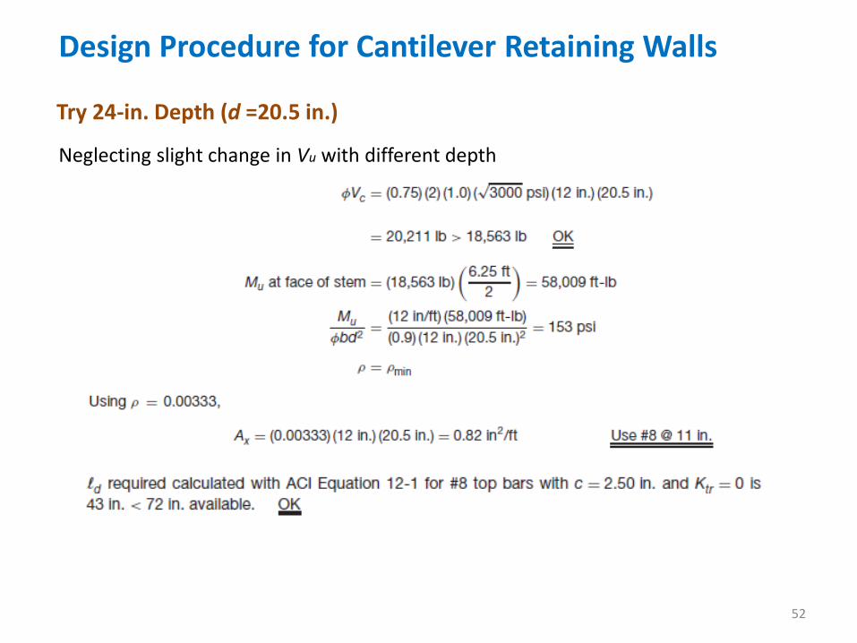
Try 24-in. Depth (d =20.5 in.)
Neglecting slight change in Vu with different depth
Design Procedure for Cantilever Retaining Walls
53
Try 24-in. Depth (d =20.5 in.)
Heel reinforcing is shown in Figure 13.25.
Note: Temperature and shrinkage steel is normally considered unnecessary in the heel and toe.
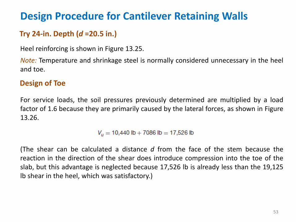
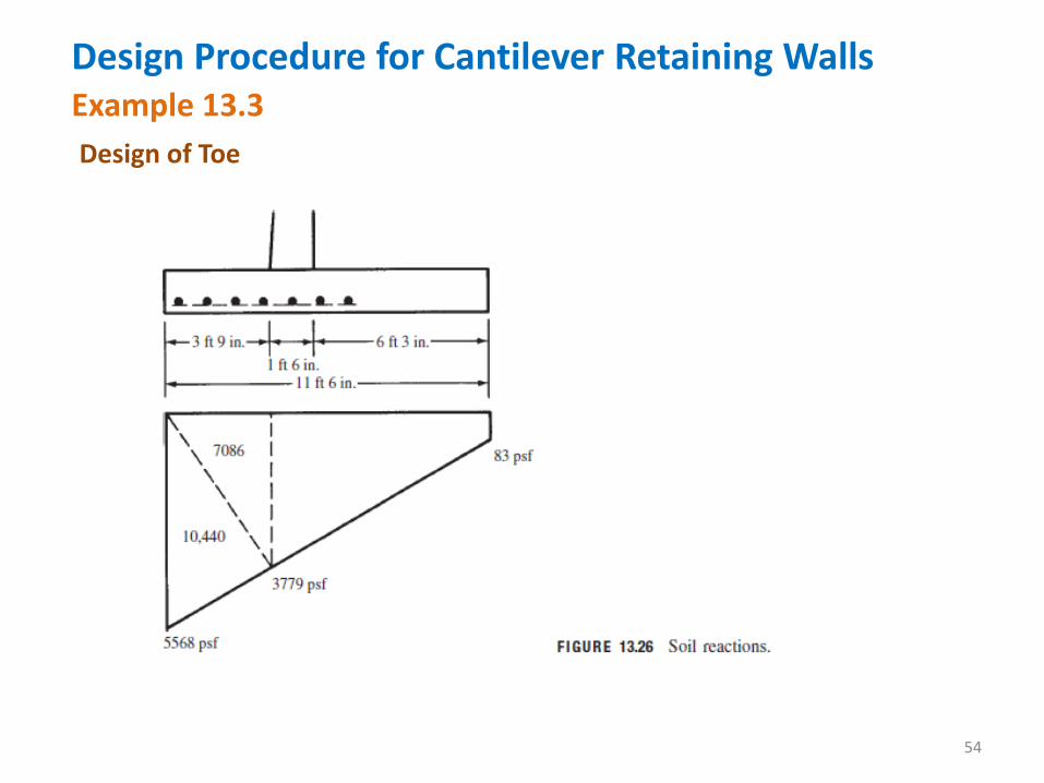
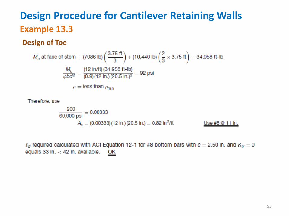
Design of Toe
For service loads, the soil pressures previously determined are multiplied by a load factor of 1.6 because they are primarily caused by the lateral forces, as shown in Figure 13.26.
(The shear can be calculated a distance d from the face of the stem because the reaction in the direction of the shear does introduce compression into the toe of the slab, but this advantage is neglected because 17,526 lb is already less than the 19,125 lb shear in the heel, which was satisfactory.)
Design Procedure for Cantilever Retaining Walls
54
Example 13.3
Design of Toe
Design Procedure for Cantilever Retaining Walls
55
Example 13.3
Design of Toe
Design Procedure for Cantilever Retaining Walls
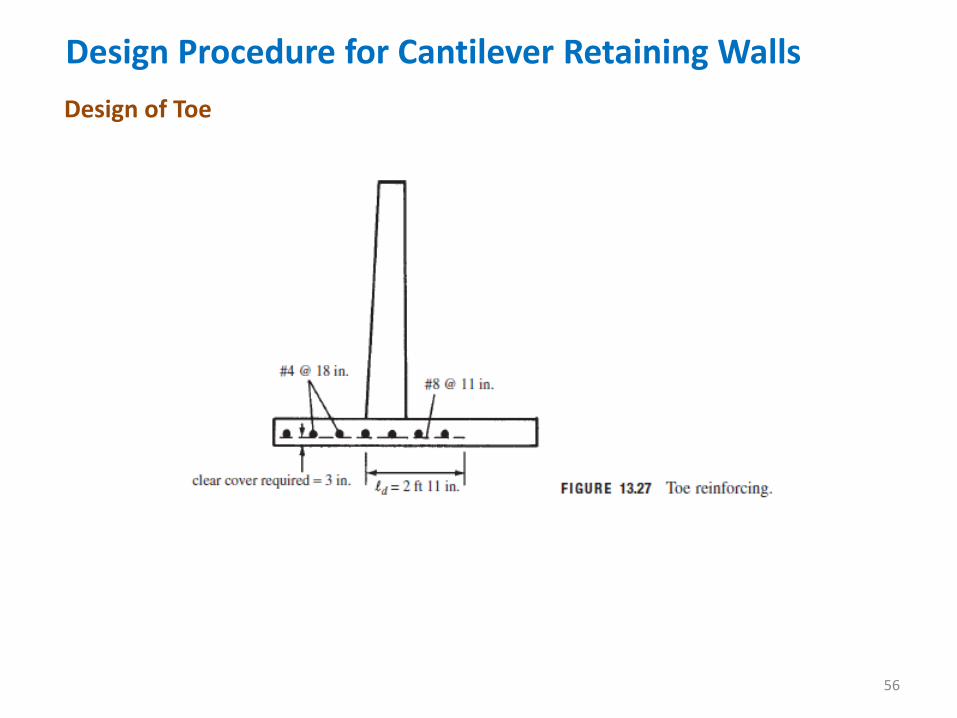
56
Design of Toe
Design Procedure for Cantilever Retaining Walls
57
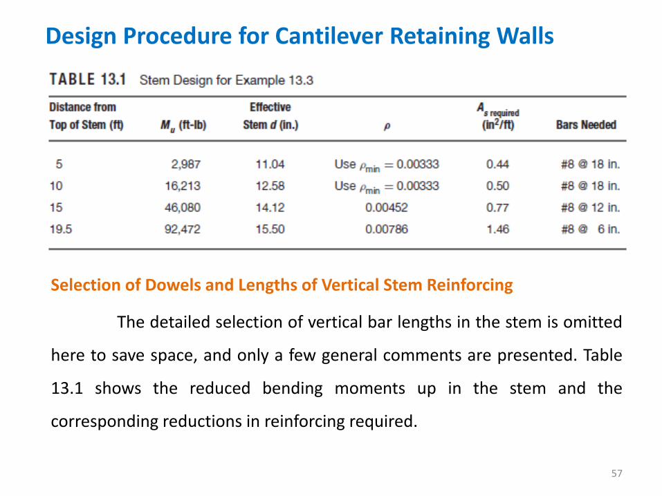
Selection of Dowels and Lengths of Vertical Stem Reinforcing
The detailed selection of vertical bar lengths in the stem is omitted
here to save space, and only a few general comments are presented. Table
13.1 shows the reduced bending moments up in the stem and the
corresponding reductions in reinforcing required.

Design Procedure for Cantilever Retaining Walls
58
Selection of Dowels and Lengths of Vertical Stem Reinforcing
After considering the possible arrangements of the steel in Figure
13.21 and the required areas of steel at different elevations in Table 13.1,
the authors decided to use dowels for load transfer at the stem base.
Use #8 dowels at 6 in. extending 33 in. down into footing and key.
If these dowels are spliced to the vertical stem reinforcing with no
more than one half the bars being spliced within the required lap length, the
splices will fall into the class B category (ACI Code 12.15), and their lap
length should at least equal 1.3ld = (1.3) (33) = 43 in. Therefore, two dowel
lengths are used—half 3 ft 7 in. up into the stem and the other half 7 ft 2
in.—and the #7 bars are lapped over them, half running to the top of the
wall and the other half to mid-depth.
Design Procedure for Cantilever Retaining Walls
59
Selection of Dowels and Lengths of Vertical Stem Reinforcing
Actually, a much more refined design can be made that involves more
cutting of bars. For such a design, a diagram comparing the theoretical steel
area required at various elevations in the stem and the actual steel
furnished is very useful. It is to be remembered (ACI Code 12.10.3) that the
bars cut off must run at least a distance d or 12 diameters beyond their
theoretical cutoff points and must also meet the necessary development
length requirements.