RW03 - Building Inspections Brisbane...
31
RW03 Concrete Masonry - Gravity Retaining Walls
-
Upload
vuongtuyen -
Category
Documents
-
view
221 -
download
0
Transcript of RW03 - Building Inspections Brisbane...
RW03 Concrete Masonry - Gravity Retaining Walls

Intern
Textbox
While the contents of this publication are believed to be accurate and complete, the information given is intended for general guidance and does not replace the services of professional advisers on specific projects. Concrete Masonry Association of Australia cannot accept any liability whatsoever regarding the contents of this publication. Copyright © Concrete Masonry Association of Australia 2014. ABN 33 065 618 804. This publication, its contents and format are copyright of the Concrete Masonry Association of Australia, and may not be reproduced, copied or stored in any medium without prior, written authorisation from the Institute. Concrete Masonry Association of Australia is wholly sponsored by the Australian concrete brick, block and paver industry. Local or state regulations may require variation from the practices and recommendations contained in this publication. First published November 2003. The Standards referenced in this manual were current at the time of publication. Manufacture: Adbri Masonry
Intern
Textbox
Intern
Textbox
PO Box 370, Artarmon NSW 1570 Australia Suite 3.02, Level 3, 44 Hampden Road Artarmon NSW 2064 Australia Telephone +61 2 8448 5500 Fax +61 2 9411 3801 ABN 30003873309 www.cmaa.com.au

Concrete Masonry – Gravity Retaining Walls
Concrete Masonry Association of Australia
Reposted with alternative approach using Rankine–Bell Method and cohesion to calculate horizontal forces in worked example, plus amendments to Construction Specification and addition of Appendix D and Appendix E, March 2005
Reposted with additional explanations throughout, on Passive Pressure, Cohesion, Vertical Friction of Wall and Base Sliding, April 2004
First posted on the web, November 2003
© 2005 Concrete Masonry Association of Australia.
Except where the Copyright Act allows otherwise, no part of this publication may be reproduced, stored in a retrieval system in any form or transmitted by any means without prior permission in writing of the Concrete Masonry Association of Australia.
The information provided in this publication is intended for general guidance only and in no way replaces the services of professional consultants on particular projects. No liability can therefore be accepted by the Concrete Masonry Association of Australia for its use.
It is the responsibility of the user of this Guide to check the Concrete Masonry Association of Australia web site (www.cmaa.com.au) for the latest amendments and revisions.
ISBN 0 909407 52 5
Segmental ConcreteGravity Retaining Walls
2
ABN 33 065 618 840
PO Box 370 Artarmon NSW 2064
T: 02 8448 5500 F: 02 9411 3801
E: [email protected] W: www.cmaa.com.au
The following organisations are recognised for their support and financial contribution towards this publication.
Bayer Chemicals Pty Ltd www.bayerchemicals.com
Cement and Concrete Association of Australia www.concrete.net.au
Colombia Concrete Block Machine Pty Ltd www.colmac.com
MANUFACTURERS:
Baines Masonary Blocks www.bainesmasonary.com.au
Best Masonry Bricks and Pavers Pty Ltd www.bestbrickspavers.com.au
Boral Masonry Pty Ltd www.boral.com.au
C&M Brick Pty Ltd www.cmbrick.com.au
Erosion Control Systems Pty Ltd www.erosioncontrol.com.au
GB Masonry Pty Ltd www.gbmasonry.com.au
Gympie Blockworks www.gympieblockworks.com.au
Island Block and Paving Pty Ltd www.islandblock-paving.com.au
Master Masonry www.mastermasonry.com.au
Modular Masonry (WA) Pty Ltd www.modularmasonry.com.au
Nubrik Pty Ltd www.nubrik.com.au
Pioneer Building Products www.pioneerbuildingproducts.com.au
LICENSORS:
Allan Block Corporation www.allanblock.com
Anchor Retaining Wall Systems www.anchorwall.com
Norfolk and Tasman Retaining Walls www.islandblock-paving.com.au
Keystone Retaining Wall Systems www.keystonewalls.com
Rockwood Retaining Walls, Inc www.rockwoodretainingwalls.com
Preface
Standards Australia has published AS 4678–2002 for the design of earth retaining structures, which include segmental concrete gravity retaining walls. It encompasses the following features:■ Limit state design■ Partial loading and material factors ■ Compatibility with the general approach in
AS 1170 SAA Loading code(Note1)
■ Compatibility with the structures standards such as AS 3600 Concrete structures and AS 3700 Masonry structures.
This Guide provides Australian designers and contractors with a comprehensive approach to the design and construction of segmental concrete gravity retaining walls based on:■ The design and construction rules set out in
AS 4678-2002■ An analysis method developed by the Concrete
Masonry Association of Australia (CMAA) to fit Australian experience.
It includes:■ A description of the principal features of the
Australian Standard■ A description of the analysis method■ A design example which demonstrates the use of
the Australian Standard and analysis method■ A site investigation check list■ A detailed construction specification.
NOTES: 1 When published in early 2002, AS 4678 included load factors which were compatible with the load factors on the version of AS 1170 that was then current. However, changes to AS 1170 in late 2002 have meant that exact similarity of load factors no longer exists.
INSTRUCTIONSYou may click on anything shown in RED to go to it.

Segmental ConcreteGravity Retaining Walls
3
Contents
1 Introduction 4 1.1 General 4
1.2 Scope 4
1.3 Glossary 4
1.4 Behaviour of Segmental Concrete Gravity Retaining Walls 5
1.5 Importance of a Geotechnical Report 6
1.6 Safety and Protection of Existing Structures 6
1.7 Global Slip Failure 6
1.8 Differential Settlement 7
1.9 Importance of Drainage 7
1.10 Passive Pressure 7
2 Design Considerations 8 2.1 Scope 8
2.2 Limit State Design 8
2.3 Partial Loading and Material Factors 8
2.4 Load Combinations and Factors for Stability 8
2.5 Load Combinations and Factors for Strength of Components 9
2.6 Live Loads 9
2.7 Earthquake Loads 10
2.8 Wind Loads 10
2.9 Hydraulic Loads 10
2.10 Drained Vs Undrained Parameters 10
2.11 Capacity Reduction Factors 10
2.12 Soil Analysis Model 10
2.13 Active Pressure 11
2.14 Pressure at Rest 11
2.15 Passive Pressure 11
2.16 Bearing Failure 12
2.17 Sliding Failure 12
2.18 Overturning 13
2.19 Global slip 13
2.20 Foundation Material 13
2.21 Lean Back 13
3 Appendices 13 Appendix A – Design Example 14
Appendix B – Site Investigation 21
Appendix C – Construction Specification 23
Appendix D – Height Table for Walls 800 to 1200 mm High 26
Appendix E – Details for Walls up to 800-mm High 28
INSTRUCTIONSYou may click on anything shown in RED to go to it.
ContentsSegmental ConcreteGravity Retaining Walls
4
1 Introduction
1.1 General1.1 General
For many years reinforced masonry cantilever retaining walls, relying on gravity loads to resist the overturning forces due to soil pressure, have been constructed with reinforced concrete masonry stems (steel reinforcement grouted into hollow concrete blockwork) which is built on a reinforced concrete footing.
Segmental concrete gravity retaining walls, consisting of concrete masonry units dry-stacked against a soil slope and resisting overturning by virtue of their own weight became more widespread in the 1980’s and early 1990’s. This system provided very attractive embankment finishes, but is limited in height.
A further development during the 1990’s has been the incorporation of geogrids into the soil mass behind the structure to create dry-stacked masonry reinforced soil structures. Provided the system is correctly designed and there is access to the soil mass at all levels, such a system can be constructed several metres high.
This Guide covers the design of segmental concrete gravity retaining walls. The other two forms of construction are covered in separate Guides.
In 1990 the Concrete Masonry Association of Australia (CMAA) published Masonry Walling Guide No 4 Design For Earth Loads - Retaining Walls, which set out a design methodology for earth retaining structures. It included:■ Ultimate load design with material factors based
on characteristic soil properties, partial load factors consistent with AS 1170.1 and structure designs to AS 3700 and AS 3600.
■ Coloumb analysis of the back fill■ Bearing analysis using the Meyerhoff approach
(including tilt and inclined load factors).■ Sliding analyses that account for friction, passive
pressure and (if appropriate) base adhesion.
These design and analysis features were a considerable improvement on the working stress/assumed bearing capacity/Rankine analysis that was then in common use. These principles have been adopted in Standards Australia AS 4678–2002, which is appropriate for the design of these structures.
1.2 ScopeThis manual makes use of the following design and analysis methods.■ Coulomb Method for all walls over 1200 mm high;■ Rankine-Bell Method for walls, in some situations,
in the range 800 mm to 1200 mm high;■ Simple depth to height proportions for walls, in
some situations, under 800 mm high.
1.3 GlossaryLoads and limit states:Design life The time over which the structure is required to fulfil its function and remain serviceable.
Dead load(Note 2) The self-weight of the structure and the retained soil or rock.
Live load(Note 2) Loads that arise from the intended use of the structure, including distributed, concentrated, impact and inertia loads. It includes construction loads, but excludes wind and earthquake loads.
Wind load The force exerted on the structure by wind, acting on either or both the face of the retaining wall and any other structure supported by the retaining wall.
Earthquake load The force exerted on the structure by earthquake action, acting on either or both the face of the retaining wall and any other structure supported by the retaining wall.
Stability limit state A limit state of loss of static equilibrium of a structure or part thereof, when considered as a rigid body.
Strength limit state A limit state of collapse or loss of structural integrity of the components of the retaining wall.
Serviceability limit state A limit state for acceptable in-service conditions. The most common serviceability states are excessive differential settlement and forward movement of the retaining wall.
Components:Concrete masonry units Concrete blocks manufactured to provide an attractive, durable, stable face to a retaining wall. They are available in a variety of shapes and sizes, with varying degrees of interlock.
Geotextile A permeable, polymeric material, which may be woven, non-woven or knitted. It is commonly used to separate drainage material from other soil.
Retained material The natural soil or rock, intended to be retained by a retaining wall.
Foundation material The natural soil or rock material under a retaining wall.
Infill material The soil material placed immediately behind the retaining wall facing.
Drainage material The crushed rock, gravel or similar material placed behind a retaining wall to convey ground water away from the wall and foundations. It is commonly used in conjunction with other drainage media, such as agricultural pipes.NOTES:
2 This Guide uses the terminology “dead load” to indicate permanent loads and “live load” to indicate imposed loads. This terminology is consistent with the convention adopted in AS 4678-2002.
Contents
Soil types:Cohesive fill Naturally-occurring or processed materials with greater than 50% passing the 75 µm Australian standard sieve, a Plasticity Index of less than 30% and a Liquid Limit of less than 45%.
Controlled fill Class I Soil, rock or other inert material that has been placed at a site in a controlled fashion and under appropriate supervision to ensure the resultant material is consistent in character, placed and compacted to an average density equivalent to 98% (and no test result below 95%) of the maximum dry density (standard compactive effort) for the material when tested in accordance with AS 1289.5.1.1. For cohesionless soils, material compacted to at least 75% Density Index is satisfactory.
Controlled fill Class II Soil, rock or other inert material that has been placed in specified layers and in a controlled fashion to ensure the resultant material is consistent in character, placed and compacted to an average density equivalent to 95% (and no test result below 92%) of the maximum dry density (standard compactive effort) for the material when tested in accordance with AS 1289.5.1.1. For cohesionless soils, material compacted to at least 75% Density Index is satisfactory. Generally the layer thickness is specified as a maximum of 300 mm.
Uncontrolled fill Soil, rock or other inert material that has been placed at a site and does not satisfy the materials included above.
Insitu material Natural soil, weathered rock and rock materials.
GW Well-graded gravel as defined by the Cassegrande extended classification system. Generally in the range of 2 mm to 60 mm, and graded such that the smaller particles pack into the spaces between the larger ones, giving a dense mass of interlocking particles with a high shear strength and low compressibility.
SW Well-graded sand as defined by the Cassegrande extended classification system. Generally in the range of 0.06 mm to 2 mm, and graded such that the smaller particles pack into the spaces between the larger ones, giving a dense mass of interlocking particles with a high shear strength and low compressibility.
GP Poorly-graded gravel as defined by the Cassegrande extended classification system. Generally in the range of 2 mm to 60 mm, and of a single size. This material has good drainage properties provided it is protected from infiltration by silts and clays.
No-fines concrete Concrete with a crushed rock aggregate of nominal size 12 to 20 mm, a characteristic compresive strength greater than 10 MPa and a density between 1600 and 1800 kg/m3.
1.4 Behaviour of Segmental Concrete Gravity Retaining WallsIf unrestrained, a soil embankment will slump to its angle of repose. Some soils, such as clays, have cohesion that enables vertical and near-vertical faces to remain partially intact, but even these may slump under the softening influence of ground water. When an earth-retaining structure is constructed, it restricts this slumping. The soil exerts an active pressure on the structure, which deflects a little and is then restrained by the friction and adhesion between the base and soil beneath, passive soil pressures in front of the structure and the bearing capacity of the soil beneath the toe of the structure.
If water is trapped behind the retaining structure, it exerts an additional hydraulic pressure. This ground water also reduces the adhesion and bearing resistance. If massive rock formations are present, immediately behind the structure, these will restrict the volume of soil which can be mobilised and thus reduce the pressure.
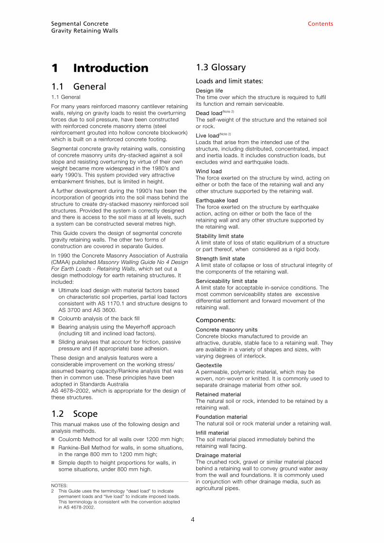
The walls described in this Guide are gravity, earth-retaining structures, consisting of dry-stacked segmental concrete units. The retained soil exerts an active pressure on the wall. Overturning is resisted by the vertical load of the structure.
Segmental ConcreteGravity Retaining Walls
5
Slotted PVC ag. pipe draining tostormwater at minimum 1 in 100 fall
Drainage material(In some cases,no-fines concretemay be used toincrease wallstability)
Infill material asper specification,if required
Excavation line
Compacted foundation
Bearing pad
Minimum fall1 in 100
Compacted clay or similarto seal surface. 150 mmminimum thickness
Drain (minimum 1 in 100 fall)to permanent stormwater system
Geotextile filtermaterial, if required
Optional capping unit
NOTE:Facing may be vertical,stepped or sloped,depending on theparticular units used
Concretesegmental units
Figure 1.1 Typical Segmental Concrete Gravity Retaining Wall
Contents
1.5 Importance of a Geotechnical ReportThe design of a retaining wall includes two essential parts:■ Analysis of the adjacent ground for global
slip, settlement, drainage and similar global considerations; and
■ Analysis and design of retaining wall structure for strength.
These analyses must be based on an accurate and complete knowledge of the soil properties, slope stability, potential slip problems and groundwater. A geotechnical report by a qualified and experienced geotechnical engineer should be obtained.
Such a report must address the following considerations, as well as any other pertinent points not listed.■ Soil properties;■ Extent and quality of any rock, including floaters
and bedrock;■ Global slip and other stability problems;■ Bedding plane slope, particularly if they slope
towards the cut;■ Effect of prolonged wet weather and the
consequence of the excavation remaining open for extended periods;
■ Effect of ground water;■ Steep back slopes and the effect of terracing; ■ Effect of any structures founded within a zone of
influence.
1.6 Safety and Protection of Existing StructuresWhenever soil is excavated or embankments are constructed, there is a danger of collapse. This may occur through movement of the soil and any associated structures by:■ rotation around an external failure plane that
encompasses the structure,■ slipping down an inclined plane,■ sliding forward, or■ local bearing failure or settlement.
These problems may be exacerbated by the intrusion of surface water or disruption of the water table, which increase pore water pressures and thus diminish the soil’s ability to stand without collapse.
The safety of workers and protection of existing structures during construction must be of prime concern and should be considered by both designers and constructors. All excavations should be carried out in a safe manner in accordance with the relevant regulations, to prevent collapse that may endanger life or property. Adjacent structures must be founded either beyond or below the zone of influence of the excavation. Where there is risk of global slip, for example around a slip plane encompassing the proposed retaining wall or other structures, or where there is risk of inundation by ground water or surface water, construction should not proceed until the advice of a properly qualified and experienced Geotechnical Engineer has been obtained and remedial action has been carried out.
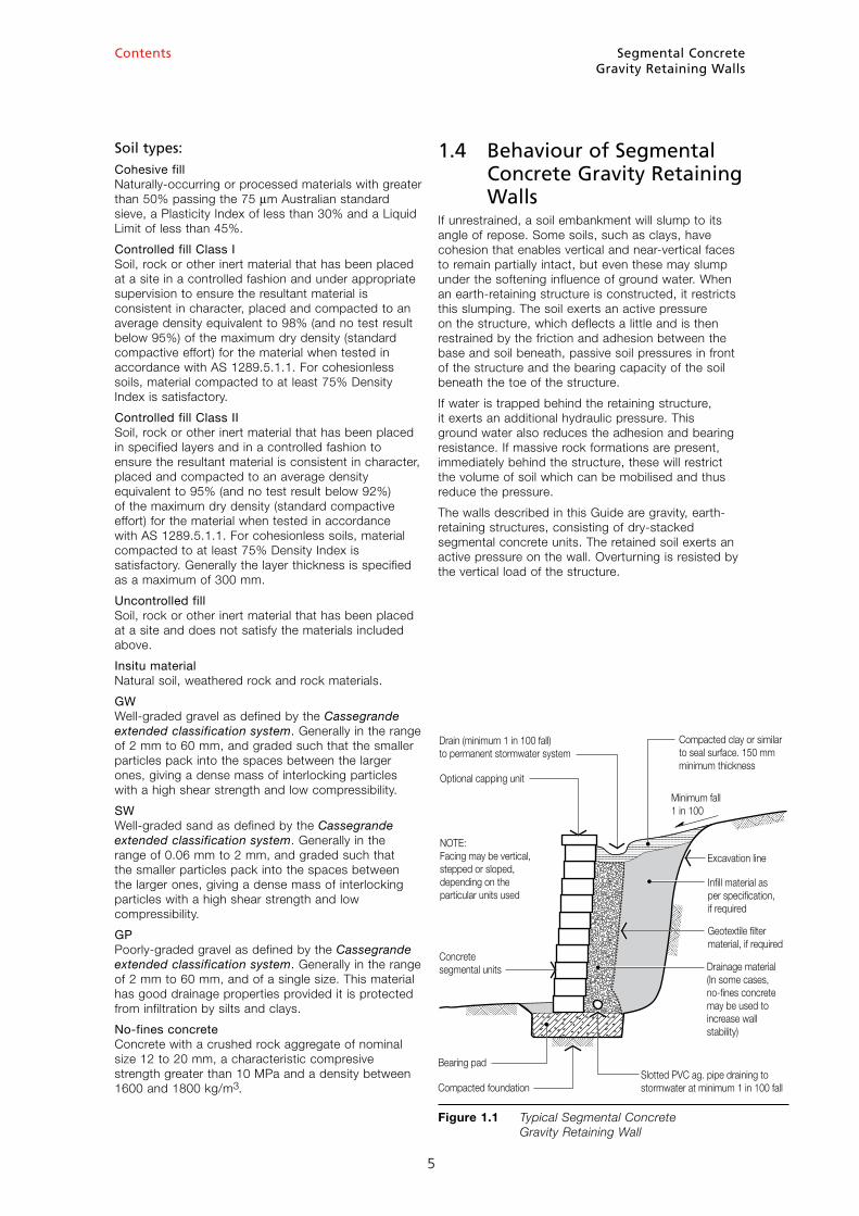
1.7 Global Slip FailureSoil-retaining structures must be checked for global slip failure around all potential slip surfaces or circles (Figure 1.2).
Designers often reduce the heights of retaining walls by splitting a single wall into two (or more) walls, thus terracing the site. Whilst this may assist in the design of the individual walls, it will not necessarily reduce the tendency for global slip failure around surfaces encompassing all or some of the retaining walls.
The designer should also take into account the effects of rock below or behind the structure in resisting slip failure.
Analysis for global slip is not included in this guide and it is recommended that designers carry out a separate check using commercially available software.
Segmental ConcreteGravity Retaining Walls
6
Contents
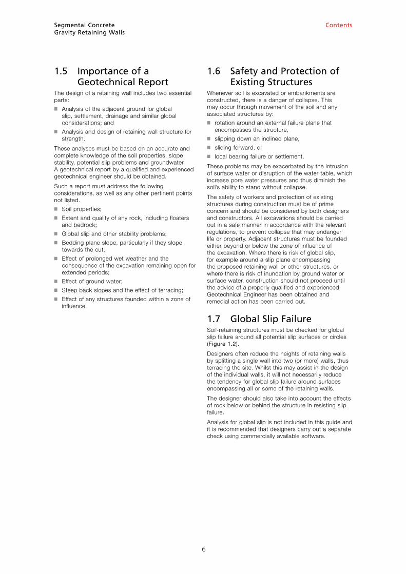
1.8 Differential SettlementTechniques to reduce or control the effects of differential settlement and the possibility of cracking include (Figure 1.3):■ Articulation of the wall (by discontinuing the normal
stretcher bond) at convenient intervals along the length.
■ Excavating, replacing and compacting areas of soft soil.
■ Limiting the stepping of the base to a maximum of 200 mm.
1.9 Importance of DrainageThis Guide assumes that a properly-functioning drainage system is effective in removing hydraulic pressure. If this is not the case, the designer will be required to design for an appropriate hydraulic load.
Based on an effective drainage system, it is common to use drained soil properties. For other situations, the designer must determine whether drained or undrained properties are appropriate. In particular, sea walls that may be subject to rapid draw-down (not covered in this Guide) require design using undrained soil properties.
1.10 Passive PressureFor completeness, this Guide gives consideration to passive pressure, which, in some circumstances, could contribute to the resistance to forward sliding.
Because the soil in front of a retaining wall can be excavated, eroded or otherwise disturbed, it is strongly recommended that passive pressure in front of the wall be ignored in design.
Segmental ConcreteGravity Retaining Walls
7
Globalslip plane
Primaryglobal slip plane
Secondaryglobal slipplane
Figure 1.2 Global Slip Failure
Wallheight,H
Limit steps toa maximum of200 mm to reducedifferential settlement
200 max
200 max
Differential settlement Use articulation joints to reduce differential settlement
Figure 1.3 Reduction and Control of Differential Settlement
Contents
2 Design Considerations
2.1 ScopeThis guide considers retaining walls founded on undisturbed material that is firm and dry and achieves the friction angle and cohesion noted for each particular soil type. It does not cover foundations exhibiting any of the following characteristics:■ Softness■ Poor drainage■ Fill■ Organic matter■ Variable conditions■ Heavily-cracked rock■ Aggressive soils.
If these conditions are present, they must be considered by the designer.
2.2 Limit State DesignThe design limit states to be considered are:■ strengths of the various components subject to
ultimate factored loads;■ stability of the structure as a whole subject to
ultimate factored loads; and■ serviceability of the structure and its components
subject to service loads.
Important Note: Serviceability considerations are beyond the scope of this Guide. However, the designer is strongly advised to consider closely the appropriate serviceability limits and the methods of satisfying these requirements in practical design. One common method is to limit the stresses in the foundation soil.
2.3 Partial Loading and Material FactorsPartial-loading and partial-material factors enable the designer to assign various levels of confidence to assumed or measured soil strengths, material strengths and resistance to deterioration, predictability of loads and consequence of failure of various structures.
There are several reasons for compatibility of loading factors between AS 4678-2002 and AS 1170 SAA Loading code, which applies to buildings(Note 3).■ Buildings are often constructed close to retaining
walls, and therefore apply loads on them. ■ Parts of buildings such as basement walls are often
required to withstand loads imposed by earth and soil.
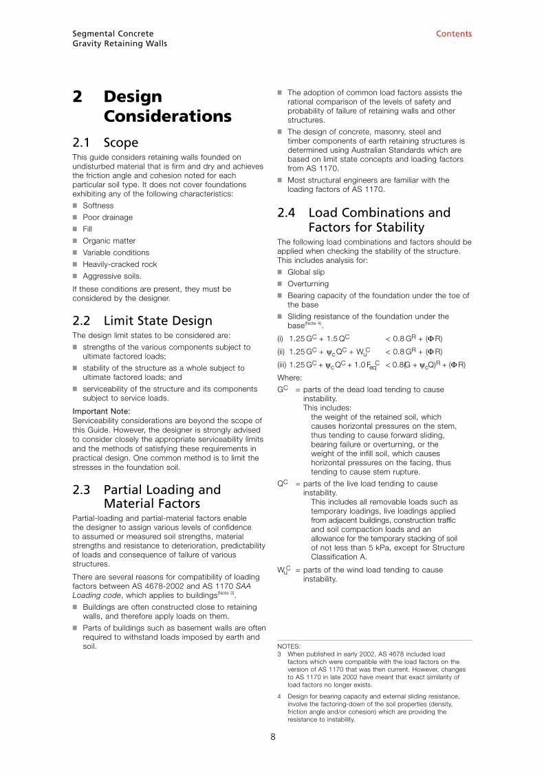
■ The adoption of common load factors assists the rational comparison of the levels of safety and probability of failure of retaining walls and other structures.
■ The design of concrete, masonry, steel and timber components of earth retaining structures is determined using Australian Standards which are based on limit state concepts and loading factors from AS 1170.
■ Most structural engineers are familiar with the loading factors of AS 1170.
2.4 Load Combinations and Factors for Stability The following load combinations and factors should be applied when checking the stability of the structure. This includes analysis for: ■ Global slip■ Overturning■ Bearing capacity of the foundation under the toe of
the base■ Sliding resistance of the foundation under the
base(Note 4).
(i) 1.25 GC + 1.5 QC < 0.8 GR + (Φ R)
(ii) 1.25 GC + ψc QC + WuC < 0.8 GR + (Φ R)
(iii) 1.25 GC + ψc QC + 1.0 FeqC < 0.8(G + ψcQ)R + (Φ R)
Where:
GC = parts of the dead load tending to cause instability. This includes: the weight of the retained soil, which causes horizontal pressures on the stem, thus tending to cause forward sliding, bearing failure or overturning, or the weight of the infill soil, which causes horizontal pressures on the facing, thus tending to cause stem rupture.
QC = parts of the live load tending to cause instability. This includes all removable loads such as temporary loadings, live loadings applied from adjacent buildings, construction traffic and soil compaction loads and an allowance for the temporary stacking of soil of not less than 5 kPa, except for Structure Classification A.
WuC = parts of the wind load tending to cause
instability.
Segmental ConcreteGravity Retaining Walls
8
NOTES: 3 When published in early 2002, AS 4678 included load factors which were compatible with the load factors on the version of AS 1170 that was then current. However, changes to AS 1170 in late 2002 have meant that exact similarity of load factors no longer exists.
4 Design for bearing capacity and external sliding resistance, involve the factoring-down of the soil properties (density, friction angle and/or cohesion) which are providing the resistance to instability.
Contents
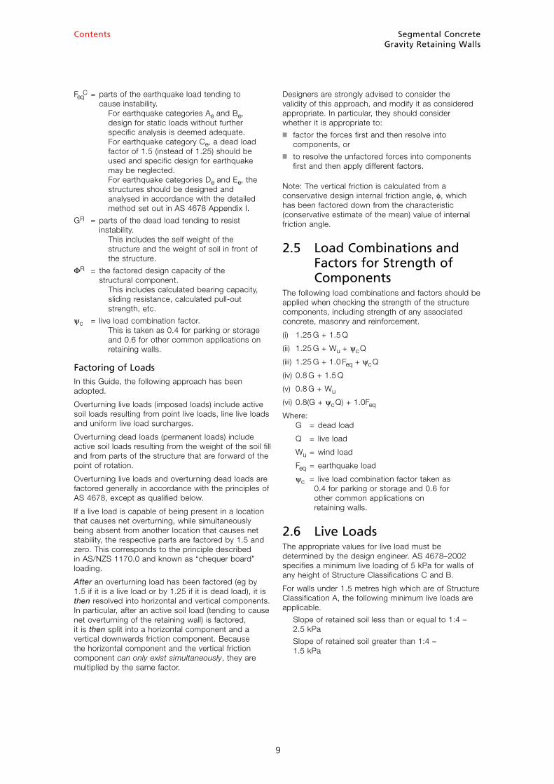
FeqC = parts of the earthquake load tending to
cause instability. For earthquake categories Ae and Be, design for static loads without further specific analysis is deemed adequate. For earthquake category Ce, a dead load factor of 1.5 (instead of 1.25) should be used and specific design for earthquake may be neglected. For earthquake categories De and Ee, the structures should be designed and analysed in accordance with the detailed method set out in AS 4678 Appendix I.
GR = parts of the dead load tending to resist instability. This includes the self weight of the structure and the weight of soil in front of the structure.
ΦR = the factored design capacity of the structural component. This includes calculated bearing capacity, sliding resistance, calculated pull-out strength, etc.
ψc = live load combination factor. This is taken as 0.4 for parking or storage and 0.6 for other common applications on retaining walls.
Factoring of LoadsIn this Guide, the following approach has been adopted.
Overturning live loads (imposed loads) include active soil loads resulting from point live loads, line live loads and uniform live load surcharges.
Overturning dead loads (permanent loads) include active soil loads resulting from the weight of the soil fill and from parts of the structure that are forward of the point of rotation.
Overturning live loads and overturning dead loads are factored generally in accordance with the principles of AS 4678, except as qualified below.
If a live load is capable of being present in a location that causes net overturning, while simultaneously being absent from another location that causes net stability, the respective parts are factored by 1.5 and zero. This corresponds to the principle described in AS/NZS 1170.0 and known as “chequer board” loading.
After an overturning load has been factored (eg by 1.5 if it is a live load or by 1.25 if it is dead load), it is then resolved into horizontal and vertical components. In particular, after an active soil load (tending to cause net overturning of the retaining wall) is factored, it is then split into a horizontal component and a vertical downwards friction component. Because the horizontal component and the vertical friction component can only exist simultaneously, they are multiplied by the same factor.
Designers are strongly advised to consider the validity of this approach, and modify it as considered appropriate. In particular, they should consider whether it is appropriate to:■ factor the forces first and then resolve into
components, or■ to resolve the unfactored forces into components
first and then apply different factors.
Note: The vertical friction is calculated from a conservative design internal friction angle, f, which has been factored down from the characteristic (conservative estimate of the mean) value of internal friction angle.
2.5 Load Combinations and Factors for Strength of ComponentsThe following load combinations and factors should be applied when checking the strength of the structure components, including strength of any associated concrete, masonry and reinforcement.
(i) 1.25 G + 1.5 Q
(ii) 1.25 G + Wu + ψc Q
(iii) 1.25 G + 1.0 Feq + ψc Q
(iv) 0.8 G + 1.5 Q
(v) 0.8 G + Wu
(vi) 0.8( G + ψc Q) + 1.0Feq
Where: G = dead load
Q = live load
Wu = wind load
Feq = earthquake load
ψc = live load combination factor taken as 0.4 for parking or storage and 0.6 for other common applications on retaining walls.
2.6 Live LoadsThe appropriate values for live load must be determined by the design engineer. AS 4678–2002 specifies a minimum live loading of 5 kPa for walls of any height of Structure Classifications C and B.
For walls under 1.5 metres high which are of Structure Classification A, the following minimum live loads are applicable.
Slope of retained soil less than or equal to 1:4 – 2.5 kPa
Slope of retained soil greater than 1:4 – 1.5 kPa
Segmental ConcreteGravity Retaining Walls
9
Segmental ConcreteGravity Retaining Walls
10
Contents
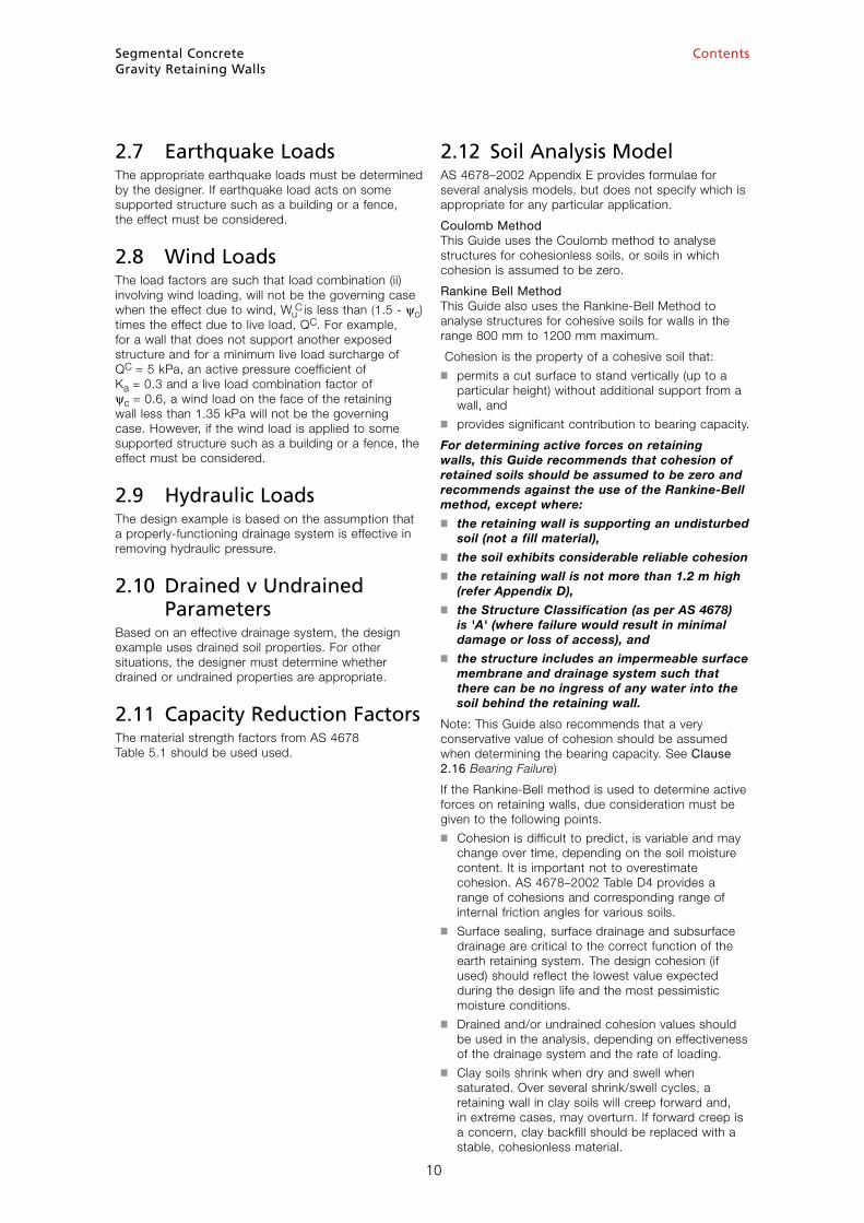
2.7 Earthquake LoadsThe appropriate earthquake loads must be determined by the designer. If earthquake load acts on some supported structure such as a building or a fence, the effect must be considered.
2.8 Wind LoadsThe load factors are such that load combination (ii) involving wind loading, will not be the governing case when the effect due to wind, Wu
C is less than (1.5 - ψc) times the effect due to live load, QC. For example, for a wall that does not support another exposed structure and for a minimum live load surcharge of QC = 5 kPa, an active pressure coefficient of Ka = 0.3 and a live load combination factor of ψc = 0.6, a wind load on the face of the retaining wall less than 1.35 kPa will not be the governing case. However, if the wind load is applied to some supported structure such as a building or a fence, the effect must be considered.
2.9 Hydraulic LoadsThe design example is based on the assumption that a properly-functioning drainage system is effective in removing hydraulic pressure.
2.10 Drained v Undrained ParametersBased on an effective drainage system, the design example uses drained soil properties. For other situations, the designer must determine whether drained or undrained properties are appropriate.
2.11 Capacity Reduction FactorsThe material strength factors from AS 4678 Table 5.1 should be used used.
2.12 Soil Analysis ModelAS 4678–2002 Appendix E provides formulae for several analysis models, but does not specify which is appropriate for any particular application.
Coulomb Method This Guide uses the Coulomb method to analyse structures for cohesionless soils, or soils in which cohesion is assumed to be zero.
Rankine Bell Method This Guide also uses the Rankine-Bell Method to analyse structures for cohesive soils for walls in the range 800 mm to 1200 mm maximum.
Cohesion is the property of a cohesive soil that:■ permits a cut surface to stand vertically (up to a
particular height) without additional support from a wall, and
■ provides significant contribution to bearing capacity.
For determining active forces on retaining walls, this Guide recommends that cohesion of retained soils should be assumed to be zero and recommends against the use of the Rankine-Bell method, except where:■ the retaining wall is supporting an undisturbed
soil (not a fill material),■ the soil exhibits considerable reliable cohesion■ the retaining wall is not more than 1.2 m high
(refer Appendix D),■ the Structure Classification (as per AS 4678)
is 'A' (where failure would result in minimal damage or loss of access), and
■ the structure includes an impermeable surface membrane and drainage system such that there can be no ingress of any water into the soil behind the retaining wall.
Note: This Guide also recommends that a very conservative value of cohesion should be assumed when determining the bearing capacity. See Clause 2.16 Bearing Failure)
If the Rankine-Bell method is used to determine active forces on retaining walls, due consideration must be given to the following points.■ Cohesion is difficult to predict, is variable and may
change over time, depending on the soil moisture content. It is important not to overestimate cohesion. AS 4678–2002 Table D4 provides a range of cohesions and corresponding range of internal friction angles for various soils.
■ Surface sealing, surface drainage and subsurface drainage are critical to the correct function of the earth retaining system. The design cohesion (if used) should reflect the lowest value expected during the design life and the most pessimistic moisture conditions.
■ Drained and/or undrained cohesion values should be used in the analysis, depending on effectiveness of the drainage system and the rate of loading.
■ Clay soils shrink when dry and swell when saturated. Over several shrink/swell cycles, a retaining wall in clay soils will creep forward and, in extreme cases, may overturn. If forward creep is a concern, clay backfill should be replaced with a stable, cohesionless material.
Segmental ConcreteGravity Retaining Walls
11
Contents
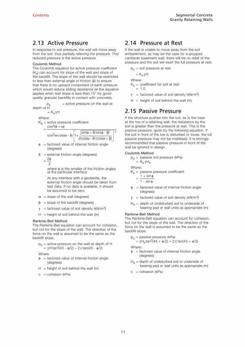
2.13 Active PressureIn response to soil pressure, the wall will move away from the soil, thus partially relieving the pressure. This reduced pressure is the active pressure.
Coulomb Method The Coulomb equation for active pressure coefficient (Ka) can account for slope of the wall and slope of the backfill. The slope of the wall should be restricted to less than external angle of friction (δ) to ensure that there is no upward component of earth pressure which would reduce sliding resistance (ie the equation applies when wall slope is less than 15° for good-quality granular backfills in contact with concrete).
pa = active pressure on the wall at depth of H = Ka γ H
Where: Ka = active pressure coefficient
= cos2(f + ω)
cos2ω cos(ω - δ) 1+
sin(f + δ) sin(f - β) 2
√cos(ω - δ) cos(ω + β)
f = factored value of internal friction angle (degrees)
δ = external friction angle (degrees)
= 2f 3 where f is the smaller of the friction angles at the particular interface
At any interface with a geotextile, the external friction angle should be taken from test data. If no data is available, it should be assumed to be zero.
ω = slope of the wall (degrees)
β = slope of the backfill (degrees)
γ = factored value of soil density (kN/m3)
H = height of soil behind the wall (m)
Rankine-Bell Method The Rankine-Bell equation can account for cohesion, but not for the slope of the wall. The direction of the force on the wall is assumed to be the same as the backfill slope.
pa = active pressure on the wall at depth of H = γ H tan2(45 - f/2) – 2 c tan(45 - f/2)
Where: f = factored value of internal friction angle (degrees)
H = height of soil behind the wall (m)
c = cohesion (kPa)
2.14 Pressure at RestIf the wall is unable to move away from the soil embankment, as may be the case for a propped cantilever basement wall, there will be no relief of the pressure and the soil will exert the full pressure at rest.
po = soil pressure at rest
= Ko γ H
Where: Ko = coefficient for soil at rest = 1.0
γ = factored value of soil density (kN/m3)
H = height of soil behind the wall (m)
2.15 Passive PressureIf the structure pushes into the soil, as is the case at the toe of a retaining wall, the resistance by the soil is greater than the pressure at rest. This is the passive pressure, given by the following equation. If the soil in front of the toe is disturbed or loose, the full passive pressure may not be mobilised. It is strongly recommended that passive pressure in front of the wall be ignored in design.
Coulomb Method pp = passive soil pressure (kPa) = Kp γ He
Where: Kp = passive pressure coefficient
= 1 + sin f
1 - sin f
f = factored value of internal friction angle (degrees)
γ = factored value of soil density (kN/m3)
He = depth of undisturbed soil to underside of bearing pad or wall units as appropriate (m)
Rankine-Bell Method The Rankine-Bell equation can account for cohesion, but not for the slope of the wall. The direction of the force on the wall is assumed to be the same as the backfill slope.
pp = passive pressure (kPa) = γ He tan2(45 + f/2) + 2 c tan(45 + f/2)
Where: f = factored value of internal friction angle (degrees)
He = depth of undisturbed soil to underside of bearing pad or wall units as appropriate (m)
c = cohesion (kPa)
11

Segmental ConcreteGravity Retaining Walls
12
Contents
2.16 Bearing FailureAs soil and water pressure are applied to the rear face of the structure, it will tilt forward and the soil under the toe is subjected to high bearing pressures. Bearing is often the critical mode of failure. The following theoretical approach is used to analyse this region for bearing pressure failure and is based on the Meyerhof method. This gives consideration to footing width, footing tilt and angle of applied load and is explained in a paper by Vesic titled Bearing Capacity of Shallow Footings in the Foundation Engineering Handbook.
Q = Bearing capacity of the foundation (kN) = qav LB
Where: qav= average bearing capacity based on factored soil properties (kPa)
B = actual width of bearing pad on foundation material (m)
LB = effective width of bearing pad on foundation material (m)
c = factored value of drained cohesion (kPa)
f = factored value of friction angle (radians)
γ = factored value of soil density (kN/m3)
He = depth of undisturbed soil to underside of bearing pad or wall units as appropriate (m)
Nc = (Nq - 1)cot f
Nq = eπ tan f tan 2[π/4 + f/2]
Nγ = 2(Nq + 1)tan f
Shape factors: ζc = 1.0 for rectangular bases
ζq = 1.0 for rectangular bases
ζγ = 1.0 for rectangular bases
Factors for inclined load: ζci = ζqi - (1 - ζqi) /(Nc tan f)
ζqi = [1 - P*/(Q* + LB c cot f)]2
ζγi = [1 - P*/(Q* + LB c cot f)]3
Factors for sloping bases: ζct = ζqt - (1 - ζqt) / (Nc tan f) =1.0 for level base
ζqt = (1 - α tan f)2 =1.0 for level base
ζγt = (1 - α tan f)2 =1.0 for level base
Q* = vertical load based on factored loads and soil properties
P* = horizontal load based on factored loads and soil properties
α = angle of base in radians = zero for level base
2.17 Sliding FailureAs soil and water pressure are applied to the rear face of the structure, the base of the wall or footing (if constructed) may slide forward. Such sliding action is resisted by the friction and adhesion between the foundation material and the base of the wall or footing, and the passive resistance of any soil in front of the toe.
Select the appropriate external friction angle, δ, that reflects the roughness of the base and its interlock with the foundation material. For a “rough” base, the external friction angle approaches the internal friction angle, f, of the soil. For a normal concrete surface, the external friction angle would approach ²/³ f.
“Rough” bases include:
■ Concrete units incorporating cores filled with crushed rock,
■ Concrete units with a lip that protrudes into the crushed rock,
■ No-fines concrete fill, and■ Where the base blocks are embedded in a concrete
foundation.
The designer should consider the validity of these assumptions.
The NCMA (National Concrete Masonry Association [USA]) has published test results that deal with the sliding resistance of concrete blocks on various soils. For smooth bases, with an internal friction angle, f = 35°, and external friction angle, δ= 23.3° and cohesion, c = 0, the method used in this Guide would yield 0.97 times the resistance calculated using the NCMA method. Although the agreement is not so close for other combinations, their use is infrequent and not recommended.
When considering passive resistance, note that material can be inadvertently removed from the toe of the wall.
F = Sliding resistance based on factored characteristic soil properties = Friction + adhesion + passive resistance = Q* tan δ + c B + Kp0.5 γ He
2
Where:
Q* = vertical load based on factored loads and soil properties
δ = external friction angle of the soil calculated from the factored internal friction angle.)
B = actual base width (m)
c = factored value of adhesion (kPa)
Kp = passive pressure coefficient
γ = factored value of soil density (kN/m3)
He = depth of undisturbed soil to underside of bearing pad or wall units as appropriate (m)
12
= c Nc ζc ζci ζct + γ He Nq ζq ζqi ζqt + 0.5 γ B Nγ ζγ ζγi ζγt
Segmental ConcreteGravity Retaining Walls
13
Contents
2.18 OverturningAS 4678-2002 does not specify an analysis method for overturning. This Guide considers overturning about a point level with the underside of the facing units and a nominated distance behind the toe of the facing units. If this nominated distance is one third of the base width and the factor against overturning is calculated as 1.0, this corresponds to the reaction being situated within the middle third of the base at ultimate loads.
2.19 Global slipAS 4678-2002 Clause 3.2 requires stability (including rotation) to be checked.
The design example does not include analysis for global slip.
2.20 Foundation MaterialIn some cases, weak foundations with low friction angles lead to excessively-high bearing pressures or low resistance to sliding. To avoid this situation, one design option is to remove any material with a low friction angle and replace it with a more suitable material with a characteristic friction angle of at least 35°. Typically, compacted road base would be suitable in such an application. If the foundation soil does not possess suitable properties, it should be excavated and replaced with compacted road base to a depth such that sliding and bearing resistance can be achieved. In all cases, an experienced civil or geotechnical engineer should be engaged to determine the appropriate soil properties.
2.21 Lean BackConsistent with AS 4678–2002, this guide does not cover the design of revetments with a lean back of 20° or more from vertical.
3 AppendicesThe following Appendices are included:
Appendix A – Design Example 14
Appendix B – Site Investigation 21
Appendix C – Construction Specification 23
Appendix D – Height Table for Walls 800 to 1200 mm high 26
Appendix E – Details for Walls up to 800 mm high 28
13
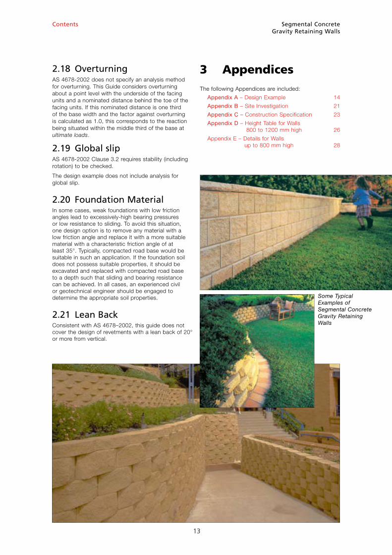
Some Typical Examples of Segmental Concrete Gravity Retaining Walls
Segmental ConcreteGravity Retaining Walls
14
Contents
Appendix A Design Example
The following example demonstrates the method used to design a typical segmental concrete masonry gravity retaining wall in accordance with AS 4678 and the design considerations set out in this Guide. It may also be used to check the suitability of commercially-available design software that is intended to be based on AS 4678 and on this Guide.
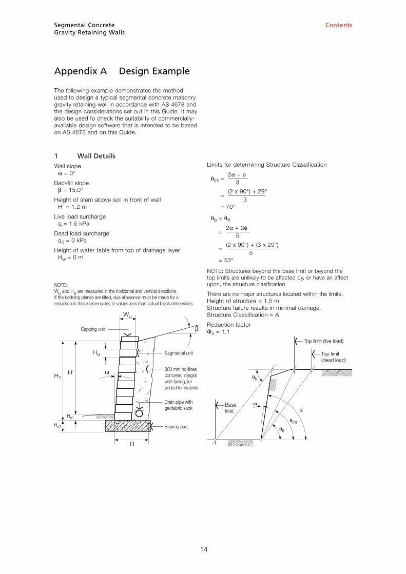
1 Wall DetailsWall slope ω = 0°
Backfill slope β = 15.0°
Height of stem above soil in front of wall H’ = 1.2 m
Live load surcharge ql = 1.5 kPa
Dead load surcharge qd = 0 kPa
Height of water table from top of drainage layer Hw = 0 m
Limits for determining Structure Classification
θtm = 2α + f
3
= (2 x 90°) + 29°
3 = 70°
θb = θtf
= 2α + 3f
5
= (2 x 90°) + (3 x 29°)
5 = 53°
NOTE: Structures beyond the base limit or beyond the top limits are unlikely to be affected by, or have an affect upon, the structure clasification
There are no major structures located within the limits. Height of structure < 1.5 m Structure failure results in minimal damage. Structure Classification = A
Reduction factor Φn = 1.1
14
Baselimit
Top limit(dead load)
Top limit (live load)
H1H'
B
Hu
Wu
Capping unit
Segmental unit
300 mm no-�nesconcrete, integralwith facing, foradded for stability
Drain pipe withgeofabric sock
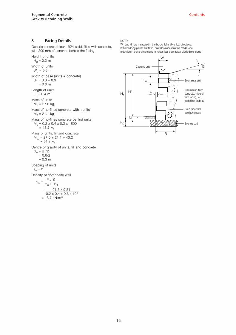
NOTE:Wu and Hu are measured in the horizontal and vertical directions.If the bedding planes are tilted, due allowance must be made for areduction in these dimensions to values less than actual block dimensions
Bearing pad
He1
He2
Segmental ConcreteGravity Retaining Walls
15
Contents
2 Earthquake ConsiderationsLocation Sydney
Acceleration coefficient a = 0.08
Soil profile Not more than 30 m of firm clay
Site factor s = 1.0
Earthquake design category = Ber ∴ Design for static loads without further specific analysis
3 Load FactorsLoad factor on overturning dead loads Gdo = 1.25
Load factor on overturning live loads Glo = 1.5
Load factor on resisting dead loads Gdr = 0.8
Load factor on resisting live loads Glr = 0.0
4 Infill PropertiesIn order to achieve increased stability, the infill material shall be 300 mm of no-fines concrete, which adheres to the facing units forming a solid mass.
5 Retained Soil PropertiesSoil description Stiff sandy clay Insitu
Characteristic internal angle of friction fr = 29°
Design uncertainity factor for friction Φufr = 0.85
Design angle of friction fr* = tan-1[(tan fi)Φufr] = tan-1[(tan 29°)0.85] = 25.2°
Characteristic cohesion cr = 5.0 kPa
Design uncertainty factor for cohesion Φucr = 0.70
Design cohesion cr* = cr Φucr = 5.0 x 0.70 = 3.5 kPa Assume zero for design
Soil density γr* = 19.6 kN/m3
Design external friction angle (soil to concrete interface)
δr* = 2 fr*
3 = 16.8°
6 Foundation Soil PropertiesSoil description Reconstruct the foundation to improve properties. Use crushed sandstone fill Controlled fill, Class 2
Characteristic internal angle of friction ff = 35°
Design uncertainity factor for friction Φuff = 0.90
Design angle of friction ff* = tan-1[(tan ff)Φuff] = tan-1[(tan 35°)0.90] = 32.2°
Characteristic cohesion cf = 3.0 kPa
Design uncertainty factor for cohesion Φucf = 0.75
Design cohesion cf* = cf Φucf = 3.0 x 0.75 = 2.3 kPa for bearing and zero for sliding
Soil density γf* = 18.6 kN/m3
7 Bearing Pad PropertiesSoil description Cement-stabilised crushed rock Class 1 controlled fill
Characteristic internal angle of friction fb = 40°
Design uncertainity factor for friction Φufb = 0.95
Design internal angle of friction fb* = tan-1[(tan fb)Φufb] = tan-1[(tan 40°)0.95] = 38.6°
Characteristic cohesion/adhesion cb = 0 kPa
Design uncertainty factor for cohesion/adhesion Φucb = 0.90
Design cohesion/adhesion cb* = cb Φucb = 0 x 0.90 = 0 kPa
Density γb* = 20.0 kN/m3
15
Segmental ConcreteGravity Retaining Walls
16
Contents
8 Facing DetailsGeneric concrete block, 40% solid, filled with concrete, with 300 mm of concrete behind the facing
Height of units Hu = 0.2 m
Width of units Wu = 0.3 m
Width of base (units + concrete) B1 = 0.3 + 0.3 = 0.6 m
Length of units Lu = 0.4 m
Mass of units Mu = 27.0 kg
Mass of no-fines concrete within units Ms = 21.1 kg
Mass of no-fines concrete behind units Mc = 0.2 x 0.4 x 0.3 x 1800 = 43.2 kg
Mass of units, fill and concrete Msu = 27.0 + 21.1 + 43.2 = 91.3 kg
Centre of gravity of units, fill and concrete Gu ≈ B1/2 = 0.6/2 = 0.3 m
Spacing of units su = 0
Density of composite wall
γsu = Msu g
Hu Lu B1
= 91.3 x 9.81 0.2 x 0.4 x 0.6 x 103 = 18.7 kN/m3
16
H1H'
B
Hu
Wu
Capping unit
Segmental unit
300 mm no-�nesconcrete, integralwith facing, foradded for stability
Drain pipe withgeofabric sock
NOTE:Wu and Hu are measured in the horizontal and vertical directions.If the bedding planes are tilted, due allowance must be made for areduction in these dimensions to values less than actual block dimensions
Bearing pad
He1
He2
Segmental ConcreteGravity Retaining Walls
17
Contents
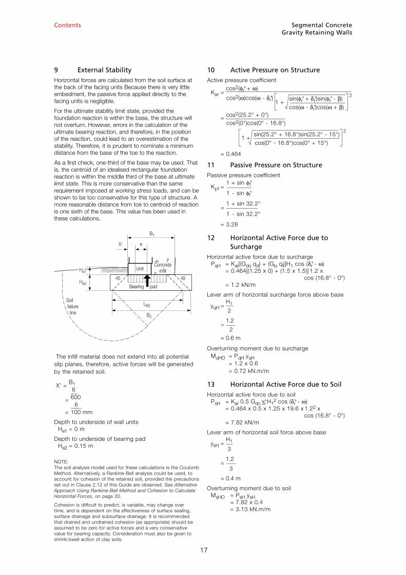
9 External StabilityHorizontal forces are calculated from the soil surface at the back of the facing units Because there is very little embedment, the passive force applied directly to the facing units is negligible.
For the ultimate stability limit state, provided the foundation reaction is within the base, the structure will not overturn. However, errors in the calculation of the ultimate bearing reaction, and therefore, in the position of the reaction, could lead to an overestimation of the stability. Therefore, it is prudent to nominate a minimum distance from the base of the toe to the reaction.
As a first check, one-third of the base may be used. That is, the centroid of an idealised rectangular foundation reaction is within the middle third of the base at ultimate limit state. This is more conservative than the same requirement imposed at working stress loads, and can be shown to be too conservative for this type of structure. A more reasonable distance from toe to centroid of reaction is one sixth of the base. This value has been used in these calculations.
The infill material does not extend into all potential slip planes, therefore, active forces will be generated by the retained soil.
X’ = B1 6 = 600 6 = 100 mm
Depth to underside of wall units He1 = 0 m
Depth to underside of bearing pad He2 = 0.15 m
NOTE: The soil analysis model used for these calculations is the Coulomb Method. Alternatively, a Rankine-Bell analysis could be used, to account for cohesion of the retained soil, provided the precautions set out in Clause 2.12 of this Guide are observed. See Alternative Approach Using Rankine-Bell Method and Cohesion to Calculate Horizontal Forces, on page 20.
Cohesion is difficult to predict, is variable, may change over time, and is dependent on the effectiveness of surface sealing, surface drainage and subsurface drainage. It is recommended that drained and undrained cohesion (as appropriate) should be assumed to be zero for active forces and a very conservative value for bearing capacity. Consideration must also be given to shrink/swell action of clay soils.
10 Active Pressure on StructureActive pressure coefficient
Kar = cos2(fr* + ω)
cos2(ω)cos(ω - δr*) 1 + sin(fr* + δr*)sin(fr* - β) 2
cos(ω - δr*)cos(ω + β)
= cos2(25.2° + 0°) cos2(0°)cos(0° - 16.8°)
1 + sin(25.2° + 16.8°)sin(25.2° - 15°) 2
cos(0° - 16.8°)cos(0° + 15°)
= 0.464
11 Passive Pressure on StructurePassive pressure coefficient
Kpf = 1 + sin ff*
1 - sin ff*
= 1 + sin 32.2°
1 - sin 32.2°
= 3.28
12 Horizontal Active Force due to SurchargeHorizontal active force due to surcharge PqH = Kar[(Gdo qd) + (Glo ql)]H1 cos (δr* - ω) = 0.464[(1.25 x 0) + (1.5 x 1.5)] 1.2 x cos (16.8° - 0°) = 1.2 kN/m
Lever arm of horizontal surcharge force above base
yqH = H1
2
= 1.2
2 = 0.6 m
Overturning moment due to surcharge MqHO = PqH yqH = 1.2 x 0.6 = 0.72 kN.m/m
13 Horizontal Active Force due to SoilHorizontal active force due to soil PsH = Kar 0.5 Gdo γr* H1
2 cos (δr* - ω) = 0.464 x 0.5 x 1.25 x 19.6 x 1.22 x cos (16.8° - 0°) = 7.82 kN/m
Lever arm of horizontal soil force above base
ysH = H1
3
= 1.2
3
= 0.4 m
Overturning moment due to soil MsHO = PsH ysH = 7.82 x 0.4 = 3.13 kN.m/m
17
Soil failure line
UnitConcrete
in�ll
Bearing pad
He1
He2
LB2
B2
B1
eX'
45 45
Segmental ConcreteGravity Retaining Walls
18
Contents
14 Horizontal Passive Force
Passive force on underside of wall unit Pp(k+b)H = Kpf 0.5 Gdo γf* He1
2 = 3.28 x 0.5 x 0.8 x 18.6 x 02 = 0 kN/m
Lever arm of passive horizontal soil force above base
ypHR = He1
3
= 0
3
= 0 m
Restoring moment due to passive horizontal soil force MpHR = Pp(k+b)H ypHR = 0 x 0 = 0 kN.m/m
15 Weight of Stem UnitsWeight of stem units PuV = GdR γsu H B1 = 0.8 x 18.7 x 1.2 x 0.6 = 10.75 kN/m
Lever arm on weight stem units
XuV = H tanω + B1 - X’
2 2
= 1.2 tan0° + 0.6 - 0.1 2 2 = 0.2 m
Restoring moment due to weight of stem units MuvR = PuV XuV = 10.75 x 0.2 = 2.15 kN.m/m
16 Vertical Active Force due to SurchargeTo calculate the vertical component of soil friction, the factored horizontal force component is multiplied by tan(δr* - ω)
That is, this force effectively has a load factor of 1.5 applied, even though it has a restoring effect.
Vertical component of active force due to surcharge PqV = PqH tan(δr* - ω) = 1.2 x tan(16.8° - 0°) = 0.36 kN/m
Lever arm of vertical component of active surcharge
XqV = H tan ω + B1 - X’ 2
= 1.2 tan0° + 0.6 - 0.1
2 = 0.5 m
Restoring moment due to vertical component of active surcharge MqVR = PqV XqV = 0.36 x 0.5 = 0.18 kN.m/m
17 Vertical Active Force due to Soil WeightTo calculate the vertical component of soil friction, the factored horizontal force component is multiplied by tan(δr* - ω)
That is, this force effectively has a load factor of 1.25 applied, even though it has a restoring effect.
Vertical component of active force due to soil weight PsV = PsH tan(δr* - ω) = 7.82 x tan(16.8° - 0°) = 2.36 kN/m
Lever arm of vertical component of active soil weight
XsV = H tan ω + B1 - X’ 2
= 1.2 tan0° + 0.6 - 0.1
2 = 0.5 m
Restoring moment due to vertical component of active soil weight MsVR = PsV XsV = 2.36 x 0.5 = 1.18 kN.m/m
18 Base SlidingSelect the appropriate external friction angle, δ, that reflects the roughness of the base and its interlock with the foundation material. For a rough base, the external friction angle approaches the internal friction angle, f, of the soil. For a normal concrete surface, the external friction angle would approach ²/³ f. The designer should consider the validity of this assumption.
Friction resistance Pfr = Φn(PuV + PqV + PsV) tan fb* = 1.1(10.75 + 0.36 + 2.36) tan 38.6° = 11.8 kN/m
Base adhesion Pba = Φn B1 c*b = 1.1 x 0.6 x 0 = 0 kN/m
Passive force in front of base and key (if any) PpH = Φn Pp(k+b)H = 1.0 x 0 = 0 kN/m
Total sliding resistance PsR = Pfr + Pba + PpH = 11.8 + 0 + 0 = 11.8 kN/m
Sliding force PbH = PqH + PsH = 1.2 + 7.82 = 9.0 kN/m < 11.8 kN/m OK
NOTE: Sliding should also be checked at the interface of any soil strata beneath the structure. It is strongly recommended that passive pressure in front of the wall be ignored in design.
18
Segmental ConcreteGravity Retaining Walls
19
Contents
19 OverturningOverturning has been checked about a point that is one-sixth of the base width from the toe and at the level of the underside of the wall units.
Resisting moments MR = Φn(MuVR + MqVR + MsVR) = 1.1(2.15 + 0.18 + 1.18) = 3.86 kNm/m
Overturning moments MO = MqHO + MsHO
= 0.72 + 3.13 = 3.85 kNm/m < 3.86 kNm/m OK
20 Bearing at Underside of Bearing Pad
Depth of embedment, He = He2 = 0.15 m Actual width of base, B = B1 + He2 + He2 = 0.6 + 0.15 + 0.15 = 0.9 m
Ratio of horizontal loads to vertical loads
PH =
PqH + PsH
PV PuV + PqV + PsV
= 1.2 + 7.82
10.75 + 0.36 + 2.36
= 0.669
Eccentricity
e = B1
- X’ - MR - Mo
2 Pv
= 0.6 - 0.1 -
3.86 - 3.85
2 10.75 +0.36 + 2.36
= 0.199 m
Bearing width of stem on bearing pad LB1 = B1 - 2e = 0.6 - (2 x 0.199) = 0.20 m
Bearing width of bearing pad on foundation LB = LB2 = LB1 + He2 + He2 = 0.20 + 0.15 + 0.15 = 0.50 m
Bearing capacity factors Nq = eπ tanff* tan2(π/4 + ff*/2) = eπ tan32.2° tan2(π/4 + 32.2°/2) = 23.8
Nc = (Nq - 1)cot ff* = (23.8 - 1)cot 32.2° = 36.2
Nγ = 2(Nq + 1)tan ff* = 2(23.8 + 1)tan 32.2° = 31.2
ζq = 1.0
ζqi = 1 -
PH 2
PV + LB2 cf* cot ff* = 1 -
9.02 2
13.5 + 0.50 x 2.3 x cot 32.2°
= 0.173
ζqt = [1 - αtan ff*]2
= [1 - 0tan 32.2°]2
= 1.0
ζc = 1.0
ζci = ζqi -
1 - ζqi
Nc tan ff* = 0.17 - 1 - 0.17
36.2 x tan 32.2°
= 0.13
ζct = ζqt -
1 - ζqt
Nc tan ff* = 1.0 - 1 - 1.0
36.2 x tan 32.2°
= 1.0
ζγ = 1.0
ζγi = 1 -
PH 3
PV + LB2 cf* cot ff* = 1 - 9.02 3
13.5 + 0.50 x 2.3 x cot 32.2°
= 0.07
ζγt = [1 - αtan ff*]2
= [1 - 0tan 32.2°]2
= 1.0
Average bearing strength capacity* PVcap = Φn LB[(cf* Nc ζc ζci ζct) + (γf* He Nq ζq ζqi ζqt) + (0.5 γf* B' Nγ ζγ ζγi ζγt)] = 19.2 kN/m
Applied vertical force PV = 13.5 kN/m < 19.2 kN/m OK
* Note: In the formula for average bearing strength capacity at the underside of the bearing pad, LB is the effective width at the bearing pad/foundation interface, accounting for eccentricity. B' is the maximum of B and LB.
19
Segmental ConcreteGravity Retaining Walls
20
Contents
Alternative Approach Using Rankine–Bell Method and Cohesion to Calculate Horizontal ForcesNote: See limitations given in Clause 2.12 of this Guide.
Active pressure coefficient (Rankine Method – level backfill)
Kar = 1 - sin fr 1 + sin fr
= 1 - sin25.2°
1 + sin25.2° = 0.402
Active pressure coefficient (Rankine Method – sloping backfill)
Kar = cos β[cos β- (cos2 β- cos2 f)0.5] [cos β+ (cos2 β- cos2 f)0.5]
= cos15°[cos15° - (cos2 15° - cos2 25.3°)0.5]
[cos15° + (cos2 15° - cos2 25.3°)0.5] = 0.464
Design active pressure coefficient Kar = 0.464
Net pressure at the surface considering surcharge and cohesion Pat = Kar(Gdo qd + Glo ql) - 2 cr* Kar
2
= 0.464[(1.25 x 0) + (1.5 x 1.5)] - 2 x 3.5 x 0.4642 = 0.46 kPa
Net pressure at the surface considering surcharge and cohesion is negative.
If the net pressure at the surface is positive, tension cracks will not be able to form in the retained soil. This occurs when the surcharge is relatively high and/or the cohesion is relatively low.
In this example, cohesion will be ignored and the retaining wall will be designed for both soil and surcharge using the Coulomb formula.
If the net pressure at the surface is negative, tension cracks may form in the retained soil. The following expression permits the calculation of the depth of tension cracks, allowing for the combined efffects of cohesion and surcharge.
At this depth, surcharge load has been dissipated in overcoming the soil cohesion. That is, the soil (supporting both the surcharge and its own weight) may stand alone to this depth, without the aid of a retaining wall. Below this depth, there is no further need to consider surcharge. Tension cracks in the retained soil may fill with water and exert a pressure on the top part of the wall.
Depth of cracks
Hc = 2 c' (γ Kar
0.5) - (Gdo qd + Glo ql) Gdo γ
= 2 x 3.5 (19.6 x 0.4640.5) - (1.25 x 0) + (1.5 x 1.5) 1.25 x 19.6 = 0.432 m
The active forces due to soil and surcharge act at an angle generally greater than the backfill slope.
It is commonly assumed, in the Rankine Method, that, for cohesionless soils, the direction of force is the same as the backfill slope, β.
It is commonly assumed, in the Rankine Method, that, for cohesive soils, the direction of force is horizontal. It is conservative to assume a horizontal active force.
Therefore, in this analysis, all active forces are assumed to act horizontally for all combinations of friction and cohesion.
Horizontal active force due to water in tension cracks P'aw = 0.5 Gw γw z0
2 = 0.5 x 1.0 x 9.81 x 0.4322 = 3.35 kN/m
Horizontal active force due to soil P'a = 0.5 Kar Gdo γr (H - z0)2 = 0.5 x 0.464 x 1.25 x 19.6(1.200 - 0.471)2 = 0.92 kN/m
Vertical lever arm of horizontal soil load above toe yqh = H/3 = 1.200/3 = 0.400 m
Vertical lever arm of horizontal water load above toe yqh = H - 0.667 Hw
= 1.200 - (0.667 x 0.432) = 0.400 m
Segmental ConcreteGravity Retaining Walls
21
Contents
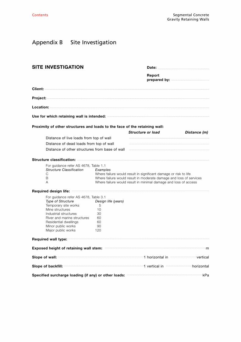
Appendix B Site Investigation
SITE INVESTIGATION Date:
Report prepared by:
Client:
Project:
Location:
Use for which retaining wall is intended:
Proximity of other structures and loads to the face of the retaining wall:
Structure or load Distance (m)
Distance of live loads from top of wall
Distance of dead loads from top of wall
Distance of other structures from base of wall
Structure classification:
For guidance refer AS 4678, Table 1.1 Structure Classification Examples C Where failure would result in significant damage or risk to life B Where failure would result in moderate damage and loss of services A Where failure would result in minimal damage and loss of access
Required design life:
For guidance refer AS 4678, Table 3.1 Type of Structure Design life (years) Temporary site works 5 Mine structures 10 Industrial structures 30 River and marine structures 60 Residential dwellings 60 Minor public works 90 Major public works 120
Required wall type:
Exposed height of retaining wall stem: m
Slope of wall: 1 horizontal in vertical
Slope of backfill: 1 vertical in horizontal
Specified surcharge loading (if any) or other loads: kPa
ContentsSegmental ConcreteGravity Retaining Walls
22
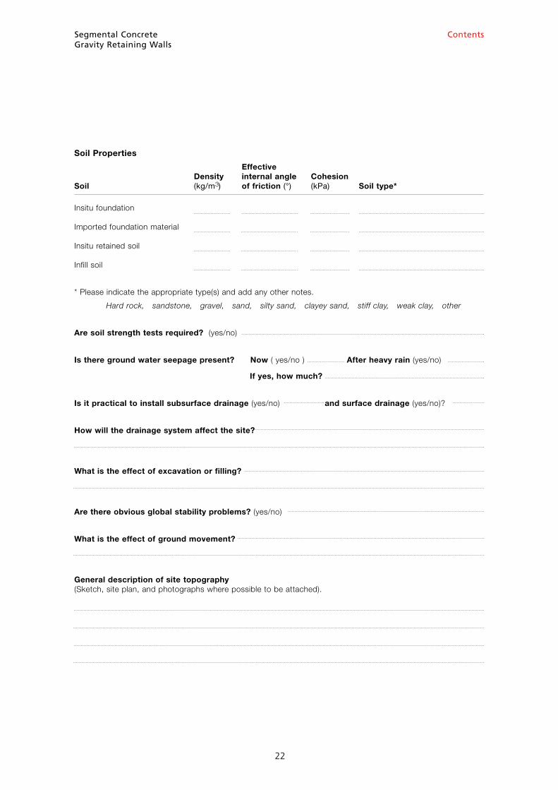
Soil Properties
Effective Density internal angle Cohesion Soil (kg/m3) of friction (°) (kPa) Soil type*
Insitu foundation
Imported foundation material
Insitu retained soil
Infill soil
* Please indicate the appropriate type(s) and add any other notes.
Hard rock, sandstone, gravel, sand, silty sand, clayey sand, stiff clay, weak clay, other
Are soil strength tests required? (yes/no)
Is there ground water seepage present? Now ( yes/no ) After heavy rain (yes/no)
If yes, how much?
Is it practical to install subsurface drainage (yes/no) and surface drainage (yes/no)?
How will the drainage system affect the site?
What is the effect of excavation or filling?
Are there obvious global stability problems? (yes/no)
What is the effect of ground movement?
General description of site topography (Sketch, site plan, and photographs where possible to be attached).
Segmental ConcreteGravity Retaining Walls
23
Contents
23
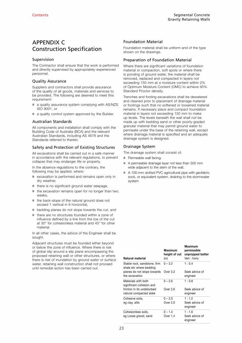
APPENDIX C Construction Specification
SupervisionThe Contractor shall ensure that the work is performed and directly supervised by appropriately-experienced personnel.
Quality AssuranceSuppliers and contractors shall provide assurance of the quality of all goods, materials and services to be provided. The following are deemed to meet this requirement:■ a quality assurance system complying with AS/NZS
ISO 9001, or■ a quality control system approved by the Builder.
Australian StandardsAll components and installation shall comply with the Building Code of Australia (BCA) and the relevant Australian Standards, including AS 4678 and the Standards referred to therein.
Safety and Protection of Existing StructuresAll excavations shall be carried out in a safe manner in accordance with the relevant regulations, to prevent collapse that may endanger life or property.
In the absence regulations to the contrary, the following may be applied, where:■ excavation is performed and remains open only in
dry weather,■ there is no significant ground water seepage,■ the excavation remains open for no longer than two
weeks,■ the back-slope of the natural ground does not
exceed 1 vertical in 6 horizontal, ■ bedding planes do not slope towards the cut, and ■ there are no structures founded within a zone of
influence defined by a line from the toe of the cut at 30° for cohesionless material and 45° for other material.
In all other cases, the advice of the Engineer shall be sought.
Adjacent structures must be founded either beyond or below the zone of influence. Where there is risk of global slip around a slip plane encompassing the proposed retaining wall or other structures, or where there is risk of inundation by ground water or surface water, retaining wall construction shall not proceed until remedial action has been carried out.
Foundation MaterialFoundation material shall be uniform and of the type shown on the drawings.
Preparation of Foundation MaterialWhere there are significant variations of foundation material or compaction, soft spots or where there is ponding of ground water, the material shall be removed, replaced and compacted in layers not exceeding 150 mm at a moisture content within 2% of Optimum Moisture Content (OMC) to achieve 95% Standard Proctor density.
Trenches and footing excavations shall be dewatered and cleaned prior to placement of drainage material or footings such that no softened or loosened material remains. If necessary place and compact foundation material in layers not exceeding 150 mm to make up levels. The levels beneath the wall shall not be made up with bedding sand or other poorly-graded granular material that may permit ground water to permeate under the base of the retaining wall, except where drainage material is specified and an adequate drainage system is designed.
Drainage System The drainage system shall consist of:■ Permeable wall facing.■ A permeable drainage layer not less than 300 mm
wide adjacent to the stem of the wall. ■ A 100-mm slotted PVC agricultural pipe with geofabric
sock, or equivalent system, draining to the stormwater system
Maximum Maximum permissible height of cut unpropped batterNatural material (m) Vert : horiz
Stable rock, sandstone, firm 0 – 3.2 1 : 0.4 shale etc where bedding planes do not slope towards Over 3.2 Seek advice of the excavation engineer
Materials with both 0 – 2.6 1 : 0.8 significant cohesion and friction in its undisturbed Over 2.6 Seek advice of natural compacted state engineer
Cohesive soils, 0 – 2.0 1 : 1.2 eg clay, silts Over 2.0 Seek advice of engineer
Cohesionless soils, 0 – 1.4 1 : 1.6 eg Loose gravel, sand Over 1.4 Seek advice of engineer
Segmental ConcreteGravity Retaining Walls
24
Contents
24
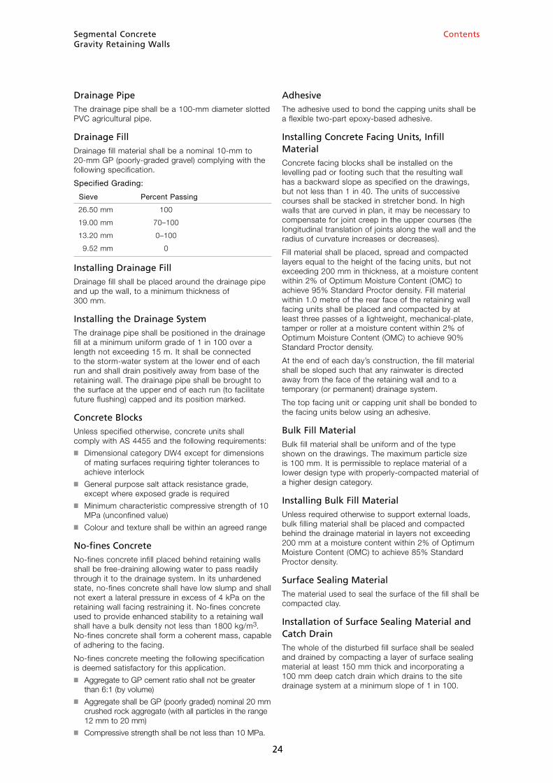
Drainage PipeThe drainage pipe shall be a 100-mm diameter slotted PVC agricultural pipe.
Drainage FillDrainage fill material shall be a nominal 10-mm to 20-mm GP (poorly-graded gravel) complying with the following specification.
Specified Grading:
Sieve Percent Passing
26.50 mm 100
19.00 mm 70–100
13.20 mm 0–100
9.52 mm 0
Installing Drainage FillDrainage fill shall be placed around the drainage pipe and up the wall, to a minimum thickness of 300 mm.
Installing the Drainage SystemThe drainage pipe shall be positioned in the drainage fill at a minimum uniform grade of 1 in 100 over a length not exceeding 15 m. It shall be connected to the storm-water system at the lower end of each run and shall drain positively away from base of the retaining wall. The drainage pipe shall be brought to the surface at the upper end of each run (to facilitate future flushing) capped and its position marked.
Concrete BlocksUnless specified otherwise, concrete units shall comply with AS 4455 and the following requirements:■ Dimensional category DW4 except for dimensions
of mating surfaces requiring tighter tolerances to achieve interlock
■ General purpose salt attack resistance grade, except where exposed grade is required
■ Minimum characteristic compressive strength of 10 MPa (unconfined value)
■ Colour and texture shall be within an agreed range
No-fines ConcreteNo-fines concrete infill placed behind retaining walls shall be free-draining allowing water to pass readily through it to the drainage system. In its unhardened state, no-fines concrete shall have low slump and shall not exert a lateral pressure in excess of 4 kPa on the retaining wall facing restraining it. No-fines concrete used to provide enhanced stability to a retaining wall shall have a bulk density not less than 1800 kg/m3. No-fines concrete shall form a coherent mass, capable of adhering to the facing.
No-fines concrete meeting the following specification is deemed satisfactory for this application.■ Aggregate to GP cement ratio shall not be greater
than 6:1 (by volume)■ Aggregate shall be GP (poorly graded) nominal 20 mm
crushed rock aggregate (with all particles in the range 12 mm to 20 mm)
■ Compressive strength shall be not less than 10 MPa.
AdhesiveThe adhesive used to bond the capping units shall be a flexible two-part epoxy-based adhesive.
Installing Concrete Facing Units, Infill Material Concrete facing blocks shall be installed on the levelling pad or footing such that the resulting wall has a backward slope as specified on the drawings, but not less than 1 in 40. The units of successive courses shall be stacked in stretcher bond. In high walls that are curved in plan, it may be necessary to compensate for joint creep in the upper courses (the longitudinal translation of joints along the wall and the radius of curvature increases or decreases).
Fill material shall be placed, spread and compacted layers equal to the height of the facing units, but not exceeding 200 mm in thickness, at a moisture content within 2% of Optimum Moisture Content (OMC) to achieve 95% Standard Proctor density. Fill material within 1.0 metre of the rear face of the retaining wall facing units shall be placed and compacted by at least three passes of a lightweight, mechanical-plate, tamper or roller at a moisture content within 2% of Optimum Moisture Content (OMC) to achieve 90% Standard Proctor density.
At the end of each day’s construction, the fill material shall be sloped such that any rainwater is directed away from the face of the retaining wall and to a temporary (or permanent) drainage system.
The top facing unit or capping unit shall be bonded to the facing units below using an adhesive.
Bulk Fill MaterialBulk fill material shall be uniform and of the type shown on the drawings. The maximum particle size is 100 mm. It is permissible to replace material of a lower design type with properly-compacted material of a higher design category.
Installing Bulk Fill MaterialUnless required otherwise to support external loads, bulk filling material shall be placed and compacted behind the drainage material in layers not exceeding 200 mm at a moisture content within 2% of Optimum Moisture Content (OMC) to achieve 85% Standard Proctor density.
Surface Sealing MaterialThe material used to seal the surface of the fill shall be compacted clay.
Installation of Surface Sealing Material and Catch DrainThe whole of the disturbed fill surface shall be sealed and drained by compacting a layer of surface sealing material at least 150 mm thick and incorporating a 100 mm deep catch drain which drains to the site drainage system at a minimum slope of 1 in 100.
24
Segmental ConcreteGravity Retaining Walls
25
Contents
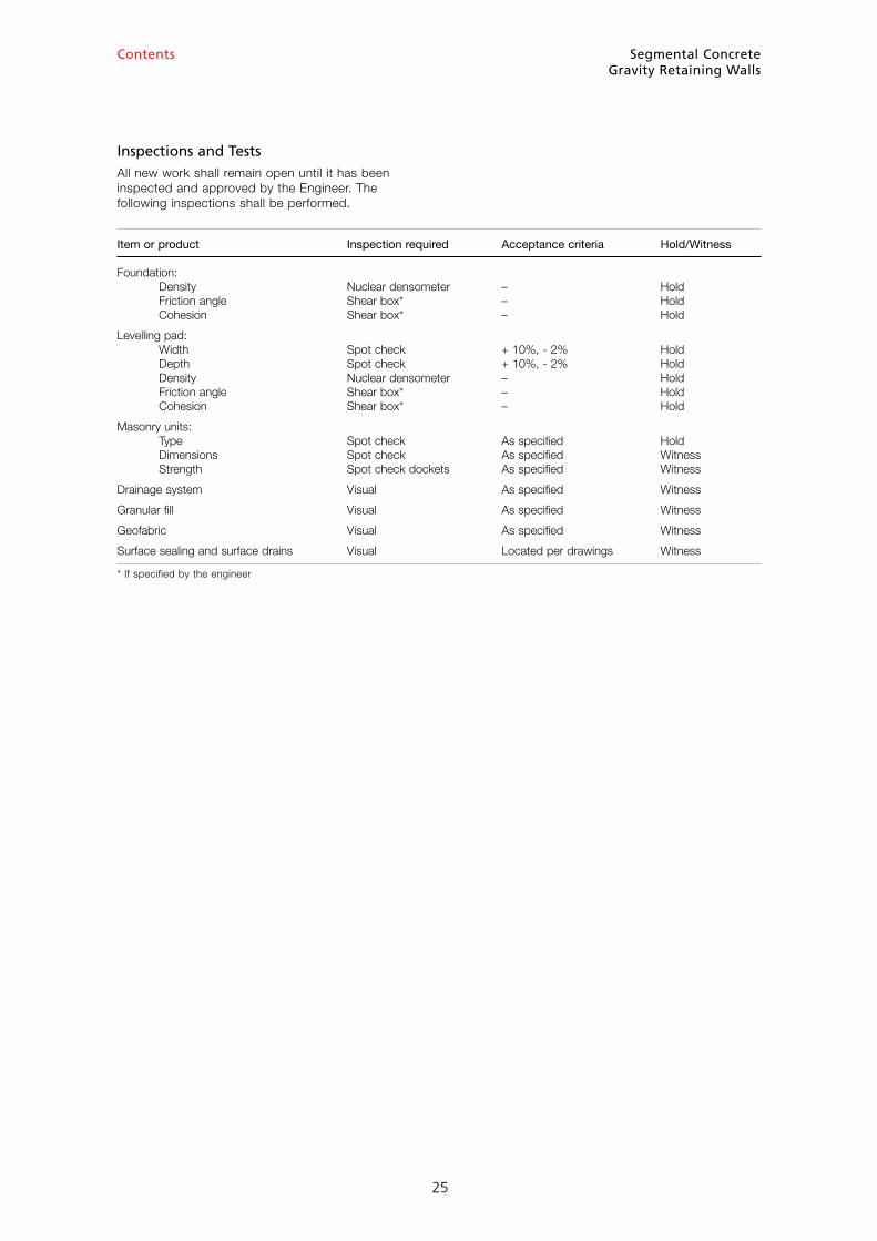
Inspections and TestsAll new work shall remain open until it has been inspected and approved by the Engineer. The following inspections shall be performed.
25
Item or product Inspection required Acceptance criteria Hold/Witness
Foundation: Density Nuclear densometer – Hold Friction angle Shear box* – Hold Cohesion Shear box* – Hold
Levelling pad: Width Spot check + 10%, - 2% Hold Depth Spot check + 10%, - 2% Hold Density Nuclear densometer – Hold Friction angle Shear box* – Hold Cohesion Shear box* – Hold
Masonry units: Type Spot check As specified Hold Dimensions Spot check As specified Witness Strength Spot check dockets As specified Witness
Drainage system Visual As specified Witness
Granular fill Visual As specified Witness
Geofabric Visual As specified Witness
Surface sealing and surface drains Visual Located per drawings Witness
* If specified by the engineer
Segmental ConcreteGravity Retaining Walls
26
Contents
Appendix D Height Table for Walls 800 to 1200 mm High
The Table may be used to determine the permissible height of retaining walls satisfying the following criteria. For retaining walls outside these criteria, the design shall be determined using engineering analysis similar to that shown in the worked example, Appendix A.
This Table is intended for use only by qualified and experienced civil or structural engineers with a comprehensive working knowledge of soil mechanics and structural analysis and design.
The limits of application of the Design Table are as follows:■ All retaining walls are designed to AS 4678
(Including Amendment 1).■ All retaining walls shall comply with AS 4678
Structure Classification A.■ Heights shall be within the range 800 mm to
1200 mm.■ All retaining walls are designed for level backfill.
If the backfill has a slope greater than 1 in 8, this Table will not be applicable.
■ This Table is only applicable to retaining walls that incorporate an impermeable surface membrane and drainage system such that there can be no ingress of any water into the soil behind the retaining wall.
■ Structures that do not incorporate an impermeable surface membrane and drainage system such that there can be no ingress of any water into the soil behind the retaining wall are deemed to be outside the scope of this Table.
■ Retained soil shall have a Plasticity Index, PI, less than 20.
■ The Table is applicable to cuts in insitu soils. The Table is not applicable to cohesive fill.
■ The Table applies to concrete retaining wall units of depth 280, 300 and 320 mm and a combined density of block and granular fill of 1860 kg/m3 or more.
■ All retaining walls are designed for an imposed load of 2.5 kPa. If imposed loads greater than 2.5 kPa are expected, these designs will not be appropriate.
■ This Table is based on 0.8 factor on the vertical component of soil friction, for both permanent and imposed soil and surcharge loads.
■ The Table applies only where footings consist of at least 5% cement-stabilised crushed rock with a minimum width of 600 mm and minimum depth of 150 mm.
■ Before the bottom course is positioned, the footing should be moistened to ensure bond between the block and footing.
■ The Table is based on the assumption that, within the above-mentioned limits, the active pressure coefficients, Ka, calculated using the Rankine–Bell Method are conservative for sloping walls.
■ Heights in the Table are derived using the Rankine–Bell Method assuming no water in the tension cracks.
■ 6 in the Table means that the permissible height is under 800 mm. Structure Classification A retaining structures under 800 mm high are outside the scope of AS 4678 and reference should be made to Appendix E.
■ Commercially-available segmental concrete retaining wall units may vary in mass, shape and dimensions from those shown in the Table. This will result in some variation in the permissible heights.
■ Interpolation of the tabulated heights is permissible.■ The Table is only applicable for cohesions and
internal friction angles tabulated. Extrapolation is not permitted.
Segmental ConcreteGravity Retaining Walls
27
Contents
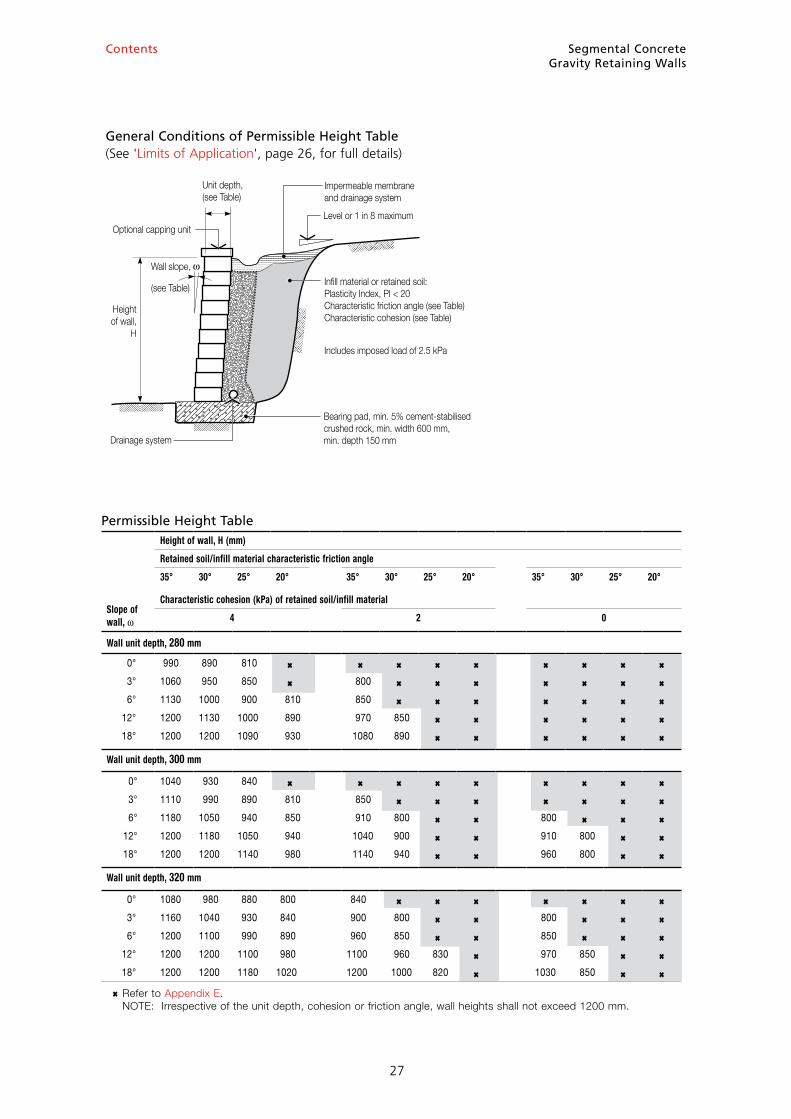
General Conditions of Permissible Height Table (See 'Limits of Application', page 26, for full details)
Drainage system
Infill material or retained soil:Plasticity Index, PI < 20Characteristic friction angle (see Table)Characteristic cohesion (see Table)
Includes imposed load of 2.5 kPa
Bearing pad, min. 5% cement-stabilisedcrushed rock, min. width 600 mm,min. depth 150 mm
Impermeable membraneand drainage system
Level or 1 in 8 maximumOptional capping unit
Unit depth,(see Table)
Heightof wall,
H
Wall slope,
(see Table)
Permissible Height Table
Slope ofwall, ω
Height of wall, H (mm)
Retained soil/infill material characteristic friction angle
35° 30° 25° 20° 35° 30° 25° 20° 35° 30° 25° 20°
Characteristic cohesion (kPa) of retained soil/infill material
4 2 0
Wall unit depth, 280 mm
0° 990 890 810 6 6 6 6 6 6 6 6 6
3° 1060 950 850 6 800 6 6 6 6 6 6 6
6° 1130 1000 900 810 850 6 6 6 6 6 6 6
12° 1200 1130 1000 890 970 850 6 6 6 6 6 6
18° 1200 1200 1090 930 1080 890 6 6 6 6 6 6
Wall unit depth, 300 mm
0° 1040 930 840 6 6 6 6 6 6 6 6 6
3° 1110 990 890 810 850 6 6 6 6 6 6 6
6° 1180 1050 940 850 910 800 6 6 800 6 6 6
12° 1200 1180 1050 940 1040 900 6 6 910 800 6 6
18° 1200 1200 1140 980 1140 940 6 6 960 800 6 6
Wall unit depth, 320 mm
0° 1080 980 880 800 840 6 6 6 6 6 6 6
3° 1160 1040 930 840 900 800 6 6 800 6 6 6
6° 1200 1100 990 890 960 850 6 6 850 6 6 6
12° 1200 1200 1100 980 1100 960 830 6 970 850 6 6
18° 1200 1200 1180 1020 1200 1000 820 6 1030 850 6 6
6 Refer to Appendix E. NOTE: Irrespective of the unit depth, cohesion or friction angle, wall heights shall not exceed 1200 mm.
Segmental ConcreteGravity Retaining Walls
28
Contents
Appendix E Details for Walls up to 800 mm high
This appendix may be used to determine the permissible height of retaining walls satisfying the following criteria. For retaining walls outside these criteria, the design shall be determined using engineering analysis similar to that shown in the worked example, Appendix A, by qualified and experienced civil or structural engineers with a comprehensive working knowledge of soil mechanics and structural analysis and design.
The limits of application of this Appendix are as follows:■ All retaining walls shall comply with the conditions
of Structure Classification A of AS 4678.■ Heights, excluding any capping blocks, shall not
exceed 800 mm.■ All retaining walls are designed for level backfill.
If the backfill has a slope greater than 1 in 8, this Appendix will not be applicable.
■ This Appendix does not apply to terraced retaining walls.
■ This Appendix is not suitable for imposed loads. If imposed loads are expected, the retaining wall should be designed by engineering analysis similar to that in the worked example, Appendix A.
■ This Appendix is not suitable for situations of excessive water run-off.
■ This Appendix applies to retaining walls with a compacted levelling pad.
■ This Appendix applies to concrete units of depth not less than 125 mm, with an interlocking mechanism and a combined density of block and granular fill of 1860 kg/m3 or more.
Structure Classification A retaining structures under 800 mm high are outside the scope of AS 4678.
Based on industry experience, the following ratios have been adopted.
Slope of wall, ω Wall height to block depth ratio, H:D
Vertical to 10° 3:1
Over 10° 4:1
Typical Wall Detail
Drainage system
Compacted levelling pad
Topsoil
Level or 1 in 8 maximum
Drainage material(eg blue metal)
Optional capping unit
Block depth,D
Heightof wall,
HWallslope

Intern
Textbox
PO Box 370, Artarmon NSW 1570 Australia Suite 3.02, Level 3, 44 Hampden Road Artarmon NSW 2064 Australia Telephone +61 2 8448 5500 Fax +61 2 9411 3801 ABN 33 065 618 804 ISBN 0 909407 52 5 www.cmaa.com.au