DESIGN OF PRACTICAL DESIGN AND TESTING FOR...
94
1 Jazan University College of Engineering Electrical Engineering Department DESIGN OF PRACTICAL DESIGN AND TESTING FOR DRIVE CIRCUIT OF MACHINE USING PULSE WIDTH MODULATION ( P.W.M ) By Team Members 1-Nabeel Eshwy 2- Yazead Otaif 3-Shreef Abu AL-Noor 4- Abdullah Kareri 5-Motab AL-Dawsari 6- Ibrahim Osayli 7-Sultan Asiri 8-Tariq AL-Qesi 9-Saeed AL-Taledi 10-Jaber AL-Ma Supervisor (s): Dr. Ahmed Oshaba ريخ التقدم تا( مايو/ 2014 )
Transcript of DESIGN OF PRACTICAL DESIGN AND TESTING FOR...

1
Jazan University
College of Engineering
Electrical Engineering Department
DESIGN OF PRACTICAL DESIGN AND
TESTING FOR DRIVE CIRCUIT OF
MACHINE USING PULSE WIDTH
MODULATION ( P.W.M )
By
Team Members
1-Nabeel Eshwy 2- Yazead Otaif
3-Shreef Abu AL-Noor 4- Abdullah Kareri
5-Motab AL-Dawsari 6- Ibrahim Osayli
7-Sultan Asiri 8-Tariq AL-Qesi
9-Saeed AL-Taledi 10-Jaber AL-Ma
Supervisor (s): Dr. Ahmed Oshaba
(2014/ مايو )تاريخ التقدم

2
Jazan University
College of Engineering
Electrical Engineering Department
PRACTICAL DESIGN AND TESTING FOR DRIVE
CIRCUIT OF MACHINE USING PULSE WIDTH
MODULATION ( P.W.M )
APPROVAL RECOMMENDED
EXAMINATION COMMITTEE : Dr. Shaban Eladl
Dr. Emad Said
Dr. Ehab Salm
Dr. Ahmed Oshaba
PROJECT SUPERVISORS : Dr. Ahmed Oshaba
DATE : _______________________________
DEPARTMENT HEAD : Dr. Ziad Tawfiq
DATE : _______________________________
APPROVED:
DEAN, COLLEGE OF ENGINEERING :
Dr.Mohammed Nour Bin Nahir Al-Maghrabi
DATE : _______________________________

3
DEDICATION
To our Fathers, who through their financial and moral support were the
source of inspiration and the mainstay in our attaining an education, we
dedicate this project.
ACKNOWLEDGEMENT
This project was written under the direction and supervision of Dr.
Ahmed Oshaba , We would like to express our sincere appreciation to him
for the interest and assistance given to us.

4
CONTENTS
4 DEDICATION 5 ACKNOWLEDGEMEN 6 CONTENTS
CHAPTER (1)
8 INTRODUCTION 9 1. Introduction 10 2. The Development of Power Converters
CHAPTER (2)
12 Classification of Electric Motors 13 1.Main Types of Motor
15 2.Types of DC motors 21 3. Types of AC motors 24 4. Speed Control of DC Series Motor
CHAPTER (3)
26 CONTROL OF THE ELECTRICAL MACHINES 27 1. Introduction 27 2. Type of DC Motor Control 27 3. Functions of DC Motor Control 28 4. Advantages of DC Motor 28 5. Disadvantages of DC Motor 28 6. Applications of DC Motors 29 7. Introduction to Electronic DC Drives 30 8. Electronic DC Drives: Control Methodology and characteristics
CHAPTER (4)
PAGE 31 CONVERTER 32 1. Introduction 32 2. Operation of Converter 33 3. Applications of Converter 33 4. DAC types 34 5. ADC types 35 6. DC to DC Converter
36 7. Types of DC to DC Converter
38 8. Basic Types of Inverters
CHAPTER (5)
.42 SIMULATION FOR DC MOTOR SYSTEM DRIVE BY USING
P.W.M CONVERTER

5
43 1. Introduction
43 2. Converter Simulation by Using Mat lab Simulink
43 3. Simulation of DC-DC Converter
47 4. Simulation of AC Inverter
48 5. Simulation of DC Motor is supplied by DC - DC Converter
CHAPTER (6)
53 PRACTICAL DESIGN, TESTING AND EXPERIMENTAL ORKS
54 1. Introduction
54 2. Drive Circuit of IGBT
Chapter (7)
90 CONCLUSION
91 A-REFERENCES
92 B-CAPSTONE DESIGN PROJECT C-APPENDICES
95 B-1: List of components
96 B-2: Integrated Circuits IC's datasheet

6
CHAPTER 1
INTRODUCTION

7
INTRODUCTION
Introduction
This project is mainly concerned on DC motor speed control system by designing a drive circuit.
It is an open-loop real time control system; pulse width modulation (PWM) technique is used
where its signal is generated by the drive circuit.
The PWM signal will send to motor drive to vary the voltage supply to motor to maintain at
required speed.
A typical electric drive system includes a controller, a transmission, an electric motor and a
driven load (e.g., fans, pumps, conveyors and others previously cited.) A key difference in
different types of electric drive systems is the type of controller: (A) distinct DC motor
control components, such as motor starters, switches and operator controls, or (B) electronic
motor controllers, called drive controls, which use semiconductors with electronic circuitry and
software to perform the same functions of distinct DC motor control components.
Fig. 1.1: System block diagram.
2. The Development of Power Converters
The heart of a switch-mode power supply (SMPS) is a DC-DC converter, which accepts a DC
input and produces a controlled DC output. Semiconductor DC-DC converters have appeared in
practical use since the 1960s. The three basic types of power converters are the buck, the boost,
and the buck-boost converters. The buck converter can work as step-down converter, while the
boost converter can work as step-up converter, and the buck-boost converter is working as step-
up step-down. The circuits of which are shown in Fig. 1-2.

8
(a) Buck converter
(b) Boost Converter
(C) Buck-Boost Converter
Fig. 1.2: Basic square-wave converters.
In 1977, CûK and Middlebrook introduced a new "optimum topology switching DC toDC
converter", which is now more commonly referred to as the CûK converter. Fig. 1-3 shows
the basic circuit of the CûK converter, which functionally is a cascaded connection of a
boost converter followed by a buck converter. Consequently, it works as step-up step-down
converter. Various topologies of square wave converters were also studied by CûK , and
Landsman . Recently: much attention has been focused on the design of high frequency
converters with reduced weight and size , and the use of fast MOS or IGBT power
transistors as switching elements .
Dfw

9
Fig. 1.3 CûK Converter.
Since power converters and the SMPS are nonlinear circuits, computer aided analysis and
design techniques for such circuits are highly desirable.
In the next chapter we will discuss each type of those converters.

10
CHAPTER 2
Classification of Electric Motors

11
Classification of Electric Motors
Main Types of Motor:
Electric motors are broadly classified into two categories as follows:
1. AC Motors.
2. DC Motors.

12
First: DC motors
Fig.2: DC motor section
DC motors have been used in industrial applications for years Coupled with a DC drive, DC
motors provide very precise control DC motors can be used with conveyors, elevators,
extruders, marine applications, material handling, paper, plastics, rubber, steel, and textile
applications, automobile, aircraft, and portable electronics, in speed control applications.
Advantages of DC motors:
It is easy to control their speed in a wide range; their torque-speed characteristic has, historically,
been easier to tailor than that of all AC motor categories.
Their reduced overall dimensions permit a considerable space saving which let the manufacturer
of the machines or of plants not to be conditioned by the exaggerated dimensions of circular
motors.
Disadvantages of DC motors
Brush wear occurs, and it increases dramatically in low‐ pressure environment.
Sparks from the brushes may cause explosion if the environment contains explosive materials.
RF noise from the brushes may interfere with nearby TV sets, or electronic devices, Etc.
DC motors are also expensive relative to AC motors.
Thus all application of DC motors have employed a mechanical switch or commutator to turn the
terminal current, which is constant or DC, into alternating current in the armature of the machine.
Therefore, DC machines are also called commutating machines.
All application of DC motors have employed a mechanical switch or commutator to turn the terminal
current, which is constant or DC, into alternating current in the armature of the machine.

13
Types of DC motors:
The DC motors are divided to:
1. Brush DC motors (BDC).
2. Brushless DC motors (BLDC).
1 : Brush DC motors:
Fig.2: brushed DC motor
A brushed DC motor (BDC) is an internally commutated electric motor designed to be run from a direct current
power source.

14
Applications:
Brushed DC motors are widely used in applications ranging from toys to push-button
adjustable car seats.
Advantages:
Brushed DC (BDC) motors are inexpensive, easy to drive, and are readily available in all
sizes and shapes
Disadvantages:
Brushes wear and create an eclectically conductive dust
Electrical noise (EMI & RFI Interference) from the brush commutator interface
Commutator wear
Cogs at low speed
Construction:
1. Stator
The stator generates a stationary magnetic field that surrounds the rotor. This field is generated
by either permanent magnets or electromagnetic winding.
2. Rotor
The rotor is made up of one or more windings. When these windings are energized they produce
a magnetic field. The magnetic poles of this rotor field will be attracted to the opposite poles
generated by the stator, causing the rotor to turn. As the motor turns, the windings are constantly
being energized in a different sequence so that the magnetic poles generated by the rotor do not

15
overrun the poles generated in the stator. This switching of the field in the rotor windings is
called commutation.
3. Brushes and Commutator:
The commutation of the windings of a BDC motor is done mechanically. A segmented copper
sleeve, called a commutator, resides on the axle of a BDC motor. As the motor turns, carbon
brushes (ride on the side of the commutator to provide supply voltage to the motor) slide over
the commutator, coming in contact with different segments of the commutator.
Types of BDC motors:
The different types of BDC motors are distinguished by the construction of the stator or the way
the electromagnetic windings are connected to the power source. These types are:
1. Permanent Magnet
2. Shunt-Wound
3. Series-Wound
4. Compound-Wound
5. Separately excited DC motor
6. Universal Motor

16
7. Servo Motors
1-Permanent Magnet:
A permanent magnet DC (PMDC) motor is a motor whose poles are made out of permanent
magnets to produce the stator field.
Advantages:
Since no external field circuit is needed, there are no field circuit copper losses.
Since no field windings are needed, these motors can be considerable smaller .
Widely used in low power application.
Field winding is replaced by a permanent magnet (simple construction and less space).
No requirement on external excitation
Disadvantages:
Since permanent magnets produces weaker flux densities then externally supported shunt
fields, such motors have lower induced torque .
There is always a risk of demagnetization from extensive heating or from armature
reaction effects (Some PMDC motors have windings built into them to prevent this from
happening).
2- Shunt-Wound:
Shunt-wound Brushed DC (SHWDC) motors have the field coil in parallel (shunt) with the
armature .
The speed is practically constant independent of the load and therefore suitable for commercial
applications with a low starting load, such as centrifugal pump, machine tools, blowers fans,
reciprocating pumps, etc

17
Advantages:
1. The current in the field coil and the armature are independent of one another. As a result,
these motors have excellent speed control
2. Loss of magnetism is not an issue in SHWDC motors so they are generally more robust
than PMDC motors
3. Speed can be controlled by either inserting a resistance in series with the armature
(decreasing speed) or by inserting resistance in the field current (increasing speed)
Disadvantages:
1. It has drawbacks in reversing applications, however, because winding direction relative
to the shunt winding must be reversed when armature voltage is reversed. Here,
reversing contactors must be used
3- Series-Wound:
These motors are ideally suited for high-torque applications such as traction vehicles (cranes and
hoists, electric trains, conveyors, elevators, electric cars) because the current in both the stator
and armature increases under load
Advantages:
The torque is proportional to I2 so it gives the highest torque per current ratio over all
other DC motors.

18
Disadvantages:
A drawback to SWDC motors is that they do not have precise speed control like PMDC
and SHWDC motors have.
Speed is restricted to 5000 RPM.
It must be avoided to run a series motor with no load because the motor will accelerate
uncontrollably.
4- Compound-Wound:
Compound Wound (CWDC) motors are a combination of shunt-wound and series-wound
motors.
CWDC motors employ both a series and a shunt field. The performance of a CWDC motor is a
combination of SWDC and SHWDC motors. CWDC motors have higher torque than a SHWDC
motor while offering better speed control than SWDC motor.
It is used in Applications such as Rolling mills, sudden temporary loads, heavy machine tools,
punches, etc.
:
Advantages:
This motor has a good starting torque and a stable speed.
Disadvantages:
The no-load speed is controllable unlike in series motors.
5- Separately excited DC motor:
In a separately excited DC motor the field coils are supplied from an independent source, such
as a motor-generator and the field current is unaffected by changes in the armature current. The

19
separately excited DC motor was sometimes used in DC traction motors to facilitate control of
wheel slip.
Advantages:
Cost savings.
Additional cost savings from using a single DC controller instead of two AC controllers;
Elimination of the steering and motor-speed sensors;
Lower DC motor cost;
Simplified and less expensive wiring; and
Better performance.
6- Universal Motor:
The universal motor is a rotating electrical machine similar to DC series motor, designed to
operate either from AD or DC source. The stator & rotor windings of the motor are connected in
series through the rotor commutator. The series motor is designed to move large loads with high
torque in applications such as crane motor or lift hoist.
Advantages:

20
Small size, operates at 7,500 to 10,000 rpm
Lighter weight per HP rating
Can operate on AC or DC
Ideal for hand held tools
Ideal for home appliances like vacuum cleaners
Low cost
High starting torque
Disadvantages:
Operates at 7,500 to 10,000 rpm
Requires gearing to reduce the output speed but gains output torque (adds to the audible
noise)
Brushes, less reliable
Noisy
Unidirectional
Poor speed regulation
7- Servo Motors:
Servo Motors are mechanical devices that can be instructed to move the output shaft attached to
a servo wheel or arm to a specified position. Servo Motors are designed for applications
involving position control, velocity control and torque control.
A servo motor mainly consists of a DC motor, gear system, a position sensor which is mostly a
potentiometer, and control electronics
.
Advantages:
Intermediate motor and control costs
Continuous duty
21
Reversible.
Speed is proportional to the applied voltage
Torque is proportional to the current
Very efficient
No power required to hold a static load in position
Flat speed-torque curve
Peak torque available for short periods of time
Smooth rotation at low speeds
Good up to 3,000 RPM
Disadvantages:
Brushes wear and create an eclectically conductive dust
Electrical noise (EMI & RFI Interference) from the brush commutator interface
Commutator wear
Position is limited to the feedback resolution (2000 line encoder produces 8000 steps per
revolution
Poor thermal performance. Current/heat is in the rotor.
Requires tuning
Second- AC Motors:
The basic parts for AC motors are as follows:
1. Enclosure.
2. Stator.
3. Rotor.
4. Bearings.

22
5. Conduit Box.
6. Eye Bolt.
1- Enclosure:
The enclosure consists of a frame (or yoke) and two end brackets (or bearing housings).
A motor's enclosure not only holds the motor's components together, it also protects the internal
components from moisture and containments. The degree of protection depends on the enclosure
type. In addition, the type of enclosure affects the motor's cooling.
2- Stator:
The motor stator consists of two main parts:
A- Stator Core :
The stator is the stationary part of the motor's electromagnetic circuit. The stator is electrical
circuit that performs as electromagnet. The stator core is made up of many thin metal sheets,
called laminations.
B- Stator (Windings)

23
Stator laminations are stacked together forming a hollow cylinder. Coils of insulated wire are
inserted into slots of the stator core.
3- Rotor:
The rotor is the rotating part of the motor's electromagnetic circuit. Magnetic field from the
stator induces an opposing magnetic field onto the rotor causing the rotor to “push” away from
the stator field.
There are a lot of rotor types like Squirrel cage rotor and wound rotor.
4- Bearings:
Bearings, mounted on the shaft, support the rotor and allow it to turn. Not all bearings are
suitable for every application; a universal, all-purpose bearing does not exist.
The size of the bearing to be used is initially selected on the basis of its load carrying capacity,
in relation to the load to be carried, and the requirements regarding its life and reliability.
Types of AC motors:
An AC motor is an electric motor driven by an alternating current (AC).

24
It commonly consists of two basic parts, an outside stationary stator having coils supplied with
alternating current to produce a rotating magnetic field, and an inside rotor attached to the output
shaft that is given a torque by the rotating field.
There are two main types of AC motors, depending on the type of rotor used. The first type is
the induction motor or asynchronous motor;
First-Induction motor:
Three Phase Induction Motor:
The three phase ac induction motor is also called a squirrel cage motor. Both single phase and
three phase motors operate on the principle of a rotating magnetic field. A horseshoe magnet
held over a compass needle is a simple illustration of the principle of the rotating field.
Advantages:
High starting and running torque
Relatively constant speed
Fast acceleration
Brushless, more reliable
Economical
Size ranges from about 1/10 to about 10 HP
Disadvantages:
Can’t be used with a speed control
Low start and stop rate
High starting current
Prolonged starting time can cause over heating
Has a mechanical centrifugal switch
Second-Synchronous Motor:
The synchronous motor makes use of a rotating magnetic field. Unlike the induction motor,
however, the torque developed does not depend on the induction of currents in the rotor. Briefly,
the principle of operation of the synchronous motor is as follows: A multiphase source of ac is
applied to the stator windings, and a rotating magnetic field is produced.

25
A direct current is applied to the rotor winding, and another magnetic field is produced.
Advantages:
Operates at an exact, constant speed
Brushless, more reliable
Disadvantages:
Low starting torque
Starting the load inertia must be within the motor’s capability.
Speed Control of DC Motor:
Speed control means intentional change of the drive speed to a value required for performing the
specific work process. Speed control is a different concept from speed regulation where there is
natural change in speed due change in load on the shaft.
Speed of the DC machine can be controlled by:
1. By applying the voltage to the terminals of the dc machine
2. By introducing external resistance in the armature of the machine
3. By varying the flux per pole (φ) of the machine
Speed Control of DC Series Motor:
Speed control of DC series motor can be done either by armature control or by field control.
First: Armature Control of DC Series Motor:
Speed adjustment of DC series motor by armature control may be done by any one of the
methods that follow,

26
i) Armature Resistance Control Method: In armature resistance control method a
variable resistance is connected in series to the armature circuit. When the resistance of
the rheostat is increased, current flowing through the circuit reduces and the voltage drop
at the armature is less compared to line voltage. Thus speed of the machine reduces in
proportional to the applied voltage.
ii) Shunt Resistance Control Method: In this method the change in the armature current
(because of the load torque) does not affect the change in the voltage across the terminals
hence the speed.
iii) Armature Voltage Control: In this method of speed control a variable source of voltage
is provided to supply the power to the armature circuit. Voltage to the field circuit should
be different from the variable voltage source provided to the armature.
Second: Field Control Method of speed control:
The speed can be controlled by:
Providing a variable resistance in series to the field circuit so that variation in the
resistance value results in increase or decrease in the field of the machine resulting in the
speed control.
By variation in the reluctance of the magnetic circuit of the motor.
By varying the applied voltage to the field circuit of the DC motor by keeping the
voltage supplied to the armature circuit constant.
i) Field Resistance Control: In this method variable resistance is employed in series to the
field circuit. As in this method when resistance value increases only field weakens.
By weakening the field speed above the normal speed can be attained.
ii) Reluctance Control Method: This method requires motor to be constructed with special
mechanical features such that reluctance of the magnetic circuit can be changed. This
is more expensive and rarely employed.
iii) Filed Voltage Control: This method requires variable voltage source which is different
from the voltage applied to the armature circuit.

27
Chapter 3
CONTROL OF THE
ELECTRICAL MACHINES

28
CONTROL OF THE ELECTRICAL MACHINES
1. Introducton
A typical electric drive system includes a controller, a transmission, an electric motor and a
driven load (e.g., fans, pumps, conveyors and others previously cited.) A key difference in
different types of electric drive systems is the type of controller: (A) distinct DC motor
control components, such as motor starters, switches and operator controls, or (B) electronic
motor controllers, called drive controls, which use semiconductors with electronic circuitry and
software to perform the same functions of distinct DC motor control components.
2. Types of DC Motor Control
There are three general types of DC motor control: manual, semi-automatic and automatic.
Manual control directly connects a DC motor to the input power line or mains. Operator
intervention is required. Semi-automatic control uses switches or sensors (.e.g., limit, pressure,
temperature, float level, flow, proximity, timing and photo-sensitive switches) to control a
magnetic contactor or starter which, when enabled or closed, will connect the motor to the input
power line. In semi-automatic operation, an operator is needed to start or stop the motor but the
rest of the operation is controlled by the sensors or switches. Automatic control is similar to
semi-automatic control with one important difference: no operator intervention is required. For
example, a thermostat in an air conditioning system or a refrigerator will turn a compressor
motor on or off to maintain the set point temperature automatically.
3. Functions of DC Motor Control
Whether a DC motor is controlled manually, semi-automatically or automatically, the control
system will perform a variety of common functions, which include:
Starting
Stopping
Jogging/Inching
Plugging
Speed Control
Reversing
Braking
Protection

29
4. Advantages of DC Motors
Ease of control
Deliver high starting torque
Near-linear performance
5. Disadvantages of DC Motors
High maintenance
Large and expensive (compared to induction motor)
Not suitable for high-speed operation due to commutator and brushes
Not suitable in explosive or very clean environment
An applications of DC Motors doesn't indicate the use only, it means why and where we use
a DC Motor. As we all know DC Motors are of three types: -
Shunt Motors
Series Motors
Compound Motors
I will not go in deep about the classification. For those who are not aware about the
classification I would like to tell why this name is given ?
The name for a DC Motor is given on the bases of connection between armature and field
coil. If field coil or field winding is connected in parallel with the armature then the motor is
called shunt motor, if connection is series the motor is called series motor and if two field
windings are used one is series and one in shunt then the motor is called compound motor.
6. Applications of DC Motors
Now I will discuss application criteria for all three types of DC Motors.
6.1. Shunt Motors
There are three kind of characteristics for a motor viz. Speed-Torque, Speed-Current and
Torque-Current characteristics. After analyzing all three characteristics for DC Shunt Motor it is
observed that it is an approximately constant speed motor. It is therefore, used where the speed
is required to remain almost constant from no-load condition to full load-condition.
The load has to be driven at a number of prefer and any one of which is required to remain
nearly constant.
Industrial Use: - Lathes, Drills, Boring Mills, Shapers, Spinning and Weaving Machines etc.

30
6.2. Series Motors
After analyzing all three characteristics for DC Series Motor it is observed that it is a variable
speed motor. It means speed it low at high torque and vice-versa. However, at light or no-load,
the motor tends to attain dangerously high speed. The motor has a high starting torque. It is
therefore, used where Large starting torque is required like in Elevators and Electric Traction.
The load is subjected to heavy fluctuations and the speed is automatically required on sewing
machines etc.
Industrial Use : - Electric traction, brands, elevators, air compressors, vacuum cleaners, hair
drier, sewing machines etc.
6.3. Compound Motors
DC Compound Motor is of two types. It is therefore, used where, specification required for
particular motor. Differential-compound motors are rarely used because of their poor torque
characteristics. Cumulative-compound motors are used where a fairly constant speed is required
with irregular loads or suddenly applied heavy load.
7. Introduction to Electronic DC Drives
An electronic DC drive, sometimes called a semi-conductor drive, is a subset of all the
various electric drive systems used to control the motion and vary the speed of a DC motor.
Early electric drive types, such as the Ward-Leonard system, controlled the motors indirectly.
The Ward-Leonard system is an AC motor-DC generator set that feeds a variable voltage to the
armature of a shunt wound DC motor to vary the motor’s speed. While the Ward-Leonard
system has good speed and torque control with a speed range of 25:1, it was phased out due to
the excessive cost of purchasing three separate rotating machines as well as the considerable
maintenance necessary to keep the brushes and commutators of two DC machines in proper
operating conditions. (A similar fate happened to the eddy current clutch. )
Today’s electronic DC drives have numerous advantages over previous electrical drive
systems, such as the Ward-Leonard drive. They include:
Large range of power availability.
Capable of full torque at standstill without a clutch.
Very large speed range without needing gearboxes.
Clean operation.
Safe operation in hazardous environments.
Immediate use (no warm up time)
Low no-load losses.

31
Low acoustic noise.
Excellent control ability.
Four-quadrant operation: forward motoring, forward braking, reverse motoring and
reverse braking
.
While the advantages are numerous, electronic DC drives have some disadvantages, such as:
Very complex and require highly skilled technicians to maintain.
Introduce harmonics/electrical noise into the power line
8. Electronic DC Drives: Control Methodology and Characteristics
An electronic DC drive is an electronic thyristor AC/DC converter/rectifier or a DC/DC
converter, called a DC chopper. A converter is a complex electronic control that can precisely
control a DC motor’s rotation, torque and speed characteristics. AC/DC converters come in
several configurations: (A) full-wave, 12-pulse bridge, (B) full-wave, 6-pulse bridge, or (C)
half-wave, 3-pulse bridge. The most common configuration is the full-wave, 6-pulse bridge
because it produces less distortion on the DC side of the converter and has lower losses in the
DC motor than a 3-pulse bridge. (12-pulse bridges are typically used on larger drives to reduce
harmonics on the AC power line.) The efficiency of the converter is usually greater than 98%
and the overall efficiency of the DC drive plus the DC motor is about 90%. In addition, AC/DC
converters can be built for applications up to several megawatts with good control and
performance characteristics.
The other type of DC drive controller is a DC-to-DC converter or a DC chopper. While an
AC/DC converter is powered from an A.C. supply, the DC chopper is powered from a DC
power source. Both electronic controls produce a variable DC voltage that when applied to the
DC motor’s armature varies the armature current, hence, the motor speed. The AC/DC converter
produces this variable DC voltage by controlling the firing angle of its SCR bridge rectifier,
while a DC chopper varies the voltage by controlling the varying angle to vary the duty
cycle. The output voltage of the chopper is in the form of pulses. The time ratio of the chopper
can be controlled to vary the average voltage. Voltage variation at the load can be obtained by
either current limit or time ratio control. For instance, in current-limit control, when current
reaches the upper limit, the chopper is turned off to disconnect the motor from supply. Load
current freewheels through the freewheeling diode and decays. When it falls to the lower limit,
the chopper is turned on and connected to supply, thus, an average current is maintained.

32
CHAPTER 4
Convertor

33
CONVERTERS
Introduction:
There are two basic types of converters, digital-to-analog and analog-to digital.
Their purpose is fairly straightforward. In the case of DACs ,they output an analog voltage that
is a proportion of a reference voltage, the proportion based on the digital word applied. In the
case of the ADC, a digital representation of the
analog voltage that is applied to the ADCs input is outputted, the representation
proportional to a reference voltage.
First: DIGITAL-TO-ANALOG CONVERTER:
A digital-to-analog converter (DAC or D-to-A) is a device that converts a digital (usually
binary) code to an analog signal (current, voltage, or electric charge). An analog-to-digital
converter (ADC) performs the reverse operation. Signals are easily stored and transmitted in
digital form, but a DAC is needed for the signal to be recognized by human senses or other non-
digital systems.
Operation:
Instead of impulses, usually the sequence of numbers update the analog voltage at uniform
sampling intervals which are often then interpolated via a reconstruction filter to continuously
varied levels.
These numbers are written to the DAC, typically with a clock signal that causes each number to
be latched in sequence, at which time the DAC output voltage changes rapidly from the previous
value to the value represented by the currently latched number. The effect of this is that the
output voltage is held in time at the current value until the next input number is latched resulting
in a piecewise constant or 'staircase' shaped output. This is equivalent to a zero-order hold
operation and has an effect on the frequency response of the reconstructed signal.

34
Piecewise constant output of an idealized DAC lacking a reconstruction filter.
Applications:
1. Audio:
Most modern audio signals are stored in digital form (for example MP3s and CDs) and in order
to be heard through speakers they must be converted into an analog signal.
A simplified functional diagram of an 8-bit DAC
2. Video:
Video sampling tends to work on a completely different scale altogether thanks to the highly
nonlinear response both of cathode ray tubes (for which the vast majority of digital video
foundation work was targeted) and the human eye, using a "gamma curve" to provide an
appearance of evenly distributed brightness steps across the display's full dynamic range.
Top-loading CD player and external digital-to-analog converter.
DAC types:
There are many types of DAC, like:
The pulse-width modulator, the simplest DAC type.
Oversampling DACs or interpolating DACs.
The binary-weighted DAC.

35
Pulse-width modulation (PWM):
PWM Is a modulation technique that conforms the width of the pulse, formally the pulse
duration, based on modulator signal information. Although this modulation technique can be
used to encode information for transmission, its main use is to allow the control of the power
supplied to electrical devices, especially to inertial loads such as motors. In addition, PWM is
one of the two principal algorithms used in photovoltaic solar battery chargers.
PWM in an AC motor drive.
The average value of voltage (and current) fed to the load is controlled by turning the switch
between supply and load on and off at a fast pace. The longer the switch is on compared to the
off periods, the higher the power supplied to the load is.
Applications:
1) Telecommunications:
In telecommunications, PWM is a form of signal modulation where the widths of the pulses
correspond to specific data values encoded at one end and decoded at the other.
Pulses of various lengths (the information itself) will be sent at regular intervals (the carrier
frequency of the modulation).
2) Power delivery:
PWM can be used to control the amount of power delivered to a load without incurring the
losses that would result from linear power delivery by resistive means. Potential drawbacks to
this technique are the pulsations defined by the duty cycle, switching frequency and properties
of the load. With a sufficiently high switching frequency and, when necessary, using additional
passive electronic filters, the pulse train can be smoothed and average analog waveform
recovered.
3) Voltage regulation:
PWM is also used in efficient voltage regulators. By switching voltage to the load with the
appropriate duty cycle, the output will approximate a voltage at the desired level. The switching
noise is usually filtered with an inductor and a capacitor.
4) Audio effects and amplification:

36
PWM is sometimes used in sound synthesis, in particular subtractive synthesis, as it gives a
sound effect similar to chorus or slightly detuned oscillators played together. (In fact, PWM is
equivalent to the difference of two sawtooth waves with one of them inverted.
Second: ANALOG-TO-DIGITAL CONVERTER:
An analog-to-digital converter is a device that converts a continuous physical quantity (usually
voltage) to a digital number that represents the quantity's amplitude.
The conversion involves quantization of the input, so it necessarily introduces a small amount of
error. Instead of doing a single conversion, an ADC often performs the conversions ("samples"
the input) periodically. The result is a sequence of digital values that have converted a
continuous-time and continuous-amplitude analog signal to a discrete-time and discrete-
amplitude digital signal.
Photo of the ADC-16 Analog to Digital converter
ADC types:
1. Direct-conversion ADC or flash ADC.
2. Successive-approximation ADC.
3. Ramp-compare ADC.
4. The Wilkinson ADC.
5. An integrating ADC.
6. A time-stretch analog-to-digital converter (TS-ADC).
Applications:
1) Digital signal processing:
People must use ADCs to process, store, or transport virtually any analog signal in
digital form. TV tuner cards, for example, use fast video analog-to-digital converters.
Slow on-chip 8, 10, 12, or 16 bit analog-to-digital converters are common in

37
microcontrollers. Digital storage oscilloscopes need very fast analog-to-digital
converters, also crucial for software defined radio and their new applications.
2) Scientific instruments:
Digital imaging systems commonly use analog-to-digital converters in digitizing pixels.
Some radar systems commonly use analog-to-digital converters to convert signal
strength to digital values for subsequent signal processing. Many other in situ and remote
sensing systems commonly use analogous technology.
The number of binary bits in the resulting digitized numeric values reflects the
resolution, the number of unique discrete levels of quantization (signal processing).
DC to DC Converter:
This is a type of converter. DC-DC converters are electronic devices used to change DC
electrical power efficiently from one voltage level to another. They are needed because unlike
AC, DC cannot simply be stepped up or down using a transformer. In many ways, a DC-DC
converter is the DC equivalent of a transformer.
DC/DC Converter DC12V to 24V 2A by IC 40106 and Mosfet BUZ11
Applications:
DC to DC converters are important in portable electronic devices such as cellular phones and
laptop computers, which are supplied with power from batteries primarily. Such electronic
devices often contain several sub-circuits, each with its own voltage level requirement different
from that supplied by the battery or an external supply (sometimes higher or lower than the
supply voltage).

38
Conversion methods:
Electronic:
Linear regulators can only output at lower voltages from the input. They are very
inefficient when the voltage drop is large and the current is high as they dissipate heat
equal to the product of the output current and the voltage drop; consequently they are not
normally used for large-drop high-current applications.
A linear 5V regulator IC
Linear regulators are practical if the current is low, the power dissipated being small,
although it may still be a large fraction of the total power consumed. They are often used
as part of a simple regulated power supply for higher currents.
Switched-mode conversion:
It converts one DC voltage level to another, by storing the input energy temporarily and
then releasing that energy to the output at a different voltage.
Switched-mode power supply
Magnetic:
In these DC-to-DC converters, energy is periodically stored into and released from a
magnetic field in an inductor or a transformer, typically in the range from 300 kHz to 10
MHz. By adjusting the duty cycle of the charging voltage the amount of power
transferred can be controlled.

39
Types of DC to DC Converter:
1. Linear Voltage Converters:
The most elementary DC-DC converters are linear voltage converters. They achieve DC-
DC voltage conversion by dissipating the excess power into a resistor, making them
resistive dividers. The advantage of linear voltage converters is that they are fairly
simple to implement. Moreover, they generally do not need large, and space consuming,
inductors or capacitors, making them an attractive option for monolithic integration.
(a) The principle of a linear series voltage converter and (b) a simple practical
implementation
2. Buck Converters:
A buck converter (DC-DC) is a switch for which a device as described earlier belonging
to transistor family is used. Also a diode (termed as free wheeling)
is used to allow the load current to flow through it, when the switch (i.e., a device) is
turned off.
The load is inductive (R-L) one. In some cases, a battery (or back emf) is connected in
series with the load (inductive). Due to the load inductance, the load current must be
allowed a path, which is provided by the diode; otherwise, i.e., in the absence of
the above diode, the high induced emf of the inductance, as the load current tends to
decrease, may cause damage to the switching device.
Buck converter (DC-DC)

40
Output voltage and current waveforms
3. Boost Converters (DC-DC):
The operation of the circuit is explained. Firstly, the switch, S (i.e., the device) is put ON
(or turned ON) during the period, the ON period being . The output voltage is
zero , if no battery (back emf) is connected in series with the load, and also as stated
earlier, the load inductance is small. The current from the source (is ) flows in the
inductance L.
Boost converter (dc-dc)
Waveforms of source current
4. Current Limit Control:
the current changes between the maximum and minimum values, if it (current) is
continuous. In the current limit control strategy, the switch in DC-DC converter
(chopper) is turned ON and OFF, so that the current is maintained between two (upper
and lower) limits.

41
Current limit control
Basic Types of Inverters:
There are different types of inverters for home available which can suit your various electricity
needs. The availability of inverter service centers also make it easy for you to get them fixed.
Following are the two basic types of inverters.
1. Modified Sine Wave Inverters:
This type of home inverter obtains power from a battery of 12 volts and must be recharged using
a generator or a solar panel. Appliances like microwave ovens, light bulbs, etc. can be run using
these types of inverter.
They can be rightly held as the best inverters for homes as they are efficient enough to
provide power to the normal home requirement.
They are the home inverters that are most affordable too.
You can run the daily used home appliances using the modified sine wave home
inverters.
The electric appliances that involve motor speed controls or timers are not to be run
using these types of home inverters.

42
2. True Sine Wave Inverters:
This is one of the better types of inverters as they provide better power as compared to the
modified sine wave inverters for homes. These types of home inverter are also run using a
battery of a larger capacity.
Technically speaking, the sine waves they produce are purer, thus the efficiency.
They are best inverters employed for the power sensitive appliances like
refrigerators, televisions, air conditioners, washing machines, etc.
These types of inverters are extremely reliable. The only drawback is that they
are a bit expensive and cannot be afforded by the common man.
There are various models available based on the electricity requirement of the
house.
3. Solar Inverters:
A solar inverter, or PV inverter, converts the variable direct current (DC) output of a
photovoltaic (PV) solar panel into a utility frequency alternating current (AC) that can be fed
into a commercial electrical grid or used by a local, off-grid electrical network. It is a critical
component in a photovoltaic system, allowing the use of ordinary commercial appliances.
Some basic types of solar inverters are:
Stand-alone inverters:
Stand-alone inverter or off-grid inverter is designed for remote stand-alone application or
off-grid power system with battery backup where the inverter draws its DC power from
batteries charged by PV array and converts to AC power.

43
Grid connected inverter:
Grid connected inverter or grid tie inverter is designed specifically for grid connected
application that does not require battery backup system. Grid connected inverter or grid
tie inverter converts DC power produced by PV array to AC power to supply to electrical
appliances and sell excess power back to utility grid.
Hybrid inverter:
Hybrid inverter or hybrid power inverter is designed for hybrid power system that
combines solar array with diesel generator and other renewable energy sources such as
wind turbine generator, hydro generator, etc. Hybrid inverter can operate as either a
stand-alone inverter or a grid tie inverter.
4. Power inverter:
A power inverter, or inverter, is an electrical power converter that changes direct current (DC) to
alternating current (AC). The input voltage, output voltage, and frequency are dependent on
design.
Applications:
1. DC power source utilization:
An inverter converts the DC electricity from sources such as batteries, solar panels,
or fuel cells to AC electricity. The electricity can be at any required voltage; in
particular it can operate AC equipment designed for mains operation, or rectified to
produce DC at any desired voltage.
2. Uninterruptible power supplies:
An uninterruptible power supply (UPS) uses batteries and an inverter to supply AC
power when main power is not available. When main power is restored, a rectifier
supplies DC power to recharge the batteries.
3. Induction heating:
Inverters convert low frequency main AC power to higher frequency for use in
induction heating. To do this, AC power is first rectified to provide DC power. The
inverter then changes the DC power to high frequency AC power.
4. HVDC power transmission:
With HVDC power transmission, AC power is rectified and high voltage DC power
is transmitted to another location. At the receiving location, an inverter in a static
inverter plant converts the power back to AC. The inverter must be synchronized
with grid frequency and phase and minimize harmonic generation.
5. Variable-frequency drives:

44
A variable-frequency drive controls the operating speed of an AC motor by
controlling the frequency and voltage of the power supplied to the motor. An inverter
provides the controlled power. In most cases, the variable-frequency drive includes a
rectifier so that DC power for the inverter can be provided from main AC power.
6. Electric vehicle drives:
Adjustable speed motor control inverters are currently used to power the traction
motors in some electric and diesel-electric rail vehicles.
7. Air conditioning:
An inverter air conditioner uses a variable-frequency drive to control the speed of the
motor and thus the compressor.
Circuit description:
In one simple inverter circuit, DC power is connected to a transformer through the center
tap of the primary winding. A switch is rapidly switched back and forth to allow current
to flow back to the DC source following two alternate paths through one end of the
primary winding and then the other. The alternation of the direction of current in the
primary winding of the transformer produces alternating current (AC) in the secondary
circuit.
Output waveforms:

45
When not coupled to an output transformer, produces a square voltage waveform due to
its simple off and on nature as opposed to the sinusoidal waveform that is the usual
waveform of an AC power supply. Using Fourier analysis, periodic waveforms are
represented as the sum of an infinite series of sine waves. The sine wave that has the
same frequency as the original waveform is called the fundamental component. The
other sine waves, called harmonics, that are included in the series have frequencies that
are integral multiples of the fundamental frequency.
5. Controlled rectifier inverters:
The thyristor or silicon-controlled rectifier (SCR) that initiated the transition to solid state
inverter circuits.
The commutation requirements of SCRs are a key consideration in SCR circuit designs. SCRs
do not turn off or commutate automatically when the gate control signal is shut off. They only
turn off when the forward current is reduced to below the minimum holding current, which
varies with each kind of SCR, through some external process. For SCRs connected to an AC
power source, commutation occurs naturally every time the polarity of the source voltage
reverses. SCRs connected to a DC power source usually require a means of forced commutation
that forces the current to zero when commutation is required.

46
The least complicated SCR circuits employ natural commutation rather than forced
commutation. With the addition of forced commutation circuits, SCRs have been used in the
types of inverter circuits described above.
In applications where inverters transfer power from a DC power source to an AC power source,
it is possible to use AC-to-DC controlled rectifier circuits operating in the inversion mode. In the
inversion mode, a controlled rectifier circuit operates as a line commutated inverter. This type of
operation can be used in HVDC power transmission systems and in regenerative braking
operation of motor control systems.

47
CHAPTER 5
SIMULATION FOR DC MOTOR
SYSTEM DRIVE BY USING
P.W.M CONVERTER

48
SIMULATION FOR DC MOTOR SYSTEM DRIVE BY
USING P.W.M CONVERTER
1. Introduction
Residential application needs single phase AC power, with a fixed frequency only. The
inverter is constant frequency 60Hz and voltage depends on the converter.
Static inverters may be classified into one of the following categories, on the basis of the type
of AC output.
1. Voltage source inverters
2. Current source inverters
This converter is used to drive for DC motor.
2. Converter Simulation by Using Matlab Simulink
2.1. Fixed Frequency Voltage Source Inverters
This is the most commonly used type of inverter. The AC that it provides on the output side
functions as a voltage source. The input is from a DC voltage source. The input DC voltage may
be from the rectified output of an AC power supply, in which case it is called a "DC link"
inverter. Alternatively, the input DC may be from an independent source such as a battery.
2.2. Fixed Fundamental Output Voltage and Frequency
The full bridge has four "switching blocks" each consisting of a controlled switch and its ant
parallel diode. If, it is the case with an inductive load, the load current does not immediately
reverse, and then once commutation is complete, Sa will cease to conduct with the load current
being transferred to diode D4. The types of full bridge can be operated with and without PWM
are illustrated in the following steps:
1. Square wave operation fixed fundamental output voltage.
2. Sinusoidal PWM with different carrier frequency and modulation index.
3. Simulation of DC-DC Converter
A Simulink model of this system is designed to examine its performance as shown in Fig.4.1.
The converter model is referred described voltage. The converter output which has constant
frequency at 60Hz depending on PWM of the control circuit. The simulation study is performed
with PWM.

49
3.1. Simulation Results With PWM Converter
A Simulink model of this system is designed to examine its performance as shown in Fig.4.1.
The DC-DC converter is simulated by sine wave and triangle wave control. The sine wave,
triangle wave and the resulting square wave pulse are shown in Fig.4.2. The control output
voltage is shown in Fig.4.3.
Fig 4.1: Three & Single phase and DC converter simulink model of the P.W.M.

50
Fig.4.2: Sine wave and triangle waves.
Fig.4.3: DC output pulses of PWM converter.
1.345 1.35 1.355 1.36 1.365 1.37 1.375 1.38 1.385
-1.5
-1
-0.5
0
0.5
1
1.5
Time (second)
sin
e a
nd t
riangle
waves
1.358 1.36 1.362 1.364 1.366 1.368 1.37 1.372 1.374
-1.5
-1
-0.5
0
0.5
1
1.5
Time (second)
sin
e a
nd t
riangle
waves
1.271 1.272 1.273 1.274 1.275 1.276 1.277
0
0.5
1
1.5
Time (second)
outp
ut p
ulse
s

51
4. Simulation of AC Inverter
A simulink model of this system is designed to examine its performance as shown in Fig.4.1.
The three phase and single phase inverter control is simulated by sin wave and triangle wave
control. The AC output voltage equations for PWM inverter is illustrated in the following
VA = Va puls -- Vb puls -- Vc puls (1)
VB = Vb puls -- Va puls -- Vc puls (2)
VC = Vc puls -- Va puls -- Vb puls (3)
4.1. Simulation Results of Single-Phase and Three-Phase Inverter
The three phase sine wave and triangle wave are shown in Fig.4.4. The single-phase output
voltage of PWM as shown in Fig.4.5. The three-phase output voltage of PWM as shown in .
Fig.4.6.
Fig.4.4: Three sine and triangle waves.
1.175 1.18 1.185 1.19 1.195 1.2 1.205 1.21
-1.5
-1
-0.5
0
0.5
1
1.5
Time (second)
thre
e p
hase s
ine a
nd t
riangle
waves
1.184 1.186 1.188 1.19 1.192 1.194 1.196 1.198 1.2 1.202 1.204
-1.5
-1
-0.5
0
0.5
1
1.5
Time (second)
thre
e ph
ase
sine
and
tria
ngle
wav
es

52
Fig.4.5: Single phase output voltage of inverter.
Fig.4.6: Three phase (A,B*2,C*3) output voltage of inverter.
5. Simulation of DC Motor is supplied by DC - DC Converter
5.1. DC Permanent Magnet Motor Construction
The permanent magnet DC machines are widely found in a wide variety of low power
applications. The field winding is replaced by a permanent magnet, resulting in simpler
construction. Permanent magnets offer a number of useful benefits in these applications. The
space required for the permanent magnets may be less than that required for the field winding
and thus permanent- magnet machines may be smaller , and in some case cheaper , than their
externally- excited counterparts.
Alternatively, permanent magnet DC machines are subjected to limitations imposed by the
permanent magnets themselves. These include the risk of demagnetization due to excessive
currents in the motor windings or due to overheating of the magnet. In addition, permanent
magnets are somewhat limited in the magnitude of air gap flux density that they can produce.
However, with the development of new magnetic materials such as samarium-cobalt and
1.48 1.49 1.5 1.51 1.52 1.53 1.54
-3
-2
-1
0
1
2
3
Time (second)
sin
gle
phase v
oltage
1.05 1.1 1.15 1.2 1.25 1.3
-8
-6
-4
-2
0
2
4
6
8
Time (second)
thre
e p
hase v
oltage

53
neodymium-iron-boron, these characteristics are becoming less are less restrictive for
permanent-magnet machine design.
The proposed system can be simulated with proper mathematic modeling. The permanent
magnet DC motor can be written in terms of equations as follows and. The non linear model
equations can be simulated using Matlab/Simulink in overall system Fig 4.7. :
)()()()(
tL
Kti
L
R
L
tV
dt
tdir
a
v
a
a
a
a
ta (4)
J
Tt
J
fti
J
K
dt
td Lra
vr )()()(
(5)
where ,
ai = The motor current, Vt = The motor terminal voltage,
Ra, La = The armature resistance and inductance, ωr = The motor angular speed,
J = The moment of inertia, TL = The load torque,
f = The friction coefficient, Kv = The field constant.
Fig.4.7: Simulink model of the DC motor.

54
5.2. Simulation Results for DC Motor is Supplied by Constant Voltage
Figure 4.8. is illustrated the motor current and figure 4.9. is illustrated the motor actual speed
Fig.4.8: The motor current.
Fig.4.9: The motor speed.
0.1 0.2 0.3 0.4 0.5 0.6 0.7 0.8
5
10
15
20
25
30
35
Time (second)
moto
r curr
ent
0 0.2 0.4 0.6 0.8 1 1.2
0
500
1000
1500
Time (second)
mot
or s
peed
(rp
m)

55
5.3. Simulation Model for DC Motor is Supplied by PWM Converter
Fig.4.10. is illustrated the simulation model
.
Fig.4.10: Simulink model of the DC motor with converter.
5.3.1. Simulation Results for DC Motor is Supplied by Output Pulses for Converter Fig.4.11. is illustrated the motor current and Fig.4.12. is illustrated the motor actual speed
Fig.4.11: The motor current.
0.05 0.1 0.15 0.2 0.25 0.3 0.35 0.40
5
10
15
20
25
30
Time (second)
moto
r curr
ent

56
Fig.4.12: The motor speed.
5.3.2 Simulation Results for DC Motor is Supplied by Output Average Voltage for
Converter Fig.4.13. is illustrated the motor current and Fig.4.14. is illustrated the motor actual speed
Fig.4.13: The motor current.
Fig.4.14: The motor speed.
0 0.05 0.1 0.15 0.2 0.25 0.3 0.35 0.4 0.45
0
200
400
600
800
1000
1200
Time (second)
moto
r speed (
rpm
)
0 0.1 0.2 0.3 0.4 0.5 0.6 0.7 0.8 0.9 10
5
10
15
20
25
30
Time (second)
moto
r curr
ent
0 0.1 0.2 0.3 0.4 0.5 0.6 0.7 0.8 0.9 1-200
0
200
400
600
800
1000
1200
Time (second)
moto
r speed (
rpm
)

57
CHAPTER 6
PRACTICAL DESIGN, TESTING
AND EXPERIMENTAL WORKS

58
PRACTICAL DESIGN, TESTING AND EXPERIMENTAL
WORKS
1. Introduction
The Practical and experimental system setup are designed, and tested as detailed in this
chapter. The system consists of, four power supply (+12:0:-12, 0:+5, 0:+12 and 0:+15 volt) .
Two signal generator circuits are build using two integrated circuits ICa 8038 and ICb 8038
which works as function generators ( to generate sine wave , triangle wave , and square wave
signal ). Comparator circuit is used to compare the sine wave with Triangle wave (by used an
operational amplifier circuit IC 741) and it give us the pulses, To get sharp output signal from
the comparator the Schmitt trigger IC7414 circuit two stage inverter is used as demonstrated in
Fig.5.2 .
Also instead of using the function generator IC 8038 we can use the signal generator IC 2206
( to generate sine wave, triangle wave, square wave, saw tooth signal, ramp signal, and pulse
signals)
2. Drive Circuit of IGBT
The drive circuit controls in duty cycle of converter to give the output ON and OFF of IGBT.
Fig.5.1 shows the block diagram of the drive circuit to gate of IGBT
Fig.5.1: The Block Diagram of Drive Circuit.
ISOLATING CIRCUITS
(OPTOCOUPLER)(4N32)
OPERATIONAL
AMPLIFIERS (IC 741)
FUNCTION GENERATOR
(ICa 8038) (SINWAVE)
SCHMITT TRIGGER
(IC 7414)
TO (IGPT)
POWER
SUPPLY
FUNCTION GENERATOR
(ICb 8038) (Triangle)
+12
+5
+15

59
Fig.5.2 shows the schematic drive circuit to fire the IGBT, which is used as the switch S1 in
converter. Fig.5.3 show the schematic circuit for the power supply.
The details of drive circuit as illustrated in Fig.5.2 consists of :
Two function generators are used. The 1st function generators (ICa 8038) is
adjusted to work at 20 kHz and the 2nd
function generators (ICb 8038) work as variable
frequency from 0 to 33KHz as illustrated in Figure 5.11a.
Comparator IC LM741 is used to compare two signals together. The 1st one is
the triangular output wave from ICa 8038 (pin 3) and the 2nd
one is the sine output wave
from ICb 8038 (pin 2) as shown in Fig.5.12.
The Schmitt trigger IC7414 circuit is used to get sharp output signal from the
comperator using two stage inverter.
Optocoupler 4N32 is used to isolate the drive circuit from power circuit
Amplifier stage consists of two transistors to give ON and OFF signals to the gate
of IGBT.

60
Fig 5.2: The Schematic diagram of electronic drive Circuit.
VR4=20kΩ R10=10kΩ
R9=10kΩ
R8=10kΩ VR3=20kΩ
R7=10kΩ
R1=100kΩ
+12
-12
+15
5
0 1
2
4
5
3
CON5
J1 1
ICb 8038
2
3
5
4
6
7 8
9
10
13
11
12
14 Sine wave ADJ
Triangle OUT
Sine wave OUT
DCF ADJ
DCF ADJ
+ V
FM BIAS
NC
NC
Sine wave ADJ
V-OR GND
Timing CAP
Square wave OUT
FM Sweep INP R2=100kΩ
C2=0.0015 µf
C1=0.1 µf
VR1=20kΩ
R3=91kΩ
R4=100kΩ
1
ICa 8038
2
3
5
4
6
7 8
9
10
13
11
12
14 Sine wave ADJ
Triangle OUT
Sine wave OUT
DCF ADJ
DCF ADJ
+ V
FM BIAS
NC
NC
Sine wave ADJ
V-OR GND
Timing CAP
Square wave OUT
FM Sweep INP
R5=100kΩ
C2=0.0015 µf
C1=0.1 µf
VR2=20kΩ
R6=91kΩ
R11=10kΩ
R12=10kΩ
2
3 +
- 6
7
1
4N32
2
4
5
5V
Vcc1 R15=220Ω
R14=3.3kΩ
R13=10kΩ g11
S11 GND1
7414 7414

61
Fig 5.3: The Schematic Circuit diagram of DC Power Supply
+5 , +12 , +15 , -12 , +12 DCV, 1A.

62
Now after this discussion of the details of the drive circuit given in Fig.5.2., the next step is
used the flexible broad board in this project shown in Fig.5.4. This board is used only in the
laboratory to build or rebuild, to design or redesign and test or retest the desired circuit.This
means flexible connections of the desired circuit.
Fig 5.4: Flexible Broad Board
After this idea on the flexible broad in Fig.5.4., the next step is used the hard coper board for
permanent connections of the desired circuit.
Now for the DC power supply circuit and the drive circuit, the model b is suatiable. Also for
the AC transformer connections the model c is suatiable.
After the selections of the suitable size and model of the copper board we start to colecte the
different electrical component to build the final Graduation Project as the drive circuit control

63
for the machines. This is divided in 3 parts. The 1st one is AC transformer. Fig.5.7 a. illustrate
the practical PIN diagram of AC power supply transformer, and Fig.5.7 b. demonstrate the
coresponding schematic circuit terminals (Inputs 0- 110- 220V Outputs 0- 6- 9- 12- 15- 18-
24- 30 V 1 A)
Fig.5.7 a: The practical PIN diagram of power supply Transformer.
(Inpts 0-110-220V Outputs 0- 6- 9- 12-15-18-24-30 V 1 A)
Fig.5.7 b: The Schematic circuit of power supply transformer Terminals
(Inpts 0-110-220V Outputs 0- 6- 9- 12-15-18-24-30 V 1 A)
Now we start to build the drive circuit using Flexible broad of practical project electronic
drive circuit as in Fig.5.8.
12 Orange
18 Brown
24 Green
30 White
0 Black
6 Blue
9 Red
15 Yellow
0 Black
220 Blue
110 Yellow
YelGgR13=424
N76 -
2R12=10kΩRVR
C1CNFM DCF
A11118764532IC
R4=100kΩVRC1
CNFM DCF
A11118764532IC
J1C54210 5 -
R1=100kΩ
+12

64
Fig.5.8. Flexible broad of practical project electronic drive circuit.
After testing the flexible broad board of practical project electronic drive circuit, now start to
draw the hard copper board of practical project electronic drive printed circuit as in Fig.5.9.

65
Fig.5.9 a: Drawing the hard copper board of AC power supply transformer

66
.
Fig.5.9 b: Drawing the hard copper board of Power Supply circuit .

67
Fig.5.9 c: Drawing the hard copper board of electronic drive circuit .

68
After finishing the drawing of the hard copper board of practical project electronic drive
printed circuit, now start to build the hard copper board of practical project electronic drive
printed circuits as shown in Fig.5.10.
Fig.5.10: Hard copper board of practical project electronic drive printed circuit

69
After finishing the flexible broad in Fig.5.8 and the hard copper board in Fig.5.10 of the drive
circuit i.e the Graduation Project is finished from techanical point of view. Testing both
circuits and getting all results and figures as follows :
At frequency f= 1.485 K Hz:
Fig.5.11 a: Ilustrate the triangular with DC voltge
Fig.5.11 b: The triangular and dc voltge from simulation point of view.
0 0.005 0.01 0.015 0.02 0.025 0.03 0.035 0.04 0.045 0.05-1.5
-1
-0.5
0
0.5
1
1.5

70
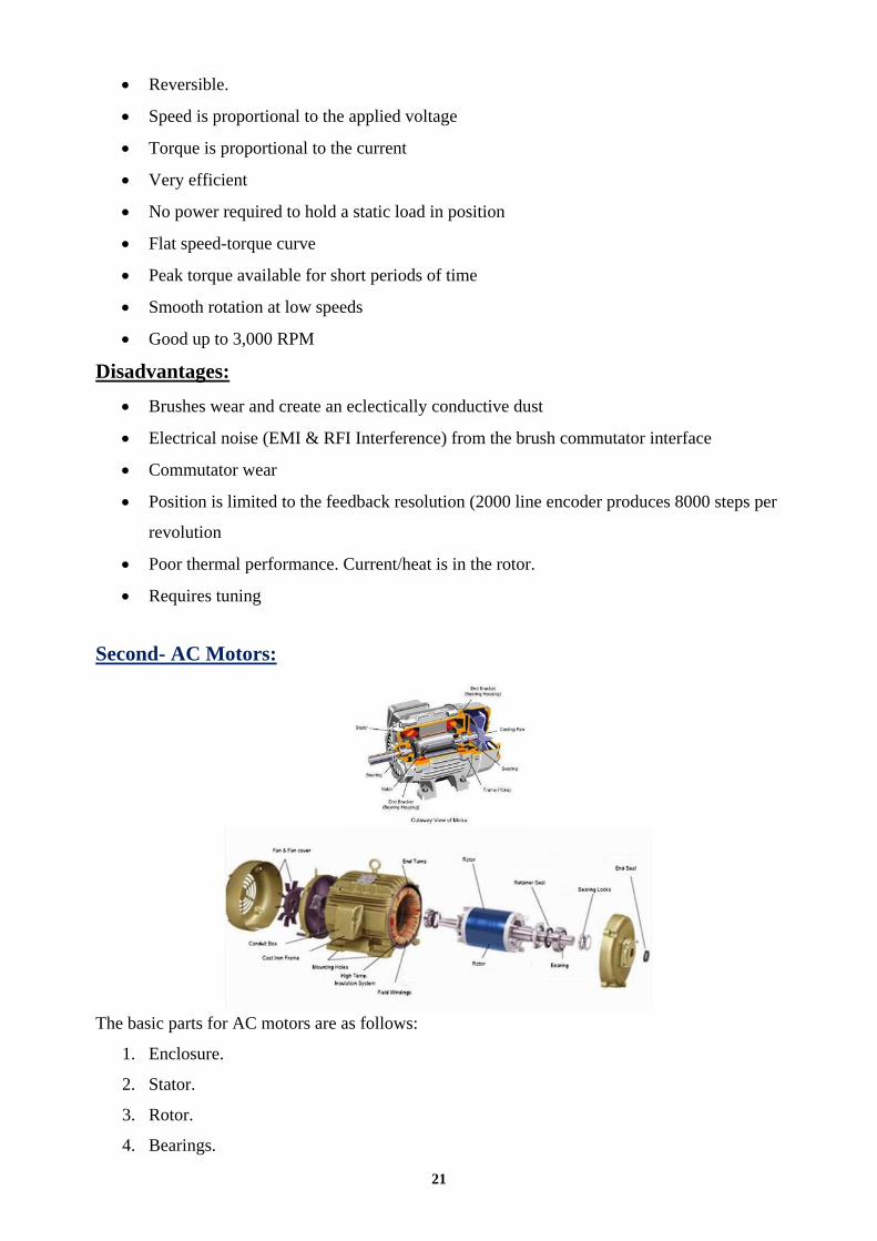
Fig.5.12 a: The output voltage of comparator IC 741 pin 6, from practical point of view.
(Flexible broad board and Hard copper board).
0 0.005 0.01 0.015 0.02 0.025 0.03 0.035 0.04 0.045 0.05
0
0.2
0.4
0.6
0.8
1
1.2
1.4
1.6
Fig.5.12 b: The output voltage of comparator, from simulation point of view.

71
At frequency f= 2.05 K Hz
Fig.5.11 a: Ilustrate the triangular with dc voltge
0 0.005 0.01 0.015 0.02 0.025 0.03 0.035 0.04 0.045 0.05
-1.5
-1
-0.5
0
0.5
1
1.5
Fig.5.11 b: The triangular and DC voltge from simulation point of view.
72
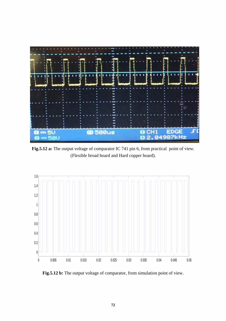
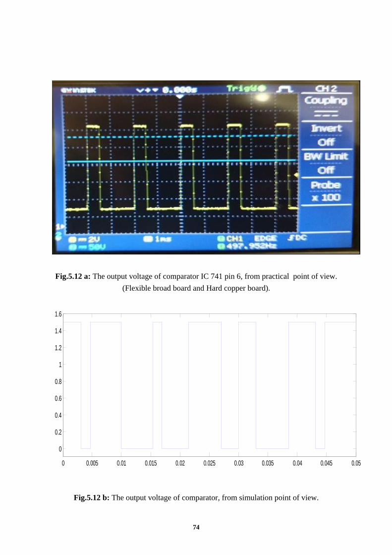
Fig.5.12 a: The output voltage of comparator IC 741 pin 6, from practical point of view.
(Flexible broad board and Hard copper board).
0 0.005 0.01 0.015 0.02 0.025 0.03 0.035 0.04 0.045 0.05
0
0.2
0.4
0.6
0.8
1
1.2
1.4
1.6
Fig.5.12 b: The output voltage of comparator, from simulation point of view.

73
At frequency f= 500 Hz
Fig.5.11 a: Ilustrate the triangular with dc voltge
0 0.005 0.01 0.015 0.02 0.025 0.03 0.035 0.04 0.045 0.05-1.5
-1
-0.5
0
0.5
1
1.5
Fig.5.11 b: The triangular and dc voltge from simulation point of view.
74
Fig.5.12 a: The output voltage of comparator IC 741 pin 6, from practical point of view.
(Flexible broad board and Hard copper board).
0 0.005 0.01 0.015 0.02 0.025 0.03 0.035 0.04 0.045 0.05
0
0.2
0.4
0.6
0.8
1
1.2
1.4
1.6
Fig.5.12 b: The output voltage of comparator, from simulation point of view.

75
- Compartor between triangular and sin wave
Triangle 725Hz
0 0.01 0.02 0.03 0.04 0.05 0.06 0.07 0.08 0.09 0.1-1.5
-1
-0.5
0
0.5
1
1.5

76
0 0.01 0.02 0.03 0.04 0.05 0.06 0.07 0.08 0.09 0.1-0.2
0
0.2
0.4
0.6
0.8
1
1.2
1.4
1.6

77
Triangle 500Hz and Sine 1KHz
0 0.01 0.02 0.03 0.04 0.05 0.06 0.07 0.08 0.09 0.1
-1.5
-1
-0.5
0
0.5
1
1.5

78
Triangle 225Hz
0 0.01 0.02 0.03 0.04 0.05 0.06 0.07 0.08 0.09 0.1
-1.5
-1
-0.5
0
0.5
1
1.5

79
PWM at Triangle 225Hz and Sine 1KHz.
0 0.01 0.02 0.03 0.04 0.05 0.06 0.07 0.08 0.09 0.1-0.2
0
0.2
0.4
0.6
0.8
1
1.2
1.4
1.6

80
Sine 1KHz

81
Triangle 725Hz and Sine 1KHz.
0 0.01 0.02 0.03 0.04 0.05 0.06 0.07 0.08 0.09 0.1-1.5
-1
-0.5
0
0.5
1
1.5

82
Triangle 500Hz

83
PWM at Triangle 500Hz and Sine 1KHz.

84
Triangle 225Hz and Sine 1KHz

85
Finally the Graduation Project is illustrated in Fig.5.13. as a practical flexible
& hard copper board of drive circuit under test.
Fig.5.13: Practical flexible & hard copper board of drive circuit under test.

86
CHAPTER 7
CONCLUSION

87
CONCLUSION
The simulation and experimental implementation for the system is presented. A fixed
structure controller is presented for four different converter types. The controller objective is to
move the operating point of the system to its desired voltage. The converter duty cycle (D) is
adjusted by the controller to track the system voltage.

88
A- References
1. http://en.wikipedia.org/wiki/Boost_converter
2. http://en.wikipedia.org/wiki/Buck_converter
3. http://en.wikipedia.org/wiki/Buck–boost_converter
4. http://en.wikipedia.org/wiki/Ćuk_converter
5. U.A.Bakshi and M.V.Bakshi. Electrical Drives And Control. 1st ed. Technical
Publications Pune, 2009. Page 1-1 Published by Ohio Electric
Motors: http://www.ohioelectricmotors.com/a-guide-to-electric-drives-and-DC-motor
control-688#ixzz2StwEZqtL
6. N. K. De and P. K. Sen. Electric Drives. Prentice Hall of India, 2006. Page 1 Published by
Ohio Electric Motors: http://www.ohioelectricmotors.com/a-guide-to-electric-drives-and-
DC-motor-control-688#ixzz2StxUzYio
7. Herman, Stephen L. Industrial Motor Control. 6th ed. Delmar Cengage Learning, 2010.
Page 7 Published by Ohio Electric Motors: http://www.ohioelectricmotors.com/a-guide-
to-electric-drives-and-DC-motor-control-688#ixzz2StyCFF8u
8. http://www.vishay.com/docs/81865/4n32.pdf For IC 4N32
9. http://www.ti.com/lit/ds/symlink/lm741.pdf For IC 741
10. http://www.intersil.com/data/FN/FN2864.pdf For IC 8038
11. http://www.datasheetcatalog.com For IC 7414
12. www.fairchildsemi.com/ds/LM/LM7805.pdf For IC 78XX

89
CAPSTONE DESIGN PROJECT
Project Submission and
ABET Criterion 3 a-k Assessment Report
Project Title: PRACTICAL DESIGN AND TESTING FOR DRIVE CIRCUIT OF
MACHINE USING PULSE WIDTH MODULATION ( P.W.M )
DATE: May / 2013
PROJECT ADVISORS: Dr. Ahmed Oshaba
Team Members:
Design Project Information
Percentage of project Content- Engineering Science % 40%
Percentage of project Content- Engineering Design % 60%
Other content % All fields must be added to 100% __________________ Please indicate if this is your initial project declaration □ Project Initial Start Version or final project form (Final) □ Final Project Submission Version
Do you plan to use this project as your capstone design project? yes
Mechanism for Design Credit (Projects in Engineering Design)
□ Projects in Engineering Design
□ Independent studies in Engineering □ Engineering Special Topics
Fill in how you fulfill the ABET Engineering Criteria Program Educational
Outcomes listed below
Outcome (a), An ability to apply knowledge of mathematics,
science, and engineering fundamentals.
Please list here all subjects (math, science, engineering) that have
been applied in your project. For Example: let’s consider a MCUPE (Machine Control Using Power
Electronics) system, this, include`:
Electrical Machine, Control System, Drive Circuit, Converter, Control
Theory, Feedback Systems, Electronic Control, Electrical Engineering,
…. and so on.

90
Outcome (b). An ability to design and conduct experiments,
and to critically analyze and interpret data.
In this part, if the project included experimental work for
validation and/or verification purposes, please indicate that.
Consider the pervious example in outcome (a) (i.e. MCUPE system)
Validation of Actual Electrical Machine Control, …etc.
Outcome (c). An ability to design a system, component or
process to meet desired needs within realistic
constraints such as economic, Environmental,
Social, political, ethical, health and safety,
manufacturability, and sustainability
All projects should include a design component. By design we
mean both physical and non physical systems. Designing a MCUPE system, this, or Electrical Machine, Control Part,
Drive Circuit, Converter, Feedback Part, Electronic and IC. (integrate
circuit) Component., Electrical, …. and so on would be considered a
physical system.
On the other hand, this project had a non-physical part, such as: the real
data, supplied by the industry.
Outcome (d). An ability to function in multi-disciplinary
teams.
This outcome is achieved automatically by the fact that all projects
composed of at least 3 students. However, if the project involved
students from other departments, that would be a plus that is worth
to be highlighted. The number of students in this project is 5
working together anther group in the laboratory.
Outcome (e). An ability to identify, formulate and solve
engineering problems.
In order to meet this specific outcome, it would help if you have a
Problem Statement section in your project report. If not, then
briefly highlight how the “students” were able identify, formulate
and solve the project’s problem.
The main problem is how to control the motor speed using
hardware and software programming.
Outcome (f). An understanding of professional and ethical
responsibility.
Here professional and ethical responsibility depends on the project
context. The MCUPE project it would be not ethical.
Outcome (g). An ability for effective oral and written
communication.
Good report and good presentation will fulfill this outcome
Outcome (h). The broad education necessary to understand
the impact of engineering solutions in a global
economics, environmental and societal context
.
This outcome is usually fulfilled by highlighting the economic
feasibility of the project, and emphasizing that the project would
not harm the environment and does not negatively affect human
subjects.
Outcome (i). A recognition of the need for, and an ability to
engage in life-long learning.
This outcome is fulfilled by suggesting a plan for future studies
and what else could be done based on the outcome of the current
project.
In the future IGBT devices and data acquisition card for control
system will be use.
Outcome (j). A knowledge of contemporary issues.
Extensive literature review for machine control, types of drive
circuit, converter (Buck, Cuk and Buck-Boost) and , overall control
system of machine by the “students” for the current state of the art
will fulfill this outcome.
Outcome (k). List all technologies included in the project (hardware and
software)

91
An ability to use the techniques, skills, and
modern engineering tools necessary for
engineering practice.
1) Using software program Matlab/simulink for simulation
2) Using hardware to build hard copper board the drive circuit
By signing below certify that this work is your own and fulfills the criteria
described above
Student Team Signatures __________________________
__________________________
__________________________
__________________________
__________________________
Project Advisor Signature _________________________
College Coordinator of Capstone Projects _________________________
Approved By _________________________

92
B-Appendices
B-1 List of Components
TYPE QUANTITY PRICE IN S.R.
Resistance 220Ω 3 6
Resistance 3.3KΩ 3 6
Resistance 10KΩ 21 42
Resistance 91KΩ 6 12
Resistance 100KΩ 12 24
Rheostat 20KΩ 12 48
Diode 12 24
Capacitor 0.0015µF 6 12
Capacitor 0.1µF 6 12
Capacitor 10µF 15 30
Capacitor 2200µF 15 60
Transformer 3 180
Bridge 12 36
LM7812 6 24
LM7912 3 12
LM7815 3 12
LM7805 3 12
4N32 3 15
DM7414 3 15
LM741 3 15
ICL8038 6 120
IC Sockets 18 36
Junction points 3 9
Tray of connecting wires 6 30
Fine solder 1 40
Desoldering pump 1 35
Caustic 1 120
Peeler 1 40
Pliers 1 20

93
B-2 Integrated Circuits IC’S
Datasheets
94
A Senior Project Final Report submitted in partial fulfillment
of the requirement for the degree of BACHELOR OF Science (B.Sc.),
in Electrical Engineering
( Completion Date May / 2013 )
جـايــــعـة جــــــــــــازا
كـهـــــــــة انـــــــــهــــذســــــــــــة
قـــســــى انـــهــذســـــــــة انــكــهــرتـــائــــــــــة
تصمين عملي واختباس دائشة تغزيت
لآلالث باستخذام تعذيل عشض النبضت
رو القيمت والتشدد
طالب فرق انعم
سذ عطف-6ثم عشىي -1
عثذهلل كرري-7اتراهى اتكر عسه -2
جاترانانك- 8سهطا حس عسري -3
سعذ انتهذي -9طارق قس -4
يتعة انذوسري -10شرف اتى انىر عثذهلل -5
يشرف انشروع
احمد سعيد عشيبة / د
تقرر يشروع انتخرج يقذو نهحصىل عهى درجة انثكانىرىش
ةائانكهربف انهذسة