Design of Picton Railway Overbridge for Mine Subsidence
28
Design of Picton Railway Overbridge for Mine Subsidence Geraint Jones Long Bai Small Bridges Conference 24 November 2015
Transcript of Design of Picton Railway Overbridge for Mine Subsidence
Design of Picton
Railway Overbridge
for Mine Subsidence
Geraint Jones
Long Bai
Small Bridges Conference
24 November 2015

>Project Background
>Longwall Mining
>Location & Setting
>Proposed Works
>Stakeholders
>Program Milestones
>Detailed Design
> Mine Subsidence
> Articulation
> Spherical Bearings
> Modular Joint
> Maintenance Manual
>Conclusions
Introduction - Presentation Structure

Longwall Mining

Location & Setting


Proposed Works

Stakeholders

>Oct 2014 Commence Detailed Design
>Jan 2015: Detailed Design Complete
>Mar 2015: Tender Period
>May 2015: Award Contract
>June 2015 Commence Construction
>Nov 2015: Demolish Existing & Open New Bridge to Traffic
>Dec 2015: Anticipated first impact of Longwall
>Jan 2016: Longwall expected to be directly under the Bridge
>Mar 2016: Longwall expected to be complete
Program Milestones
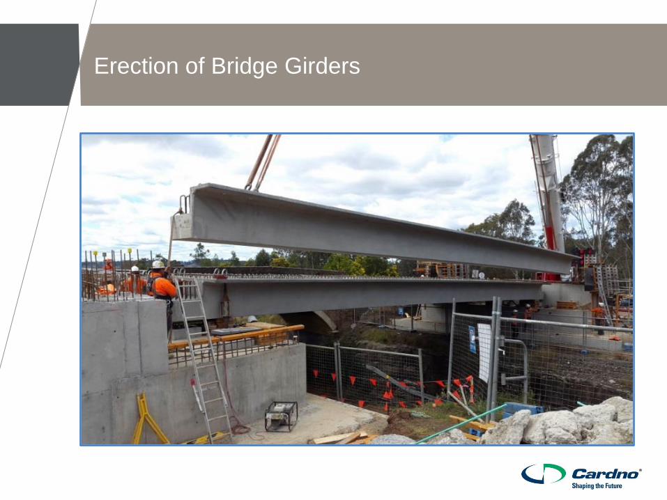
Erection of Bridge Girders

Demolition of Existing Bridge

Bridge Design
1. Design Strategy
2. Bridge Articulation
3. Mining Subsidence Movements
4. Maintenance
5. Conclusion

Bridge Geometry

Design Strategy
>Design Guidance: BD10/97
>Special consideration is required if the
displacement between two points exceeds
1/1000 times the distance
>Mine subsidence prediction was carried out by
Mine Subsidence Engineering Consultants
(MSEC)
>Not economical to design all the elements and
connections to accommodate the worst
predicted movement
>Key challenge: A economical articulation
system that requires minimum intervention and
adjustment during or after the mining activities.

Mine Subsidence Movement Register
>Subsidence Movement Scenario
>Potential Response of Overbridge
>Potential Impact on Overbridge
>Predicted Movement
>Design Strategy
>Proposed Design Capacity
>Subsidence Management Strategy
>Trigger Level

Mine Subsidence Movement
Subsidence movement
scenario
Predicted Movements
1% Probability 0.05% Probability Worst Observed Maximum
Closure between
abutments
80 mm 230 mm 330 mm 500 mm
Opening between
abutments
35 mm 70 mm 80 mm 150 mm
Lateral differential
movement between
abutments
40 mm 80 mm 84 mm 150 mm
Vertical differential
movement between
abutments
50 mm 100 mm 330 mm 400 mm or 10mm/m
whichever is greater
Uniform lateral tilt
N/A N/A - 10mm/m
Transverse differential tilt
(twist) between abutments
- - - 10mm/m
Curvature of ground at
abutment transverse to bridge
- - - Hogging or sagging
curvature of 0.10km-1
Tension strain of ground at
abutment transverse to bridge
1.5mm/m 2.9mm/m - -
Compression strain of ground
at abutment transverse to
bridge
-3.5mm/m -9.7mm/m - -

Articulation
Abutment A
> Modular Expansion Joint
Abutment B
> Strip Seal Expansion Joint
Girders
> Spherical Bearings
Traffic Barrier Connector
Cover Plate
Safety Screen

Bearings & Lateral Restraints
Abutment A
> Free floating bearings under all girders
> Later restraint block between two middle girders
Abutment B
> Free floating bearings under two outer girders
> Fixed bearing under middle bearing

Articulation Movement Capacity
Element Opening Closing Vertical
Rotation
Horizontal
Rotation
Modular Expansion
Joint (Abutment A)
185 mm 535 mm +/- 0.03 rad +/- 0.01 rad
Strip Seal Joint
(Abutment B)
82 mm 43 mm - -
Free Floating Bearing
(Abutment A)
185 mm 535 mm +/- 0.03 rad -
Free Floating Bearing
(Abutment B)
28 mm 28 mm +/- 0.03 rad -
Traffic Barrier
Connector
120 mm 100 mm - -
Cover Plates 100 mm 230 mm - -
Safety Screen 55 mm 20 mm - -

Predicted conventional closure: 20 mm.
1 in 100: 80 mm
1 in 2000: 230 mm
Worst observed: 330 mm
Maximum Predicted: 500 mm
Closure Between Abutments

Opening Between Abutments
Predicted conventional opening: 25 mm.
1 in 100: 35 mm
1 in 2000: 70 mm
Worst observed: 80 mm
Maximum Predicted: 150 mm

Lateral Movement Between Abutments
1 in 100: 40 mm
1 in 2000: 80 mm
Worst observed: 84 mm
Maximum Predicted: 150 mm

Vertical Movement Between Abutments
Predicted conventional tilt: 2 mm/m.
1 in 100: 50 mm
1 in 2000: 100 mm
Worst observed: 330 mm
Maximum Predicted: 10 mm/m or 400 mm (whichever is greater)

Modular Expansion Joint
Picture Courtesy to Mageba
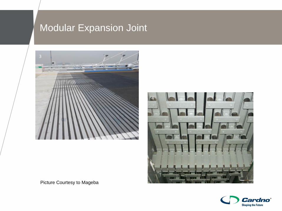
Modular Expansion Joint
Picture Courtesy to Mageba

Modular Expansion Joint
Picture Courtesy to Mageba
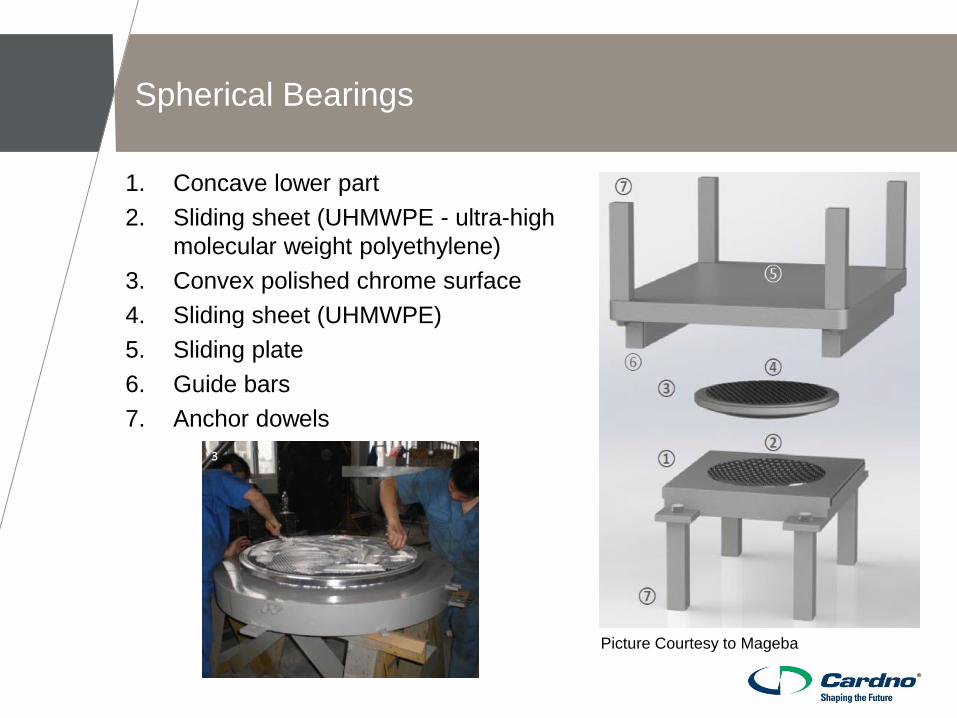
Spherical Bearings
1. Concave lower part
2. Sliding sheet (UHMWPE - ultra-high
molecular weight polyethylene)
3. Convex polished chrome surface
4. Sliding sheet (UHMWPE)
5. Sliding plate
6. Guide bars
7. Anchor dowels
Picture Courtesy to Mageba

Maintenance
Asset element/Sub-element Minimum Design life (years)
Permanent Structural Elements 100
Spherical Bearings 40
Bridge Joints – Joint sealant 15
Bridge Joints – Expansion joint rubbers 35
Safety Screens – Protective Coating 15
Asphalt Wearing course 40
Traffic Barrier Railings – Protective coating 20
>Design Life of Bridge Elements
>Maintenance Diary of Bridge Elements
>Inspection and Maintenance Instructions
>Work-As-Executed Drawings

The design for this single span bridge of modest dimensions was relatively
complex due to the requirement that the bridge should accommodate potential
significant mining induced ground movements without intervention or adjustment.
Through consultation with a wide range of parties an efficient and robust design
solution was achieved.
The existing bridge was demolished and the new bridge constructed with
minimum disruption to road and rail users and with no delay to the longwall
mining operations.
Conclusion
Acknowledgements
Kevin Golledge Tahmoor Coal
David Talbert Tahmoor Coal
Ian Sheppard Tahmoor Coal
Daryl Kay MSEC
Mark Dolan Robson Civil
Virendra Ghodke Mageba