Design of Hybrid Propulsion Systems for Unmanned … Institute of Aeronautics and Astronautics 1...
14
American Institute of Aeronautics and Astronautics 1 Design of Hybrid Propulsion Systems for Unmanned Aerial Vehicles Dr. Junghsen Lieh 1 and Mr. Eric Spahr 2 Wright State University, Dayton, Ohio 45435 USA Dr. Alireza Behbahani 3 and Mr. John Hoying 4 Air Force Research Laboratory, Wright-Patterson AFB, OH, 45433, USA A hybrid electric propulsion system with two or more energy sources has many advantages over conventional internal combustion (IC) engine power trains. The most recognized advantages are its low pollution, low noise, and reduced heat release. The application of hybrid electric propulsion for highway vehicles has successfully improved energy efficiency and reduced pollution. In the military, hybrid electric unmanned aerial vehicles (UAVs) can be used effectively because they possess the capability for long flight time, better efficiency and stealth operation. According to DOD’s roadmap, conventional UAVs have made 500,000 flight hours in support of military missions as of October 2008. And the flight hours and functions of UAVs are expected to increase because their application may be expanded from military to civil service (such as for monitoring and detecting disaster, hazard, and environment conditions, and reserving backup power for emergency). Four hybrid propulsion models are considered in the paper, namely secondary shaft dual- clutch, secondary shaft single-clutch, inline and planetary gear models. Among these four models, three prototypes for secondary shaft and inline configurations are built and presented. I. Introduction HE shortage of fossil fuels and increased toxic emissions threaten the sustainability of engine-powered aircraft propulsion systems. Soaring fuel costs have a negative impact on the airline industry and also result in an increasing military budget. Of all possible remedies, hybrid electric propulsion systems are generally considered. It is known that hybrid electric propulsion systems possess many advantages over engine-alone systems. With the successful implementation of hybrid electric drive trains to highway vehicles, more and more researchers are applying hybrid concepts to other machinery; typical examples are aerial vehicles and ships. In recent years, the development of hybrid electric UAVs has become one of the main tasks of the military in order to improve vehicles’ flight time, energy efficiency and stealth operation. Hybrid UAVs are not only considered for military application, they are also considered for civil service (for monitoring disaster and environment conditions, and serving as backup power in case of engine failure). Hybrid electric propulsion systems can be beneficial to the Air Force’s growing fleet of UAVs, many of which are small propeller-driven vehicles with similar flight characteristics to model planes. The benefits of a hybrid system include quiet operation, reduced heat signature, battery recharging during flight, allowing downsized ICE for cruise mode, having a back-up power source, reverse motor ICE starting, and in-air ICE restart. Thus, it is feasible that these UAVs could be easily adapted to hybrid configurations. This transition not only has the potential to increase flight hours and reduce fuel consumption but also has the potential to enable the vehicle to conduct sensitive surveillance operations in a stealth “electric-alone” mode, which provides significant noise and heat signature reductions over IC engine configurations. The development of hybrid electric-engine propulsion systems can be traced back to the 1980s. Since then many hybrid configurations were rapidly evolved, mainly for ground vehicles. The application of hybrid electric concepts to marine vehicles was reported by Barcaro, Bianchi and Bolognani and Sortland in 2008. 1 Professor, Mechanical & Materials Engineering 2 Graduate Student, Mechanical & Materials Engineering 3 AIAA Associate Fellow, Senior Aerospace Engineer, Propulsion Directorate, 1950 Fifth St. WPAFB, OH 4 Aerospace Engineer, Propulsion Directorate, 1950 Fifth St. WPAFB, OH T 47th AIAA/ASME/SAE/ASEE Joint Propulsion Conference & Exhibit 31 July - 03 August 2011, San Diego, California AIAA 2011-6146 Copyright © 2011 by the American Institute of Aeronautics and Astronautics, Inc. All rights reserved.
-
Upload
nguyenthien -
Category
Documents
-
view
220 -
download
1
Transcript of Design of Hybrid Propulsion Systems for Unmanned … Institute of Aeronautics and Astronautics 1...
American Institute of Aeronautics and Astronautics
1
Design of Hybrid Propulsion Systems for Unmanned Aerial
Vehicles
Dr. Junghsen Lieh1 and Mr. Eric Spahr
2
Wright State University, Dayton, Ohio 45435 USA
Dr. Alireza Behbahani3 and Mr. John Hoying
4
Air Force Research Laboratory, Wright-Patterson AFB, OH, 45433, USA
A hybrid electric propulsion system with two or more energy sources has many advantages over
conventional internal combustion (IC) engine power trains. The most recognized advantages are its low
pollution, low noise, and reduced heat release. The application of hybrid electric propulsion for highway
vehicles has successfully improved energy efficiency and reduced pollution. In the military, hybrid electric
unmanned aerial vehicles (UAVs) can be used effectively because they possess the capability for long flight
time, better efficiency and stealth operation. According to DOD’s roadmap, conventional UAVs have made
500,000 flight hours in support of military missions as of October 2008. And the flight hours and functions of
UAVs are expected to increase because their application may be expanded from military to civil service (such
as for monitoring and detecting disaster, hazard, and environment conditions, and reserving backup power
for emergency). Four hybrid propulsion models are considered in the paper, namely secondary shaft dual-
clutch, secondary shaft single-clutch, inline and planetary gear models. Among these four models, three
prototypes for secondary shaft and inline configurations are built and presented.
I. Introduction
HE shortage of fossil fuels and increased toxic emissions threaten the sustainability of engine-powered aircraft
propulsion systems. Soaring fuel costs have a negative impact on the airline industry and also result in an
increasing military budget. Of all possible remedies, hybrid electric propulsion systems are generally considered.
It is known that hybrid electric propulsion systems possess many advantages over engine-alone systems. With
the successful implementation of hybrid electric drive trains to highway vehicles, more and more researchers are
applying hybrid concepts to other machinery; typical examples are aerial vehicles and ships. In recent years, the
development of hybrid electric UAVs has become one of the main tasks of the military in order to improve vehicles’
flight time, energy efficiency and stealth operation. Hybrid UAVs are not only considered for military application,
they are also considered for civil service (for monitoring disaster and environment conditions, and serving as backup
power in case of engine failure).
Hybrid electric propulsion systems can be beneficial to the Air Force’s growing fleet of UAVs, many of which
are small propeller-driven vehicles with similar flight characteristics to model planes. The benefits of a hybrid
system include quiet operation, reduced heat signature, battery recharging during flight, allowing downsized ICE for
cruise mode, having a back-up power source, reverse motor ICE starting, and in-air ICE restart. Thus, it is feasible
that these UAVs could be easily adapted to hybrid configurations. This transition not only has the potential to
increase flight hours and reduce fuel consumption but also has the potential to enable the vehicle to conduct
sensitive surveillance operations in a stealth “electric-alone” mode, which provides significant noise and heat
signature reductions over IC engine configurations. The development of hybrid electric-engine propulsion systems
can be traced back to the 1980s. Since then many hybrid configurations were rapidly evolved, mainly for ground
vehicles. The application of hybrid electric concepts to marine vehicles was reported by Barcaro, Bianchi and
Bolognani and Sortland in 2008.
1 Professor, Mechanical & Materials Engineering
2 Graduate Student, Mechanical & Materials Engineering
3 AIAA Associate Fellow, Senior Aerospace Engineer, Propulsion Directorate, 1950 Fifth St. WPAFB, OH
4 Aerospace Engineer, Propulsion Directorate, 1950 Fifth St. WPAFB, OH
T
47th AIAA/ASME/SAE/ASEE Joint Propulsion Conference & Exhibit31 July - 03 August 2011, San Diego, California
AIAA 2011-6146
Copyright © 2011 by the American Institute of Aeronautics and Astronautics, Inc. All rights reserved.
American Institute of Aeronautics and Astronautics
2
The research of hybrid-energy powered aerial vehicles was also initiated in the 1980s. Youngblood, Talay and
Pegg developed an unmanned airplane by incorporating solar and fuel cell propulsion in 1984. An early version of a
hybrid solar electric-engine remotely piloted aerial vehicle was developed by Harmats and Weihs in 1999. Its
propulsion system includes solar cells, a battery pack, an electric motor, and an IC engine. A series hybrid electric
micro air vehicle (MAV) model was recommended by Wilson in 2002. From theoretical simulation results, Freeh,
Liang, Berton and Wickenheiser indicated that various hybrid configurations may be beneficial to airplanes based on
the technical and financial success of battery/IC engine automobile hybrids currently in the market. Simulation
results from a mathematical model developed by Harmon, Frank and Joshi, and Harmon, Frank and Chattot showed
that hybrid electric propulsion can be used for UAVs. The most recently reported hybrid electric UAV was designed
by a research team of National Cheng-Kung University and its debut flight test was successfully conducted on May
13, 2010. This new hybrid UAV was powered by a fuel cell plant, a brushless DC (BLDC) motor and a lithium-ion
battery, and is able to fly at a speed of 80-100 km/h.
The first pilot-operated serial hybrid electric airplane, DA36 E-Star, was developed by Siemens (Paur, 2011).
The debut flight of the hybrid electric airplane was completed on June 8, 2011. Its propulsion system includes a 94-
HP motor to power the propeller and a 40-HP Wankel rotary engine to drive a generator that charges the battery.
II. Review of Hybrid Electric Propulsion Drive Trains
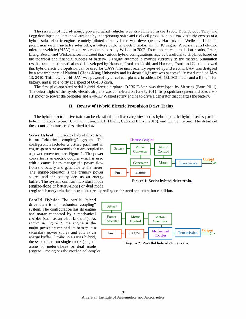
The hybrid electric drive train can be classified into five categories: series hybrid, parallel hybrid, series-parallel
hybrid, complex hybrid (Chan and Chau, 2001; Ehsani, Gao and Emadi, 2010), and fuel cell hybrid. The details of
these configurations are described below.
Series Hybrid: The series hybrid drive train
is an “electrical coupling” system. The
configuration includes a battery pack and an
engine-generator assembly that are coupled in
a power converter, see Figure 1. The power
converter is an electric coupler which is used
with a controller to manage the power flow
from the battery and generator to the motor.
The engine-generator is the primary power
source and the battery acts as an energy
buffer. The system can run individual mode
(engine-alone or battery-alone) or dual mode
(engine + battery) via the electric coupler depending on the need and operation condition.
Parallel Hybrid: The parallel hybrid
drive train is a “mechanical coupling”
system. The configuration has its engine
and motor connected by a mechanical
coupler (such as an electric clutch). As
shown in Figure 2, the engine is the
major power source and its battery is a
secondary power source and acts as an
energy buffer. Similar to a series hybrid,
the system can run single mode (engine-
alone or motor-alone) or dual mode
(engine + motor) via the mechanical coupler.
Engine Fuel
Power
Converter Motor/
Generator
Battery
Output
Figure 2: Parallel hybrid drive train.
Mechanical
Coupler Transmission
Motor
Control
Generator
Power
Converter
Transmission
Battery
Electric Coupler
Output
Figure 1: Series hybrid drive train.
Motor
Control
Motor
Fuel Engine

American Institute of Aeronautics and Astronautics
3
Series-Parallel Hybrid: The series-parallel hybrid
drive train consists of both electric and mechanical
couplers (see Figure 3). The system includes the
features of both series and parallel configurations, and
therefore can operate with single mode or dual mode, or
more modes than the above series or parallel drive train.
Complex Hybrid: The complex hybrid drive train also
consists of both electrical and mechanical couplers
similar to series-parallel system but with an
additional power converter added to it. Its
electric coupling function is moved from the
first power converter to the battery pack, as
shown in Figure 4. The system has the
features of both series and parallel
configurations, and therefore can operate with
individual mode or dual modes, or more
modes than an individual series or parallel
drive train.
Fuel Cell Hybrid: The configuration of fuel
cell hybrid electric propulsion is a series system similar to
the one described in Figure 1. The power lines are
electrically coupled. When applying to UAVs, the system
can be simplified as shown in Figure 5. The successful
flight of the fuel cell hybrid model conducted by NCKU on
May 13, 2010 proved that this fuel cell hybrid drive train
could be effectively implemented in modern UAVs.
III. Power Units For Hybrid Electric Propulsion Systems
IC Engines: There are many types of IC engines (see Figure 6); the best known types are the 4-stroke spark-ignited
engine, the 4-stroke compression-ignited diesel engine, the 2-stroke engine, the Wankel rotary engine, the gas
turbine engine, and the quasi-isothermal Brayton cycle engine. The Stirling engine is another type of engine that
uses external combustion. A combustion engine converts chemical energy into mechanical power. However, the
energy conversion process encounters high friction, low mechanical advantage, high heat loss, and serious pollution.
The energy efficiency of an engine is normally lower than 35% depending on its operating condition.
Electric Coupler
Figure 3: Series-parallel hybrid drive train.
Engine
Generator Fuel
Power
Converter
Motor
Battery
Output Mechanical
Coupler Transmission
Motor
Control
Electric Coupler
Fuel Cell Fuel
Power Converter
Motor
Battery
Output
Figure 5: Fuel cell hybrid electric drive train.
Controller
Figure 6: Different types of engines.
Rotary Engine
Reciprocating
IC Engine
Brayton Cycle
Wankel Engine
Gas Turbine
Atkinson Cycle
Jet Engine
Otto Cycle
2-stroke
4-stroke
6-stroke
Turbojet
Turbofan
Ramjet
Rocket
Diesel Engine
Nutating Engine
Diesel Cycle
Figure 4: Complex hybrid drive train.
Motor/
Generator
Power
Converter
Transmission
Battery
Electric Coupler
Output Mechanical
Coupler
Power
Converter
Motor Motor
Control
Fuel Engine
American Institute of Aeronautics and Astronautics
4
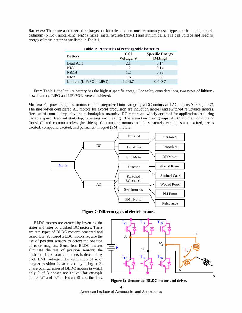
Batteries: There are a number of rechargeable batteries and the most commonly used types are lead acid, nickel-
cadmium (NiCd), nickel-zinc (NiZn), nickel metal hydride (NiMH) and lithium cells. The cell voltage and specific
energy of these batteries are listed in Table 1.
Table 1: Properties of rechargeable batteries
Battery Cell
Voltage, V
Specific Energy
[MJ/kg]
Lead Acid 2.1 0.14
NiCd 1.2 0.14
NiMH 1.2 0.36
NiZn 1.6 0.36
Lithium (LiFePO4, LiPO) 3.3-3.7 0.4-0.7
From Table 1, the lithium battery has the highest specific energy. For safety considerations, two types of lithium-
based battery, LiPO and LiFePO4, were considered.
Motors: For power supplies, motors can be categorized into two groups: DC motors and AC motors (see Figure 7).
The most-often considered AC motors for hybrid propulsion are induction motors and switched reluctance motors.
Because of control simplicity and technological maturity, DC motors are widely accepted for applications requiring
variable speed, frequent start/stop, reversing and braking. There are two main groups of DC motors: commutator
(brushed) and commutatorless (brushless). Commutator motors include separately excited, shunt excited, series
excited, compound excited, and permanent magnet (PM) motors.
BLDC motors are created by inverting the
stator and rotor of brushed DC motors. There
are two types of BLDC motors: sensored and
sensorless. Sensored BLDC motors require the
use of position sensors to detect the position
of rotor magnets. Sensorless BLDC motors
eliminate the use of position sensors; the
position of the rotor’s magnets is detected by
back EMF voltage. The estimation of rotor
magnet position is achieved by using a 3-
phase configuration of BLDC motors in which
only 2 of 3 phases are active (for example
points “a” and “c” in Figure 8) and the third
iac
Figure 8: Sensorless BLDC motor and drive.
a
b
c
V
Va
Vb
Vc
Tr1 Tr3 Tr5
Tr2 Tr4 Tr6
Sensorless
Sensored
DC
AC
DD Motor
Switched
Reluctance
Induction
Squirrel Cage
Wound Rotor
Reluctance
PM Rotor
Wound Rotor
Synchronous
Brushed
Motor
Hub Motor
Brushless
PM Hybrid
Figure 7: Different types of electric motors.

American Institute of Aeronautics and Astronautics
5
phase floats (inactive, point “b”) for a given rotor position.
Each phase of the BLDC motor may be described as an electrical-mechanical model as shown in Figure 9. The
equations describing the motor dynamics are
(1)
(2)
The motor efficiency is defined by the following equation:
(3)
In this equation, Pi is the 3-phase power in kW, Ph is the rated horse power, L% is the output power as % rated
power, and K is the efficiency correction factor.
Define e = Ker (see Figure 10), Eq. (1) becomes
(4)
The Laplace transform of the steady state solution of Eq. (3) is
(5)
Letting s = j results in V = (R + jL) I + E, where E = jE = j m is the EMF voltage, = 2f is the angular
frequency of sinusoidal input in radian/sec, and is the flux linkage of the stator winding per phase
induced by the permanent magnet. When E and I are in phase, the motor mechanical power output, i.e. the
electromagnetic output power (without friction, wind and iron losses) is Pem = m |E| |I| = m m I; here m is the
number of phases. From the relationship P=T, the electromagnetic torque can be written as
(6)
Define p as the number of poles, and r = 2/p is the rotor speed. The current (or electromagnetic torque) and
induced EMF voltage become
(or
) and
(7)
Define the shaft output load as Tload = Tem - Tloss, where Tloss is the total torque loss due to friction, iron hysteresis,
and windage. The voltage equation (for L<<R, and V, E and I in phase) can be simplified to
V = RI + E (8)
Substituting Eq. (7) into Eq. (8) results in
(9)
For a constant voltage supply, Eq. (9) is equivalent to a linear function (y = a – bx), and the corresponding torque-
speed (Tem ~ r) curve is plotted in Figure 11.

American Institute of Aeronautics and Astronautics
6
The above analysis is based on a simplified model. For better representing the 3-phase motor dynamics, a more
complicated model is needed and will be presented in the near future.
For the parallel hybrid electric configuration, the control scheme shown in Figures 12 and 13 is recommended.
Figure 13: Computer controlled hybrid electric UAV (similar for other configurations).
Clutch
Motor/
Generator
Battery
Engine
Control Engine
Fuel
Motor
Control
Power
Converter
Receiver
To Servos
Radio
Controller
Computer
D/A & A/D
Figure 11: Torque-speed
curve of a BLDC motor.
Tem 0
P
ro r r
cr TL
Figure 9: Equivalent circuit of each
phase of a BLDC motor.
Ker
T=KT i
J
Figure 12: Block diagram for hybrid electric propulsion systems.
System
Controller
Engine
Command
Motor
Command
Engine
Control
Motor
Control
Engine
Motor/
Generator
Propeller
PPS SOC
Fuel
Battery Power
Converter
Input
Signals
Figure 10: Equivalent circuit of
each phase of a BLDC motor.

American Institute of Aeronautics and Astronautics
7
IV. Propulsion Analysis For Small Aerial Vehicles
As shown in Figure 14, there are four major forces (thrust, lift, drag and weight) and one moment acting on the
airplane without considering the forces generated by control mechanisms (Anderson, 2008). The thrust F is
produced by the propeller or jet engine; the lift L is produced by the air when it passes over airfoil wings; the drag D
is an aerodynamic resistance; and the moment M is created by the coupling effect of aerodynamic downward and lift
forces (due to surface pressure and shear stress distributions on wings).
The lift (L) and drag (D) can be expressed as follows:
and
(10)
Where the symbols are defined as follows: S = wing area, CD = drag coefficient, CL = Lift coefficient, V = Velocity,
and = Air density. The thrust equals the total drag which is the sum of zero-lift drag and lift-induced drag:
(11)
For a small UAV (m = 10 kg, S = 1.0 m2, = 1.055 kg/m
3, CDo = 0.025, e = 0.8, AR = 10), the thrust-velocity
curve is shown in Figure 15. Similar to the thrust equation, the power can also be divided into two terms (namely
zero-lift power and lift-induced power):
(12)
Using the same parameters, the power-velocity curve is plotted in Figure 16. The liftoff distance can be
expressed by
(13)
Where, VLO is the liftoff velocity. To ensure a margin of safety during takeoff, the liftoff velocity is typically 20%
higher than the stalling velocity. That means
(14)
Substituting Eq. (14) into Eq. (13), the liftoff distance becomes
(15)
For estimation purposes, it is assumed that the average force occurs at V=0.7VLO. For the same UAV, the relation
between the liftoff distance and thrust is shown in Figure 17.
Figure 14: Free-body diagram of an airplane in flight.
Chord line
Horizontal
F
L
Flight path
W
T
D
M
V

American Institute of Aeronautics and Astronautics
8
Figure 15: Thrust-velocity curve.
Figure 16: Power-velocity curve.
Figure 17: Liftoff distance-thrust curve.
0 10 20 30 40 50 600
10
20
30
40
50Thrust vs. Velocity
Velocity, m/s
Thru
st,
N
0 10 20 30 40 50 600
0.5
1
1.5
2
2.5
3Power vs. Velocity
Velocity, m/s
Pow
er,
KW
0 10 20 30 40 50 600
50
100
150
200Liftoff Distance vs. Thrust
Thrust, N
Lifto
ff D
ista
nce,
m
American Institute of Aeronautics and Astronautics
9
V. Prototypes Of Parallel Hybrid Electric Propulsion Systems
The major difference of hybrid electric propulsion systems between highway and aerial vehicles is that highway
vehicles are required to operate in a stop-go mode, especially when driving in the city, but this is not the case for
aerial vehicles. The operation of aerial vehicles normally maintains the velocity in a nearly constant range except
during takeoff and landing. Among the five hybrid configurations described in the previous section, the parallel
hybrid configuration (Figure 2) is adopted. In order to reduce the weight (to maximize payload), a sensorless BLDC
motor and a LiPO battery pack are used. As for the engine, a four-stroke model is used.
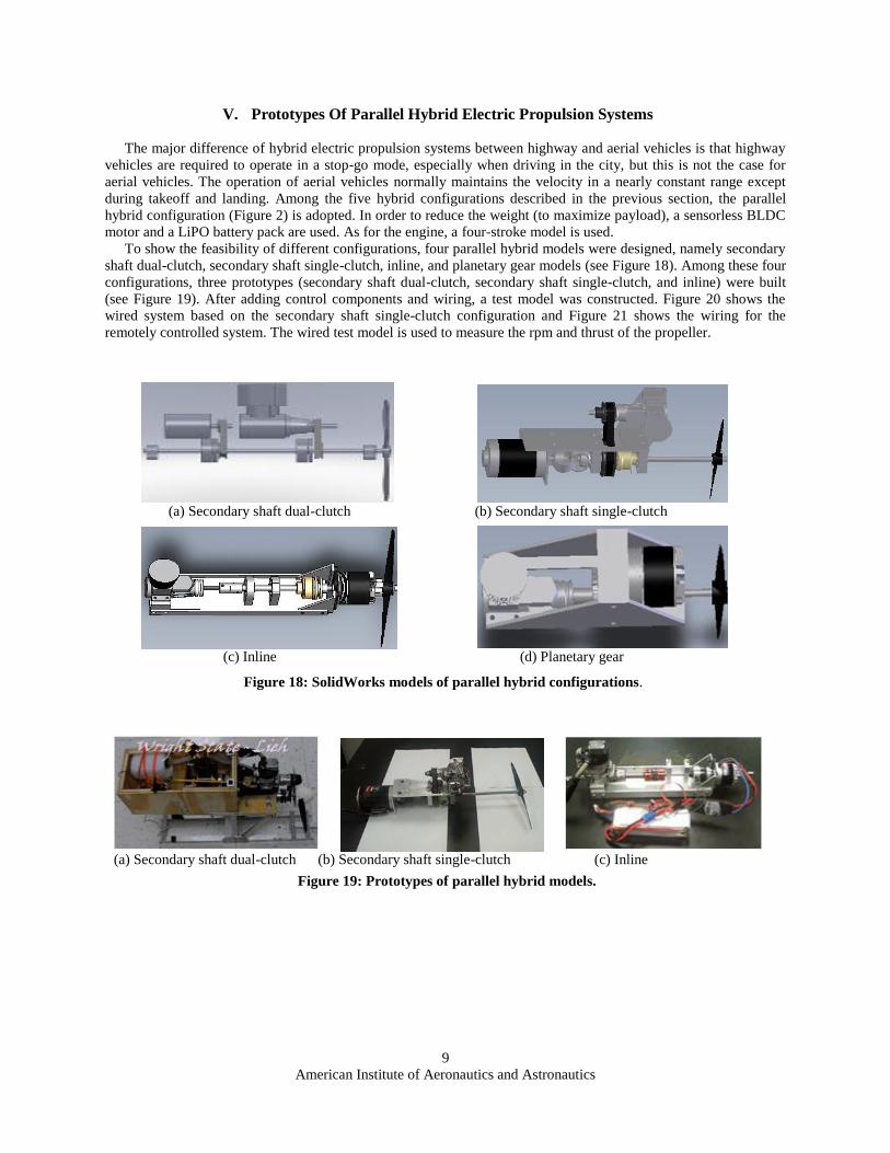
To show the feasibility of different configurations, four parallel hybrid models were designed, namely secondary
shaft dual-clutch, secondary shaft single-clutch, inline, and planetary gear models (see Figure 18). Among these four
configurations, three prototypes (secondary shaft dual-clutch, secondary shaft single-clutch, and inline) were built
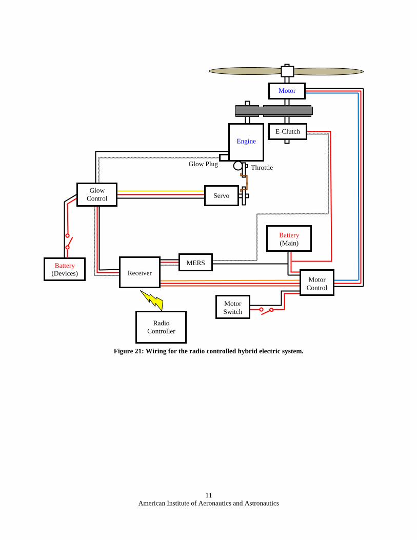
(see Figure 19). After adding control components and wiring, a test model was constructed. Figure 20 shows the
wired system based on the secondary shaft single-clutch configuration and Figure 21 shows the wiring for the
remotely controlled system. The wired test model is used to measure the rpm and thrust of the propeller.
(a) Secondary shaft dual-clutch (b) Secondary shaft single-clutch (c) Inline
Figure 19: Prototypes of parallel hybrid models.
(a) Secondary shaft dual-clutch (b) Secondary shaft single-clutch
(c) Inline (d) Planetary gear
Figure 18: SolidWorks models of parallel hybrid configurations.

American Institute of Aeronautics and Astronautics
10
Figure 20: Parallel hybrid model with control wiring on test stand.
VI. Summary And Recommendation
Due to time and budget restriction, only three prototypes were built. At this moment, test and evaluation of the
prototypes is still in a preliminary stage. Future work will include the following items:
1) Improve both secondary shaft and inline prototypes through additional testing and evaluation
2) Build a prototype of the planetary gear configuration for comparison
3) Develop a central self-tuning controller for operating the hybrid propulsion system and integrate with the
flight control
4) Install each prototype in a small aerial vehicle and conduct both lab and flight tests to optimize the designs
(maximum energy efficiency, minimum weight/size, increased payload, reduced noise/vibration, etc.)
5) Design full-scale hybrid electric propulsion models and install them in UAVs for further field testing and
evaluation
6) Improve the power storage capacity and life cycle of battery and fuel cells
7) Optimize the size and weight of the hybrid electric propulsion systems including downsizing the ICE for
cruise mode
VII. Conclusions And Further Research
This paper presents power control strategies for the propulsion of a UAV which is driven by a motor/battery and
ICE hybrid system. The UAV propulsion system has different power requirements in order to complete its mission
successfully. The different power stages in UAVs introduce taxiing, take off, cruising and landing. In this paper the
historical evolution of hybrid technology for UAVs and the challenges of implementing a hybrid propulsion
arrangement on future designs were discussed, and the following key features were revealed through this study. We
have reviewed the hybrid electric propulsion drive train along with its power units. In this paper we have
concentrated on the hardware aspect and making sure integration is part of the hybrid propulsion. Total UAV's
propulsive power and weight are the two dominant factors most likely to impact a future UAV employing hybrid
propulsion technology. A UAV's range and endurance, particularly for vehicles powered by electric propulsion, will
be a major issue. Current state of the art motor and battery technology limits electric-powered hobbyist helicopters
to less than a half-hour of flight at best. Further, there is little empirical information/insight into the design of very
small UAVs.
American Institute of Aeronautics and Astronautics
11
Figure 21: Wiring for the radio controlled hybrid electric system.
Radio
Controller
Glow Plug
Battery
(Devices)
Motor
MERS
Engine
Servo
E-Clutch
Throttle
Receiver
Glow
Control
Battery
(Main)
Motor
Control
Motor
Switch

American Institute of Aeronautics and Astronautics
12
VIII. References
[1] Clapper J.R., Young J.J., Cartwright J.E., Grimes J.G., Payton S.C., Stackley S.J. and Popps D., "FY2009–
2034 Unmanned Systems Integrated Roadmap," USA Department of Defense, 2009.
[2] Mehrdad Ehsani, “The Electrically Peaking Hybrid System and Method,” USPTO Patent No. 5,586,613, 1996.
[3] Rahman K.M. and Ehsani M., “Performance Analysis of Electric Motor Drives for Electric and Hybrid
Electric Vehicle Application,’’ Power Electronics Transportation, pp. 49–56, 1996.
[4] Yamaguchi K., Moroto S., Kobayashi K., Kawamoto M., and Miyaishi Y., “Development of a New Hybrid
System-Dual System,” SAE Journal Paper No. 970231, Warrendale, PA, 1997.
[5] Gao Y., Rahman M., and Ehsani M., “The Energy Flow Management and Battery Energy Capacity
Determination for the Drive Train of Electrically Peaking Hybrid,” SAE Journal, Paper No. 972647,
Warrendale, PA, 1997.
[6] Gao Y., Rahman M., Ehsani M., “Parametric Design of the Drive Train of an Electrically Peaking Hybrid,”
SAE Journal, Paper No. 970294, Warrendale, PA, 1997.
[7] Bates B., Belaire R.C., and Stephan C.H., “Hybrid Electric Propulsion System Using A Dual Shaft Turbine
Engine,” USTPO Patent No. 5,762,156, 1998.
[8] Assanis A., Delagrammatikes G., Fellini R., Filipi Z., Liedtke J., Michelena N., Papalambros P., Reyes D.,
Rosenbaum D., Sales A., and Sanena M., “Optimization Approach to Hybrid Electric Propulsion System
Design,” Mechanisms, structures and Machines, 27(4), pp. 393-421, 1999.
[9] Ehsani M., Gao Y., and Butler K.L., “Application of Electrically Peaking Hybrid (ELPH) Propulsion System
to a Full Size Passenger Car with Simulated Design Verification,’’ IEEE Transaction of Vehicular
Technology, Vol. 40, No. 6, November 1999.
[10] Rahman K.M., Fahimi B., Suresh G., Rajarathnam A.V., and Ehsani M., “Advanced of Switched Reluctance
Motor Applications to EV and HEV: Design and Control Issues,’’ IEEE Transaction Industry Application,
Vol. 36, No. 1, pp. 111–121, January/February 2000.
[11] Paganelli G., Ercole G., Brahma A., Guezennec Y., and Rizzoni G., “General supervisory control policy for
the energy optimization of charge-sustaining hybrid electric vehicles,” JSAE Review 22, pp. 511–518, 2001.
[12] Miller J.M., Ehsani M., and Gao Y., “Understanding Power Flows in HEV eCVT’s With Ultracapacitor
Boosting Using Simplorer,” In IEEE Power Propulsion Conference, Illinois Institute of Technology, Chicago,
Il, September 7–9, 2005.
[13] Gao Y., Ehsani M., and Miller J.M., “Hybrid Electric Vehicle Overview and State of The Art,” In Proceedings
of IEEE International Symposium on Industrial Electronics, ISIE’05, Dubrovnik, Croatia, Mini-Track on
Automotive Control (MTAC), June 20–23, 2005.
[14] Miller J.M. and Everett M., “Ultra-Capacitor Plus Battery Energy Storage System Sizing Methodology for
HEV Powersplit Electronic CVT’s,” In Proceedings IEEE International Symposium on Industrial Electronics,
ISIE’05, Dubrovnik, Croatia, Mini-Track On Automotive Control (MTAC), June 20–23, 2005.
[15] Miller J.M., “Hybrid Electric Vehicle Propulsion System Architecture Of The e-CVT Type,’’ IEEE
Transaction Power Electronics, Vol. 21, No. 3, pp. 756–767, 2005-2416-SI, May 2006.
[16] Cui S., Cheng Y., and Chan C.C., “A Study of Electrical Variable Transmission and Its Application in Hybrid
Electric Vehicle,” IEEE on Vehicle Power and Propulsion Conference, 2006.
[17] Chandler K. and Walkowicz K., “King County Metro Transit Hybrid Articulated Buses: Final Evaluation
Results,” EPRI Technical Report NREL/TP-540-40585, December 2006.
[18] Barnitt R. and Chandler K., “New York City Transit (NYCT) Hybrid (125 Order) and CNG Transit Buses,”
EPRI Technical Report NREL/TP-540-40125, November 2006.
[19] Markel T. and Simpson A., “Plug-In Hybrid Electric Vehicle Energy Storage System Design,” Advanced
Automotive Battery Conference Paper NREL/CP-540-39614, May 2006.
[20] Hadley S.W. and Tsvetkova A., “Potential Impacts of Plug-in Hybrid Electric Vehicles on Regional Power
Generation,” ORNL/TM-2007/150, 2007.
[21] Duvall M., “Plug-In Hybrid Vehicles –EPRI & Utility Perspective ,” EPRI 2007.
[22] Mahapatra S., Egel T., Hassan R., Shenoy R., and Carone M., “Model-Based Design for Hybrid Electric
Vehicle Systems,” MathWorks, 2008-01-0085, 2008.
[23] Camus C., Silva C.M., Farias T.L., and Esteves J., “Impact of Plug-in Hybrid Electric Vehicles in the
Portuguese Electric Utility System,” POWERENG, pp. 285-290, 2009.
[24] EPRI, “Impact of Plug-in Hybrid Electric Vehicles on Utility Distribution Systems,” EPRI, Feb. 2009.
[25] Taylor J., Maitra A., Alexander M., Brooks D., and Duvall M., “Evaluation of the Impact of Plug-in Electric
Vehicle Loading on Distribution System Operations,” RPRI, 2009.
American Institute of Aeronautics and Astronautics
13
[26] Wang F., Mao X.J., Zhuo B., Zhong H., and Ma Z.L., “Parallel Hybrid Electric System Energy Optimization
Control with Automated Mechanical Transmission,” Proc. IMechE, Vol. 223 Part D: Journal of Automobile
Engineering, pp. 151-, 2009.
[27] Zhang L.p., Lin C., and Niu X., “Optimization of Control Strategy for Plug-in Hybrid Electric Vehicle Based
on Differential Evolution Algorithm,” IEEE Power and Energy Engineering, APPEEC Asia-Pacific, PP. 1-5,
March 2009.
[28] Ehsani M., Gao Y., and Miller J., “Hybrid Electric Vehicles: Architecture and Motor Drives,” Proceedings of
IEEE, Vol. 95, No. 4, April 2007.
[29] Ehsan M., Gao Y., and Emadi A., Modern Electric, Hybrid Electric and Fuel Cell Vehicles, 2nd
Ed., CRC
Press: New York, 2010.
[30] Barcaro M., Bianchi N., and Bolognani S., “Hybrid Electric Propulsion System Using Submersed SPM
Machine,” Proceedings of the 2008 International Conference on Electrical Machines, Paper ID 923, 2008.
[31] Sortland S., “Hybrid Propulsion System for Anchor Handling Tug Supply Vessels,” Wärtsilä Technical
Journal, 01.2008, pp. 45-48, 2008.
[32] Youngblood J.W., Talay T.A., and Pegg R.J., “Design of Long-Endurance Unmanned Airplanes Incorporating
Solar and Fuel Cell Propulsion,” AIAA Paper 84-1430, June 1984.
[33] Harmats M. and Weihs D., "Hybrid-Propulsion High-Altitude Long-Endurance Remotely Piloted Vehicle,"
Journal of Aircraft, Vol. 36, pp. 321-331, April 1999.
[34] Wilson S.B., "Micro Air Vehicle Project," Proc. DARPA Technical Symposium, Anaheim, CA, 2002.
[35] Freeh J.E., Liang A., Berton J.J., and Wickenheiser T.J., "Electrical Systems Analysis at NASA Glenn
Research Center: Status and Prospects," Symposium on Novel and Emerging Vehicle and Vehicle Technology
Concepts, 2003.
[36] Harmon F.G., Frank A.A., and Joshi S.S., “The Control of a Parallel Hybrid-electric Propulsion System for a
Small Unmanned Aerial Vehicle Using a CMAC Neural Network,” Neural Networks 18 (2005) 772–780,
2005.
[37] Harmon F.G., Frank A.A., and Chattot J.J., “Conceptual Design and Simulation of a Small Hybrid-Electric
Unmanned Aerial Vehicle,” Journal OF AIRCRAFT, Vol. 43, No. 5, Sept–Oct 2006.
[38] “NCKU Fuel Cell and Lithium Battery Hybrid Powered Unmanned Aerial Vehicle Takes off Successfully in
Pingtung,” http://www.cna.com.tw/postwrite/cvpread.aspx?ID=58432, May 14, 2010.
[39] Miller M., Matthew Rippl, Jason Huwer, Brian Uhlenhake, Junghsen Lieh and Frederick G. Harmon,
“Verification of a Parallel Hybrid-Electric Propulsion System for an Unmanned Aircraft System,” Wright
State University, June 2009.
[40] Boyer C., Carper J., Joseph R., Wright S., and Lieh J., “Hybrid-Electric Propulsion System for Unmanned
Aerial System (UAS),” Wright State University, June 2010.
[41] Mastui N., “Sensorless PM Brushless DC Motor Drives,” IEEE Transaction on Industrial Electronics, Vol. 43,
April 1996.
[42] Class Notes for 48550 Electrical Energy Technology, “Chapter 14. Brushless DC Motors” and 48531
Electromechanical Systems: “Brushless DC Motors”, University of Technology, Sydney.
[43] Kettle P., Aengus Murray & Finbarr Moynihan, “Sensorless Control of a Brushless DC motor using an
Extended Kalman Estimator,” PCIM’98 Intelligant Motion, May 1998 Proceedings, pp. 385-392.
[44] Johnson J., “Review of Sensorless Methods for Brushless DC,” IAS, pp. 143-150, 1999.
[45] Shao J., Nolan D., and Hopkins T., “A Novel Microcontroller-based Sensorless Brushless DC (BLDC) Motor
Drive for Automotive Fuel Pumps,” Industry Applications Annual Meeting IAS’2002.
[46] Shao J., Nolan D., Hopkins T., “A Direct Back EMF Detection for Sensorless Brushless DC (BLDC) Motor
Drive and the Start-up Tuning,” Power Electronics Technology Conference, 2002.
[47] Shao J., Direct Back EMF Detection Method for Sensorless Brushless DC (BLDC) Motor Drives, MS thesis,
Virginia Polytechnic Institute and Sate University, September 2003.
[48] Varsani A., Low Cost Brushless DC Motor Controller, Thesis, Univ. of Queensland, Nov. 2003.
[49] Stefán Baldursson, BLDC Motor Modeling and Control – A Matlab/Simulink Implementation, Master Thesis,
May 2005.
[50] Yilmaz M., Tuncay R.N., and Üstün Ö., “Sensorless Drive of Brushless DC Motor Based Upon Wavelet
Analysis,” Istanbul Technical University.
[51] Ji H. and Li Z.Y., “Simulation of Sensorless Permanent Magnetic Brushless DC Motor Control System,” IEEE
Int. Conf. on Automation and Logistics, China, September 2008, pp. 2847-2851.

American Institute of Aeronautics and Astronautics
14
[52] Kim T.S., Park B.G., Lee D.M., Ryu J.S., and Hyun D.S., “A New Approach to Sensorless Control Method
for Brushless DC Motors,” International Journal of Control, Automation and Systems, Vol. 6, No. 4, pp. 477-
487, August 2008.
[53] Al-Mashakbeh A.S.O., “Proportional Integral and Derivative Control of Brushless DC Motor,” European
Journal of Scientific Research, Vol. 35, No. 2 (2009), pp.198-203.
[54] Chan C.C. and Chau K.T., Modern Electric Vehicle Technology, Oxford University Press, 2001.
[55] Anderson, J.D., Introduction to Flight, New York: McGraw-Hill, 2008.
[56] Paur J.,” Siemens Builds the Chevrolet Volt of Airplanes”, June 23, 2011,
http://www.wired.com/autopia/2011/06/electric-airplane-uses-hybrid-power-similar-to-chevy-volt/
[57] Lieh J and Behbahani A, “Green Energy Technologies to Improve Vehicle Propulsion Efficiency,” ISA2011,
57th
International Instrumentation Symposium, June 2011, St Louis, Missouri.
[58] Lieh J. and Behbahani A., “Development of Hybrid Electric Propulsion Systems for UAVs,” Technical Report,
Air Force Summer Faculty Fellowship Program, 2010.
[59] Electro-Craft, “DC Motors Speed Control Servo Systems,” Engineering Handbook, Electro-Craft Corporation,
New York, 1977.
[60] Atmel, “AVR444: Sensorless Control of 3-phase Brushless DC Motors,” Atmel Corporation, 2005.
[61] Xu H.S. and Jani Y., “Understanding Sensorless Vector Control for Brushless DC Motors,” Embedded Sys-
tems Conference, Silicon Valley, 2008.
[62] Aiken E.W., Ormiston R.A., and Young L.A., “Future Directions in Rotorcraft Technology at Ames Research
Center,” American Helicopter Society 56th
Annual Forum, Virginia May2-4, 2000.
[63] Gohardani A.S., Doulgeris G., and Singh R., “Challenges of Future Aircraft Propulsion: A Review of
Distributed Propulsion Technology And Its Potential Application for The All Electric Commercial Aircraft,”
Progress in Aerospace Sciences (2011), doi:10. 1016/j.paerosci.2010.09.001.