DESIGN CONCEPTS FOR THE CORE STRUCTURE OF A...
9
NUCLEARSTRUCTURALENGINEERlNG2 (1965)224-232. NORTH-HOLLANDPUBLISHINGCOMP., AMSTERDAM DESIGN CONCEPTS FOR THE CORE STRUCTURE OF A MOSEL (MOLTEN SALT EXPERIMENTAL) REACTOR * Paul R. KASTEN Molten Salt Reactor Program, Oak Ridge National Laboratory, Oak Ridge, Tennessee, USA Uri GAT, S.SCHULZEHORN Institut fur Reaktorentwicklung, Kernforschungsanlage Julich, Julich, Germany HeinzW.VORNHUSEN c/o Atomic Power Equipment Department, General Electric Company, San Jose, California, USA Received 26June 1965 General features ofa MOSEL(MOltenSalt ExperimentaL) reactor concept and a schematic flowdia- gram are given. Anumber ofcore designs appear capable of satisfying the requirements ofsuch reactor. Interacting parameters which need to be evaluated as a function ofoperating conditions are permissible tempera- ture distribution, stresses, nuclear performance, andfabrication possibility as a fu.nctionofcore de- sign. In general it appears that plate type designs facilitate lowfriction of structural material, achieve- ment of modular units, and fuel flow control. Tube-type designs appear advantageous relative to stress considerations andhigh fuel power density. 1. INTRODUCTION General and structural features of a MOSEL- reactor [1] are discussed. Thermodynamic rela- tions of the core will be treated in a second arti- cle. Althoughthe I?ossibility exists ofcooling the core with sodium in indirect contact, or lead in direct contact, in this discussion only cooling by the blanket salt is considered. At the present time, nuclear power capacity is not great enough to support large-scale, cen- tral station processing and fabrication plants, and the unit costs in low-capacity plants are normally too high to permit bred fuel to be re- cycled economically. The MOSEL reactor con- cept attacks this problem by considering a fuel cycle with such an extremely simple processing and fabrication scheme, that on-site fuel recycle in relatively small power plants (about 500MWe) appears economically feasible [1-3]. In addition, use of the proposed fuel cycle should result in breeding ratios greater than 1.05. * Accepted byT.A.Jaeger. *,. On leave from Kernforschungsanlage JUlich. 2. GENERALFEATURESOFTHEMOSEL REACTOR Molten fluoride salts are promIsmg reactor fuels due to their ability to dissolve thorium and uranium fluorides, their lowviscosity, their low vapor pressures at high temperatures, and the ease with which uranium can be recovered from the salt. The latter feature stems from the high volatility of UF6 (boiling temperature less than 1000C), and the low volatility of UF4 (boiling temperature over 1400 0 C). This remarkable change in physical property which takes place upon fluorinating UF4 forms the basis of the fluoride volatility process, and is applied to the present concept. The MOlten Salt ExperimentaL (MOSEL)re- actor concept concerns a two-fluid, two region reactor utilizing thorium anduranium dissolved in molten fluorides. The MOSEL concept con- cerns a power reactor having a high core power density and a breeding ratio greater than unity under economic conditions. Fig. 1 illustrates the basic flow diagram of the MOSEL reactor. As shown, the power plant includes the reactor, turbine generator, andfuel processing facilities. Reactor operation is at low
Transcript of DESIGN CONCEPTS FOR THE CORE STRUCTURE OF A...

NUCLEAR STRUCTURALENGINEERlNG2 (1965) 224-232. NORTH-HOLLANDPUBLISHINGCOMP., AMSTERDAM
DESIGN CONCEPTS FOR THE CORE STRUCTURE OFA MOSEL (MOLTEN SALT EXPERIMENTAL) REACTOR *
Paul R. KASTENMolten Salt Reactor Program, Oak Ridge National Laboratory, Oak Ridge, Tennessee, USA
Uri GAT, S. SCHULZEHORNInstitut fur Reaktorentwicklung, Kernforschungsanlage Julich, Julich, Germany
Heinz W. VORNHUSENc/o Atomic Power Equipment Department, General Electric Company, San Jose, California, USA
Received 26 June 1965
General features of a MOSEL (MOlten Salt ExperimentaL) reactor concept and a schematic flow dia-gram are given.A number of core designs appear capable of satisfying the requirements of such reactor. Interacting
parameters which need to be evaluated as a function of operating conditions are permissible tempera-ture distribution, stresses, nuclear performance, and fabrication possibility as a fu.nction of core de-sign. In general it appears that plate type designs facilitate low friction of structural material, achieve-ment of modular units, and fuel flow control. Tube-type designs appear advantageous relative to stressconsiderations and high fuel power density.
1. INTRODUCTION
General and structural features of a MOSEL-reactor [1] are discussed. Thermodynamic rela-tions of the core will be treated in a second arti-cle. Although the I?ossibility exists of cooling thecore with sodium in indirect contact, or lead indirect contact, in this discussion only cooling bythe blanket salt is considered.At the present time, nuclear power capacity
is not great enough to support large-scale, cen-tral station processing and fabrication plants,and the unit costs in low-capacity plants arenormally too high to permit bred fuel to be re-cycled economically. The MOSEL reactor con-cept attacks this problem by considering a fuelcycle with such an extremely simple processingand fabrication scheme, that on-site fuel recyclein relatively small power plants (about 500 MWe)appears economically feasible [1-3]. In addition,use of the proposed fuel cycle should result inbreeding ratios greater than 1.05.
* Accepted by T. A. Jaeger.*,. On leave from Kernforschungsanlage JUlich.
2. GENERAL FEATURES OF THE MOSELREACTOR
Molten fluoride salts are promIsmg reactorfuels due to their ability to dissolve thorium anduranium fluorides, their low viscosity, their lowvapor pressures at high temperatures, and theease with which uranium can be recovered fromthe salt. The latter feature stems from the highvolatility of UF6 (boiling temperature less than1000C), and the low volatility of UF4 (boilingtemperature over 14000C). This remarkablechange in physical property which takes placeupon fluorinating UF4 forms the basis of thefluoride volatility process, and is applied to thepresent concept.The MOlten Salt ExperimentaL (MOSEL)re-
actor concept concerns a two-fluid, two regionreactor utilizing thorium and uranium dissolvedin molten fluorides. The MOSEL concept con-cerns a power reactor having a high core powerdensity and a breeding ratio greater than unityunder economic conditions.Fig. 1 illustrates the basic flow diagram of
the MOSEL reactor. As shown, the power plantincludes the reactor, turbine generator, and fuelprocessing facilities. Reactor operation is at low

225

226 P. R. KASTEN et al.
pressure and high temperature. The core fluidconsists of UF4 dissolved in NaF +BeF2 (or asimilar salt mixture) and is contained in tubesor between plates of a high-nickel alloy. The ba-sic fissile fuel is U233, with U238 added to in-crease the fast fi ssion factor. The fluid fuel iscirculated primarily for purpose of fuel mixing,addition, and fission product removal. The coreis internally cooled, with blanket fluid as thecore coolant. The blanket salt contains ThF4dissolved in NaF + BeF2 (or a similar salt mix-ture). The core coolant transfers energy to thesteam generator through an intermediate heattransfer fluid. The steam generator portion ofthe plant utilized boilers, superheaters, and re-heaters to produce high-temperature, high-pres-sure steam for use in the steam turbines, as in-dicated schematically in fig. 1.
Fuel processing consists of uranium recoveryby fuel fluorination, and is applied to both theblanket and core fluids. In the blanket cycle,uranium-free salt is returned to the blanket re-gion, while the recovered UF6 is reduced to UF4and fed to the core region. Core processing con-sists of fissile fuel recovery and discard of fis-sion -product -containing salt.The fluid nature of the fuel, the simple pro-
cessing scheme, and the use of blanket fluid asthe coolant permit reactor power to be increasedwithout significant change in nuclear perfor-mance. This is done by extending the core in onedirection, perpendicular to coolant flow, whichalso permits modular-type construction. Basedon present information, the MOSEL reactor con-cept discussed here appears to have economicbreeding ratios in the range of 1.05 -1.1, fissile-
Fig. 2. Integral core and container.

DESIGN CONCEPTS FOR THE CORE STRUCTURE OF A MOSEL IlEACTOR 227
fuel doubling times between 15 - 60 years, fueli'ycle costs less than 1.5 mills/kWh and powercosts under 6 mills/kWh 'n power plants of 500:vIWerating, utilizing on-site processing and fuelrecycle, and employing capital charges of 15 andlO%/year for depreciating and non-depreciatingitems, respectively. Compared with other reac-tor types, the MOSEL concept appears superiorfor combining on-site fuel recycle, breeding ra-tios above unity, and low power costs in rela-tively small nuclear plants.
3. CORE DESIGNS
To secure breeding the core region must besurrounded by a blanket of molten salt carryingfertile material. The core is separated from theblanket by a wall. The thickness of the separat-ing wall is dependent upon pressure differencebetween core and blanket and the structural de-sign of the core. For reasons of neutron econo~my this wall should be as thin as possible tolower parasitic absorption of neutrons and in-crease the breeding rate.The blanket salt removes the heat generated
Fig, 3. Core and container separable.
in the core by passing through the core beforeflOWing through the blanket re;lOn. The pressuredifference between core and blanket thus is de-pendent on the pressure drop of the coolant inpassing through the core; the '20re length is lim-ited to that corresponding to a tolerable thIck-ness of the wall senarating core and blanket.The flow of the coolant ensures mixing of thesalt in the blanket region.
It is possible to design the core and vessel asa unit, as indicated in fig. 2. in such an arrange-ment the replacement of core parts would involveappreciable difficulties. A solution to this prob-lem consists of connecting the core to a flangeas seen in fig. 3. Going further in this directionand utiliZing a rectangular type core leads to thedesign indicated in fig. 4. ~1ere the core is di-vided into several parts, each of which can oeremoved and replaced separately. This type ofstructural layout also provides freedom in thechOICe of the volume to surface ratio while main-taining a constant core length. By controlling theleakage, the breeding ratio may be optimized togive the most economical design. An arbitraryvolume to surface ratio is also possible with anannular type design, but fluid flow through theinner cylinder would be required and give rise todesign problems.
4. POSSIBLE SHAPES OF FUEL CHANNELS
Two basic fuel-channel designs for the MOSELcore are considered here. One considers use ofpipes and the other of plates. Although a numberof other possibilities appear to exist. they can,with some modification, be roughly classifiedunder either category. Although the core IS
cooled internally, it is advantageous to controlfuel flow for mixing purposes. This places somerestrictions on the core design.
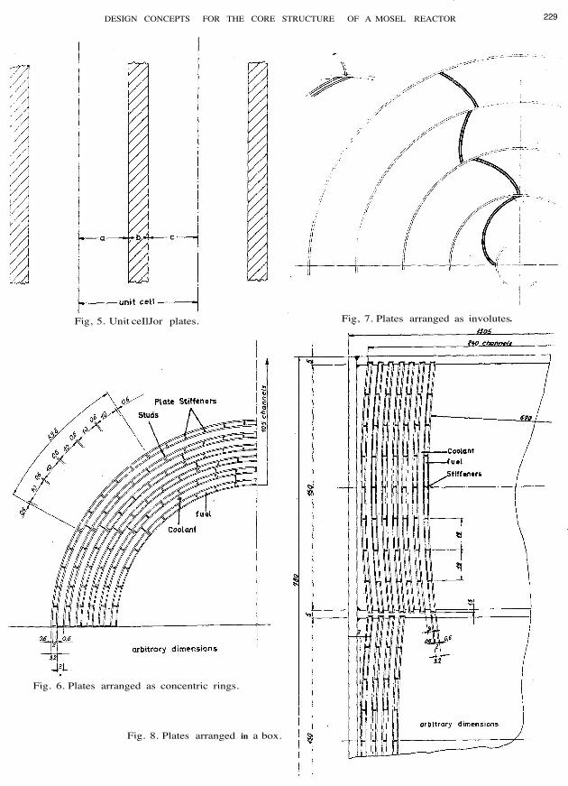
4.1. Plate designFig. 5 shows a unit cell based on a plate de-
sign. As shown, a is the half width of the fuelchannel, b is the thickness of the structural ma-terial, and c is the half width of the coolantchannel. The proportions of fuel, material andcoolant in the core are in the ratio of a:b:c. (Inreality a correction must be made to account forsupport structures about every 20 mm.Plate type core designs can involve a) concen-
tric rings, b) spirals, c) involutes, d) plates.Some features of these type designs are dis-cussed below.a) Concentric rings, shown in fig. 6, are ad-

228 P. R. KASTEN et al.
Fig. 4, Core built in parts, enables different combinations of basic elements.
vantageous in view of resistance to forces In-
duced by pressure, but the diameter of the coremust be kept small, because otherwise ratherthick walls are needed for the outer rings. Animportant difficulty is the required arrangementof the separate fuel and coolant streams with re-spect to inlet and outlet.b) Spiral heat exchangers are used in chemi-
cal industry. They are easy to manufacture, butwhen pressure is applied, they tend to distort.Control of flow can be applied relatively easy, if
the fuel stream is fed in at the center it may flo\\out at the edge. Coolant flow in this schemEwould be axial and perpendicular to fuel flow.c) Involute type designs, as indicated in fig, 7.
permit a constant distance to be maintained be-tween curved surface; also they can carry partof the forces induced by pressure. Difficultiesare associated with the proper design of inletand outlet flow streams from section to section.d) Plates arranged in square or other regular
geometries have certain advantages. Plates suit
DESIGN CONCEPTS FOR THE CORE STRUCTURE OF A MOSEL REACTOR 229
Fig, 5. Unit ceIlJor plates.
Fig. 6. Plates arranged as concentric rings.
Fig. 8. Plates arranged in a box.
Fig, 7. Plates arranged as involutes

230 P. R, KASTEN et al.
Fig. 9. Plates arranged hexagonally.
regular polygonal forms perfectly, as illustratedin figs. 8 and 9, in addition, they are easy to ar-range. An important advantage of plates lies intheir ability to absorb any bending energy on thecontainer walls induced by pressure differen-tials, thus avoiding a thick container wall. Theplates can be arranged perpendicular to the con-tainer wall and forces tending to bend the con-tainer wall outwards are taken up in the plane ofthe plates. Tensile stress induced thereby are
easier to handle than bending stresses. An ar-rangement of plates permits low volume fractionstructure in the core. Also, as indicated infig. 4, outer plates may be used as a fuel dis-tributor (fig. 11).
4.2. Tube designsTubes are more stable than plates and are
thus more able to withstand forces induced bypressure differentials. A difficulty with the use

DESIGN CONCEPTS FOR THE CORE STRUCTURE OF A MOSEL REACTOR
Fig. 10. Pipes connected in a tube sheet (fuel entry and exit not shown).
231
of tubes is associated with proper arrangementof the streams of fuel and coolant. It seems rea-sonable to contain the fuel inside the tubes to en-able flow control and allow a possible shut off ofa single tube in case of a leak. If the tubes areconnected by means of a tube sheet, as shown in
fig. 10, proper flow of coolant appears difficultto obtain. If the coolant stream is introducedperpendicular to the fuel tubes, as it is done inordinary heat exchangers, this leads to coolantflow distribution favouring the outer regions ofthe core. Since power density in general is high-

232 P ..R. KASTEN et al.
Fig. 11. Section showing container plate arranged as fuel distributor.
est in the core center, the associated high tem-peratures may require a non-uniform tubespac-ing and/or size in the core region.Another possibility of arranging the tubes
would be to connect several tubes to a distributorpipe, which acts as a manifold (as in fig. 2). Suchan arrangement would also permit various fuelconcentrations to be present within the core re-gion.
6. CONCLUSION
There appear to be a number of core designswhich are capable of satisfying the requirementsof a MOSEL-type reactor. Some of these wouldpermit the core to be built up from modularunits, thus enabling exchange of part of the corein caHe of failure.The choice between the use of plates and tubes
depends primarily upon fabrication ability andthe mechanical and physical properties of thecore structure. In a following article it is shownthat plate designs lead to some thermodynamicaland nuclear advantages. Tube designs appearadvantageous relative to stress considerations.Plate designs appear advantageous with regard
to arrangement of the flow of the fuel ana COOl-ant. A disadvantage of tube designs is associatedwith the use of a tube sheet or some other ar-rangement requiring relatively large amounts ofstructural material. Also, use of tubes requiresa wall between core and blanket that is capableof carrying pressure differential between the tworegions. Adciitional construction material in thecore leads to increased neutron losses and lowerbreeding ratios.
It appears that a plate-type design involvingregular polygons facilitates fluid flow patternsand flow control. At the same time, the amountof structural material required is relatively low,which is an important factor when criticality isachieved in the heat exchange region.
REFERENCES
1. P. R. Kasten, The MOSE L-reactor-concept, ThirdIntern, Conf. on the Peaceful Uses of Atomic Ener-gy, Geneva 1964, A Conf. 28/P /538.
2. P. R. Kasten, Eine Bewertung von Thorium-Brenn-stoffkreisHiufen, Kernforschungsanlage JUlich, Sep-tember 1964.
3, P.R.Kasten, Das MOSEL-Reaktor-Konzept, Atom-praxis 10 (1964),