Design concepts for the Cherenkov Telescope Array …...Exp Astron (2011) 32:193–316 DOI...
124
Exp Astron (2011) 32:193–316 DOI 10.1007/s10686-011-9247-0 ORIGINAL ARTICLE Design concepts for the Cherenkov Telescope Array CTA: an advanced facility for ground-based high-energy gamma-ray astronomy The CTA Consortium Received: 26 November 2010 / Accepted: 21 July 2011 / Published online: 23 November 2011 © The Author(s) 2011. This article is published with open access at Springerlink.com Abstract Ground-based gamma-ray astronomy has had a major breakthrough with the impressive results obtained using systems of imaging atmospheric Cherenkov telescopes. Ground-based gamma-ray astronomy has a huge po- tential in astrophysics, particle physics and cosmology. CTA is an international initiative to build the next generation instrument, with a factor of 5–10 improvement in sensitivity in the 100 GeV–10 TeV range and the extension to energies well below 100 GeV and above 100 TeV. CTA will consist of two arrays (one in the north, one in the south) for full sky coverage and will be operated as open observatory. The design of CTA is based on currently available technology. This document reports on the status and presents the major design concepts of CTA. Keywords Ground based gamma ray astronomy · Next generation Cherenkov telescopes · Design concepts 1 Executive summary The present generation of imaging atmospheric Cherenkov telescopes (H.E.S.S., MAGIC and VERITAS) has in recent years opened the realm of Contact: W. Hofmann ([email protected]), M. Martínez ([email protected]), CTA Project Office, Landessternwarte, Universität Heidelberg, Königstuhl, 69117 Heidelberg, Germany. The full author list and affiliations are given at the end of the paper. The CTA Consortium URL: http://www.cta-observatory.org e-mail: [email protected]
Transcript of Design concepts for the Cherenkov Telescope Array …...Exp Astron (2011) 32:193–316 DOI...
Exp Astron (2011) 32:193–316DOI 10.1007/s10686-011-9247-0
ORIGINAL ARTICLE
Design concepts for the Cherenkov Telescope ArrayCTA: an advanced facility for ground-basedhigh-energy gamma-ray astronomy
The CTA Consortium
Received: 26 November 2010 / Accepted: 21 July 2011 / Published online: 23 November 2011© The Author(s) 2011. This article is published with open access at Springerlink.com
Abstract Ground-based gamma-ray astronomy has had a major breakthroughwith the impressive results obtained using systems of imaging atmosphericCherenkov telescopes. Ground-based gamma-ray astronomy has a huge po-tential in astrophysics, particle physics and cosmology. CTA is an internationalinitiative to build the next generation instrument, with a factor of 5–10improvement in sensitivity in the 100 GeV–10 TeV range and the extensionto energies well below 100 GeV and above 100 TeV. CTA will consist oftwo arrays (one in the north, one in the south) for full sky coverage and willbe operated as open observatory. The design of CTA is based on currentlyavailable technology. This document reports on the status and presents themajor design concepts of CTA.
Keywords Ground based gamma ray astronomy ·Next generation Cherenkov telescopes · Design concepts
1 Executive summary
The present generation of imaging atmospheric Cherenkov telescopes(H.E.S.S., MAGIC and VERITAS) has in recent years opened the realm of
Contact: W. Hofmann ([email protected]), M. Martínez ([email protected]),CTA Project Office, Landessternwarte, Universität Heidelberg, Königstuhl,69117 Heidelberg, Germany.
The full author list and affiliations are given at the end of the paper.
The CTA ConsortiumURL: http://www.cta-observatory.orge-mail: [email protected]
194 Exp Astron (2011) 32:193–316
ground-based gamma ray astronomy for energies above a few tens of GeV. TheCherenkov Telescope Array (CTA) will explore in depth our Universe in veryhigh energy gamma-rays and investigate cosmic processes leading to relativisticparticles, in close cooperation with observatories of other wavelength rangesof the electromagnetic spectrum, and those using cosmic rays and neutrinos.
Besides guaranteed high-energy astrophysics results, CTA will have a largediscovery potential in key areas of astronomy, astrophysics and fundamentalphysics research. These include the study of the origin of cosmic rays and theirimpact on the constituents of the Universe through the investigation of galacticparticle accelerators, the exploration of the nature and variety of black holeparticle accelerators through the study of the production and propagation ofextragalactic gamma rays, and the examination of the ultimate nature of matterand of physics beyond the Standard Model through searches for dark matterand the effects of quantum gravity.
With the joining of the US groups of the Advanced Gamma-ray ImagingSystem (AGIS) project, and of the Brazilian and Indian groups in Spring 2010,and with the strong Japanese participation, CTA represents a genuinely world-wide effort, extending well beyond its European roots.
CTA will consist of two arrays of Cherenkov telescopes, which aim to:(a) increase sensitivity by another order of magnitude for deep observationsaround 1 TeV, (b) boost significantly the detection area and hence detectionrates, particularly important for transient phenomena and at the highestenergies, (c) increase the angular resolution and hence the ability to resolvethe morphology of extended sources, (d) provide uniform energy coveragefor photons from some tens of GeV to beyond 100 TeV, and (e) enhance thesky survey capability, monitoring capability and flexibility of operation. CTAwill be operated as a proposal-driven open observatory, with a Science DataCentre providing transparent access to data, analysis tools and user training.
To view the whole sky, two CTA sites are foreseen. The main site will be inthe southern hemisphere, given the wealth of sources in the central region ofour Galaxy and the richness of their morphological features. A second comple-mentary northern site will be primarily devoted to the study of Active GalacticNuclei (AGN) and cosmological galaxy and star formation and evolution. Theperformance and scientific potential of arrays of Cherenkov telescopes havebeen studied in significant detail, showing that the performance goals canbe reached. What remains to be decided is the exact layout of the telescopearray. Ample experience exists in constructing and operating telescopes of the12-m class (H.E.S.S., VERITAS). Telescopes of the 17-m class are operating(MAGIC) and one 28-m class telescope is under construction (H.E.S.S. II).These telescopes will serve as prototypes for CTA. The structural and opticalproperties of such telescopes are well understood, as many have been builtfor applications from radio astronomy to solar power installations. The fastelectronics needed in gamma ray astronomy to capture the nanosecond-scaleCherenkov pulses have long been mastered, well before such electronicsbecame commonplace with the Gigahertz transmission and processing usedtoday in telephony, internet, television, and computing.
Exp Astron (2011) 32:193–316 195
The extensive experience of members of the consortium in the area ofconventional photomultiplier tubes (PMTs) provides a solid foundation forthe design of cameras with an optimal cost/performance ratio. Consequently,the base-line design relies on conventional PMTs. Advanced photon detectorswith improved quantum efficiency are under development and test and maywell be available when the array is constructed. In short, all the technicalsolutions needed to carry out this project exist today. The main challenge liesin the industrialisation of all aspects of the production and the exploitation ofeconomies of scale.
Given the large amounts of data recorded by the instrument and producedby computer simulations of the experiment, substantial efforts in e-scienceand grid computing are envisaged to enable efficient data processing. Someof the laboratories involved in CTA are Tier 1 and 2 centres on the LHCcomputing grid and the Cosmogrid. Simulation and analysis packages for CTAare developed for the grid. The consortium has set up a CTA-Virtual Organi-sation within the EGEE project (Enabling Grids for E-sciencE; funded by theEuropean Union) for use of grid infrastructure and the sharing of computingresources, which will facilitate worldwide collaboration for simulations and theprocessing and analysis of scientific data.
Unlike current ground-based gamma-ray instruments, CTA will be anopen observatory, with a Science Data Centre (SDC) which provides pre-processed data to the user, as well as the tools necessary for the most commonanalyses. The software tools will provide an easy-to-use and well-definedaccess to data from this unique observatory. CTA data will be accessiblethrough the Virtual Observatory, with varying interfaces matched to differentlevels of expertise. The required toolkit is being developed by partners withexperience in SDC management from, for example, the INTEGRAL spacemission.
Experiments in astroparticle physics have proven to be an excellent train-ing ground for young scientists, providing a highly interdisciplinary workenvironment with ample opportunities to acquire not only physics skills butalso to learn data processing and data mining techniques, programming ofcomplex control and monitoring systems and design of electronics. Further,the environment of the large multi-national CTA Collaboration, workingacross international borders, ensures that presentation skills, communicationability and management and leadership proficiency are enhanced. Youngscientists frequently participate in outreach activities and, thus, hone alsotheir skills in this increasingly important area. With its training and mo-bility opportunities for young scientists, CTA will have a major impact onsociety.
Outreach activities will be an important part of the CTA operation. Lecturesand demonstrations augmented by web-based non-expert tools for viewingCTA data will be offered to pupils and lay audiences. Particularly interestingobjects will be featured on the CTA web pages, along the lines of the “Sourceof the Month” pages of the H.E.S.S. collaboration. CTA is expected tomake highly visible contributions towards popularising science and generating
196 Exp Astron (2011) 32:193–316
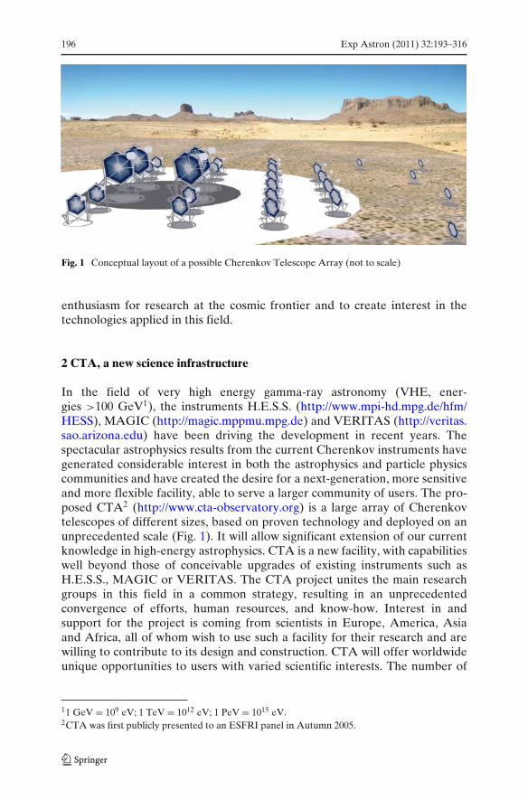
Fig. 1 Conceptual layout of a possible Cherenkov Telescope Array (not to scale)
enthusiasm for research at the cosmic frontier and to create interest in thetechnologies applied in this field.
2 CTA, a new science infrastructure
In the field of very high energy gamma-ray astronomy (VHE, ener-gies >100 GeV1), the instruments H.E.S.S. (http://www.mpi-hd.mpg.de/hfm/HESS), MAGIC (http://magic.mppmu.mpg.de) and VERITAS (http://veritas.sao.arizona.edu) have been driving the development in recent years. Thespectacular astrophysics results from the current Cherenkov instruments havegenerated considerable interest in both the astrophysics and particle physicscommunities and have created the desire for a next-generation, more sensitiveand more flexible facility, able to serve a larger community of users. The pro-posed CTA2 (http://www.cta-observatory.org) is a large array of Cherenkovtelescopes of different sizes, based on proven technology and deployed on anunprecedented scale (Fig. 1). It will allow significant extension of our currentknowledge in high-energy astrophysics. CTA is a new facility, with capabilitieswell beyond those of conceivable upgrades of existing instruments such asH.E.S.S., MAGIC or VERITAS. The CTA project unites the main researchgroups in this field in a common strategy, resulting in an unprecedentedconvergence of efforts, human resources, and know-how. Interest in andsupport for the project is coming from scientists in Europe, America, Asiaand Africa, all of whom wish to use such a facility for their research and arewilling to contribute to its design and construction. CTA will offer worldwideunique opportunities to users with varied scientific interests. The number of
11 GeV = 109 eV; 1 TeV = 1012 eV; 1 PeV = 1015 eV.2CTA was first publicly presented to an ESFRI panel in Autumn 2005.
Exp Astron (2011) 32:193–316 197
in particular young scientists working in the still evolving field of gamma-rayastronomy is growing at a steady rate, drawing from other fields such as nuclearand particle physics. In addition, there is increased interest by other parts ofthe astrophysical community, ranging from radio to X-ray and satellite-basedgamma-ray astronomers. CTA will, for the first time in this field, provideopen access via targeted observation proposals and generate large amounts ofpublic data, accessible using Virtual Observatory tools. CTA aims to becomea cornerstone in a networked multi-wavelength, multi-messenger explorationof the high-energy non-thermal universe.
3 The science case for CTA
3.1 Science motivation in a nutshell
3.1.1 Why observing in gamma-rays?
Radiation at gamma-ray energies differs fundamentally from that detected atlower energies and hence longer wavelengths: GeV to TeV gamma-rays cannotconceivably be generated by thermal emission from hot celestial objects. Theenergy of thermal radiation reflects the temperature of the emitting body,and apart from the Big Bang there is and has been nothing hot enough toemit such gamma-rays in the known Universe. Instead, we find that high-energy gamma-rays probe a non-thermal Universe, where other mechanismsallow the concentration of large amounts of energy onto a single quantum ofradiation. In a bottom-up fashion, gamma-rays can be generated when highlyrelativistic particles—accelerated for example in the gigantic shock waves ofstellar explosions—collide with ambient gas, or interact with photons andmagnetic fields. The flux and energy spectrum of the gamma-rays reflects theflux and spectrum of the high-energy particles. They can therefore be usedto trace these cosmic rays and electrons in distant regions of our own Galaxyor even in other galaxies. High-energy gamma-rays can also be produced ina top-down fashion by decays of heavy particles such as hypothetical darkmatter particles or cosmic strings, both of which might be relics of the BigBang. Gamma-rays therefore provide a window on the discovery of the natureand constituents of dark matter.
High-energy gamma-rays, as argued above, can be used to trace the pop-ulations of high-energy particles in distant regions of our own or in othergalaxies. Meandering in interstellar magnetic fields, cosmic rays will usuallynot reach Earth and thus cannot be observed directly. Those which do arrivehave lost all directional information and cannot be used to pinpoint theirsources, except for cosmic-rays of extreme energy >1018 eV. However, suchhigh-energy particle populations are an important aspect of the dynamics ofgalaxies. Typically, the energy content in cosmic rays equals the energies inmagnetic fields or in thermal radiation. The pressure generated by high-energyparticles drives galactic outflows and helps balance the gravitational collapse
198 Exp Astron (2011) 32:193–316
of galactic disks. Astronomy with high-energy gamma-rays is so far the onlyway to directly probe and image the cosmic particle accelerators responsiblefor these particle populations, in conjunction with studies of the synchrotronradiation resulting form relativistic electrons moving in magnetic fields andgiving rise to non-thermal radio and X-ray emission.
3.1.2 A f irst glimpse of the astrophysical sources of gamma-rays
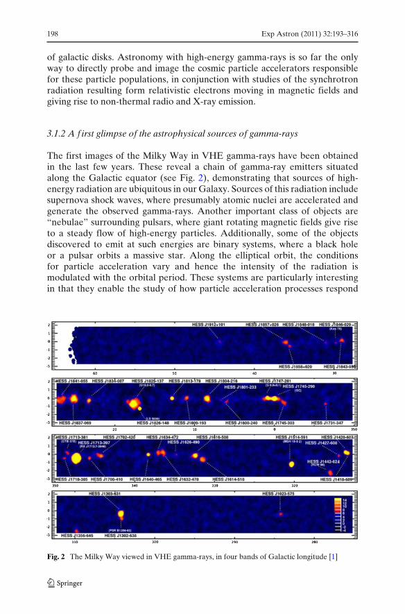
The first images of the Milky Way in VHE gamma-rays have been obtainedin the last few years. These reveal a chain of gamma-ray emitters situatedalong the Galactic equator (see Fig. 2), demonstrating that sources of high-energy radiation are ubiquitous in our Galaxy. Sources of this radiation includesupernova shock waves, where presumably atomic nuclei are accelerated andgenerate the observed gamma-rays. Another important class of objects are“nebulae” surrounding pulsars, where giant rotating magnetic fields give riseto a steady flow of high-energy particles. Additionally, some of the objectsdiscovered to emit at such energies are binary systems, where a black holeor a pulsar orbits a massive star. Along the elliptical orbit, the conditionsfor particle acceleration vary and hence the intensity of the radiation ismodulated with the orbital period. These systems are particularly interestingin that they enable the study of how particle acceleration processes respond
Fig. 2 The Milky Way viewed in VHE gamma-rays, in four bands of Galactic longitude [1]
Exp Astron (2011) 32:193–316 199
to varying ambient conditions. One of several surprises was the discovery of“dark sources”, objects which emit VHE gamma rays, but have no obviouscounterpart in other wavelength regimes. In other words, there are objects inthe Galaxy which might in fact be only detectable in high-energy gamma-rays.Beyond our Galaxy, many extragalactic sources of high-energy radiation havebeen discovered, located in active galaxies, where a super-massive black holeat the centre of the galaxy is fed by a steady stream of gas and is releasingenormous amounts of energy. Gamma-rays are believed to be emitted fromthe vicinity of these black holes, allowing the study of the processes occurringin this violent and as yet poorly understood environment.
3.1.3 Cherenkov telescopes
The recent breakthroughs in VHE gamma-ray astronomy were achieved withground-based Cherenkov telescopes. When a VHE gamma-ray enters theatmosphere, it interacts with atmospheric nuclei and generates a shower ofsecondary electrons, positrons and photons. Moving through the atmosphereat speeds higher than the speed of light in air, these electrons and positronsemit a beam of bluish light, the Cherenkov light. For near vertical showers thisCherenkov light illuminates a circle with a diameter of about 250 m on theground. For large zenith angles the area can increase considerably. This lightcan be captured with optical elements and be used to image the shower, whichvaguely resembles a shooting star. Reconstructing the shower axis in space andtracing it back onto the sky allows the celestial origin of the gamma-ray to bedetermined. Measuring many gamma-rays enables an image of the gamma-raysky, such as that shown in Fig. 2, to be created. Large optical reflectors withareas in the 100 m2 range and beyond are required to collect enough light,and the instruments can only be operated in dark nights at clear sites. WithCherenkov telescopes, the effective area of the detector is about the size ofthe Cherenkov pool at ground. As this is a circle with 250-m diameter thisis about 105× larger than the size that can be achieved with satellite-baseddetectors. Therefore much lower fluxes at higher energies can be investigatedwith Cherenkov Telescopes, enabling the study of short time scale variability.
The Imaging Atmospheric Cherenkov Technique was pioneered by theWhipple Collaboration in the United States. After more than 20 years ofdevelopment, the Crab Nebula, the first source of VHE gamma-rays, wasdiscovered in 1989. The Crab Nebula is among the strongest sources of veryhigh energy gamma-rays, and is often used as a “standard candle”. Moderninstruments, using multiple telescopes to track the cascades from differentperspectives and employing fine-grained photon detectors for improved imag-ing, can detect sources down to 1% of the flux of the Crab Nebula. Finely-pixellated imaging was first employed in the French CAT telescope [2], andthe use of “stereoscopic” telescope systems to provide images of the cascadefrom different viewing points was pioneered by the European HEGRA IACTsystem [3]. For summaries of the achievements in recent years and the sciencecase for a next-generation very high energy gamma ray observatory see [4–8].
200 Exp Astron (2011) 32:193–316
In March 2007, the High Energy Stereoscopic System (H.E.S.S.) projectwas awarded the Descartes Research Prize of the European Commissionfor offering “A new glimpse at the highest-energy Universe”. Together withthe instruments MAGIC and VERITAS (in the northern hemisphere) andCANGAROO (in the southern hemisphere), a new wavelength domain wasopened for astronomy, the domain of very high energy gamma-rays withenergies between about 100 GeV and about 100 TeV, energies which are amillion million times higher than the energy of visible light.
At lower energies, in the GeV domain, the launch of a new generationof gamma-ray telescopes (like AGILE, but in particular Fermi, which waslaunched in 2008) has opened a new era in gamma-ray discoveries [9]. TheLarge Area Telescope (LAT), the main instrument onboard Fermi, is sensitiveto gamma-rays with energies in the range from 20 MeV to about 100 GeV. Theenergy range covered by CTA will smoothly connect to that of Fermi-LATand overlap with that of the current generation of ground based instrumentsand extends to the higher energies, while providing an improvement in bothsensitivity and angular resolution.
3.2 The CTA science drivers
The aims of the CTA can be roughly grouped into three main themes, servingas key science drivers:
1. Understanding the origin of cosmic rays and their role in the Universe2. Understanding the nature and variety of particle acceleration around black
holes3. Searching for the ultimate nature of matter and physics beyond the Stan-
dard Model
Theme 1 comprises the study of the physics of galactic particle accelerators,such as pulsars and pulsar wind nebulae, supernova remnants, and gamma-ray binaries. It deals with the impact of the accelerated particles on theirenvironment (via the emission from particle interactions with the interstellarmedium and radiation fields), and the cumulative effects seen at various scales,from massive star forming regions to starburst galaxies.
Theme 2 concerns particle acceleration near super-massive and stellar-sizedblack holes. Objects of interest include microquasars at the Galactic scale, andblazars, radio galaxies and other classes of AGN that can potentially be studiedin high-energy gamma rays. The fact that CTA will be able to detect a largenumber of these objects enables population studies which will be a major stepforward in this area. Extragalactic background light (EBL), Galaxy clustersand Gamma Ray Burst (GRB) studies are also connected to this field.
Finally, Theme 3 covers what can be called “new physics”, with searchesfor dark matter through possible annihilation signatures, tests of Lorentzinvariance, and any other observational signatures that may challenge ourcurrent understanding of fundamental physics.
CTA will be able to generate significant advances in all these areas.
Exp Astron (2011) 32:193–316 201
3.3 Details of the CTA science case
We conclude this chapter with a few examples of physics issues that could besignificantly advanced with an instrument like CTA. The list is certainly notexhaustive. The physics of the CTA is being explored in detail by many sci-entists and their findings indicate the huge potential for numerous interestingdiscoveries with CTA.
3.3.1 Cosmic ray origin and acceleration
A tenet of high-energy astrophysics is that cosmic rays (CRs) are acceleratedin the shocks of supernova explosions. However, while particle acceleration upto energies well beyond 1014 eV has now clearly been demonstrated with thecurrent generation of instruments, it is by no means proven that supernovaeaccelerate the bulk of cosmic rays. The large sample of supernovae which willbe observable with CTA—in some scenarios several hundreds of objects—and in particular the increased energy coverage at lower and higher energies,will allow sensitive tests of acceleration models and determination of theirparameters. Improved angular resolution (arcmin) will help to resolve finestructures in supernova remnants which are essential for the study of particleacceleration and particle interactions. Pulsar wind nebulae surrounding thepulsars (created in supernova explosions) are another abundant source ofhigh-energy particles, including possibly high-energy nuclei. Energy conver-sion within pulsar winds and the interaction of the wind with the ambientmedium and the surrounding supernova shell challenge current ideas in plasmaphysics.
The CR spectrum observed near the Earth can be described by a purepower law up to an energy of a few PeV, where it slightly steepens. Thefeature is called the “knee”. The absence of other features in the spectrumsuggests that, if supernova remnants (SNRs) are the sources of galactic CRs,they must be able to accelerate particles at least up to the knee. For thisto happen, the acceleration in diffusive shocks has to be fast enough forparticles to reach PeV energies before the SNR enters the Sedov phase,when the shock slows down and consequently becomes unable to confinethe highest energy CRs [10] Since the initial free expansion velocity of SNRsdoes not vary much from object to object, only the amplification of magneticfields can increase the acceleration rate to the required level. Amplificationfactors of 100–1,000 compared to the interstellar medium value and smalldiffusion coefficients are needed [11]. The non-linear theory of diffusive shockacceleration suggests that such an amplification of the magnetic field mightbe induced by the CRs themselves, and high resolution X-ray observations ofSNR shocks seem to support this scenario, though their interpretation is de-bated. Thus, an accurate determination of the intensity of the magnetic field atthe shock is of crucial importance for disentangling the origin of the observedgamma-ray emission and understanding the way diffusive shock accelerationworks.
202 Exp Astron (2011) 32:193–316
Even if a SNR can be detected by Cherenkov telescopes during a significantfraction of its lifetime (up to several 104 years), it can make 1015 eV CRs onlyfor a much shorter time (several hundred years), due to the rapid escape ofPeV particles from the SNR. This implies that the number of SNRs whichhave currently a gamma-ray spectrum extending up to hundreds of TeV isvery roughly of the order of ∼10. The actual number of detectable objectswill depend on the distance and on the density of the surrounding interstellarmedium. The detection of such objects (even a few of them) would beextremely important, as it would be clear evidence for the acceleration of CRsup to PeV energies in SNRs. A sensitive scan of the galactic plane with CTAwould be an ideal way of searching for these sources. In general, the spectra ofradiating particles (both electrons and protons) and therefore also the spectraof gamma-ray radiation, should show characteristic curvature, reflecting ac-celeration at CR modified shocks. However, to see such curvature, one needsa coverage of a few decades in energy, far from the cutoff region. CTA willprovide this coverage. If the general picture of SNR evolution described aboveis correct, the position of the cutoff in the gamma-ray spectrum depends on theage of the SNR and on the magnetic field at the shock. A study of the numberof objects detected as a function of the cutoff energy will allow tests of thishypothesis and constraints to be placed on the physical parameters of SNRs,in particular of the magnetic field strength.
CTA offers the possibility of real breakthroughs in the understanding ofcosmic rays; as there is the potential to directly observe their diffusion (see,e.g., [12]) The presence of a massive molecular cloud located in the proximityof a SNR (or any kind of CR accelerator) provides a thick target for CRhadronic interactions and thus enhances the gamma-ray emission. Hence,studies of molecular clouds in gamma-rays can be used to identify the siteswhere CRs are accelerated. While travelling from the accelerator to the target,the spectrum of cosmic rays is a strong function of time, distance to the source,and the (energy-dependent) diffusion coefficient. Depending on the values ofthese parameters varying proton, and therefore gamma-ray, spectra may beexpected. CTA will allow the study of emission depending on these threequantities, which is impossible with current experiments. A determination,with high sensitivity, of spatially resolved gamma-ray sources related to thesame accelerator would lead to the experimental determination of the localdiffusion coefficient and/or the local injection spectrum of cosmic rays. Also,the observation of the penetration of cosmic rays into molecular clouds will bepossible. If the diffusion coefficient inside a cloud is significantly smaller thanthe average in the neighbourhood, low energy cosmic rays cannot penetratedeep into the cloud, and part of the gamma-ray emission from the cloud issuppressed, with the consequence that its gamma-ray spectrum appears harderthan the cosmic-ray spectrum.
Both of these effects are more pronounced in the denser central region ofthe cloud. Thus, with an angular resolution of the order of ≤1 arcmin one couldresolve the inner part of the clouds and measure the degree of penetration ofcosmic rays [13].
Exp Astron (2011) 32:193–316 203
More information on general aspects of cosmic rays and their relationship toVHE gamma observations is available in the review talks and papers presentedat the International Cosmic Ray Conference 2009 held in Łódz and the onlineproceedings are a good source of information [14].
3.3.2 Pulsar wind nebulae
Pulsar wind nebulae (PWNe) currently constitute the most populous classof identified Galactic VHE gamma-ray sources. As is well known, the CrabNebula is a very effective accelerator (shown by emission across more than 15decades in energy) but not an effective inverse Compton gamma-ray emitter.Indeed, we see gamma rays from the Crab because of its large spin-downpower (∼ 1038 erg s−1), although the gamma-ray luminosity is much less thanthe spin-down power of its pulsar. This can be understood as resulting froma large (mG) magnetic field, which also depends on the spin-down power. Aless powerful pulsar would imply a weaker magnetic field, which would allow ahigher gamma-ray efficiency (i.e. a more efficient sharing between synchrotronand inverse Compton losses). For instance, HESS J1825-137 has a similar TeVluminosity to the Crab, but a spin-down power that is 2 orders of magnitudesmaller, and its magnetic field has been constrained to be in the range of afew, instead of hundreds, of μG. The differential gamma-ray spectrum of thewhole emission region from the latter object has been measured over morethan two orders of magnitude, from 270 GeV to 35 TeV, and shows indicationsof a deviation from a pure power law that CTA could confirm and investigatein detail. Spectra have also been determined for spatially separated regionsof HESS J1825-137 [15]. Another example is HESS J1303-61 [16] The photonspectra in the different regions show a softening with increasing distance fromthe pulsar and therefore an energy dependent morphology. If the emissionis due to the inverse Compton effect, the pulsar power is not sufficient togenerate the gamma-ray luminosity, suggesting that the pulsar had a higherinjection power in the past. Is this common for other PWNe and what can thattell us about the evolution of pulsar winds? In the case of Vela X [17], the firstdetection of what appears to be a VHE inverse Compton peak in the spectralenergy distribution (SED) was found. Although a hadronic interpretation hasalso been put forward it is as yet unclear how large the contribution of ions tothe pulsar wind could be. CTA can be used to test leptonic vs. hadronic modelsof gamma-ray production in PWNe.
The return current problem for pulsars have not been solved to date, but ifwe detect a clear hadronic signal, this will show that ions are extracted fromthe pulsar surface, which may lead to a solution of the most fundamentalquestion in pulsar magnetospheric physics: how do we close the pulsar current?In systems where we see a clear leptonic signal, it is important to measurethe magnetisation (or “sigma”) parameter of the PWNe. Are the magneticfields and particles in these systems in equipartition (as in the Crab Nebula)or do have particle dominated winds? This will contribute significantly to theunderstanding of the magnetohydrodynamic flow in PWNe. Understanding
204 Exp Astron (2011) 32:193–316
the time evolution of the multi-wavelength synchrotron and inverse Compton(or hadronic) intensities is also an aim of CTA. Such evolutionary tracksare determined by the nature of the progenitor stellar wind, the propertiesof the subsequent composite SNR explosion and the surrounding interstellarenvironment. Finally, the sensitivity and angular resolution achievable withCTA will allow detailed multi-wavelength studies of large/close PWNe, and theunderstanding of particle propagation, the magnetic field profile in the nebula,and inter-stellar medium (ISM) feedback.
The evolution and structure of pulsar wind nebulae is discussed in a recentreview [18]. Many key implications for VHE gamma ray measurements, andan assessment of the current observations can be found in [19].
3.3.3 The galactic centre region
It is clear that the galactic centre region itself will be one of the prime sciencetargets for the next generation of VHE instruments [20, 21]. The galacticcentre hosts the nearest super-massive black hole, as well as a variety of otherobjects likely to generate high-energy radiation, including hypothetical dark-matter particles which may annihilate and produce gamma-rays. Indeed, thegalactic centre has been detected as a source of high-energy gamma-rays, andindications for high-energy particles diffusing away from the central source andinteracting with the dense gas clouds in the central region have been observed.In observations with improved sensitivity and resolution, the galactic centrecan potentially yield a variety of interesting results on particle acceleration andgamma-ray production in the vicinity of black holes, on particle propagationin central molecular clouds, and, possibly, on the detection of dark matterannihilation or decay.
The VHE gamma-ray view of the galactic centre region is dominated bytwo point sources, one coincident with a PWN inside SNR G0.9+0.1, and onecoincident with the super-massive black hole Sgr A* and another putativePWN (G359.95-0.04). After subtraction of these sources diffuse emission alongthe galactic centre ridge is visible, which shows two important features: itappears correlated with molecular clouds (as traced by the CS (1–0) line), andit exceeds by a factor of 3 to 9 the gamma-ray emission that would be producedif the same target material was exposed to the cosmic-ray environment in ourlocal neighbourhood. The striking correlation of diffuse gamma-ray emissionwith the density of molecular clouds within ∼150 pc of the galactic centrefavours a scenario in which cosmic rays interact with the cloud material andproduce gamma-rays via the decay of neutral pions. The differential gamma-ray flux is stronger and harder than expected from just “passive” exposureof the clouds to the average galactic cosmic ray flux, suggesting one or morenearby particle accelerators are present. In a first approach, the observedgamma-ray morphology can be explained by cosmic rays diffusing awayfrom an accelerator near the galactic centre into the surroundings. Adoptinga diffusion coefficient of D = O(1030) cm2/s, the lack of VHE gamma-rayemission beyond 150 pc in this model points to an accelerator age of no more
Exp Astron (2011) 32:193–316 205
than 104 years. Clearly, improved sensitivity and angular resolution wouldpermit the study of the diffusion process in great detail, including any possibleenergy dependence. An alternative explanation (which CTA will address) isthe putative existence of a number of electron sources (e.g. PWNe) along thegalactic centre ridge, correlated with the density of molecular clouds. Giventhe complexity and density of the source population in the galactic centreregion, CTA’s improved sensitivity and angular resolution is needed to mapthe morphology of the diffuse emission, and to test its hadronic or leptonicorigin.
CTA will also measure VHE absorption in the interstellar radiation field(ISRF). This is impossible for other experiments, like Fermi-LAT, as theirenergy coverage is too small, and very hard or perhaps impossible for currentair Cherenkov experiments, as they lack the required sensitivity. At 8 kpc dis-tance, VHE gamma-ray attenuation due to the CMB is negligible for energies<500 TeV. But the attenuation due to the ISRF (which has a comparablenumber density at wavelengths 20–300 μm) can produce absorption at about50 TeV [22]. Observation of the cutoff energy for different sources will provideindependent tests and constraints of ISRF models. CTA will observe sources atdifferent distances and thereby independently measure the absorption modeland the ISRF. Due to their smaller distances there is less uncertainty inidentifying intrinsic and extrinsic features in the spectrum than is the case forEBL studies.
3.3.4 Microquasars, gamma-ray, and X-ray binaries
Currently, a handful of VHE gamma-ray emitters are known to be binarysystems, consisting of a compact object, a neutron star or a black hole, orbitinga massive star. Whilst many questions on the gamma-ray emission from suchsystems are still open (in some cases it is not even clear if the energy sourceis a pulsar-driven nebula around a neutron star or accretion onto a blackhole) it is evident that they offer a unique chance to “experiment” withcosmic accelerators. Along the eccentric orbits of the compact objects, theenvironment (including the radiation field) changes, resulting in a periodicmodulation of the gamma-ray emission, allowing the study of how particleacceleration is affected by environmental conditions. Interestingly, the physicsof microquasars in our own Galaxy resembles the processes occurring aroundsuper-massive black holes in distant active galaxies, with the exception of themuch reduced time scales, providing insights in the emission mechanisms atwork. The following are key questions in this area which CTA will be ableto address, because of the extension of the accessible energy domain, theimprovement in sensitivity, and the superior angular resolution it provides:
(a) Studies of the formation of relativistic outf lows from highly magnetised,rotating objects. If gamma-ray binaries are pulsars, is the gamma-ray emis-sion coming mostly from processes within the pulsar wind zone or ratherfrom particles accelerated in the wind collision shock? Is the answer to
206 Exp Astron (2011) 32:193–316
this question a function of energy? What role do the inner winds play,particularly with regard to particle injection? Gamma-ray astronomy canprovide data that will help to answer these questions, but which will alsothrow light on the particle energy distribution within the pulsar wind zoneitself. Recent Fermi-LAT results on gamma-ray binaries, such as LS I +61303 and LS 5039 (which are found to be periodic at GeV and TeV ener-gies, although anti-correlated [23]), show the existence of a cutoff in theSED at a few GeV (a feature that was not predicted by any models). Thus,the large energy coverage of CTA is an essential prerequisite in disentan-gling of the pulsed and continuous components of the radiation and theexploration of the processes leading to the observed GeV–TeV spectraldifferences.
(b) Studies of the link between accretion and ejection around compact objectsand transient states associated with VHE emission. It is known that blackholes display different spectral states in X-ray emission, with transitionsbetween a low/hard state, where a compact radio jet is seen, to a high/softstate, where the radio emission is reduced by large factors or not de-tectable at all [24]. Are these spectral changes related to changes inthe gamma-ray emission? Is there any gamma-ray emission during non-thermal radio flares (with increased flux by up to a factor of 1,000)?Indeed, gamma-ray emission via the inverse Compton effect is expectedwhen flares occur in the radio to X-ray region, due to synchrotronradiation of relativistic electrons and radiative, adiabatic and energy-dependent escape losses in fast-expanding plasmoids (radio clouds). Canfuture gamma-ray observations put constraints on the magnetic fields inplasmoids?Continued observations of key objects (such as Cyg X-1) with the sensi-tivity of current instruments (using sub-arrays of CTA) can provide goodcoverage. Flares of less than 1 hour at a flux of 10% of the Crab could bedetected at the distance of the Galactic Centre. Hence variable sourcescould be monitored and triggers provided for observations with all CTAtelescopes or with other instruments. For short flares, energy coverage inthe 10–100 GeV band is not possible with current instruments (AGILEand Fermi-LAT lack sensitivity). Continuous coverage at higher energiesis also impossible, due to lack of sensitivity with the current generation ofImaging Atmospheric Cherenkov Telescopes (IACTs). CTA will provideimproved access to both regions.
(c) Collision of the jet with the ISM, as a non-variable source of gamma-ray emission. Improved angular resolution at high energies will pro-vide opportunities for the study of microquasars, particularly if theirjets contain a sizeable fraction of relativistic hadrons. While innerengines will still remain unresolved with future Cherenkov telescopearrays, microquasar jets and their interaction with the ISM might be-come resolvable, leading to the distinction of emission from the cen-tral object (which may be variable) and from the jet-ISM interaction(which may be stable). Microquasars, gamma-ray, and X-ray binaries,
Exp Astron (2011) 32:193–316 207
and high-energy aspects of astrophysical jets and binaries are discussedin [25].
3.3.5 Stellar clusters, star formation, and starburst galaxies
While the classical paradigm has supernova explosions as the dominant sourceof cosmic rays, it has been speculated that cosmic rays are also accelerated instellar winds around massive young stars before they explode as supernovae,or around star clusters [26]. Indeed, there is growing evidence from gamma-ray data for a population of sources related to young stellar clusters andenvironments with strong stellar winds. However, lack of sensitivity currentlyprevents the detailed study and clear identification of these sources of gammaradiation. CTA aims at a better understanding of the relationship betweenstar formation processes and gamma-ray emission. CTA can experimentallyestablish whether there is a direct correlation between star formation rateand gamma-ray luminosity when convection and absorption processes at thedifferent environments are taken into account. Both the VERITAS andH.E.S.S. arrays have done deep observations of the nearest starburst galaxies,and have found them to be emitting TeV gamma-rays at the limit of theirsensitivity. Future observations, with improved sensitivity at higher and lowerenergies, will reveal details of this radiation which in turn will help with anunderstanding of the spectra, provide constraints on the physical emissionscenarios and extend the study of the relationship between star formationprocesses and gamma-ray emission to extragalactic environments. A goodcompendium of the current status of this topic can be found in the proceedingsof a recent conference [27].
3.3.6 Pulsar physics
Pulsar magnetospheres are known to act as efficient cosmic accelerators, yetthere is no complete and accepted model for this acceleration mechanism,a process which involves electrodynamics with very high magnetic fields aswell as the effects of general relativity. Pulsed gamma-ray emission allows theseparation of processes occurring in the magnetosphere from the emission inthe surrounding nebula. That pulsed emission at tens of GeV can be detectedwith Cherenkov telescopes was recently demonstrated by MAGIC with theCrab pulsar [28] (and the sensitivity for pulsars with known pulse frequencyis nearly an order of magnitude higher than for standard sources). CurrentFermi-LAT results provide some support for models in which gamma-rayemission occurs far out in the magnetosphere, with reduced magnetic fieldabsorption (i.e. in outer gaps). In these models, exponential cut-offs in thespectral energy distribution are expected at a few GeV, which have alreadybeen found in several Fermi pulsars. To make further progress in understand-ing the emission mechanisms in pulsars it is necessary to study their radiationat extreme energies. In particular, the characteristics of pulsar emission in
208 Exp Astron (2011) 32:193–316
the GeV domain (currently best examined by the Fermi-LAT) and at VHEwill tell us more about the electrodynamics within their magnetospheres.Studies of interactions of magnetospheric particle winds with external ambientfields (magnetic, starlight, CMB) are equally vital. Between ∼10 GeV and∼50 GeV (where the LAT performance is limited) CTA, with a special low-energy trigger for pulsed sources, will allow a closer look at unidentifiedFermi sources and deeper analysis of Fermi pulsar candidates. Above 50 GeVCTA will explore the most extreme energetic processes in millisecond pulsars.The VHE domain will be particularly important for the study of millisecondpulsars, very much as the HE domain (with Fermi) is for classical pulsars.On the other hand, the high-energy emission mechanism from magnetars isessentially unknown. For magnetars, we do not expect polar cap emission.Due to the large magnetic field, all high-energy photons would be absorbed ifemitted close to the neutron star, i.e., CTA would be testing outer-gap models,especially if large X-ray flares are accompanied by gamma-emission.
CTA can study the GeV-TeV emission related to short-timescale pulsarphenomena, which is beyond the reach of currently working instruments.CTA can observe possible high-energy phenomena related to timing noise (inwhich the pulse phase and/or frequency of radio pulses drift stochastically) orto sudden increases in the pulse frequency (glitches) produced by apparentchanges in the momentum of inertia of neutron stars.
Periodicity measurements with satellite instruments, which require verylong integration times, may be compromised by such glitches, while CTA,with its much larger detection area and correspondingly shorter measurementtimes, is not.
A good compendium of the current status of this topic can be found in theproceedings and the talks presented at the “International Workshop on theHigh-Energy Emission from Pulsars and their Systems” [29].
3.3.7 Active galaxies, cosmic radiation f ields and cosmology
Active Galactic Nuclei (AGN) are among the largest storehouses of energyknown in our cosmos. At the intersection of powerful low-density plasmainflows and outflows, they offer excellent conditions for efficient particleacceleration in shocks and turbulences. AGN represent one third of the knownVHE gamma-ray sources, with most of the detected objects belonging to theBL Lac class. The fast variability of the gamma-ray flux (down to minutetime scales) indicates that gamma-ray production must occur close to theblack hole, assisted by highly relativistic motion resulting in time (Lorentz)contraction when viewed by an observer on Earth. Details of how these jets arelaunched or even the types of particles of which they consist are poorly known.Multi-wavelength observations with high temporal and spectral resolution canhelp to distinguish between different scenarios, but this is at the limit of thecapabilities of current instruments. The sensitivity of CTA, combined withsimultaneous observations in other wavelengths, will provide a crucial advancein understanding the mechanisms driving these sources.
Exp Astron (2011) 32:193–316 209
Available surveys of BL Lacs suffer several biases at all wavelengths, furthercomplicated by Doppler boosting effects and high variability. The big increaseof sensitivity of CTA will provide large numbers of VHE sources of differenttypes and opens the way to statistical studies of the VHE blazar and AGNpopulations. This will enable the exploration of the relation between differenttypes of blazars, and of the validity of unifying AGN schemes. The distributionin redshift of known and relatively nearby BL Lac objects peaks aroundz ∼ 0.3. The large majority of the population is found within z < 1, a rangeeasily accessible with CTA. CTA will therefore be able to analyse in detailblazar populations (out to z ∼ 2) and the evolution of AGN with redshift andto start a genuine “blazar cosmology”.
Several scenarios have been proposed to explain the VHE emission ofblazars.3 However, none of them is fully self-consistent, and the current dataare not sufficient to firmly rule out or confirm a particular mechanism. Inthe absence of a convincing global picture, a first goal for CTA will be toconstrain model-dependent parameters of blazars within a given scenario.This is achievable due to the wide energy range, high sensitivity and highspectral resolution of CTA combined with multi-wavelength campaigns. Thus,the physics of basic radiation models will be constrained by CTA, and some ofthe models will be ruled out. A second more difficult goal will be to distinguishbetween the different remaining options and to firmly identify the dominantradiation mechanisms. Detection of specific spectral features, breaks, cut-offs,absorption or additional components, would be greatly helpful for this. Therole of CTA as a timing explorer will be decisive for constraining both theradiative phenomena associated with, and the global geometry and dynamicsof, the AGN engine. Probing variability down to the shortest time scales willsignificantly constrain acceleration and cooling times, instability growth rates,and the time evolution of shocks and turbulences. For the brightest blazarflares, current instruments are able to detect variability on the scales of severalminutes. With CTA, such flares should be detectable within seconds, ratherthan minutes. A study of the minimum variability times of AGN with CTAwould allow the localisation of VHE emission regions (parsec distance scalesin the jet, the base of the jet, or the central engine) and would provide stringentconstraints on the emission mechanisms as well as the intrinsic time scaleconnected to the size of the central super-massive black hole.
Recently, radio galaxies have emerged as a new class of VHE emitting AGN[37]. Given the proximity of the sources and the larger jet angle to the line ofsight compared to BL Lac objects, the outer and inner kpc jet structures will be
3There are several clear cases of blazar SEDs where the X-ray peak and the γ -ray peak, with theircorrelated luminosity and spectral changes, are interpreted within a synchrotron-self-Compton(SSC) model [30] as the synchrotron and IC peak respectively, produced by a time-varyingpopulation of particles (e.g. [31, 32]). A variant of the Compton scenario considers that the softphotons produced externally to the jet may be more effective than the internal ones (externalCompton, EC, model; e.g. [33, 34]). Models based on hadronic acceleration (e.g. [35, 36]) can alsoreproduce the blazar SEDs and lightcurves.
210 Exp Astron (2011) 32:193–316
spatially resolved by CTA. This will allow precise location of the main emissionsite and searches for VHE radiation from large-scale jets and hot spots besidesthe central core and jets seen in very long baseline interferometry images.
The observation of VHE emission from distant objects and their surround-ings will also offer the unique opportunity to study extragalactic magneticfields at large distances. If the fields are large, an e+ e− pair halo forms aroundAGNs, which CTA, with its high sensitivity and extended field of view, shouldbe capable of detecting. For smaller magnetic field values, the effect of e+ e−pair formation along the path to the Earth is seen through energy-dependenttime-delays of variable VHE emission, which CTA with its excellent timeresolution will be ideally suited to measure.
CTA will also have the potential to deliver for the first time significantresults on extragalactic diffuse emission at VHE, and offers the possibilityof probing the integrated emission from all sources at these energies. Whilewell measured at GeV energies with the EGRET and Fermi-LAT instruments,the diffuse emission at VHE is extremely challenging to measure due to itsfaintness and the difficulty of adequately subtracting the background. Here,the improved sensitivity coupled with the large field of view puts detection inreach of CTA.
VHE gamma-rays traveling from remote sources interact with the EBL viae+ e− pair production and are absorbed. Studying such effects as a functionof the energy and redshift will provide unique information on the EBLdensity, and thereby on the history of the formation of stars and galaxies inthe Universe. This approach is complementary to direct EBL measurements,which are hampered by strong foreground emission from our planetary system(zodiacal light) and the Galaxy.
We anticipate that MAGIC II and H.E.S.S. II will at least double thenumber of detected sources, but this is unlikely to resolve the ambiguitybetween intrinsic spectral features and effects due to the EBL. It wouldstill be very difficult to extract spectral information beyond z > 0.5, if ourcurrent knowledge of the EBL is correct. Only CTA will be able to provide asufficiently large sample of VHE gamma-ray sources, and high-quality spectrafor individual objects. For many of the sources, the SED will be determined atGeV energies, which are much less affected by the absorption and, thus, moresuitable for the study of the intrinsic properties of the objects. We thereforeanticipate that with CTA it will be possible to make robust predictionsabout the intrinsic spectrum above 40–50 GeV, for individual sources and forparticular source classes.
The end of the dark ages of the Universe, the epoch of reionisation, is atopic of great interest [38]. Not (yet) fully accessible via direct observations,most of our knowledge comes from simulations and from integral observableslike the cosmic microwave background. The first (Population III) and secondgenerations of stars are natural candidates for being the source of reionisation.If the first stars are hot and massive, as predicted by simulations, their UVphotons emitted at z > 5 would be redshifted to the near infrared and couldleave a unique signature on the EBL spectrum. If the EBL contribution from
Exp Astron (2011) 32:193–316 211
lower redshift galaxies is sufficiently well known (for example, as derived fromsource counts) upper limits on the EBL density can be used to probe the prop-erties of early stars and galaxies. Combining detailed model calculations withredshift-dependent EBL density measurements could allow the probing of thereionisation/ionisation history of the Universe. A completely new wavelengthregion of the EBL will be opened up by observations of sources at very highredshifts (z > 5), which will most likely be gamma-ray bursts. According tohigh-redshift UV background models, consistent with our current knowledgeof cosmic reionisation, spectral cut-offs are expected in the few GeV to fewtens of GeV range at z > 5. Thus, CTA could have the unique potential toprobe cosmic reionisation models through gamma-ray absorption in high-zGRBs. We analyse the GRB prospects in more detail in the following.
A good compendium of the current state of this topic can be found inthe talks and the proceedings of the meeting, High-energy phenomena inrelativistic outflows II [39].
3.3.8 Gamma-ray bursts
Gamma-Ray Bursts are the most powerful explosions in the Universe, andare by far the most electromagnetically luminous sources known to us. Thepeak luminosity of GRBs, equivalent to the light from millions of galaxies,means they can be detected up to high redshifts, hence act as probes of thestar formation history and reionisation of the Universe. The highest measuredGRB redshift is z = 8.2 but GRBs have been observed down to z = 0.0085(the mean redshift is z ∼ 2.2). GRBs occur in random directions on the sky,briefly outshining the rest of the hard X-ray and soft gamma-ray sky, and thenfade from view. The rapid variability seen in gamma- and X-rays indicatesa small source size, which together with their huge luminosities and clearlynon-thermal spectrum (with a significant high-energy tail) require the emittingregion to move toward us with a very large bulk Lorentz factor of typically>100, sometimes as high as >1,000 [40–42].
Thus, GRBs are thought to be powered by ultra-relativistic jets producedby rapid accretion onto a newly formed stellar-mass black hole or a rapidlyrotating highly-magnetised neutron star (i.e. a millisecond magnetar). Theprompt gamma-ray emission is thought to originate from dissipation withinthe original outflow by internal shocks or magnetic reconnection events. Somelong duration GRBs are clearly associated with core-collapse supernovae oftype Ic (from very massive Wolf–Rayet stars stripped of their H and Heenvelope by strong stellar winds), while the progenitors of short GRBs aremuch less certain: the leading model involves the merger of two neutron starsor a neutron star and a black hole [43, 44].
Many of the details of GRB explosions remain unclear. Studying themrequires a combination of rapid observations to observe the prompt emissionbefore it fades, and a wide energy range to properly capture the spectralenergy distribution. Most recently, GRBs have been observed by the Swiftand Fermi missions, which have revealed an even more complex behaviour

212 Exp Astron (2011) 32:193–316
than previously thought, featuring significant spectral and temporal evolution.As yet, no GRB has been detected at energies >100 GeV due to the limitedsensitivity of current instruments and the large typical redshifts of theseevents. In just over a year of operation, the Fermi-LAT has detected emissionabove 10 GeV (30 GeV) from 4 (2) GRBs. In many cases, the LAT detectsemission >0.1 GeV for several hundred seconds in the GRB rest-frame. InGRB090902B a photon of energy ∼33.4 GeV was detected, which translatesto an energy of ∼94 GeV at its redshift of z = 1.822. Moreover, the observedspectrum is fairly hard up to the highest observed energies.
Extrapolating the Fermi spectra to CTA energies suggests that a goodfraction of the bright LAT GRBs could be detected by CTA even in ∼minuteobserving times, if it could be turned to look at the prompt emission fastenough. The faster CTA could get on target, the better the scientific return.Increasing the observation duty cycle by observing for a larger fraction of thelunar cycle and at larger zenith angles could also increase the return.
Detecting GRBs in the CTA energy range would greatly enhance ourknowledge of the intrinsic spectrum and the particle acceleration mechanismof GRBs, particularly when combined with data from Fermi and other obser-vatories. As yet it is unclear what the relative importance is of the various pro-posed emission processes, which divide mainly into leptonic (synchrotron andinverse-Compton, and in particular synchrotron-self-Compton) and hadronicprocesses (induced by protons or nuclei at very high energies which either ra-diate synchrotron emission or produce pions with subsequent electromagneticcascades). CTA may help to determine the identity of the distinct high-energycomponent that was observed so far in three out of the four brightest LATGRBs. The origin of the high-energy component may in turn shed light onthe more familiar lower-energy components that dominate at soft gamma-ray energies. The bulk Lorentz factor and the composition (protons, e+ e−pairs, magnetic fields) of the outflows are also highly uncertain and may beprobed by CTA. The afterglow emission which follows the prompt emissionis significantly fainter, but should also be detectable in some cases. Suchdetections would be expected from bright GRBs at moderate redshift, notonly from the afterglow synchrotron-self-Compton component, but perhapsalso from inverse-Compton emission triggered by bright, late (hundreds tothousands of seconds) flares that are observed in about half of all Swift GRBs.
The discovery space at high energies is large and readily accessible toCTA. The combination of GRBs being extreme astrophysical sources andcosmological probes make them prime targets for all high-energy experiments.With its large collecting area, energy range and rapid response, CTA is by farthe most powerful and suitable VHE facility for GRB research and will openup a new energy range for their study.
3.3.9 Galaxy clusters
Galaxy clusters are storehouses of cosmic rays, since all cosmic rays producedin the galaxies of the cluster since the beginning of the Universe will be

Exp Astron (2011) 32:193–316 213
confined there. Probing the density of cosmic rays in clusters via their gamma-ray emission thus provides a calorimetric measure of the total integrated non-thermal energy output of galaxies. Accretion/merger shocks outside clustergalaxies provide an additional source of high-energy particles. Emission fromgalaxy clusters is predicted at levels just below the sensitivity of currentinstruments [45].
Clusters of galaxies are the largest, gravitationally-bound objects in theUniverse. The observation of mainly radio (and in some cases X-ray) emissionproves the existence of non-thermal phenomena therein, but gamma-rays havenot yet been detected. A possible additional source of non-thermal radiationfrom clusters is the annihilation of dark matter (DM). The increased sensitivityof CTA will help to establish the DM signal, and CTA could possibly be thefirst instrument to map DM at the scale of galaxy clusters.
3.3.10 Dark matter and fundamental physics
The dominant form of matter in the Universe is the as yet unknown darkmatter, which is most likely to exist in the form of a new class of particles suchas those predicted in supersymmetric or extra dimensional extensions to thestandard model of particle physics. Depending on the model, these DM parti-cles can annihilate or decay to produce detectable Standard Model particles,in particular gamma-rays. Large dark matter densities due to the accumulationin gravitational potential wells leads to detectable fluxes, especially for anni-hilation, where the rate is proportional to the square of the density. CTA is adiscovery instrument with unprecedented sensitivity for this radiation and alsoan ideal tool to study the properties of the dark matter particles. If particlesbeyond the standard model are discovered (at the Large Hadron Collider or inunderground experiments), CTA will be able to verify whether they actuallyform the dark matter in the Universe. Slow-moving dark matter particles couldgive rise to a striking, almost mono-energetic photon emission. The discoveryof such line emission would be conclusive evidence for dark matter. CTAmight have the capability to detect gamma-ray lines even if the cross-sectionis loop-suppressed, which is the case for the most popular candidates of darkmatter, i.e. those inspired by the minimal supersymmetric extensions to thestandard model (MSSM) and models with extra dimensions, such as Kaluza-Klein theories. Line radiation from these candidates is not detectable by Fermi,H.E.S.S. II or MAGIC II, unless optimistic assumptions on the dark matterdensity distribution are made. Recent updates of calculations regarding thegamma-ray spectrum from the annihilation of MSSM dark matter indicate thepossibility of final-state contributions giving rise to distinctive spectral features(see the reviews in [46]).
The more generic continuum contribution (arising from pion production) ismore ambiguous but, with its curved shape, potentially distinguishable fromthe usual power-law spectra exhibited by known astrophysical sources.
Our galactic centre is one of the most promising regions to look for darkmatter annihilation radiation due to its predicted very high dark matter

214 Exp Astron (2011) 32:193–316
density. It has been observed by many experiments so far (e.g. H.E.S.S.,MAGIC and VERITAS) and high-energy gamma emission has been found.However, the identification of dark matter in the galactic centre is complicatedby the presence of many conventional source candidates and the difficultiesof modelling the diffuse gamma-ray background adequately. The angular andenergy resolution of CTA, as well as its enhanced sensitivity will be crucialto disentangling the different contributions to the radiation from the galacticcentre.
Other individual targets for dark matter searches are dwarf spheroidals anddwarf galaxies. They exhibit large mass-to-light ratios, and allow dark mattersearches with low astrophysical backgrounds. With H.E.S.S., MAGIC andFermi-LAT, some of these objects were observed and upper limits on darkmatter annihilation calculated, which are currently about an order of mag-nitude above the prediction of the most relevant cosmological models. CTAwill have good sensitivity for Weakly Interacting Massive Particle (WIMP)annihilation searches in the low and medium energy domains. An improve-ment in flux sensitivity of 1–2 orders of magnitude over current instrumentsis expected. Thus CTA will allow tests in significant regions of the MSSMparameter space.
Dark matter would also cause spectral and spatial signatures in extra-galactic and galactic diffuse emission. While the emissivity of conventionalastrophysical sources scale with the local matter density, the emissivity ofannihilating dark matter scales with the density squared, causing differencesin the small-scale anisotropy power spectrum of the diffuse emission.
Recent measurements of the positron fraction presented by the PAMELACollaboration [47] point towards a relatively local source of positrons andelectrons, especially if combined with the measurement of the e+ e− spectrumby Fermi-LAT [48]. The main candidates being put forward are either pul-sar(s) or dark matter annihilation. One way to distinguish between these twohypotheses is the spectral shape. The dark matter spectrum exhibits a suddendrop at an energy which corresponds to the dark matter particle mass, whilethe pulsar spectrum falls off more smoothly. Another hint is a small anisotropy,either in the direction of the galactic centre (for dark matter) or in the directionof the nearest mature pulsars. The large effective area of CTA, about six ordersof magnitudes larger than for balloon- and satellite-borne experiments, and thegreatly improved performance compared to existing Cherenkov observatories,might allow the measurement of the spectral shape and even the tiny dipoleanisotropy.
If the PAMELA result originated from dark matter, the DM particle’s masswould be >1 TeV/c2, i.e. large in comparison to most dark matter candidatesin MSSM and Kaluza-Klein theories. With its best sensitivity at 1 TeV, CTAwould be well suited to detect dark matter particles of TeV/c2 masses. The bestsensitivity of Fermi-LAT for dark matter is at masses of the order of 10–100GeV/c2.
Electrons and positrons originating from dark matter annihilation or decayalso produce synchrotron radiation in the magnetic fields present in the dense
Exp Astron (2011) 32:193–316 215
regions where the annihilation might take place. This opens up the possibilityof multi-wavelength observations. Regardless of the wavelength domain inwhich dark matter will be detectable using present or future experiments, itis evident that CTA will provide coverage for the highest-energy part of themulti-wavelength spectrum necessary to pinpoint, discriminate and study darkmatter indirectly.
Due to their extremely short wavelength and long propagation distances,very high-energy gamma-rays are sensitive to the microscopic structure ofspace-time. Small-scale perturbations of the smooth space-time continuumshould manifest themselves in an (extremely small) energy dependence of thespeed of light. Such a violation of Lorentz invariance, on which the theory ofspecial relativity is based, is present in some quantum gravity (QG) models.Burst-like events in which gamma-rays are produced, e.g. in active galaxies,allow this energy-dependent dispersion of gamma-rays to be probed and canbe used to place limits on certain classes of quantum gravity scenarios, and maypossibly lead to the discovery of effects associated with Planck-scale physics.
CTA has the sensitivity to detect characteristic time-scales and QG effectsin AGN light curves (if indeed any exist) on a routine basis without exceptionalsource flux states and in small observing windows. CTA can resolve timescales as small as few seconds in AGN light curves and QG effects downto 10 s. Very good sensitivity at energies >1 TeV is especially important toprobe the properties of QG effects at higher orders. Fermi recently presentedresults based on observations of a GRB which basically rule out linear-in-energy variations of the speed of light up to 1.2× the Planck scale [49] Totest quadratic or higher order dependencies the sensitivity provided by CTAwill be needed.
This topic is thoroughly discussed in the book “Particle dark matter” editedby G. Bertone [46], and aspects of the fundamental physics implications ofVHE gamma-ray observations are covered in a recent review [50].
3.3.11 Imaging stars and stellar surfaces
The quest for better angular resolution in astronomy is driving much ofthe instrumentation developments throughout the world, from gamma-raysthrough low-frequency radio waves. The optical region is optimal for studyingobjects with stellar temperatures, and the current frontier in angular resolutionis represented by optical interferometers such as ESO’s VLTI in Chile orthe CHARA array in California. Recently, these have produced images ofgiant stars surrounded by ejected gas shells and revealed the oblate shapesof stars deformed by rapid rotation. However, such phase interferometers arelimited by atmospheric turbulence to baselines of no more than some 100 m,and to wavelengths longer than the near infrared. Only very few stars arelarge enough to be imaged by current facilities. To see smaller details (e.g.magnetically active regions, planet-forming disks obscuring parts of the stellardisk) requires interferometric baselines of the order of 1 km. It has beenproposed to incorporate such instruments on ambitious future space missions
216 Exp Astron (2011) 32:193–316
(Luciola Hypertelescope for the ESA Cosmic Vision; Stellar Imager as aNASA vision mission), or to locate them on the Earth in regions with the best-possible seeing, e.g. in Antarctica (KEOPS array). However, the complexityand cost of these concepts seems to put their realisation beyond the immediateplanning horizon.
An alternative that can be realised much sooner is offered by CTA, whichcould become the first kilometre-scale optical imager. With many telescopesdistributed over a square km or more, its unprecedented optical collecting areaforms an excellent facility for ultrahigh angular resolution (sub-milliarcsecond)optical imaging through long-baseline intensity interferometry. This methodwas originally developed by Hanbury Brown and Twiss in the 1950s [51] formeasuring the sizes of stars. It has since been extensively used in particlephysics (“HBT interferometry”) but it has had no recent application in astron-omy because it requires large telescopes spread out over large distances, whichwere not available until the recent development of atmospheric Cherenkovtelescopes.
The great observational advantages of intensity interferometry are its lackof sensitivity to atmospheric disturbances and to imperfections in the opticalquality of the telescopes. This is because of the electronic (rather than optical)connection of telescopes. The noise relates to electronic timescales of nanosec-onds (and light-travel distances of centimetres or metres) rather than to thoseof the light wave itself (femtoseconds and nanometres).
The requirements are remarkably similar to those for studying Cherenkovlight: large light-collecting telescopes, high-speed optical detectors with sen-sitivity extending into the blue, and real-time handling of the signals onnanosecond levels. The main difference to ordinary Cherenkov Telescopeoperation lies in the subsequent signal analysis which digitally synthesises anoptical telescope. From the viewpoint of observatory operations, it is worthnoting that bright stars can be measured for interferometry during bright-skyperiods of full Moon, which would hamper Cherenkov studies.
Science targets include studying the disks and surfaces of hot and brightstars [52, 53] Rapidly rotating stars naturally take on an oblate shape, withan equatorial bulge that, for stars rotating close to their break-up speed, mayextend into a circumstellar disk, while the regions with higher effective gravitynear the stellar poles become overheated, driving a stellar wind. If the star isobserved from near its equatorial plane, an oblate image results. If the star isinstead observed from near its poles, a radial temperature gradient should beseen. Possibly, stars with rapid and strong differential rotation could take onshapes, midway between that of a doughnut and a sphere. The method permitsstudies in both broad-band optical light and in individual emission lines, andenables the mapping of gas flows between the components in close binary stars.
3.3.12 Measurements of charged cosmic rays
Cherenkov telescopes can contribute to cosmic ray physics by detecting theseparticles directly [54]. CTA can provide measurements of the spectra of

Exp Astron (2011) 32:193–316 217
cosmic-ray electrons and nuclei in the energy regime where balloon- and space-borne instruments run out of data. The composition of cosmic rays has beenmeasured by balloon- and space-borne instruments (e.g. TRACER) up to≈ 100 TeV. Starting at about 1 PeV instruments can detect air showers atground level (e.g. KASCADE). Such air shower experiments have, however,difficulties in identifying individual nuclei, and consequently their composi-tion results are of lower resolution than direct measurements. Cherenkovtelescopes are the most promising candidates to close the experimental gapbetween the TeV and PeV domains, and will probably achieve better massresolution than ground based particle arrays. Additionally, CTA can performcrucial measurements of the spectrum of cosmic-ray electrons. TeV electronshave very short lifetimes and thus propagation distances due to their rapidenergy loss. The upper end of the electron spectrum (which is not accessibleby current balloon and satellite experiments) is therefore expected to bedominated by local electron accelerators and the cosmic-ray electron spectrumcan provide valuable information about characteristics of the contributingsources and of the electron propagation. While such measurements involveanalyses that differ from the conventional gamma-ray studies, a proof-of-principle has already been performed with the H.E.S.S. telescopes. Spectraof electrons and iron nuclei have been published [55]. The increase in sen-sitivity expected from CTA will provide significant improvements in suchmeasurements.
3.4 The CTA legacy
The CTA legacy will most probably not be limited to individual observationsaddressing the issues mentioned above, but also comprise a survey of the innerGalactic plane and/or, depending on the final array capabilities, a deep surveyof all or part of the extragalactic sky. Surveys provide coverage of large parts ofthe sky, maximise serendipitous detections, allow for optimal use of telescopetime, and thereby ensure the legacy of the project for the future scientificcommunity. Surveys of different extents and depths are among the scientificgoals of all major facilities planned or in operation at all wavelengths. In viewof both H.E.S.S. (see Fig. 2) and Fermi-LAT survey results, the usefulness ofsurveys is unquestioned, and many of the scientific cases discussed above canbe encompassed within such an observational strategy.
Two possible CTA survey schemes have been studied to date:
• All-sky survey: With an effective field-of-view of 5◦, 500 pointings of 0.5hours would cover a survey area of a quarter of the sky at the targetsensitivity of 0.01 Crab. Hence, using about a quarter of the observing timein a year, a quarter of the sky can be surveyed down to a level of <0.01Crab, which is equivalent to the flux level of the faintest AGN currentlydetected at VHE energies.
• Galactic plane survey: The H.E.S.S. Galactic plane survey covered 1.5% ofthe sky, at a sensitivity of 0.02 Crab above 200 GeV, using about 250 hours
218 Exp Astron (2011) 32:193–316
of observing time. The increase in CTA sensitivity means that a similarinvestment in time can be expected to result in a sensitivity of 2-3 mCrabover the accessible region of the Galactic plane.
The high-energy phenomena which can be studied with CTA span a wide fieldof galactic and extragalactic astrophysics, of plasma physics, particle physics,dark matter studies, and investigations of the fundamental physics of space-time. They carry information on the birth and death of stars, on the mattercirculation in the Galaxy, and on the history of the Universe. Optimisation ofthe layout of CTA with regards to these different science goals is a difficulttask and detailed studies of the response of different array configurations tothese scientific problems being conducted during the Design Study and thePreparatory Phase.
4 Advancing VHE gamma-ray astronomy with CTA
The latest generation of ground-based gamma-ray instruments (H.E.S.S.,MAGIC, VERITAS, Cangaroo III (http://icrhp9.icrr.u-tokyo.ac.jp) andMILAGRO (http://www.lanl.gov/milagro)) allow the imaging, photometryand spectroscopy of sources of high energy radiation and have ensured thatVHE gamma ray studies have grown to become a genuine branch of astron-omy. The number of known sources of VHE gamma rays is exceeding 100,and source types include supernovae, pulsar wind nebulae, binary systems,stellar winds, various types of active galaxies and unidentified sources withoutobvious counterparts. H.E.S.S. has conducted a highly successful survey of theMilky Way covering about 600 square degrees, which resulted in the detectionof tens of new sources. However, a survey of the full visible sky would requireat least a decade of observations, which is not feasible.
Due to the small fluxes, instruments for detection of high-energy gammarays (above some 10 GeV) require a large effective detection area, eliminat-ing space-based instruments which directly detect the incident gamma rays.Ground-based instruments allow much larger detection areas. They measurethe particle cascade induced when a gamma ray is absorbed in the atmosphere,either by using arrays of particle detectors to record the cascade particles whichreach the ground (or mountain altitudes), or by using Cherenkov telescopes toimage the Cherenkov light emitted by secondary electrons and positrons in thecascade.
Compared to Cherenkov telescopes, air shower arrays (such as MILAGRO,AS-gamma or ARGO) have the advantage of a large duty cycle—they canobserve during the daytime—and of a large solid angle coverage. However,their current sensitivity is such that they can only detect sources with a fluxaround the level of the flux from the Crab Nebula, the strongest known steadysource of VHE gamma rays. Results from air shower arrays demonstratethat there are relatively few sources emitting at this level. The recent rapidevolution of VHE gamma-ray astronomy was therefore primarily driven by

Exp Astron (2011) 32:193–316 219
Table 1 Properties of selected air-Cherenkov instruments, including two of historical interest(HEGRA and CAT)
Instrument Lat Long Alt Telescopes Pixels FoV Thresh Sensitivity(◦) (◦) (m) # Area Total (◦) (TeV) (% Crab)
(m2) (m2)
H.E.S.S. −23 16 1,800 4 107 428 960 5 0.1 0.7VERITAS 32 −111 1,275 4 106 424 499 3.5 0.1 0.7MAGIC Ia+II 29 18 2,225 2 234 468 576/1039 3.5 0.03 1.0CANGAROO-III −31 137 160 3 57.3 172 427 4 0.4 15Whipplea 32 −111 2,300 1 75 75 379 2.3 0.3 15HEGRA 29 18 2,200 5 8.5 43 271 4.3 0.5 5CATa 42 2 1,650 1 17.8 17.8 600 4.8 0.25 15
Adapted from [56]aThese instruments have pixels of two different sizes
Cherenkov instruments, which reach sensitivities of 1% of the Crab fluxfor typical observing times of 25 h, and which provide significantly betterangular resolution. While there are proposals for better air shower arrayswith improved sensitivity (e.g. the HAWC project), which will certainly offervaluable complementary information, such approaches will not be able tocompete in sensitivity with next-generation Cherenkov telescopes.
The properties of the major current and historic Cherenkov instruments arelisted in Table 1. The instruments consist of up to four Cherenkov telescopes(or 5 for the H.E.S.S. II upgrade). They reach sensitivities of about 1% of theflux of the Crab Nebula at energies in the 100 GeV–1 TeV range. Sensitivitydegrades towards lower energies, due to threshold effects, and towards higherenergies, due to the limited detection area. A typical angular resolution is 0.1◦or slightly better for single gamma rays. Sufficiently intense sources can belocated with a precision of 10–20′′.
All these instruments are operated by the groups who built them, with verylimited access for external observers and no provision for open data access.Such a mode is appropriate for current instruments, which detect a relativelylimited number of sources, and where the analysis and interpretation can behandled by the manpower and experience accumulated in these consortia.However, a different approach is called for in next-generation instruments,with their expected ten-fold increase in the number of detectable objects.CTA will advance the state of the art in astronomy at the highest energiesof the electromagnetic spectrum in a number of decisive areas, all of which areunprecedented in this field:
European and international integration CTA will for the first time bringtogether and combine the experience of all virtually all groups world-wideworking with atmospheric Cherenkov telescopes.
Performance of the instrument CTA aims to provide full-sky view, froma southern and a northern site, with unprecedented sensitivity, spectralcoverage, angular and timing resolution, combined with a high degree offlexibility of operation. Details are addressed below.
220 Exp Astron (2011) 32:193–316
Operation as an open observatory The characteristics listed above imply thatCTA will, for the first time in this field, be operated as a true observatory,open to the entire astrophysics (and particle physics) community, andproviding support for easy access and analysis of data. Data will be madepublicly available and will be accessible through Virtual Observatory tools.Service to professional astronomers will be supplemented by outreachactivities and interfaces for laypersons to the data.
Technical implementation, operation, and data access While based on existingand proven techniques, the goals of CTA imply significant advancesin terms of efficiency of construction and installation, in terms of thereliability of the telescopes, and in terms of data preparation and dissem-ination. With these characteristics, the CTA observatory is qualitativelydifferent from experiments such as H.E.S.S., MAGIC or VERITAS andthe increase in capability goes well beyond anything that could ever beachieved through an expansion or upgrade of existing instruments.
Science performance goals for CTA include in particular:
Sensitivity CTA will be about a factor of 10 more sensitive than any existinginstrument. It will therefore for the first time allow detection and in-depthstudy of large samples of known source types, will explore a wide range ofclasses of suspected gamma-ray emitters beyond the sensitivity of currentinstruments, and will be sensitive to new phenomena. In its core energyrange, from about 100 GeV to several TeV, CTA will have milli-Crabsensitivity, a factor of 1,000 below the strength of the strongest steadysources of VHE gamma rays, and a factor of 10,000 below the highestfluxes measured in bursts. This dynamic range will not only allow studyof weaker sources and of new source types, it will also reduce the selectionbias in the taxonomy of known types of sources.
Energy range Wide-band coverage of the electromagnetic spectrum is crucialfor understanding the physical processes in sources of high-energy radia-tion. CTA is aiming to cover, with a single facility, three to four orders ofmagnitude in energy range. Together with the much improved precisionand lower statistical errors, this will enable astrophysicists to distinguishbetween key hypotheses such as the leptonic or hadronic origin of gammarays from supernovae. Combined with the Fermi gamma-ray observatoryin orbit, an unprecedented seamless coverage of more than seven ordersof magnitude in energy can be achieved.
Angular resolution Current instruments are able to resolve extended sources,but they cannot probe the fine structures visible in other wavebands. Insupernova remnants, for example, the exact width of the gamma-ray emit-ting shell would provide a sensitive probe of the acceleration mechanism.Selecting a subset of gamma-ray induced cascades detected simultaneouslyby many of its telescopes, CTA can reach angular resolutions in the arc-minute range, a factor of 5 better than the typical values for currentinstruments.

Exp Astron (2011) 32:193–316 221
Temporal resolution With its large detection area, CTA will resolve flaringand time-variable emission on sub-minute time scales, which are currentlynot accessible. In gamma-ray emission from active galaxies, variability timescales probe the size of the emitting region. Current instruments havealready detected flares varying on time scales of a few minutes, requiringa paradigm shift concerning the phenomena in the vicinity of the super-massive black holes at the cores of active galaxies, and concerning the jetsemerging from them. CTA will also enable access to episodic and periodicphenomena such as emission from inner stable orbits around black holesor from pulsars and other objects where frequent variations and glitches inperiod smear the periodicity when averaging over longer periods.
Flexibility Consisting of a large number of individual telescopes, CTA can beoperated in a wide range of configurations, allowing on the one hand thein-depth study of individual objects with unprecedented sensitivity, and onthe other hand the simultaneous monitoring of tens of potentially flaringobjects, and any combination in between (see Fig. 3).
Survey capability A consequence of this flexibility is the dramatically enhancedsurvey capability of CTA. Groups of telescopes can point at adjacent fieldsin the sky, with their fields of view overlapping, providing an increase of
(a) (b)
(c)
Fig. 3 Some of the possible operating modes of CTA: a very deep observations, b combiningmonitoring of flaring sources with deep observations, c a survey mode allowing full-sky surveys
222 Exp Astron (2011) 32:193–316
sky area surveyed per unit time by an order of magnitude, and for the firsttime enabling a full-sky survey at high sensitivity.
Number of sources Extrapolating from the intensity distribution of knownsources, CTA is expected to enlarge the catalogue of objects detected fromcurrently several tens of objects to about 1,000 objects.
Global coverage and integration Ultimately, CTA aims to provide full skycoverage from multiple observatory sites, using transparent access andidentical tools to extract and analyse data.
The feasibility of the performance goals listed above is borne out by detailedsimulations of arrays of telescopes, using currently available technology (de-tails are given below). The implementation of CTA does requires significantadvances in the engineering, construction and operation of the array, and thedata access. These issues are addressed in the design study and the preparatoryphase of CTA. Issues include:
Construction, installation and commissioning of the telescopes To reach theperformance targets, tens of telescopes of 2–3 different types will berequired, and the design of the telescopes must be optimised in terms oftheir construction cost, making best use of the economics of large-scaleproduction. In current instruments, consisting at most of a handful ofidentical telescopes, design costs were a substantial fraction of total costs,enforcing a different balance between design and production costs. Thedesign of the telescopes will have to concentrate on modularity and easeof installation and commissioning.
Reliability The reliability of current instruments is far from perfect, and down-times of individual telescopes due to hardware or software problemsare non-negligible. For CTA, telescope design and software must pro-vide significantly improved reliability. Frequent down-times of individualtelescopes in the array or of pixels within a telescope not only requiresubstantial technical on-site support and cause higher operating costs,but in particular they make the data analysis much more complicated,requiring extensive simulations for each configuration of active telescopes,and inevitably result in systematic errors which are likely to limit theachievable sensitivity.
Operation scheduling and monitoring The large flexibility provided by theCTA array also raises new challenges concerning the scheduling of ob-servations, taking into account the state of the array and the state ofthe atmosphere. For example, sky conditions may allow “discovery ob-servations” in certain parts of the sky, but may prevent precise, deepobservations of a source. Availability of a given telescope may be criticalfor certain types of observations, but may not matter at all in modeswhere the array is split up in many sub-arrays tracking different sources atsomewhat reduced sensitivity. To make optimum use of the facility, novelscheduling algorithms will need to be developed, and the monitoring ofthe atmosphere over the full sky needs to be brought to a new level ofprecision.
Exp Astron (2011) 32:193–316 223
Data access So far, none of the current Cherenkov telescopes has madedata publicly available, or has tools for efficient non-expert data access.Cherenkov telescopes are inherently more complicated than, say, X-raysatellite instruments in that they do not directly take images of the sky,but rather require extensive processing to go from the Cherenkov imagesto the parameters of the primary gamma ray. Depending on the emphasisin the data analysis—maximum detection rate, lowest energy threshold,best sensitivity, or highest angular resolution—there is a wide range ofselection parameters, all resulting in different effective detection areas andinstrument characteristics. Effective detection areas also depend on zenithangle, orientation relative to the Earth’s magnetic field, etc. Backgroundsubtraction is critical in particular for extended sources which may cover asignificant fraction of the field of view. Providing efficient data access andanalysis tools represents a major challenge and requires significant leadtimes and extensive software prototyping and tests.
5 Performance of Cherenkov Telescope Arrays
In order to achieve improvements of a factor of 10 in several areas, it isessential to understand and review the factors limiting the performance, and toestablish the extent to which limitations are of technical nature which can beovercome with sufficient effort (e.g. due to a given size of the camera pixels orpoint spread function (PSF) of the re ector), and to which extent they representfundamental limitations of the technique (e.g. due to unavoidable fluctuationsin the development of air showers).
To detect a cosmic gamma-ray source in a given energy band, three condi-tions have to be fulfilled:
The number of detected gamma rays Nγ has to exceed a minimum value,usually taken to be between 5 and 10 gamma rays. The number of gammarays is the product of flux φγ , effective detection area A, observing timeT (usually for sensitivity evaluation taken as between 25 and 50 h) anda detection efficiency εγ which is typically not too far below unity. Thenumber of detected gamma rays and hence the effective area A arevirtually always the limiting factor at the high-energy end of the usefulenergy range. For example, to detect a 1% Crab source above 100 TeV,which equivalent to a flux of 2 × 10⁻¹⁶ cm−2 sec−1, in 50 h, an area A of≥ 30 km2 is required.
The statistical significance of the gamma ray excess has to exceed a certainnumber of standard deviations, usually taken to be 5. For backgrounddominated observations of faint sources, significance can be approximatedas Nγ /
√Nbg where the background events Nbg arise from cosmic ray nu-
clei, cosmic ray electrons, local muons, or random images caused by night-sky background (NSB). Background events are usually distributed moreor less uniformly across the useful field of view of the instrument. Their
224 Exp Astron (2011) 32:193–316
number is given by the flux per unit solid angle, φbg, the solid angle �src
over which gamma rays from a candidate source (and hence background)are accumulated, the effective detection area Abg, the observation timeand a background rejection factor εbg. The sensitivity limit φγ is hence pro-portional to
√εbg AbgT�src/(εγ Aγ T) ∼ √
�src/√
εbg AT (assuming Abg ∼Aγ ). In current instruments, electron and cosmic nucleon backgroundslimit the sensitivity in the medium to lower part of their energy range.
The systematic error on the number of excess gamma rays due to uncertaintiesin background estimates and background subtraction has to be sufficientlysmall, and has to be accounted for in the calculation of the significance.Fluctuations in the background rates due to changes in voltages, pulseshapes, calibration, in particular when non-uniform over the field of view,or in the cut efficiencies, e.g. due to non-uniform NSB noise, will result insuch background systematics. Effectively, this means that a minimal signal-to-background ratio is required to safely detect a source. The systematiclimitation becomes important in the limit of small statistical errors, whenevent numbers are very large due to large detection areas, observationtimes, or low energy thresholds resulting in high count rates. Since bothsignal and background scale with A and T, the systematic sensitivity limitis proportional to the relative background rate, φγ ∼ (εbg�src)/εγ . Forcurrent instruments, background uncertainties at a level of a few % havebeen reported [57]. High reliability and availability of telescopes and pixelsas well as improved schemes for calibration and monitoring will be crucialin controlling systematic errors and exploiting the full sensitivity of theinstrument. An accuracy of the background modelling and subtraction of1% seems reasonable and is assumed in the following. Systematic errorsmay still limit sensitivity in the sub-100 GeV range.
Figure 4 illustrates the various sensitivity limitations in the context of asimple toy model. Obviously, sensitivity is boosted by large effective areaA, efficient rejection of background, i.e. small εbg, and in the case of point-like structures by good angular resolution δ with �src ∝ δ2. Sensitivity gainscan furthermore be achieved with a large field of view of the instrument,observing multiple sources at a time and effectively multiplying the attainableobservation time T.
The annual exposure time amounts to about 1,000 h of useful moonlessobservation time per year, varying by maybe 20% between good and excellentsites. Observations with partial moon may increase this by a factor of 1.5,at the expense of reduced performance, depending on the amount of straylight. Some instruments, such as MAGIC, routinely operate under moonlight[58]. While in principle more than 500 h per year can be dedicated to a givensource (depending on its RA, and the maximum zenith angle under whichobservations are carried out), in practice rarely more than 50 h to at most100 h are dedicated to a given source per year. With the increased numberof sources detectable for CTA, there will be pressure to reduce the time persource compared to current observations.
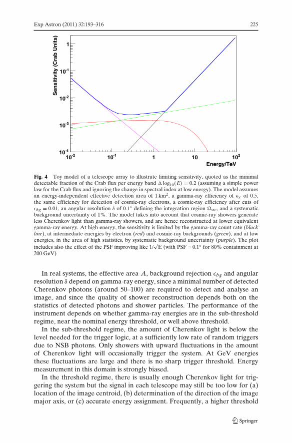
Exp Astron (2011) 32:193–316 225
Energy/TeV
-210 -110 1 10 210
Sen
siti
vity
(C
rab
Un
its)
-410
-310
-210
-110
1
Fig. 4 Toy model of a telescope array to illustrate limiting sensitivity, quoted as the minimaldetectable fraction of the Crab flux per energy band � log10(E) = 0.2 (assuming a simple powerlaw for the Crab flux and ignoring the change in spectral index at low energy). The model assumesan energy-independent effective detection area of 1 km2, a gamma-ray efficiency of εγ of 0.5,the same efficiency for detection of cosmic-ray electrons, a cosmic-ray efficiency after cuts ofεbg = 0.01, an angular resolution δ of 0.1◦ defining the integration region �src, and a systematicbackground uncertainty of 1%. The model takes into account that cosmic-ray showers generateless Cherenkov light than gamma-ray showers, and are hence reconstructed at lower equivalentgamma-ray energy. At high energy, the sensitivity is limited by the gamma-ray count rate (blackline), at intermediate energies by electron (red) and cosmic-ray backgrounds (green), and at lowenergies, in the area of high statistics, by systematic background uncertainty (purple). The plotincludes also the effect of the PSF improving like 1/
√E (with PSF = 0.1◦ for 80% containment at
200 GeV)
In real systems, the effective area A, background rejection εbg and angularresolution δ depend on gamma-ray energy, since a minimal number of detectedCherenkov photons (around 50–100) are required to detect and analyse animage, and since the quality of shower reconstruction depends both on thestatistics of detected photons and shower particles. The performance of theinstrument depends on whether gamma-ray energies are in the sub-thresholdregime, near the nominal energy threshold, or well above threshold.
In the sub-threshold regime, the amount of Cherenkov light is below thelevel needed for the trigger logic, at a sufficiently low rate of random triggersdue to NSB photons. Only showers with upward fluctuations in the amountof Cherenkov light will occasionally trigger the system. At GeV energiesthese fluctuations are large and there is no sharp trigger threshold. Energymeasurement in this domain is strongly biased.
In the threshold regime, there is usually enough Cherenkov light for trig-gering the system but the signal in each telescope may still be too low for (a)location of the image centroid, (b) determination of the direction of the imagemajor axis, or (c) accurate energy assignment. Frequently, a higher threshold

226 Exp Astron (2011) 32:193–316
than that given by the trigger is imposed in the data analysis. Most showerswith upward fluctuations will be reconstructed in a narrow energy range atthe trigger (or analysis) threshold. Sources with cut-offs below the analysisthreshold may be detectable but only at very high flux levels. Good imagingand spectroscopic performance of the instrument is only available at energies≥1.5× the trigger threshold.
High sensitivity over a wide energy range, therefore, requires an instrumentwhich is able to detect a sufficient number of Cherenkov photons for lowenergy showers, which covers a very large area for high-energy showers,and which provides high angular resolution and background rejection. Highangular resolution is also crucial to resolve fine structures in extended sourcessuch as supernova remnants. On the other hand, for the detection of extendedsources, the integration region �src is determined by the source size ratherthan the angular resolution and cosmic-ray rejection becomes a most criticalparameter in minimising statistical and systematic uncertainties.
A crucial question is therefore to which extent angular resolution andcosmic-ray rejection can be influenced by the design of the instrument, byparameters such as the number of Cherenkov photons detected or the sizeof the photo-sensor pixels. Simulation studies assuming an ideal instrument[59], one which detects all Cherenkov photons reaching the ground withperfect resolution for impact point and photon direction, show that achievableresolution and background rejection are ultimately limited by fluctuationsin the shower development. Angular resolution is in addition influenced bythe deflection of shower particles in the Earth’s magnetic field, making thereconstructed shower direction dependent on the energy sharing betweenelectron and positron in the first conversion of a gamma ray (Fig. 5). However,these resolution limits (Fig. 6) are well below the resolution achieved by cur-rent instruments. At 1 TeV, a resolution below one arc-minute is in principleachievable. Similar conclusions appear to hold for cosmic-ray backgroundrejection. There is a virtually irreducible background due to events in which, inthe first interaction of a cosmic ray, almost all the energy is transferred to oneor a few neutral pions and, therefore, to electromagnetic cascades (see, e.g.[60]). However, with their typical cosmic-ray rejection factors of >103 at TeVenergies, current instruments still seem 1–2 orders of magnitude away from this
Fig. 5 Two low-energygamma-ray showersdeveloping in the atmosphere.Both gamma rays wereincident vertically. Thedifference in shower directionresults from the energysharing between electronand positron in the firstconversion and thesubsequent deflection in theEarth’s magnetic field
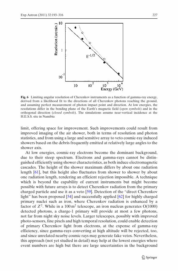
Exp Astron (2011) 32:193–316 227
Fig. 6 Limiting angular resolution of Cherenkov instruments as a function of gamma-ray energy,derived from a likelihood fit to the directions of all Cherenkov photons reaching the ground,and assuming perfect measurement of photon impact point and direction. At low energies, theresolutions differ in the bending plane of the Earth’s magnetic field (open symbols) and in theorthogonal direction (closed symbols). The simulations assume near-vertical incidence at theH.E.S.S. site in Namibia
limit, offering space for improvement. Such improvements could result fromimproved imaging of the air shower, both in terms of resolution and photonstatistics, and from using a large and sensitive array to veto cosmic-ray inducedshowers based on the debris frequently emitted at relatively large angles to theshower axis.
At low energies, cosmic-ray electrons become the dominant background,due to their steep spectrum. Electrons and gamma-rays cannot be distin-guished efficiently using shower characteristics, as both induce electromagneticcascades. The height of the shower maximum differs by about one radiationlength [61], but this height also fluctuates from shower to shower by aboutone radiation length, rendering an efficient rejection impossible. A techniquewhich is beyond the capability of current instruments but might becomepossible with future arrays is to detect Cherenkov radiation from the primarycharged particle and use it as a veto [59]. Detection of the “direct Cherenkovlight” has been proposed [54] and successfully applied [62] for highly chargedprimary nuclei such as iron, where Cherenkov radiation is enhanced by afactor of Z 2. While in a 100 m2 telescope, an iron nucleus generates O(1000)detected photons, a charge-1 primary will provide at most a few photons,not far from night sky noise levels. Larger telescopes, possibly with improvedphoto-sensors, fine pixels and high temporal resolution, could enable detectionof primary Cherenkov light from electrons, at the expense of gamma-rayefficiency, since gamma-rays converting at high altitude will be rejected, too,and since unrelated nearby cosmic rays may generate fake vetos. Nevertheless,this approach (not yet studied in detail) may help at the lowest energies whereevent numbers are high but there are large uncertainties in the background
228 Exp Astron (2011) 32:193–316
systematics. Sakahian et al. [63] note that at energies <20 GeV, deflectionof electrons in the Earth’s magnetic field is sufficiently large to disperseCherenkov photons over a larger area on the ground, reducing light densityand therefore the electron-induced trigger rate. The effect is further enhancedby a dispersion in photon arrival times.
In summary, it is clear that the performance of Cherenkov telescopearrays can be improved significantly, before fundamental limitations arereached.
6 The Cherenkov Telescope Array
The CTA consortium plans to operate from one site in the southern and onein the northern hemisphere, allowing full-sky coverage. The southern site willcover the central part of the galactic plane and see most of the galactic sourcesand will therefore be designed to have sensitivity over the full energy range.The northern site will be optimised for extragalactic astronomy, and will notrequire coverage of the highest energies.
Determining the arrangement and characteristics of the CTA telescopesin the two arrays is a complex optimisation problem, balancing cost againstperformance in different bands of the spectrum. This section will address thegeneral criteria and considerations for this optimisation, while the technicalimplementation is covered in the following sections.
6.1 Array layout
Given the wide energy range to be covered, a uniform array of identicaltelescopes, with fixed spacing, is not the most efficient solution for the CTA.For the purpose of discussion, separation into three energy ranges, withoutsharp boundaries, is appropriate:
The low-energy range ≤100 GeV To detect showers down to a few tens ofGeV, the Cherenkov light needs to be sampled and detected efficiently,with the fraction of area covered by light collectors being of the orderof 10% (assuming conventional PMT light sensors). Since event ratesare high and systematic background uncertainties are likely to limit theachievable sensitivity, the area of this part of the array can be relativelysmall, being of order of a few 104 m2. Efficient photon detection can beachieved either with few large telescopes or many telescopes of modestsize. For very large telescopes, the cost of the dish structures dominates, forsmall telescopes the photon detectors and electronics account for the bulkof the cost. A (shallow) cost optimum in terms of cost per telescope areais usually reached for medium-sized telescopes in the 10–15 m diameterrange. However, if small to medium-sized telescopes are used in thisenergy range, the challenge is to trigger the array, since no individualtelescope detects enough Cherenkov photons to provide a reliable trigger
Exp Astron (2011) 32:193–316 229
signal. Trigger systems which combine and superimpose images at the pixellevel in real time, with a time resolution of a few ns, can address thisissue [64] but represent a significant challenge, given that a single 1,000-pixel telescope sampled at (only) 200 MHz and 8 bits per pixel generates adata stream of more than one Tb/s. CTA designs conservatively assume asmall number of very large telescopes, typically with about a 20–30 m dishdiameter, to cover the low energy range.
The core energy range from about 100 GeV to about 10 TeV shower detectionand reconstruction in this energy range are well understood from currentinstruments, and an appropriate solution seems a grid of telescopes ofthe 10–15 m class, with a spacing of about 100 m. Improved sensitivity isobtained both by the increased area covered, and by the higher qualityof shower reconstruction, since showers are typically imaged by a largernumber of telescopes than is the case for current few-telescope arrays.For the first time, array sizes will be larger than the Cherenkov lightpool, ensuring that images will be uniformly sampled across the lightpool, and that a number of images are recorded close to the optimumdistance from the shower axis (about 70–150 m), where the light intensityis large and intensity fluctuations are small, and where the shower axis isviewed under a sufficiently large angle for efficient reconstruction of itsdirection. At H.E.S.S. for example, events which are seen and triggered byall four telescopes provide significantly improved resolution and stronglyreduced backgrounds, but represent only a relatively small fraction ofevents. Unless energies are well above trigger threshold, only events withshower core locations within the telescope square can trigger all telescopes.A further advantage is that an extended telescope grid operated with atwo-telescope trigger condition will have a lower threshold than a smallarray, since there are always telescopes sufficiently close to the showercore.
The high-energy range above 10 TeV Here, the key limitation is the numberof detected gamma-ray showers and the array needs to cover multi-km2
areas. At high energies the light yield is large, so showers can be detectedwell beyond the 150-m radius of a typical Cherenkov light pool. Twoimplementation options can be considered: either a large number of smalltelescopes with mirror areas of a few m2 and spacing matched to the size ofthe light pool of 100–200 m, or a smaller number of larger telescopes withsome 10 m2 area which can see showers up to distance of ≥500 m, and canhence be deployed with a spacing of several 100 m, or in widely separatedsubclusters of a few telescopes. While it is not immediately obvious whichoptions offers best cost/performance ratio at high energies, the subclusterconcept with larger telescopes has the advantage of providing additionalhigh-quality shower detection towards lower energies, for impact pointsnear the subcluster.
Figure 7 shows possible geometries of arrays with separate regions opti-mized for low, intermediate and high energies.
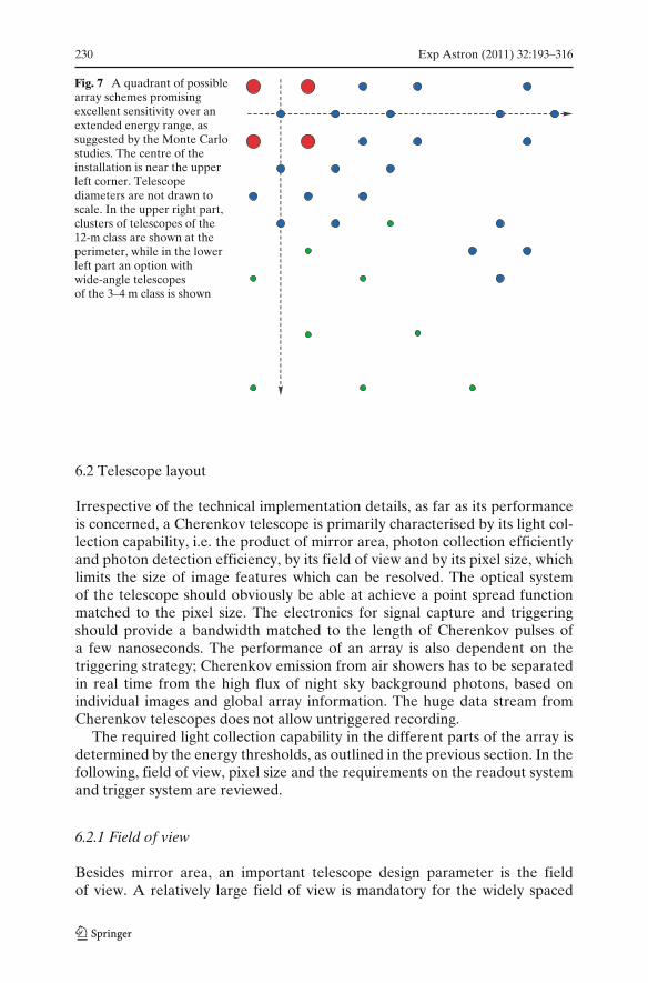
230 Exp Astron (2011) 32:193–316
Fig. 7 A quadrant of possiblearray schemes promisingexcellent sensitivity over anextended energy range, assuggested by the Monte Carlostudies. The centre of theinstallation is near the upperleft corner. Telescopediameters are not drawn toscale. In the upper right part,clusters of telescopes of the12-m class are shown at theperimeter, while in the lowerleft part an option withwide-angle telescopesof the 3–4 m class is shown
6.2 Telescope layout
Irrespective of the technical implementation details, as far as its performanceis concerned, a Cherenkov telescope is primarily characterised by its light col-lection capability, i.e. the product of mirror area, photon collection efficientlyand photon detection efficiency, by its field of view and by its pixel size, whichlimits the size of image features which can be resolved. The optical systemof the telescope should obviously be able at achieve a point spread functionmatched to the pixel size. The electronics for signal capture and triggeringshould provide a bandwidth matched to the length of Cherenkov pulses ofa few nanoseconds. The performance of an array is also dependent on thetriggering strategy; Cherenkov emission from air showers has to be separatedin real time from the high flux of night sky background photons, based onindividual images and global array information. The huge data stream fromCherenkov telescopes does not allow untriggered recording.
The required light collection capability in the different parts of the array isdetermined by the energy thresholds, as outlined in the previous section. In thefollowing, field of view, pixel size and the requirements on the readout systemand trigger system are reviewed.
6.2.1 Field of view
Besides mirror area, an important telescope design parameter is the fieldof view. A relatively large field of view is mandatory for the widely spaced
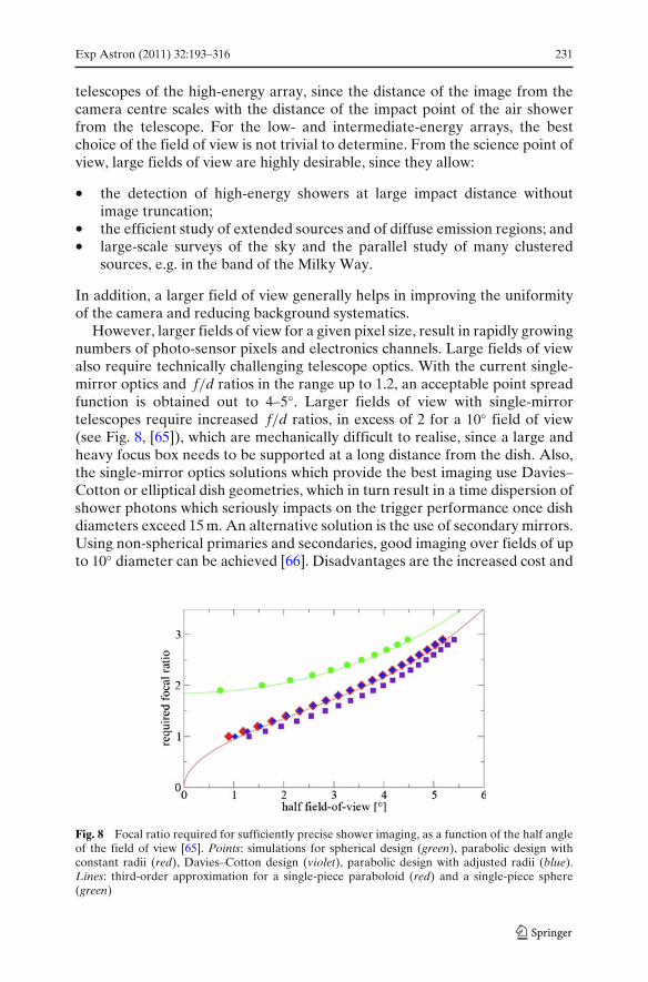
Exp Astron (2011) 32:193–316 231
telescopes of the high-energy array, since the distance of the image from thecamera centre scales with the distance of the impact point of the air showerfrom the telescope. For the low- and intermediate-energy arrays, the bestchoice of the field of view is not trivial to determine. From the science point ofview, large fields of view are highly desirable, since they allow:
• the detection of high-energy showers at large impact distance withoutimage truncation;
• the efficient study of extended sources and of diffuse emission regions; and• large-scale surveys of the sky and the parallel study of many clustered
sources, e.g. in the band of the Milky Way.
In addition, a larger field of view generally helps in improving the uniformityof the camera and reducing background systematics.
However, larger fields of view for a given pixel size, result in rapidly growingnumbers of photo-sensor pixels and electronics channels. Large fields of viewalso require technically challenging telescope optics. With the current single-mirror optics and f/d ratios in the range up to 1.2, an acceptable point spreadfunction is obtained out to 4–5◦. Larger fields of view with single-mirrortelescopes require increased f/d ratios, in excess of 2 for a 10◦ field of view(see Fig. 8, [65]), which are mechanically difficult to realise, since a large andheavy focus box needs to be supported at a long distance from the dish. Also,the single-mirror optics solutions which provide the best imaging use Davies–Cotton or elliptical dish geometries, which in turn result in a time dispersion ofshower photons which seriously impacts on the trigger performance once dishdiameters exceed 15 m. An alternative solution is the use of secondary mirrors.Using non-spherical primaries and secondaries, good imaging over fields of upto 10◦ diameter can be achieved [66]. Disadvantages are the increased cost and
Fig. 8 Focal ratio required for sufficiently precise shower imaging, as a function of the half angleof the field of view [65]. Points: simulations for spherical design (green), parabolic design withconstant radii (red), Davies–Cotton design (violet), parabolic design with adjusted radii (blue).Lines: third-order approximation for a single-piece paraboloid (red) and a single-piece sphere(green)
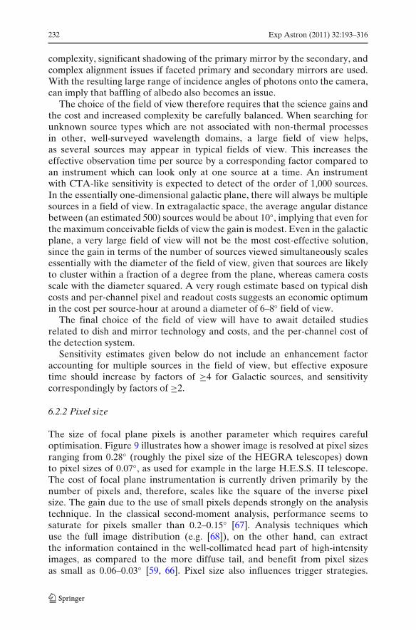
232 Exp Astron (2011) 32:193–316
complexity, significant shadowing of the primary mirror by the secondary, andcomplex alignment issues if faceted primary and secondary mirrors are used.With the resulting large range of incidence angles of photons onto the camera,can imply that baffling of albedo also becomes an issue.
The choice of the field of view therefore requires that the science gains andthe cost and increased complexity be carefully balanced. When searching forunknown source types which are not associated with non-thermal processesin other, well-surveyed wavelength domains, a large field of view helps,as several sources may appear in typical fields of view. This increases theeffective observation time per source by a corresponding factor compared toan instrument which can look only at one source at a time. An instrumentwith CTA-like sensitivity is expected to detect of the order of 1,000 sources.In the essentially one-dimensional galactic plane, there will always be multiplesources in a field of view. In extragalactic space, the average angular distancebetween (an estimated 500) sources would be about 10◦, implying that even forthe maximum conceivable fields of view the gain is modest. Even in the galacticplane, a very large field of view will not be the most cost-effective solution,since the gain in terms of the number of sources viewed simultaneously scalesessentially with the diameter of the field of view, given that sources are likelyto cluster within a fraction of a degree from the plane, whereas camera costsscale with the diameter squared. A very rough estimate based on typical dishcosts and per-channel pixel and readout costs suggests an economic optimumin the cost per source-hour at around a diameter of 6–8◦ field of view.
The final choice of the field of view will have to await detailed studiesrelated to dish and mirror technology and costs, and the per-channel cost ofthe detection system.
Sensitivity estimates given below do not include an enhancement factoraccounting for multiple sources in the field of view, but effective exposuretime should increase by factors of ≥4 for Galactic sources, and sensitivitycorrespondingly by factors of ≥2.
6.2.2 Pixel size
The size of focal plane pixels is another parameter which requires carefuloptimisation. Figure 9 illustrates how a shower image is resolved at pixel sizesranging from 0.28◦ (roughly the pixel size of the HEGRA telescopes) downto pixel sizes of 0.07◦, as used for example in the large H.E.S.S. II telescope.The cost of focal plane instrumentation is currently driven primarily by thenumber of pixels and, therefore, scales like the square of the inverse pixelsize. The gain due to the use of small pixels depends strongly on the analysistechnique. In the classical second-moment analysis, performance seems tosaturate for pixels smaller than 0.2–0.15◦ [67]. Analysis techniques whichuse the full image distribution (e.g. [68]), on the other hand, can extractthe information contained in the well-collimated head part of high-intensityimages, as compared to the more diffuse tail, and benefit from pixel sizesas small as 0.06–0.03◦ [59, 66]. Pixel size also influences trigger strategies.
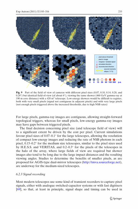
Exp Astron (2011) 32:193–316 233
pixel above threshold
pixel in image
marginal / isolated signal
simulated direction
reconstructed direction
second moments
ellipse (*1/*2)
0 6 15 30 60 150 300 p.e.
Fig. 9 Part of the field of view of cameras with different pixel sizes (0.07, 0.10, 0.14, 0.20, and0.28◦) but identical field-of-view (of about 6◦), viewing the same shower (460 GeV gamma-ray at190 m core distance) with a 420 m2 telescope. Low-energy showers would be difficult to register,both with very small pixels (signal not contiguous in adjacent pixels) and with very large pixels(not enough pixels triggered above the increased thresholds, due to high NSB rates)
For large pixels, gamma-ray images are contiguous, allowing straight-forwardtopological triggers, whereas for small pixels, low-energy gamma-ray imagesmay have gaps between triggered pixels.
The final decision concerning pixel size (and telescope field of view) willto a significant extent be driven by the cost per pixel. Current simulationsfavour pixel sizes of 0.07–0.1◦ for the large telescopes, allowing the resolutionof compact low-energy images and reducing the rate of NSB photons in eachpixel, 0.15–0.2◦ for the medium size telescopes, similar to the pixel sizes usedby H.E.S.S. and VERITAS, and 0.2–0.3◦ for the pixels of the telescopes inthe halo of the array, where large fields of view are required but showerimages also tend to be long due to the large impact distances and the resultingviewing angles. Studies to determine the benefits of smaller pixels, as areproposed for AGIS-type dual-mirror telescopes (http://tmva.sourceforge.net),are underway for the medium-sized telescopes.
6.2.3 Signal recording
Most modern telescopes use some kind of transient recorders to capture pixelsignals, either with analogue switched-capacitor systems or with fast digitisers[69], so that, at least in principle, signal shape and timing can be used in

234 Exp Astron (2011) 32:193–316
the image analysis. Signal shape and timing can be employed in two ways:(a) to reject backgrounds such as hadronic showers and local muons; and(b) to reduce the signal integration windows and hence the amount of NSBnoise in the shower image. For example, muon rejection based on signalwaveform is discussed in [70]. Quantifying how much background rejection canbe improved using these techniques is non-trivial. The effect of signal-shapeimage selection is correlated with other cuts imposed in the analysis. For singletelescopes, signal shape and timing can provide significant improvements.For telescope systems, the cuts on image shapes in multiple telescopes arealready very powerful and background events passing these cuts will haveimages and signal shapes that look very much like those of gamma-rays,so that less improvement is expected, if any. The second area where signalwaveform recording can improve performance concerns the signal amplitudes.In particular for larger shower impact parameters, photon arrival times arenot isochronous across the image (Fig. 10), and photons in the “tail” end ofthe image arrive with significant delays compared to those from its “head”.Use of variable and matched integration windows across the image allows theextraction of shower signals with minimal contamination from NSB noise. Useof signal shape and timing information is already used in the current MAGIC[71] and VERITAS systems, and these results will help to guide final designchoices for CTA.
0.0 ns 2.0 ns
5.0 ns 10.0 ns 16.0 ns
sum
Fig. 10 Integrated signal (upper left) and 1 ns samples of the development of a 10 TeV gammashower at 250 m core distance as seen in a telescope with optics and pixels similar to a H.E.S.S.-1telescope but with a FoV of 10◦ diameter. Pixels near the “head” of the shower have a pulse widthdominated by the single photoelectron pulse width, while those in the “tail” of the shower seelonger pulses. The shower image moves across almost half the FoV in about 25 ns
Exp Astron (2011) 32:193–316 235
The performance numbers quoted for the simulations described below areconservative in that they are based on fixed (and relatively large) signalintegration windows. Improvements can be expected once the use of imageshape information is fully understood.
6.2.4 Trigger
The trigger scheme and readout electronics are closely related and funda-mentally influence the design and performance of the telescope array. Formost applications, multi-telescope trigger coincidence is required to rejectbackgrounds at the trigger level and to reduce the load on the data acquisitionsystem. The main issue here is how much information is exchanged betweentelescopes, and how image information is stored while the trigger decision ismade.
One extreme scenario is to let each telescope trigger independently and onlyexchange a trigger flag with neighbouring telescopes, allowing identificationof coincident triggers (e.g. [72]). The energy threshold of the system is thendetermined by the minimum threshold at which a telescope can trigger. Theother extreme is to combine signals from different telescopes at the pixel level,either in analogue or digital form, and to extract common image features. Inthis case, the system energy threshold could be well below the thresholds ofindividual telescopes, which is important when the array is made up of manysmall or medium-sized telescopes. However, the technical complexity of sucha solution is significant. There is a wide range of intermediate solutions, wheretrigger pre-processors extract image features, such as the image centroid, on atelescope basis and the system trigger decision includes this information.
In cases where individual telescopes generate a local trigger, pixel signalsneed to be stored while a global trigger decision is made. The time for whichsignals can be stored without introducing deadtime, is typically ms in the caseof digital storage and μs if analogue storage is used, which strongly influencesthe design of higher level triggers.
Trigger topology is another important issue. Triggers can either be derivedlocally within the array by some trigger logic connecting neighbouring tele-scopes, or all trigger information can be routed to a central station wherea global decision is made, which is then propagated back to the telescopes.The first approach requires shorter signal storage at the telescopes and ismore easily scaled up to large arrays, the second provides maximum flexibility.Whether local or global, trigger schemes will employ a multi-level hierarchy,with a first trigger level acting on pixels and pixel groups, and higher levelsusing information on image topology and/or the topology of triggered tele-scopes in the array. As in modern high-energy physics experiments, triggerdecisions will, to the extent possible, be performed using programmable ratherthan “hardwired” processors. If the signal is recorded using fast digitisers,even the first-level discrimination of pixel signals could be implementeddigitally in the gate array controlling the digitiser, instead of applying analoguethresholds.

236 Exp Astron (2011) 32:193–316
Whatever implementation is chosen, it is important that the trigger system isvery flexible and software-configurable, since operation modes vary from deepobservations, where all telescopes follow the same source, to monitoring orsurvey applications, where groups of a few telescopes or even single telescopespoint in different directions.
The simulations discussed below assume a very conservative approach. Eachtelescope makes an independent trigger decision with thresholds defined suchthat the telescope trigger rate is in the manageable range of a few to some tensof kHz. This is followed by a global decision based on the number of triggeredtelescopes.
6.3 CTA performance summary
Section 8 gives a detailed description of the layout and performance studiesconducted so far for CTA. Many candidate layouts have been considered.Here we provide a brief description of the nature and performance of onepromising configuration (E), which is illustrated in Fig. 18. This configurationutilises three telescope types: four 24 m telescopes with 5◦ field-of-view and0.09◦ pixels, 23 telescopes of 12 m diameter with 8◦ field-of-view and 0.18◦pixels, and 32 telescopes of 7 m diameter with a 10◦ field-of-view and 0.25◦pixels. The telescopes are distributed over ∼3 km2 on the ground and theeffective collection area of the array is considerably larger than this at energiesbeyond 10 TeV. The sensitivity of array E from detailed calculations andusing standard data analysis techniques is shown in Fig. 23. More sophisticatedanalyses result in sensitivities that are ∼20% better across the whole energyrange. As Fig. 23 shows, such an array performs an order of magnitude betterthan an instrument like H.E.S.S. over most of required energy range. Figure 25shows the angular resolution of this array, which approaches one arcminute athigh energies. The energy resolution of layout E is better than 10% above afew hundred GeV.
Array layout E has a nominal construction cost of 80 Me and meets themain design goals of CTA. Given that the configuration itself, and the analysismethods used, have not yet been optimised, it is likely that a significantly bettersensitivity can be achieved with an array of this nominal cost which followsthe same basic concept. Therefore, despite the uncertainties in the cost modelemployed (see Section 7.5), we are confident that the design goals of CTA canbe realised at close to the envisaged cost.
7 Realizing CTA
This section provides a brief overview of the position of CTA in the Europeanand global context, the organisation of CTA during the various stages, of itsoperation as an open observatory, of the potential sites envisaged for CTA,and of the schedule for and cost of CTA design, construction and operation.

Exp Astron (2011) 32:193–316 237
7.1 CTA and the European strategy in astrophysics and astroparticle physics
CTA, as a major future facility for astroparticle physics, is firmly embeddedin the European processes guiding science in the fields of astronomy andastroparticle physics.
The European Strategy Forum on Research Infrastructures (ESFRI) ESFRI isa strategic organisation whose objective is to promote the scientific integra-tion of Europe, to strengthen the European Research Area and to increaseits international impact. A first Roadmap for pan-European researchinfrastructures was released in 2006, listing CTA as an “emerging project”.In the December 2008 update of this Roadmap, CTA was included asone of eight Physical Sciences and Engineering projects, together withfacilities such as E-ELT, KM3Net and SKA. As such, CTA is eligible forFP7 Preparatory Phase funding. The CTA application for this funding wassuccessful, providing up to 5.2 Me for the preparation of the constructionof the observatory in 3 years time. The contracts with the EC are in theprocess of being finalised and signed.
The Astroparticle Physics European Coordination (ApPEC) group ApPECwas created to enhance coordination in astroparticle physics across Eu-rope. It has stimulated cooperation and convergence between competinggroups in Europe, and has initiated the production of a European roadmapin astroparticle physics, on which CTA is one of the key projects.
ASPERA ASPERA is a network of national government agencies responsiblefor coordinating and funding national research efforts in AstroparticlePhysics. One of the tasks of ASPERA is to create a scientific roadmap forAstroparticle Physics (http://www.aspera-eu.org/images/stories/roadmap/aspera_roadmap.pdf) and link it with the more general European scientificinfrastructure roadmap. A Phase I roadmap has been published, present-ing the overarching science questions and the new instruments plannedto address these questions. Phase II saw the release of the resulting“European Strategy for Astroparticle Physics” in September 2008, priori-tising the projects under consideration. In this roadmap, CTA emerges asa near-term high-priority project. The roadmap states:The priority project for VHE gamma-ray astrophysics is the CherenkovTelescope Array, CTA. We recommend design and prototyping of CTA, theselection of sites, and proceeding rapidly towards start of deployment in 2012.CTA was one of the two projects targeted by the 2009 ASPERA CommonCall for cross-national funding and received in total 2.7 Me from nationalfunding agencies.
The ASTRONET Eranet ASTRONET was created by a group of Europeanfunding agencies to establish comprehensive long-term planning for thedevelopment of European astronomy. The objective of this effort is toconsolidate and reinforce the world-leading position that European astron-omy attained at the beginning of this century. Late in 2008, ASTRONETreleased “The ASTRONET Infrastructure Roadmap: A Strategic Plan for
238 Exp Astron (2011) 32:193–316
European Astronomy”. CTA is one of the three medium-scale facilitiesrecommended on this roadmap, together with the neutrino telescopeKM3Net and the solar telescope EST.
7.2 CTA in the world-wide context
Ground-based gamma-ray astronomy has attracted considerable attentionworld-wide, and while CTA is the key project in Europe, other projects havebeen considered elsewhere. These include primarily:
The Advanced Gamma-ray Imaging System (AGIS) In both science an instru-mentation, AGIS (http://www.agis-observatory.org/) followed a very simi-lar plan to that of CTA. The AGIS project was presented in a White Paperprepared for the Division of Astrophysics of the American Physical Society[8]. AGIS proposed a square-kilometre array of mid-sized telescopes,similar to the core array of mid-sized telescopes in CTA but without the ad-ditional large telescopes to cover the very lowest energies, and an extendedarray of small telescopes to provide large detection area at the very highestenergies. The baseline configuration of AGIS consisted of 36 two-mirrorSchwarzschild-Couder telescopes with an 11.5 m diameter primary mirror.These have a large field of view and a very good angular resolution. Closecontacts were established between AGIS and CTA, during the designstudy phase; information was openly exchanged and common develop-ments undertaken. After a US review panel recommended that AGIS joinforces with CTA, the US members of the AGIS Collaboration have joinedCTA in spring 2010. Within the overall context of CTA, developmentof Schwarzschild-Couder telescopes will be continued to investigate theirpotential for further improving CTA performance. Significant intellectual,technological and financial contributions to CTA from the US groups areanticipated. Strong US participation in CTA was endorsed by PASAG4
and the Decadal Survey in Astronomy and Astrophysics (Astro-2010).The High-Altitude Water-Cherenkov Experiment (HAWC) HAWC
(http://hawc.umd.edu/) builds on the technique developed by theMILAGRO group, which detects shower particles on the ground usingwater Cherenkov detectors, and reconstructs the shower direction usingtiming information. It is proposed to construct the new detector on asite at 4,100 m a.s.l. in the Sierra Negra, Mexico. HAWC will provide atenfold increase in sensitivity over MILAGRO and detection capabilitydown to the lower energy of 100 GeV, largely due to its increased altitude.While it will have lower sensitivity, poorer angular resolution and ahigher energy threshold compared to CTA, HAWC has the advantageof a large field of view (≈ 2π sr) and nearly 100% duty cycle. HAWCtherefore complements imaging Cherenkov instruments. In fact, it would
4Particle Astrophysics Scientific Assessment Group of the High Energy Physics Advisory Panel

Exp Astron (2011) 32:193–316 239
be desirable to construct and operate a similar instrument in the southernhemisphere, co-located with CTA.
The Large High Altitude Air Shower Observatory (LHAASO) LHAASOis an extensive (km2) cosmic ray experiment. The proposal is to locatethis near the site of the ARGO and AS-Gamma experiments in Tibet,at 4,300 m a.s.l. The array includes large-scale water Cherenkov detectors(90,000 m2), ground scintillation counter arrays for detecting both muonsand electromagnetic particles, fluorescence/Cherenkov telescope arraysand a shower core detector array. The science goals encompass a surveyof gamma-ray sources in the energy range ≥100 GeV, measurement ofgamma-ray energy spectra of sources above 30 TeV to identify cosmicray sources, and the measurement of cosmic ray spectra and compositionat energies above 30 TeV. If realised, LHASSO will complement thenorthern CTA array, as it concentrates primarily on the detection of low-energy gamma-rays in the energy range from a few times 10 GeV to some100 GeV.
In summary, the other large-scale instruments for ground-based gamma-rayastronomy that are being discussed outside Europe (e.g. HAWC, LHAASO),are complementary to CTA in their capabilities.
7.3 Operation of CTA as an open observatory
CTA is to address a wide range of astroparticle physics and astrophysicsquestions. The majority of studies will be based on observations of specificastronomical sources. The scientific programme will hence be steered byproposals to conduct measurements of specific objects. CTA will be operatedas an open observatory. Beyond a base programme, which will include forexample a survey of the Galaxy and deep observations of “legacy sources”,observations will be conducted according to observing proposals selected forscientific excellence by peer-review among suggestions received from thecommunity. Following the general procedures developed for and by othermajor astrophysical facilities, a substantial number of outstanding proposalsfrom scientists working in institutions outside the CTA-supporting countrieswill be executed. All data obtained by the CTA will be made available in anarchive that is accessible to scientists outside the proposing team.
Following the experience of currently operating Cherenkov telescope obser-vatories, the actual observations will normally be conducted over an extendedperiod in time, with several different projects being scheduled each night.The operation of the array will be fairly complex. CTA observations willnot, therefore, be conducted by the scientists whose individual proposals wereselected, but by a dedicated team of operators.
CTA observatory operation involves proposal handling and evaluation,managing observation and data-flow, and maintenance. The actual work maybe conducted in a central location or in decentralised units (e.g. a data centreand an operations centre) with a coordinating office.
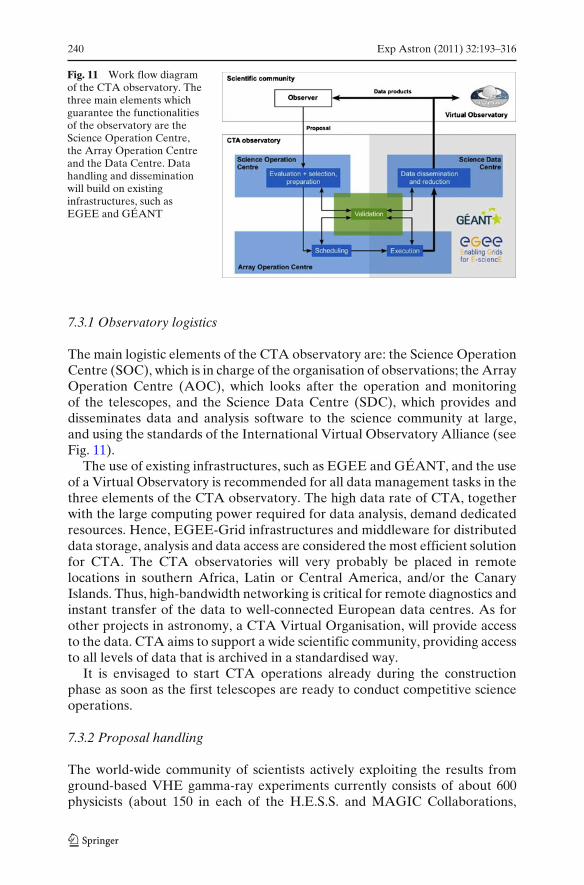
240 Exp Astron (2011) 32:193–316
Fig. 11 Work flow diagramof the CTA observatory. Thethree main elements whichguarantee the functionalitiesof the observatory are theScience Operation Centre,the Array Operation Centreand the Data Centre. Datahandling and disseminationwill build on existinginfrastructures, such asEGEE and GÉANT
7.3.1 Observatory logistics
The main logistic elements of the CTA observatory are: the Science OperationCentre (SOC), which is in charge of the organisation of observations; the ArrayOperation Centre (AOC), which looks after the operation and monitoringof the telescopes, and the Science Data Centre (SDC), which provides anddisseminates data and analysis software to the science community at large,and using the standards of the International Virtual Observatory Alliance (seeFig. 11).
The use of existing infrastructures, such as EGEE and GÉANT, and the useof a Virtual Observatory is recommended for all data management tasks in thethree elements of the CTA observatory. The high data rate of CTA, togetherwith the large computing power required for data analysis, demand dedicatedresources. Hence, EGEE-Grid infrastructures and middleware for distributeddata storage, analysis and data access are considered the most efficient solutionfor CTA. The CTA observatories will very probably be placed in remotelocations in southern Africa, Latin or Central America, and/or the CanaryIslands. Thus, high-bandwidth networking is critical for remote diagnostics andinstant transfer of the data to well-connected European data centres. As forother projects in astronomy, a CTA Virtual Organisation, will provide accessto the data. CTA aims to support a wide scientific community, providing accessto all levels of data that is archived in a standardised way.
It is envisaged to start CTA operations already during the constructionphase as soon as the first telescopes are ready to conduct competitive scienceoperations.
7.3.2 Proposal handling
The world-wide community of scientists actively exploiting the results fromground-based VHE gamma-ray experiments currently consists of about 600physicists (about 150 in each of the H.E.S.S. and MAGIC Collaborations,

Exp Astron (2011) 32:193–316 241
about 100 in VERITAS, 50 in Cangaroo and 50 in Indian gamma ray activities,plus about 100 scientists either associated, or regularly collaborating, withthese experiments). Planning and designing CTA involves about another100 scientists not currently participating in either of the currently runningexperiments. Proposals for observations with CTA are hence expected toserve a community of at least 700 scientists, larger than that of any nationalastronomical facility in Europe, and comparable to the size of the communityusing the ESO observatory in the 1980s. CTA must therefore efficiently dealwith a large number of proposals for a facility which, based on experiencewith current experiments, is expected to be oversubscribed by a large factor.CTA plans to follow the practice of other major, successful observatories (e.g.ESO), and announce calls for proposals at regular intervals. These proposalswill be peer-reviewed by a group of international experts which will change ona regular basis. Different classes of proposals (targeted, surveys, time-critical,target of opportunity, and regular programmes) are foreseen, as is commonfor current experiments and other ground-based observatories. Depending onthe science under investigation, subarray operation may be required. Eachsite may therefore be conducting several different observation programmesconcurrently.
7.3.3 Observatory operations
The observing programme of the CTA will be driven by the best proposalsfrom the scientific community, which will be selected in a peer-review process.Successful applicants will provide all the information required for the optimumcompletion of their measurements. An observing programme will be compiledby the operations centre, taking the requirements of individual projects intoaccount. The programme will be conducted in robotic fashion with a minimumamount of professional staff on site. Proposers are not expected to partici-pate in measurements. Quicklook analysis will enable triggers and on-the-flymodification of projects, if required. Data and calibration files will be providedto the user. Frequent modifications to the scheduled observing programmecan be expected for several reasons. Openness of triggers is essential giventhe transitory and variable nature of many of the phenomena to be studiedby CTA. CTA must adapt its schedule to changing atmospheric conditions toensure the science programme is optimised. The flexibility to pursue severalpotentially very different programmes at the same time may increase theproductivity of the CTA observatory. Routine calibrations and monitoring ofthe array and of environmental data must be scheduled as needed to ensurethe required data quality.
Observatory operations covers day-to-day use of the arrays, includingmeasurements and continuous hardware and software maintenance, proposalhandling and evaluation, automated analysis and user support, as well as thelong-term programme for upgrades and improvements to ensure continuedcompetitiveness over the lifetime of the observatory.
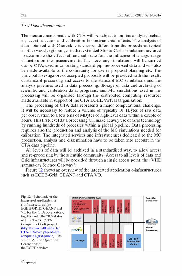
242 Exp Astron (2011) 32:193–316
7.3.4 Data dissemination
The measurements made with CTA will be subject to on-line analysis, includ-ing event-selection and calibration for instrumental effects. The analysis ofdata obtained with Cherenkov telescopes differs from the procedures typicalin other wavelength ranges in that extended Monte-Carlo simulations are usedto determine the effects of, and calibrate for, the influence of a large rangeof factors on the measurements. The necessary simulations will be carriedout by CTA, used in calibrating standard pipline-processed data and will alsobe made available to the community for use in proposal planning etc. Theprincipal investigators of accepted proposals will be provided with the resultsof standard processing and access to the standard MC simulations and theanalysis pipelines used in data processing. Storage of data and archiving ofscientific and calibration data, programs, and MC simulations used in theprocessing will be organised through the distributed computing resourcesmade available in support of the CTA EGEE Virtual Organisation.
The processing of CTA data represents a major computational challenge.It will be necessary to reduce a volume of typically 10 TBytes of raw dataper observation to a few tens of MBytes of high-level data within a couple ofhours. This first-level data processing will make heavily use of Grid technologyby running hundreds of processes within a global pipeline. Data processingrequires also the production and analysis of the MC simulations needed forcalibration. The integrated services and infrastructures dedicated to the MCproduction, analysis and dissemination have to be taken into account in theCTA data pipeline.
All levels of data will be archived in a standardised way, to allow accessand re-processing by the scientific community. Access to all levels of data andGrid infrastructures will be provided through a single access point, the “VHEgamma-ray Science Gateway”.
Figure 12 shows an overview of the integrated application e-infrastructuressuch as EGEE-Grid, GÉANT and CTA VO.
Fig. 12 Schematic of theintegrated application ofe-infrastructures likeEGEE-GRID, GÉANT andVO for the CTA observatory,together with the 2009 statusof the CTACG (CTAComputing Grid) project(http://lappwiki01.in2p3.fr/CTA-FR/doku.php?id=cta-computing-grid-public). TheVO-CTA Grid OperationCentre housesthe EGEE services
Exp Astron (2011) 32:193–316 243
It is foreseen that the high level analysis of CTA data can be conducted byindividual scientists using the analysis software made available by CTA. Thissoftware will follow the standards used by other high-energy observatories andwill be provided free of charge to the scientific community.
7.4 CTA organisation
The organisation of the CTA consortium will evolve over the various stages ofthe project. These include:
The design study phase. Definition of the layout of the arrays, specification ofthe telescope types, design of the telescopes and small-scale prototyping.
The prototyping and preparatory phase. Prototyping and deployment of full-scale telescopes, preparation of the construction and installation includingsolving technical, organisational and legal issues, site preparation.
Construction phase. Construction, deployment and commissioning of the tele-scopes.
Operation Phase. Operation as an open observatory, with calls for proposalsand scheduling, operation and maintenance of the facility, processing ofthe data and provision of analysis tools.
For the design study phase, the organisation of the consortium was defined ina Memorandum of Understanding modelled on those proven by large experi-ments in particle and astroparticle physics. The governing body is the Consor-tium Board and operational decisions are taken and work is coordinated by theSpokespersons and the Executive Board. Work Package Convenors organiseand drive the work on essential parts of the project. The work packages andthe area they cover are:
PHYS The astrophysics and astroparticle physics that will be studied usingCTA.
MC Development of simulations for optimisation of the array layoutand analysis algorithms, and for performance studies.
SITE Evaluation of possible sites for CTA and infrastructurerequirements.
MIR Design of telescope optics and mirror construction.TEL Design of telescope structure and associated drive and control
systems.FPI Development of focal plane instrumentation.ELEC Design and development of the readout electronics and trigger.ATAC Development of atmospheric monitoring and calibration techniques
and associated instrumentation.OBS Development of observatory operation and access strategies.DATA Studies of data handling, processing, management and data access.QA Quality assurance and risk assessment strategies.
The CTA design study phase was organised in terms of scientific/technicaltopics, rather than in terms of telescope types, to ensure that, as far as

244 Exp Astron (2011) 32:193–316
possible, common technical solutions are employed across the array, maximis-ing economies of scale and simplifying array operation.
For the preparatory phase, the organisation will be adapted to the needs ofthe project. The Project Office will be extended, and work packages for eachtelescope type will be established to steer prototyping and preparations forconstruction. External advisors will assist in guiding and reviewing the project.
A significant task for the preparatory phase will be the definition of thelegal framework and governance structure of the CTA Collaboration andobservatory. Different models exist, each of which has its own advantagesand disadvantages. CTA could for example be realised within an existinginternational organisation such as CERN or ESO. CTA could also be operatedby a large national laboratory which has sufficient administrative and technicalinfrastructure. Suitable national laboratories exist e.g. in Germany, France, orthe UK, for example. On a smaller scale, H.E.S.S. and MAGIC are operatedin this mode. CTA could be established as an independent legal entity underthe national law of some country, following the example of IRAM. Thedefinition of the legal structure of CTA will be determined in close interactionwith ASPERA (a group of European Research Area funding agencies whichcoordinates astroparticle physics in Europe). One of their main tasks is the“Implementation of new European-wide procedures for large infrastructures”.
Regardless of the legal implementation, CTA management will be assistedby an international scientific and technical Advisory Board, and a ResourceBoard, composed of representatives of the national funding organisationssupporting CTA.
Close contacts between CTA and the funding agencies (via the ResourceBoard) during all stages of the project are vital to secure sufficient and timelyfunding for the construction of the facility.
7.5 Time schedule and costs
CTA builds largely on proven technologies and Cherenkov telescopes of sizessimilar to those needed for CTA have already been built or are in the advancedstages of construction. Remaining challenges are: (a) optimisation of thecost of telescope components; (b) improvement of the reliability of telescopecomponents, requiring extensive prototyping; (c) establishment of the formalframework for building and operating the instrument, and the selection andprovision of sites; and (d) the funding of the infrastructure.
These challenges will be addressed during the Preparatory Phase (2010–2013) which will be supported by an FP7 grant of up to 5.2 Me from theEuropean Community and by grants from various national funding agencies.
After a successful Preparatory Phase, and provided the funding has beensecured, construction and deployment will then take from 2013 until 2018.
A detailed evaluation of the required construction and running costs ispart of the Preparatory Phase studies. Current design efforts are conductedwithin an envelope of investment costs for the CTA construction and siteinfrastructure of 100 Me for the southern site, featuring full energy coverage,
Exp Astron (2011) 32:193–316 245
and 50 Me for the more specialised northern site (all in 2005 e). CTA aimsto keep running costs below 10% of the total investment, in line with typicalrunning costs for other astrophysical facilities.
Estimates for the costs of all major components of CTA are required forany optimisation of the array design. The current model makes the followingassumptions:
• The investment required to construct CTA (according to European ac-counting schemes) is 100 Me for CTA-South and 50 Me for CTA-North.
• For both sites 20% of the budget is required for infrastructure and a centralprocessing farm. Therefore, for example, telescope construction for CTA-South is anticipated to cost 80 Me.
• The construction of the telescope foundation, optical support structure,drive/safety system and camera masts will cost 450 ke for a 12 m telescopeand the cost scales as (dish area)1.35.
• Mirrors, mounts and actuators will cost ≈ 1.7 ke/m2.• Camera mechanics, photo-sensor and electronics costs will be 400 e/pixel,
including lightcones, support structures and cooling systems.• Miscellaneous additional costs of about 20 ke/telescope will be incurred.
This cost model will evolve as the design work on the different components ofCTA progresses.
8 Monte Carlo simulations and layout studies
The performance of an array of imaging atmospheric Cherenkov telescopessuch as CTA depends on a large number of technical and design parameters.These include the general layout of the installation, with telescope sizes andlocations, telescope optics, camera field-of-view and pixel size, signal shapesand trigger logic. In searching for the optimum configuration of a Cherenkovtelescope array, one finds that most of these parameters are intimately related,either technically or through constraints on the total cost. For many of theseparameters there is experience from previous gamma-ray installations such asHEGRA, CAT, H.E.S.S., and MAGIC that provide reasonable starting pointsfor the optimisation of CTA parameters. Whilst the full optimisation of CTAhas not yet been completed, extensive simulation studies have been performedand demonstrate that an array of ≥60 Cherenkov telescopes can achievethe key performance targets for CTA, within the cost envelope describedearlier. This section gives a summary of the most important simulation studiesperformed so far.
8.1 Simulation tools
Only a modest number of candidate configurations has been simulated in fulldetail during the design study, but this still required the simulation of closeto 1011 proton, gamma, and electron induced showers, with full treatment
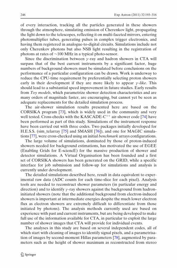
246 Exp Astron (2011) 32:193–316
of every interaction, tracking all the particles generated in these showersthrough the atmosphere, simulating emission of Cherenkov light, propagatingthe light down to the telescopes, reflecting it on multi-faceted mirrors, enteringphotomultiplier tubes, generating pulses in complex trigger electronics, andhaving them registered in analogue-to-digital circuits. Simulations include notonly Cherenkov photons but also NSB light resulting in the registration ofphotons at rates of ∼100 MHz in a typical photo-sensor.
Since the discrimination between γ -ray and hadron showers in CTA willsurpass that of the best current instruments by a significant factor, hugenumbers of background showers must be simulated before conclusions on theperformance of a particular configuration can be drawn. Work is underway toreduce the CPU-time requirement by preferentially selecting proton showersearly in their development if they are more likely to appear γ -like. Thisshould lead to a substantial speed improvement in future studies. Early resultsfrom Toy models, which parametrize shower detection characteristics and aremany orders of magnitude faster, are encouraging, but cannot yet be seen asadequate replacements for the detailed simulation process.
The air-shower simulation results presented here are based on theCORSIKA program [73], which is widely used in the community and verywell tested. Cross-checks with the KASCADE-C++ air-shower code [74] havebeen performed as part of this study. Simulations of the instrument responsehave been carried out with three codes. Two packages initially developed forH.E.S.S. (sim_telarray [75] and SMASH [76]), and one for MAGIC simula-tions [77], were cross-checked using an initial benchmark arrays configurations.
The large volume of simulations, dominated by those of proton-inducedshowers needed for background estimations, has motivated the use of EGEE(Enabling Grids for E-sciencE) for the massive production of shower anddetector simulations. A Virtual Organisation has been founded and a firstset of CORSIKA showers has been generated on the GRID, while a specificinterface for job submission and follow-up for simulations and analysis iscurrently under development.
The detailed simulations described here, result in data equivalent to exper-imental raw data (ADC counts for each time-slice for each pixel). Analysistools are needed to reconstruct shower parameters (in particular energy anddirection) and to identify γ -ray showers against the background from hadron-initiated showers (note that the additional background from electron-inducedshowers is important at intermediate energies despite the much lower electronflux as electron showers are extremely difficult to differentiate from thoseinitiated by photons). The analysis methods currently used are based onexperience with past and current instruments, but are being developed to makefull use of the information available for CTA, in particular to exploit the largenumber of shower images that CTA will provide for individual events.
The analyses in this study are based on several independent codes, all ofwhich start with cleaning of images to identify signal pixels, and a parametrisa-tion of images by second-moment Hillas parameters [78], augmented by para-meters such as the height of shower maximum as reconstructed from stereo
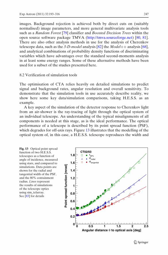
Exp Astron (2011) 32:193–316 247
images. Background rejection is achieved both by direct cuts on (suitablynormalised) image parameters, and more general multivariate analysis toolssuch as a Random Forest [79] classifier and Boosted Decision Trees within theopen source software package TMVA (http://tmva.sourceforge.net) [80, 81].There are also other analysis methods in use for the analysis of Cherenkovtelescope data, such as the 3-D-model analysis [82] the Model++ analysis [68],and analytical combinations of probability density functions of discriminatingvariables which have advantages over the standard second-moments analysisin at least some energy ranges. Some of these alternative methods have beenused for a subset of the studies presented here.
8.2 Verification of simulation tools
The optimisation of CTA relies heavily on detailed simulations to predictsignal and background rates, angular resolution and overall sensitivity. Todemonstrate that the simulation tools in use accurately describe reality, weshow here some key data/simulation comparisons, taking H.E.S.S. as anexample.
A key aspect of the simulation of the detector response to Cherenkov lightfrom an air-shower is the ray-tracing of light through the optical system ofan individual telescope. An understanding of the typical misalignments of allcomponents is needed at this stage, as is the ideal performance. The opticalperformance of a telescope is described by its point spread function (PSF),which degrades for off-axis rays. Figure 13 illustrates that the modelling of theoptical system of, in this case, a H.E.S.S. telescope reproduces the width and
Fig. 13 Optical point spreadfunction of two H.E.S.S.telescopes as a function ofangle of incidence, measuredusing stars, and compared tosimulations. Data points areshown for the radial andtangential width of the PSF,and the 80% containmentradius. Lines representthe results of simulationsof the telescope opticsusing sim_telarray.See [83] for details
to optical axis [deg]θAngular distance 0 0.5 1 1.5 2 2.5
Po
int
spre
ad f
un
ctio
n [
mra
d]
0
0.2
0.4
0.6
0.8
1
1.2
1.4
1.6
1.8CT02/03
80%rradialσtangentialσ
248 Exp Astron (2011) 32:193–316
Fig. 14 Comparison ofmeasured (black squares) andsimulated (red triangles andblue circles) image parametersfor the H.E.S.S. telescopes.Measured data are takenfrom a flare of the blazarPKS 2155-304 [84] for whichthe signal/noise ratio was veryhigh and large gamma-raystatistics are available
Impact Distance (m)0 50 100 150 200 250
rms
ang
ula
r si
ze (
deg
rees
)
0
0.05
0.1
0.15
0.2
0.25
0.3
Width
Length
Data
CORSIKA
KASKADE
shape of the PSF in all details, and that essentially identical imaging is achievedfor different telescopes in the system.
An end-to-end test of the correct simulation of gamma-ray induced showerscan be made using the signal from a strong source under very high sig-nal/background conditions. The giant flare from the blazar PKS 2155-304 ob-served with H.E.S.S. in 2006 provides an excellent opportunity for such a test.Figure 14 shows the satisfactory agreement (typically at the 5% level) betweenthe simulated and detected shape of the shower image as characterised by theirHillas width and length parameters. Gamma-ray showers were simulated withthe CORSIKA and KASKADE-C++ programs and have been passed throughone of the H.E.S.S. detector simulation and analysis chains. The measuredspectrum, optical efficiency, zenith angle and other runtime parameters wereused as inputs to this simulation.
In the analysis of experimental data, it is sufficient for simulations todescribe the characteristics of gamma-ray detection, since the cosmic-raybackground can (except for very diffuse sources) be modelled and subtractedusing measurements in regions without gamma-ray emission. However, for thedesign of new instruments, simulations must also provide a reliable modellingof all relevant backgrounds. Experience with existing systems shows that thisis indeed possible, provided that background events are simulated over avery wide area, up to an impact distance of around a kilometre from anytelescope and over a large solid angle, well beyond the direct field of viewof the instrument, so that far off-axis shower particles are properly included.
An inherent uncertainty in the simulation of the hadronic background isgiven by the currently limited knowledge of hadronic interaction processesat very high energies. The impact of this uncertainty on the Cherenkovlight profile has been studied using CORSIKA simulations with differentinteraction models. As can be seen in Fig. 15, the low energy (<80 GeV)models FLUKA [85] and UrQMD [86] do not exhibit significant differences,whereas the known discrepancy between the high-energy models QGSJet-

Exp Astron (2011) 32:193–316 249
distance from shower [m]0 20 40 60 80 100 120 140 160 180 200
p.e
.
10
11
12
13
14
15FLUKAUrQMD
distance from shower [m]0 20 40 60 80 100 120 140 160 180 200
p.e
.
30
35
40
45
50
55
60 FLUKA
UrQMD
distance from shower in [m]0 20 40 60 80 100 120 140 160 180 200
p.e
.
800
1000
1200
1400
1600
1800
2000
2200
QGSJet01
QGSJet II
distance from shower in [m]0 20 40 60 80 100 120 140 160 180 200
p.e
.
800
1000
1200
1400
1600
1800
2000
2200
QGSJet01Sibyll 2.1
Fig. 15 Comparison of the Cherenkov light profiles for proton-induced showers generated withdifferent hadronic interaction models. The profiles for FLUKA and UrQMD at 50 GeV (left) and100 GeV (right) are shown in the top panel. Two QGSJet versions and SIBYLL at 1 TeV arecompared in the bottom panels
01 [87], QGSJet-II [88, 89] and SIBYLL 2.1 [90] leads to an uncertainty ofabout 5% in the Cherenkov light profile at 1 TeV.
As can be seen in Fig. 16, the raw cosmic-ray detection rate as a functionof zenith angle is described to within about 20%. Given the uncertaintieson cosmic-ray flux, composition above the atmosphere and in the hadronicinteraction models, better agreement cannot be expected. In the background-limited regime this uncertainty corresponds to a 10% uncertainty in sensitivity,assuming that the fraction of γ -like events is understood. Figure 17 demon-strates that the fraction of such events, and the distributions of separationparameters, are indeed well understood for instruments such as H.E.S.S. usingthe simulation and analysis tools applied here to CTA.
8.3 Energy range and sensitivity of telescope arrays
Three methods of representing the sensitivity of a Cherenkov telescope areused in the following discussion. All three have merits and emphasise differentfeatures. The traditional way to represent the sensitivity of Cherenkov Tele-scope systems is in terms of integral sensitivity, including all events recon-structed above a given energy (and often multiplied by the threshold energy
250 Exp Astron (2011) 32:193–316
Fig. 16 Dependence ofH.E.S.S. system trigger rateon zenith angle, for data andsimulations. The simulationsassume two different modelatmospheres, with theatmosphere at the H.E.S.S.site representing anintermediate case. See[72] for more details
Cos (Zenith)0.3 0.4 0.5 0.6 0.7 0.8 0.9 1
Rat
e (H
z)
10
102
103
System Rate Multi-2
(Prediction Multi-2 Maritime)
(Prediction Multi-2 Desert)
Mean Single Telescope Rate
System Rate Multi-3
System Rate Multi-4
to flatten the curves and give more useful units of erg/(cm2s). An observationtime of 50 hours (typical for the first generation of IACTs) is assumed forcomparison to published sensitivity curves of historical and current instru-ments. Integral sensitivities depend on the assumed source spectrum andcan be deceptive in that much of the detection power quoted for a giventhreshold may actually be derived from events well above that threshold. A
Fig. 17 Measureddistribution of theproton/electron separationparameter ζ for 239 hours ofH.E.S.S. data on sky fieldswithout gamma emission,compared to simulations ofproton- and electron-inducedshowers. The shape of thebackground is very wellreproduced by simulationsacross the full range of ζ .Gamma-ray signals appearclose to ζ = 1. The electronbackground is thereforeimportant despite therelatively low flux of electronsin comparison to hadrons.See [91] for more details
ζ0.6 0.65 0.7 0.75 0.8 0.85 0.9 0.95 1
Eve
nts
100
200
300
400
500
600
700
800
900
0 0.2 0.4 0.6 0.8 1
210
310
410
510
610
0.6 0.8 10
20
40
60
80
100
120 HESS 1-4 TeV
Electrons
Protons
Best Fit Model
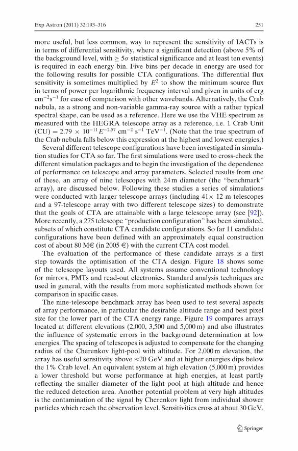
Exp Astron (2011) 32:193–316 251
more useful, but less common, way to represent the sensitivity of IACTs isin terms of differential sensitivity, where a significant detection (above 5% ofthe background level, with ≥ 5σ statistical significance and at least ten events)is required in each energy bin. Five bins per decade in energy are used forthe following results for possible CTA configurations. The differential fluxsensitivity is sometimes multiplied by E2 to show the minimum source fluxin terms of power per logarithmic frequency interval and given in units of ergcm−2s−1 for ease of comparison with other wavebands. Alternatively, the Crabnebula, as a strong and non-variable gamma-ray source with a rather typicalspectral shape, can be used as a reference. Here we use the VHE spectrum asmeasured with the HEGRA telescope array as a reference, i.e. 1 Crab Unit(CU) = 2.79 × 10⁻¹¹ E−2.57 cm−2 s−1 TeV−1. (Note that the true spectrum ofthe Crab nebula falls below this expression at the highest and lowest energies.)
Several different telescope configurations have been investigated in simula-tion studies for CTA so far. The first simulations were used to cross-check thedifferent simulation packages and to begin the investigation of the dependenceof performance on telescope and array parameters. Selected results from oneof these, an array of nine telescopes with 24 m diameter (the “benchmark”array), are discussed below. Following these studies a series of simulationswere conducted with larger telescope arrays (including 41× 12 m telescopesand a 97-telescope array with two different telescope sizes) to demonstratethat the goals of CTA are attainable with a large telescope array (see [92]).More recently, a 275 telescope “production configuration” has been simulated,subsets of which constitute CTA candidate configurations. So far 11 candidateconfigurations have been defined with an approximately equal constructioncost of about 80 Me (in 2005 e) with the current CTA cost model.
The evaluation of the performance of these candidate arrays is a firststep towards the optimisation of the CTA design. Figure 18 shows someof the telescope layouts used. All systems assume conventional technologyfor mirrors, PMTs and read-out electronics. Standard analysis techniques areused in general, with the results from more sophisticated methods shown forcomparison in specific cases.
The nine-telescope benchmark array has been used to test several aspectsof array performance, in particular the desirable altitude range and best pixelsize for the lower part of the CTA energy range. Figure 19 compares arrayslocated at different elevations (2,000, 3,500 and 5,000 m) and also illustratesthe influence of systematic errors in the background determination at lowenergies. The spacing of telescopes is adjusted to compensate for the changingradius of the Cherenkov light-pool with altitude. For 2,000 m elevation, thearray has useful sensitivity above ≈20 GeV and at higher energies dips belowthe 1% Crab level. An equivalent system at high elevation (5,000 m) providesa lower threshold but worse performance at high energies, at least partlyreflecting the smaller diameter of the light pool at high altitude and hencethe reduced detection area. Another potential problem at very high altitudesis the contamination of the signal by Cherenkov light from individual showerparticles which reach the observation level. Sensitivities cross at about 30 GeV,
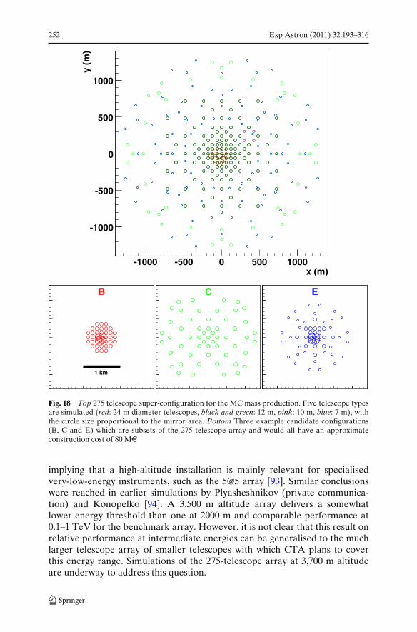
252 Exp Astron (2011) 32:193–316
x (m)-1000 -500 0 500 1000
y (m
)
-1000
-500
0
500
1000
B
1 km
C E
Fig. 18 Top 275 telescope super-configuration for the MC mass production. Five telescope typesare simulated (red: 24 m diameter telescopes, black and green: 12 m, pink: 10 m, blue: 7 m), withthe circle size proportional to the mirror area. Bottom Three example candidate configurations(B, C and E) which are subsets of the 275 telescope array and would all have an approximateconstruction cost of 80 Me
implying that a high-altitude installation is mainly relevant for specialisedvery-low-energy instruments, such as the 5@5 array [93]. Similar conclusionswere reached in earlier simulations by Plyasheshnikov (private communica-tion) and Konopelko [94]. A 3,500 m altitude array delivers a somewhatlower energy threshold than one at 2000 m and comparable performance at0.1–1 TeV for the benchmark array. However, it is not clear that this result onrelative performance at intermediate energies can be generalised to the muchlarger telescope array of smaller telescopes with which CTA plans to coverthis energy range. Simulations of the 275-telescope array at 3,700 m altitudeare underway to address this question.
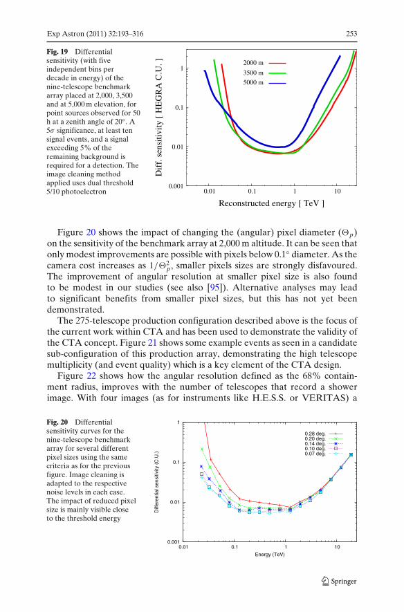
Exp Astron (2011) 32:193–316 253
Fig. 19 Differentialsensitivity (with fiveindependent bins perdecade in energy) of thenine-telescope benchmarkarray placed at 2,000, 3,500and at 5,000 m elevation, forpoint sources observed for 50h at a zenith angle of 20◦. A5σ significance, at least tensignal events, and a signalexceeding 5% of theremaining background isrequired for a detection. Theimage cleaning methodapplied uses dual threshold5/10 photoelectron
0.001
0.01
0.1
1
0.01 0.1 1 10
Dif
f. s
ensi
tivity
[ H
EG
RA
C.U
. ]
Reconstructed energy [ TeV ]
2000 m
3500 m
5000 m
Figure 20 shows the impact of changing the (angular) pixel diameter (�p)on the sensitivity of the benchmark array at 2,000 m altitude. It can be seen thatonly modest improvements are possible with pixels below 0.1◦ diameter. As thecamera cost increases as 1/�2
p, smaller pixels sizes are strongly disfavoured.The improvement of angular resolution at smaller pixel size is also foundto be modest in our studies (see also [95]). Alternative analyses may leadto significant benefits from smaller pixel sizes, but this has not yet beendemonstrated.
The 275-telescope production configuration described above is the focus ofthe current work within CTA and has been used to demonstrate the validity ofthe CTA concept. Figure 21 shows some example events as seen in a candidatesub-configuration of this production array, demonstrating the high telescopemultiplicity (and event quality) which is a key element of the CTA design.
Figure 22 shows how the angular resolution defined as the 68% contain-ment radius, improves with the number of telescopes that record a showerimage. With four images (as for instruments like H.E.S.S. or VERITAS) a
Fig. 20 Differentialsensitivity curves for thenine-telescope benchmarkarray for several differentpixel sizes using the samecriteria as for the previousfigure. Image cleaning isadapted to the respectivenoise levels in each case.The impact of reduced pixelsize is mainly visible closeto the threshold energy
0.001
0.01
0.1
1
0.01 0.1 1 10
Diff
eren
tial s
ensi
tivity
(C
.U.)
Energy (TeV)
0.28 deg.0.20 deg.0.14 deg.0.10 deg.0.07 deg.
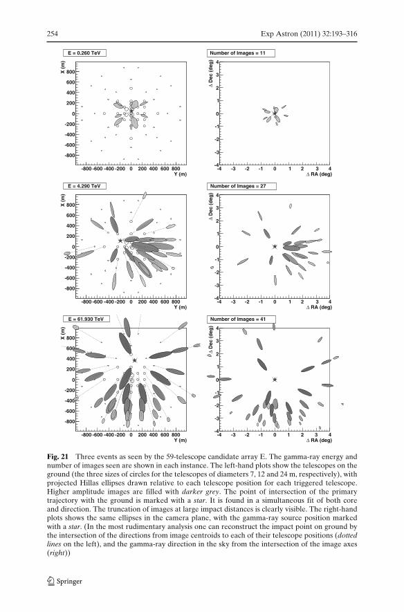
254 Exp Astron (2011) 32:193–316
Y (m)-800 -600 -400 -200 0 200 400 600 800
X (
m)
-800
-600
-400
-200
0
200
400
600
800
E = 0.260 TeV
RA (deg)Δ-4 -3 -2 -1 0 1 2 3 4
Dec
(d
eg)
Δ
-4
-3
-2
-1
0
1
2
3
4
Number of Images = 11
Y (m)-800 -600 -400 -200 0 200 400 600 800
X (
m)
-800
-600
-400
-200
0
200
400
600
800
E = 4.290 TeV
RA (deg)Δ-4 -3 -2 -1 0 1 2 3 4
Dec
(d
eg)
Δ
-4
-3
-2
-1
0
1
2
3
4
Number of Images = 27
Y (m)-800 -600 -400 -200 0 200 400 600 800
X (
m)
-800
-600
-400
-200
0
200
400
600
800
E = 61.930 TeV
RA (deg)Δ-4 -3 -2 -1 0 1 2 3 4
Dec
(d
eg)
Δ
-4
-3
-2
-1
0
1
2
3
4
Number of Images = 41
Fig. 21 Three events as seen by the 59-telescope candidate array E. The gamma-ray energy andnumber of images seen are shown in each instance. The left-hand plots show the telescopes on theground (the three sizes of circles for the telescopes of diameters 7, 12 and 24 m, respectively), withprojected Hillas ellipses drawn relative to each telescope position for each triggered telescope.Higher amplitude images are filled with darker grey. The point of intersection of the primarytrajectory with the ground is marked with a star. It is found in a simultaneous fit of both coreand direction. The truncation of images at large impact distances is clearly visible. The right-handplots shows the same ellipses in the camera plane, with the gamma-ray source position markedwith a star. (In the most rudimentary analysis one can reconstruct the impact point on ground bythe intersection of the directions from image centroids to each of their telescope positions (dottedlines on the left), and the gamma-ray direction in the sky from the intersection of the image axes(right))
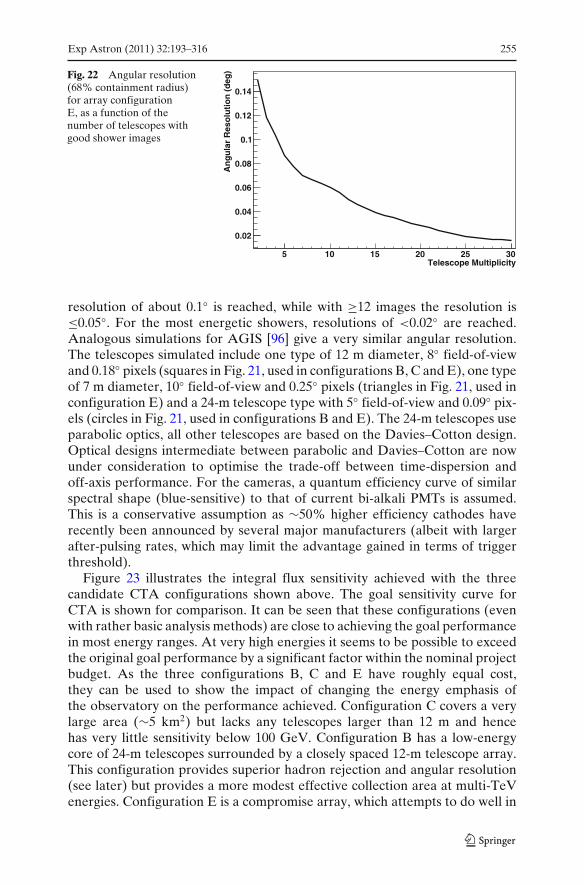
Exp Astron (2011) 32:193–316 255
Fig. 22 Angular resolution(68% containment radius)for array configurationE, as a function of thenumber of telescopes withgood shower images
Telescope Multiplicity5 10 15 20 25 30
An
gu
lar
Res
olu
tio
n (
deg
)0.02
0.04
0.06
0.08
0.1
0.12
0.14
resolution of about 0.1◦ is reached, while with ≥12 images the resolution is≤0.05◦. For the most energetic showers, resolutions of <0.02◦ are reached.Analogous simulations for AGIS [96] give a very similar angular resolution.The telescopes simulated include one type of 12 m diameter, 8◦ field-of-viewand 0.18◦ pixels (squares in Fig. 21, used in configurations B, C and E), one typeof 7 m diameter, 10◦ field-of-view and 0.25◦ pixels (triangles in Fig. 21, used inconfiguration E) and a 24-m telescope type with 5◦ field-of-view and 0.09◦ pix-els (circles in Fig. 21, used in configurations B and E). The 24-m telescopes useparabolic optics, all other telescopes are based on the Davies–Cotton design.Optical designs intermediate between parabolic and Davies–Cotton are nowunder consideration to optimise the trade-off between time-dispersion andoff-axis performance. For the cameras, a quantum efficiency curve of similarspectral shape (blue-sensitive) to that of current bi-alkali PMTs is assumed.This is a conservative assumption as ∼50% higher efficiency cathodes haverecently been announced by several major manufacturers (albeit with largerafter-pulsing rates, which may limit the advantage gained in terms of triggerthreshold).
Figure 23 illustrates the integral flux sensitivity achieved with the threecandidate CTA configurations shown above. The goal sensitivity curve forCTA is shown for comparison. It can be seen that these configurations (evenwith rather basic analysis methods) are close to achieving the goal performancein most energy ranges. At very high energies it seems to be possible to exceedthe original goal performance by a significant factor within the nominal projectbudget. As the three configurations B, C and E have roughly equal cost,they can be used to show the impact of changing the energy emphasis ofthe observatory on the performance achieved. Configuration C covers a verylarge area (∼5 km2) but lacks any telescopes larger than 12 m and hencehas very little sensitivity below 100 GeV. Configuration B has a low-energycore of 24-m telescopes surrounded by a closely spaced 12-m telescope array.This configuration provides superior hadron rejection and angular resolution(see later) but provides a more modest effective collection area at multi-TeVenergies. Configuration E is a compromise array, which attempts to do well in
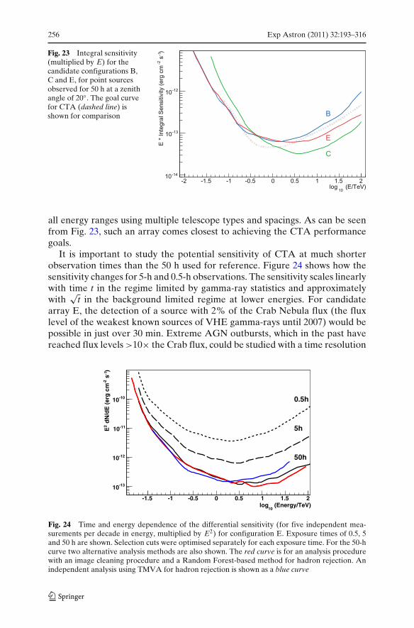
256 Exp Astron (2011) 32:193–316
Fig. 23 Integral sensitivity(multiplied by E) for thecandidate configurations B,C and E, for point sourcesobserved for 50 h at a zenithangle of 20◦. The goal curvefor CTA (dashed line) isshown for comparison
all energy ranges using multiple telescope types and spacings. As can be seenfrom Fig. 23, such an array comes closest to achieving the CTA performancegoals.
It is important to study the potential sensitivity of CTA at much shorterobservation times than the 50 h used for reference. Figure 24 shows how thesensitivity changes for 5-h and 0.5-h observations. The sensitivity scales linearlywith time t in the regime limited by gamma-ray statistics and approximatelywith
√t in the background limited regime at lower energies. For candidate
array E, the detection of a source with 2% of the Crab Nebula flux (the fluxlevel of the weakest known sources of VHE gamma-rays until 2007) would bepossible in just over 30 min. Extreme AGN outbursts, which in the past havereached flux levels >10× the Crab flux, could be studied with a time resolution
(Energy/TeV)10
log-1.5 -1 -0.5 0 0.5 1 1.5 2
)-1
s-2
dN
/dE
(er
g c
m2
E
-1310
-1210
-1110
-1010 0.5h
5h
50h
Fig. 24 Time and energy dependence of the differential sensitivity (for five independent mea-surements per decade in energy, multiplied by E2) for configuration E. Exposure times of 0.5, 5and 50 h are shown. Selection cuts were optimised separately for each exposure time. For the 50-hcurve two alternative analysis methods are also shown. The red curve is for an analysis procedurewith an image cleaning procedure and a Random Forest-based method for hadron rejection. Anindependent analysis using TMVA for hadron rejection is shown as a blue curve
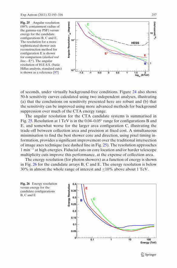
Exp Astron (2011) 32:193–316 257
Fig. 25 Angular resolution(68% containment radius ofthe gamma-ray PSF) versusenergy for the candidateconfigurations B, C and E.The resolution for a moresophisticated shower axisreconstruction method forconfiguration E is shownfor comparison (dashed redline—E*). The angularresolution of H.E.S.S. (basicHillas analysis, standard cuts)is shown as a reference [97]
(E/TeV)10
log-1.5 -1 -0.5 0 0.5 1 1.5 2
(d
egre
es)
68A
ng
ula
r R
eso
luti
on
r-210
-110
(ar
cmin
ute
s)68r
1
10
C
B
EE*
HESS
of seconds, under virtually background-free conditions. Figure 24 also shows50-h sensitivity curves calculated using two independent analyses, illustrating(a) that the conclusions on sensitivity presented here are robust and (b) thatthe sensitivity can be improved using more advanced methods for backgroundsuppression over much of the CTA energy range.
The angular resolution for the CTA candidate systems is summarised inFig. 25. Resolution at 1 TeV is in the 0.04–0.05◦ range for configurations B andE, and somewhat worse for the larger area configuration C, illustrating thetrade-off between collection area and precision at fixed cost. A simultaneousminimisation to find the best shower core and direction, using pixel timing in-formation, provides a significant improvement over the traditional intersectionof image axes technique (see dashed line in Fig. 25). The resolution approaches1 min−1 at high energies. Fiducial cuts on core location and/or harder telescopemultiplicity cuts improve this performance, at the expense of collection area.
The energy resolution (for photon showers) as a function of energy is shownin Fig. 26 for the candidate arrays B, C and E. The energy resolution is below30% in almost the whole range of interest and ≤10% above about 1 TeV.
Fig. 26 Energy resolutionversus energy for thecandidate configurationsB, C and E
Energy (TeV)0.1 1 10 100
En
erg
y R
eso
luti
on
0
0.05
0.1
0.15
0.2
0.25
0.3
0.35
0.4
B
E
C
258 Exp Astron (2011) 32:193–316
In summary, whilst the final optimisation of the CTA design will requireaccurate cost models and input from quantitative “key science projects”, itis clear from our current studies that an array of ∼60 wide field of viewCherenkov telescopes can achieve the key performance goals of CTA withinthe envisaged level of investment.
9 CTA telescope technology
A particular size of Cherenkov telescope is only optimal for covering about1.5–2 decades in energy. Three sizes of telescope are therefore needed to coverthe large energy range CTA proposes to study (from a few tens of GeV toabove 100 TeV). The current baseline design consists of three single-mirrortelescopes: SST: Small size telescopes of 5–8 m diameter; MST: Medium sizetelescopes of 10–12 m diameter; and LST: Large size telescopes of 20–30 mdiameter.
While telescope optics involving multiple reflectors or optical correctorshave been proposed [66, 98, 99] and do provide improved and more uniformimaging across large fields of view, these designs are also more complicatedthan the classical single-reflector Cherenkov telescopes. Single-reflector de-signs are adequate for the fields of view necessary for CTA and provide aPSF well-matched to the proposed PMT-based camera. Imaging is improvedby choosing relatively large f/d values, in the range of 1.2–1.5. A secondvariable is the dish shape: a Davies–Cotton layout provides good imaging overwide fields, but introduce a time dispersion. For small dish diameters thisdispersion is smaller than the intrinsic width of the photon distribution, andtherefore insignificant. For large dish diameters, the difference in photon pathlength from different parts of the reflector becomes larger than the intrinsicspread of photon arrival times, broadening the light pulse. A parabolic shape,which does not introduce this dispersion, is therefore preferred for very largetelescopes. The transition between the two regimes is at about the size of theMST. Other alternative dish shapes face the same general trade-off betweentime dispersion and imaging quality.
9.1 Telescope mount and dish
One of the most important mechanical components of a telescope is the mount,with its associated drive systems. This must allow the slewing of the dish andthe tracking of celestial objects. The dish structure supports the segmentedreflector and the camera support which holds the camera at the focus onthe reflector. Critical properties for the structural components of a telescopeinclude:
Positioning of mirror facets. The dish structure supports mirror facets forminga parabolic or Davies–Cotton reflector. Its prime task is to keep therelative orientation of the mirror facets stable at the arcminute level.
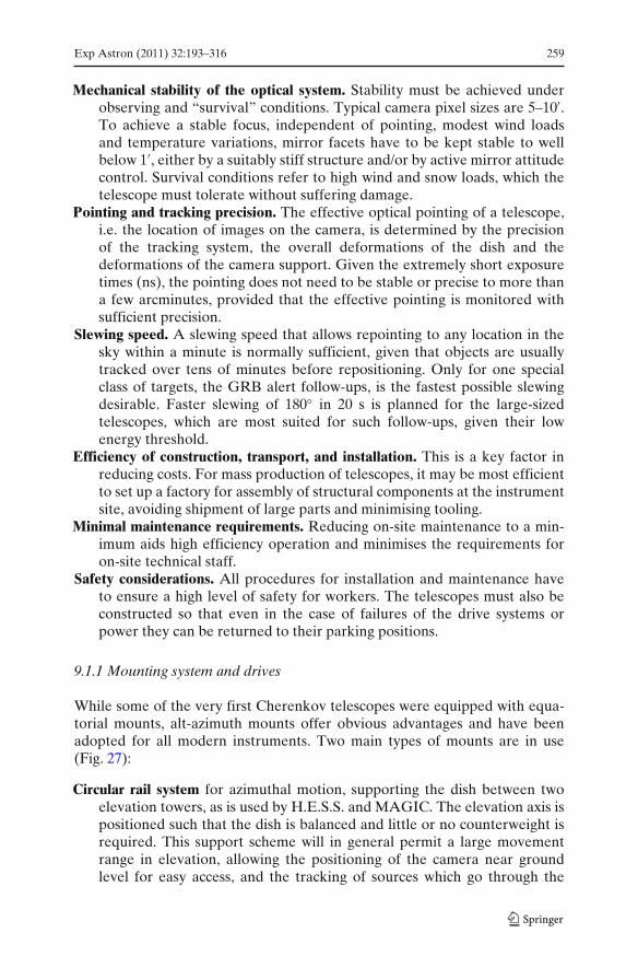
Exp Astron (2011) 32:193–316 259
Mechanical stability of the optical system. Stability must be achieved underobserving and “survival” conditions. Typical camera pixel sizes are 5–10′.To achieve a stable focus, independent of pointing, modest wind loadsand temperature variations, mirror facets have to be kept stable to wellbelow 1′, either by a suitably stiff structure and/or by active mirror attitudecontrol. Survival conditions refer to high wind and snow loads, which thetelescope must tolerate without suffering damage.
Pointing and tracking precision. The effective optical pointing of a telescope,i.e. the location of images on the camera, is determined by the precisionof the tracking system, the overall deformations of the dish and thedeformations of the camera support. Given the extremely short exposuretimes (ns), the pointing does not need to be stable or precise to more thana few arcminutes, provided that the effective pointing is monitored withsufficient precision.
Slewing speed. A slewing speed that allows repointing to any location in thesky within a minute is normally sufficient, given that objects are usuallytracked over tens of minutes before repositioning. Only for one specialclass of targets, the GRB alert follow-ups, is the fastest possible slewingdesirable. Faster slewing of 180◦ in 20 s is planned for the large-sizedtelescopes, which are most suited for such follow-ups, given their lowenergy threshold.
Efficiency of construction, transport, and installation. This is a key factor inreducing costs. For mass production of telescopes, it may be most efficientto set up a factory for assembly of structural components at the instrumentsite, avoiding shipment of large parts and minimising tooling.
Minimal maintenance requirements. Reducing on-site maintenance to a min-imum aids high efficiency operation and minimises the requirements foron-site technical staff.
Safety considerations. All procedures for installation and maintenance haveto ensure a high level of safety for workers. The telescopes must also beconstructed so that even in the case of failures of the drive systems orpower they can be returned to their parking positions.
9.1.1 Mounting system and drives
While some of the very first Cherenkov telescopes were equipped with equa-torial mounts, alt-azimuth mounts offer obvious advantages and have beenadopted for all modern instruments. Two main types of mounts are in use(Fig. 27):
Circular rail system for azimuthal motion, supporting the dish between twoelevation towers, as is used by H.E.S.S. and MAGIC. The elevation axis ispositioned such that the dish is balanced and little or no counterweight isrequired. This support scheme will in general permit a large movementrange in elevation, allowing the positioning of the camera near groundlevel for easy access, and the tracking of sources which go through the
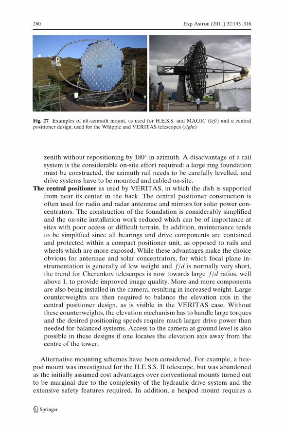
260 Exp Astron (2011) 32:193–316
Fig. 27 Examples of alt-azimuth mount, as used for H.E.S.S. and MAGIC (left) and a centralpositioner design, used for the Whipple and VERITAS telescopes (right)
zenith without repositioning by 180◦ in azimuth. A disadvantage of a railsystem is the considerable on-site effort required: a large ring foundationmust be constructed, the azimuth rail needs to be carefully levelled, anddrive systems have to be mounted and cabled on-site.
The central positioner as used by VERITAS, in which the dish is supportedfrom near its center in the back. The central positioner construction isoften used for radio and radar antennae and mirrors for solar power con-centrators. The construction of the foundation is considerably simplifiedand the on-site installation work reduced which can be of importance atsites with poor access or difficult terrain. In addition, maintenance tendsto be simplified since all bearings and drive components are containedand protected within a compact positioner unit, as opposed to rails andwheels which are more exposed. While these advantages make the choiceobvious for antennae and solar concentrators, for which focal plane in-strumentation is generally of low weight and f/d is normally very short,the trend for Cherenkov telescopes is now towards large f/d ratios, wellabove 1, to provide improved image quality. More and more componentsare also being installed in the camera, resulting in increased weight. Largecounterweights are then required to balance the elevation axis in thecentral positioner design, as is visible in the VERITAS case. Withoutthese counterweights, the elevation mechanism has to handle large torquesand the desired positioning speeds require much larger drive power thanneeded for balanced systems. Access to the camera at ground level is alsopossible in these designs if one locates the elevation axis away from thecentre of the tower.
Alternative mounting schemes have been considered. For example, a hex-pod mount was investigated for the H.E.S.S. II telescope, but was abandonedas the initially assumed cost advantages over conventional mounts turned outto be marginal due to the complexity of the hydraulic drive system and theextensive safety features required. In addition, a hexpod mount requires a
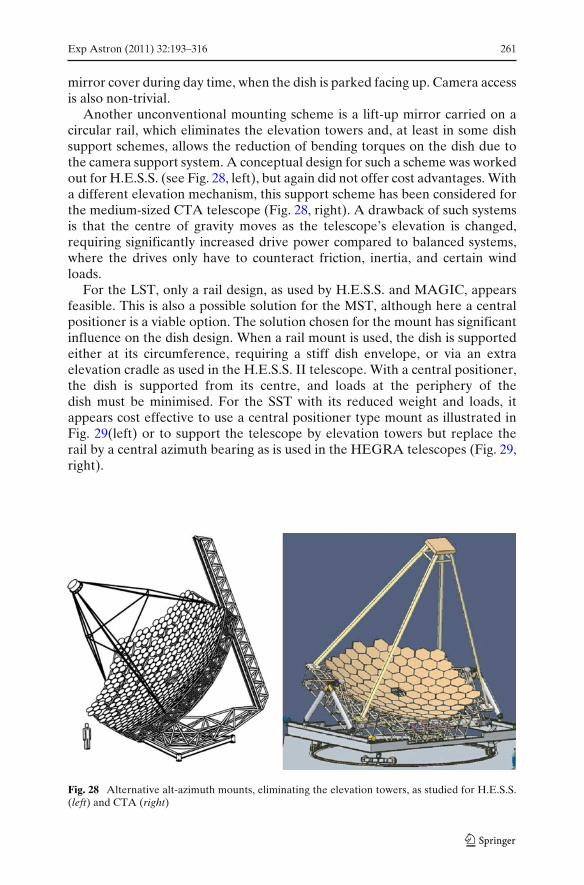
Exp Astron (2011) 32:193–316 261
mirror cover during day time, when the dish is parked facing up. Camera accessis also non-trivial.
Another unconventional mounting scheme is a lift-up mirror carried on acircular rail, which eliminates the elevation towers and, at least in some dishsupport schemes, allows the reduction of bending torques on the dish due tothe camera support system. A conceptual design for such a scheme was workedout for H.E.S.S. (see Fig. 28, left), but again did not offer cost advantages. Witha different elevation mechanism, this support scheme has been considered forthe medium-sized CTA telescope (Fig. 28, right). A drawback of such systemsis that the centre of gravity moves as the telescope’s elevation is changed,requiring significantly increased drive power compared to balanced systems,where the drives only have to counteract friction, inertia, and certain windloads.
For the LST, only a rail design, as used by H.E.S.S. and MAGIC, appearsfeasible. This is also a possible solution for the MST, although here a centralpositioner is a viable option. The solution chosen for the mount has significantinfluence on the dish design. When a rail mount is used, the dish is supportedeither at its circumference, requiring a stiff dish envelope, or via an extraelevation cradle as used in the H.E.S.S. II telescope. With a central positioner,the dish is supported from its centre, and loads at the periphery of thedish must be minimised. For the SST with its reduced weight and loads, itappears cost effective to use a central positioner type mount as illustrated inFig. 29(left) or to support the telescope by elevation towers but replace therail by a central azimuth bearing as is used in the HEGRA telescopes (Fig. 29,right).
Fig. 28 Alternative alt-azimuth mounts, eliminating the elevation towers, as studied for H.E.S.S.(left) and CTA (right)
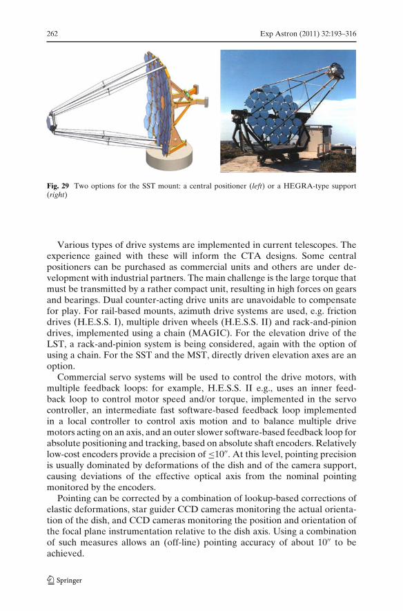
262 Exp Astron (2011) 32:193–316
Fig. 29 Two options for the SST mount: a central positioner (left) or a HEGRA-type support(right)
Various types of drive systems are implemented in current telescopes. Theexperience gained with these will inform the CTA designs. Some centralpositioners can be purchased as commercial units and others are under de-velopment with industrial partners. The main challenge is the large torque thatmust be transmitted by a rather compact unit, resulting in high forces on gearsand bearings. Dual counter-acting drive units are unavoidable to compensatefor play. For rail-based mounts, azimuth drive systems are used, e.g. frictiondrives (H.E.S.S. I), multiple driven wheels (H.E.S.S. II) and rack-and-piniondrives, implemented using a chain (MAGIC). For the elevation drive of theLST, a rack-and-pinion system is being considered, again with the option ofusing a chain. For the SST and the MST, directly driven elevation axes are anoption.
Commercial servo systems will be used to control the drive motors, withmultiple feedback loops: for example, H.E.S.S. II e.g., uses an inner feed-back loop to control motor speed and/or torque, implemented in the servocontroller, an intermediate fast software-based feedback loop implementedin a local controller to control axis motion and to balance multiple drivemotors acting on an axis, and an outer slower software-based feedback loop forabsolute positioning and tracking, based on absolute shaft encoders. Relativelylow-cost encoders provide a precision of ≤10′′. At this level, pointing precisionis usually dominated by deformations of the dish and of the camera support,causing deviations of the effective optical axis from the nominal pointingmonitored by the encoders.
Pointing can be corrected by a combination of lookup-based corrections ofelastic deformations, star guider CCD cameras monitoring the actual orienta-tion of the dish, and CCD cameras monitoring the position and orientation ofthe focal plane instrumentation relative to the dish axis. Using a combinationof such measures allows an (off-line) pointing accuracy of about 10′′ to beachieved.
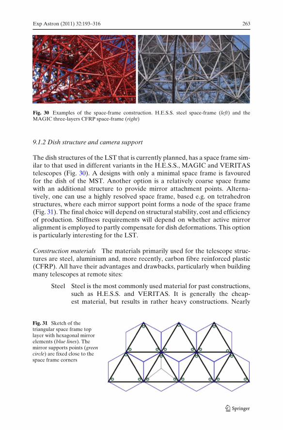
Exp Astron (2011) 32:193–316 263
Fig. 30 Examples of the space-frame construction. H.E.S.S. steel space-frame (left) and theMAGIC three-layers CFRP space-frame (right)
9.1.2 Dish structure and camera support
The dish structures of the LST that is currently planned, has a space frame sim-ilar to that used in different variants in the H.E.S.S., MAGIC and VERITAStelescopes (Fig. 30). A designs with only a minimal space frame is favouredfor the dish of the MST. Another option is a relatively coarse space framewith an additional structure to provide mirror attachment points. Alterna-tively, one can use a highly resolved space frame, based e.g. on tetrahedronstructures, where each mirror support point forms a node of the space frame(Fig. 31). The final choice will depend on structural stability, cost and efficiencyof production. Stiffness requirements will depend on whether active mirroralignment is employed to partly compensate for dish deformations. This optionis particularly interesting for the LST.
Construction materials The materials primarily used for the telescope struc-tures are steel, aluminium and, more recently, carbon fibre reinforced plastic(CFRP). All have their advantages and drawbacks, particularly when buildingmany telescopes at remote sites:
Steel Steel is the most commonly used material for past constructions,such as H.E.S.S. and VERITAS. It is generally the cheap-est material, but results in rather heavy constructions. Nearly
Fig. 31 Sketch of thetriangular space frame toplayer with hexagonal mirrorelements (blue lines). Themirror supports points (greencircle) are fixed close to thespace frame corners
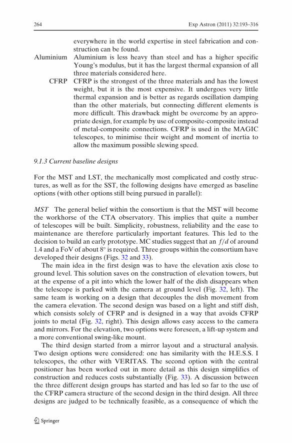
264 Exp Astron (2011) 32:193–316
everywhere in the world expertise in steel fabrication and con-struction can be found.
Aluminium Aluminium is less heavy than steel and has a higher specificYoung’s modulus, but it has the largest thermal expansion of allthree materials considered here.
CFRP CFRP is the strongest of the three materials and has the lowestweight, but it is the most expensive. It undergoes very littlethermal expansion and is better as regards oscillation dampingthan the other materials, but connecting different elements ismore difficult. This drawback might be overcome by an appro-priate design, for example by use of composite-composite insteadof metal-composite connections. CFRP is used in the MAGICtelescopes, to minimise their weight and moment of inertia toallow the maximum possible slewing speed.
9.1.3 Current baseline designs
For the MST and LST, the mechanically most complicated and costly struc-tures, as well as for the SST, the following designs have emerged as baselineoptions (with other options still being pursued in parallel):
MST The general belief within the consortium is that the MST will becomethe workhorse of the CTA observatory. This implies that quite a numberof telescopes will be built. Simplicity, robustness, reliability and the ease tomaintenance are therefore particularly important features. This led to thedecision to build an early prototype. MC studies suggest that an f/d of around1.4 and a FoV of about 8◦ is required. Three groups within the consortium havedeveloped their designs (Figs. 32 and 33).
The main idea in the first design was to have the elevation axis close toground level. This solution saves on the construction of elevation towers, butat the expense of a pit into which the lower half of the dish disappears whenthe telescope is parked with the camera at ground level (Fig. 32, left). Thesame team is working on a design that decouples the dish movement fromthe camera elevation. The second design was based on a light and stiff dish,which consists solely of CFRP and is designed in a way that avoids CFRPjoints to metal (Fig. 32, right). This design allows easy access to the cameraand mirrors. For the elevation, two options were foreseen, a lift-up system anda more conventional swing-like mount.
The third design started from a mirror layout and a structural analysis.Two design options were considered: one has similarity with the H.E.S.S. Itelescopes, the other with VERITAS. The second option with the centralpositioner has been worked out in more detail as this design simplifies ofconstruction and reduces costs substantially (Fig. 33). A discussion betweenthe three different design groups has started and has led so far to the use ofthe CFRP camera structure of the second design in the third design. All threedesigns are judged to be technically feasible, as a consequence of which the
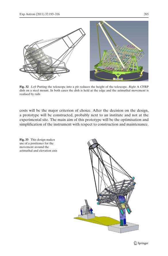
Exp Astron (2011) 32:193–316 265
Fig. 32 Left Putting the telescope into a pit reduces the height of the telescope. Right A CFRPdish on a steel mount. In both cases the dish is held at the edge and the azimuthal movement isrealised by rails
costs will be the major criterion of choice. After the decision on the design,a prototype will be constructed, probably next to an institute and not at theexperimental site. The main aim of this prototype will be the optimisation andsimplification of the instrument with respect to construction and maintenance.
Fig. 33 This design makesuse of a positioner for themovement around theazimuthal and elevation axis

266 Exp Astron (2011) 32:193–316
Fig. 34 Model of an AGISSchwarzschild–Coudertelescope and its two-mirroraplanatic optical system(from [96])
In parallel with the prototyping of the single-mirror MST, the design ofa Schwarzschild–Couder telescope for AGIS has progressed (see Fig. 34)and work towards prototyping of components and ultimately a full MST-SCprototype is underway in the US.
LST For the LST, the current baseline design consists of a parabolic dishof 23 m diameter with f/d = 1.2 constructed using carbon fibre structure (anenlarged derivative of the proven MAGIC design). The goal is to keep thetotal weight around 50 t (Fig. 35). The dish uses a 3- or 4-layer space frame,based on triangular elements, with hexagonal mirrors supported from some ofthe nodes of the space frame. The dish is supported by an alt-azimuth mountmoving on 6 bogeys along a circular rail.
SST For the SST, the mechanical design is less complex and several thereforetimescales are somewhat more relaxed. Several options are still under study.The large FoV that is essential for the SST results, for single-mirror designs,in a relatively large camera with high costs. In comparison, the structureof the small telescope is cheap. This large misbalance makes it sensible toinvestigate an SST with a secondary optics which can potentially significantlyreduce the camera cost, at the price of a more expensive mechanical structure.Whether this results is an overall saving is currently investigated. A possibledesign of a two-mirror system is shown in Fig. 36 (left). The design of a 6-mconventional telescope is pursued in parallel (Fig. 36, right). The costs of thesetwo fundamentally different concepts are now being evaluated. The result willdetermine which SST design will be selected.

Exp Astron (2011) 32:193–316 267
Fig. 35 Conceptual layout ofthe LST. The dish hasa diameter of 23 m
9.2 Telescope optics and mirror facets
9.2.1 Telescope optics
The reflector of each telescope images the Cherenkov light emitted by the airshowers onto the pixels of the photon detection system. Apart from the totalreflective area, which determines the amount of light that can be collected, theimportant parameters of the reflector system are:
The point spread function. The PSF quantifies how well the reflector concen-trates light from a point source. The RMS width of the PSF should be lessthan half the pixel diameter for 40% containment if centred on a pixel,(for a Gaussian PSF), or better than 1/3 of the pixel diameter for 68%containment.
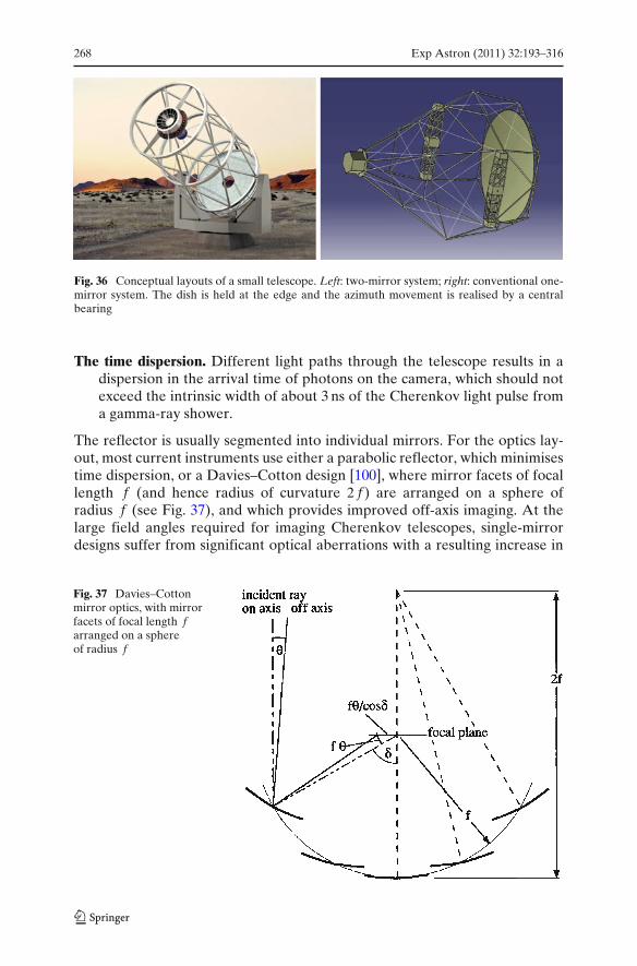
268 Exp Astron (2011) 32:193–316
Fig. 36 Conceptual layouts of a small telescope. Left: two-mirror system; right: conventional one-mirror system. The dish is held at the edge and the azimuth movement is realised by a centralbearing
The time dispersion. Different light paths through the telescope results in adispersion in the arrival time of photons on the camera, which should notexceed the intrinsic width of about 3 ns of the Cherenkov light pulse froma gamma-ray shower.
The reflector is usually segmented into individual mirrors. For the optics lay-out, most current instruments use either a parabolic reflector, which minimisestime dispersion, or a Davies–Cotton design [100], where mirror facets of focallength f (and hence radius of curvature 2 f ) are arranged on a sphere ofradius f (see Fig. 37), and which provides improved off-axis imaging. At thelarge field angles required for imaging Cherenkov telescopes, single-mirrordesigns suffer from significant optical aberrations with a resulting increase in
Fig. 37 Davies–Cottonmirror optics, with mirrorfacets of focal length farranged on a sphereof radius f
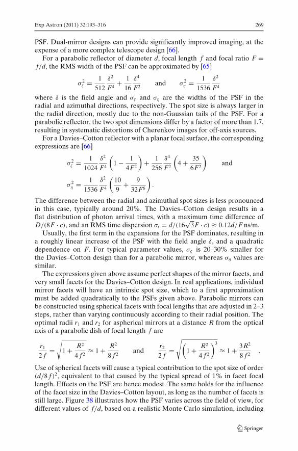
Exp Astron (2011) 32:193–316 269
PSF. Dual-mirror designs can provide significantly improved imaging, at theexpense of a more complex telescope design [66].
For a parabolic reflector of diameter d, focal length f and focal ratio F =f/d, the RMS width of the PSF can be approximated by [65]
σ 2ζ = 1
512
δ2
F4+ 1
16
δ4
F2and σ 2
η = 1
1536
δ2
F4
where δ is the field angle and σζ and ση are the widths of the PSF in theradial and azimuthal directions, respectively. The spot size is always larger inthe radial direction, mostly due to the non-Gaussian tails of the PSF. For aparabolic reflector, the two spot dimensions differ by a factor of more than 1.7,resulting in systematic distortions of Cherenkov images for off-axis sources.
For a Davies–Cotton reflector with a planar focal surface, the correspondingexpressions are [66]
σ 2ζ = 1
1024
δ2
F4
(1 − 1
4F2
)+ 1
256
δ4
F2
(4 + 35
6F2
)and
σ 2η = 1
1536
δ2
F4
(10
9+ 9
32F6
).
The difference between the radial and azimuthal spot sizes is less pronouncedin this case, typically around 20%. The Davies–Cotton design results in aflat distribution of photon arrival times, with a maximum time difference ofD/(8F · c), and an RMS time dispersion σt = d/(16
√3F · c) ≈ 0.12d/F ns/m.
Usually, the first term in the expansions for the PSF dominates, resulting ina roughly linear increase of the PSF with the field angle δ, and a quadraticdependence on F. For typical parameter values, σζ is 20–30% smaller forthe Davies–Cotton design than for a parabolic mirror, whereas ση values aresimilar.
The expressions given above assume perfect shapes of the mirror facets, andvery small facets for the Davies–Cotton design. In real applications, individualmirror facets will have an intrinsic spot size, which to a first approximationmust be added quadratically to the PSFs given above. Parabolic mirrors canbe constructed using spherical facets with focal lengths that are adjusted in 2–3steps, rather than varying continuously according to their radial position. Theoptimal radii r1 and r2 for aspherical mirrors at a distance R from the opticalaxis of a parabolic dish of focal length f are
r1
2 f=
√
1 + R2
4 f 2≈ 1 + R2
8 f 2and
r2
2 f=
√(1 + R2
4 f 2
)3
≈ 1 + 3R2
8 f 2.
Use of spherical facets will cause a typical contribution to the spot size of order(d/8 f )2, equivalent to that caused by the typical spread of 1% in facet focallength. Effects on the PSF are hence modest. The same holds for the influenceof the facet size in the Davies–Cotton layout, as long as the number of facets isstill large. Figure 38 illustrates how the PSF varies across the field of view, fordifferent values of f/d, based on a realistic Monte Carlo simulation, including
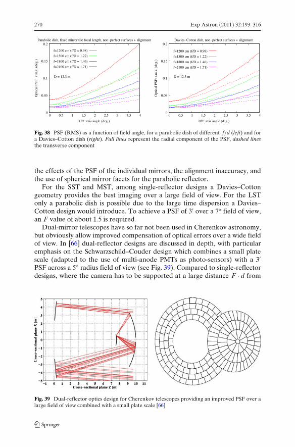
270 Exp Astron (2011) 32:193–316
f=1200 cm (f/D = 0.98)
f=1500 cm (f/D = 1.22)
f=1800 cm (f/D = 1.46)
f=2100 cm (f/D = 1.71)
0
0.05
0.1
0.15
0.2
0 0.5 1 1.5 2 2.5 3 3.5 4
Parabolic dish, fixed mirror tile focal length, non_perfect surfaces + alignmentO
ptic
al P
SF:
r.m
.s. (
deg.
)
D = 12.3 m
Off_axis angle (deg.)
f=1200 cm (f/D = 0.98)
f=1500 cm (f/D = 1.22)
f=1800 cm (f/D = 1.46)
f=2100 cm (f/D = 1.71)
0
0.05
0.1
0.15
0.2
0 0.5 1 1.5 2 2.5 3 3.5 4
Davies_Cotton dish, non_perfect surfaces + alignment
Opt
ical
PSF
: r.m
.s. (
deg.
)
Off_axis angle (deg.)
D = 12.3 m
Fig. 38 PSF (RMS) as a function of field angle, for a parabolic dish of different f/d (left) and fora Davies–Cotton dish (right). Full lines represent the radial component of the PSF, dashed linesthe transverse component
the effects of the PSF of the individual mirrors, the alignment inaccuracy, andthe use of spherical mirror facets for the parabolic reflector.
For the SST and MST, among single-reflector designs a Davies–Cottongeometry provides the best imaging over a large field of view. For the LSTonly a parabolic dish is possible due to the large time dispersion a Davies–Cotton design would introduce. To achieve a PSF of 3′ over a 7◦ field of view,an F value of about 1.5 is required.
Dual-mirror telescopes have so far not been used in Cherenkov astronomy,but obviously allow improved compensation of optical errors over a wide fieldof view. In [66] dual-reflector designs are discussed in depth, with particularemphasis on the Schwarzschild–Couder design which combines a small platescale (adapted to the use of multi-anode PMTs as photo-sensors) with a 3′PSF across a 5◦ radius field of view (see Fig. 39). Compared to single-reflectordesigns, where the camera has to be supported at a large distance F · d from
Fig. 39 Dual-reflector optics design for Cherenkov telescopes providing an improved PSF over alarge field of view combined with a small plate scale [66]
Exp Astron (2011) 32:193–316 271
the dish, the dual-reflector design is quite compact. Drawbacks include the factthat non-spherical mirrors are needed, which are more difficult to fabricate,and that the tolerances on the relative alignment of optical elements are rathertight. Also, the large secondary reflector results in significant shadowing ofthe primary reflector. CTA’s US collaborators, together with some Europeangroups, plan to build a Schwarzschild–Couder telescope of 12 m. While currentCTA designs are based on single-reflector telescopes, a dual-reflector con-struction could be adopted in particular for the SST or the MST, should thedevelopments prove promising.
To realise the PSFs given above, obviously the orientation of the mirrorfacets has to be stable to a fraction of the PSF under varying dish orientations,temperatures, temperature gradients, and wind loads. Due to the reflection,orientation errors enter with a factor of 2 into the PSF. The facet orientationcan be stabilised either by using a rigid dish, or by active compensation ofdish deformations. For example, the mechanical structure of the H.E.S.S.telescopes is designed to keep the facet orientation stable to within 0.14 mrad(0.5′) RMS over the elevation range 45–90◦ and the operational range for windloads and temperatures [101]. In MAGIC, an active mirror alignment systemcompensates for dish deformations [102]. The initial alignment of the mirrorfacets, as well as the calibration of active systems, is usually carried out usingimages of bright stars and has been demonstrated to have a precision wellbelow the typical 3′ PSF (e.g. [83]).
Of additional interest is the precision with which the real dish shape needsto approximate the ideal shape. Use of straight beam segments to approximatea curved dish may simplify production considerably. Two effects matter: anotherwise ideal facet displaced by δz along the optical axis will generate aspot of angular diameter �ζ = dfacetδz/ f 2 where dfacet is the facet diameter.The corresponding RMS is σζ = �ζ/4. Typically, facets have a PSF of 1 mraddiameter or better. Limiting additional contributions due to imperfect facetplacement to 1 mrad, which implies that they matter only near the centre ofthe field of view, where the facet PSF dominates imaging, one finds δz <
10−3 f 2/dfacet, or 0.2 m for f = 15 m and dfacet = 1 m. If the focal distance iswrong for a given facet, the spot location for off-axis rays will also be shiftedby �ζ = δ�z/F, which should again be small compared to the spot size, fortypically requiring �z < 0.1 m. Another limit comes from the time dispersionintroduced by this deviation, which is �T = 2�z/c, implying that �z shouldnot exceed 0.1–0.2 m. In summary, mirror placement along the optical axisshould be within 10 cm of the nominal position for the MST.
9.2.2 Mirror facets
Because of its large size, the reflector of a Cherenkov telescope is composedof many individual mirror facets. It is therefore important to balance theease and cost of production techniques against the required optical precision.In total, CTA will need of the order of 104 m2 of mirror area, an order ofmagnitude more than current instruments. As the telescopes are required to
272 Exp Astron (2011) 32:193–316
observe the Cherenkov light emitted from the many particle tracks of anextensive air shower, the necessary optical precision of the mirror systemis relatively relaxed. Focusing can be worse than is required for mirrors foroptical astronomy by about two orders of magnitude, and the distance of themirror facets to the focal plane needs to be correct only to within a few cm, asopposed to the sub-wavelength precision needed in optical astronomy.
The mirror facets for CTA will probably have a hexagonal shape anddimensions of 1–2.5 m2. Large mirror facets have the advantage that theyreduce the number of facets on a dish and the number of support points andalignment elements required. On the other hand, in particular for Davies–Cotton optics, the optical performance worsens as mirror facets become larger.Also, the choice of manufacturing technologies becomes rather limited. Forthese reasons, the current baseline for the MST is to use hexagonal mirrorsof 1.2 m (flat-to-flat) diameter. Performance criteria for facets are equivalentto those for current instruments as regards the spot size, the reflectance andrequirements on the long-term durability. The reflected light should largely becontained in a 1 mrad diameter area, the reflectance in the 300–600 nm rangemust exceed 80%, and facets must be robust against ageing when exposedto the environment at the chosen site for several years. Spherical facets arein most cases a sufficiently accurate approximation. For a parabolic dish, avariation of facet focal length with distance from the dish centre may beconsidered, although gains are modest for a dish with relatively large f/d.
Several technologies for the production of mirror facets for Cherenkovexperiments were used in the past, or are under development at present. Thesecan be divided into two classes: technologies using grinding/polishing or millingof individual mirrors, as used for most current instruments; and replicationtechniques, where mirrors are manufactured using a mould or template, whichhas obvious advantages for mass production.
Facet types produced using grinding or milling techniques include:
Glass mirrors which have been the standard solutions for many past andpresent Cherenkov telescope (e.g. HEGRA, CAT, H.E.S.S., VERITAS).The mirrors were produced from machined and polished glass blanks thatwere front-coated in vacuum with aluminium and some weather-resistanttransparent protection layer, such as vacuum deposited SiO2 (HEGRA,CAT, H.E.S.S.), or alternatively Al2O3 applied by anodisation (VERI-TAS). These mirrors exhibit high reflectivity and good PSFs and there isextensive production experience. Drawbacks are their fragility and weight,in particular if facets of ≥1 m2 are considered. Their front-side coatingshows relatively fast ageing and degradation when exposed permanently tothe wind and weather. A typical degradation of the reflectance of around5% per year is observed for a single ∼ 100 nm SiO2 protection layer.Production and handling of thin (few cm) and large (1 m2) facets is non-trivial.
Diamond-milled aluminium mirrors are used in the MAGIC telescopes [103];these light-weight mirrors are composed of a sandwich of two thin
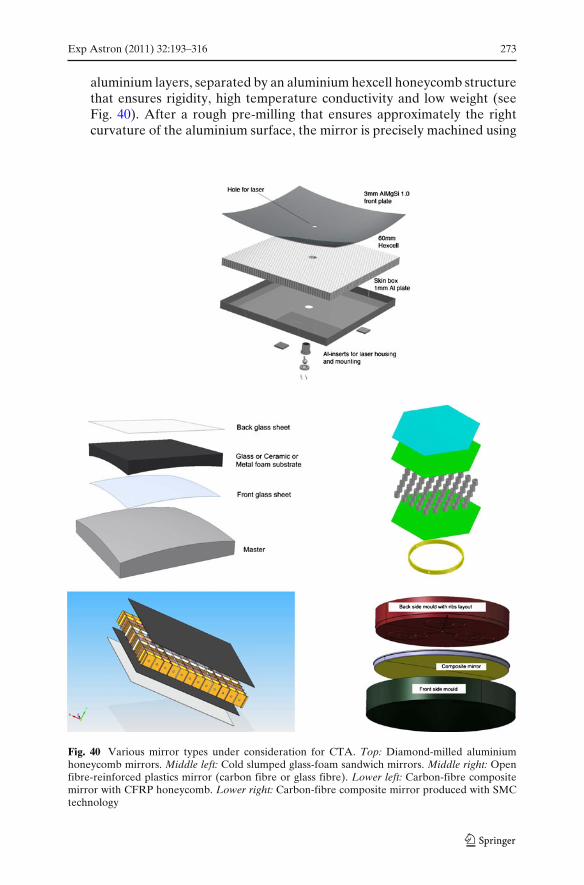
Exp Astron (2011) 32:193–316 273
aluminium layers, separated by an aluminium hexcell honeycomb structurethat ensures rigidity, high temperature conductivity and low weight (seeFig. 40). After a rough pre-milling that ensures approximately the rightcurvature of the aluminium surface, the mirror is precisely machined using
Fig. 40 Various mirror types under consideration for CTA. Top: Diamond-milled aluminiumhoneycomb mirrors. Middle left: Cold slumped glass-foam sandwich mirrors. Middle right: Openfibre-reinforced plastics mirror (carbon fibre or glass fibre). Lower left: Carbon-fibre compositemirror with CFRP honeycomb. Lower right: Carbon-fibre composite mirror produced with SMCtechnology

274 Exp Astron (2011) 32:193–316
diamond-milling techniques. A thin layer of quartz of ∼ 100 nm thickness,with some carbon admixture, is plasma coated on the mirror surface forprotection against corrosion. Diamond-milled mirrors have proven moreresistant to ageing effects (reflectance loss of 1–2% per year) than mirrorswith a thin reflective coatings on glass or other substrates, presumablysince the reflective layer cannot be locally destroyed. On the other hand,the initial reflectance of diamond-milled mirrors is a few percent lower.
An ongoing development is the mass production of mirror panels by meansof replication technologies. These are cost effective and can be used to pro-duce non-spherical and very light-weight mirrors with good and reproducibleoptical quality. Replication methods look to be promising for the large-scaleproduction of CTA mirror facets and will be considered as the baselinedesign, although long-term tests are still required. Replica production methodsinclude:
Cold slumped glass mirrors. The mirror panels are composed of two thin glasssheets (1–2 mm) glued as to a suitable core material, giving a structurewith the necessary rigidity. Construction proceeds as follows: At roomtemperature, the front glass sheet is formed to the required optical shapeon a master by means of vacuum suction. The core material and thesecond glass sheet are glued to it. After the curing of the glue, the panel isreleased from the master, sealed and coated in the same way as a glassmirror. Half of the mirrors of the MAGIC II telescope were producedwith this technology using an aluminium honeycomb Hexcell structure ascore material [104]. For CTA, other core materials are under investigation,such as various foams. Especially promising is an all-glass closed-cell foamthat can be pre-machined to the required curvature (see Fig. 40). Furtherinvestigation of the effects of thermal insulation between the front and theback of the mirror caused by foams is required.
Aluminium foil mirrors. Aluminium honeycomb sandwich mirrors withreflective aluminium sheets of 1–2 mm thickness (made e.g. by the com-pany Alanod) are also being studied in detail. Their main limitationcurrently results from the imperfect reflection properties of the aluminiumfoil.
Fibre reinforced plastics mirrors. Several attempts are being made to usecarbon- or glass-fibre reinforced plastic materials to produce light-weightmirror facets. Three different technologies are currently under develop-ment for CTA: (a) an open sandwich structure of glass-fibre or carbon-fibre reinforced plastic, consisting of two flat plates and spacers with eitheran epoxy layer cast on one plate or a bent thin glass sheet glued to it to formthe mirror surface; (b) a closed structure of two carbon-fibre reinforcedplastic plates bent to the required radius of curvature, an intermediatepre-machined CFRP honeycomb for stability and a thin glass sheet asreflecting surface; and (c) a one-piece design using a compound containingcarbon-fibre and the high-temperature and high-pressure sheet moulding(SMC) technology, which is frequently used in the automotive industry.
Exp Astron (2011) 32:193–316 275
To form a smooth surface in the same production step an in-mould coatingtechnology is under investigation which would allow for production timesof the order of just a few minutes per substrate. See Fig. 40 for the differentmirror types.
Since the mirrors are permanently exposed to the environment, degradationof mirror reflectivity is a serious concern. In the case of aluminium-coatedmirrors, water can creep along the interface of the glass and aluminium layerbecause the aluminium does not stick perfectly to the glass surface and the pro-tective layers often have pin holes. In contrast, solid aluminium mirrors showlocalised corrosion, which, even when deep, affects only a very small fractionof the surface. Possible cures for the glass mirrors could be intermediate layersimproving adhesion, e.g. of chromium or SiO, or more resistant protectionlayers, for example multiple layers which reduce the probability of pin holesin the coating. Multi-layer protective coatings could also be used to enhancereflectivity in the relevant wavelength region. These are under investigation asare purely dielectric coatings without any aluminium, which consist of multiplelayers with different refractive indices. These latter can in principle providereflectances of up to 98% and would not suffer from the rather weak adhesionof aluminium to glass.
Another option to improve the mirror lifetime is to apply the reflectivecoating to the protected back side of a thin glass sheet, which could thenbe used in the replication techniques described above. Disadvantages aretransmission losses in the glass, the requirement of a very uniform glassthickness, as the mould defines the shape of the front side but the reflectivelayer is on the back, and, in addition, icing problems due to radiation coolingof the front surface.
In summary, many different technologies for the production of mirrorfacets are under investigation. For several of them, large-scale productionexperience exists already, others are in a development phase. A challenge inmirror production will be to find the optimum compromise between mirrorlifetime and production costs. Current production costs are 1,650 e/m2 forthe 0.7 m2 H.E.S.S. II glass mirrors, 2,450 e/m2 for the 1.0 m2 MAGIC IImilled-aluminium mirrors, and 2,000 e/m2 for the 1.0 m2 MAGIC II cold-slumped glass mirrors. The much larger production scale of CTA and the useof optimised techniques is expected to result in a significant reduction in cost,in particular for the replication technologies. Current baseline specificationsfor MST mirror facets are summarised in Table 2.
Table 2 Baselinespecifications for mirrorfacets (MST)
Shape HexagonalSize 1,200 mm flat-to-flatType Spherical (aspherical opt.)Focal length ∼16 mReflectance >80% between 300 and 600 nmSpot size <1 mrad diameter (80% containment)
276 Exp Astron (2011) 32:193–316
9.2.3 Mirror support and alignment
To achieve design performance, mirror facets need to be aligned with aprecision which is about an order of magnitude better than the optical pointspread function, i.e. given the PSF requirement of <1 mrad the alignmentprecision needs to be well below 0.1 mrad or 100 μm (assuming a typical 1 mlever arm between mirror support points). Various alignment methods are inuse for existing telescopes:
Manual alignment. Using an appropriate adjustment mechanism, mirror facetsare manually aligned after mounting. For technical reasons, alignment isusually performed at or near the stow position of the telescope. Deforma-tions in dish shape between the stow position and the average observationposition (at 60–70◦ elevation) can be compensated by “misaligning” mir-rors by the appropriate amount in the stow position. This scheme is usedin the VERITAS telescopes [105].
Actuator-based alignment. Initial alignment of mirrors is carried out byremote-controlled actuators, using the image of a star viewed on thecamera lid by a CCD camera on the dish, and implementing a feedbackloop which moves all facet spots to a common location. This scheme isemployed by H.E.S.S. [83].
Active alignment. Remote-controlled actuators are used not only for initialalignment of facets, but also to compensate for deformations of the dish,in particular as a function of elevation. If dish deformations are elastic,reproducible and not very large compared to the point spread function,alignment corrections can be based on a lookup table of actuator positionsas a function of telescope pointing. If deformations are large or inelastic,a closed feedback loop can be implemented by actively monitoring facetpointing, using lasers attached to each facet and imaged onto a target inthe focal plane. Active alignment is used by MAGIC [102].
Technically, the requirements for the actuator-based alignment and theactive alignment are very similar, the main difference being that for ac-tive alignment of a significant fraction of facets need to be moved simul-taneously or nearly simultaneously as telescope pointing changes, requir-ing parallel rather than serial control of actuators and a higher-capacitypower supply. Since manual alignment of the large number of CTA mirrorfacets is impractical, certainly the medium-sized and large telescopes will beequipped with actuators. The small and medium sized telescopes will havemechanically stable dish structures which do not necessarily require activecontrol, but active (look-up table driven) mirror control could be imple-mented to maintain optimum point spread function over the entire elevationrange.
Desirable features for actuators include a movement range of at least 30 mmand a built-in relative or, better, absolute position encoder which allows theactuator to be moved by an exact pre-defined amount. This is particularlyrelevant for lookup-based corrections. For active alignment, the positioning
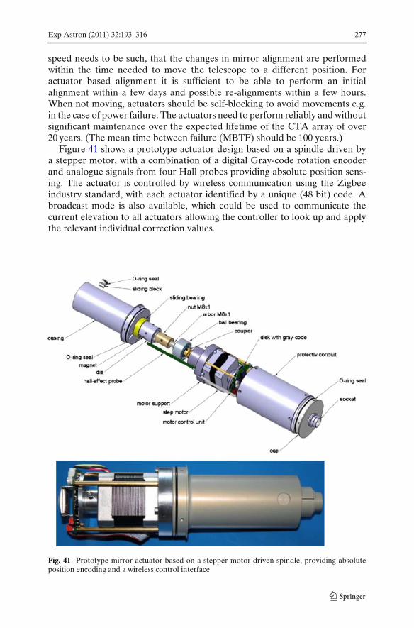
Exp Astron (2011) 32:193–316 277
speed needs to be such, that the changes in mirror alignment are performedwithin the time needed to move the telescope to a different position. Foractuator based alignment it is sufficient to be able to perform an initialalignment within a few days and possible re-alignments within a few hours.When not moving, actuators should be self-blocking to avoid movements e.g.in the case of power failure. The actuators need to perform reliably and withoutsignificant maintenance over the expected lifetime of the CTA array of over20 years. (The mean time between failure (MBTF) should be 100 years.)
Figure 41 shows a prototype actuator design based on a spindle driven bya stepper motor, with a combination of a digital Gray-code rotation encoderand analogue signals from four Hall probes providing absolute position sens-ing. The actuator is controlled by wireless communication using the Zigbeeindustry standard, with each actuator identified by a unique (48 bit) code. Abroadcast mode is also available, which could be used to communicate thecurrent elevation to all actuators allowing the controller to look up and applythe relevant individual correction values.
Fig. 41 Prototype mirror actuator based on a stepper-motor driven spindle, providing absoluteposition encoding and a wireless control interface
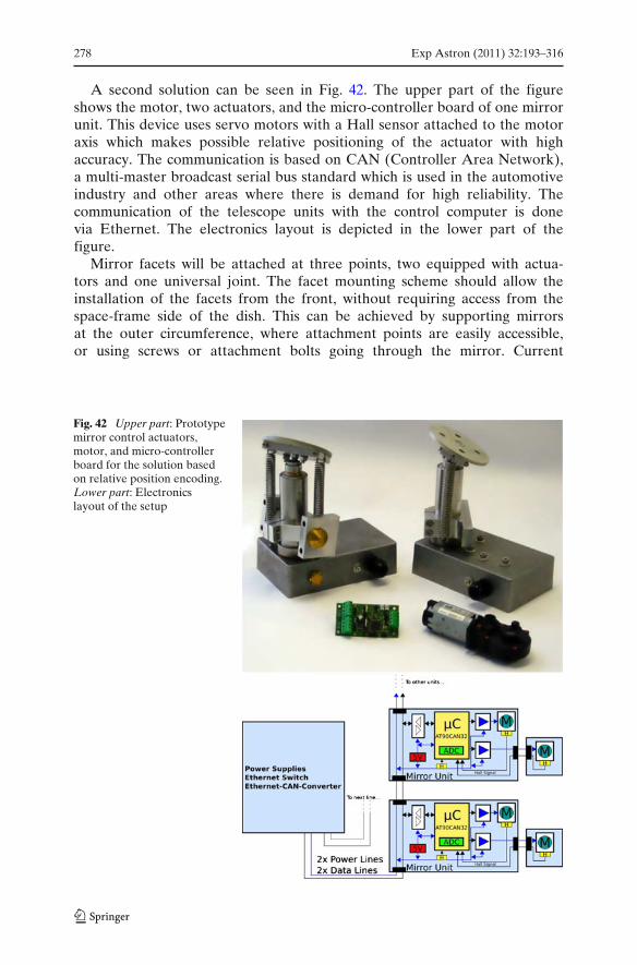
278 Exp Astron (2011) 32:193–316
A second solution can be seen in Fig. 42. The upper part of the figureshows the motor, two actuators, and the micro-controller board of one mirrorunit. This device uses servo motors with a Hall sensor attached to the motoraxis which makes possible relative positioning of the actuator with highaccuracy. The communication is based on CAN (Controller Area Network),a multi-master broadcast serial bus standard which is used in the automotiveindustry and other areas where there is demand for high reliability. Thecommunication of the telescope units with the control computer is donevia Ethernet. The electronics layout is depicted in the lower part of thefigure.
Mirror facets will be attached at three points, two equipped with actua-tors and one universal joint. The facet mounting scheme should allow theinstallation of the facets from the front, without requiring access from thespace-frame side of the dish. This can be achieved by supporting mirrorsat the outer circumference, where attachment points are easily accessible,or using screws or attachment bolts going through the mirror. Current
Fig. 42 Upper part: Prototypemirror control actuators,motor, and micro-controllerboard for the solution basedon relative position encoding.Lower part: Electronicslayout of the setup
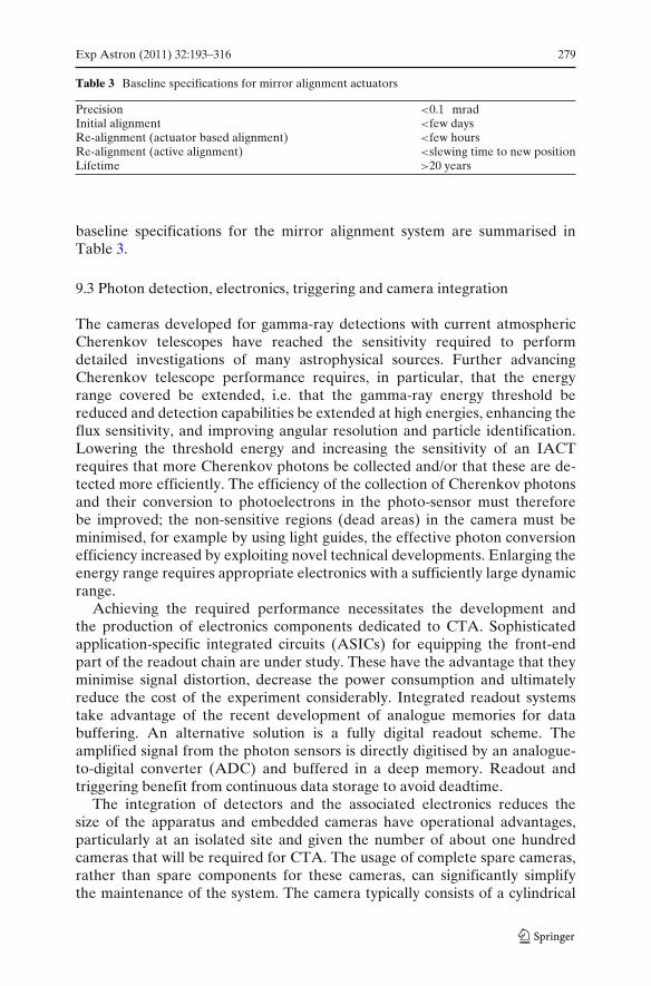
Exp Astron (2011) 32:193–316 279
Table 3 Baseline specifications for mirror alignment actuators
Precision <0.1 mradInitial alignment <few daysRe-alignment (actuator based alignment) <few hoursRe-alignment (active alignment) <slewing time to new positionLifetime >20 years
baseline specifications for the mirror alignment system are summarised inTable 3.
9.3 Photon detection, electronics, triggering and camera integration
The cameras developed for gamma-ray detections with current atmosphericCherenkov telescopes have reached the sensitivity required to performdetailed investigations of many astrophysical sources. Further advancingCherenkov telescope performance requires, in particular, that the energyrange covered be extended, i.e. that the gamma-ray energy threshold bereduced and detection capabilities be extended at high energies, enhancing theflux sensitivity, and improving angular resolution and particle identification.Lowering the threshold energy and increasing the sensitivity of an IACTrequires that more Cherenkov photons be collected and/or that these are de-tected more efficiently. The efficiency of the collection of Cherenkov photonsand their conversion to photoelectrons in the photo-sensor must thereforebe improved; the non-sensitive regions (dead areas) in the camera must beminimised, for example by using light guides, the effective photon conversionefficiency increased by exploiting novel technical developments. Enlarging theenergy range requires appropriate electronics with a sufficiently large dynamicrange.
Achieving the required performance necessitates the development andthe production of electronics components dedicated to CTA. Sophisticatedapplication-specific integrated circuits (ASICs) for equipping the front-endpart of the readout chain are under study. These have the advantage that theyminimise signal distortion, decrease the power consumption and ultimatelyreduce the cost of the experiment considerably. Integrated readout systemstake advantage of the recent development of analogue memories for databuffering. An alternative solution is a fully digital readout scheme. Theamplified signal from the photon sensors is directly digitised by an analogue-to-digital converter (ADC) and buffered in a deep memory. Readout andtriggering benefit from continuous data storage to avoid deadtime.
The integration of detectors and the associated electronics reduces thesize of the apparatus and embedded cameras have operational advantages,particularly at an isolated site and given the number of about one hundredcameras that will be required for CTA. The usage of complete spare cameras,rather than spare components for these cameras, can significantly simplifythe maintenance of the system. The camera typically consists of a cylindrical
280 Exp Astron (2011) 32:193–316
structure built completely from low mass components. It holds a matrix ofphoton sensor cells, carefully optimised to make maximal use of the incominglight, and is fixed to the arms of the telescope in the focal plane, above thedish of the telescope. For embedded cameras, the light sensor, readout andtrigger system, data acquisition system and power supply are integrated in amodular mechanical structure. The only connections that enter the camera arethe input power, the communication network, and any central trigger cables.Disadvantages are a heavy camera requiring considerable cooling power and aheavy camera support structure.
9.3.1 Photon detection
The photon sensors most commonly used in IACTs are photomultipliers withalkali photo cathodes and electron multipliers based on a chain of dynodes.The technology is well-established, but is subject to continuous developmentand improvement. PMTs have established themselves as the best available lowlight level sensors for ultra-fast processes. The relatively high peak quantumefficiency (QE) currently available (up to 30%), together with high gainsof up to 106 and low noise, allow the reliable measurement even of singlephotoelectrons. A dynamic range of about 5,000 photoelectrons is obtainablewith PMTs. The PMTs convert impinging photons into a charge pulse of sizemeasured in number of photoelectrons. IACTs usually use PMTs with bialkalitype photo-cathodes, as these provide the highest QE. They are sensitive in thewavelength range of 300–600 nm (200–600 nm if a PMT with a quartz windowis used). The bialkali PMT sensitivity curve is well-matched to the spectrum ofCherenkov light arriving at ground level from air showers. As a rule, one needsto amplify this pulse in order to match the sensitivity of the data acquisition(DAQ) electronics. However, new photon detectors are under study and theCTA cameras must be designed to allow their integration if their performanceand cost provide significant advantages over PMTs.
Criteria for photo-detectors
Spectral sensitivity The spectrum of Cherenkov light is cut off below 300 nm,due to atmospheric transmission effects, and falls off as 1/λ2 towardslonger wavelengths.5 Candidate photo-detectors should be matched to thepeak in this spectrum at around 350 nm. At large wavelengths, beyondabout 550 nm, the signal-to-noise ratio becomes increasingly unfavourabledue of the increasing intensity of the night sky background in this region.Above ∼650 nm strong emission lines are present in the Cherenkovspectrum, originating from the rotational levels of (OH) groups. It istherefore desirable but not essential to measure up to wavelengths of about
5Due to Rayleigh and Mie scattering the actual spectrum at the camera is considerably flatter (seeFig. 43). At large zenith angles the UV part of the spectrum might no longer be detectable.
Exp Astron (2011) 32:193–316 281
600–650 nm. (The more accurately the absolute charge in an image ismeasured, the better the absolute calibration.)
Sensor area Currently favoured pixel sizes are around 0.1◦ for the LST,0.18◦ for the MST, and 0.25◦ for the SST. For conventional telescopedesigns (single mirror optics, with Davies–Cotton or parabolic reflectors),these angular sizes translate to linear dimensions of 40, 50 and 35 mm,respectively. If a secondary-optics design is used for the SST, a size of 0.2◦represents around 6 mm. For the secondary-optics design for the MST, asmaller angular pixel size of 0.07◦ equates to the same physical size of6 mm. Light-collecting Winston cones in front of any sensor reduce therequired sensor size by a factor of 3–4 compared to the pixel size and candecrease the amount of dead space between pixels.
Sensor uniformity Sensor non-uniformities below ∼10% are tolerable. Largernon-uniformities should be avoided as they introduce an additional vari-able component in the light collection and thus increase the variance ofthe output signal.
Dynamic range and linearity Sensors should be able to detect single photonsand provide a dynamic range of up to 5,000 photo-electrons, with linearitydeviations below a few per cent. Non-linearities can be tolerated if theycan be accurately corrected for in the calibration procedure.
Temporal response The time dispersion of Cherenkov photons across a cameraimage depends on the energy of the primary gamma ray. At low energies,the dispersion is only few nanoseconds. Matched short signal integrationwindows are used to minimise the noise. The photo-sensor must notsignificantly lengthen the time structure of a Cherenkov light pulse. Itis desirable to determine the pulse arrival times with sub-nanosecondprecision for sufficiently large light pulses.
Lifetime Sensors will detect photons from the night-sky background at a typicalrate of about 100–200 MHz for the telescopes with large collection areas(MST and LST). If operation is attempted when the moon is up, this ratecan increase by an order of magnitude. Sensors should have a lifetime of10 years for an annual exposure of up to ∼2,000 h. This can be achievedusing PMTs with only 6–8 dynodes, operated at a gain of 30,000–50,000,followed by a fast AC-coupled preamplifier.
Rate of spurious signals Spurious signals from photo-detectors can result inan increase of trigger rates and a degradation of trigger thresholds. Thisis a particular issue for photomultiplier sensors where residual gas atomsin the tubes are ionised by impinging electrons. The resulting afterpulses,produced by positively charged heavy ions bombarding the photo-cathode,may have large amplitude and long delays relative to the primary electron.Photomultipliers should be selected with an afterpulse probability below(∼10−4–10−5).
Operational characteristics To ensure efficient and reliable operation of thesystems, sensors should show good short- and medium-term stability,and only gradual ageing, if any. Sensors should be able to survive highillumination levels.
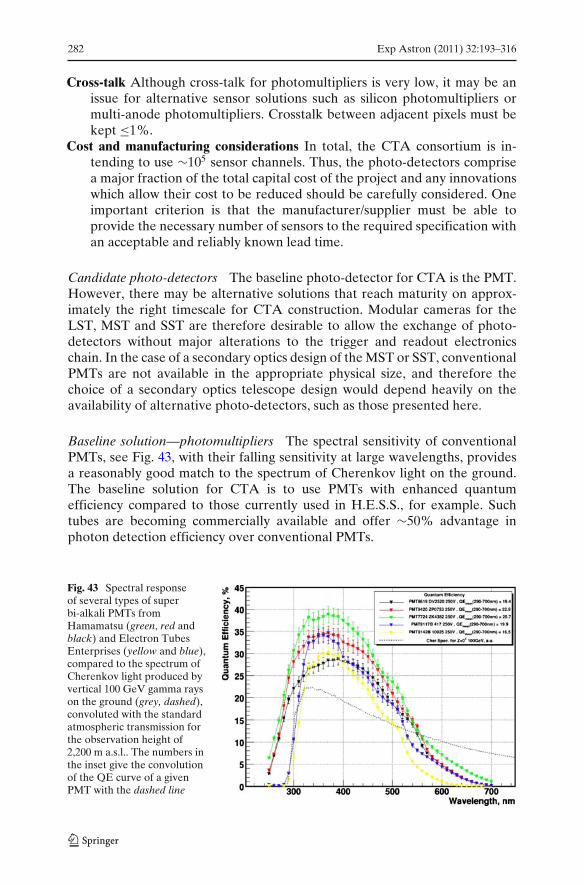
282 Exp Astron (2011) 32:193–316
Cross-talk Although cross-talk for photomultipliers is very low, it may be anissue for alternative sensor solutions such as silicon photomultipliers ormulti-anode photomultipliers. Crosstalk between adjacent pixels must bekept ≤1%.
Cost and manufacturing considerations In total, the CTA consortium is in-tending to use ∼105 sensor channels. Thus, the photo-detectors comprisea major fraction of the total capital cost of the project and any innovationswhich allow their cost to be reduced should be carefully considered. Oneimportant criterion is that the manufacturer/supplier must be able toprovide the necessary number of sensors to the required specification withan acceptable and reliably known lead time.
Candidate photo-detectors The baseline photo-detector for CTA is the PMT.However, there may be alternative solutions that reach maturity on approx-imately the right timescale for CTA construction. Modular cameras for theLST, MST and SST are therefore desirable to allow the exchange of photo-detectors without major alterations to the trigger and readout electronicschain. In the case of a secondary optics design of the MST or SST, conventionalPMTs are not available in the appropriate physical size, and therefore thechoice of a secondary optics telescope design would depend heavily on theavailability of alternative photo-detectors, such as those presented here.
Baseline solution—photomultipliers The spectral sensitivity of conventionalPMTs, see Fig. 43, with their falling sensitivity at large wavelengths, providesa reasonably good match to the spectrum of Cherenkov light on the ground.The baseline solution for CTA is to use PMTs with enhanced quantumefficiency compared to those currently used in H.E.S.S., for example. Suchtubes are becoming commercially available and offer ∼50% advantage inphoton detection efficiency over conventional PMTs.
Fig. 43 Spectral responseof several types of superbi-alkali PMTs fromHamamatsu (green, red andblack) and Electron TubesEnterprises (yellow and blue),compared to the spectrum ofCherenkov light produced byvertical 100 GeV gamma rayson the ground (grey, dashed),convoluted with the standardatmospheric transmission forthe observation height of2,200 m a.s.l.. The numbers inthe inset give the convolutionof the QE curve of a givenPMT with the dashed line
Exp Astron (2011) 32:193–316 283
Silicon photomultipliers (SiPMs) (known also as MPPCs, GAPDs and Micro-channel APDs) are novel light sensors that are rapidly reaching maturity. Themore recent SiPMs consist of single pixels which contain several hundred tothousands cells, coupled to a single output, Each cell is operated in Geigermode. An arriving photon can trigger the cell, after which that cells sufferssignificant deadtime, but leaves the surrounding cells ready to collect otherarriving photons. The photon-counting dynamic range is comparable to thenumber of cells. Silicon photo-sensors could provide higher photon detectionefficiencies than the latest PMTs at lower cost and without the requirement forhigh-voltage. However, silicon sensors typically require cooling to reduce thedark count to a manageable level and also suffer from optical cross-talk and arenot as well matched to the Cherenkov light spectrum as PMTs. They thereforerequire further improvement and commercialisation. However, depending onthe time scale and cost of such a development, SiPMs could be considered as acandidate sensor for replacing the PMTs or, alternatively, as an upgrade pathfor all telescope sizes. They are of particular interest for the SST secondaryoptics option, where their physical size is better suited to the plate scale of thetelescope.
Multi-anode photomultipliers MAPMTs provide multiple pixels in a compactpackage, with properties similar to monolithic PMTs. Such devices offerindividual pixel sizes of the order of 6 mm, suitable for secondary opticsschemes. Enhanced quantum efficiency versions with up to 64 channels arenow available. The suitability of MAPMTs must be assessed, and propertiessuch as the uniformity, cross-talk, dynamic range and detection efficiency arecurrently under investigation.
Associated systems
Light-collecting Winston cones Winston cones placed in front of any sensorcould reduce the required sensor size by a factor of 3–4 (see Fig. 44). However,compression is limited by Liouville’s theorem, which states that the phase-space volume of an ensemble of photons is conserved. Lightcones can minimisethe dead space between pixels and reduce the amount of stray light fromthe night sky impinging on the sensors at large incidence angles. Figure 44illustrates the typical angular response of a light funnel. Current lightconeshave a net transmission of about 80%. Improved cones may allow increasedperformance at modest cost.
Plexiglas input window To avoid the deposition of dust on the photo-detectors and lightcones (if used), a Plexiglas window could be utilised to sealthe camera. The transmission losses of ∼8% for a 3 mm thick GS 2458 windowmay be considered as well-justified because of the absence of deteriorationof the light throughput on long time scales. The use of a sealed camera andplexiglas window must be investigated for each telescope size. For the LSTsand MSTs, sealing the camera does not significantly increase its total cost. For
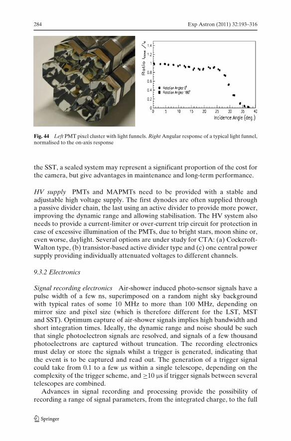
284 Exp Astron (2011) 32:193–316
Fig. 44 Left PMT pixel cluster with light funnels. Right Angular response of a typical light funnel,normalised to the on-axis response
the SST, a sealed system may represent a significant proportion of the cost forthe camera, but give advantages in maintenance and long-term performance.
HV supply PMTs and MAPMTs need to be provided with a stable andadjustable high voltage supply. The first dynodes are often supplied througha passive divider chain, the last using an active divider to provide more power,improving the dynamic range and allowing stabilisation. The HV system alsoneeds to provide a current-limiter or over-current trip circuit for protection incase of excessive illumination of the PMTs, due to bright stars, moon shine or,even worse, daylight. Several options are under study for CTA: (a) Cockcroft-Walton type, (b) transistor-based active divider type and (c) one central powersupply providing individually attenuated voltages to different channels.
9.3.2 Electronics
Signal recording electronics Air-shower induced photo-sensor signals have apulse width of a few ns, superimposed on a random night sky backgroundwith typical rates of some 10 MHz to more than 100 MHz, depending onmirror size and pixel size (which is therefore different for the LST, MSTand SST). Optimum capture of air-shower signals implies high bandwidth andshort integration times. Ideally, the dynamic range and noise should be suchthat single photoelectron signals are resolved, and signals of a few thousandphotoelectrons are captured without truncation. The recording electronicsmust delay or store the signals whilst a trigger is generated, indicating thatthe event is to be captured and read out. The generation of a trigger signalcould take from 0.1 to a few μs within a single telescope, depending on thecomplexity of the trigger scheme, and ≥10 μs if trigger signals between severaltelescopes are combined.
Advances in signal recording and processing provide the possibility ofrecording a range of signal parameters, from the integrated charge, to the full
Exp Astron (2011) 32:193–316 285
pulse shape over a fixed time window. Whilst it is not yet clear that the fullpulse shape is needed, it is desirable to record at least a few parameters of thepulse shape rather than just the integrated charge. In this way, absolute timinginformation would be available, allowing improved background rejection andadaptive integration windows. Increasing the bandwidth of the signal recordingsystem will allow improved timing and shorter integration gates, resultingin reduced levels of night sky background under the signal. However, asthe bandwidth of the system is increased, so is the cost. Whilst such anapproach may be justified for the LST, where night sky background is high,the Cherenkov pulses are very fast and the number of telescopes is low, thisis not necessarily the case for the SST, where the night sky background islow, the Cherenkov pulses are not as fast and any cost savings could be usedto build more telescopes. The bandwidth of the electronics chain for a giventelescope size should be motivated by examining its consequences for the arraysensitivity and energy threshold through Monte Carlo simulations. Currently,there is no clear answer as to the optimum choice for any telescope size, and thesignal sampling frequencies under discussion range from a few 100 MSample/sto ∼2 GSample/s.
Two techniques for signal recording and processing are in use in existingIACT arrays, These are based around Flash Analogue-to-Digital Converters(FADCs) and analogue sampling memories, and form the basis for the CTAdevelopment:
Flash analogue-to-digital converters FADCs digitise the photon-sensor sig-nals at rates of a few 100 MSample/s to a few GSample/s, writing the outputinto a digital ring buffer, often realised as a very large scale integration gatearray which also provides control logic and digital readout. The modest cost ofdigital buffers allows large trigger latency; delays of tens of microseconds canbe realised. However, the dynamic range of FADCs is limited and typicallyno more than 8–10 bits are available, requiring either parallel conversion withdifferent gains or dynamic gain switching, as used in the 500 MSample/s, 8-bitVERITAS FADC system [106]. The rather high cost of the fastest FADCshas led to the development of systems in which several channels are time-multiplexed onto one ADC, as used in the MAGIC 2 GSample/s, 10-bit FADCsystem. In principle, FADC based recording systems allow the use of a purelydigital trigger, acting on the digitised data in the ring buffer, to select air showerevents. Such a system is sketched in Fig. 45. None of the systems implementedso far uses this approach. Instead, parallel analogue trigger circuitry is used,adding not insignificant complexity to the electronics layout. The steadilyincreasing power of VLSI gate arrays may soon make digital trigger processorsan attractive and feasible option.
As well as being expensive, FADCs suitable for IACTs are traditionally alsobulky and power hungry, negating the possibility of integrating the readoutelectronics into the camera and requiring the transmission of analogue signalsover many tens of meters to a counting house. However, the recent devel-opment of low-power, low-cost FADCs in recent years imply this situation
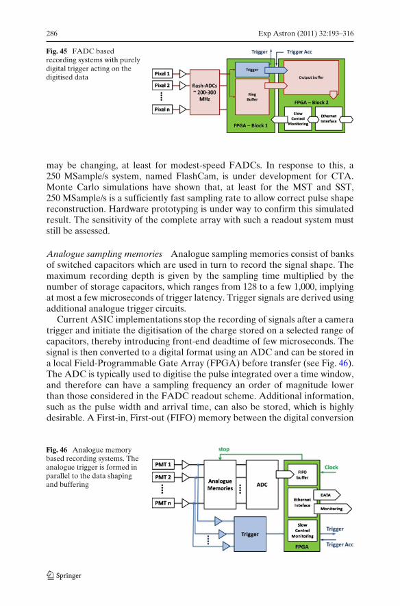
286 Exp Astron (2011) 32:193–316
Fig. 45 FADC basedrecording systems with purelydigital trigger acting on thedigitised data
may be changing, at least for modest-speed FADCs. In response to this, a250 MSample/s system, named FlashCam, is under development for CTA.Monte Carlo simulations have shown that, at least for the MST and SST,250 MSample/s is a sufficiently fast sampling rate to allow correct pulse shapereconstruction. Hardware prototyping is under way to confirm this simulatedresult. The sensitivity of the complete array with such a readout system muststill be assessed.
Analogue sampling memories Analogue sampling memories consist of banksof switched capacitors which are used in turn to record the signal shape. Themaximum recording depth is given by the sampling time multiplied by thenumber of storage capacitors, which ranges from 128 to a few 1,000, implyingat most a few microseconds of trigger latency. Trigger signals are derived usingadditional analogue trigger circuits.
Current ASIC implementations stop the recording of signals after a cameratrigger and initiate the digitisation of the charge stored on a selected range ofcapacitors, thereby introducing front-end deadtime of few microseconds. Thesignal is then converted to a digital format using an ADC and can be stored ina local Field-Programmable Gate Array (FPGA) before transfer (see Fig. 46).The ADC is typically used to digitise the pulse integrated over a time window,and therefore can have a sampling frequency an order of magnitude lowerthan those considered in the FADC readout scheme. Additional information,such as the pulse width and arrival time, can also be stored, which is highlydesirable. A First-in, First-out (FIFO) memory between the digital conversion
Fig. 46 Analogue memorybased recording systems. Theanalogue trigger is formed inparallel to the data shapingand buffering
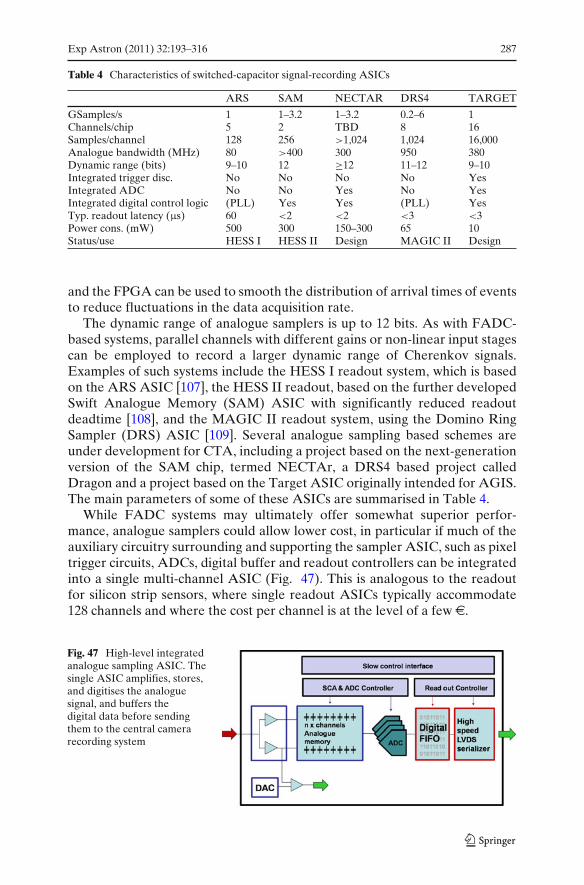
Exp Astron (2011) 32:193–316 287
Table 4 Characteristics of switched-capacitor signal-recording ASICs
ARS SAM NECTAR DRS4 TARGET
GSamples/s 1 1–3.2 1–3.2 0.2–6 1Channels/chip 5 2 TBD 8 16Samples/channel 128 256 >1,024 1,024 16,000Analogue bandwidth (MHz) 80 >400 300 950 380Dynamic range (bits) 9–10 12 ≥12 11–12 9–10Integrated trigger disc. No No No No YesIntegrated ADC No No Yes No YesIntegrated digital control logic (PLL) Yes Yes (PLL) YesTyp. readout latency (μs) 60 <2 <2 <3 <3Power cons. (mW) 500 300 150–300 65 10Status/use HESS I HESS II Design MAGIC II Design
and the FPGA can be used to smooth the distribution of arrival times of eventsto reduce fluctuations in the data acquisition rate.
The dynamic range of analogue samplers is up to 12 bits. As with FADC-based systems, parallel channels with different gains or non-linear input stagescan be employed to record a larger dynamic range of Cherenkov signals.Examples of such systems include the HESS I readout system, which is basedon the ARS ASIC [107], the HESS II readout, based on the further developedSwift Analogue Memory (SAM) ASIC with significantly reduced readoutdeadtime [108], and the MAGIC II readout system, using the Domino RingSampler (DRS) ASIC [109]. Several analogue sampling based schemes areunder development for CTA, including a project based on the next-generationversion of the SAM chip, termed NECTAr, a DRS4 based project calledDragon and a project based on the Target ASIC originally intended for AGIS.The main parameters of some of these ASICs are summarised in Table 4.
While FADC systems may ultimately offer somewhat superior perfor-mance, analogue samplers could allow lower cost, in particular if much of theauxiliary circuitry surrounding and supporting the sampler ASIC, such as pixeltrigger circuits, ADCs, digital buffer and readout controllers can be integratedinto a single multi-channel ASIC (Fig. 47). This is analogous to the readoutfor silicon strip sensors, where single readout ASICs typically accommodate128 channels and where the cost per channel is at the level of a few e.
Fig. 47 High-level integratedanalogue sampling ASIC. Thesingle ASIC amplifies, stores,and digitises the analoguesignal, and buffers thedigital data before sendingthem to the central camerarecording system
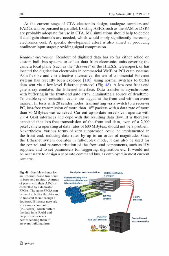
288 Exp Astron (2011) 32:193–316
At the current stage of CTA electronics design, analogue samplers andFADCs will be pursued in parallel. Existing ASICs such as the SAM or DSR4are probably adequate for use in CTA. MC simulations should help to decideif dual-gain channels are needed, which would imply significantly increasingelectronics cost. A specific development effort is also aimed at producingnonlinear input stages providing signal compression.
Readout electronics Readout of digitised data has so far either relied oncustom-built bus systems to collect data from electronics units covering thecamera focal plane (such as the “drawers” of the H.E.S.S. telescopes), or haslocated the digitisation electronics in commercial VME or PCI crate systems.As a flexible and cost-effective alternative, the use of commercial Ethernetsystems has recently been explored [110], using normal switches to bufferdata sent via a low-level Ethernet protocol (Fig. 48). A low-cost front-endgate array emulates the Ethernet interface. Data transfer is asynchronous,with buffering in the front-end gate array, eliminating a source of deadtime.To enable synchronisation, events are tagged at the front end with an eventmarker. In tests with 20 sender nodes, transmitting via a switch to a receiverPC, loss-free transmission of more than 1010 packets with a data rate of morethan 80 MByte/s was achieved. Current up-to-date servers can operate with2 × 4 GBit interfaces and cope with the resulting data flow. It is thereforeexpected that loss-free transmission of the front-end data, even of a 2,000pixel camera operating at data rates of 600 MByte/s, should not be a problem.Nevertheless, various forms of zero suppression could be implemented inthe front end, reducing data rates by up to an order of magnitude. Sincethe Ethernet system operates in full-duplex mode, it can also be used forthe control and parameterisation of the front-end components, such as HVsupplies, and to set parameters for triggering, digitisation etc. It would notbe necessary to design a separate command bus, as employed in most currentcameras.
Fig. 48 Possible scheme foran Ethernet-based front-endto back-end readout. A groupof pixels with their ADCs iscontrolled by a dedicatedFPGA. The same FPGA canbe used to buffer the data andto transmit them through adedicated Ethernet networkto a camera computer(PC Server), which buffersthe data in its RAM andpreprocesses eventsbefore sending them toan event building farm
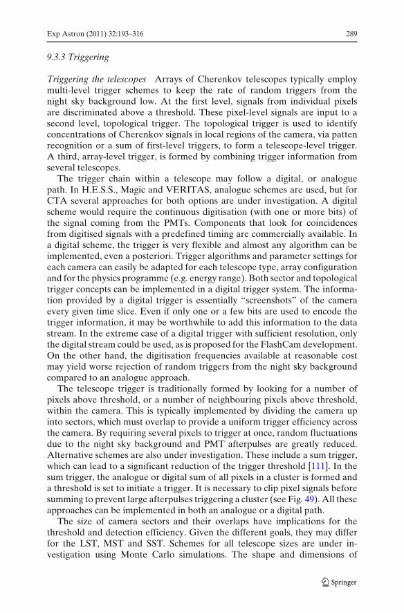
Exp Astron (2011) 32:193–316 289
9.3.3 Triggering
Triggering the telescopes Arrays of Cherenkov telescopes typically employmulti-level trigger schemes to keep the rate of random triggers from thenight sky background low. At the first level, signals from individual pixelsare discriminated above a threshold. These pixel-level signals are input to asecond level, topological trigger. The topological trigger is used to identifyconcentrations of Cherenkov signals in local regions of the camera, via pattenrecognition or a sum of first-level triggers, to form a telescope-level trigger.A third, array-level trigger, is formed by combining trigger information fromseveral telescopes.
The trigger chain within a telescope may follow a digital, or analoguepath. In H.E.S.S., Magic and VERITAS, analogue schemes are used, but forCTA several approaches for both options are under investigation. A digitalscheme would require the continuous digitisation (with one or more bits) ofthe signal coming from the PMTs. Components that look for coincidencesfrom digitised signals with a predefined timing are commercially available. Ina digital scheme, the trigger is very flexible and almost any algorithm can beimplemented, even a posteriori. Trigger algorithms and parameter settings foreach camera can easily be adapted for each telescope type, array configurationand for the physics programme (e.g. energy range). Both sector and topologicaltrigger concepts can be implemented in a digital trigger system. The informa-tion provided by a digital trigger is essentially “screenshots” of the cameraevery given time slice. Even if only one or a few bits are used to encode thetrigger information, it may be worthwhile to add this information to the datastream. In the extreme case of a digital trigger with sufficient resolution, onlythe digital stream could be used, as is proposed for the FlashCam development.On the other hand, the digitisation frequencies available at reasonable costmay yield worse rejection of random triggers from the night sky backgroundcompared to an analogue approach.
The telescope trigger is traditionally formed by looking for a number ofpixels above threshold, or a number of neighbouring pixels above threshold,within the camera. This is typically implemented by dividing the camera upinto sectors, which must overlap to provide a uniform trigger efficiency acrossthe camera. By requiring several pixels to trigger at once, random fluctuationsdue to the night sky background and PMT afterpulses are greatly reduced.Alternative schemes are also under investigation. These include a sum trigger,which can lead to a significant reduction of the trigger threshold [111]. In thesum trigger, the analogue or digital sum of all pixels in a cluster is formed anda threshold is set to initiate a trigger. It is necessary to clip pixel signals beforesumming to prevent large afterpulses triggering a cluster (see Fig. 49). All theseapproaches can be implemented in both an analogue or a digital path.
The size of camera sectors and their overlaps have implications for thethreshold and detection efficiency. Given the different goals, they may differfor the LST, MST and SST. Schemes for all telescope sizes are under in-vestigation using Monte Carlo simulations. The shape and dimensions of
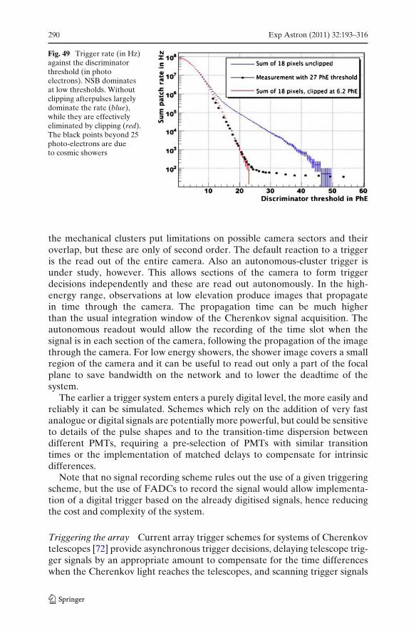
290 Exp Astron (2011) 32:193–316
Fig. 49 Trigger rate (in Hz)against the discriminatorthreshold (in photoelectrons). NSB dominatesat low thresholds. Withoutclipping afterpulses largelydominate the rate (blue),while they are effectivelyeliminated by clipping (red).The black points beyond 25photo-electrons are dueto cosmic showers
the mechanical clusters put limitations on possible camera sectors and theiroverlap, but these are only of second order. The default reaction to a triggeris the read out of the entire camera. Also an autonomous-cluster trigger isunder study, however. This allows sections of the camera to form triggerdecisions independently and these are read out autonomously. In the high-energy range, observations at low elevation produce images that propagatein time through the camera. The propagation time can be much higherthan the usual integration window of the Cherenkov signal acquisition. Theautonomous readout would allow the recording of the time slot when thesignal is in each section of the camera, following the propagation of the imagethrough the camera. For low energy showers, the shower image covers a smallregion of the camera and it can be useful to read out only a part of the focalplane to save bandwidth on the network and to lower the deadtime of thesystem.
The earlier a trigger system enters a purely digital level, the more easily andreliably it can be simulated. Schemes which rely on the addition of very fastanalogue or digital signals are potentially more powerful, but could be sensitiveto details of the pulse shapes and to the transition-time dispersion betweendifferent PMTs, requiring a pre-selection of PMTs with similar transitiontimes or the implementation of matched delays to compensate for intrinsicdifferences.
Note that no signal recording scheme rules out the use of a given triggeringscheme, but the use of FADCs to record the signal would allow implementa-tion of a digital trigger based on the already digitised signals, hence reducingthe cost and complexity of the system.
Triggering the array Current array trigger schemes for systems of Cherenkovtelescopes [72] provide asynchronous trigger decisions, delaying telescope trig-ger signals by an appropriate amount to compensate for the time differenceswhen the Cherenkov light reaches the telescopes, and scanning trigger signals
Exp Astron (2011) 32:193–316 291
for pre-programmed patterns of telescope coincidences. The time to reach atrigger decision and to propagate it back to the telescopes is about 1 μs ormore. While FADC based readout systems can buffer signals for this period,analogue-sampling ASICs will usually not provide sufficient memory depth,and require the halting of waveform sampling after a telescope trigger, whileawaiting a third-level telescope coincidence trigger. The resulting deadtime ofa few μs limits telescope (second-level) trigger rates to some 10 kHz, whichdoes not represent a serious limitation. The latest analogue-sampling ASICsallow digitisation of stored signals on time scales of 2–3 μs (see Table 4),comparable to the array trigger latency. In this case, a new option for thetriggering of the array becomes possible: pixel signals are readout and digitisedafter each telescope trigger, and are stored in digital memory, tagged with anevent number. Given that data are buffered and that buffers can easily be madelarge, restrictions on array trigger latency are greatly relaxed (with GBytememory, about 1 s of data can be buffered) and one can implement a software-based asynchronous trigger. With each local trigger, an absolute timestamp iscaptured for the event with an accuracy of the order of 1 ns and transmittedto the camera CPU. This computer collects the time stamps and possiblyadditional trigger information for each event, e.g. pixel trigger patterns, andtransmits them every 10–100 ms via standard Ethernet using TCP/IP to a ded-icated central trigger computer. The central computer receives all time stampsfrom all telescopes and uses this information to test for time coincidences ofthe events and to derive the telescope system trigger. In addition, the time andtrigger information can be used to obtain a first estimate of the core positionand shower direction. Following the central trigger decision, the central triggerCPU sends the information to the corresponding telescopes about which of thebuffered events are to be rejected and which fulfil the system trigger conditionand should be pre-processed in the camera CPU and transmitted for furtherstereoscopic processing. Assuming a local trigger rate of 10 kHz and that about100 Byte of trigger information are generated from each telescope, the centraltrigger computer needs to handle up to 100 MByte/s in a 100 telescope system,which can be readily be done with today’s technology. In such a trigger scheme,the central trigger decision is software-based, but the “hard” timing from thecamera trigger decision is used. It is therefore scalable, fully flexible and alltypes of sub-systems can be served in parallel. At the same time it uses theshortest possible coincidence gates and provides an optimum suppression ofaccidental coincidences.
9.3.4 Camera integration
Signal transmission from the photo-sensors to the recording electronics rep-resents a critical design issue if the electronics is located far from thephoto-sensors. Conventional cables limit bandwidth, are bulky and difficultto route across telescope bearings, and are costly. MAGIC uses optical signaltransmission, circumventing the first two problems, at considerable expense.H.E.S.S. avoids signal transmission altogether by combining 16 photo-sensors
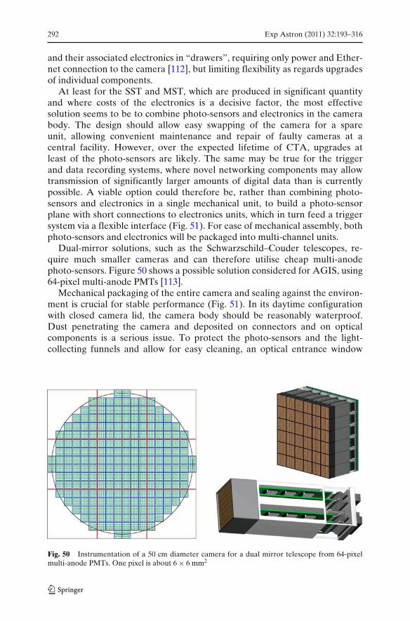
292 Exp Astron (2011) 32:193–316
and their associated electronics in “drawers”, requiring only power and Ether-net connection to the camera [112], but limiting flexibility as regards upgradesof individual components.
At least for the SST and MST, which are produced in significant quantityand where costs of the electronics is a decisive factor, the most effectivesolution seems to be to combine photo-sensors and electronics in the camerabody. The design should allow easy swapping of the camera for a spareunit, allowing convenient maintenance and repair of faulty cameras at acentral facility. However, over the expected lifetime of CTA, upgrades atleast of the photo-sensors are likely. The same may be true for the triggerand data recording systems, where novel networking components may allowtransmission of significantly larger amounts of digital data than is currentlypossible. A viable option could therefore be, rather than combining photo-sensors and electronics in a single mechanical unit, to build a photo-sensorplane with short connections to electronics units, which in turn feed a triggersystem via a flexible interface (Fig. 51). For ease of mechanical assembly, bothphoto-sensors and electronics will be packaged into multi-channel units.
Dual-mirror solutions, such as the Schwarzschild–Couder telescopes, re-quire much smaller cameras and can therefore utilise cheap multi-anodephoto-sensors. Figure 50 shows a possible solution considered for AGIS, using64-pixel multi-anode PMTs [113].
Mechanical packaging of the entire camera and sealing against the environ-ment is crucial for stable performance (Fig. 51). In its daytime configurationwith closed camera lid, the camera body should be reasonably waterproof.Dust penetrating the camera and deposited on connectors and on opticalcomponents is a serious issue. To protect the photo-sensors and the light-collecting funnels and allow for easy cleaning, an optical entrance window
Fig. 50 Instrumentation of a 50 cm diameter camera for a dual mirror telescope from 64-pixelmulti-anode PMTs. One pixel is about 6 × 6 mm2

Exp Astron (2011) 32:193–316 293
Fig. 51 Concept forpackaging of the electroniccontained in the camera
made of near-UV transparent material is desirable, even if this induces amodest light loss due to reflection. While larger-scale integration shouldreduce power consumption compared to current systems, a camera will never-theless consume kilowatts of power and must be cooled. Air cooling requireshigh-quality filtering of the airflow into the camera. Closed-circuit coolingsystems, involving internal circulation of a cooling medium and appropriateheat exchangers improve long-term reliability, but add cost and weight.
9.4 Calibration and atmospheric monitoring
The higher sensitivity of CTA means good gamma-ray statistics for manysources. Therefore, the instrument’s systematic uncertainties may limit theaccuracy of the measurements. The atmosphere is an integral part of anIACT and so monitoring and correcting for atmospheric inhomogeneity mustbe addressed in addition to the detailed calibration and monitoring of theresponse and characteristics of the telescopes. Work is ongoing to address bothissues, as well as their interplay, with the goal of characterising the systematicuncertainties to an unprecedented level.
Already teams of world-experts have gathered to develop state-of-the-artinstrumentation for atmospheric monitoring and the associated science forCTA. These teams are actively participating in the corresponding CTA workpackage (ATAC).
9.4.1 Telescope calibration
The calibration of the CTA telescopes has two distinct aspects. Firstly, the ab-solute gain of the system must be determined. Secondly, the pointing accuracyof the telescope must be measured. The necessity of the precise measurementof the gain of each electronic channel for CTA requires the developmentof a single and reliable calibration device which can measure the flatfieldingcoefficients and the ratio between a single photoelectron and the number ofdigital counts recorded. This development will add to existing experience inbuilding calibration devices, for example the H.E.S.S. II flatfielding system as
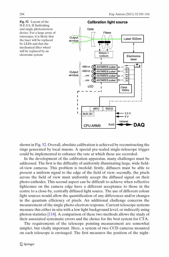
294 Exp Astron (2011) 32:193–316
Fig. 52 Layout of theH.E.S.S. II flatfieldingand single photoelectrondevice. For a large array oftelescopes, it is likely thatthe laser will be replacedby LEDs and that themechanical filter wheelwill be replaced by anelectronic system
shown in Fig. 52. Overall, absolute calibration is achieved by reconstructing therings generated by local muons. A special pre-scaled single-telescope triggercould be implemented to enhance the rate at which these are recorded.
In the development of the calibration apparatus, many challenges must beaddressed. The first is the difficulty of uniformly illuminating large, wide field-of-view cameras. This problem is twofold: firstly, diffusers must be able topresent a uniform signal to the edge of the field of view; secondly, the pixelsacross the field of view must uniformly accept the diffused signal on theirphoto-cathodes. This second aspect can be difficult to achieve when reflectivelightcones on the camera edge have a different acceptance to those in thecentre to a close-by, centrally diffused light source. The use of different colourlight sources would allow the quantification of any differences and/or changesin the quantum efficiency of pixels. An additional challenge concerns themeasurement of the single photo-electron response. Current telescope systemsmeasure this either in-situ with a low light background level, or indirectly usingphoton statistics [114]. A comparison of these two methods allows the study oftheir associated systematic errors and the choice for the best system for CTA.
The requirements of the telescope pointing measurement are somewhatsimpler, but vitally important. Here, a system of two CCD cameras mountedon each telescope is envisaged. The first measures the position of the night-
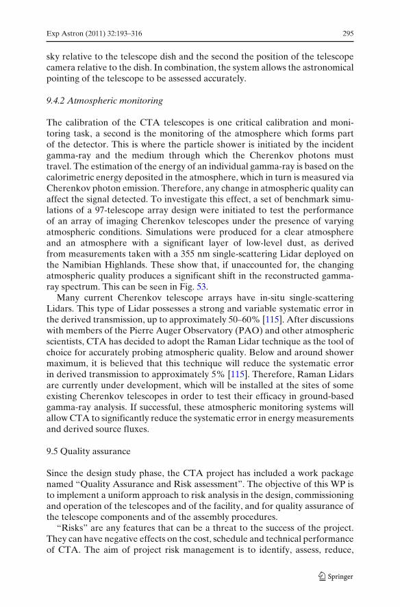
Exp Astron (2011) 32:193–316 295
sky relative to the telescope dish and the second the position of the telescopecamera relative to the dish. In combination, the system allows the astronomicalpointing of the telescope to be assessed accurately.
9.4.2 Atmospheric monitoring
The calibration of the CTA telescopes is one critical calibration and moni-toring task, a second is the monitoring of the atmosphere which forms partof the detector. This is where the particle shower is initiated by the incidentgamma-ray and the medium through which the Cherenkov photons musttravel. The estimation of the energy of an individual gamma-ray is based on thecalorimetric energy deposited in the atmosphere, which in turn is measured viaCherenkov photon emission. Therefore, any change in atmospheric quality canaffect the signal detected. To investigate this effect, a set of benchmark simu-lations of a 97-telescope array design were initiated to test the performanceof an array of imaging Cherenkov telescopes under the presence of varyingatmospheric conditions. Simulations were produced for a clear atmosphereand an atmosphere with a significant layer of low-level dust, as derivedfrom measurements taken with a 355 nm single-scattering Lidar deployed onthe Namibian Highlands. These show that, if unaccounted for, the changingatmospheric quality produces a significant shift in the reconstructed gamma-ray spectrum. This can be seen in Fig. 53.
Many current Cherenkov telescope arrays have in-situ single-scatteringLidars. This type of Lidar possesses a strong and variable systematic error inthe derived transmission, up to approximately 50–60% [115]. After discussionswith members of the Pierre Auger Observatory (PAO) and other atmosphericscientists, CTA has decided to adopt the Raman Lidar technique as the tool ofchoice for accurately probing atmospheric quality. Below and around showermaximum, it is believed that this technique will reduce the systematic errorin derived transmission to approximately 5% [115]. Therefore, Raman Lidarsare currently under development, which will be installed at the sites of someexisting Cherenkov telescopes in order to test their efficacy in ground-basedgamma-ray analysis. If successful, these atmospheric monitoring systems willallow CTA to significantly reduce the systematic error in energy measurementsand derived source fluxes.
9.5 Quality assurance
Since the design study phase, the CTA project has included a work packagenamed “Quality Assurance and Risk assessment”. The objective of this WP isto implement a uniform approach to risk analysis in the design, commissioningand operation of the telescopes and of the facility, and for quality assurance ofthe telescope components and of the assembly procedures.
“Risks” are any features that can be a threat to the success of the project.They can have negative effects on the cost, schedule and technical performanceof CTA. The aim of project risk management is to identify, assess, reduce,
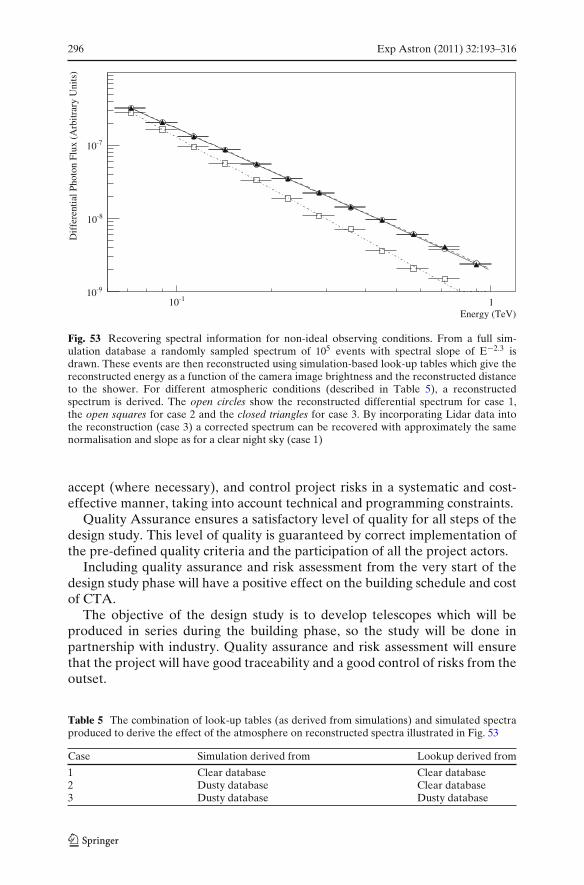
296 Exp Astron (2011) 32:193–316
Energy (TeV)
-110 1
Dif
fere
ntia
l Pho
ton
Flux
(A
rbitr
ary
Uni
ts)
-910
-810
-710
Fig. 53 Recovering spectral information for non-ideal observing conditions. From a full sim-ulation database a randomly sampled spectrum of 105 events with spectral slope of E−2.3 isdrawn. These events are then reconstructed using simulation-based look-up tables which give thereconstructed energy as a function of the camera image brightness and the reconstructed distanceto the shower. For different atmospheric conditions (described in Table 5), a reconstructedspectrum is derived. The open circles show the reconstructed differential spectrum for case 1,the open squares for case 2 and the closed triangles for case 3. By incorporating Lidar data intothe reconstruction (case 3) a corrected spectrum can be recovered with approximately the samenormalisation and slope as for a clear night sky (case 1)
accept (where necessary), and control project risks in a systematic and cost-effective manner, taking into account technical and programming constraints.
Quality Assurance ensures a satisfactory level of quality for all steps of thedesign study. This level of quality is guaranteed by correct implementation ofthe pre-defined quality criteria and the participation of all the project actors.
Including quality assurance and risk assessment from the very start of thedesign study phase will have a positive effect on the building schedule and costof CTA.
The objective of the design study is to develop telescopes which will beproduced in series during the building phase, so the study will be done inpartnership with industry. Quality assurance and risk assessment will ensurethat the project will have good traceability and a good control of risks from theoutset.
Table 5 The combination of look-up tables (as derived from simulations) and simulated spectraproduced to derive the effect of the atmosphere on reconstructed spectra illustrated in Fig. 53
Case Simulation derived from Lookup derived from
1 Clear database Clear database2 Dusty database Clear database3 Dusty database Dusty database

Exp Astron (2011) 32:193–316 297
This WP is managed by a coordinator who defines standards and qualitymethods for the project. To ensure the implementation of quality in the projectlaboratories, “Local Quality Correspondents” (LQCs) will be identified andtrained. These people will dedicate part of their time to quality issues, propor-tional to their laboratory participation in the overall project.
The main tasks of the WP participants are:
• To define the quality insurance organisation (the roles of the participants)• To ensure that quality control and risk analysis procedures are defined and
applied uniformly across the project to ensure high quality and reliabilityof hardware and software
• To ensure that the risk analysis, including dependability (reliability,availability, maintenance and safety) is defined based on the technicalconfiguration proposed
• To ensure support and expertise to implement the quality system andassociated tools across the project
• To verify the coherence of the procedures and protocols in order toapprove them for subsequent release and use
• To verify the application of the quality procedures across the project• To identify and reduce technical and management risks
Quality assurance and risk assessment concern the whole project. Thus, themembers of “Quality assurance and risk assessment” will have active links toall work packages, to the project management and to all laboratories involvedin building parts of CTA.
10 CTA site selection
Selection of sites for CTA is obviously crucial for achieving optimum per-formance and science output. Criteria for site selection include, among oth-ers, geographical conditions, observational and environmental conditions andquestions of logistics, accessibility, availability, stability of the host region, andlocal support:
Geographical conditions For best sky coverage, the latitude of the sites shouldbe around 30◦ north and south, respectively. The sites have to provide areasonably flat area of about 1 km2 (north) and at least 10 km2 (south).Optimum overall performance is obtained for site altitudes between about1,500 and 4,000 m. Even higher altitudes allow further reduction of theenergy threshold [93] at the expense of performance at medium and highenergies and might be considered for the northern array. Desirable is alsoa low component of geomagnetic field parallel to the surface, since suchfields deflect air shower particles.
Observational conditions Obviously, the fraction of clear nights should behigh. For good sites, this fraction is well above 60%, reaching up to 80%for the very best sites. Artificial light pollution must be well below the
298 Exp Astron (2011) 32:193–316
natural level of night sky background, which excludes sites within sometens of km of major population centres. Atmospheric transparency shouldbe good, implying dry locations with low amounts of aerosols and dust inthe atmosphere.
Environmental conditions Environment and climate influences both the op-erational efficiency and the survival conditions of the instrument. Windspeeds above 10 m/s may impact observations; peak wind speeds, whichmay range from below 100 km/h to beyond 200 km/h depending on thesite, have a major impact on telescope structure and cost. Sand stormsand hail represent a major danger for unprotected mirror surfaces. Snowand ice prevent observations and will influence instrument costs, e.g.by making heating systems necessary and requiring increased structuralstability. Seismic activity will similarly increase requirements on telescopestructures and buildings.
Infrastructure and logistics A well-developed infrastructure, e.g. as a result ofalready existing observatories, is an advantage. Connection to the powergrid and high speed internet access are mandatory. There should begood access to the site, i.e. nearby airports for air travel to/from Europeand elsewhere, and local access roads. A major population centre withtechnical and commercial infrastructure within convenient travel distanceis desirable.
Other criteria These include availability of the site for construction, guaranteesfor long-term operation and access, political stability of the host region,safety of personnel, both during travel and stay, and availability of localadministrative, technical and funding support as well as possibilities forscientific cooperation with local groups.
For both the observational and the environmental conditions, a long-term(multi-year) data record is required to allow dependable decisions o bemade. While archival remote-sensing data can provide some information, well-explored sites with existing installations and good records are favoured. It isunlikely that any site is optimal in all respects, so the different criteria willhave to be balanced against each other. Reliable and efficient operation of theobservatory should be a key criterion.
Site evaluation includes a number of different approaches, at differentstages of progress for a candidate site:
• Use of remote-sensing archival data and local archival data to evaluateobserving conditions and environmental conditions.
• Site visits and information gathering by local collaborating groups onlogistics aspects.
• Dedicated CTA measurements; since long-term measurements are ex-cluded, this approach is useful only for those quantities where shortcampaigns can provide meaningful results, such as the determination ofnatural and artificial night-sky brightness.
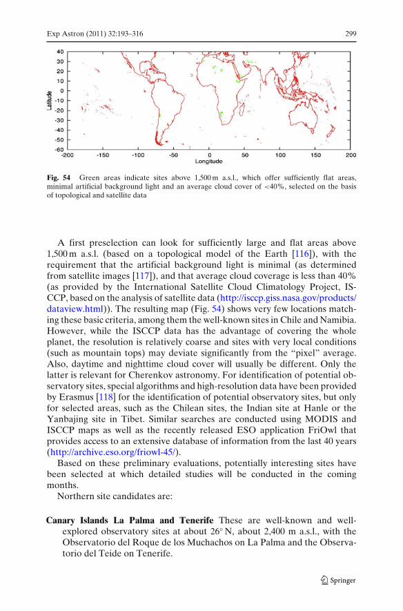
Exp Astron (2011) 32:193–316 299
Fig. 54 Green areas indicate sites above 1,500 m a.s.l., which offer sufficiently flat areas,minimal artificial background light and an average cloud cover of <40%, selected on the basisof topological and satellite data
A first preselection can look for sufficiently large and flat areas above1,500 m a.s.l. (based on a topological model of the Earth [116]), with therequirement that the artificial background light is minimal (as determinedfrom satellite images [117]), and that average cloud coverage is less than 40%(as provided by the International Satellite Cloud Climatology Project, IS-CCP, based on the analysis of satellite data (http://isccp.giss.nasa.gov/products/dataview.html)). The resulting map (Fig. 54) shows very few locations match-ing these basic criteria, among them the well-known sites in Chile and Namibia.However, while the ISCCP data has the advantage of covering the wholeplanet, the resolution is relatively coarse and sites with very local conditions(such as mountain tops) may deviate significantly from the “pixel” average.Also, daytime and nighttime cloud cover will usually be different. Only thelatter is relevant for Cherenkov astronomy. For identification of potential ob-servatory sites, special algorithms and high-resolution data have been providedby Erasmus [118] for the identification of potential observatory sites, but onlyfor selected areas, such as the Chilean sites, the Indian site at Hanle or theYanbajing site in Tibet. Similar searches are conducted using MODIS andISCCP maps as well as the recently released ESO application FriOwl thatprovides access to an extensive database of information from the last 40 years(http://archive.eso.org/friowl-45/).
Based on these preliminary evaluations, potentially interesting sites havebeen selected at which detailed studies will be conducted in the comingmonths.
Northern site candidates are:
Canary Islands La Palma and Tenerife These are well-known and well-explored observatory sites at about 26◦ N, about 2,400 m a.s.l., with theObservatorio del Roque de los Muchachos on La Palma and the Observa-torio del Teide on Tenerife.
300 Exp Astron (2011) 32:193–316
Hanle in India, in the Western Himalayas This high-altitude site (33◦ N, 4,500 ma.s.l.) hosts a small observatory and an array of Cherenkov instrumentswhich is deployed by Indian groups.
San Pedro Martir, Baja California Well-established astronomical site thathosts already two observatories run by UNAM (Universidad Autonomade Mexico). It is situated at about 31◦ N, at 2,800 m a.s.l.
Southern site candidates are:
Khomas Highland of Namibia This is a well-known astronomical site, at 1,800m a.s.l. and 23◦S, and is the home of the H.E.S.S. instrument. The regionoffers a range of suitable, large and flat areas.
Chilean sites Chile is home to some of the World’s premier optical observa-tories. However, availability of sufficiently large cites near these locationsis limited. A possible site is north of La Silla at 29◦S and 2,400 m a.s.l.Another potential site is near Cerro Paranal, with even better observingconditions, but no sufficiently flat area in this region has been identified sofar.
El Leoncito Reserve in Argentina This site is at 32◦S and 2,600 m a.s.l. andhosts the El Leoncito Astronomical Observatory.
Puna Highland in Argentina The region offers some large sites at 3,700 m a.s.l.with sky quality equivalent to the best Chilean ones. These sites have goodaccess to a railway line.
The final decision among otherwise identical sites may rely on considera-tions such as financial or in-kind contributions by the host regions. It is likelythat an inter-governmental agreement will be required to assure long-termavailability of the site, as well as guaranteed access and free transfer of data.At the same level, issues such as import taxes, value added tax and fees etc.should be addressed. Such agreements exist, for H.E.S.S., Auger and otherobservatories operated by international collaborations.
11 Outlook
The Cherenkov Telescope Array was conceived back in 2005, and was thenpromoted by members of the HESS and MAGIC collaborations. It wassoon apparent that a gamma-ray observatory could be designed with existingtechnologies that was much more powerful than any of the existing facilities.An improvement of a factor of 10 in sensitivity around a TeV and an extensionof the energy range from a few tens of GeV to >100 TeV, well beyond thecurrently accessible range, was achievable with an array of a large number(≈100) of differently sized telescopes.
With the results from current Cherenkov telescopes pouring in, it becameobvious that with such an instrument a vast number of sources of very differenttypes could be discovered and studied with unprecedented precision. Answersto long-standing questions in a number of science areas seemed possible. The
Exp Astron (2011) 32:193–316 301
extent and the diversity of the science case was, and is, stunning (see Section 3).CTA would truly be the first large open observatory for astronomy of theextreme universe beyond the GeV range.
Not surprisingly, many scientists were attracted to CTA and its science grewrapidly, as did the number of supporters who now form a large internationalcollaboration which is investigating how best to realise the project. CTA hasreceived consistently excellent reviews and high rankings in Science Roadmapsin Europe and across the world. CTA is an acknowledged ESFRI project,features high on the roadmaps of future projects of ApPEC, ASPERA andASTRONET and has been well received by national funding agencies. Thepotential of CTA is well recognised outside Europe, with the USA, Japan,India, Brazil and Argentina, and other countries contributing significantly.The US Decadal Survey endorsed a strong US participation in CTA asone of the four most important ground based initiatives in the next tenyears.
Since 2006, and specifically in a 4-year design study, it has been shownthat CTA, with observatories in the northern and southern hemisphere, canbe built to achieve its goal performance, at an investment cost in the rangeof 150 Me, which is a modest price for an installation of such scientificpotential.
CTA has recently received substantial funding from the European Commu-nity, for preparing for construction and operation, and from national fundingagencies, for development and prototyping. There is much excitement amongstall participants, and the wider science community, about the prospects thatCTA will soon from design to reality.
In this report, an account of the main design work performed so far ispresented, which constitutes a solid basis for the prototyping and constructionphases that lie ahead. The Preparatory Phase (3 years) and the subsequentconstruction phase (2013–2018) will pose many challenges. But CTA is a well-organised international collaboration of 25 countries and >600 scientists withextensive expertise in all relevant areas. Its members are eager and ready totackle the problems that lie ahead.
This effort is well worth it, as CTA will provide a huge science return inastrophysics, particle physics, cosmology and fundamental physics, and lead toa bright future for ground-based gamma ray astronomy.
Acknowledgements We gratefully acknowledge financial support from the following agen-cies and organisations: Ministerio de Ciencia, Tecnología e Innovación Productiva (MinCyT),Comisión Nacional de Energía Atómica (CNEA) and Consejo Nacional de InvestigacionesCientíficas y Técnicas (CONICET) Argentina; State Committee of Science of Armenia; Ministryfor Research, CNRS-INSU, CNRS-IN2P3 and CEA, France; Max Planck Society, BMBF, DESY,Helmholtz Association, Germany; MIUR, Italy; Netherlands Research School for Astronomy(NOVA), Netherlands Organization for Scientific Research (NWO); Ministry of Science andHigher Education and the National Centre for Research and Development, Poland; MICINNsupport through the National R+D+I, CDTI funding plans and the CPAN and MultiDarkConsolider-Ingenio 2010 programme, Spain. Swedish Research Council, Royal Swedish Academyof Sciences financed, Sweden; Swiss National Science Foundation (SNSF), Switzerland; Lever-hulme Trust, Royal Society, Science and Technologies Facilities Council, Durham University, UK;
302 Exp Astron (2011) 32:193–316
National Science Foundation, Department of Energy, Argonne National Laboratory, Universityof California, University of Chicago, Iowa State University, Institute for Nuclear and ParticleAstrophysics (INPAC-MRPI program), Washington University McDonnell Center for the SpaceSciences, USA.
Open Access This article is distributed under the terms of the Creative Commons AttributionNoncommercial License which permits any noncommercial use, distribution, and reproduction inany medium, provided the original author(s) and source are credited.
References
1. See, e.g., Aharonian, F.A.: The H.E.S.S. survey of the inner galaxy in very high energy gammarays. Astrophys. J. 636, 777 (2006) (and subsequent presentations in conferences)
2. Barrau, A., et al.: The CAT imaging telescope for very-high-energy gamma-ray astronomy.NIMPA 416, 278 (1998)
3. See, e.g., Aharonian, F.A.: The energy spectrum of TEV gamma rays from the Crab Nebulaas measured by the HEGRA system of imaging air cerenkov telescopes. Astrophys. J. 539,317 (2000)
4. Aharonian, F.A., Völk, H.J., Horns, D. (eds.): Proc. 2nd Int. Meeting on High EnergyGamma-Ray Astronomy Heidelberg (2004). AIP Conference Proceedings, vol. 745 (2004)
5. Aharonian, F.A., Hofmann, W., Rieger, F. (eds.): Proc. 4th Int. Meeting on High EnergyGamma-Ray Astronomy, Heidelberg (2008). AIP Conference Proceedings, vol. 1085 (2008)
6. Hinton, J.A., Hofmann, W.: Teraelectronvolt astronomy. Annu. Rev. Astron. Astrophys. 47,523 (2009)
7. Aharonian, F.A., et al.: High energy astrophysics with ground-based gamma ray detectors.Rep. Prog. Phys. 71, 096901 (2008)
8. Buckley, J., et al.: The Status and future of ground-based TeV gamma-ray astronomy. AWhite Paper prepared for the division of Astrophysics of the American physical society,AGIS White Paper. arXiv:0810.0444v1
9. 2nd Fermi Symposium, Washington, Capitol Hill, eConf Proceedings C091122.http://www.slac.stanford.edu/econf/C0911022/ (2009)
10. Reynolds, S.P.: Supernova remnants at high energy. Annu. Rev. Astron. Astrophys. 46, 89(2008)
11. Malkov, M.A., Drury, L.O’C.: Nonlinear theory of diffusive acceleration of particles by shockwaves. Rep. Prog. Phys. 64, 429 (2001)
12. Aharonian, F.A., Atoyan, A.M.: On the emissivity of π0-decay gamma radiation in thevicinity of accelerators of galactic cosmic rays. Astron. Astrophys. 309, 917 (1996)
13. Gabici, S., Aharonian, F.A., Blasi, P.: Gamma ray signatures of ultra high energy cosmic rayaccelerators: electromagnetic cascade versus synchrotron radiation of secondary electrons.Astrophys. Space Sci. 309, 365 (2007)
14. 31st ICRC, Łódz, Poland. http://icrc2009.uni.lodz.pl/ (2009)15. Aharonian, F.A., et al.: Energy dependent γ -ray morphology in the pulsar wind nebula HESS
J1825-137. Astron. Astrophys. 460, 365 (2006)16. Dalton, M., et al.: Presentation at TeV Particle Astrophysics 2010, Paris (2010)17. Aharonian, F.A., et al.: First detection of a VHE gamma-ray spectral maximum from a cosmic
source: HESS discovery of the Vela X nebula. Astron. Astrophys. 448, L43 (2006)18. Gaensler, B.M., Slane, P.O.: The evolution and structure of pulsar wind nebulae. Annu. Rev.
Astron. Astrophys. 44, 17 (2006)19. de Jager, O.C., Djannati-Atai, A.: In: Becker, W. (ed.) Springer Lecture Notes on “Neutron
Stars and Pulsars: 40 Years After Their Discovery”. arXiv:0803.0116v1 (2008)20. Aharonian, F.A., et al.: Very high energy gamma rays from the direction of Sagittarius A∗.
Astron. Astrophys. 425, L13 (2004)21. Albert, J., et al.: Observation of gamma rays from the galactic center with the MAGIC
telescope. Astrophys. J. 638 (2006) L101 638, L101 (2006)
Exp Astron (2011) 32:193–316 303
22. Zhang, J.L., Bi, X.J., Hu, H.B.: Very high energy γ ray absorption by the galactic interstellarradiation field. Astron. Astrophys. 449, 641 (2006)
23. Abdo, A., et al.: Fermi LAT Observations of LS I +61’303: First Detection of an OrbitalModulation in GeV Gamma Rays. Astrophys. J. 701, L123 (2009)
24. Fender, R.: Jets from X-ray binaries. In: Lewin, W.H.G., van der Klis, M. (eds.) CompactStellar X-Ray Sources. Cambridge University Press, Cambridge (2003)
25. Levinson, A.: High-energy aspects of astrophysical jets. Int. J. Mod. Phys. A21, 6015 (2006)26. Butt, Y.: Beyond the myth of the supernova-remnant origin of cosmic rays. Nature 460, 701
(2009)27. Marti, J.: Proc. High Energy Phenomena in Massive Stars. University of Jaen. ASP Confer-
ence Series, vol. 422. ISBN: 978-1-58381-724-7 (2010)28. Aliu, E., et al.: Science 322, 1222 (2009)29. Rea, N., Torres, D.F. (eds.): Proc. 1st Session of the Sant Cugat Forum of Astrophysics:
ICREA International Workshop on The High-Energy Emission from Pulsars and TheirSystems. Springer. ISSN:1570-6591 (2010)
30. Jones, T.W., O’Dell, S.L., Stein, W.A.: Physics of compact nonthermal sources. Theory ofradiation rocesses. Astrophys. J. 188, 353 (1974)
31. Pian, E., et al.: BeppoSAX observations of unprecedented synchrotron activity in the BLlacertae object markarian 501. Astrophys. J. 492, L17 (1998)
32. Kino, M., Takahara, F., Kusunose, M.: Energetics of TeV blazars and physical constraints ontheir emission regions. Astrophys. J. 564, 97 (2002)
33. Dermer, C.D., Schlickeiser, R.: Model for the high-energy emission from blazars. Astrophys.J. 416, 458 (1993)
34. Sikora, M., Begelman, M.C., Rees, M.J.: Comptonization of diffuse ambient radiation by arelativistic jet: The source of gamma rays from blazars? Astrophys. J. 421, 153 (1994)
35. Mannheim, K., Biermann, P.L., Kruells, W.M.: A novel mechanism for nonthermal X-rayemission. Astron. Astrophys. 251, 723 (1991)
36. Aharonian, F.A.: TeV gamma rays from BL Lac objects due to synchrotron radiation ofextremely high energy protons. New Astron. 5, 377 (2000)
37. See, e.g., Aharonian, F.A., et al.: Fast variability of tera-electron volt γ rays from the radiogalaxy M87. Science 314, 1424 (2006)
38. See, e.g., Miralda Escude, J.: The dark age of the universe. Science 300, 1904 (2000)39. Romero, G.E., Aharonian, F.A., Paredes, J.M. (eds.): Proc. High-Energy Phenomena in
Relativistic Outflows II, Buenos Aires, Argentina (2009); Int. J. Mod. Phys. D19, 635–1048(2010); http://hepro2.iar-conicet.gov.ar/talks.html
40. Krolik, J.H., Pier, E.A.: Relativistic motion in gamma-ray bursts. Astrophys. J. 373, 277(1991)
41. Fenimore, E.E., Epstein, R.I., Ho, C.: The escape of 100 MeV photons from cosmologicalgamma-ray bursts. Astron. Astrophys. 97, 59 (1993)
42. Woods, E., Loeb, A.: Empirical constraints on source properties and host galaxies of cosmo-logical gamma-ray bursts. Astrophys. J. 453, 583 (1995)
43. See, e.g., Berger, E., et al.: The afterglow and elliptical host galaxy of the short γ -ray burstGRB 050724. Nature 438, 988 (2005)
44. See, e.g., MacFadyen, A.I., Woosley, S.E.: Collapsars: Gamma-ray bursts and explosions in“failed supernovae”, Astrophys. J. 524, 262 (1999)
45. See, e.g., Blasi, P., Amato, E., Caprioli, D.: The maximum momentum of particles acceleratedat cosmic ray modified shocks. Mon. Not. R. Astron. Soc. 375, 1471 (2007)
46. Bertone, G. (eds.): Particle Dark Matter. Cambridge University Press, Cambridge. ISBN13:9780521763684 (2010)
47. Adriani, O., et al.: An anomalous positron abundance in cosmic rays with energies 1.5-100GeV. Nature 458, 607 (2009)
48. Abdo, A., et al.: Measurement of the Cosmic Ray e++e− Spectrum from 20GeV to 1TeVwith the Fermi Large Area Telescope. Phys. Rev. Lett. 102, 181101 (2009)
49. Abdo, A., et al.: A limit on the variation of the speed of light arising from quantum gravityeffects. Nature 462, 331 (2009)
50. Martinez, M.: Fundamental physics with cosmic gamma rays. J. Phys. Conf. Ser. 171, 012013(2009)
51. Hanbury Brown, R.: The intensity interferometer. Taylor & Francis, London (1974)

304 Exp Astron (2011) 32:193–316
52. Le Bohec, S., Holder, J.: Optical intensity interferometry with atmospheric cerenkov tele-scope arrays. Astrophys. J. 649, 399 (2006)
53. Herbst, W., Shevchenko, K.S.: A photometric catalog of herbig AE/BE Stars and discussionof the nature and cause of the variations of UX orionis stars. Astron. J. 118, 1043 (1999)
54. Kieda, D.B., Swordy, S.P., Wakely, S.P.: A high resolution method for measuring cosmic raycomposition beyond 10 TeV, Astropart. Astropart. Phys. 15, 287 (2001)
55. Aharonian, F.A., et al.: First ground-based measurement of atmospheric Cherenkov lightfrom cosmic rays. Phys. Rev. D 75, 042004 (2007)
56. Hinton, J.: Ground-based gamma-ray astronomy with Cherenkov telescopes. New J. Phys.11, 055005 (2009)
57. Hinton, J., et al. (H.E.S.S. Collaboration): Background modelling in ground-basedCherenkov astronomy. In: Proc. Towards a Network of Atmospheric Cherenkov DetectorsVII, Palaiseau, France, pp. 183–190 (2005)
58. Albert, J., et al. (MAGIC Collaboration): Very High Energy Gamma-Ray ObservationsDuring Moonlight and Twilight with the MAGIC Telescope [astro-ph/0702475]
59. Hofmann, W.: Performance limits for Cherenkov instruments. In: Proc. Towards a Networkof Atmospheric Cherenkov Detectors VII, Palaiseau, France [astro-ph/0603076] (2005)
60. Maier, G., Knapp, J.: Cosmic-ray events as background in imaging atmospheric Cherenkovtelescopes. Astropart. Phys. 28, 72 [astro-ph/0704.3567] (2007)
61. Amsler, C., et al. (Particle Data Group): Phys. Lett. B 667, 1 (2008) (Section 27.5. Electro-magnetic cascades, p. 276)
62. Aharonian, F.A., et al. (H.E.S.S. Collaboration): First ground-based measurement of at-mospheric Cherenkov light from cosmic rays. Phys. Rev. D 75, 042004 (2007)
63. Sahakian, V., Aharonian, F., Akhperjanian, A.: Cherenkov light in electron-induced airshowers. Astropart. Phys. 25, 233 (2006)
64. Aliu, E., et al.: Improving the performance of the single-dish Cherenkov telescope MAGICthrough the use of signal timing. Astropart. Phys. 30, 293 (2009)
65. Schliesser, A., Mirzoyan, R.: Wide-field prime-focus imaging atmospheric Cherenkov tele-scopes: A systematic study. Astropart. Phys. 24, 382 (2005)
66. Vassiliev, V.V., Fegan, S.J., Brousseau, P.F.: Wide field aplanatic two-mirror telescopes forground-based γ -ray astronomy. Astropart. Phys. 28, 10 [astro-ph/0612718] (2007)
67. Aharonian, F., et al.: On the optimization of multichannel cameras for imaging atmosphericCherenkov telescopes. J. Phys. G 21, 985 (1995)
68. de Naurois, M., Rolland, L.: A high performance likelihood reconstruction of γ -rays forimaging atmospheric Cherenkov telescopes. Astropart. Phys. 32, 231 (2009)
69. Albert, J., et al.: FADC signal reconstruction for the MAGIC telescope. Nucl. Instrum.Methods A594, 407 (2008)
70. Mirzoyan, R., et al.: Tagging single muons and other long-flying relativistic charged particlesby ultra-fast timing in air Cherenkov telescopes. Astropart. Phys. 25, 342 (2006)
71. Albert, J., et al. (MAGIC Collaboration): FADC signal reconstruction for the MAGICtelescope. Nucl. Instrum. Methods A594, 407–419 [astro-ph/0612385] (2008)
72. Funk, S., et al.: The trigger system of the H.E.S.S. telescope array. Astropart. Phys. 22, 285[astro-ph0408375] (2004)
73. Heck, D., et al.: CORSIKA: a Monte Carlo code to simulate extensive air showers.Technical Report FZKA 6019, Forschungszentrum Karlsruhe. http://www-ik.fzk.de/corsika/(1998)
74. Kertzman, M.P., Sembroski, G.H.: Computer simulation methods for investigating the de-tection characteristics of TeV air Cherenkov telescopes. Nucl. Instrum. Methods A343, 629(1994)
75. Bernlöhr, K.: Simulation of imaging atmospheric Cherenkov telescopes with CORSIKA andsim_telarray. Astropart. Phys. 30, 149 (2008)
76. Guy, J.: Premiers résultats de l’expérience HESS et étude du potentiel de détection dematière noire supersymétrique. Thèse de doctorat, Université Paris V (2003)
77. Majumdar, P., et al.: Monte Carlo simulations for the MAGIC telescope. In: Proc. 29th ICRC,Pune, vol. 5, p. 203 (2005)
78. Hillas, M.: Cerenkov light images of EAS produced by primary gamma. Proc. 19th ICRC, LaJolla, vol. 3, p. 445 (1985)
Exp Astron (2011) 32:193–316 305
79. Bock, R.K., Chilingarian, A., Gaug, M., et al.: Methods for multidimensional event clas-sification: a case study using images from a Cherenkov gamma-ray telescope. Nucl. Instrum.Methods A516, 511 (2004)
80. Ohm, S., van Eldik, C., Egberts, K.: γ /hadron separation in very-high-energy γ -ray astronomyusing a multivariate analysis method. Astropart. Phys. 31, 383 (2009)
81. Fiasson, A., Dubois, F., Masbou, J., Lamanna, G., Rosier-Lees, S.: Optimization of multivari-ate analysis for IACT stereoscopic systems. Astropart. Phys. 34, 25 (2010)
82. Lemoine-Goumard, M., Degrange, B., Tluczykont, M.: Selection and 3D-reconstruction ofgamma-ray-induced air showers with a stereoscopic system of atmospheric Cherenkov tele-scopes. Astropart. Phys. 25, 195 (2006)
83. Cornils, R., et al.: The optical system of the H.E.S.S. imaging atmospheric Cherenkov tele-scopes. Part II: mirror alignment and point spread function. Astropart. Phys. 20, 129 (2003)
84. Aharonian, F.A., et al.: An exceptional very high energy gamma-ray flare of PKS 2155-304.Astrophys. J. 664, L71 (2007)
85. Battistoni, G., et al.: The FLUKA code: description and benchmarking. Proc. HadronicShower Simulation Workshop 2006, Fermilab 2006. In: Albrow, M., Raja, R. (eds.) AIPConf. Proc., vol. 896, p. 31 (2007); Fasso, A., et al.: CERN-2005-10 (2005), INFN/TC_05/11,SLAC-R-773
86. Bass, S.A., et al.: Microscopic models for ultrarelativistic heavy ion collisions. Prog. Part.Nucl. Phys. 41, 225 (1998); Bleicher, M., et al.: Relativistic hadron-hadron collisions in theultra-relativistic quantum molecular dynamics model. J. Phys. G: Nucl. Part. Phys. 25, 1859(1999)
87. Kalmykov, N.N., et al.: Quark-gluon string model and EAS simulation problems at ultra-highenergies. Nucl. Phys. B (Proc. Suppl.) 52B, 17 (1997)
88. Ostapchenko, S.S.: QGSJET-II: towards reliable description of very high energy hadronicinteractions & QGSJET-II: results for extensive air showers. Nucl. Phys. B (Proc. Suppl.) 151143 and 147 (2006)
89. Ostapchenko, S.S.: Nonlinear screening effects in high energy hadronic interactions. Phys.Rev. D 74, 014026 (2006)
90. Engel, R., et al.: Air shower calculations with the new version of SIBYLL. Proc. 26th ICRC(Salt Lake City), vol. 1, p. 415 (1999)
91. Aharonian, F.A., et al.: Energy Spectrum of Cosmic-Ray Electrons at TeV Energies. Phys.Rev. Lett. 101, 261104 (2008)
92. Bernlöhr, K., et al.: MC Simulation and Layout Studies for a future Cherenkov TelescopeArray. Proc. 30th ICRC, Merida, vol. 3, p. 1469 (2007)
93. Aharonian, F.A., et al.: 5@5 - a 5 GeV energy threshold array of imaging atmosphericCherenkov telescopes at 5 km altitude. Astropart. Phys. 15, 335 (2001)
94. Konopelko, A.: Altitude effect in Cerenkov light flashes of low energy gamma-ray-inducedatmospheric showers. J. Phys. G: Nucl. Part. Phys. 30, 1835 (2004)
95. Funk, S., Hinton, J.A.: Monte-Carlo studies of the angular resolution of a future Cherenkovgamma-ray telescope. Proc. 4th Heidelberg Int. Symposium on High Energy Gamma-RayAstronomy 2008
96. Maier, G., et al. (AGIS Collaboration): The Advanced Gamma-ray Imaging System (AGIS):Simulation Studies. Proc. 32nd ICRC, Łódz, Poland. arXiv:0907.5118v1 (2009)
97. Funk, S.: A new population of very high-energy gamma-ray sources detected with H.E.S.S.in the inner part of the Milky Way. PhD Thesis, University of Heidelberg (2005)
98. Schwarzschild, K.: Untersuchungen zur geometrischen Optik II: Theorie der Spiegeltele-scope (1905); Abhandlungen der Gesellschaft der Wissenschaften in Göttingen, Bd 4, 2(1905) 1
99. Ritchey, G.W.: The Modern Photographic Telescope and the New Astronomical Photogra-phy. Comptes Rendus 185, 1024 (1927)
100. Davies, J.M., Cotton, E.S.: Design of the quartermaster solar furnace. J. Sol. Energy Sci. Eng.1, 16 (1957)
101. Bernlöhr, K., et al.: The optical system of the H.E.S.S. imaging atmospheric Cherenkovtelescopes. Part I: layout and components of the system. Astropart. Phys. 20, 111 (2003)
102. Biland, A., et al. (MAGIC Collaboration): The active mirror control of the MAGIC Tele-scopes. Proc. 30th ICRC Merida, vol. 3, p. 1353 (2007)
306 Exp Astron (2011) 32:193–316
103. Doro, M., et al.: The reflective surface of the MAGIC telescope. Nucl. Instrum. MethodsA595, 200 (2008)
104. Pareschi, G., et al.: Glass mirrors by cold slumping to cover 100 m2 of the MAGIC IICherenkov telescope reflecting surface. Proc. SPIE 7018, 70180W (2008)
105. Holder, J., et al.: The first VERITAS telescope. Astropart. Phys. 25, 391 (2006)106. Cogan, P., for the VERITAS Collaboration: Analysis of flash ADC data with VERITAS.
arXiv:0709.4208v2107. Punch, M., et al.: GigaHertz analogue memories in ground-based gamma-ray astronomy. AIP
Conf. Proc. 515, 373 (2000)108. Delagnes, E., et al.: A new GHz sampling ASIC for the H.E.S.S.-II front-end electronics.
Nucl. Instrum. Methods A567, 21 (2006)109. Tescaro, D., et al.: The readout system of the MAGIC-II Cherenkov telescope.
arXiv:0907.0466110. Hermann, G., et al.: A trigger and readout scheme for future Cherenkov Telescope Ar-
rays. Proc. 4th Heidelberg Int. Symposium on High Energy Gamma-Ray Astronomy 2008.arXiv:0812.0762
111. Aliu, E., et al. (MAGIC Collaboration): Observation of pulsed γ -Rays above 25 GeV fromthe Crab Pulsar with MAGIC. Science 322, 1221 (2008)
112. Aharonian, F., et al. (H.E.S.S. Collaboration): Calibration of cameras of the H.E.S.S. detec-tor. Astrop. Phys. 22, 109 (2004)
113. Digel, S., et al. for the AGIS Collaboration: Talk at 2009 SLAC Users Organisation Meeting.http://www-group.slac.stanford.edu/sluo/2009AnnualMeeting/Talks/Tajima.pdf
114. Hanna, D., et al.: An LED-based flasher system for VERITAS. Nucl. Instrum. MethodsA612, 278 (2009)
115. Papayannis, A., Fokitis, E.: Pierre Auger Observatory. Internal Note (1998) GAP 1998-018116. U.S. Geological Survey, GTOPO30, http://eros.usgs.gov/products/elevation/gtopo30.html117. Cinzano, P., Falchi, F., Elvidge, C.D.: The first World Atlas of the artificial night sky bright-
ness. MNRAS 328, 689 (2001)118. Erasmus, D.A.: An analysis of cloud cover and water vapor for the ALMA project.
www.eso.org/gen-fac/pubs/astclim/espas/radioseeing/ (2002); An analysis and comparisonof satellite-observed cloud cover and water vapor at Hanle, India and Yanbajing, Tibet.http://www.saao.ac.za/∼erasmus/Projects/MPIHimalaya/MPIHimalaya_overview.html(2004)
Exp Astron (2011) 32:193–316 307
The CTA Consortium
M. Actis3, G. Agnetta49, F. Aharonian48, A. Akhperjanian8, J. Aleksic107,E. Aliu151, D. Allan123, I. Allekotte1, F. Antico3, L.A. Antonelli55,P. Antoranz111, A. Aravantinos47, T. Arlen141, H. Arnaldi1, S. Artmann33,K. Asano84, H. Asorey1, J. Bähr35, A. Bais45, C. Baixeras108, S. Bajtlik95,D. Balis45, A. Bamba63, C. Barbier25, M. Barceló107, A. Barnacka95, J. Barnstedt43,U. Barres de Almeida42, J.A. Barrio112, S. Basso52, D. Bastieri58, C. Bauer41,J. Becerra102,103, Y. Becherini26, K. Bechtol138, J. Becker33, V. Beckmann20,W. Bednarek92, B. Behera35, M. Beilicke145, M. Belluso53, M. Benallou20,W. Benbow139, J. Berdugo104, K. Berger102,103, T. Bernardino111, K. Bernlöhr41,A. Biland120, S. Billotta53, T. Bird133, E. Birsin35,36, E. Bissaldi9, S. Blake125,O. Blanch107, A.A. Bobkov141, L. Bogacz93, M. Bogdan143, C. Boisson28,J. Boix107, J. Bolmont31, G. Bonanno53, A. Bonardi43, T. Bonev16,J. Borkowski95, O. Botner118, A. Bottani3, M. Bourgeat27, C. Boutonnet20,A. Bouvier142, S. Brau-Nogué22,23, I. Braun120, T. Bretz119, M.S. Briggs140,P. Brun21, L. Brunetti25, J.H. Buckley145, V. Bugaev145, R. Bühler138, T. Bulik94,G. Busetto58, S. Buson58, K. Byrum135, M. Cailles25, R. Cameron138,R. Canestrari52, S. Cantu52, E. Carmona104, A. Carosi55, J. Carr32,P.H. Carton21, M. Casiraghi52, H. Castarede30, O. Catalano49, S. Cavazzani51,S. Cazaux21, B. Cerruti24, M. Cerruti28, P.M. Chadwick123, J. Chiang138,M. Chikawa69, M. Cieslar94, M. Ciesielska98, A. Cillis2, C. Clerc26, P. Colin42,J. Colomé105, M. Compin27, P. Conconi52, V. Connaughton140, J. Conrad115,J.L. Contreras112, P. Coppi153, M. Corlier20, P. Corona31, O. Corpace21,D. Corti58, J. Cortina107, H. Costantini32, G. Cotter134, B. Courty20,S. Couturier26, S. Covino52, J. Croston133, G. Cusumano49, M.K. Daniel123,F. Dazzi61, A. de Angelis60, E. de Cea del Pozo105, E.M. de Gouveia Dal Pino12,O. de Jager101,†, I. de la Calle Pérez113, G. De La Vega4,5,B. De Lotto60, M. de Naurois26, E. de Oña Wilhelmi41, V. de Souza13,B. Decerprit35, C. Deil41, E. Delagnes21, G. Deleglise25, C. Delgado104,T. Dettlaff42, A. Di Paolo55, F. Di Pierro50, C. Díaz104, J. Dick43,H. Dickinson115, S.W. Digel138, D. Dimitrov16, G. Disset21, A. Djannati-Ataï20,M. Doert37, W. Domainko41, D. Dorner121, M. Doro58,108, J.-L. Dournaux29,D. Dravins114, L. Drury48, F. Dubois112, R. Dubois138, G. Dubus24, C. Dufour20,D. Durand21, J. Dyks95, M. Dyrda96, E. Edy26, K. Egberts9, C. Eleftheriadis45,S. Elles25, D. Emmanoulopoulos133, R. Enomoto85, J.-P. Ernenwein32,M. Errando151, A. Etchegoyen4,5, A.D. Falcone147, K. Farakos47, C. Farnier121,S. Federici34,35, F. Feinstein27, D. Ferenc149, E. Fillin-Martino26, D. Fink42,C. Finley115, J.P. Finley148, R. Firpo107, D. Florin122, C. Föhr41, E. Fokitis47,Ll. Font108, G. Fontaine26, A. Fontana55, A. Förster41, L. Fortson150,N. Fouque25, C. Fransson116, G.W. Fraser126, L. Fresnillo111, C. Fruck42,Y. Fujita79, Y. Fukazawa64, S. Funk138, W. Gäbele43, S. Gabici20, A. Gadola122,N. Galante139, Y. Gallant27, B. García4,5, R.J. García López102,103,
†deceased.

308 Exp Astron (2011) 32:193–316
D. Garrido108, L. Garrido110, D. Gascón110, C. Gasq25, M. Gaug108, J. Gaweda107,N. Geffroy25, C. Ghag129, A. Ghedina57, M. Ghigo52, E. Gianakaki45,S. Giarrusso49, G. Giavitto107, B. Giebels26, E. Giro54, P. Giubilato58,T. Glanzman138, J.-F. Glicenstein21, M. Gochna94, V. Golev15,M. Gómez Berisso1, A. González107, F. González6, F. Grañena107,R. Graciani110, J. Granot131, R. Gredig122, A. Green128, T. Greenshaw127,O. Grimm120, J. Grube146, M. Grudzinska94, J. Grygorczuk98, V. Guarino135,L. Guglielmi20, F. Guilloux21, S. Gunji87, G. Gyuk146, D. Hadasch105,D. Haefner42, R. Hagiwara87, J. Hahn41, A. Hallgren118, S. Hara88,M.J. Hardcastle131, T. Hassan112, T. Haubold42, M. Hauser40, M. Hayashida72,R. Heller35, G. Henri24, G. Hermann41, A. Herrero102,103, J.A. Hinton126,D. Hoffmann32, W. Hofmann41, P. Hofverberg41, D. Horns39, D. Hrupec17,H. Huan143, B. Huber122, J.-M. Huet29, G. Hughes35, K. Hultquist115,T.B. Humensky143, J.-F. Huppert31, A. Ibarra113, J.M. Illa107, J. Ingjald114,S. Inoue85, Y. Inoue72, K. Ioka68, C. Jablonski42, A. Jacholkowska31,M. Janiak95, P. Jean22,23, H. Jensen114, T. Jogler42, I. Jung38, P. Kaaret152,S. Kabuki82, J. Kakuwa64, C. Kalkuhl43, R. Kankanyan41, M. Kapala94,A. Karastergiou134, M. Karczewski98, S. Karkar32, N. Karlsson150,J. Kasperek99, H. Katagiri66, K. Katarzynski97, N. Kawanaka68, B. Kedziora98,E. Kendziorra43, B. Khélifi26, D. Kieda144, T. Kifune85, T. Kihm41, S. Klepser107,W. Kluzniak95, J. Knapp125, A.R. Knappy123, T. Kneiske39, J. Knödlseder22,23,F. Köck41, K. Kodani81, K. Kohri68, K. Kokkotas45, N. Komin25,A. Konopelko137, K. Kosack21, R. Kossakowski25, P. Kostka35, J. Kotuła96,G. Kowal12, J. Kozioł93, T. Krähenbühl120, J. Krause42, H. Krawczynski145,F. Krennrich136, A. Kretzschmann35, H. Kubo73, V.A. Kudryavtsev130,J. Kushida81, N. La Barbera49, V. La Parola49, G. La Rosa49, A. López107,G. Lamanna25, P. Laporte29, C. Lavalley27, T. Le Flour25, A. Le Padellec22,23,J.-P. Lenain121, L. Lessio54, B. Lieunard25, E. Lindfors19, A. Liolios45,T. Lohse36, S. Lombardi58, A. Lopatin38, E. Lorenz42, P. Lubinski95, O. Luz43,E. Lyard121, M.C. Maccarone49, T. Maccarone133, G. Maier35, P. Majumdar141,S. Maltezos47, P. Małkiewicz93, C. Mañá104, A. Manalaysay122, G. Maneva14,A. Mangano49, P. Manigot26, J. Marín104, M. Mariotti58, S. Markoff91,G. Martínez104, M. Martínez107, A. Mastichiadis46, H. Matsumoto77, S. Mattiazzo58,D. Mazin107, T.J.L. McComb123, N. McCubbin132, I. McHardy133, C. Medina21,D. Melkumyan35, A. Mendes32, P. Mertsch134, M. Meucci59, J. Michałowski96,P. Micolon21, T. Mineo49, N. Mirabal112, F. Mirabel21, J.M. Miranda111,R. Mirzoyan42, T. Mizuno64, B. Moal26, R. Moderski95, E. Molinari57,I. Monteiro25, A. Moralejo107, C. Morello50, K. Mori75, G. Motta52,F. Mottez28, E. Moulin21, R. Mukherjee151, P. Munar109, H. Muraishi70,K. Murase85, A.StJ. Murphy129, S. Nagataki74, T. Naito88, T. Nakamori86,K. Nakayama68, C. Naumann31, D. Naumann35, P. Nayman31, D. Nedbal18,A. Niedzwiecki92, J. Niemiec96, A. Nikolaidis45, K. Nishijima81, S.J. Nolan123,N. Nowak42, P.T. O’Brien126, I. Ochoa3, Y. Ohira68, M. Ohishi85, H. Ohka85,A. Okumura67, C. Olivetto20, R.A. Ong141, R. Orito83, M. Orr136,J.P. Osborne126, M. Ostrowski93, L. Otero6, A.N. Otte142, E. Ovcharov15,I. Oya36, A. Oziebło100, S. Paiano58, J. Pallota6, J.L. Panazol25, D. Paneque42,
Exp Astron (2011) 32:193–316 309
M. Panter41, R. Paoletti59, G. Papyan8, J.M. Paredes109, G. Pareschi52,R.D. Parsons125, M. Paz Arribas35, G. Pedaletti105, A. Pepato58, M. Persic62,P.O. Petrucci24, B. Peyaud21, W. Piechocki93, S. Pita20, G. Pivato58,Ł. Płatos98, R. Platzer35, L. Pogosyan8, M. Pohl34,35, G. Pojmanski94,J.D. Ponz113, W. Potter134, E. Prandini58, R. Preece132, H. Prokoph35,G. Pühlhofer43, M. Punch20, E. Quel6, A. Quirrenbach40, P. Rajda99, R. Rando58,M. Rataj98, M. Raue39, C. Reimann40, O. Reimann42, A. Reimer9, O. Reimer9,M. Renaud27, S. Renner43, J.-M. Reymond21, W. Rhode37, M. Ribó109,M. Ribordy119, J. Rico106,107, F. Rieger41, P. Ringegni3, J. Ripken115,P. Ristori6, S. Rivoire27, L. Rob18, S. Rodriguez42, U. Roeser120, P. Romano49,G.E. Romero7, S. Rosier-Lees25, A.C. Rovero2, F. Roy28, S. Royer27,B. Rudak95, C.B. Rulten123, J. Ruppel34,35, F. Russo49, F. Ryde117,B. Sacco49, A. Saggion58, V. Sahakian8, K. Saito42, T. Saito42, N. Sakaki63,E. Salazar112, A. Salini52, F. Sánchez4,5, M.Á. Sánchez Conde102,103,A. Santangelo43, E.M. Santos11, A. Sanuy110, L. Sapozhnikov138, S. Sarkar134,V. Scalzotto58, V. Scapin60, M. Scarcioffolo58, T. Schanz43, S. Schlenstedt35,R. Schlickeiser33, T. Schmidt35, J. Schmoll124, M. Schroedter139, C. Schultz58,J. Schultze35, A. Schulz38, U. Schwanke36, S. Schwarzburg43, T. Schweizer42,J. Seiradakis45, S. Selmane20, K. Seweryn98, M. Shayduk35, R.C. Shellard10,T. Shibata63, M. Sikora95, J. Silk134, A. Sillanpää19, J. Sitarek92, C. Skole35,N. Smith137, D. Sobczynska92, M. Sofo Haro1, H. Sol28, F. Spanier44,D. Spiga52, S. Spyrou26, V. Stamatescu107, A. Stamerra59, R.L.C. Starling126,Ł. Stawarz93, R. Steenkamp89, C. Stegmann38, S. Steiner122, N. Stergioulas45,R. Sternberger35, F. Stinzing38, M. Stodulski96, U. Straumann122, A. Suárez7,M. Suchenek94, R. Sugawara83, K.H. Sulanke35, S. Sun42, A.D. Supanitsky2,P. Sutcliffe127, M. Szanecki92, T. Szepieniec100, A. Szostek93, A. Szymkowiak153,G. Tagliaferri52, H. Tajima78, H. Takahashi65, K. Takahashi76, L. Takalo19,H. Takami42, R.G. Talbot124, P.H. Tam40, M. Tanaka68, T. Tanimori73,M. Tavani56, J.-P. Tavernet31, C. Tchernin40, L.A. Tejedor112, I. Telezhinsky34,35,P. Temnikov14, C. Tenzer43, Y. Terada80, R. Terrier20, M. Teshima42,85,V. Testa55, L. Tibaldo58, O. Tibolla44, M. Tluczykont39, C.J. Todero Peixoto13,F. Tokanai87, M. Tokarz98, K. Toma79, D.F. Torres105,106, G. Tosti57,T. Totani72, F. Toussenel31, P. Vallania50, G. Vallejo3, J. van der Walt101,C. van Eldik41, J. Vandenbroucke138, H. Vankov14, G. Vasileiadis27,V.V. Vassiliev141, I. Vegas111, L. Venter28, S. Vercellone49, C. Veyssiere21,J.P. Vialle25, M. Videla4,5, P. Vincent31, J. Vink90, N. Vlahakis46, L. Vlahos45,P. Vogler120, A. Vollhardt122, F. Volpe41, H.P. von Gunten120, S. Vorobiov27,S. Wagner40, R.M. Wagner42, B. Wagner135, S.P. Wakely143, P. Walter40,R. Walter121, R. Warwick126, P. Wawer98, R. Wawrzaszek98, N. Webb22,23,P. Wegner35, A. Weinstein136, Q. Weitzel120, R. Welsing35, H. Wetteskind42,R. White126, A. Wierzcholska93, M.I. Wilkinson126, D.A. Williams142,M. Winde35, R. Wischnewski35, Ł. Wisniewski98, A. Wolczko99, M. Wood138,Q. Xiong137, T. Yamamoto71, K. Yamaoka63, R. Yamazaki63, S. Yanagita66,B. Yoffo20, M. Yonetani64, A. Yoshida63, T. Yoshida66, T. Yoshikoshi85,V. Zabalza109, A. Zagdanski93, A. Zajczyk95, A. Zdziarski95, A. Zech28,K. Zietara93, P. Ziółkowski96, V. Zitelli51, P. Zychowski96
310 Exp Astron (2011) 32:193–316
1Centro Atómico Bariloche (CNEA-CONICET-IB/UNCuyo), Av. E.Bustillo 9500, (8400) San Carlos de Bariloche, Rio Negro, Argentina
2Instituto de Astronomía y Física del Espacio (CONICET-UBA), CC 67,Suc. 28, (C1428ZAA), Ciudad de Buenos Aires, Argentina
3UID GEMA - Departamento de Aeronáutica (Facultad de Ingeniera,UNLP), Calle 116 entre 47 y 48, La Plata (1900), Buenos Aires, Argentina
4Instituto de Tecnologías en Detección y Astropartículas (CNEA-CONICET-UNSAM), Av. Gral. Paz 1499, (1650) Buenos Aires, Argentina
5Observatorio Metereológico, Parque General San Martín (M5500ABT)Mendoza, Argentina
6CEILAP (CITEDEF-CONICET), Juan B. de La Salle 4397, (B1603ALO)Villa Martelli, Argentina.
7Instituto Argentino de Radioastronomía (CCT La Plata, CONICET),C.C.5, 1894 Villa Elisa and Facultad de Ciencias Astronómicas y Geofísicas,Universidad Nacional de La Plata, Paseo del Bosque, 1900 La Plata,Argentina
8Alikhanyan National Science Laboratory, 2 Alikhanyan Brothers St., 0036,Yerevan, Armenia
9Institut für Astro- und Teilchenphysik, Leopold-Franzens-UniversitätInnsbruck, 6020 Innsbruck, Austria
10Centro Brasileiro de Pesquisas Físicas, Rua Xavier Sigaud 150, CEP22290-180, Rio de Janeiro, RJ, Brazil
11Instituto de Física, Universidade Federal do Rio de Janeiro, Av. Athos daSilveira Ramos, 149 - CT-A, CEP 21941-972, Rio de Janeiro, RJ, Brazil
12Instituto de Astronomia, Geofísico, e Ciências Atmosféricas, Universidadede São Paulo, Cidade Universitária, R. do Matão, 1226, CEP 05508-090,São Paulo, SP, Brazil
13Instituto de Física de São Carlos, Universidade de São Paulo, Av.Trabalhador são-carlense, 400 - Pq. Arnold Schimidt, CEP: 13566-590,São Carlos, SP, Brazil
14Institute for Nuclear Research and Nuclear Energy, BAS, 72 Tsarigradskochaussee, BG-1784 Sofia, Bulgaria
15Astronomy Department, Sofia University, 5 James Bourchier Str., BG-1164Sofia, Bulgaria
16Institute of Astronomy and NAO, BAS, 72 Tsarigradsko chaussee, BG-1784 Sofia, Bulgaria
17Rudjer Boskovic Institute, Bijenicka 54, HR-10 000 Zagreb, Croatia18Faculty of Mathematics and Physics, Institute of Particle and Nuclear
Physics, Charles University, V Holešovickách 2, 180 00 Prague 8, CzechRepublic
19Tuorla Observatory, University of Turku, FI-21500 Piikkiö, Finland20APC, Bâtiment Condorcet, 10, Rue Alice Domon et Léonie Duquet,
F-75205 Paris Cedex 13, France, UMR 7164 (CNRS, Université Paris 7Denis Diderot, CEA, Observatoire de Paris)
21CEA/DSM/IRFU, CEA-Saclay, F-91191 Gif-sur-Yvette, France22Université de Toulouse, UPS-OMP, IRAP, Toulouse, France

Exp Astron (2011) 32:193–316 311
23CNRS, IRAP, 9 Av. colonel Roche, BP 44346, F-31028 Toulouse cedex 4,France
24UJF-Grenoble 1 / CNRS-INSU, Institut de Planétologie et d’Astrophysiquede Grenoble (IPAG) UMR 5274, Grenoble, F-38041, France
25Laboratoire d’Annecy-le-Vieux de Physique des Particules, Université deSavoie, CNRS/IN2P3, F-74941 Annecy-le-Vieux, France
26Laboratoire Leprince-Ringuet (LLR), École Polytechnique, F-91128Palaiseau, France, UMR 7638 (CNRS, École Polytechnique)
27Laboratoire Univers et Particules de Montpellier, Université Montpellier2, CNRS/IN2P3, CC 72, Place Eugène Bataillon, F-34095 MontpellierCedex 5, France
28Observatoire de Paris, LUTH, CNRS, Université Paris-Diderot, 5 placeJules Janssen, 92195, Meudon, France
29Observatoire de Paris, GEPI, CNRS, Université Paris-Diderot, 5 placeJules Janssen, 92195, Meudon, France
30Observatoire de Paris, UMS, CNRS, Université Paris-Diderot, 5 placeJules Janssen, 92195, Meudon, France
31LPNHE, University of Pierre et Marie Curie, Paris 6 / University of DenisDiderot, Paris 7, CNRS/IN2P3, 4 Place Jussieu, F-75252, Paris Cedex 5,France
32CPPM, Aix-Marseille Université, CNRS/IN2P3, France33Institut für Theoretische Physik, Lehrstuhl IV: Weltraum- und Astrophysik,
Ruhr-Universität Bochum, D-44780 Bochum, Germany34Universität Potsdam, Institut für Physik & Astronomie, Karl-Liebknecht-
Strasse 24/25, D 14476 Potsdam, Germany35DESY, Platanenallee 6, D 15738 Zeuthen, Germany36Institut für Physik, Humboldt-Universität zu Berlin, Newtonstr. 15,
D 12489 Berlin, Germany37Department of Physics, TU Dortmund University, Otto-Hahn-Str. 4,
D 44227 Dortmund38Universität Erlangen-Nürnberg, Physikalisches Institut, Erwin-Rommel-
Str. 1, D 91058 Erlangen, Germany39Universität Hamburg, Institut für Experimentalphysik, Luruper Chaussee
149, D 22761 Hamburg, Germany40Landessternwarte, Universität Heidelberg, Königstuhl, D 69117
Heidelberg, Germany41Max-Planck-Institut für Kernphysik, P.O. Box 103980, D 69029 Heidelberg,
Germany42Max-Planck-Institut für Physik, Föhringer Ring 6, D 80805 München,
Germany43Institut für Astronomie und Astrophysik, Kepler Center for Astro and
Particle Physics, Eberhard-Karls-Universität, Sand 1, D 72076 Tübingen,Germany
44Institute for Theoretical Physics and Astrophysics, Universität Würzburg,Campus Hubland Nord, Emil-Fischer-Str. 31, D-97074 Würzburg,Germany
312 Exp Astron (2011) 32:193–316
45Physics Department, Aristotle University of Thessaloniki, GR-54124Thessaloniki, Greece
46Department of Astrophysics, Astronomy and Mechanics, Faculty ofPhysics, University of Athens, Panepistimiopolis, GR 157 84 ZografosAthens, Greece
47Department of Physics, School of Applied Mathematical and PhysicalSciences, National Technical University of Athens, Zografou Campus,GR-157 80 Zografou Attikis, Greece
48Dublin Institute for Advanced Studies, 31 Fitzwilliam Place, Dublin 2,Ireland
49INAF - Istituto di Astrofisica Spaziale e Fisica Cosmica di Palermo, Via U.La Malfa 153, I-90146 Palermo, Italy
50INAF - Istituto di Fisica dello Spazio Interplanetario di Torino, CorsoFiume 4, I-10133 Torino, Italy
51INAF - Osservatorio Astronomico di Bologna, via Ranzani 1, I-40127Bologna, Italy
52INAF - Osservatorio Astronomico di Brera, Via Brera 28, 20121 Milano,Italy
53INAF - Osservatorio Astrofisico di Catania, Via S. Sofia, 78, I-95123Catania, Italy
54INAF - Osservatorio Astronomico di Padova, Vicolo dell’Osservatorio 5,35122 Padova, Italy
55INAF - Osservatorio Astronomico di Roma, Via Frascati 33, IÐ00040,Monteporzio Catone, Italy
56INAF - Istituto di Astrofisica Spaziale e Fisica Cosmica di Roma, Via delFosso del Cavaliere 100, I-00133 Roma, Italy
57INAF - Telescopio Nazionale Galileo, Roque de Los MuchachosAstronomical Observatory, 38787 Garafia, TF, Spain
58Università di Padova and INFN, I-35131 Padova, Italy59Università di Siena, and INFN Pisa, I-53100 Siena, Italy60University of Udine and INFN Sezione di Trieste, Via delle Scienze 208
I-33100 Udine, Italy61University of Udine and INFN Sezione di Padova, Via delle Scienze 208
I-33100 Udine, Italy62Osservatorio Astronomico di Trieste and INFN Sezione di Trieste, Via
delle Scienze 208 I-33100 Udine, Italy63Department of Physics and Mathematics, Aoyama Gakuin University,
Sagamihara, Kanagawa, 252-5258, Japan64Department of Physical Science, Hiroshima University, Higashi-Hiroshima,
Hiroshima 739-8526, Japan65Hiroshima Astrophysical Science Center, Hiroshima University, Higashi-
Hiroshima, 739-8526 Japan66College of Science, Ibaraki University, Mito, Ibaraki, 310-8512, Japan67Institute of Space and Astronautical Science, JAXA, Sagamihara,
Kanagawa 252-5210, Japan

Exp Astron (2011) 32:193–316 313
68Institute of Particle and Nuclear Studies, KEK (High Energy AcceleratorResearch Organization), Tsukuba, Ibaraki 305-0801, Japan
69Dept. of Physics, Kinki University, Kowakae, Higashi-Osaka 577-8502, Japan70School of Allied Health Sciences, Kitasato University, Kanagawa 228-8555,
Japan71Department of Physics, Konan University, Kobe, Hyogo, 658-8501 Japan72Department of Astronomy, Graduate School of Science, Kyoto University,
Sakyo-ku, Kyoto 606-8502, Japan73Department of Physics, Graduate School of Science, Kyoto University,
Sakyo-ku, Kyoto, 606-8502, Japan74Yukawa Institute for Theoretical Physics, Kyoto University, Sakyo-ku,
Kyoto 606-8502, Japan75Department of Applied Physics, Faculty of Engineering, University of
Miyazaki, Miyazaki, 889-2192, Japan76Department of Physics and Astrophysics, Nagoya University, Chikusa-ku,
Nagoya, 464-8602, Japan77Kobayashi-Maskawa Institute (KMI) for the Origin of Particles and the
Universe, Nagoya University, Chikusa-ku, Nagoya, 464-8602, Japan78Solar-Terrestrial Environment Laboratory, Nagoya University,
Chikusa-ku, Nagoya 464-8601, Japan79Department of Earth and Space Science, Graduate School of Science,
Osaka University, Toyonaka 560-0043 Japan80Graduate School of Science and Engineering, Saitama University,
Sakura-ku, Saitama City, Saitama 338-8570, Japan81Department of Physics, Tokai University, Hiratsuka, Kanagawa 259-1292,
Japan82Tokai University Hospital, Isehara-shi, Kanagawa, 259-1193
Japan83Institute of Socio-Arts and Sciences, The University of Tokushima,
Tokushima 770-8502, Japan84Interactive Research Center of Science, Graduate School of Science, Tokyo
Institute of Technology, Meguro-ku, Tokyo 152-8550, Japan85Institute for Cosmic Ray Research, The University of Tokyo, Kashiwa,
Chiba 277-8582, Japan86Faculty of Science and Engineering, Waseda University, Shinjuku, Tokyo
169-8555, Japan87Yamagata University, Yamagata, Yamagata 990-8560, Japan88Faculty of Management Information, Yamanashi Gakuin University,
Kofu, Yamanashi 400-8575, Japan89Department of Physics, University of Namibia, Private Bag 13301,
Windhoek, Namibia90Astronomical Institute, Utrecht University, P.O. Box 80000, 3508 TA,
Utrecht, The Netherlands91Astronomical Institute “Anton Pannekoek”, University of Amsterdam,
P.O. Box 94249, 1090 GE, Amsterdam, The Netherlands
314 Exp Astron (2011) 32:193–316
92Faculty of Physics and Applied Computer Science, University of Łódz,ul. Pomorska 149/153, 90-236 Łódz, Poland
93Jagiellonian University, ul. Orla 171, 30-244 Cracow, Poland94Astronomical Observatory, University of Warsaw, Al. Ujazdowskie 4,
00-478 Warsaw, Poland95Nicolaus Copernicus Astronomical Center, Polish Academy of Sciences,
ul. Bartycka 18, 00-716 Warsaw, Poland96Institute of Nuclear Physics, Polish Academy of Sciences,
ul. Radzikowskiego 152, 31-342 Cracow, Poland97Torun Centre for Astronomy, Nicolaus Copernicus University, ul. Gagarina
11, 87-100 Torun, Poland98Space Research Centre, Polish Academy of Sciences, ul. Bartycka 18A,
00-716 Warsaw, Poland99Faculty of Electrical Engineering, Automatics, Computer Science and
Electronics, AGH University of Science and Technology, Al. Mickiewicza30, 30-059 Cracow, Poland
100Academic Computer Centre CYFRONET AGH, ul. Nawojki 11, 30-950Cracow, Poland
101Centre for Space Research, North-West University, Private Bag X6001,Potchefstroom, 2520 South Africa
102Instituto de Astrofísica de Canarias, E-38205 La Laguna, Tenerife,Spain
103Departamento de Astrofsica, Universidad de La Laguna, E-38206 LaLaguna, Tenerife, Spain
104CIEMAT, Avda. Complutense 22, Madrid, E28040 Spain105Institut de Ciències de l’Espai (IEEC-CSIC), Campus UAB, Torre C5, 2a
planta, 08193 Barcelona, Spain106Institució Catalana de Recerca i Estudis Avançats (ICREA)107IFAE, Edifici Cn, Campus UAB, E-08193 Bellaterra, Spain108Departament de Física. Universitat Autònoma de Barcelona, E-08193
Bellaterra, Spain109Departament d’Astronomia i Meteorologia, Institut de Ciències del
Cosmos (ICC), Universitat de Barcelona (IEEC-UB), Martí i Franquès,1, 08028, Barcelona, Spain
110Departament d’Estructura i Constituents de la Matèria, Institut de Ciènciesdel Cosmos (ICC), Universitat de Barcelona (IEEC-UB), Martí i Franquès,1, 08028, Barcelona, Spain
111Dept. Electronics, University Complutense of Madrid, Av Complutense s/n28040 Madrid, Spain
112Dept. FAMN. Universidad Complutense de Madrid, Grupo de AltasEnergías, Av Complutense s/n 28040 Madrid, Spain
113INSA, European Space Astronomy Centre of ESA, P.O. Box 78, E-28691Villanueva de la Cañada, Madrid, Spain
114Lund Observatory, Box 43, SE-22100 Lund, Sweden115Oskar Klein Centre, Physics Department, Stockholm University, AlbaNova,
S-106 91 Stockholm, Sweden

Exp Astron (2011) 32:193–316 315
116Oskar Klein Centre, Astronomy Department, Stockholm University,AlbaNova, S-106 91 Stockholm, Sweden
117Oskar Klein Centre, Department of Physics, Royal Institute of Technology(KTH), AlbaNova, S-106 91 Stockholm, Sweden
118Dept. of Physics and Astronomy, Uppsala University, Box 516, S-75120Uppsala, Sweden
119Laboratory for High Energy Physics, École Polytechnique Fédérale,CH-1015 Lausanne, Switzerland
120ETH Zurich, Inst. for Particle Physics, Schafmattstr. 20, CH-8093 Zurich,Switzerland
121ISDC Data Centre for Astrophysics, Observatory of Geneva, University ofGeneva, Chemin d’Ecogia 19, CH-1290 Versoix, Switzerland
122Physik-Institut, Universität Zürich, Winterthurerstrasse 190, 8057 Zürich,Switzerland
123Dept. of Physics, Durham University, Science Laboratories, South Road,Durham DH1 3LE, UK
124Centre for Advanced Instrumentation, Dept. of Physics, DurhamUniversity, Science Laboratories, South Road, Durham DH1 3LE, UK
125School of Physics & Astronomy, University of Leeds, LeedsLS2 9JT, UK
126Dept. of Physics and Astronomy, University of Leicester, Leicester, LE17RH, UK
127University of Liverpool, Oliver Lodge Laboratory, P.O. Box 147, OxfordStreet, Liverpool L69 3BX, UK
128School of Physics and Astronomy, University of Nottingham, UniversityPark, Nottingham, NG7 2RD, UK
129School of Physics & Astronomy, University of Edinburgh, UK130Department of Physics and Astronomy, University of Sheffield, Hounsfield
Road, Sheffield S3 7RH, UK131Centre for Astrophysics Research, Science & Technology Research
Institute, University of Hertfordshire, Hatfield AL10 9AB, UK132STFC Rutherford Appleton Laboratory, Harwell Oxford, Didcot OX11
0QX, UK133School of Physics & Astronomy, University of Southampton, Southampton
SO17 1BJ, UK134Department of Physics, University of Oxford, Keble Road, Oxford OX1
3RH, UK135Argonne National Laboratory, 9700 S. Cass Avenue, Argonne, IL 60439,
USA136Department of Physics and Astronomy, Iowa State University, Ames,
IA 50011, USA137Department of Physics, Pittsburg State Unversity, 1701 S Broadway Str
Pittsburg, KS 66762, USA138Kavli Institute for Particle Astrophysics and Cosmology, Department of
Physics and SLAC National Accelerator Laboratory, Stanford University,Stanford, CA 94305, USA
316 Exp Astron (2011) 32:193–316
139Harvard-Smithsonian Center for Astrophysics, 60 Garden St, MS-20,Cambridge, MA 02138, USA
140University of Alabama in Huntsville - Center for Space Physics andAeronomic Research, 320 Sparkman Dr, Huntsville AL 35805, USA
141Department of Physics and Astronomy, University of California,Los Angeles, CA 90095, USA
142Santa Cruz Institute for Particle Physics and Department of Physics,University of California, Santa Cruz, California 95064 USA
143Enrico Fermi Institute, University of Chicago, Chicago, IL 60637, USA144Department of Physics and Astronomy, University of Utah, Salt Lake City,
UT 84112, USA145Department of Physics, Washington University, St. Louis, MO 63130, USA146Astronomy Department, Adler Planetarium and Astronomy Museum,
Chicago, IL 60605, USA147Dept. of Astronomy & Astrophysics, Pennsylvania State University,
University Park, PA 16802, USA148Department of Physics, Purdue University, West Lafayette, IN 47907, USA149University of California, Davis, One Shields Ave., Davis, CA 95616, USA150School of Physics and Astronomy, University of Minnesota, 116 Church
Street S.E., Minneapolis, Mn 55455, USA151Barnard College, Columbia University, Dept. of Physics & Astronomy,
3009 Broadway, New York, NY 10027152Department of Physics and Astronomy, University of Iowa, Iowa City,
IA 52242, USA153Department of Astronomy, Yale University, P.O. Box 208101, New Haven,
CT 06520-8101, USA


![Construction of a Schwarzschild-Couder telescope as a ... · the Cherenkov Telescope Array (CTA) [1], the next generation large IACT array made of several tens of telescopes with](https://static.fdocuments.net/doc/165x107/5f0648b07e708231d4173826/construction-of-a-schwarzschild-couder-telescope-as-a-the-cherenkov-telescope.jpg)