Design and Thermal Analysis of Hydrogen Gas Turbine and Thermal Analysis of Hydrogen Gas Turbine...
9
Page 1158 Design and Thermal Analysis of Hydrogen Gas Turbine U.Adithya Malla Reddy College of Engineering, JNTU Hyderabad, Telangana, India. Sri. B.C. Raghu Kumar Reddy Malla Reddy College of Engineering, JNTU Hyderabad, Telangana, India. ABSTRACT: This study takes a look at the design process of the air intake system of the Hydrogen gas Turbine Inlet Manifold. Differences in turbine outputs and applications require different designs of intake-air manifolds in order to achieve the best volumetric efficiency and thus the best turbine performance. In the present work, the flow characteristics of hydrogen gas flowing in various designs of air-intake manifold will be studied. The study is done by three dimensional simulations of the flow of air within two designs of air-intake manifold into the turbine by using commercial CFD software, ANSYS. The simulation results are validated by an experimental study performed using a flow bench. The study reveals that the variations in the geometry of the air- intake system can result in a difference of up to 20% in the mass flow rate of air entering the combustion chamber. The design will be done in a 3D software Catia and analysis carried in FEA software called Ansys. I. INTRODUCTION TURBINE A turbine is a rotary mechanical device that extracts energy from a fluid flow and converts it into useful work. A turbine is a turbo machine with at least one moving part called a rotor assembly, which is a shaft or drum with blades attached. Moving fluid acts on the blades so that they move and impart rotational energy to the rotor. Early turbine examples are windmills and water wheels. Turbine Gas, steam, and water turbines have a casing around the blades that contains and controls the working fluid. Credit for invention of the steam turbine is given both to the British engineer Sir Charles Parsons (1854– 1931), for invention of the reaction turbine and to Swedish engineer Gustaf de Laval (1845–1913), for invention of the impulse turbine. Modern steam turbines frequently employ both reaction and impulse in the same unit, typically varying the degree of reaction and impulse from the blade root to its periphery. TYPES OF TURBINES Steam turbines These are used for the generation of electricity in thermal power plants, such as plants using coal, fuel oil or nuclear fuel. They were once used to directly drive mechanical devices such as ships propellers (for example the Turbine, the first turbine-powered steam launch) but most such applications now use reduction gears or an intermediate electrical step, where the turbine is used to generate electricity, which then powers an electric motor connected to the mechanical load. Turbo electric ship machinery was particularly popular in the period immediately before and during World War II, primarily due to a lack of sufficient gear- cutting facilities in US and UK shipyards. Gas turbines Gas turbines are sometimes referred to as turbine engines. Such engines usually feature an inlet, fan, compressor, combustor and nozzle in addition to one or more turbines.
Transcript of Design and Thermal Analysis of Hydrogen Gas Turbine and Thermal Analysis of Hydrogen Gas Turbine...
Page 1158
Design and Thermal Analysis of Hydrogen Gas Turbine
U.Adithya
Malla Reddy College of Engineering,
JNTU Hyderabad,
Telangana, India.
Sri. B.C. Raghu Kumar Reddy
Malla Reddy College of Engineering,
JNTU Hyderabad,
Telangana, India.
ABSTRACT:
This study takes a look at the design process of the
air intake system of the Hydrogen gas Turbine Inlet
Manifold. Differences in turbine outputs and
applications require different designs of intake-air
manifolds in order to achieve the best volumetric
efficiency and thus the best turbine performance. In
the present work, the flow characteristics of hydrogen
gas flowing in various designs of air-intake manifold
will be studied. The study is done by three
dimensional simulations of the flow of air within two
designs of air-intake manifold into the turbine by
using commercial CFD software, ANSYS. The
simulation results are validated by an experimental
study performed using a flow bench. The study
reveals that the variations in the geometry of the air-
intake system can result in a difference of up to 20%
in the mass flow rate of air entering the combustion
chamber. The design will be done in a 3D software
Catia and analysis carried in FEA software called
Ansys.
I. INTRODUCTION
TURBINE
A turbine is a rotary mechanical device that
extracts energy from a fluid flow and converts it into
useful work. A turbine is a turbo machine with at least
one moving part called a rotor assembly, which is a
shaft or drum with blades attached. Moving fluid acts
on the blades so that they move and impart rotational
energy to the rotor. Early turbine examples
are windmills and water wheels.
Turbine
Gas, steam, and water turbines have a casing around
the blades that contains and controls the working fluid.
Credit for invention of the steam turbine is given both
to the British engineer Sir Charles Parsons (1854–
1931), for invention of the reaction turbine and to
Swedish engineer Gustaf de Laval (1845–1913), for
invention of the impulse turbine. Modern steam
turbines frequently employ both reaction and impulse
in the same unit, typically varying the degree of
reaction and impulse from the blade root to its
periphery.
TYPES OF TURBINES
Steam turbines
These are used for the generation of electricity in
thermal power plants, such as plants using coal, fuel
oil or nuclear fuel.
They were once used to directly drive mechanical
devices such as ships propellers (for example
the Turbine, the first turbine-powered steam launch)
but most such applications now use reduction gears or
an intermediate electrical step, where the turbine is
used to generate electricity, which then powers
an electric motor connected to the mechanical load.
Turbo electric ship machinery was particularly popular
in the period immediately before and during World
War II, primarily due to a lack of sufficient gear-
cutting facilities in US and UK shipyards.
Gas turbines
Gas turbines are sometimes referred to as turbine
engines. Such engines usually feature an inlet, fan,
compressor, combustor and nozzle in addition to one
or more turbines.
Page 1159
Transonic turbine
The gas flow in most turbines employed in gas turbine
engines remains subsonic throughout the expansion
process. In a transonic turbine the gas flow becomes
supersonic as it exits the nozzle guide vanes, although
the downstream velocities normally become subsonic.
Transonic turbines operate at a higher pressure ratio
than normal but are usually less efficient and
uncommon.
Contra-rotating turbines
With axial turbines, some efficiency advantage can be
obtained if a downstream turbine rotates in the
opposite direction to an upstream unit. However, the
complication can be counter-productive. The design is
essentially a multi-stage radial turbine (or pair of
'nested' turbine rotors) offering great efficiency, four
times as large heat drop per stage as in the reaction
(Parsons) turbine, extremely compact design and the
type met particular success in back pressure power
plants.
However, contrary to other designs, large steam
volumes are handled with difficulty and only a
combination with axial flow turbines (DUREX) admits
the turbine to be built for power greater than ca 50
MW. In marine applications only about 50 turbo-
electric units were ordered (of which a considerable
amount were finally sold to land plants) during 1917-
19, and during 1920-22 a few turbo-mechanic not very
successful units were sold. Only a few turbo-electric
marine plants were still in use in the late 1960s, while
most land plants remain in use 2010.
Stator less turbine
Multi-stage turbines have a set of static (meaning
stationary) inlet guide vanes that direct the gas flow
onto the rotating rotor blades.
In a stator-less turbine the gas flow exiting an
upstream rotor impinges onto a downstream rotor
without an intermediate set of stator vanes (that
rearrange the pressure/velocity energy levels of the
flow) being encountered.
Ceramic turbine
Conventional high-pressure turbine blades (and vanes)
are made from nickel based alloys and often utilize
intricate internal air-cooling passages to prevent the
metal from overheating. In recent years, experimental
ceramic blades have been manufactured and tested in
gas turbines, with a view to increasing rotor inlet
temperatures and/or, possibly, eliminating air cooling.
Ceramic blades are more brittle than their metallic
counterparts, and carry a greater risk of catastrophic
blade failure. This has tended to limit their use in jet
engines and gas turbines to the stator (stationary)
blades.
Shrouded turbine
Many turbine rotor blades have shrouding at the top,
which interlocks with that of adjacent blades, to
increase damping and thereby reduce blade flutter. In
large land-based electricity generation steam turbines,
the shrouding is often complemented, especially in the
long blades of a low-pressure turbine, with lacing
wires. These wires pass through holes drilled in the
blades at suitable distances from the blade root and are
usually brazed to the blades at the point where they
pass through. Lacing wires reduce blade flutter in the
central part of the blades. The introduction of lacing
wires substantially reduces the instances of blade
failure in large or low-pressure turbines.
Water turbines
Pelton turbine, a type of impulse water turbine.
Francis turbine, a type of widely used water
turbine.
Kaplan turbine, a variation of the Francis
Turbine.
Turgo turbine, a modified form of the Pelton
wheel.
Cross-flow turbine, also known as Banki-
Michell turbine, or Ossberger turbine.
Wind turbine
These normally operate as a single stage without
nozzle and interstage guide vanes. An exception is
the ÉolienneBollée, which has a stator and a rotor.

Page 1160
DESIGN OF HYDROGEN TURBINE INLET
MANIFOLD ORIGINAL MODEL
DESIGN OF MODIFIED MODEL
THERMAL ANALYSIS OF ORGINAL MODEL
WITH CAST IRON
Geometry
Mesh
Steady-State Thermal (A5)
TEMPERATURE
TOTAL HEAT FLUX
DIRECTIONAL HEAT FLUX
Page 1161
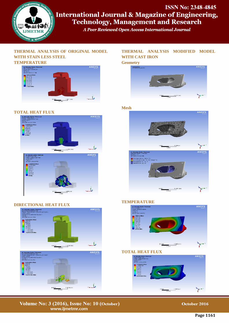
THERMAL ANALYSIS OF ORIGINAL MODEL
WITH STAIN LESS STEEL
TEMPERATURE
TOTAL HEAT FLUX
DIRECTIONAL HEAT FLUX
THERMAL ANALYSIS MODIFIED MODEL
WITH CAST IRON
Geometry
Mesh
TEMPERATURE
TOTAL HEAT FLUX
Page 1162
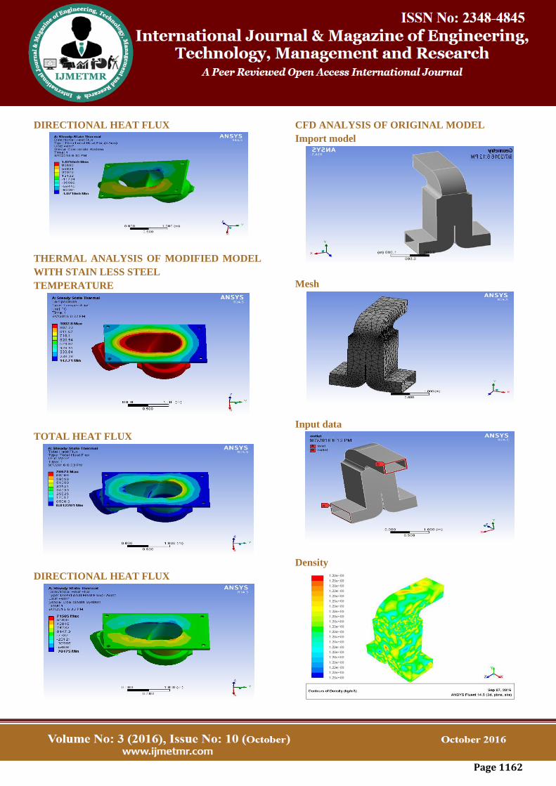
DIRECTIONAL HEAT FLUX
THERMAL ANALYSIS OF MODIFIED MODEL
WITH STAIN LESS STEEL
TEMPERATURE
TOTAL HEAT FLUX
DIRECTIONAL HEAT FLUX
CFD ANALYSIS OF ORIGINAL MODEL
Import model
Mesh
Input data
Density
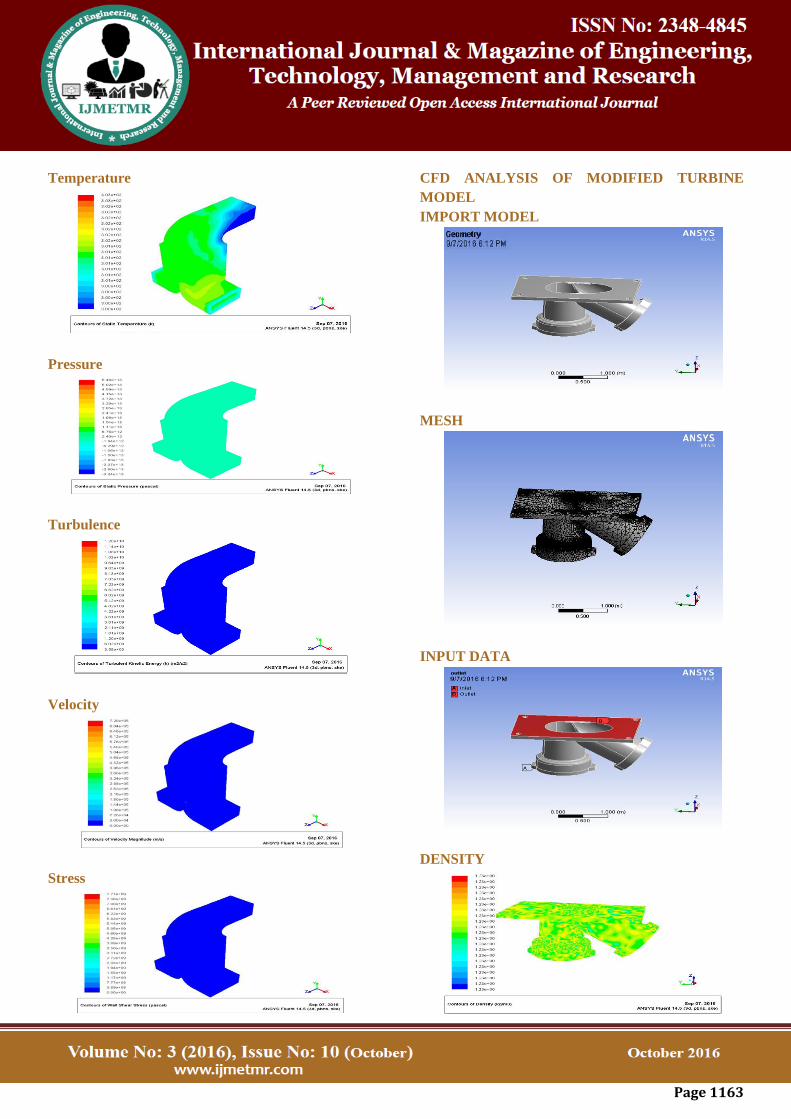
Page 1163
Temperature
Pressure
Turbulence
Velocity
Stress
CFD ANALYSIS OF MODIFIED TURBINE
MODEL
IMPORT MODEL
MESH
INPUT DATA
DENSITY
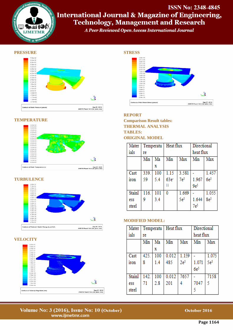
Page 1164
PRESSURE
TEMPERATURE
TURBULENCE
VELOCITY
STRESS
REPORT
Comparison Result tables:
THERMAL ANALYSIS
TABLES:
ORIGINAL MODEL
MODIFIED MODEL:
Page 1165
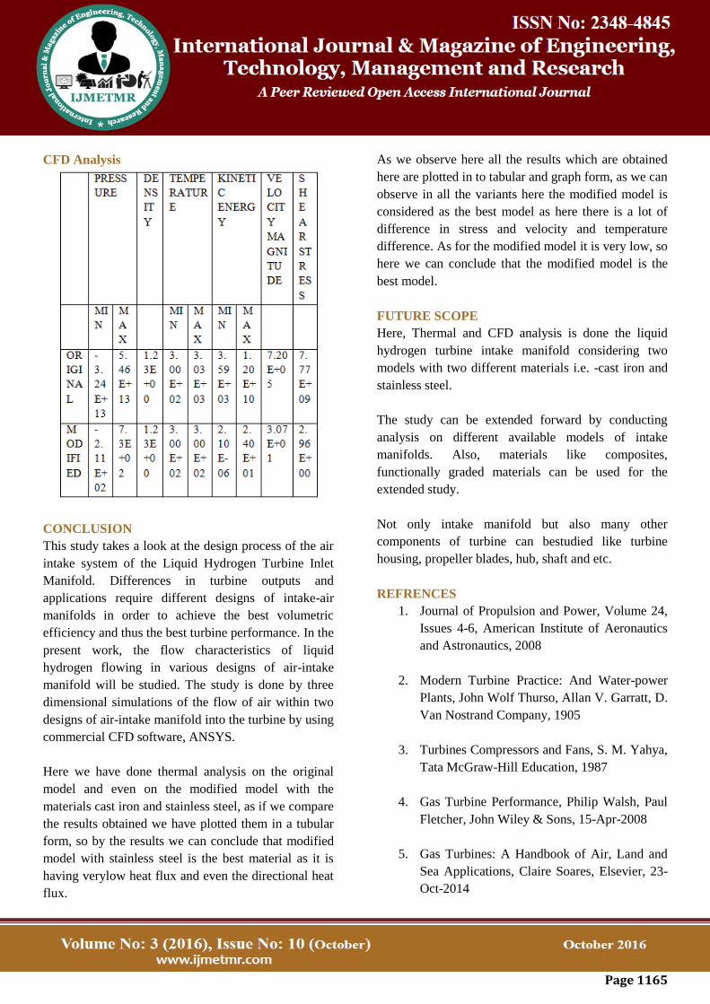
CFD Analysis
CONCLUSION
This study takes a look at the design process of the air
intake system of the Liquid Hydrogen Turbine Inlet
Manifold. Differences in turbine outputs and
applications require different designs of intake-air
manifolds in order to achieve the best volumetric
efficiency and thus the best turbine performance. In the
present work, the flow characteristics of liquid
hydrogen flowing in various designs of air-intake
manifold will be studied. The study is done by three
dimensional simulations of the flow of air within two
designs of air-intake manifold into the turbine by using
commercial CFD software, ANSYS.
Here we have done thermal analysis on the original
model and even on the modified model with the
materials cast iron and stainless steel, as if we compare
the results obtained we have plotted them in a tubular
form, so by the results we can conclude that modified
model with stainless steel is the best material as it is
having verylow heat flux and even the directional heat
flux.
As we observe here all the results which are obtained
here are plotted in to tabular and graph form, as we can
observe in all the variants here the modified model is
considered as the best model as here there is a lot of
difference in stress and velocity and temperature
difference. As for the modified model it is very low, so
here we can conclude that the modified model is the
best model.
FUTURE SCOPE
Here, Thermal and CFD analysis is done the liquid
hydrogen turbine intake manifold considering two
models with two different materials i.e. -cast iron and
stainless steel.
The study can be extended forward by conducting
analysis on different available models of intake
manifolds. Also, materials like composites,
functionally graded materials can be used for the
extended study.
Not only intake manifold but also many other
components of turbine can bestudied like turbine
housing, propeller blades, hub, shaft and etc.
REFRENCES
1. Journal of Propulsion and Power, Volume 24,
Issues 4-6, American Institute of Aeronautics
and Astronautics, 2008
2. Modern Turbine Practice: And Water-power
Plants, John Wolf Thurso, Allan V. Garratt, D.
Van Nostrand Company, 1905
3. Turbines Compressors and Fans, S. M. Yahya,
Tata McGraw-Hill Education, 1987
4. Gas Turbine Performance, Philip Walsh, Paul
Fletcher, John Wiley & Sons, 15-Apr-2008
5. Gas Turbines: A Handbook of Air, Land and
Sea Applications, Claire Soares, Elsevier, 23-
Oct-2014

Page 1166
Author Details
U.Adithya received the B.Tech degree in Mechanical
Engineering from Progressive Engineering College,
JNTU Hyderabad, Telangana, India, in 2013 year, and
perusing M.Tech in Thermal Engineering from Malla
Reddy College of Engineering, JNTU Hyderabad,
Telangana, India.
Sri. B.C. Raghu Kumar Reddy, M.Tech, Assistant
Professor,Malla Reddy College of Engineering, JNTU
Hyderabad, Telangana, India.
Prof.G.Ramesh, M.Tech (Ph.D.) (HOD) Associate
Professor, Malla Reddy College of Engineering, JNTU
Hyderabad, Telangana, India.