Design and Manufacture of a Combined Wheelchair and Tricycle
52
Advanced Composites Design and Manufacture of a Combined Wheelchair and Tricycle Calum Deans 0801992 2010 / 2011 Supervisor: Dr Phil Harrison
Transcript of Design and Manufacture of a Combined Wheelchair and Tricycle

Advanced Composites Design and Manufacture of a Combined
Wheelchair and Tricycle
Calum Deans 0801992
2010 / 2011
Supervisor: Dr Phil Harrison

2
Abstract Focusing on the design of an advanced wheelchair and tricycle, this project investigates
devices available to disabled users and looks at the design of a modern, performance option
aiming to improve the usability of a tricycle by making it no longer necessary to leave the
wheelchair to experience the attributes of a purpose built recumbent tricycle.
The design process is worked through and finite element analysis begun, along with a look
into manufacturing options for both workshop and commercial production.

3
Contents Abstract ............................................................................................................................................ 2
Acknowledgements .......................................................................................................................... 7
1. Introduction .............................................................................................................................. 8
1.1 Objectives ............................................................................................................................. 9
2. Research ................................................................................................................................. 10
2.1 User Group .......................................................................................................................... 10
2.1.1 Categorisation of Injury .......................................................................................................... 10
2.1.2 Potential User Interview .................................................................................................... 11
2.2 Current Products ................................................................................................................. 12
2.2.1 Non-specialised Tricycles ................................................................................................... 12
2.2.2 Disability Specific Tricycles ................................................................................................. 13
3. Design ..................................................................................................................................... 14
3.1 Design Specification ............................................................................................................ 14
3.1.1 Ergonomics: ....................................................................................................................... 14
3.1.2 Features: ............................................................................................................................ 14
3.1.3 Manufacturing: .................................................................................................................. 14
3.1.4 Materials: ........................................................................................................................... 14
3.1.5 Size: .................................................................................................................................... 14
3.1.6 Safety: ................................................................................................................................ 14
3.1.7 Aesthetics:.......................................................................................................................... 14
3.1.8 Cost: ................................................................................................................................... 14
3.2 Methods for Lowering Height ............................................................................................. 15
3.2.1 Spring: ................................................................................................................................ 15
3.2.2 Hydraulic: ........................................................................................................................... 15
3.2.3 Compressed Gas: ............................................................................................................... 15
3.2.4 Winch: ................................................................................................................................ 16
3.3 Concept Development ........................................................................................................ 17
3.3.1 Software ............................................................................................................................. 17
3.3.2 Initial Design....................................................................................................................... 17
3.3.3 Creating the drop motion................................................................................................... 18
3.3.4 Frame Refinement ............................................................................................................. 20
3.3.5 Wheelchair seat ................................................................................................................. 22
3.3.6 Raise/lower procedure ....................................................................................................... 23

4
3.3.7 Complete Chair Render ...................................................................................................... 25
3.4 Design Features ................................................................................................................... 26
3.4.1 Rear end Drop .................................................................................................................... 26
3.4.2 Spring Calculation .............................................................................................................. 27
3.4.3 Front Wheel Lift ................................................................................................................. 29
4. Finite Element Analysis ........................................................................................................... 30
4.1 Understanding Abaqus ........................................................................................................ 30
4.2 Three Point Bend Test ......................................................................................................... 31
4.3 Abaqus Analysis of 3 Point Bend Test ..................................................................................... 33
4.3.1 Material Properties ............................................................................................................ 33
4.3.2 Abaqus Analysis ................................................................................................................. 35
4.4 Abaqus Analysis of Simple Tube .......................................................................................... 38
4.5 Abaqus Analysis of Simplified Frame................................................................................... 39
5. Manufacturing ........................................................................................................................ 41
5.1 Workshop Manufacture ...................................................................................................... 41
5.2 Commercial Manufacture ................................................................................................... 42
6. Conclusions ............................................................................................................................. 43
7. Future Work ............................................................................................................................ 43
References ...................................................................................................................................... 44
Appendices: .................................................................................................................................... 45
A - Spring Calculations ................................................................................................................ 45
B - Halpin-Tsai Twintex ................................................................................................................ 46
C - Animation .............................................................................................................................. 47
D - Convert to Surface in SolidWorks .......................................................................................... 48
E - Exporting from SolidWorks for Abaqus .................................................................................. 50
F - Orthographic Drawing of Wheelchair .................................................................................... 51
G – Exploded Diagram ................................................................................................................. 52

5
Figure 1 – Spinal cord showing classification regions ........................................................................................ 10
Figure 2 – Recumbent Tricycle with 2 rear wheels ............................................................................................ 12
Figure 3 – Berkel Bike Classic ............................................................................................................................ 13
Figure 4 – Berkel Bike Pro ................................................................................................................................. 13
Figure 5 – Torsion Spring .................................................................................................................................. 15
Figure 6 – CO2 Cartridges .................................................................................................................................. 16
Figure 7 – Gas spring from swivel chair ............................................................................................................. 16
Figure 8 - Winch ............................................................................................................................................... 16
Figure 9 – Initial Frame Design .......................................................................................................................... 17
Figure 10 – Short pivot arm raised and lowered ............................................................................................... 18
Figure 11 – Wheel pivot arm swing range ......................................................................................................... 19
Figure 12 – Swing arm extended for manual use .............................................................................................. 19
Figure 13 – Bent swing arm for easier use ........................................................................................................ 20
Figure 14 – Foot rest and mounting clip ............................................................................................................ 20
Figure 15 – Stage 2 Frame with mounts for pivot front wheels ......................................................................... 21
Figure 16 – Final main frame design ................................................................................................................. 21
Figure 17 – Wheelchair adjustable seat ............................................................................................................ 22
Figure 18 – Ratchet adjuster for back rest ........................................................................................................ 22
Figure 19 – Complete wheelchair with front attachment, Front wheel lift ........................................................ 23
Figure 20 – Lowering back end down, showing range of movement ................................................................. 24
Figure 21 – Complete Wheelchair Render ......................................................................................................... 25
Figure 22 – Torsion spring, showing mount for pivot axle ................................................................................. 26
Figure 23 – Torsion spring render ..................................................................................................................... 26
Figure 24 – Front wheel lift mechanism ............................................................................................................ 29
Figure 25 – Twill Weave .................................................................................................................................... 31
Figure 26 – Twintex 3-point bend test, Force vs Displacement.......................................................................... 32
Figure 27 – 3-point bend test, half model ......................................................................................................... 35
Figure 28 – Creating lamina roperties ............................................................................................................... 36
Figure 29 – Creating composite layup ............................................................................................................... 36
Figure 30 – 3-point bend test composite vertical displacement ........................................................................ 37
Figure 31 – 3-point bend test composite vertical resultant force ...................................................................... 37
Figure 32 – 3-point bend test nodes ................................................................................................................. 37
Figure 33 – Cylinder material orientations ........................................................................................................ 38
Figure 34 – Simplification of frame ................................................................................................................... 39
Figure 35 – Section cut showing frame as shell ................................................................................................. 39
Figure 36 – Importing to Abaqus using IGES...................................................................................................... 40
Figure 37 – Importing to Abaqus using ACIS...................................................................................................... 40
Figure 38 – Rotary motor in animation ............................................................................................................. 47
Figure 39 – Recording animation ...................................................................................................................... 47
Figure 40 – Finding surface tools ...................................................................................................................... 48
Figure 41 – Offset surface tool .......................................................................................................................... 48
Figure 42 – Selecting surfaces to offset ............................................................................................................. 49
Figure 43 – Hiding solid body ............................................................................................................................ 49
Figure 44 – Exporting in suitable format ........................................................................................................... 50
Figure 45 – Complete chair orthographic drawing with key dimensions ........................................................... 51
Figure 46 – Complete chair exploded diagram .................................................................................................. 52

6
Table 1 – UTS of wire thicknesses for different materials ................................................................... 28
Table 2 – Composite material properties ............................................................................................ 33
Table 3 – Uni-directional lamina properties........................................................................................ 34
Table 5 – Spring calculation Excel table .............................................................................................. 45
Table 6 – Halpin-Tsai Excel Table ........................................................................................................ 46

7
Acknowledgements
I would like to acknowledge and thank the following people for their contributions and help
throughout the project;
Dr Phil Harrison, my supervisor for his guidance, time and patience throughout the project
Mr. John Davidson for assisting in testing
Dr Sylvie Coupaud for facilitating visits to the Spinal Unit at the Southern General and access
to wheelchairs and tricycles.
Farag Ali (Post grad) for his input and assistance in the manufacturing of composite samples
Weikeong Teng and Niall Morton for cooperation and assistance in testing

8
1. Introduction
This project aims to expand on three previous projects that investigated composite
materials, manufacturing processes in the Lab, and the material properties, comparing
physical specimens to FEA analysis. All the projects were aiming to work towards the
completion of a design for a composite wheelchair with the ability to convert to a
performance orientated tricycle for disabled users without the need to get out of the chair.
The first project climaxed in the design of the front triangle section of a composite full
suspension mountain bike. A bike frame was chosen due to the more simplistic side of the
analysis of a 2-D frame as opposed to a 3-D frame associated with a wheelchair.
The other two projects focused predominantly on the composite material properties and
the comparison between physical testing and simulation using Abaqus Finite Element
package, as well as the manufacturing of the bike frame from the first project.
This project focuses on the design of the wheelchair and method of transforming it from
regular wheelchair into a recumbent tricycle. Additionally the method of manufacture both
in the workshop and on a commercial scale will be considered. The project will aim to
conclude with a basic Finite Element Analysis (FEA) of the chosen wheelchair frame design.

9
1.1 Objectives
The projects objectives began with a simple initial goal to design a composite wheelchair
that converts to a recumbent tricycle, but expanded as the project progressed:
Research user group for combined wheelchair and tricycle
Investigate current tricycle options available for disabled users
Devise a product specification
Design a wheelchair to meet the product specification
Model design using Computer Aided Design (CAD)
Convert design to a format suitable for FEA
Work up to FE analysis of wheelchair frame
10
2. Research
2.1 User Group
2.1.1 Categorisation of Injury When designing a new product it is important to understand the target user group, particularly with
a product designed for a disabled user, as an awareness of abilities and limitations is essential to
come up with a suitable design.
An understanding of different types of disability that would require the use of a wheelchair first
needed to be gained. Basic research was carried out on the area using medical sources on the
internet, as only a level of understanding of what types of disability there are was required and what
limitations they result in.
From the Brain and Spine Foundation website, paralysis is the term given to loss of power to move a
body part, as a result of injury or disease to the nerves supplying the muscles. When used in its
correct context, would imply the complete loss of ability to move and use the effected limbs. There
are two main sub types of paralysis that could lead to the need to use a wheelchair, paraplegia and
tetraplegia. These both come in different levels of severity dependant on the area of the spine that
is injured. Paraplegia refers to paralysis of the lower body, i.e. the legs, and tetraplegia refers to
paralysis of the lower body and the upper body with varying degrees of severity.
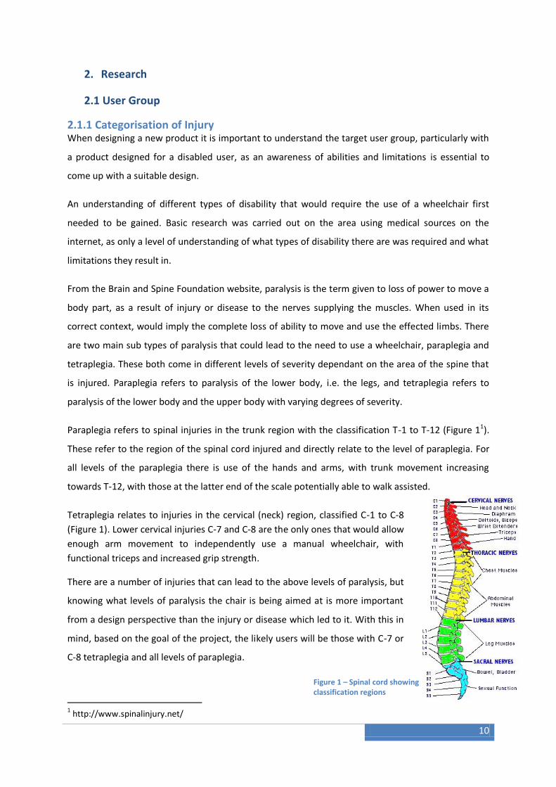
Paraplegia refers to spinal injuries in the trunk region with the classification T-1 to T-12 (Figure 11).
These refer to the region of the spinal cord injured and directly relate to the level of paraplegia. For
all levels of the paraplegia there is use of the hands and arms, with trunk movement increasing
towards T-12, with those at the latter end of the scale potentially able to walk assisted.
Tetraplegia relates to injuries in the cervical (neck) region, classified C-1 to C-8
(Figure 1). Lower cervical injuries C-7 and C-8 are the only ones that would allow
enough arm movement to independently use a manual wheelchair, with
functional triceps and increased grip strength.
There are a number of injuries that can lead to the above levels of paralysis, but
knowing what levels of paralysis the chair is being aimed at is more important
from a design perspective than the injury or disease which led to it. With this in
mind, based on the goal of the project, the likely users will be those with C-7 or
C-8 tetraplegia and all levels of paraplegia.
1 http://www.spinalinjury.net/
Figure 1 – Spinal cord showing classification regions

11
2.1.2 Potential User Interview
As part of the early stages of the project a visit was made to the Southern General Spinal
Unit where a Functional Electronic Stimulation (FES) cyclist goes to use the facilities. FES is
the use of electronic stimulation of the leg muscles to provide enough stimulation to allow
pedalling with the legs for someone who otherwise would have little or no use of their legs.
This is an alternative to the use of a hand crank setup where pedalling is done with the
arms, or both methods can be used together depending on the tricycle setup.
From the interview with the FES cyclist, it was established what the key areas were to focus
on in the design. Independence was found to be one of the most important aspects to the
user, and focus on how this could be aided with careful design consideration would be key.
This includes the ability to manoeuvre the chair while seated in it effectively, being able to
dismantle and lift the chair from out with it such as when getting in and out of a car, and
also the conversion from wheelchair to tricycle whilst still in the chair. Design factors to be
considered to fulfil this included weight minimisation, dismantling and folding the chair,
what adjustments can be made whilst in the chair.
The FES cyclist would use a regular recumbent tricycle (shown in current products sections)
which featured a low riding position compared to a wheelchairs seat height, a more laid
back seating position, and had the wheels spread further apart and the axle of the rear
wheels behind the seating position for increased stability. He also mentioned that the chair
would also have to be suitable for everyday use including obstacles such as doorways
putting limitations on the overall width of the chair. Design factors to be considered here
would be stability, emulating a recumbent riding position, and size limitations.

12
2.2 Current Products
There are a number of different products available on the market at the moment that could
be used be a disabled user for the purpose of a tricycle. The extent to which these are
suitable for purpose varies and there must be an awareness of alternative products to
ensure a unique design with a potential market that is not already being capitalised on is
available.
Current products tended to fall into two categories, designs for fully able users converted or
used as is for a disabled user, or designs specifically for a disabled user.
2.2.1 Non-specialised Tricycles
One category of non-specialised tricycles that could be used was recumbent tricycles. It is
one of these that the FES cyclist at the spinal unit uses. These come in two forms, either
with the 2 wheels at the front or the rear. The benefit of the 2 rear wheel set up (Figure 22) is
an ease of accessibility as far as getting in and out of the seat, and it was this configuration
that is used by the FES cyclist. These designs tend to be very stable due to the wheelbase
(long and wide) and a low recumbent seating position. Disadvantages are that they can be
awkward to get in and out of, with controls in the way and a lower seat position than a
regular wheelchair.
Figure 2 – Recumbent Tricycle with 2 rear wheels
2 http://www.bicycleman.com/recumbents/trikes/hase/hase-KettWiesel-recumbent-trikes.htm
13
2.2.2 Disability Specific Tricycles
Berkel is a company which specialise in disability specific tricycles, with a range of products
aiming to cater for a variety of needs.
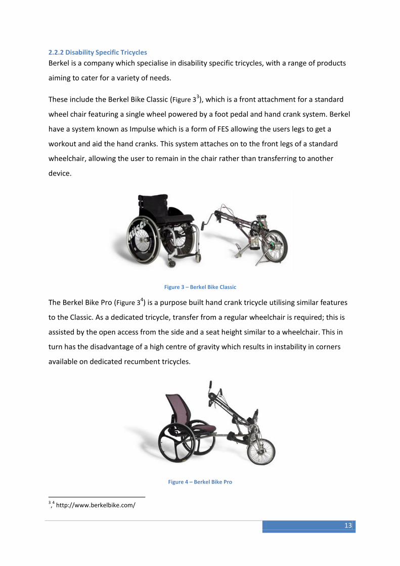
These include the Berkel Bike Classic (Figure 33), which is a front attachment for a standard
wheel chair featuring a single wheel powered by a foot pedal and hand crank system. Berkel
have a system known as Impulse which is a form of FES allowing the users legs to get a
workout and aid the hand cranks. This system attaches on to the front legs of a standard
wheelchair, allowing the user to remain in the chair rather than transferring to another
device.
Figure 3 – Berkel Bike Classic
The Berkel Bike Pro (Figure 34) is a purpose built hand crank tricycle utilising similar features
to the Classic. As a dedicated tricycle, transfer from a regular wheelchair is required; this is
assisted by the open access from the side and a seat height similar to a wheelchair. This in
turn has the disadvantage of a high centre of gravity which results in instability in corners
available on dedicated recumbent tricycles.
Figure 4 – Berkel Bike Pro
3,4 http://www.berkelbike.com/

14
3. Design
3.1 Design Specification Using the information gathered in the research a design specification was established to give a guide
in the generation of ideas and to keep the design focused. Some aspects of the design were to be
more important than others and would get greater focus. The design aims to provide a performance
wheelchair that can easily be converted to a tricycle while remaining in the wheelchair by means of a
front attachment. The wheelchair should also convert into a more suitable setup for use as a tricycle
such as seen in recumbent tricycles. The wheelchair should be suitable, in normal configuration, for
everyday use.
3.1.1 Ergonomics: The aspects of ergonomics that need consideration are physiological and
anthropometrics. The physiological restrictions on a disabled user will affect their ability to use the
chair and any devices associated with it. Anthropometrics will need to be considered to ensure the
chair is a suitable size for most users, with suitable adjustments incorporated to allow for different
shapes and sizes of users.
3.1.2 Features: Ability to drop chair height while seated. Attach a front pedal unit such as is
available from Berkel. Adjust seat back to give a position similar to a recumbent tricycle.
3.1.3 Manufacturing: Manufacturing processes considered in both workshop and for commercial
scale. What options are available and which are most suitable.
3.1.4 Materials: As a performance orientated project with a focus on composite materials due to
their good strength to weight ratios and ability to tailor their make-up to optimise performance,
these should be should where appropriate in the design.
3.1.5 Size: The overall wheelchair size will be constrained by the environmental aspects such as
doorway widths, and must be able to fold/dismantle the chair to fit into a car.
3.1.6 Safety: British Standards relating to wheel chairs will need to be considered and accounted
for. The chair must be able to cope with the static load of the user and also any repeated loadings
from its everyday use.
3.1.7 Aesthetics: The aesthetics are not to be a main focus point, but the chair should look
appropriate and be appealing.
3.1.8 Cost: Costing to be carried out for workshop prototype and commercial production (material
costs) if possible. Use of off the shelf components where suitable.

15
3.2 Methods for Lowering Height One of the key features to be incorporated into the design was a method to drop the wheelchair
seating position down to one similar to a recumbent tricycle. This was to be done such that the user
would be able to lower and raise themselves while in the chair.
In order to make this possible, there needs to be a device installed in the chair to provide assistance
in the raising of the seat position. This will need to either be done by storing energy on the lowering
process, or by providing additional energy when it comes to raising the seating position.
A number of possible devices were considered for this task and their advantages and disadvantages
considered:
3.2.1 Spring: (Figure 55) As spring is a simple device that can will store energy in a variety of ways
such as tension, compression and torsion, depending on the type of spring and the way in which it is
loaded. By using a spring in its unloaded state when the seat is in the highest position, when lowered
down it will store energy which can be later used to aid the raising procedure. If a spring is to be
used, a mechanism will need to be devised to make the most of the spring.
Figure 5 – Torsion Spring
3.2.2 Hydraulic: The use of hydraulics would be effective in raising and lowering the seating
position, although the associated equipment required to make it work would over complicate the
wheelchair design, as well as taking up valuable space and weight.
3.2.3 Compressed Gas: (Figure 66) This method involves using a compressed gas such as CO2 as
found in inflatable lifejackets, and tyre inflators. This could be used in conjunction with a gas spring
(Figure 77) similar to what is used in a swivel chair, with the gas cartridges refilling the cylinder and
extending the gas spring without having to remove weight as you would have to with a swivel chair.
With this option, each cartridge would have a limited number of uses requiring regular replacement.
5 http://www.engineeringtalk.com/guides/torsion-spring.html
6 http://www.klr650.com/CO2%20Tire%20Pump.htm 7 http://www.industrystock.com/html/Swivel%20chair%20gas%20springs/product-result-uk-174187-0.html

16
Figure 6 – CO2 Cartridges
Figure 7 – Gas spring from swivel chair
3.2.4 Winch: (Figure 88) Using a winch to raise and lower the seating position is an obvious option
and would be the simplest to carry out. The issue with using a winch is mainly its size and weight,
two aspects that would be detrimental to the performance of the wheelchair.
Figure 8 - Winch
From the above options for the raising and lowering the seating position, the option of a form of
spring powered mechanism was chosen as most suitable. This was due to the simplicity it would
bring to the design, along with reliability. From the various types of springs and ways of
implementing them, a torsion spring system was considered the best option and the reasons for this
will be considered in more detail in the mechanisms section.
8 http://www.boatwinch.org/boat-lift-winch/

17
3.3 Concept Development The wheelchair design was developed with focus on the key issues addressed in the design
specification, taking a basic, minimalist frame as a starting point and developing the key features to
make it a unique and innovative design around it.
3.3.1 Software
The wheelchair design was done using SolidWorks Computer Aided Design (CAD) software.
SolidWorks is a powerful CAD package allowing easy, but concise models to be created in such a way
that the user is encouraged to properly constrain their creations ensuring there are minimal issues
later in the design process. It allows complete assemblies to be created with options to create
animations, useful when demonstrating how a product functions. Further, technical drawings are
quick and easy to create from parts and assemblies.
3.3.2 Initial Design
The frame was initially designed as one piece, incorporation a foot rest, mounts for the front wheels
and mounting points for the seat (Figure 9). The main frame sections were based around simple
cylinders with a view ahead to the manufacturing processes and keeping the design as simple as
possible. The basic frame was used to start building up the mechanism for lowering the seating
position, the amount of drop to be seen and any interference between components to be seen.
Figure 9 – Initial Frame Design
The first part of the mechanism to devise is the motion of the drop. The first goal was to provide a
height drop, but secondly from looking at the recumbent tricycles, the ability to extend the wheel
base for stability would also be desirable. To achieve a change in both height and length
simultaneously the ideal choice was a swing arm whereby the wheels are brought from directly
below the frame to behind and closer to the frame.

18
3.3.3 Creating the drop motion
Initially the swing arms were made quite short to understand the motion, and before the height
drop aimed for was determined. A small level of drop can be seen in the frame in Figure 10, but not
to the extent that would make an effective difference.
Figure 10 – Short pivot arm raised and lowered
To gain a greater change in height, the length of the swing arms was increased and using a CAD
drawing (Figure 11), the drop height of the seat could be determined along with the angle of motion
the arm will have to swing through. The CAD drawing created shows the position of the rear wheel
at various points in the swing centred around the arm pivot point on the frame. The level of drop
was to provide a new seat height similar to that of a recumbent tricycle as well as providing an equal
amount of movement horizontally as vertically increasing wheelbase length by a similar amount to
the height decrease.
A swing angle of 85o from 5o off the vertical gives a drop of just over 160mm, providing a sufficient
change in height.

19
Figure 11 – Wheel pivot arm swing range
With the movement for the height drop established, the method for actuating it had to be designed.
The use of torsion springs had already been decided upon, but alone would not be enough to
provide the raising motion. The proposed user is expected to have a level of upper body and arm
strength which could be used to aid in the motion.
By extending the swing arms out the opposite direction, they can act as levers from which the user
can contribute to the motion. The length of the arms had to be long enough to bring the handles
clear of the wheels. The greater length also provides a greater amount of leverage. Shown in Figure
12 below:
Figure 12 – Swing arm extended for manual use

20
To improve the position of the handles for the swing arms, the lever arms were bent to provide a
more appropriate angle for use, providing a movement from full extended arms to approximately
90o as opposed to bring the levers right under the shoulders where optimal strength is not available
(Figure 13).
Figure 13 – Bent swing arm for easier use
3.3.4 Frame Refinement
As can be seen from the development of the swing arm, the frame has changed in several respects.
The most obvious change is that the foot rest has been made a separate component; this was to
allow it to be positioned optimally for different leg lengths using a simple hole and clip method with
different position holes on the main frame. The footrest and clip can be seen in Figure 14.
Figure 14 – Foot rest and mounting clip
21
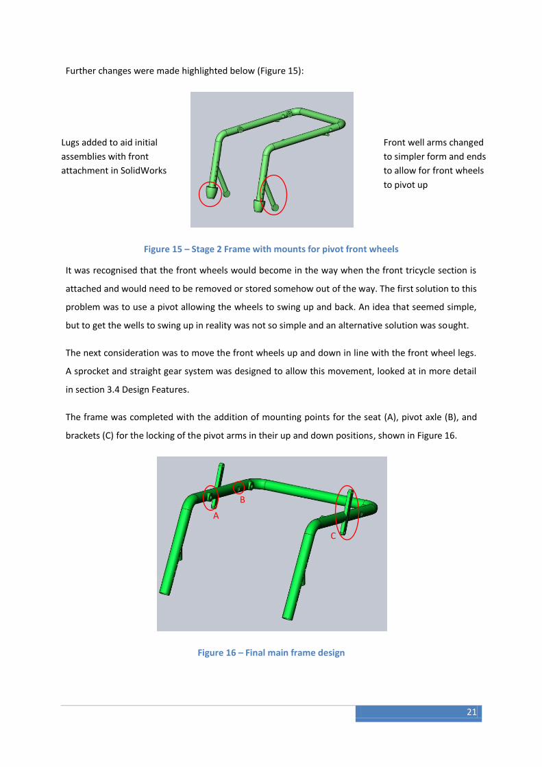
Further changes were made highlighted below (Figure 15):
Figure 15 – Stage 2 Frame with mounts for pivot front wheels
It was recognised that the front wheels would become in the way when the front tricycle section is
attached and would need to be removed or stored somehow out of the way. The first solution to this
problem was to use a pivot allowing the wheels to swing up and back. An idea that seemed simple,
but to get the wells to swing up in reality was not so simple and an alternative solution was sought.
The next consideration was to move the front wheels up and down in line with the front wheel legs.
A sprocket and straight gear system was designed to allow this movement, looked at in more detail
in section 3.4 Design Features.
The frame was completed with the addition of mounting points for the seat (A), pivot axle (B), and
brackets (C) for the locking of the pivot arms in their up and down positions, shown in Figure 16.
Figure 16 – Final main frame design
Lugs added to aid initial
assemblies with front
attachment in SolidWorks
Front well arms changed
to simpler form and ends
to allow for front wheels
to pivot up
A
B
C
22
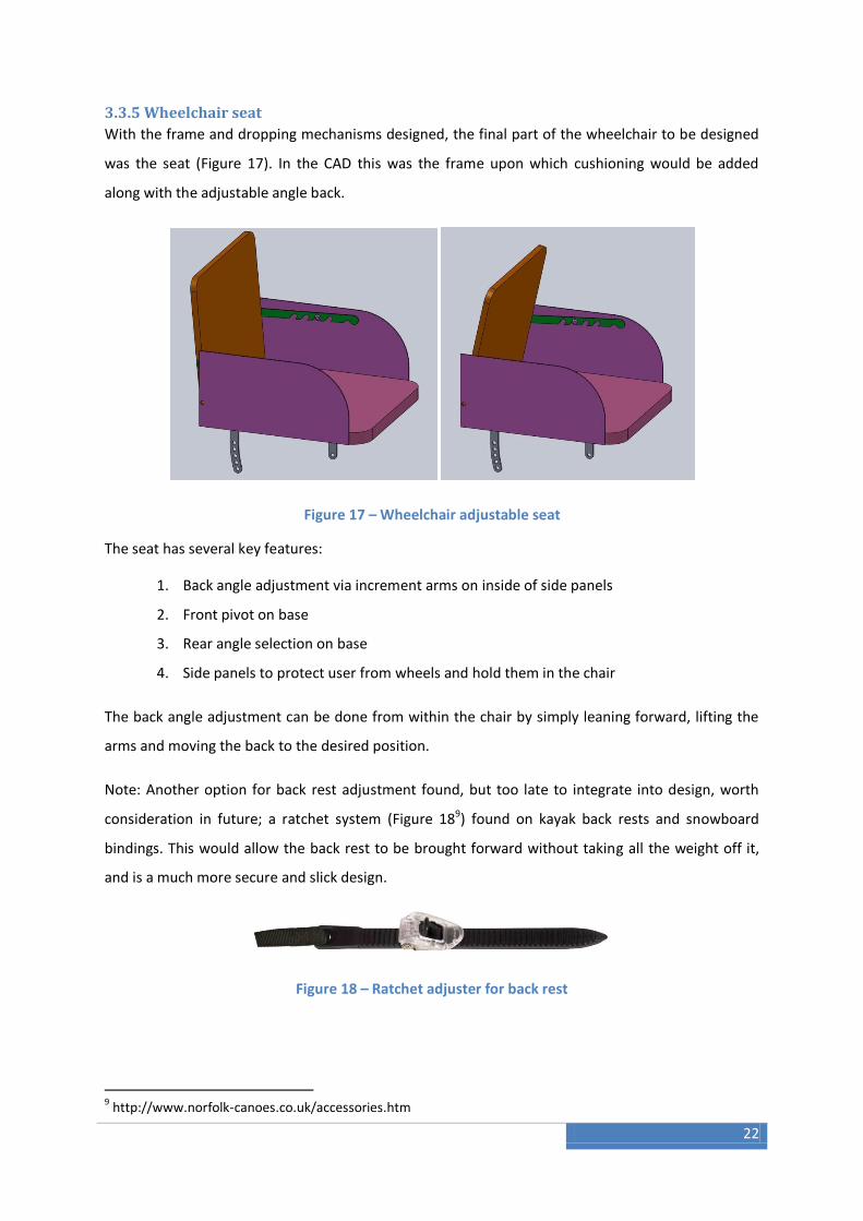
3.3.5 Wheelchair seat
With the frame and dropping mechanisms designed, the final part of the wheelchair to be designed
was the seat (Figure 17). In the CAD this was the frame upon which cushioning would be added
along with the adjustable angle back.
Figure 17 – Wheelchair adjustable seat
The seat has several key features:
1. Back angle adjustment via increment arms on inside of side panels
2. Front pivot on base
3. Rear angle selection on base
4. Side panels to protect user from wheels and hold them in the chair
The back angle adjustment can be done from within the chair by simply leaning forward, lifting the
arms and moving the back to the desired position.
Note: Another option for back rest adjustment found, but too late to integrate into design, worth
consideration in future; a ratchet system (Figure 189) found on kayak back rests and snowboard
bindings. This would allow the back rest to be brought forward without taking all the weight off it,
and is a much more secure and slick design.
Figure 18 – Ratchet adjuster for back rest
9 http://www.norfolk-canoes.co.uk/accessories.htm

23
The seat base angle relative to the frame can be adjusted out with the chair using the angle selection
arm at the rear of the base, this is an option that will be chosen by the user as their optimal and left,
with minor angle adjustments possible of the overall chair using the front wheel height.
3.3.6 Raise/lower procedure
In order to give an idea of what the chair would be like in tricycle mode, a simple front
section was designed with just a wheel and attachments to the main frame, as at this stage
the intention would be to just use a standard Berkel front end.
With the front end attached, the motions of the chair can be seen along with the steps for
conversion to tricycle:
Step 1: Attach front section, Figure 19
Step 2: Lift front wheels (method shown in 3.4 Design Features), Figure 19
Figure 19 – Complete wheelchair with front attachment, Front wheel lift

24
Step 3: Lower rear wheels using lever arms, Figure 20
Figure 20 – Lowering back end down, showing range of movement

25
3.3.7 Complete Chair Render
The final chair was rendered in its assembled state to give an impression of how it would
look manufacture in predominantly carbon composite, shown in Figure 21.
Figure 21 – Complete Wheelchair Render

26
3.4 Design Features
3.4.1 Rear end Drop
This is the most standout feature of the design, and so it is important to get it right. The basics of the
design have already been described in section 3.3, and so this section will go into more detail of how
it works.
Figure 22 – Torsion spring, showing mount for pivot axle
It was decided to use two torsion springs to create a balanced force between both sides of the chair.
These are mounted on an axle that passes through the pivot point for the swing arms on both sides
of the chair and through the frame as well. The springs are mounted on the inside of the frame,
attaching to the axle via a metal ring with grub screws to hold its position. The springs are then fixed
directly into the side of the frame, with opposite direction springs so the rotation that increases
torsion is the same for both. One of the spring is shown mounted in Figure 22 and rendered in Figure
23.
Figure 23 – Torsion spring render

27
3.4.2 Spring Calculation
The correct size of the spring was calculated using an iterative process starting with the load the
spring must take, a rough diameter and the spring material. From this the diameter, wire diameter,
and number of coils was calculated. The springs were assumed to take 60% of the load, with the user
having to account for the other 40%, this was based on a user mass of 80kg, although due to the
design of the spring set up, the spring could be preloaded to account for a larger range of masses.
This is done using the attachment for the spring to the pivot axes, rotating the fitting and fixing in
place using the grub screws.
The size of spring required was calculated using an iterative process based around taking an
estimated initial spring diameter and wire diameter, and then knowing the force it must apply and
the range of movement, the spring can be selected.
The range of movement, θ, is the angle the swing arm pivots through in radians, 1.48rad
Two springs, each giving a force of 235.44N based on taking 60% of effort
Initial spring diameter of 35mm, initial wire diameter of 3mm
Material selected, ASTM A228, Music Wire
From these initial specifications, through iteration, a suitably sized spring was found with yield
strength in the conditions greater than the maximum stress the spring will endure to ensure no
failure would occur. The Ultimate Tensile Strength (UTS) for the initial specification was taken from
Table 110.
10 Harrison, P (2010), Lecture notes, Design of Springs_Torsion

28
Table 1 – UTS of wire thicknesses for different materials
The yield strength is then found using the value for yield stress relating to chosen material. The
spring wire diameter is then updated using the equation for maximum stress:
The ‘d’ value found is then rounded up to the nearest wire diameter available to ensure it is over
specified rather than under specified. A new UTS is found from the table, to find the new yield
strength. It is checked that this value is greater than max.
The number of coils, unloaded length and loaded length of the spring, and minimum inside diameter
were then calculated:
Spring Diameter = 35mm
Spring wire thickness = 3.5mm
Number of coils, N = 29.5
Unloaded length = 107mm
Loaded length = 112mm
Minimum inside diameter = 30mm
3max
32
d
FrKi

29
3.4.3 Front Wheel Lift
The front wheel lift was an issue that became apparent as the design progressed, and went
through several iterations, described in section 3.3. The final chosen design was a vertical lift
system allowing each front wheel to be moved independently.
Using a gear and a notched cylinder, the front wheel can be raised by hand from within the
chair. See Figure 24
Step 1: Pull winged handle out sideways
Step 2: Rotate to raise or lower leg
Step 3: Push handle back in to lock front wheel in place
Using ball bearings sprung on the inside of the handle to provide resistance to hold it in
place when pushed in or pulled out and a small lip to prevent it being pulled off.
By making small adjustments with the front wheel height without the front attachment,
minor adjustments can be made to the overall wheelchair angle.
The front wheel lift system provides a maximum range of 65mm, enough to lift the wheels
clear of the ground with the seat in the lowered position and front pedal section attached.
Figure 24 – Front wheel lift mechanism
30
4. Finite Element Analysis
Finite Element Analysis (FEA) was the next stage of the project, although most of the time had been
spent on completing the design. FEA was the obvious next step, as with a completed design it is
important to understand what it will endure during its use. By using FEA any problems with the
design, such as weak points, unwanted flexing, as well as potential areas for problems during
manufacture can be sought out. The design can then be altered and analysed again, before costly
time and resources are put to manufacturing what could potentially be a product containing many
problems.
The FEA package used was Abaqus/CAE Student Edition 6.9. This version has limitations on the
maximum number of nodes (1000), but this was in excess of what would be required and provided
all the components required for the analysis.
4.1 Understanding Abaqus
Before analysis could be started on the wheelchair, experience with the software had to be gained
as with SolidWorks. This was done be using the Abaqus supplied tutorials that built the analysis
process up in stages. Knowledge gained from working through the tutorials along support materials
were used to complete the analysis.
31
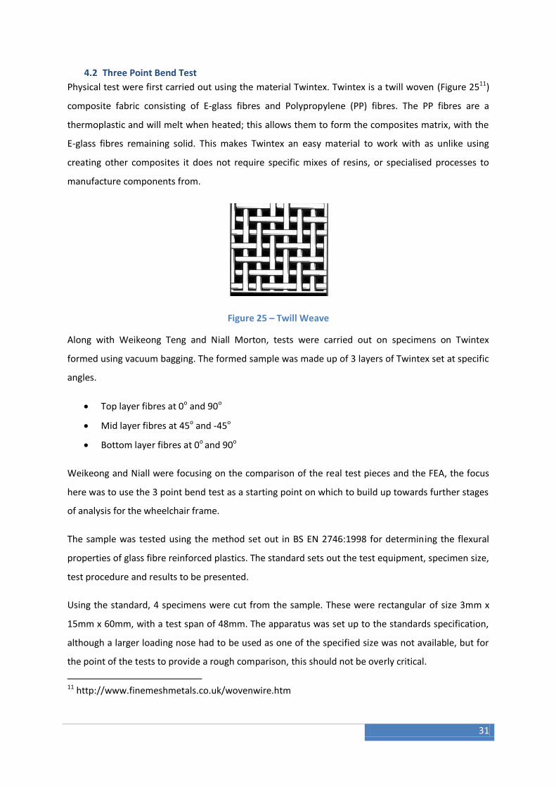
4.2 Three Point Bend Test
Physical test were first carried out using the material Twintex. Twintex is a twill woven (Figure 2511)
composite fabric consisting of E-glass fibres and Polypropylene (PP) fibres. The PP fibres are a
thermoplastic and will melt when heated; this allows them to form the composites matrix, with the
E-glass fibres remaining solid. This makes Twintex an easy material to work with as unlike using
creating other composites it does not require specific mixes of resins, or specialised processes to
manufacture components from.
Figure 25 – Twill Weave
Along with Weikeong Teng and Niall Morton, tests were carried out on specimens on Twintex
formed using vacuum bagging. The formed sample was made up of 3 layers of Twintex set at specific
angles.
Top layer fibres at 0o and 90o
Mid layer fibres at 45o and -45o
Bottom layer fibres at 0o and 90o
Weikeong and Niall were focusing on the comparison of the real test pieces and the FEA, the focus
here was to use the 3 point bend test as a starting point on which to build up towards further stages
of analysis for the wheelchair frame.
The sample was tested using the method set out in BS EN 2746:1998 for determining the flexural
properties of glass fibre reinforced plastics. The standard sets out the test equipment, specimen size,
test procedure and results to be presented.
Using the standard, 4 specimens were cut from the sample. These were rectangular of size 3mm x
15mm x 60mm, with a test span of 48mm. The apparatus was set up to the standards specification,
although a larger loading nose had to be used as one of the specified size was not available, but for
the point of the tests to provide a rough comparison, this should not be overly critical.
11 http://www.finemeshmetals.co.uk/wovenwire.htm
32
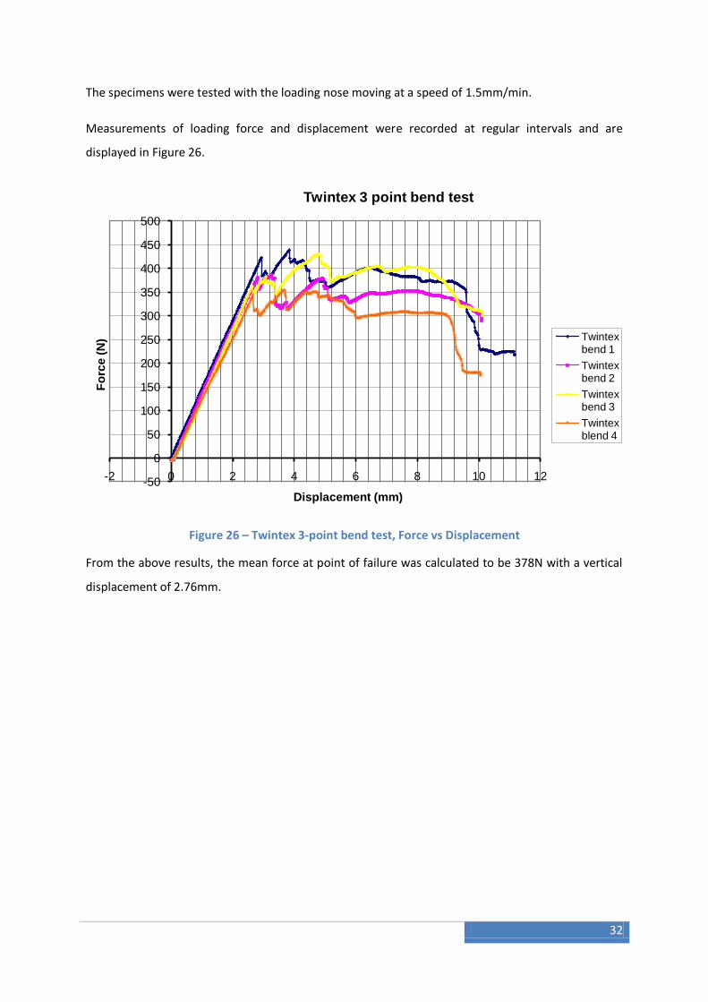
The specimens were tested with the loading nose moving at a speed of 1.5mm/min.
Measurements of loading force and displacement were recorded at regular intervals and are
displayed in Figure 26.
Figure 26 – Twintex 3-point bend test, Force vs Displacement
From the above results, the mean force at point of failure was calculated to be 378N with a vertical
displacement of 2.76mm.
-50
0
50
100
150
200
250
300
350
400
450
500
-2 0 2 4 6 8 10 12
Fo
rce
(N
)
Displacement (mm)
Twintex 3 point bend test
Twintex bend 1
Twintex bend 2
Twintex bend 3
Twintex blend 4

33
4.3 Abaqus Analysis of 3 Point Bend Test
4.3.1 Material Properties
In order to get a useful comparison between the physical tests and the FEA, the material properties
of Twintex need to be known. These are not readily available to the level required for FEA, but the
material make up of Twintex is known with 35% E-glass12 to 65% PP.
The approximation is made that each layer is uni-directional, and then using Halpin-Tsai, an
empirical method of expressing a composites properties based upon its constituent matrix and fibre
materials including the ratio and their geometry.
The equations are used to find the composite’s modulus, M (i.e. E2, G12, or v23) from the fibre’s
modulus, Mf, and matrix’s modulus, Mm. Where ‘f’ is the fibre volume fraction and relates to the
geometry of the fibres.
Based on Halpin-Tsai and the following properties E-glass (fibre)13 and PP (Matrix)14:
Table 2 – Composite material properties
Volume fraction of fibres, f 0.35
Young's modulus fibres, Ef 7.24E+10 Pa
Young's modulus matrix, Em 1.12E+09 Pa
Poisson's ratio fibres, vf 0.2
Poisson's ration matrix, vm 0.3
Shear Modulus of Fibres, Gf 3.00E+10 Pa
Shear Modulus of Matrix, Gm 5.38E+08 Pa
12
http://www.ocvreinforcements.com/pdf/products/Twintex_TPP_ww_06_2008_Rev5.pdf 13http://www.matweb.com/search/DataSheet.aspx?MatGUID=d9c18047c49147a2a7c0b0bb1743e812&ckck=1 14 http://www.matweb.com/search/DataSheet.aspx?MatGUID=1202140c34e8443bbf273862e24c5f0e&ckck=1

34
The material properties for a uni-directional lamina layer of E-glass and PP is:
Table 3 – Uni-directional lamina properties
E11 2.61E+10 Pa
E22 2.81E+09 Pa
G12 1.09E+09 Pa
G13 1.09E+09 Pa
G23 1.08E+09 Pa
v12 0.265
These properties were then used in the Abaqus analysis to represent the properties of Twintex.

35
4.3.2 Abaqus Analysis
The 3 point bend test was then created in Abaqus. This was done using 3-D shell elements as this
would allow the material to be easily assigned and varied without having to re-draw the model,
additionally shell elements would later need to be used for the analysis of the wheelchair frame.
The model was created as half the 3-point bend test done in the lab, due to the symmetry in the
process. This was to simplify the model and speed up the analysis process (Figure 27).
Figure 27 – 3-point bend test, half model
The model was initially specified as steel, an isotropic material, to test the analysis by keeping the
process as simple as possible. The material properties were an elastic material with Young’s modulus
of 200GPa and Poisson’s ratio 0.3.
This provided a successful analysis, and so the material was changed to a composite similar to that
used in the physical test.
The basic composite layup tool available in Abaqus does not allow for woven materials such as the
Twintex used in the physical test, therefore the material was simplified to a non-woven layup, but
with the layers reflecting the angles of the woven layup. The material was selected as a lamina and
given the properties calculated using Halpin-Tsai (Figure 28).

36
Figure 28 – Creating lamina roperties
Figure 29 shows the layup used in the Abaqus analysis:
Figure 29 – Creating composite layup
The analysis was run using Boundary Conditions to change the displacement of the centre of the
part, while constraining the supported point as it would have been in the physical test. The
displacement of the edge representing the mid-span of the specimen was set to 2.76mm, the mean
displacement at failure found in the physical tests, with the intention to find the force along the mid-
span at this displacement to validate the results.
The model was seeded such that each square in the mesh would be 3mm by 3mm. This was based
on the investigation by Weikeong15 into the effect of the mesh density with this determined to be
the best balance between accuracy and efficiency.
Figure 30 shows the result of the analysis, showing the contours of the displacement in the 3-
direction (vertical displacement).
15 Weikeong Teng, Comparison of Composite material with Finite Element Analysis 2010

37
Figure 30 – 3-point bend test composite vertical displacement
As can be seen in the figure above, the specimen deflects as it did in the physical test, although not
to the point of breaking, this is where the physical test was useful, knowing the displacement at
which failure occurred, allows it to be used in the FEA as the end point for the analysis as it is known
up to that point that the specimen behaves linearly.
The resultant forces were also of interest as they can be compared directly to the physical test.
Figure 31 shows the resultant forces in the 3 (vertical direction).
Figure 31 – 3-point bend test composite vertical resultant force
The result forces at the nodal points were output to a report. By summing the resultant forces at
each of the nodes (Figure 32) along the edge representing the mid-point of the test specimen, it was
found that the total resultant force was 359.9N. This value sits within the range of values measured
at the point of failure of the test specimen confirming the accuracy of the FEA simulation.
Figure 32 – 3-point bend test nodes

38
4.4 Abaqus Analysis of Simple Tube
A simple tube was created in SolidWorks and imported into Abaqus (method described in
Section 4.4). The material orientation for a flat plate is simple as the surfaces face one
direction, but for a cylinder with a curved surface, the normal to the surface varies. It is for
this reason that the material orientations need to be defined separately.
The cylinder when imported was segmented into two halves. The aim when creating the
material orientations was to have the normals at all points perpendicular to the surface of
the cylinder outwards. The 2-directions all pointing the same direction along the length of
the cylinder and the 1-direction pointing at a tangent to the cylinder surface all in the same
direction of rotation around the cylinder.
When plotting the material orientations on the cylinder, Abaqus necessitated that the
orientation be plotted separately for each half of the cylinder. By assigning datum axis
appropriately all the normals were plotted perpendicular to the cylinder, 2-axis all ran along
the tube length, and 1-axis at a tangent to the surface. Despite this, the orientations on each
half for 1- and 2-axis were reversed. Figure 33 shows the material orientations on the
cylinder.
Figure 33 – Cylinder material orientations
The orientations could create problems during analysis; unfortunately there was not time to
proceed further with the Abaqus analysis.

39
4.5 Abaqus Analysis of Simplified Frame To carry out a direct analysis on the full wheelchair frame would not be easy and could result in
many errors along the way. To begin with an analysis of a simpler frame would be more likely to lead
to success and make spotting errors or possible problems a lot easier. To this end the frame was
simplified in Abaqus first and converted to a shell to make applying material properties to it easier.
The foot rest was attached to the main frame and detailed components removed before the solid
object was changed to a surface model (Figure 34).
Figure 34 – Simplification of frame
Figure 35 – Section cut showing frame as shell
To analysis the frame in Abaqus, it must be imported from SolidWorks. To do this the CAD model
must be saved as an appropriate file format recognised by abaqus. Two options are available, IGES
file and ACIS file.
IGES stands for Initial Graphics Exchange Specification, and is designed to be a neutral format for
transferring a design between dissimilar software packages (http://ts.nist.gov/standards/iges/).

40
ACIS is a 3D modeller based on object orientated C++ architecture and is designed as an open format
particularly suited to applications that require flexibility so that varies modelling features can be
used. This makes it a useful format for exporting and importing between different software packages
using 3-D modelling.
Figure 36 shows the simplified frame imported into Abaqus using IGES format. The format can be
seen to displays issues with complex geometries such as tight angles and interfaces between
dissimilar shapes in the model. This could pose issues when later analysis is run.
Figure 36 – Importing to Abaqus using IGES
Importing into Abaqus using ACIS format (Figure 37) raises no issues, and so would likely make the
more appropriate basis for further analysis in Abaqus.
Figure 37 – Importing to Abaqus using ACIS
41
5. Manufacturing Manufacturing is a key area to investigate for any product. For the wheelchair manufacturing must
be looked at in two contexts; workshop manufacture and commercial manufacture. The workshop
manufacture will focus on limited production and prototyping, whereas the commercial
manufacturing section will investigate the most viable options for producing the wheelchairs for
sale.
5.1 Workshop Manufacture Workshop manufacturing has to be suited to the processes and machinery already available in the
University. The bike frame from Alan Easdale’s project uses two male moulds, each half the bike
frame. This allows the frame to be built in two halves by layering the composite on the individual
moulds and then using vacuum bagging or vacuum infusion to cure the composite depending on the
material chosen. The two halves are then trimmed and fixed together with the aid of skeleton
pieces. This works well with a bike frame, due to the 2-D nature of it, but is unlikely to translate well
to the 3-D form of the wheelchair frame. This is due to the difficulty of splitting the frame into parts
that can be moulded with a single piece mould and easily release it after curing. Based on the
process for creating the bike moulds, this would be a time consuming process milling the board to
the mould shape, followed by the priming of the surface before it can be used.
One manufacturing option for the workshop would be to use a single use process similar to the idea
of investment casting where a single use mould is made and destroyed after use when releasing the
casting. For composite forming a male mould could be made from polystyrene, most likely in
multiple pieces to simplify the process of creating the moulds and to allow smaller machinery to be
used to create the moulds. The composite can then be layered around the assembled mould. Due to
the size and shape of the mould, vacuum bagging or infusion would not be easy to carry out, and a
wet layup followed by a tight wrap would be easiest to mould the frame.
Alternatively, if a reusable process is desired, recommendation would be to split the frame into
multiple parts. There are a number of long straight tube sections to the frame, these could be
moulded around a metal pipe, either individually, or as one long piece and cut to the individual
lengths. The other parts and then much smaller than the whole frame and could be produced in a
two-part mould similar to the bike mould, with smaller diameter extensions to either end to allow
them to be inserted into the tube sections. The whole frame once slotted together could then be
wrapped in additional layers of composite material to ensure extra strength. Each of these options
would have different resulting properties and potential weak spots, and this would have to be
considered with any further simulation as to which manufacturing process is chosen.

42
5.2 Commercial Manufacture
Composite manufacturing has progressed significantly of the recent years, becoming more
accessible in the commercial market what was once the reserve of the aerospace industry. For the
manufacturing of a wheelchair frame, the bicycle industry offers some viable options.
For producing a one-piece, high quality frame there is one stand out process. This involves using an
air-bladder. The air-bladder is custom made to the shape of the frame with no stand out seems. The
layup is then made over the inflated air bladder before being put in a female mould to cure. Once
cured, the mould is released, and the bladder is deflated and removed from the inside of the frame,
ready to be re-used.
This produces an accurate frame, with a high quality internal and external finish, ensuring the
thickness at key points are as intended, and giving a sleek one-piece frame.
Giant Bicycles are using their own version of this process for their top end carbon fibre road and
mountain bike frames, with great result.16
This process would involve a high set-up cost due to the specialised equipment, but should a regular
production be required, in the long term would be a more viable option than those suggested for
workshop production.
16 http://archive.giant-bicycles.com/uk/050.000.000/050.005.000.asp

43
6. Conclusions
During the course of the project, most objectives were achieved, with a completed design
for the wheelchair and a suitable method for converting it into a tricycle that is both modern
and simple. Work has been started on the Finite Element Analysis, and this combined with
work from previous projects should allow a full analysis to be conducted in few steps.
Further, suggestions have been proposed for the most suitable manufacturing processes
and should allow a prototype to be produced in the workshop from which comparison can
be made between FEA and physical testing.
7. Future Work
This project is now at the stage where it is ready to start producing prototypes. The next
steps would be:
Decide on the workshop production process and construct a prototype
Continue Abaqus analysis with frame, utilising work of Weikeong Teng and Niall
Morton
Run further practical tests, particularly with cylinder sections to build up a model of
how these sections might behave in the frame
Consider layup orientations and how to optimise them on the wheelchair frame

44
References [1] Spinal Injury Information, http://www.spinalinjury.net/ [Accessed 21 April 2011]
[2] Recumbent Tricycle picture, http://www.bicycleman.com/recumbents/trikes/hase/hase-
KettWiesel-recumbent-trikes.htm
[3,4] Information on Berkel Bikes and images, www.berkelbike.com
[5] Torsion spring image, http://www.engineeringtalk.com/guides/torsion-spring.html
[6] CO2Cartridge Image, http://www.klr650.com/CO2%20Tire%20Pump.htm
[7] Gas Spring Image, http://www.industrystock.com/html/Swivel%20chair%20gas%20springs/product-
result-uk-174187-0.html
[8] Winch Image, http://www.boatwinch.org/boat-lift-winch/
[9] Ratchet Image, http://www.norfolk-canoes.co.uk/accessories.htm
[10] Harrison, P (2010), Lecture notes, Design of Springs_Torsion
[11] Twill woven fabric image, http://www.finemeshmetals.co.uk/wovenwire.htm
[12] Twintex properties, http://www.ocvreinforcements.com/pdf/products/Twintex_TPP_ww_06_2008_Rev5.pdf
[13] E-Glass generic properties,
http://www.matweb.com/search/DataSheet.aspx?MatGUID=d9c18047c49147a2a7c0b0bb1743e812
&ckck=1
[14] Polypropylene properties,
http://www.matweb.com/search/DataSheet.aspx?MatGUID=1202140c34e8443bbf273862e24c5f0e
&ckck=1
[15] Weikeong Teng, Comparison of Composite material with Finite Element Analysis 2010
[16] Giant bicycles version of air-bladder manufacture,
http://archive.giant-bicycles.com/uk/050.000.000/050.005.000.asp
[17] Alan Easdale, Manufacture of a Carbon Composite Wheelchair – Part 1 2009
[18] Abaqus/CAE Getting Started with Abaqus: Interactive Edition
[19] Abaqus/CAE User’s Manual
[20] Hyonny K., Halpin Tsai Equations, Mechanics of Laminated Composite Structures,
http://csrl.ucsd.edu/courses/SE253A/files/lectures/3_Halpin-TsaiEqns.pdf [Accessed 21 April 2011]
[21] SolidWorks Tutorials

45
Appendices:
A - Spring Calculations
The iterative spring calculations process was carried out using an Excel Spreadsheet with the
values in it shown below. Values highlighted in red were inputs, with all other values
calculated in the spreadsheet.
Table 4 – Spring calculation Excel table
User Mass 80 kg
Initial Spring Diameter 0.035 m
Weight 784.8 N
r 0.0175 m
M = F*r 4.1202 Nm
Spring takes 60% 470.88 N Two Springs:
Force one spring takes 235.44 N
Spring material
Music Wire ASTM A228
E 2.07E+11 Pa
θ 1.48 rad
Initial wire thickness, d 0.003 m
T = θ*2*pi*r 0.16273 m
σuts 1.85E+09 Pa
k = M /θ 2.78392 Nm/rev
σyield 1.61E+09 Pa
C = D/d 11.66667
ki 1.070313
New d 0.003033 0.0035
Number of coils, N 29.518
New σuts 1.75E+09 Body Length 0.107
New σyield 1.52E+09
Loaded Length 0.112
New C 10 Min Inside Diameter 0.030
New ki 1.083333
σmax 1.06E+09
σyield must be greater than σmax

46
B - Halpin-Tsai Twintex
An Excel Spreadsheet was used to perform the Halpin-Tsai calculations. Red values were
inputs, with all other values calculated in the spreadsheet. The Spreadsheet could be used
for other combinations of materials replacing the red values with those relating to the new
materials.
Table 5 – Halpin-Tsai Excel Table
Volume fraction of fibres, f 0.35
Eη 0.95498392
Young’s modulus fibres, Ef 7.24E+10 Pa
Gη 0.96476521
Young’s modulus matrix, Em 1.12E+09 Pa
Eξ 2
Poisson’s ratio fibres, vf 0.2
Gξ 1
Poisson’s ration matrix, vm 0.3
Ec 2.81E+09
Shear Modulus of Fibres, Gf 3.00E+10 Pa
Gc 1.09E+09
Shear Modulus of Matrix, Gm 5.38E+08 Pa E11 2.61E+10 Pa E22 2.81E+09 Pa G12 1.09E+09 Pa G13 1.09E+09 Pa G23 1.08E+09 Pa v12 0.265
Young’s modulus longitudinal direction, E1 2.61E+10 Pa Poisson’s ratio ratios, v12 0.265

47
C - Animation
As part of the design process, the animation function of the CAD package was used to give a visual
representation of the wheelchairs mechanisms in action for presentations. The animations are
created in the assembly part of the package, using the motion study tool. The key functions used are
described.
The most complex animation was the front legs, where rotary motion was required simultaneously
with linear motion. The rotary motion was achieved by applying a rotary motor to the winged
handle. The speed and direction of rotation is then set.
Figure 38 – Rotary motor in animation
The linear motion of the leg was set by manually setting the position at the start of the handles
rotation and end of the rotation.
The Calculate button is then used to put all the steps together, the animation can then be exported
in the chosen format.
Figure 39 – Recording animation
48
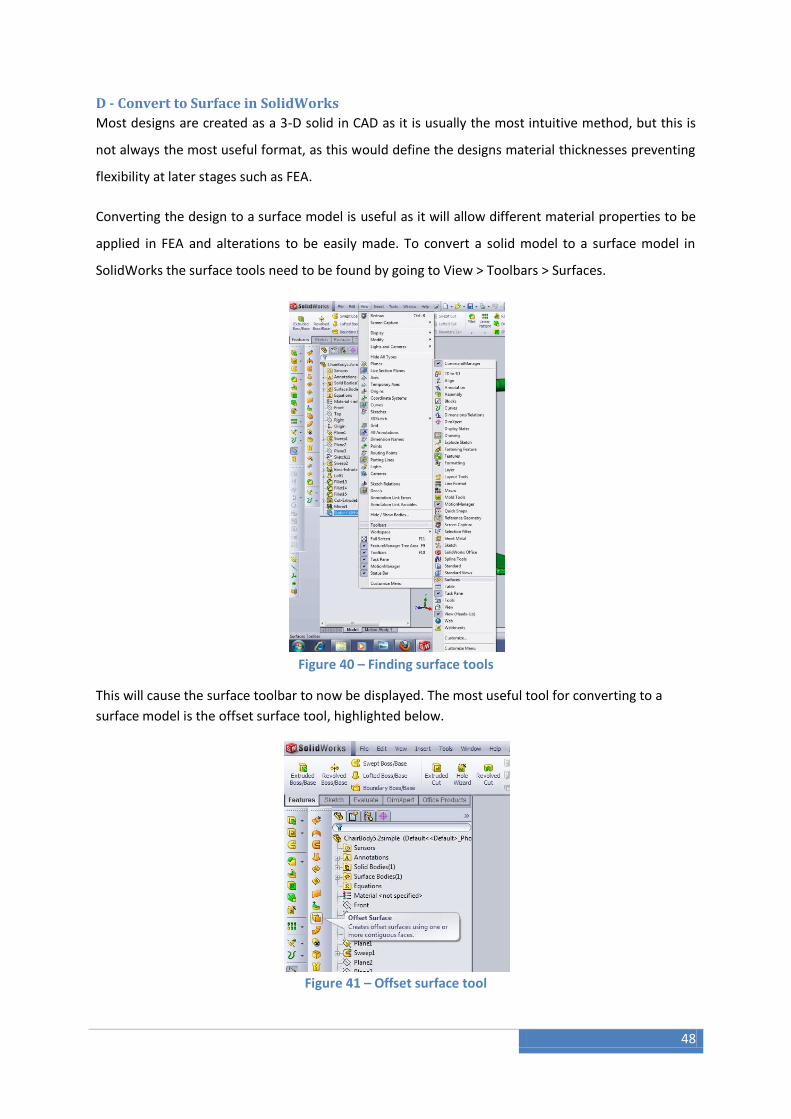
D - Convert to Surface in SolidWorks
Most designs are created as a 3-D solid in CAD as it is usually the most intuitive method, but this is
not always the most useful format, as this would define the designs material thicknesses preventing
flexibility at later stages such as FEA.
Converting the design to a surface model is useful as it will allow different material properties to be
applied in FEA and alterations to be easily made. To convert a solid model to a surface model in
SolidWorks the surface tools need to be found by going to View > Toolbars > Surfaces.
Figure 40 – Finding surface tools
This will cause the surface toolbar to now be displayed. The most useful tool for converting to a
surface model is the offset surface tool, highlighted below.
Figure 41 – Offset surface tool

49
The tool requires all parts to be selected to transfer the whole model to a surface model, making
sure any hidden surfaces are also selected. To get an offset model identical in form to the solid
model, set the offset distance to 0mm, creating a surface on that of the solid model.
Figure 42 – Selecting surfaces to offset
The final stage is hide the solid body by right-clicking Solid Bodies in the Tree and selecting hide, the
part should now be a complete surface model.
Figure 43 – Hiding solid body

50
E - Exporting from SolidWorks for Abaqus
Exporting from SolidWorks is done using SaveAs and selecting the desired format from the
Save as Type drop down menu (IGES or ACIS). The model can then be imported into
Abaqus/CAE using Import from the File menu.
Figure 44 – Exporting in suitable format

51
F - Orthographic Drawing of Wheelchair
Figure 45 – Complete chair orthographic drawing with key dimensions

52
G – Exploded Diagram
Figure 46 – Complete chair exploded diagram


![Fixed tricycle landing gear - wiley.com · PDF fileUsing a reference such as [8], identify one aircraft with fixed tricycle landing gear, one aircraft with retractable tricycle landing](https://static.fdocuments.net/doc/165x107/5aae6fdc7f8b9a190d8c2907/fixed-tricycle-landing-gear-wileycom-a-reference-such-as-8-identify-one-aircraft.jpg)