Design and Finite Element evaluation using Abaqus of a tri ... main initial inputs for the design...
12
2013 SIMULIA Community Conference 1 www.3ds.com/simulia Design and Finite Element evaluation using Abaqus of a tri-axle suspension frame for a passenger bus. Ismael I. Ayala, Edgar Ramírez, Osvaldo Ruiz and Armando Ortiz Universidad Nacional Autónoma de México Abstract: The usage of modern suspension systems in passenger buses increases the performance of the vehicle, to include a new kind of suspension in a passenger bus requires a careful examination of the packaging needs, load transfer and structure characteristics which leads to a safe design to be manufactured. The main objective of this paper is to provide a design proposal for a passenger bus frame to incorporate a commercial tri-axle pneumatic suspension, a system level CAE evaluation is presented to validate and optimize the proposed design. The main initial inputs for the design process were a set of Finite Element Analysis Simulations of the suspension to be implemented. The space requirements were determined by the design of the global bus structure. With these inputs, a series of concepts for the frame design were proposed and evaluated to determine the basis of the design to be constructed upon; a detailed design for each one of the three axles was presented and refined to a final stage where they were evaluated as assembled into the final structure. Following the aforementioned methodology, a structure that is capable of sustaining the selected commercial suspension was obtained. The final proposal consists of detailed CAD files for each of the portions and bus frame assemblies to be constructed. Keywords: Design Optimization, Passenger bus analysis, Frame design, Structure FEM models. 1. Introduction During the past years, the transport industry in Mexico has experimented an increasing development thanks to the interest that Original Equipment Manufacturers (OEMs) have shown by increasingly moving assembly plants to the country. The growth of the transport industry has fostered the creation of national companies which design and build their own products, these companies are constantly looking to bring their products to a worldwide competitive level and thus need to include top of the line systems in them. This paper presents the design process that was followed to incorporate a pneumatic suspension into a bus structure, during the process Abaqus software was used to optimize the design. Figure 1 shows the type of suspension that was considered for implementation into the bus, the front axle consists of an independent suspension with a double wishbone style, while both the drive axle and auxiliary axle are trailing arm suspensions.
Transcript of Design and Finite Element evaluation using Abaqus of a tri ... main initial inputs for the design...

2013 SIMULIA Community Conference 1 www.3ds.com/simulia
Design and Finite Element evaluation using Abaqus of a tri-axle suspension frame for a passenger bus.
Ismael I. Ayala, Edgar Ramírez, Osvaldo Ruiz and Armando Ortiz
Universidad Nacional Autónoma de México
Abstract: The usage of modern suspension systems in passenger buses increases the performance
of the vehicle, to include a new kind of suspension in a passenger bus requires a careful
examination of the packaging needs, load transfer and structure characteristics which leads to a
safe design to be manufactured. The main objective of this paper is to provide a design proposal
for a passenger bus frame to incorporate a commercial tri-axle pneumatic suspension, a system
level CAE evaluation is presented to validate and optimize the proposed design.
The main initial inputs for the design process were a set of Finite Element Analysis Simulations of
the suspension to be implemented. The space requirements were determined by the design of the
global bus structure. With these inputs, a series of concepts for the frame design were proposed
and evaluated to determine the basis of the design to be constructed upon; a detailed design for
each one of the three axles was presented and refined to a final stage where they were evaluated
as assembled into the final structure.
Following the aforementioned methodology, a structure that is capable of sustaining the selected
commercial suspension was obtained. The final proposal consists of detailed CAD files for each of
the portions and bus frame assemblies to be constructed.
Keywords: Design Optimization, Passenger bus analysis, Frame design, Structure FEM models.
1. Introduction
During the past years, the transport industry in Mexico has experimented an increasing
development thanks to the interest that Original Equipment Manufacturers (OEMs) have shown by
increasingly moving assembly plants to the country. The growth of the transport industry has
fostered the creation of national companies which design and build their own products, these
companies are constantly looking to bring their products to a worldwide competitive level and
thus need to include top of the line systems in them. This paper presents the design process that
was followed to incorporate a pneumatic suspension into a bus structure, during the process
Abaqus software was used to optimize the design.
Figure 1 shows the type of suspension that was considered for implementation into the bus, the
front axle consists of an independent suspension with a double wishbone style, while both the
drive axle and auxiliary axle are trailing arm suspensions.

2 2013 SIMULIA Community Conference www.3ds.com/simulia
Figure 1. Suspension for a tri-axle passenger bus. (ZF, 2012)
2. Design process and optimization.
The design was conducted in parallel for the three axles and the process that will be explained
below was conducted for each one of them in the same sequence. The main goal of the design was
to obtain a reliable and safe structure which added the least weight possible to the overall bus
structure. Special interest was given to utilizing standard steel profiles to promote an easy material
procurement, and maintaining simple geometries which could be manufactured in the already
available workshops.
2.1 Determination of the available design space
Since the design was conceived to be constructed within an already existent passenger bus
structure, the first step of the development was to determine how much of the available structure
could be used as a base for the integration of the newly selected suspension. In general it may be
said that, for the three axles, it was decided to utilize the top part of the suspension zone structure
as well as the forward and rearward frames that define this zone. For example figure 2 shows the
available space for the rear axle and the structural members that were selected to become the base
for the design.
Figure 2. Space available for mounting the suspension and usable members for the design shown in color.
The remaining elements that were proposed to be incorporated into the bus structure were
determined to be made out of simple square and rectangular cross section steel tubes which were
used as the basic material for the already existent structure and which are available from steel

2013 SIMULIA Community Conference 3 www.3ds.com/simulia
suppliers in Mexico City, allowing to have an easy procurement process. The characteristics of
these tubes are shown in table 1.
Table 1. Dimensions of structural members selected for the design.
Cross section Material Exterior dimensions Thickness
Square tube ASTM 1020 steel 2" X 2" 0.075"
Rectangular tube ASTM 1020 steel 2" X 3" 0.125"
Both cross sections were used as a combination in the initial structure proposals, with the square
cross section tubes as a basis for the geometry and the rectangular cross section tubes used in the
areas which were expected to be under higher stress levels.
2.2 Generation of the structure geometry.
Once the enveloping structure was determined, a simplified wire model was generated which was
used to locate the fixing points of the springs, dampers and control arms of the suspension as
shown in figure 3. With these locations, the first proposals for the suspension frames were
presented and exported to Abaqus for evaluation, the initial aim of the design was to design a
basic space frame that supported the components of the suspension which could withstand the
loads applied to them by the ride of the bus and further in the design process reinforce this space
frames with supporting elements such as steel plates to lower the stress levels to a safer range. In
these initial proposals, special attention was given to supporting the loads that were applied to the
structure through the springs which were considered to be the highest during normal ride of the
bus.
Figure 3. Process to determine the initial geometry for the structure proposals from a) CAD model of the suspension to b) 3D coordinates for the fixing points of
suspension elements to c) wire model in FEA software.
2.3 Wire model analysis.
The first step in the analysis that was carried to optimize the suspensions was to input quasi static
loads directly into the hard points of the structure in a wire model. The decision to use this kind of
Dampers
Springs
Control Arms

4 2013 SIMULIA Community Conference www.3ds.com/simulia
analysis first was driven by the fact that it requires relatively short time to run the analysis in a PC
and also makes it easier to iterate with several different geometries with relative ease by
modifying the position of the hard points instead of modifying complex geometries as is the case
with a full 3D model.
To generate the wire model for the structures, the following considerations were made:
Each wire representing a structural member was assigned the material properties of
ASTM 1020 steel and the cross sectional dimensions that were mentioned above.
The members that were directly taken from the original bus suspension were considered
to be fixed for the analysis.
The unions between the elements of the structure were idealized without considering the
welds in them.
The loads that were applied were taken from a previous analysis of the suspensions
behavior under acceleration, braking and cornering which was obtained and reported in a
previous paper. The critical cases for each axle were determined to be as follows.
(REYES, 2012)
o For the front axle this is during braking with a negative slope condition, which
increases loads at this axle.
o For drive and auxiliary axles loads obtained under an acceleration condition
with a positive slope are critical.
o Critical loads are in vertical direction, located at air spring fasteners.
o For cornering and braking, on the front axle the largest reaction force still
appears at one air spring while superior and inferior fasteners shown a similar
response to those found for previous conditions, where superior fasteners are
exposed to higher loads than inferior ones.
o Drive and auxiliary axles show a similar distribution of reaction forces at the air
springs as in the case of the front axle, however for both rear axles, a
considerable increase in reaction force is observed in two of the four fasteners.

2013 SIMULIA Community Conference 5 www.3ds.com/simulia
Figure 4. First proposals for the suspension frames analyzed with direct loads
a) front axle structure b) drive axle structure c) supporting axle structure.
From this first analysis, it was determined that modifications needed to be implemented in each
one of the structures to take the level of stresses below 250 MPa. At this stage, it should be
mentioned that this value was selected to be below the yield stress value for ASTM 1020 steel
with a safe factor. The lateral loads that were applied to simulate the cornering behavior of the bus
were the reason for most of the modifications, the modified structures were once again subjected
to the same analysis with direct loading in a cycle to determine the right geometry to withstand
them. The suspension frames geometries that are shown in figure 5 are the result that was finally
obtained to be suitable for further analysis, given that for each of them the stress level was well
below the stated limit.
6 2013 SIMULIA Community Conference www.3ds.com/simulia
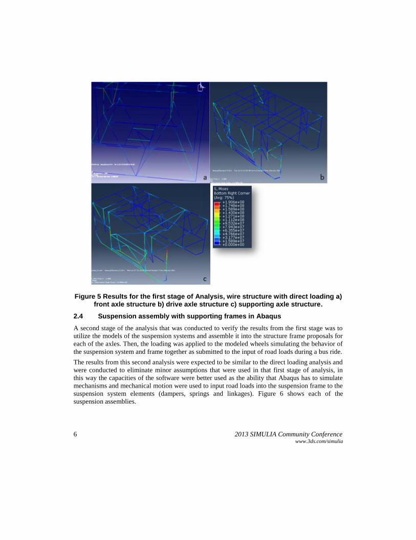
Figure 5 Results for the first stage of Analysis, wire structure with direct loading a) front axle structure b) drive axle structure c) supporting axle structure.
2.4 Suspension assembly with supporting frames in Abaqus
A second stage of the analysis that was conducted to verify the results from the first stage was to
utilize the models of the suspension systems and assemble it into the structure frame proposals for
each of the axles. Then, the loading was applied to the modeled wheels simulating the behavior of
the suspension system and frame together as submitted to the input of road loads during a bus ride.
The results from this second analysis were expected to be similar to the direct loading analysis and
were conducted to eliminate minor assumptions that were used in that first stage of analysis, in
this way the capacities of the software were better used as the ability that Abaqus has to simulate
mechanisms and mechanical motion were used to input road loads into the suspension frame to the
suspension system elements (dampers, springs and linkages). Figure 6 shows each of the
suspension assemblies.

2013 SIMULIA Community Conference 7 www.3ds.com/simulia
Figure 6. Modeled suspension assemblies for each axle a) front axle structure b) drive axle structure c) supporting axle structure.
As expected, the results with this second simulation were very close to the results obtained with
direct loading, no modifications to the geometries were required at this stage and the analysis was
taken to a third stage of 3D model analysis.
2.5 3D model structures analysis.
The third part of the analysis was to input direct loading into a 3D model of the structures. To
create the 3D model, the process followed was to create a CAD model of the structure in
SolidWorks software which was then imported into Abaqus and then minor model changes made
it possible to use it for analysis, with the same applied loads.
This final stage of analysis was expected to validate the previous results and show more detail
about how the geometry of the material that was chosen and the joints between structural members
impacted the behavior of each of the suspension axles frames. The first models that were
generated for this 3D simulation are shown in figure 7.

8 2013 SIMULIA Community Conference www.3ds.com/simulia
Figure 7. Analyzed 3D Abaqus models of the suspension structures for the bus a) front axle structure b) drive axle structure c) supporting axle structure.
The resultant stresses that were obtained in the 3D model simulations were slightly higher than the
results from the wire models, this motivated a revision of the structures proposed by the team and
the addition of supporting members to each axle frame to be able to bring the level of stresses in
every member to below 100 MPa, this value was selected to give a wider safety range to the
structures and to increase fatigue resistance of the structures. .
Based on the results from the previous analysis it was determined that the most critical zones
which needed to be stiffened were:
For the frontal axle, the central members which support the control arms and the fixing
points for the springs.
The drive axle required a redesign of the foremost part of the structure due to the loads in
the control arms during a curve, also the fixing points for the springs were stiffened and
steel plates were added to connect the front and rear parts of the structure.
For the supporting third axle, the reinforced areas were the fixing points for the springs,
and steel plates were also added to connect the front and rear faces of the structure.
As mentioned earlier the previous structure proposals were taken as a space frame basis and
additional elements were proposed for the critical areas. The newly proposed structures included
ASTM 1020 steel plates with 0.125" thickness which aided greatly to stiffen the structure but were
not able to be simulated in a wire model, the modified structures were only subjected to a 3D
model analysis. The same loads as before were applied to the hard points of the structures with a

2013 SIMULIA Community Conference 9 www.3ds.com/simulia
lower limit allowed to validate the improvement of the structures with the added elements. Figure
8 shows the Abaqus 3D models of each modified structure.
Figure 8. 3D model of the modified front axle structure
As it can be seen in figure 8, the last analysis to the modified front structure showed that the stress
level was under 100 MPa in the whole structure and that the stresses concentrate in the front and
rear triangles formed by structural members as well as the structure that connects them through the
center. These zones are the ones that receive the loads from the springs during bus ride.
Figure 9. 3D model of the modified drive axle structure
The structure for the drive axle shows concentrated stresses in the foremost area which supports
the load of the control arms during curves. The supporting elements for the four springs also show
a notable stress level along with the steel plates that connect the front and rear parts of the
structure, this was expected due to the high vertical loads that come through the springs to the
structure. However all stress levels for the structural members remain under 100 MPa.

10 2013 SIMULIA Community Conference www.3ds.com/simulia
Figure 10. 3D models of the modified supporting axle structure.
The structure for the supporting axle shows lower stress level than the other two axles. In this case
the most notorious concentration of stresses occurs on the supporting elements for the springs
during a curve, the loads are visibly transmitted to the front and rear frames by the tubes that
connect these to the springs support. It should be noted that for figures 9 and 10 a deformation
scale factor was used to make the stress concentration easier to be seen.
3. Detailed design and digital assembly of the suspension axles.
The final stage of the work was to detail the suspension frames design in SolidWorks® for
construction and to perform a digital assembly analysis of the suspension systems CAD models
into the proposals to verify that an interference between the models does not exist. Because the
geometries were designed from the beginning with a design for manufacture kind of approach, this
final step was conducted with relative ease and was successful. The CAD models that resulted
from this stage are shown in figure 11.
a
b

2013 SIMULIA Community Conference 11 www.3ds.com/simulia
Figure 11. Digital assembly of the suspension systems into the proposed structures to implement in a passenger bus a) front axle structure b) drive axle
structure c) supporting axle structure.
4. Conclusion
This work presented the design process for the suspension frames in a passenger bus to implement
a pneumatic suspension in each of the three axles. The process was mainly focused on optimizing
these structures to a minimum level of stress to develop a series of Finite Element Analysis that let
the designers to find the critical areas that needed to be reinforced with additional structural
members and to focus efforts into particular details with a 3D model. The capacity of the software
to simulate mechanical elements behavior allowed for a simple dynamical analysis to be
conducted without using other programs, thus reducing significantly the required time for the
analysis.
The use of Finite Element Analysis software made it possible to trial several proposals for the
structures in a very small time compared to what would be needed to try physical prototypes of the
designed structures, this also saves money by focusing effort in the initial stages of the product
development process where changes to a digital model represent negligible costs.
It is important to note that this is only a partial analysis and approximation to the validation of the
bus structure. Even when the threshold of stress used during the analysis allows to assume that the
presented proposals fulfill the conditions that they will endure during use, it must be taken under
account that the models were analyzed in quasi static conditions, fatigue elements were not
analyzed, it is therefore advised that physical measurements of stresses and deformations be
carried to corroborate the results presented here.
c

12 2013 SIMULIA Community Conference www.3ds.com/simulia
5. References
1. Carlos A. Reyes Ruiz, Edgar I. Ramírez Díaz, Osvaldo Ruiz Cervantes, Rafael Schouwenaars,
Armando Ortiz Prado., " Modeling of the suspension of a passenger bus by finite element
software," EngOpt 2012 – 3rd International Conference on Engineering Optimization Rio de
Janeiro, Brazil, 2012.
2. ZF Axle Systems for City Buses and Coaches Catalog, ZF Friedrichshafen AG
3. Abaqus Users Manual, Version 6.10-1, Dassault Systémes Simulia Corp., Providence, RI.
4. Goncalves P.C. and Ambrósio A.C., Optimization of vehicle suspension systems for
improved comfort of road vehicles using flexible multibody dynamics, Kluwer Academic
Publishers, 2004
5. Chandna P., Bhushan G., Singh V. P., Kumar D. and Kumar A., Finite element analysis of a
bus body structure using CAE tools. Kurukshetra University, 2008
6. Hellman A. Simulation of a complete vehicle dynamics using FE code Abaqus. Master’s
thesis. Lulea University of Technology, 2008
7. Milliken, F.W.; Milliken, D.L.: ‘Race car vehicle dynamics’, SAE Int’l, 1995
8. Andrew Deakin, David Crolla, Juan Pablo Ramirez, Ray Hanley, "The Effect of Chassis
Stiffness on Race Car Handling Balance", School of Mech. Eng., The University of Leeds,
2000.
6. Acknowledgement
The authors wish to thank the financial support by DGAPA under grant PAPIME PE100113
“Manual de prácticas de laboratorio de modelado de procesos de manufactura” and PAPIIT
IN117412 “Integración de conocimiento experto para asistir al análisis de falla de elementos
mecánicos”.