Design and Fabrication of Inductors for Induction Heat Treating
18
Design and Fabrication of Inductors for Induction Heat Treating Rob Goldstein, Fluxtrol William Stuehr, Induction Tooling Micah Black, Tucker Induction Systems FOR INDUCTION MELTING AND MASS HEATING, the early induction heating coils were manufactured from copper tubing wrapped in multiple turns around a mandrel. The first induction heat treating coils were developed for crankshaft hardening in the 1930s (Fig. 1, 2) (Ref 1–4). Unlike the melting and mass heating coils, the heat treating induction coils were machined. These inductors consisted of two parts with a hinge on one side that would open and shut around the crankshaft journal. Quench holes were drilled on the inner diameter of the induction coil to deliver quench to the part after heating. This pioneering development was the culmination of many years of hard work by a large team and clearly demonstrated the different requirements for induction heat treating as com- pared to melting and mass heating. During the infancy of induction heat treating coil development, the specific features of the in- duction coil primarily were determined through an analytical-, experience-, and experimental- based method. Concepts for induction coils were created by physicists. Calculations of coil para- meters were determined by manually solving complex equations. Induction coil designs initi- ally were made by draftsmen on blueprints. Most inductors were manufactured by crafts- men using a combination of copper tubing, manually machined components, and copper plates brazed together. Coil optimization was made based on experimental results through the trial-and-error method, because tests and modifications took much less time than the calculations did (Ref 1, 5). While many induction heat treating coils are still manufactured in this way, the tools for the design and fabrication of complex induction heat treating inductors have evolved greatly over the years. For many types of applications, the preferred induction coil style already is known based on years of empirical data. In many cases, comparisons to known results can even determine induction coil dimensions that will lead to a successful heat treating pattern, greatly limiting experimental testing times and shortening development cycles (Ref 1, 5–9). For newer applications or optimization of existing ones, computer modeling tools are being incorporated into the induction coil design procedure. Sophisticated software running on personal computers is capable of making cal- culations in seconds, minutes, or hours that would have taken days, weeks, or months to solve manually. In many cases, no analytical formula exists for complex coils, and the only way to make calculations prior to tests is with a computer modeling program. Induction coil designs and process recipes are “virtually” tested to determine resulting heat patterns. In many cases today (2013), virtual tests and eva- luations can be made more quickly and at a lower cost than physical ones (Ref 10–12). The process of mechanical induction coil design also has evolved over the years. While the initial drawings were made by hand, induction coils now are drawn and detailed using computer- aided design (CAD) packages. Over the past sev- eral years, CAD packages have increased their interactivity with computer-aided manufacturing (CAM) software packages. In many instances, induction coil drawings can be transferred from a CAD drawing to a CAM program into the com- puter numerically controlled machine. This cre- ates the possibility for greater repeatability of complex machined induction coils (Ref 13, 14). Methods of Induction Heat Treating Today (2014), there are many different types of induction heat treating coils. The induction heat treating coil style depends on the induction heat treating process. All induction heat treating processes can be classified in two categories: single shot and scanning, based on whether the induction coil is moving (excluding rotation) relative to the part during the heating process. A brief description is given subsequently, because more in-depth information on induction heat treating equipment is discussed in other sections in this article. In single-shot (Fig. 3) induction heat treating applications, the position of the induction coil relative to the heated length of the part does not move. In many single-shot heating ASM Handbook, Volume 4C, Induction Heating and Heat Treatment V. Rudnev and G.E. Totten, editors Copyright # 2014 ASM International W All rights reserved www.asminternational.org Fig. 1 Tocco coil. Source: Ref 1 Fig. 2 Vologdin coil
-
Upload
fluxtrol-inc -
Category
Engineering
-
view
226 -
download
2
Transcript of Design and Fabrication of Inductors for Induction Heat Treating

Design and Fabrication of Inductors forInduction Heat TreatingRob Goldstein, FluxtrolWilliam Stuehr, Induction ToolingMicah Black, Tucker Induction Systems
FOR INDUCTION MELTING AND MASSHEATING, the early induction heating coilswere manufactured from copper tubing wrappedin multiple turns around a mandrel. The firstinduction heat treating coils were developed forcrankshaft hardening in the 1930s (Fig. 1, 2)(Ref 1–4). Unlike the melting and mass heatingcoils, the heat treating induction coils weremachined. These inductors consisted of twoparts with a hinge on one side that would openand shut around the crankshaft journal. Quenchholes were drilled on the inner diameter of theinduction coil to deliver quench to the part afterheating. This pioneering development was theculmination of many years of hard work by alarge team and clearly demonstrated the differentrequirements for induction heat treating as com-pared to melting and mass heating.During the infancy of induction heat treating
coil development, the specific features of the in-duction coil primarily were determined throughan analytical-, experience-, and experimental-
based method. Concepts for induction coils werecreated by physicists. Calculations of coil para-meters were determined by manually solvingcomplex equations. Induction coil designs initi-ally were made by draftsmen on blueprints.Most inductors were manufactured by crafts-men using a combination of copper tubing,manually machined components, and copperplates brazed together. Coil optimization wasmade based on experimental results throughthe trial-and-error method, because tests andmodifications took much less time than thecalculations did (Ref 1, 5).While many induction heat treating coils are
still manufactured in this way, the tools forthe design and fabrication of complex inductionheat treating inductors have evolved greatlyover the years. For many types of applications,the preferred induction coil style already isknown based on years of empirical data. Inmany cases, comparisons to known results caneven determine induction coil dimensions thatwill lead to a successful heat treating pattern,greatly limiting experimental testing times andshortening development cycles (Ref 1, 5–9).For newer applications or optimization of
existing ones, computer modeling tools are beingincorporated into the induction coil designprocedure. Sophisticated software running on
personal computers is capable of making cal-culations in seconds, minutes, or hours thatwould have taken days, weeks, or months tosolve manually. In many cases, no analyticalformula exists for complex coils, and the onlyway to make calculations prior to tests is witha computer modeling program. Induction coildesigns and process recipes are “virtually”tested to determine resulting heat patterns. Inmany cases today (2013), virtual tests and eva-luations can be made more quickly and at alower cost than physical ones (Ref 10–12).The process of mechanical induction coil
design also has evolved over the years. Whilethe initial drawings weremade by hand, inductioncoils now are drawn and detailed using computer-aided design (CAD) packages. Over the past sev-eral years, CAD packages have increased theirinteractivity with computer-aided manufacturing(CAM) software packages. In many instances,induction coil drawings can be transferred froma CAD drawing to a CAM program into the com-puter numerically controlled machine. This cre-ates the possibility for greater repeatability ofcomplex machined induction coils (Ref 13, 14).
Methods of Induction Heat Treating
Today (2014), there are many different typesof induction heat treating coils. The inductionheat treating coil style depends on the inductionheat treating process. All induction heat treatingprocesses can be classified in two categories:single shot and scanning, based on whether theinduction coil is moving (excluding rotation)relative to the part during the heating process.A brief description is given subsequently, becausemore in-depth information on induction heattreating equipment is discussed in other sectionsin this article.In single-shot (Fig. 3) induction heat treating
applications, the position of the inductioncoil relative to the heated length of the partdoes not move. In many single-shot heating
ASM Handbook, Volume 4C, Induction Heating and Heat TreatmentV. Rudnev and G.E. Totten, editors
Copyright # 2014 ASM InternationalW
All rights reservedwww.asminternational.org
Fig. 1 Tocco coil. Source: Ref 1 Fig. 2 Vologdin coil
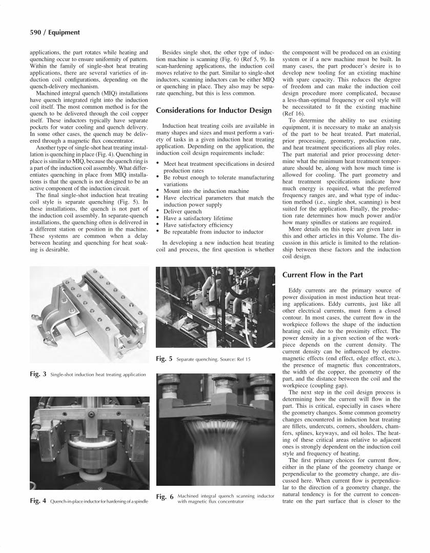
applications, the part rotates while heating andquenching occur to ensure uniformity of pattern.Within the family of single-shot heat treatingapplications, there are several varieties of in-duction coil configurations, depending on thequench-delivery mechanism.Machined integral quench (MIQ) installations
have quench integrated right into the inductioncoil itself. The most common method is for thequench to be delivered through the coil copperitself. These inductors typically have separatepockets for water cooling and quench delivery.In some other cases, the quench may be deliv-ered through a magnetic flux concentrator.Another type of single-shot heat treating instal-
lation is quenching in place (Fig. 4). Quenching inplace is similar toMIQ, because the quench ring isa part of the induction coil assembly. What differ-entiates quenching in place from MIQ installa-tions is that the quench is not designed to be anactive component of the induction circuit.The final single-shot induction heat treating
coil style is separate quenching (Fig. 5). Inthese installations, the quench is not part ofthe induction coil assembly. In separate-quenchinstallations, the quenching often is delivered ina different station or position in the machine.These systems are common when a delaybetween heating and quenching for heat soak-ing is desirable.
Besides single shot, the other type of induc-tion machine is scanning (Fig. 6) (Ref 5, 9). Inscan-hardening applications, the induction coilmoves relative to the part. Similar to single-shotinductors, scanning inductors can be either MIQor quenching in place. They also may be sepa-rate quenching, but this is less common.
Considerations for Inductor Design
Induction heat treating coils are available inmany shapes and sizes and must perform a vari-ety of tasks in a given induction heat treatingapplication. Depending on the application, theinduction coil design requirements include:
� Meet heat treatment specifications in desiredproduction rates
� Be robust enough to tolerate manufacturingvariations
� Mount into the induction machine� Have electrical parameters that match the
induction power supply� Deliver quench� Have a satisfactory lifetime� Have satisfactory efficiency� Be repeatable from inductor to inductor
In developing a new induction heat treatingcoil and process, the first question is whether
the component will be produced on an existingsystem or if a new machine must be built. Inmany cases, the part producer’s desire is todevelop new tooling for an existing machinewith spare capacity. This reduces the degreeof freedom and can make the induction coildesign procedure more complicated, becausea less-than-optimal frequency or coil style willbe necessitated to fit the existing machine(Ref 16).To determine the ability to use existing
equipment, it is necessary to make an analysisof the part to be heat treated. Part material,prior processing, geometry, production rate,and heat treatment specifications all play roles.The part material and prior processing deter-mine what the minimum heat treatment temper-ature should be, along with how much time isallowed for cooling. The part geometry andheat treatment specifications indicate howmuch energy is required, what the preferredfrequency ranges are, and what type of induc-tion method (i.e., single shot, scanning) is bestsuited for the application. Finally, the produc-tion rate determines how much power and/orhow many spindles or stations are required.More details on this topic are given later in
this and other articles in this Volume. The dis-cussion in this article is limited to the relation-ship between these factors and the inductioncoil design.
Current Flow in the Part
Eddy currents are the primary source ofpower dissipation in most induction heat treat-ing applications. Eddy currents, just like allother electrical currents, must form a closedcontour. In most cases, the current flow in theworkpiece follows the shape of the inductionheating coil, due to the proximity effect. Thepower density in a given section of the work-piece depends on the current density. Thecurrent density can be influenced by electro-magnetic effects (end effect, edge effect, etc.),the presence of magnetic flux concentrators,the width of the copper, the geometry of thepart, and the distance between the coil and theworkpiece (coupling gap).The next step in the coil design process is
determining how the current will flow in thepart. This is critical, especially in cases wherethe geometry changes. Some common geometrychanges encountered in induction heat treatingare fillets, undercuts, corners, shoulders, cham-fers, splines, keyways, and oil holes. The heat-ing of these critical areas relative to adjacentones is strongly dependent on the induction coilstyle and frequency of heating.The first primary choices for current flow,
either in the plane of the geometry change orperpendicular to the geometry change, are dis-cussed here. When current flow is perpendicu-lar to the direction of a geometry change, thenatural tendency is for the current to concen-trate on the part surface that is closer to the
Fig. 3 Single-shot induction heat treating application
Fig. 4 Quench-in-place inductor forhardeningof a spindleFig. 6 Machined integral quench scanning inductor
with magnetic flux concentrator
Fig. 5 Separate quenching. Source: Ref 15
590 / Equipment

induction coil, due to the proximity effect. Anadditional consideration is that near the ends ofthe closer section to where the distance increases,there is either a decrease or an increase in heat-ing, depending on whether the part is magneticor nonmagnetic due to the electromagnetic endeffect. For hardening applications, there is someincrease, and for tempering there is a decrease.The magnitude of the change depends on thefrequency (Fig. 7) (Ref 12).When the current flow is in the direction of a
geometry change, the current flows under theinductor in a width approximating that of theinduction coil. When the dimension changeoccurs, the current flow follows the contour ofthe part through this dimensional change. Atthe point of the dimension change, the changein heating is governed by the electromagneticedge effect. The edge effect tends to be smallerthan the end effect, hence meaning a smallertemperature differential in this area. As the dis-tance between the coil and part increases, theamount of current remains nearly the same,
but the current begins to flow over a widerlength. The less concentrated heating leads tolower power densities (Fig. 8). The differencebetween the power densities tends to be smallerthan when current flow is in the direction of thegeometry change than when it is perpendicular.To illustrate the concept, consider the case of
a simple spindle with one bearing race and ashoulder (Fig. 9). The heat treating pattern isthe light-gray area. This part could be heatedeither by scanning or single shot. The scanninginductor almost certainly would be an encir-cling inductor with a length less than the pat-tern length. Within single shot, it also couldbe hardened by a machined encircling inductoror a so-called encircling/nonencircling inductor.For an encircling inductor (scanning or single
shot), the current flow in the coil and part tendto take the shortest path and flow along theinductor inside diameter and bearing surfacediameter. To compensate for this tendency,it is necessary to vary the gap between thecoil and part to use the proximity effect to
compensate for the shorter length for currentflow. In the area of the radius, there is a transi-tion from the smaller gaps on the flange to thelarger gaps on the diameter. For a single-turnmachined inductor, the coil design in this areainvolves a delicate balance to achieve sufficientdepth in the fillet without heating too deeply inthe bearing area just above the fillet. For casedepths that are large relative to the cross sec-tion, this becomes more difficult because coretemperatures increase, resulting in reduced con-ductive heat extraction. For a shorter scanningcoil, this task is made easier by using a mag-netic flux concentrator to drive current downfrom the shaft and into the radius of the part(Fig. 10).Encircling/nonencircling inductors consist of
multiple partial loops connected by copper railsthat are contoured to the part surface (Fig. 11).For these inductors, the part must rotate toensure even heating. For a simple part such asthis, likely only one top and one bottom partialloop would be required. In this case, currentflows under the coil turns and follows the con-tour of the coil in the part. In this way, the topand bottom of the pattern are controlled by theend loops, and the rails determine the pattern inthe central area. By following the rails along thepart surface, the current flows through the radius.
Fig. 7 End-effect drawing
Fig. 8 Edge-effect drawing
Fig. 9 Heat pattern for spindle
Fig. 10 Encircling drawing for spindle
Design and Fabrication of Inductors for Induction Heat Treating / 591
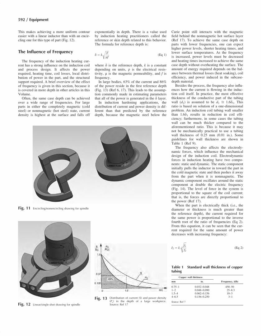
This makes achieving a more uniform contoureasier with a linear inductor than with an encir-cling one for this type of part (Fig. 12).
The Influence of Frequency
The frequency of the induction heating cur-rent has a strong influence on the induction coiland process design. It affects the powerrequired, heating time, coil losses, local distri-bution of power in the part, and the structuralsupport required. A brief overview of the effectof frequency is given in this section, because itis covered in more depth in other articles in thisVolume.Often, the same case depth can be achieved
over a wide range of frequencies. For largeparts in either the completely magnetic (coldsteel) or nonmagnetic (hot steel) state, currentdensity is highest at the surface and falls off
exponentially in depth. There is a value usedby induction heating practitioners called thereference or skin depth related to this behavior.The formula for reference depth is:
d ¼ k
ffiffiffiffiffi
rmf
r
(Eq 1)
where d is the reference depth, k is a constantdepending on units, r is the electrical resis-tivity, m is the magnetic permeability, and f isfrequency.In large bodies, 63% of the current and 86%
of the power reside in the first reference depth(Fig. 13) (Ref 6, 17). This leads to the assump-tion commonly made in estimating parametersthat all of the power is generated in the d layer.In induction hardening applications, the
distribution of current and power density is dif-ferent than that predicted by the referencedepth, because the magnetic steel below the
Curie point still interacts with the magneticfield behind the nonmagnetic hot surface layer(Ref 17). To achieve the same case depth onparts with lower frequencies, one can expecthigher power levels, shorter heating times, andlower surface temperatures. As the frequencyis increased, power levels must be decreasedand heating times increased to achieve the samecase depth without overheating the surface. Theamount of energy required depends on the bal-ance between thermal losses (heat soaking), coilefficiency, and power induced in the subcase-depth material.Besides the process, the frequency also influ-
ences how the current is flowing in the induc-tion coil itself. In practice, the most effectivethickness of the conductive part of the tubingwall (d1) is assumed to be d1 ffi 1.6d1. Thisratio is based on solution of a one-dimensionalproblem. An induction coil tubing wall smallerthan 1.6d1 results in reduction in coil effi-ciency; furthermore, in some cases the tubingwall can be much thicker compared to theaforementioned ratio. This is because it maynot be mechanically practical to use a tubingwall thickness of 0.25 mm (0.01 in.). Someguidelines for wall thickness are shown inTable 1 (Ref 9).The frequency also affects the electrody-
namic forces, which influence the mechanicaldesign of the induction coil. Electrodynamicforces in induction heating have two compo-nents: static and dynamic. The static componentinitially pulls the inductor in toward the part inthe cold magnetic state and then pushes it awayfrom the part when it is nonmagnetic. Thedynamic component oscillates around the staticcomponent at double the electric frequency(Fig. 14). The level of force in the system isproportional to the square of the coil current;that is, the forces are directly proportional tothe power (Ref 17).When the part is electrically thick (i.e., the
diameter or thickness is much greater thanthe reference depth), the current required forthe same power is proportional to the inversefourth root of the ratio of frequencies (Eq 2).From this equation, it can be seen that the cur-rent required for the same amount of powerdecreases with increasing frequency:
I2 ¼ I1
ffiffiffiffi
f1f2
4
s
(Eq 2)
Fig. 11 Encircling/nonencircling drawing for spindle
Fig. 12 Linear/single-shot drawing for spindle
Fig. 13 Distribution of current (S) and power density(Pv) in the depth of a large workpiece.Source: Ref 17
Table 1 Standard wall thickness of coppertubing
Copper wall thickness
Frequency, kHzmm in.
0.75–1 0.032–0.048 450–501–2 0.048–0.090 25–8.31.5–4 0.062–0.156 10–34–6.5 0.156–0.250 3–1
Source: Ref 7
592 / Equipment

Due to this, the electrodynamic forces arehigher at lower frequencies. Additionally,power levels generally tend to be higher atlower frequencies, increasing the electrody-namic forces even more. Therefore, the lowerthe frequency, the more robust the mechanicaldesign of the induction coil should be. In addi-tion to heavier copper wall thicknesses, the coilsupporting structure also must be stronger towithstand the mechanical loading to whichthe coil is exposed. This is especially true onsingle-shot coils.
Control of Heating in DifferentAreas of the Part
In many induction heat treating applications,there is a requirement to selectively hardensome areas of the workpiece and not hardenothers. In other instances, different case depthsare desired in different areas of the part. Often,it is necessary to achieve these various targetsin the same induction heat treating operation.For scan hardening applications, these varia-
tions typically are compensated for by adjustingthe power and scan speed as the part traversesthrough the induction coil. For single-shotinduction coils, it is necessary to accommodatethese changes in the coil design. There are threemain tools for adjustment of the coil design:coupling gap, coil copper profile, and magneticflux controllers.The coupling gap is the most straightforward
way to control the heat pattern. The closer thecoil is to the part, the greater the intensity of heat-ing in this area relative to other areas. This isbecause the current in the part flows in a nar-rower band more closely approximating that inthe induction heating coil. With increasing cou-pling gap, the current spreads out over a longerlength, resulting in lower current density andpower density.Another method to control the heat pattern is
to change the cross-sectional profile of the cop-per coil. The section(s) of the coil turn thatfaces the part and carries the majority of the
current is referred to as the heat face of thecoil. For induction coils with a single heatface, power profiling is achieved by varyingthe geometry of the heat face (Fig. 15). Forinstance, to shorten the transition zones at theends of the coil, it is common to have a largergap in the middle of the coil than on the ends.This method is commonly used for controllingthe end of a heat treating pattern where it is de-sirable to keep the pattern out of an undercut ora snap ring groove. This helps to compensatefor the divergence of magnetic flux and theadditional thermal losses near the end of thecoil.An example of this is hardening the bearing
of a crankshaft using an encircling coil (clam-shell or sharp-C technology, Ref 9). Using theFlux 2D computer simulation program, it ispossible to make a comparison to see the effectof the copper profiling on the temperature dis-tribution. Figure 16 shows a simplified exampleof a coil for this technology. The lines on thepart represent the minimum and maximum casedepth. The frequency for this comparison is50 kHz. The coupling gap is 2 mm (0.08 in.),and the coil has thin plates of Fluxtrol 50 con-centrator on both sides to prevent coupling withthe sidewalls. At 2.5 mm (0.10 in.) from eachend of the coil, the copper is recessed 1 mm(0.04 in.). This coil is compared to a coil with
the exact same geometry, except the centralsection of the inductor is not recessed. Theheating time for both cases is 4 s.The temperature distribution in the coil
without profiling is shown in Fig. 17. The areaof high temperature begins to taper off wellbefore the end of the heat face and the mini-mum required length of the pattern. The surfacetemperature already is high, so it is not possibleto increase heating to lengthen the pattern.Figure 18 shows the temperature distribution
for the coil with a profiled face. It is clear fromthis image that the area of high temperatureextends significantly longer than for the coilwithout profiling. The minimum heat treatmentwidth is met with a lower maximum surfacetemperature. For better comparison betweenthe two cases, Fig. 19 compares the surfacetemperature in length.For coils with multiple heat faces or sec-
tions, in addition to the coupling gap, the heatpattern also can be controlled by changing thewidth of the heat face from section to section.Power density in the part is proportional tothe current density squared. If it is assumedthat all of the current in the coil is transferredto the part and is flowing directly under theheat face of the induction coil, then the cur-rent density will be inversely proportionalto the width of the heat face. This means
Fig. 15 Drawing showing inductor heat face
Fig. 16 Nonrotational inductor cross section used for simulation
Fig. 14 Diagram showing relationship between current(i), static component of force (Fc), and dynamicforce (F ). Source: Ref 17
Design and Fabrication of Inductors for Induction Heat Treating / 593

that power density will be proportional to theinverse square of the width of the heat face.The real effect is significantly less, becausenot all of the current is on the heat face, andsome of the flux outside the coil couples withthe part.For heating of a round part with a linear coil,
the effect is not as strong due to the nonuniformgap between the rectangular coil and the roundpart.To demonstrate the effect of the heat face
width, a comparison is made for heating a
12.7 mm (0.5 in.) thick plate with a 9.5 by12.7 mm (⅜ by 0.5 in.) tube and a 12.7 mm(0.5 in.) square copper tube. Computer simula-tion program Flux 2D is used for calculationof the electromagnetic problem. The top halfof the plate has the properties of steel abovethe Curie point, and the bottom half hasthe properties of cold steel. The frequency is10 kHz, and the coupling gap is set to 3.2 mm(⅛ in.). The same current, 3000 A, is used forboth coils. The magnetic field and power den-sity distributions for both cases are shown in
Fig. 20. Ideally, the power density would be78% higher for the 9.5 mm (⅜ in.) heat facecompared to the 12.7 mm (0.5 in.) one. In real-ity, this difference in maximum power densityis only approximately 17%. This is due to thelarge amount of current that is flowing in thepart outside the heat face of the coil.A more effective way to control the distribu-
tion of heat in the length of an inductor is to usemagnetic flux controllers. For induction heattreating applications, the most common materi-als used as magnetic flux controllers are siliconsteel laminations and soft magnetic compositematerials. Magnetic flux concentrators providea low reluctance path for the magnetic field toflow. The result is that the magnetic field goesfrom being widely distributed in space to beingconcentrated around the coil. This causes nearlyall of the current flowing on the sidewalls of thecopper coil to be pushed down to the heat face.This results in the current in the part being con-centrated more strongly underneath the heatface of the coil.To demonstrate the effect of the concentrator,
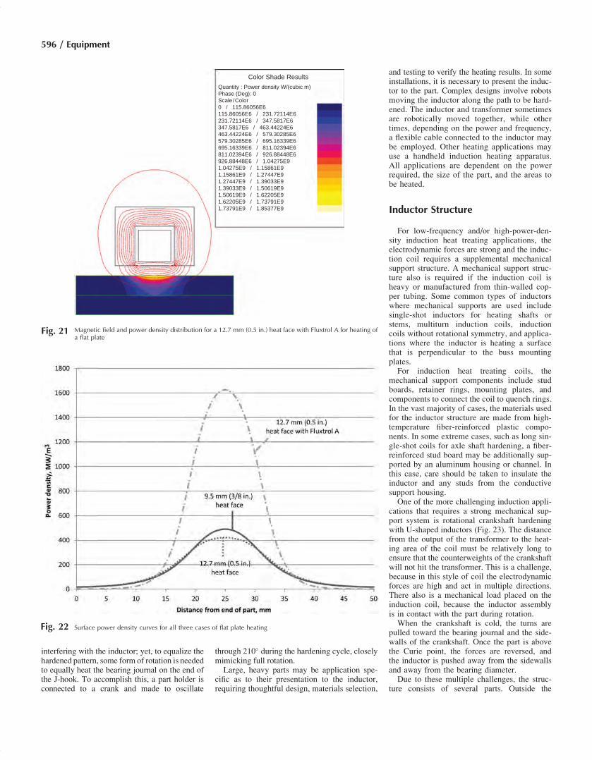
a comparison is made for heating a 12.7 mm(0.5 in.) thick plate with a 12.7 mm (0.5 in.)square copper tube, with and without a C-shapedconcentrator applied. The flux-concentratingmaterial used is Fluxtrol A. The other condi-tions are the same as in the case for the heatface variation study. The magnetic field andpower density distributions for the coil withconcentrator are shown in Fig. 21.The magnetic field and power density are
much more concentrated when the magneticflux controller is applied. The surface powerdensity curves from the left to the right sideof the part are shown in Fig. 22 for all threecases. It is clear that the application of a mag-netic flux controller is a stronger method ofcontrolling the heat pattern in the length of acoil than the use of copper profiling. It also ispossible to more smoothly distribute the patternbetween different areas by profiling the poles ofthe concentrator rather than having steps in theinduction coil. For linear coils heating a roundpart, the influence of both heat face width anda magnetic flux controller is less dramatic thanin the case of a flat plate, due to the divergenceof the part from the coil. More information onmagnetic flux controller selection and uses iscontained in the article “Magnetic Flux Con-trollers in Induction Heating and Melting” inthis Volume.
Presentation of the Part to theInductor
During the initial inductor design, a method ofholding the part and presenting it to the inductormust be addressed. Some considerations are:
� What is the part size and weight?� What is the process hardening or tempering?� Is it to be scanned or single shot?
Color Shade ResultsQuantity : Temperature Deg. Celsius
Time (s.) : 4 Phase (Deg): 0
Scale / Color
20.06464 / 86.92299
86.92299 / 153.78134
153.78134 / 220.63969
220.63969 / 287.49805
287.49805 / 354.35638
354.35638 / 421.21478
421.21478 / 488.07312
488.07312 / 554.93146
554.93146 / 621.78986
621.78986 / 688.64819
688.64819 / 755.50653
755.50653 / 822.36487
822.36487 / 889.22321
889.22321 / 956.0816
956.0816 / 1.02294E3
1.02294E3 / 1.0898E3
Fig. 17 Temperature distribution with a nonprofiled heat face
Color Shade Results
Quantity : Temperature Deg. Celsius
Time (s.) : 4 Phase (Deg): 0
Scale / Color
20.08923 / 83.79922
83.79922 / 147.50919
147.50919 / 211.21918
211.21918 / 274.92917
274.92917 / 338.63913
338.63913 / 402.34912
402.34912 / 466.05911
466.05911 / 529.7691
529.7691 / 593.47913
593.47913 / 657.18909
657.18909 / 720.89905
720.89905 / 784.60907
784.60907 / 848.31903
848.31903 / 912.02905
912.02905 / 975.73901
975.73901 / 1.03945E3
Fig. 18 Temperature distribution with a profiled heat face
594 / Equipment

� Is the part to be rotated during processing?� What is the rate of production?� What type of materials handling equipment
is needed?� How and where on the part can it be held?� What is the kilowatt requirement and power
supply frequency?� How is it to be loaded into the inductor:
manually or mechanically?� What is the quench method: spray, dunk,
agitated bath, still air, or air blast?� What types of holding devices are to be used:
centers, chuck, or special grippers?
Depending on the process, there could beseveral mechanical methods to grip and presenta part to the inductor. In high-production appli-cations, an entire machine may be designed andbuilt for a specific materials handling process.In limited-production runs, however, a simplelift-and-rotate device within a quench tank maybe employed. Either way, a decision must bemade on how to hold the part.Part holding and presentation can be as easy
as chucking the part or as complicated as hav-ing to hold and rotate the part while it is heatedentirely. In any scenario, the electromagnetic
fields from the induction coil should be consid-ered in the design of the holding device and itseffect on the part. Magnetic steels in close pro-ximity to the inductor will heat; therefore, suffi-cient air space around the inductor is prudent.Common nonmagnetic part-holding materials,such as 300-series stainless steels, aluminum,and brass, can be heated when in close prox-imity to the inductor, but with a less significanteffect. When designed specific to an applica-tion, certain ceramics also make excellent part-holding devices.For example, typical to induction hardening
applications is the lift-and-rotate method withina quench tank. A part of reasonable size andshape, such as an automotive wheel spindle, ismounted onto a part holder made from nonmag-netic stainless steel. An upper center of thesame material is used to stabilize the part dur-ing rotation. An inductor designed to heat treatthe wheel spindle is installed onto the powersupply mounting foot within the tank. A sprayquench is integral to the inductor. The wheelspindle is loaded in the holder and raised tothe inductor. Rotation starts, the inductionpower is applied, the wheel spindle is heatedand then immediately quenched, and the spin-dle is lowered and unloaded. This entire processtakes less than 30 s. In a high-production appli-cation, throughput would be multiplied withadditional heating stations employing variousmaterials handling systems.While many examples of heat treating are
typical, when parts are large and/or geometri-cally difficult, the presentation to the inductormay require engineering. For many induction-hardened parts, rotation during heating equalizesthe heat treating pattern. Some parts, suchas truck steering arms in the shape of the letter“J,” cannot be rotated 360� due to the J-hookFig. 19 Comparison of temperature distributions with and without profiling for nonrotational heating of a crankshaft
Color Shade Results
(a) (b)
Quantity : Power density W/(cubic m)
Scale / Color0 / 35.01103E6
Phase (Deg) 0
35.01103E6 / 70.02206E670.02206E6 / 105.03309E6105.03309E6 / 140.04411E6140.04411E6 / 175.05515E6175.05515E6 / 210.06618E6210.06618E6 / 245.0772E6245.0772E6 / 280.08822E6280.08822E6 / 315.09923E6315.09923E6 / 350.11027E6350.11027E6 / 385.12131E6385.12131E6 / 420.13232E6420.13232E6 / 455.14336E6455.14336E6 / 490.15437E6490.15437E6 / 525.16541E6525.16541E6 / 560.17645E6
Color Shade ResultsQuantity : Power density W/(cubic m)
Scale / Color0 / 29.92064E6
Phase (Deg) 0
29.92064E6 / 59.84129E659.84129E6 / 89.76194E689.76194E6 / 119.68258E6119.68258E6 / 149.60323E6149.60323E6 / 139.52387E6139.52387E6 / 209.44451E6209.44451E6 / 239.36515E6239.36515E6 / 269.28579E6269.28579E6 / 299.20643E6299.20643E6 / 329.1271E6329.1271E6 / 359.04774E6359.04774E6 / 388.96830E6388.96830E6 / 418.88902E6418.88902E6 / 448.80966E6448.80966E6 / 478.7303E6
10 / 865.19256E-6
11 / 970.83917E-6
12 / 1.07649E-3
8 / 03383339E-6
9 / 759.54595E-6
Fig. 20 Comparison of (a) 9.5 mm (⅜ in.) and (b) 12.7 mm (0.5 in.) heat faces for heating of a flat plate
Design and Fabrication of Inductors for Induction Heat Treating / 595
interfering with the inductor; yet, to equalize thehardened pattern, some form of rotation is neededto equally heat the bearing journal on the end ofthe J-hook. To accomplish this, a part holder isconnected to a crank and made to oscillate
through 210� during the hardening cycle, closelymimicking full rotation.Large, heavy parts may be application spe-
cific as to their presentation to the inductor,requiring thoughtful design, materials selection,
and testing to verify the heating results. In someinstallations, it is necessary to present the induc-tor to the part. Complex designs involve robotsmoving the inductor along the path to be hard-ened. The inductor and transformer sometimesare robotically moved together, while othertimes, depending on the power and frequency,a flexible cable connected to the inductor maybe employed. Other heating applications mayuse a handheld induction heating apparatus.All applications are dependent on the powerrequired, the size of the part, and the areas tobe heated.
Inductor Structure
For low-frequency and/or high-power-den-sity induction heat treating applications, theelectrodynamic forces are strong and the induc-tion coil requires a supplemental mechanicalsupport structure. A mechanical support struc-ture also is required if the induction coil isheavy or manufactured from thin-walled cop-per tubing. Some common types of inductorswhere mechanical supports are used includesingle-shot inductors for heating shafts orstems, multiturn induction coils, inductioncoils without rotational symmetry, and applica-tions where the inductor is heating a surfacethat is perpendicular to the buss mountingplates.For induction heat treating coils, the
mechanical support components include studboards, retainer rings, mounting plates, andcomponents to connect the coil to quench rings.In the vast majority of cases, the materials usedfor the inductor structure are made from high-temperature fiber-reinforced plastic compo-nents. In some extreme cases, such as long sin-gle-shot coils for axle shaft hardening, a fiber-reinforced stud board may be additionally sup-ported by an aluminum housing or channel. Inthis case, care should be taken to insulate theinductor and any studs from the conductivesupport housing.One of the more challenging induction appli-
cations that requires a strong mechanical sup-port system is rotational crankshaft hardeningwith U-shaped inductors (Fig. 23). The distancefrom the output of the transformer to the heat-ing area of the coil must be relatively long toensure that the counterweights of the crankshaftwill not hit the transformer. This is a challenge,because in this style of coil the electrodynamicforces are high and act in multiple directions.There also is a mechanical load placed on theinduction coil, because the inductor assemblyis in contact with the part during rotation.When the crankshaft is cold, the turns are
pulled toward the bearing journal and the side-walls of the crankshaft. Once the part is abovethe Curie point, the forces are reversed, andthe inductor is pushed away from the sidewallsand away from the bearing diameter.Due to these multiple challenges, the struc-
ture consists of several parts. Outside the
Color Shade Results
Quantity : Power density W/(cubic m)
Phase (Deg): 0
Scale/Color
0 / 115.86056E6
115.86056E6 / 231.72114E6
231.72114E6 / 347.5817E6
347.5817E6 / 463.44224E6
463.44224E6 / 579.30285E6
579.30285E6 / 695.16339E6
695.16339E6 / 811.02394E6
811.02394E6 / 926.88448E6
926.88448E6 / 1.04275E9
1.04275E9 / 1.15861E9
1.15861E9 / 1.27447E9
1.27447E9 / 1.39033E9
1.39033E9 / 1.50619E9
1.50619E9 / 1.62205E9
1.62205E9 / 1.73791E9
1.73791E9 / 1.85377E9
Fig. 21 Magnetic field and power density distribution for a 12.7 mm (0.5 in.) heat face with Fluxtrol A for heating ofa flat plate
Fig. 22 Surface power density curves for all three cases of flat plate heating
596 / Equipment

inductor there typically are two brass or alumi-num side plates. All of the components areanchored to the side plates, including the induc-tion coil. To prevent contact of the inductorwith the part, ceramic or carbide guide shoesare placed in three places (just after the endsof the loops and between the two loops) aroundthe perimeter on both sides of the inductor. Theceramic guide shoes typically are mounted tobrass or aluminum side plates.In addition to the guide shoes, the side plates
also help to keep the induction coil in position.The inductor typically is held in at least threeplaces: the ends of each loop by a stud andG-11 component, and the leads area by a G-11component. Other components that may be apart of the structure in crankshaft coils includeleaders to facilitate the coil loading, quenchheads, and side support composites to increasethe rigidity of the assembly.
Coil Leads/Busswork and Contacts
With induction coils, there is an intermediatebody between the coil head (the part where theinduction heat treating process is conducted)and the heat station, power supply, or quick-change adapter. This section of the inductor isreferred to as the coil leads or busswork. Therole of the coil leads or busswork is to mechan-ically and electrically connect the induction coilhead to the power supply. Often, the coolingwater for the coil head also is supplied throughthe leads.Good design practice is that the leads should
be close together, with a piece of syntheticfluorine-containing resin between them toelectrically separate the two leads from oneanother. It also is good practice to make theheight of the busswork significantly longer thanthe length of the heat face of the induction coil.In most cases, the coil leads or busswork
must carry the same current that is in the induc-tion coil head itself. Because the coil leads/
busswork carry a high-frequency current, thecoil leads generate heat from eddy currents.The current is drawn to the side of the bussbarthat faces the opposing bussbar by the proxim-ity effect. The current density in the leads isinversely proportional to the length of the inter-face, and hence, the losses are approximatelyproportional to the length squared. The proxim-ity of the two leads to each other primarily influ-ences the voltage drop in the leads. The closerthe leads are, the lower the inductance of theleads and hence the lower the voltage drop.The coil contacts range from simple flared or
compression fittings to machined blocks withkeys to ensure location, depending on the mat-ing surface. For heat treating environments,the machined blocks with keys are preferredfor high-power-density and low- or medium-frequency environments. Compression or flaredfittings should be used only in the case of high-frequency, lower-power-density applications orlong solenoids with high turn numbers andlow currents.For the machined block contacts, these sys-
tems can be separated into two classes: standardbolting connections and quick-change adapters.For standard bolting connections, there are twomain contact styles: fishtails or Jackson type,and flat plate. Fishtails consist of a slotted cop-per bar for adjustment of the vertical height,with a female key on the back to fix the hori-zontal position (Fig. 24a). This type of contactis common for the frequency range of 1 to 30 kHzin heat treating applications where the coil ismounted to a transformer. For this style, watertypically is fed from separate water lines to theinduction coil rather than through the heat stationelectrical contacts, because the vertical height ofthe coil is not always in the same place.Flat plate contacts typically consist of a flat
plate with two holes for bolts and a hole betweenthe two bolts for water (Fig. 24b). The water-cooling hole commonly is slightly recessedfor placement of an O-ring. Flat plate contactstypically are used for mounting to power supply
or heat station outputs for higher frequencies(50 to 450 kHz).Besides bolting contacts, there are several
types of quick-change adapters used in industry(Fig. 25). All of these systems involve the useof mechanical keys and a lever to press the con-tacts flush and fix the position of the coil in aquick motion. Coil water cooling may or maynot be incorporated into the quick-changeadapter. Separate water cooling typically isprovided to the induction coil in the case ofhigh power densities or where the quick-changeadapter allows for a variable vertical position.
Quenching Considerations inInduction Coil Design
In many cases, quenching is done to finalizethe hardening process of steel components,and it typically is done with water that has asmall percentage of a quench medium. This isthe second half of heat treating; this stage is justas important as heating. After the part surface israised above the austenitizing temperature, itshould be quenched (or rapidly cooled). In mostcases, this should be done immediately after theaustenitizing temperature is reached. The timebefore quenching can vary depending on thecomposition of the steel. The quench designmust not only remove heat rapidly but uni-formly as well. The results of nonuniform orslow quench are nonuniform hardness andpossible overall distortion in the part (or work-piece). Nonuniform hardness can lead to pre-mature part failure or cracking. Because of theimportance of uniformity when quenching,round or symmetrical parts almost always are
Fig. 23 U-shaped crankshaft hardening coil components and assemblyFig. 24 (a) Fishtail-type and (b) flat plate machined
coil contact types
Design and Fabrication of Inductors for Induction Heat Treating / 597
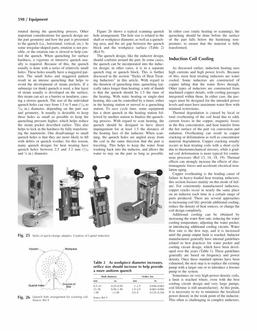
rotated during the quenching process. Otherimportant considerations for quench design arethe part geometry and how the part is presentedto the quench (i.e., horizontal, vertical, etc.). Insome irregular-shaped parts, rotation is not pos-sible, or the rotation rate is slowed to help con-trol the quench. When quenching for surfacehardness, a vigorous or intensive quench usu-ally is required. Because of this, the quenchusually is done with a series of relatively smallholes. These holes usually have a staggered pat-tern. The small holes and staggered patternresult in an intense quenching that helps toavoid the development of steam pockets. If asubmerge (or dunk) quench is used, a fine layerof steam usually is developed on the surface;this steam can act as a barrier or insulator, caus-ing a slower quench. The size of the individualquench holes can vary from 1.5 to 5 mm (1=16 to3=16 in.) diameter, depending on the part sizeand geometry. It usually is desirable to keepthese holes as small as possible to keep thequenching pressure higher, which helps reducethe steam pocket described earlier. This alsohelps to lock in the hardness by fully transform-ing the martensite. One disadvantage to smallquench holes is that they are more likely to fillwith debris or quench residue; for this reason,many quench designs for heat treating havequench holes between 2.5 and 3.2 mm (3=32and ⅛ in.) diameter.
Figure 26 shows a typical scanning quenchhole arrangement. The hole size is related to theshaft or workpiece diameter, as well as a quench-ing area, and the air gap between the quenchblock and the workpiece surface (Table 2)(Ref 9).The quench design, like the inductor design,
should conform around the part. In some cases,the quench can be incorporated into the induc-tor design; in other cases, it is in a separatequench ring or quench block. This is furtherdiscussed in the section “Styles of Heat Treat-ing Inductors” in this article. With regard tothe duration of quenching time, quenching typ-ically takes longer than heating; a rule of thumbis that the quench should be 1.5 the time ofthe heating. With static heating or single-shotheating, this can be controlled by a timer, eitherin the heating station or moved to a quenchingstation. To save cycle time, some equipmenthas a short quench in the heating station fol-lowed by another station to finalize the quench-ing process. With regard to scan heating, thequench should be designed to have directimpingement for at least 1.5 the distance ofthe heating face of the inductor. When scan-ning, the quench holes are angled away fromthe coil in the same direction that the part istraveling. This helps to keep the water fromwashing back into the inductor, and allows thewater to stay on the part as long as possible.
In either case (static heating or scanning), thequenching should be done before the surfaceof the part falls below the hardening tem-perature, to ensure that the material is fullytransformed.
Induction Coil Cooling
As discussed earlier, induction heating useshigh currents and high power levels. Becauseof this, most heat treating inductors are watercooled. Some inductors are constructed ofcopper tubing that the water flows through.Other types of inductors are constructed frommachined copper details, with cooling passagesintegrated within them. In either case, the pas-sages must be designed for the intended powerlevels and must have maximum water flow withminimal restrictions.Thermal degradation is caused by local or
total overheating of the coil head due to eddycurrent losses in the copper, magnetic lossesin the flux concentrator, and heat transfer fromthe hot surface of the part via convection andradiation. Overheating can result in coppercracking or deformation as well as concentratormaterial degradation. Copper cracking usuallyoccurs in heat treating coils with a short cycledue to thermomechanical stresses, while a grad-ual coil deformation is more typical for contin-uous processes (Ref 13, 14, 18, 19). Thermaleffects can strongly increase the effects of elec-tromagnetic forces and accelerate electrical insu-lation aging.Copper overheating is the leading cause of
failure in heavy-loaded heat treating inductors;this section focuses mainly on this mode of fail-ure. For consistently manufactured inductors,copper cracks occur in nearly the same placeon an inductor each time in a certain range ofparts produced. There are several approachesto increasing coil life: provide additional cooling,reduce the density of heat sources, or change thecoil design completely.Additional cooling can be obtained by
increasing the water flow rate, reducing the watercooling temperature, adjusting the water pocket,or introducing additional cooling circuits. Waterflow rate is the first step, and it is increaseduntil the pump output limit is reached. Inductormanufacturers generally have internal guidelinesrelated to best practices for water pocket andcooling circuit design, which have been devel-oped over the years (Table 1). These guidelinesgenerally are based on frequency and powerdensity. Once these standard options have beenexhausted, the next step is to replace the existingpump with a larger one or to introduce a boosterpump to the system.Sometimes on very high-power-density coils,
a limit is reached where, even with the bestcooling circuit design and very large pumps,coil lifetime is still unsatisfactory. At this point,it is necessary to try to minimize the localizedpower density in the weak point of the inductor.This often is challenging in complex inductors,
Fig. 25 Styles of quick-change adapters. Courtesy of Capital Induction
Fig. 26 Quench hole arrangement for scanning coil.Source: Ref 9
Table 2 As workpiece diameter increases,orifice size should increase to help providea more uniform quench
Shaft diameter Orifice size
mm in. mm in.
6.5–13 0.25–0.50 1–1.5 0.046–0.06313–38 0.50–1.50 1.5–2.5 0.063–0.094>38 >1.50 3.5–4 0.125–0.156
Source: Ref 9
598 / Equipment

because changing this section may have someeffect on the heat pattern in this area of the part,as well as in the rest of the part.To determine what high power density is, it is
important to consider the cause of the failure.The failure mode that can be resolved with watercooling in high-power induction heat treatingcoils is mechanical fatigue caused by thermalcycling. During each heat treating cycle, thecopper temperature rises as the power is turnedon, primarily due to current in the induction coil.As the copper temperature increases, the copperexpands. When the power is turned off, the cop-per rapidly cools and contracts.Because the eddy currents are distributed non-
uniformly in the copper cross section, the tem-perature distribution in the copper coil is alsononuniform. Water in the induction coil removesheat through forced convection. This means thatthe rate of heat removal is directly proportionalto the heat-transfer coefficient and the tempera-ture difference between the copper and the bulkwater. The heat-transfer coefficient depends onthe velocity of the water, the pressure of thewater (in addition to the effect of pressure onwater flow), and the temperature of the water.In recent years, computer simulation has pro-
ven an effective tool for estimating thermalcycles in induction coils during a heat treatingprocess (Ref 19–21). These recent studies weremade using some combination of electromag-netic, thermal, and fluid dynamics codes or cor-relations. With this method, the temperaturesthat are the source of the dimensional movementand stress are predicted. Certain guidelines formaximum allowable temperatures are used toensure good life. It is envisioned that in thefuture, these codes could be coupled with struc-tural, stress, and distortion simulation.
Case Study: Single-Shot Coil CopperTemperature Prediction
Acase study using computer simulation to showtypical temperature distributions in a single-shotinduction hardening coil is discussed in this sec-tion. Flux 2D is used for electromagnetic andthermal simulation, and analytical calculationsare made for the heat-transfer coefficients. Theinfluence of pressure (high and low), wall thick-ness (1, 1.5, and 3 mm, or 0.048, 0.062, and0.125 in.), current in the coil (5,000, 7,500, and10,000A), and frequency (1, 3, and 10 kHz) is con-sidered. The correlations for heat-transfer coeffi-cient hold only to approximately 250 �C (480 �F)on the interface of the copper wall with the coolingwater, so if this consideration is not met, the tem-perature in the coil will be less accurate.The geometry for the study is a 19 mm
(3/4 in.) square copper tube with Fluxtrol A mag-netic flux concentrator for heating of a 38 mm(1.5 in.) diameter shaft. The coupling gap usedfor the study is 3.2 mm (⅛ in.). To limit thenumber of variables, the part is not simulatedduring the study. The part is approximated by
a nonmagnetic layer 6.3 mm (¼ in.) thick, withthe properties of steel above the Curie point andthe 25 mm (1 in.) diameter core, which has theproperties of cold low-carbon steel.Figure 27 shows the temperature distribution
in the coil cross section if the current is 5000 Aat 10 kHzwith low pressure and a wall thicknessof 1 mm (0.048 in.) after 10 s of heating. Thetemperature is highest in the corners of the heatface and somewhat lower in the center of the turn.The concentrator is at a significantly lower tem-perature, and the localized higher-temperatureareas are due to conduction through the glue tothe concentrator. The maximum temperature is117 �C (243 �F). Figure 28 shows the tempera-tures in the corner and center of the tube versustime for this case. Nearly the entire temperaturerise in the copper occurs in the first 2 s.If pressure is doubled, the temperature distri-
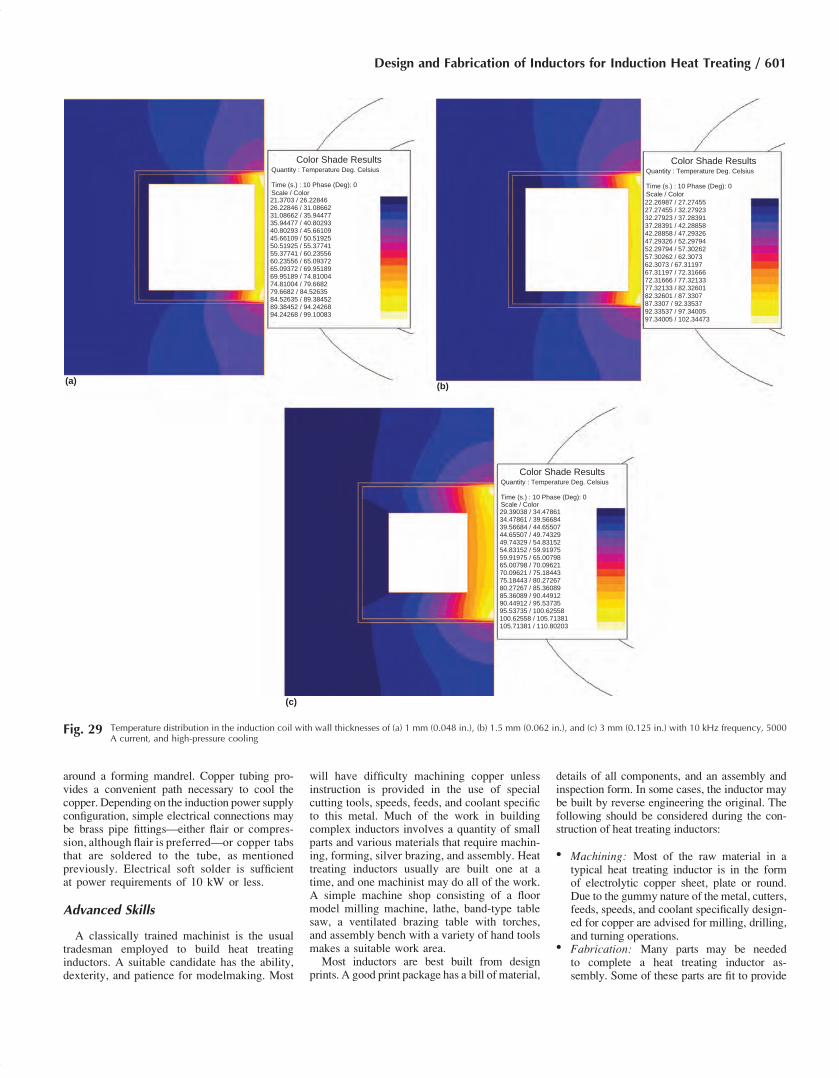
bution is that shown in Fig. 29(a). The maxi-mum temperature in the corner is reducedto 99 �C (210 �F). The difference between thetemperature in the corner of the copper and thecenter of the heat face is significantly higher.Figure 29(b) shows the temperature distributionif the wall thickness is increased to 1.5 mm(0.062 in.). The maximum copper temperatureis slightly higher, 102 �C (216 �F). If the wallthickness is increased to 3 mm (0.125 in.), themaximum temperature increases to approxi-mately 111 �C (232 �F) (Fig. 29c).All of these temperatures are what could
be considered reasonable, and a long copper
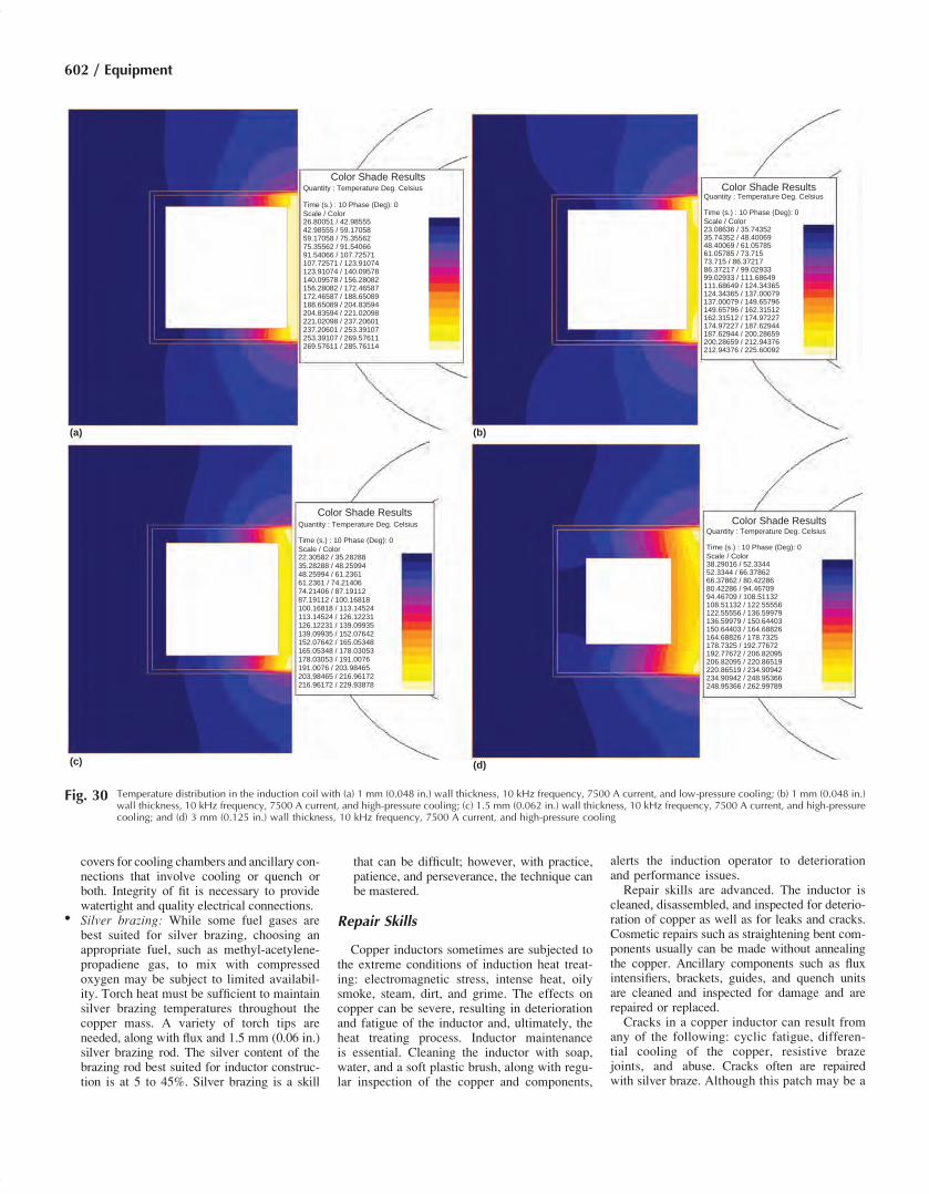
lifetime would be expected based on the tem-peratures. If the current is increased to 7500 A,the differences between the results are muchmore apparent. Figure 30 shows the tempera-ture distributions for the same cases shown inFig. 27 and 29 with the higher current. Nowthe temperature of the copper wall contactingthe water for the low-pressure, 1 mm (0.048 in.)wall (Fig. 30a) is above the threshold where thecorrelations hold. This means that there is dangerof vapor blanket formation and very short coillifetime. It also is important to note that themaximum temperature shifts to the center ofthe tube instead of the corners. This is a sign thatthere is insufficient cooling, and increasing thewater pressure can significantly increase thecoil lifetime.When pressure is increased, the temperature
on the internal walls of the copper tubingdrops to manageable levels (Fig. 30b). The max-imum temperature again is in the corners of thecopper tube instead of the center. However, thelevel of the copper temperature in the cornersremains elevated (225 �C, or 437 �F). For thethicker walls, the temperatures are 230 and 263 �C(446 and 505 �F), respectively (Fig. 30c, d).This means that in each cycle, the copper in the
corners of the tubing expands more than twice asmuch as for the case of the lower current. Whenpower is turned off, the tubing contracts to itsoriginal shape. At these temperatures, there isthe potential that the coil lifetime may not besatisfactory.
Color Shade Results
Quantity : Temperature Deg. Celsius
Time (s.) : 10 Phase (Deg): 0
Scale / Color
22.72733 / 28.59668
28.59668 / 34.46604
34.46604 / 40.3354
40.3354 / 46.20475
46.20475 / 52.0741
52.0741 / 57.94347
57.94347 / 63.81282
63.81282 / 69.68217
69.68217 / 75.55153
75.55153 / 81.42089
81.42089 / 87.29025
87.29025 / 93.1596
93.1596 / 99.02896
99.02896 / 104.89832
104.89832 / 110.76767
110.76767 / 116.63702
Fig. 27 Temperature distribution in the induction coil with 1 mm (0.048 in.) wall thickness, 10 kHz frequency, 5000 Acurrent, and low-pressure cooling
Design and Fabrication of Inductors for Induction Heat Treating / 599

If frequency is reduced but the current re-mains 7500 A, the coil temperatures are reducedsignificantly (Fig. 31). For the case of the 1 mm(0.048 in.) wall with low pressure, the maximumtemperature is reduced to 178 �C (352 �F)(Fig. 31a). The temperature in the corners issignificantly lower than in the center. If pres-sure is increased, the copper temperature isreduced to 133 �C (271 �F) (Fig. 31b). How-ever, the maximum temperature is still in thecentral sections of the copper rather thanthe corners. This is due to the wall thicknessof the copper being less than optimal (1.6d).The low copper thickness increases resistanceand losses in the central section of the coil.When the wall thickness is increased to
1.5 mm (0.062 in.), the copper temperature isreduced to 114 �C (237 �F) (Fig. 31c). Thecentral temperature of the winding also isreduced relative to the corners. The maximumin temperature lies just inside the edge of thewater cooling, implying slightly less than opti-mal wall thickness. For the case of the 3 mm(0.125 in.) wall, the maximum temperaturegoes up again to 125 �C (257 �F) (Fig. 31d).The maximum now is clearly in the corners.The temperature in the center of the tubeactually is lower for this case. The rise in max-imum temperature is due to it being a fartherdistance from the water cooling.The losses in the copper tubing are nearly the
same for these two cases (3 kHz; 1.5 and 3 mm,or 0.062 and 0.125 in., wall thickness) and justunder 20% lower than for the 1 mm (0.048 in.)wall thickness. The optimal wall thickness andhence the maximum current-carrying capacity for3 kHz would lie between these two thicknesses.At 1 kHz, 10,000 A was used for compari-
son, because at lower frequencies it is naturalto have higher currents (Fig. 32). For the1 mm (0.048 in.) wall thickness and low pres-sure, temperature in the copper clearly is exces-sive, and there is a significant gradient from thecenter to the corners (Fig. 32a). As pressure is
increased, the temperature is marginal (230 �C,or 446 �F, wall temperature), and there is stilla significant gradient from center to edge(Fig. 32b). This is because the wall thicknessis significantly less than optimal.For the 1.5 mm (0.062 in.) wall thickness, the
maximum temperature declines to approxi-mately 144 �C (291 �F) (Fig. 32c). Losses inthe copper are nearly 40% lower than for the1 mm (0.048 in.) wall thickness. The tempera-ture distribution across the face is nearly flat,implying that the wall thickness is less thanoptimal. For the 3 mm (0.125 in.) wall thick-ness, the maximum temperature is only 100 �C(212 �F), and the location is the corners(Fig. 32d). The losses in the 3 mm (0.125 in.)wall thickness are approximately 30% lowerthan for the 1.5 mm (0.062 in.) wall thickness.Another factor related to water cooling of
induction coils is the water temperature. Thetemperature of the induction coil is influencedin two ways by the water temperature. It is clearthat the lower the water temperature, the coolerthe induction coil, because the cooling methodis convection. If the water temperature waslowered by 10 �C (18 �F), then it would beexpected that the maximum temperature in thecopper also would be 10 �C (18 �F) lower.Because the temperature change (DT) of the
copper would be the same, one would expectthat the magnitude of the copper movementwould be the same, and coil lifetime would bealso. However, this is not true, because thecoefficient of thermal expansion of copper isnot constant with temperature (Fig. 33). Astemperature rises, the coefficient of thermalexpansion of copper continues to rise (Ref 22).This means that the higher the temperature, thelarger the movement for the same DT.In reality, the DT of the copper is not the
same. It actually is slightly less, because the cop-per electrical resistivity rises with temperature.Therefore, the losses in the copper are lower,and the resulting DT smaller. This overrides the
fact that the heat-transfer coefficient of water isslightly lower at lower temperature (Ref 23).The last factor to consider with water cooling
of inductors is the water quality. The best fluidfor cooling induction coils in heat treatingapplications is pure, demineralized water. Purewater has a naturally high heat-transfer coeffi-cient. Almost all additives have a negativeeffect on the heat-transfer capability.Minerals are especially bad. Over time, they
tend to fall out of solution and build up on thewall of the copper tubing. This has two nega-tive effects. First, the mineral layer reducesthe cross section for water flow. The minerallayer also creates a barrier for heat transfer,causing the temperature of the copper to rise.If water containing minerals is used, over timethe copper temperature continues to rise andreach a critical level, resulting in an inductorfailure. With this type of cooling fluid, theinduction coil must be cleaned and flushed ona regular interval.
Styles of Heat Treating Inductors
As stated previously, induction heat treatingcoils come in many shapes and sizes. An excel-lent source for photos of induction heat treat-ing coils is the book Practical Induction HeatTreating by Richard Haimbaugh (Ref 5). Thesephotos are included in Steel Heat Treating Fun-damentals and Processes, Volume 4A of ASMHandbook, 2013, so they are not repeated here.
Skills for Heat Treating InductorConstruction
Copper is a unique metal associated withan ancient skills trade—coppersmithing. Whiletraining as either a craftsman or an artisan, astudent coppersmith would apprentice under ajourneyman to learn the character and manipu-lation of this metal. Although the United Stateshas assimilated the coppersmith into other skilledtrades, coppersmithing is still a recognized tradethroughout the industrialized world.The tools and skills of a coppersmith are ide-
ally matched to the metal; however, is a copper-smith by trade needed to build a copperinductor? The answer is no; yet, the skills of acoppersmith must be learned in the process ofbuilding heat treating inductors, along with afamiliarity of high-power electrical circuits.
Basic Skills
Because copper has a characteristic of beingeasily formed into complex shapes, a craftsmanhandy with tools, a soldering iron, and a propanetorch is able to build a good basic inductor. Inthe process of forming, copper work hardens;yet, when heated to a dull red and quenched inwater, it again forms easily. Basic inductors aremade of readily available copper tubing wound
Fig. 28 Temperature dynamics during heating at critical points with 1 mm (0.048 in.) wall thickness, 10 kHz frequency,5000 A current, and high-pressure cooling
600 / Equipment
around a forming mandrel. Copper tubing pro-vides a convenient path necessary to cool thecopper. Depending on the induction power supplyconfiguration, simple electrical connections maybe brass pipe fittings—either flair or compres-sion, although flair is preferred—or copper tabsthat are soldered to the tube, as mentionedpreviously. Electrical soft solder is sufficientat power requirements of 10 kW or less.
Advanced Skills
A classically trained machinist is the usualtradesman employed to build heat treatinginductors. A suitable candidate has the ability,dexterity, and patience for modelmaking. Most
will have difficulty machining copper unlessinstruction is provided in the use of specialcutting tools, speeds, feeds, and coolant specificto this metal. Much of the work in buildingcomplex inductors involves a quantity of smallparts and various materials that require machin-ing, forming, silver brazing, and assembly. Heattreating inductors usually are built one at atime, and one machinist may do all of the work.A simple machine shop consisting of a floormodel milling machine, lathe, band-type tablesaw, a ventilated brazing table with torches,and assembly bench with a variety of hand toolsmakes a suitable work area.Most inductors are best built from design
prints. A good print package has a bill of material,
details of all components, and an assembly andinspection form. In some cases, the inductor maybe built by reverse engineering the original. Thefollowing should be considered during the con-struction of heat treating inductors:
� Machining: Most of the raw material in atypical heat treating inductor is in the formof electrolytic copper sheet, plate or round.Due to the gummy nature of the metal, cutters,feeds, speeds, and coolant specifically design-ed for copper are advised for milling, drilling,and turning operations.
� Fabrication: Many parts may be neededto complete a heat treating inductor as-sembly. Some of these parts are fit to provide
Color Shade ResultsQuantity : Temperature Deg. Celsius
Time (s.) : 10 Phase (Deg): 0
Scale / Color21.3703 / 26.2284626.22846 / 31.0866231.08662 / 35.9447735.94477 / 40.8029340.80293 / 45.6610945.66109 / 50.5192550.51925 / 55.3774155.37741 / 60.2355660.23556 / 65.0937265.09372 / 69.9518969.95189 / 74.8100474.81004 / 79.668279.6682 / 84.5263584.52635 / 89.3845289.38452 / 94.2426894.24268 / 99.10083
Color Shade ResultsQuantity : Temperature Deg. Celsius
Time (s.) : 10 Phase (Deg): 0
Scale / Color
22.26987 / 27.27455
27.27455 / 32.27923
32.27923 / 37.28391
37.28391 / 42.28858
42.28858 / 47.29326
47.29326 / 52.29794
52.29794 / 57.30262
57.30262 / 62.3073
62.3073 / 67.31197
67.31197 / 72.31666
72.31666 / 77.32133
77.32133 / 82.32601
82.32601 / 87.3307
87.3307 / 92.33537
92.33537 / 97.34005
97.34005 / 102.34473
Color Shade ResultsQuantity : Temperature Deg. Celsius
Time (s.) : 10 Phase (Deg): 0Scale / Color29.39038 / 34.4786134.47861 / 39.5668439.56684 / 44.6550744.65507 / 49.7432949.74329 / 54.8315254.83152 / 59.9197559.91975 / 65.0079865.00798 / 70.0962170.09621 / 75.1844375.18443 / 80.2726780.27267 / 85.3608985.36089 / 90.4491290.44912 / 95.5373595.53735 / 100.62558100.62558 / 105.71381105.71381 / 110.80203
(a) (b)
(c)
Fig. 29 Temperature distribution in the induction coil with wall thicknesses of (a) 1 mm (0.048 in.), (b) 1.5 mm (0.062 in.), and (c) 3 mm (0.125 in.) with 10 kHz frequency, 5000A current, and high-pressure cooling
Design and Fabrication of Inductors for Induction Heat Treating / 601
covers for cooling chambers and ancillary con-nections that involve cooling or quench orboth. Integrity of fit is necessary to providewatertight and quality electrical connections.
� Silver brazing: While some fuel gases arebest suited for silver brazing, choosing anappropriate fuel, such as methyl-acetylene-propadiene gas, to mix with compressedoxygen may be subject to limited availabil-ity. Torch heat must be sufficient to maintainsilver brazing temperatures throughout thecopper mass. A variety of torch tips areneeded, along with flux and 1.5 mm (0.06 in.)silver brazing rod. The silver content of thebrazing rod best suited for inductor construc-tion is at 5 to 45%. Silver brazing is a skill
that can be difficult; however, with practice,patience, and perseverance, the technique canbe mastered.
Repair Skills
Copper inductors sometimes are subjected tothe extreme conditions of induction heat treat-ing: electromagnetic stress, intense heat, oilysmoke, steam, dirt, and grime. The effects oncopper can be severe, resulting in deteriorationand fatigue of the inductor and, ultimately, theheat treating process. Inductor maintenanceis essential. Cleaning the inductor with soap,water, and a soft plastic brush, along with regu-lar inspection of the copper and components,
alerts the induction operator to deteriorationand performance issues.Repair skills are advanced. The inductor is
cleaned, disassembled, and inspected for deterio-ration of copper as well as for leaks and cracks.Cosmetic repairs such as straightening bent com-ponents usually can be made without annealingthe copper. Ancillary components such as fluxintensifiers, brackets, guides, and quench unitsare cleaned and inspected for damage and arerepaired or replaced.Cracks in a copper inductor can result from
any of the following: cyclic fatigue, differen-tial cooling of the copper, resistive brazejoints, and abuse. Cracks often are repairedwith silver braze. Although this patch may be a
Color Shade ResultsQuantity : Temperature Deg. Celsius
Time (s.) : 10 Phase (Deg): 0
Scale / Color26.80051 / 42.9855542.98555 / 59.1705859.17058 / 75.3556275.35562 / 91.5406691.54066 / 107.72571107.72571 / 123.91074123.91074 / 140.09578140.09578 / 156.28082156.28082 / 172.46587172.46587 / 188.65089188.65089 / 204.83594204.83594 / 221.02098221.02098 / 237.20601237.20601 / 253.39107253.39107 / 269.57611269.57611 / 285.76114
Color Shade ResultsQuantity : Temperature Deg. Celsius
Time (s.) : 10 Phase (Deg): 0
Scale / Color23.08636 / 35.7435235.74352 / 48.4006948.40069 / 61.0578561.05785 / 73.71573.715 / 86.3721786.37217 / 99.0293399.02933 / 111.68649111.68649 / 124.34365124.34365 / 137.00079137.00079 / 149.65796149.65796 / 162.31512162.31512 / 174.97227174.97227 / 187.62944187.62944 / 200.28659200.28659 / 212.94376212.94376 / 225.60092
Color Shade Results
(a) (b)
(d)(c)
Quantity : Temperature Deg. Celsius
Time (s.) : 10 Phase (Deg): 0
Scale / Color22.30582 / 35.2828835.28288 / 48.2599448.25994 / 61.236161.2361 / 74.2140674.21406 / 87.1911287.19112 / 100.16818100.16818 / 113.14524113.14524 / 126.12231126.12231 / 139.09935139.09935 / 152.07642152.07642 / 165.05348165.05348 / 178.03053178.03053 / 191.0076191.0076 / 203.98465203.98465 / 216.96172216.96172 / 229.93878
Color Shade ResultsQuantity : Temperature Deg. Celsius
Time (s.) : 10 Phase (Deg): 0
Scale / Color38.29016 / 52.334452.3344 / 66.3786266.37862 / 80.4228680.42286 / 94.4670994.46709 / 108.51132108.51132 / 122.55556122.55556 / 136.59979136.59979 / 150.64403150.64403 / 164.68826164.68826 / 178.7325178.7325 / 192.77672192.77672 / 206.82095206.82095 / 220.86519220.86519 / 234.90942234.90942 / 248.95366248.95366 / 262.99789
Fig. 30 Temperature distribution in the induction coil with (a) 1 mm (0.048 in.) wall thickness, 10 kHz frequency, 7500 A current, and low-pressure cooling; (b) 1 mm (0.048 in.)wall thickness, 10 kHz frequency, 7500 A current, and high-pressure cooling; (c) 1.5 mm (0.062 in.) wall thickness, 10 kHz frequency, 7500 A current, and high-pressurecooling; and (d) 3 mm (0.125 in.) wall thickness, 10 kHz frequency, 7500 A current, and high-pressure cooling
602 / Equipment

cost-effective repair, it is seldom permanent. Ina robust process, the copper inductor should bereplaced at an appropriate time/life interval.
Attachment of Magnetic FluxControllers
It has been explained that flux controllers areneeded to direct the current flow for specificinduction heating applications. Attaching themto the inductor requires careful handling sothat they are properly placed and secure.
Misplacement or loss of any portion of amagneticflux controller may result in a nonconformingprocessed part. Magnetic flux controllers are fre-quency dependent and made from either a siliconsteel, soft magnetic ferrite, or a soft magneticcomposite. Attaching these materials to an induc-tor can present a challenge to the designer/builder.The following are a few examples.
Silicon Steel Laminations
This material is supplied in a variety ofgrades, thicknesses, and finishes. Its usual formis a thin sheet with an insulating layer on both
sides. It is first designed to a specific shape, thendie stamped or machined and to fit the inductor.The most common shape is a rectangular orsquare “C” form. The laminations are stackedside by side onto the inductor in such a way asto expose that portion of the copper to the partbeing heated. Copper tabs of the same shapeare silver brazed onto the inductor at variousintervals in order to support the stack. Securingthe stack is achieved by either gluing with ahigh-temperature epoxy or by mechanicallyclamping it to the inductor. Various clampingmethods are used. The most common is theuse of a semirigid glass epoxy circuit board
(a) (b)
(d)(c)
Color Shade ResultsQuantity : Temperature Deg. Celsius
Time (s.) : 10 Phase (Deg): 0
Scale / Color23.992 / 33.64118
33.64118 / 43.29035
43.29035 / 52.93953
52.93953 / 62.58871
62.58871 / 72.23788
72.23788 / 81.88705
81.88705 / 91.53623
91.53623 / 101.18541
101.18541 / 110.83459
110.83459 / 120.48376
120.48376 / 130.13293
130.13293 / 139.78212
139.78212 / 149.43129
149.43129 / 159.08047
159.08047 / 168.72964
168.72964 / 178.37881
Color Shade Results
Quantity : Temperature Deg. Celsius
Time (s.) : 10 Phase (Deg): 0
Scale / Color
21.77783 / 28.7492
28.7492 / 35.72057
35.72057 / 42.69193
42.69193 / 49.6633
49.6633 / 56.63467
56.63467 / 63.60603
63.60603 / 70.5774
70.5774 / 77.54877
77.54877 / 84.52013
84.52013 / 91.4915
91.4915 / 98.46287
98.46287 / 105.43423
105.43423 / 112.4056
112.4056 / 119.37697
119.37697 / 126.34834
126.34834 / 133.3197
Color Shade ResultsQuantity : Temperature Deg. Celsius
Time (s.) : 10 Phase (Deg): 0
Scale / Color
22.64523 / 28.33354
28.33354 / 34.02185
34.02185 / 39.71016
39.71016 / 45.39847
45.39847 / 51.08678
51.08678 / 56.77509
56.77509 / 62.46339
62.46339 / 68.1517
68.1517 / 73.84001
73.84001 / 79.52832
79.52832 / 85.21663
85.21663 / 90.90494
90.90494 / 96.59325
96.59325 / 102.28156
102.28156 / 107.96986
107.96986 / 113.65817
Color Shade ResultsQuantity : Temperature Deg. Celsius
Time (s.) : 10 Phase (Deg): 0
Scale / Color
29.76266 / 35.69722
35.69722 / 41.63177
41.63177 / 47.56632
47.56632 / 53.50088
53.50088 / 59.43542
59.43542 / 65.36998
65.36998 / 71.30453
71.30453 / 77.23909
77.23909 / 83.17365
83.17365 / 89.10819
89.10819 / 95.04275
95.04275 / 100.9773
100.9773 / 106.91185
106.91185 / 112.84641
112.84641 / 118.78096
118.78096 / 124.71552
Fig. 31 Temperature distribution in the induction coil with (a) 1 mm (0.048 in.) wall thickness, 3 kHz frequency, 7500 A current, and low-pressure cooling; (b) 1 mm (0.048 in.)wall thickness, 3 kHz frequency, 7500 A current, and high-pressure cooling; (c) 1.5 mm (0.062 in.) wall thickness, 3 kHz frequency, 7500 A current, and high-pressurecooling; and (d) 3 mm (0.125 in.) wall thickness, 3 kHz frequency, 7500 A current, and high-pressure cooling
Design and Fabrication of Inductors for Induction Heat Treating / 603

material, such as G-10, that is cut and fit tothe back of the stack and is fastened at both ends.It is practical to stack laminations aroundthe outside or inside of an inductor loop. Installedonto circular inductors, the laminations radiatefrom the center point, leaving noticeable gaps,especially on small, circular inductors; yet, withcareful design, this can be minimized.
Soft Magnetic Composites andSintered Ferrites
These products are engineered and manufac-tured for specific induction applications. Because
sintered ferrites are brittle and difficult tomachine, their use mainly has been limited totransformer applications. Soft magnetic compo-sites, however, have been designed specificallyfor the induction heating industry. These productsare engineered to be used at the common power-supply frequencies. They are manufactured invarious block sizes, are easily machined, andfit to the inductor. Both iron ferrites andsoft magnetic composites are attached to theinductor, either mechanically with bolts andscrews or with glue. The product literaturedescribes their use in induction heating applica-tions (Ref 13).
Integrity Procedures prior toProduction
This section includes discussion on flux andoxide removal, leak and flow checking, silverplating, and electrical parameter measurement.
Flux and Oxide Removal
After brazing, the induction coil copper has fluxnear the braze joints, along with oxidation fromthe high-temperature brazing process. Prior toassembly, the flux and oxides should be removed.
(a) (b)
(d)(c)
Color Shade ResultsQuantity : Temperature Deg. Celsius
Time (s.) : 10 Phase (Deg): 0
Scale / Color
28.14111 / 49.29983
49.29983 / 70.45855
70.45855 / 91.61726
91.61726 / 112.77598
112.77598 / 133.93469
133.93469 / 155.0934
155.0934 / 176.25212
176.25212 / 197.41084
197.41084 / 218.56955
218.56955 / 239.72827
239.72827 / 260.88699
260.88699 / 282.04572
282.04572 / 303.20441
303.20441 / 324.36313
324.36313 / 345.52185
345.52185 / 366.68057
Color Shade ResultsQuantity : Temperature Deg. Celsius
Time (s.) : 10 Phase (Deg): 0
Scale / Color
23.12088 / 36.80721
36.80721 / 50.49354
50.49354 / 64.17987
64.17987 / 77.8662
77.8662 / 91.55252
91.55252 / 105.23886
105.23886 / 118.92519
118.92519 / 132.61151
132.61151 / 146.29784
146.29784 / 159.98418
159.98418 / 173.6705
173.6705 / 187.35683
187.35683 / 201.04317
201.04317 / 214.72949
214.72949 / 228.41582
228.41582 / 242.10214
Color Shade ResultsQuantity : Temperature Deg. Celsius
Time (s.) : 10 Phase (Deg): 0
Scale / Color
23.82666 / 31.32733
31.32733 / 38.8271
38.8271 / 46.32866
46.32866 / 53.82932
53.82932 / 61.32999
61.32999 / 68.83066
68.83066 / 76.33132
76.33132 / 83.83199
83.83199 / 91.33265
91.33265 / 98.83332
98.83332 / 106.33398
106.33398 / 113.83465
113.83465 / 121.33532
121.33532 / 128.83597
128.83597 / 136.33664
136.33664 / 143.83731
Color Shade Results
Quantity : Temperature Deg. Celsius
Time (s.) : 10 Phase (Deg): 0
Scale / Color
29.53604 / 34.54433
34.54433 / 39.5526
39.5526 / 44.56089
44.56089 / 49.56918
49.56918 / 54.57746
54.57746 / 59.58574
59.58574 / 64.59402
64.59402 / 69.60231
69.60231 / 74.6106
74.6106 / 79.61887
79.61887 / 84.62716
84.62716 / 89.63544
89.63544 / 94.64372
94.64372 / 99.65201
99.65201 / 104.66029
104.66029 / 109.66858
Fig. 32 Temperature distribution in the induction coil with (a) 1 mm (0.048 in.) wall thickness, 1 kHz frequency, 10,000 A current, and low-pressure cooling; (b) 1 mm (0.048 in.)wall thickness, 1 kHz frequency, 10,000 A current, and high-pressure cooling; (c) 1.5 mm (0.062 in.) wall thickness, 1 kHz frequency, 10,000 A current, and high-pressurecooling; and (d) 3 mm (0.125 in.) wall thickness, 1 kHz frequency, 10,000 A current, and high-pressure cooling
604 / Equipment

The first step in the process is to place theinduction coil under hot (70 to 80 �C, or 150 to180 �F) running water. Hot water helps toremove the bulk of the flux remaining from thebrazing process. It also is recommended to flowthe hot water through the water-cooling passagesof the inductor to remove flux that could be builtup on the inside of the tube and obstructing thepassage.After the hot water cleaning, the next step
in the process is to sandblast the inductor toremove the oxides. The sandblasting processalso removes the remaining flux from the induc-tor. After sandblasting, a fine glass beading pro-cess should be used to improve the surfacecondition of the inductor.After glass beading, the copper is clean. If left
this way, the inductor oxidizes in air and changecolor. It is good practice to spray the surface ofthe induction coil (with the exception of theelectrical contacts) with a clear coat varnish.The varnish inhibits copper oxidation.In some cases with heavily loaded heat treat-
ing inductors, a low-temperature tempering at200 �C (400 �F) for several hours or a higher-temperature annealing process in air is per-formed. This tempering process removes thestresses from manufacturing and oxidizes thecopper to a dark orange (tempering) or a darkbrown (annealing). From this state, the copperdoes not oxidize further, and it is not necessaryto apply a clear coat varnish.
Leak and Flow Checking
After cleaning the induction coil, it is neces-sary to ensure that it is leaktight and that thewater passages are not clogged. Leak checkingof the induction coil typically is done by sub-merging the induction coil in a tank of water
and applying high-pressure shop air. The testshould be conducted for several minutes. Ifbubbles appear, the coil must be sent back to thecoil builder to repair the leak. In some specialatmosphere heat treating applications, a waterleak is especially dangerous. In these instances,helium leak checking should be performed.After leak checking, the induction coil
should be connected to water lines. With a spe-cific pressure applied, the flow rate of the waterthrough the induction coil should be measured.For every induction coil, a minimum flow rateshould be defined. If the flow rate does not meetthis minimum level, it means that the coolingchannel is obstructed. The obstruction must beremoved before the induction coil can beshipped; therefore, the induction coil shouldbe sent back to the coil builder.
Silver Plating
Silver plating of the induction coil contactstypically is done after cleaning. The main roleof silver plating is to act as a corrosion inhibitorfor the electrical contacts. Corrosion increasesthe contact resistance and can lead to prematureinduction coil failure.Silver plating materials can come in liquid,
paste, or powder form. Liquid silver plating solu-tion from HM Products Inc. is most commonlyused in the trade. The solution is either brushedor rubbed onto the contact area. After application,the contact area is flushed with water. If the sur-face is not flushedwithwater shortly after applica-tion, the silver carrier corrodes the contacts, and agreen oxide formation occurs. Care should betaken while using the silver plating materials,because most of them contain sodium cyanide,which is a toxic material.
Electrical Parameter Measurement
On some induction coils, such as cast orpotted inductors, it is not possible to physicallysee or mechanically inspect all of the criticaldimensions of the induction coil. Also, on induc-tion coils with magnetic flux controllers, it is notpractical to count the number of laminations, orit may be difficult to determine if the correct softmagnetic composite material grade was used.To ensure that the induction coil perfor-
mance is consistent with other induction coilsbuilt to that print, coil electrical parameter mea-surements should be made prior to shipping.The best inspection method involves measur-ing the inductance or impedance and the resis-tance of the induction coil with the componentit is designed to heat at the frequency of theheating. If this is not possible, valuable informa-tion can be obtained about the coil consistencyfrom a measurement of the inductance withouta part.Devices capable of measuring coil inductance
or impedance and resistance (LCR meters) at aselectable frequency typically cost several thou-sand dollars and are available from a numberof manufacturers. For inductance measurementonly, less-expensive devices are available. Atthe time of this writing, one such device thatworks well, the L/C Meter IIB, is manufacturedby Almost All Digital Electronics and costsunder $200 (Ref 24). Over time, new deviceswill come to the market with even better charac-teristics for induction coil quality control.
REFERENCES
1. A. Muhlbauer, History of Induction Heat-ing and Melting, Vulcan Verlag GmbH,Huyssenallee, Essen, Germany, 2008
2. H.B. Osborne, Jr., Induction Heating andHardening, Part A, American Society forMetals, Metals Park, OH, 1977
3. V.P. Vologdin and B.N. Romanov, Devicefor Hardening Crankshafts Using HF Cur-rents, USSR Patent 48416, filed Dec 16,1935, issued 1936
4. V.P. Vologdin, Induction Surface Harden-ing, Oborongiz, Moscow, 1947
5. R.E. Haimbaugh, Practical Induction HeatTreating, ASM International, MaterialsPark, OH, 2001
6. C.A. Tudbury, Basics of Induction Heating,Vol 1, John F. Rider, New York, NY, 1960
7. S.L. Semiatin and D.E. Stutz, InductionHeat Treatment of Steel, American Societyfor Metals, Metals Park, OH, 1986
8. M.G. Lozinskiy, Industrial Applicationsof Induction Heating, Pergamon Press,Oxford, London, New York, 1969
9. V.Rudnev et al.,Handbook of InductionHeat-ing, Marcel Dekker, New York, NY, 2003
10. R.C. Goldstein et al., “Virtual Prototypingof Induction Heat Treating,” 25th ASMHeat Treating Society Conference, Sept14–17, 2009 (Indianapolis, IN)
0
20
200 400
Temperature, K
600 800
15
10
Co
effic
ien
t o
f th
erm
al e
xp
an
sio
n
Thermal expansion of copper data
5
0
Fig. 33 Temperature dependence of the coefficient of thermal expansion of copper. Source: Ref 22
Design and Fabrication of Inductors for Induction Heat Treating / 605

11. J. Cai et al., Integration of Induction HeatTreat Simulation into Manufacturing Cycle,J. Heat Treat. Prog., Vol 3 (No. 2), 2003
12. V.S. Nemkov, Modeling of InductionHardening Processes, Handbook of Ther-mal Process Modeling of Steel, C.H. Gurand J. Pan, Ed., CRC Press, 2009
13. W.I. Stuehr and D. Lynch, “How toImprove Inductor Life,” 23rd ASM HeatTreating Society Conference, Sept 25–28,2005 (Pittsburgh, PA)
14. W.I. Stuehr and D. Lynch, “How toImprove Inductor Life, Part II,” 24th ASMHeat Treating Society Conference, Sept17–19, 2007 (Detroit, MI)
15. Ajax Tocco Magnethermic, http://www.ajaxtocco.com/default.asp?ID=134
16. V.S. Nemkov and R.C. Goldstein, DesignPrinciples for Induction Heating andHardening, Chap. 15, Handbook of Metal-lurgical Process Design, G. Totten, K.Funatani, and L. Xie, Ed., Marcel Dekker,New York, NY, 2004
17. V.S. Nemkov, Resource Guide for InductionHeating, CD-R, Fluxtrol Inc., 2006
18. V.I. Rudnev, Systematic Analysis of Induc-tion Coil Failure, Parts 1–11, Heat Treat.Prog. Mag., Aug 2005–Sept/Oct 2007
19. H. Svendsen and S.T. Hagen, “Thermo-Mechanical Fatigue Life Estimation ofInduction Coils,” International ScientificColloquium onModeling of ElectromagneticProcessing, Oct 27–29, 2008 (Hannover,Germany)
20. R.C. Goldstein and V.S. Nemkov, “Influ-ence of Cooling Conditions on InductionCoil Temperatures,” International Sympo-sium on Heating by Internal Sources(Padua, Italy), 2007
21. H. Svendsen and S.T. Hagen, “TemperatureDistribution in Selected Cross-Sections ofInduction Heating Coils,” InternationalSymposium on Heating by Internal Sources(Padua, Italy), 2007
22. Case Studies in Process Modeling, Engi-neering Statistics Handbook, NIST/SEMATECH, http://www.itl.nist.gov/div898/handbook/pmd/section6/pmd6.htm
23. Fluxtrol, Inc. internal documents24. L/C Meter IIB, Almost All Digital Elec-
tronics, http://aade.com/lcmeter.htm
606 / Equipment