Inductors - UNP · inductors for general purposes to inductors for high frequency applications. TDK...
133
Inductors SMD inductors from TDK, cover a vast array of applications and include inductors for DC power lines, inductors for general purposes to inductors for high frequency applications. TDK offers the highest quality axial coils, chip inductors, radial coils, thin-film chip inductors, shielded coils, multilayer surface mount inductors, power inductors, high-frequency inductors, non-polarized inductors and multilayer chip inductors. Shape/Type Characteristics Series NLU Series MLK Series MLG Series HIGH FREQUENCY NLH Series MLF Series NLV Series SIGNAL LINE NL Series NLCV25 Series NLC Series NLFC Series SLF Series SURFACE MOUNT INDUCTORS POWER LINE LDR Series EL Series SIGNAL LINE ELF Series TSL Series SL Series LEADED INDUCTORS RADIAL POWER LINE ELC Series GENERAL APPLICATIONS SP Series LEADED INDUCTORS AXIAL POWER APPLICATIONS SP Series
-
Upload
trinhnguyet -
Category
Documents
-
view
257 -
download
1
Transcript of Inductors - UNP · inductors for general purposes to inductors for high frequency applications. TDK...

Inductors
SMD inductors from TDK, cover a vast array of applications and include inductors for DC power lines, inductors for general purposes to inductors for high frequency applications. TDK offers the highest quality axial coils, chip inductors, radial coils, thin-film chip inductors, shielded coils, multilayer surface mount inductors, power inductors, high-frequency inductors, non-polarized inductors and multilayer chip inductors.
Shape/Type Characteristics Series NLU Series MLK Series MLG Series HIGH FREQUENCY NLH Series MLF Series NLV Series SIGNAL LINE NL Series
NLCV25 Series NLC Series
NLFC Series SLF Series
SURFACE MOUNT
INDUCTORS
POWER LINE
LDR Series EL Series SIGNAL LINE ELF Series
TSL Series SL Series
LEADED INDUCTORS RADIAL
POWER LINE ELC Series
GENERAL APPLICATIONS SP Series LEADED INDUCTORS AXIAL POWER APPLICATIONS SP Series

Inductors MLF Series MLF1608 Type
For General ApplicationsSMD
FEATURES• High-reliability monolithic structure.
• Ferrite core and magnetic shielding enables the design of com-
pact circuits with high packing density.
• Excellent solderability and high heat resistance permits either
flow or reflow soldering.
APPLICATIONSPersonal computers, HDDs, or other various electronic appliances.
SPECIFICATIONS
RECOMMENDED REFLOW SOLDERING CONDITIONS
PRODUCT IDENTIFICATION
(1) Series name
(2) Dimensions L×W
(3) Material code
(4) Inductance value
(5) Inductance tolerance
(6) Packaging style
PACKAGING STYLE AND QUANTITIES
HANDLING AND PRECAUTIONS• Before soldering, be sure to preheat components.
The preheating temperature should be set so that the tempera-
ture difference between the solder temperature and product
temperature does not exceed 150°C.
• After mounting components onto the printed circuit board, do not
apply stress through board bending or mishandling.
• The inductance value may change due to magnetic saturation if
the current exceeds the rated maximum.
• Do not expose the inductors to stray magnetic fields.
• Avoid static electricity discharge during handling.
• When hand soldering, apply the soldering iron to the printed cir-
cuit board only. Temperature of the iron tip should not exceed
300°C. Soldering time should not exceed 3 seconds.
Operating temperature range –25 to +85°C
Storage temperature range –40 to +85°C[Unit of products]
10s max.
40s max.Preheating 60 to 120s min.
Naturalcooling
220°C200°C
150°C
Time(s)
1608 1.6×0.8mm2012 2.0×1.25mm
47N 47nH[0.047µH]R15 0.15µH1R0 1µH100 10µH
K ±10%M ±20%
T Taping [reel]
Packaging style Product’s thickness QuantityTaping 0.8/0.85mm 4000 pieces/reel
1.25mm 2000 pieces/reel
MLF 1608 A 1R0 K T
(1) (2) (3) (4) (5) (6)
Specifications which provide more details for the proper and safe use of the described product are available upon request.All specifications are subject to change without notice.

Inductors MLF Series MLF1608 Type
For General ApplicationsSMD
SHAPES AND DIMENSIONS/RECOMMENDED PC BOARD PATTERN
ELECTRICAL CHARACTERISTICS
∗ 1 47N means for 47nH (0.047µH).∗ 2 X: Please specify inductance tolerance, M(±20%) or K(±10%).
3±0.2
1.6±0.15
0.8
±0.1
5
2.1
0.7
0.7
0.8
±0.1
5
Dimensions in mmWeight: 4mg
Inductance(µH)
Inductancetolerance
QTestfrequencyL, Q (MHz)
Self-resonantfrequency (MHz)
DC resistance(Ω)
Rated current(mA)max.
ThicknessT (mm)
Part No.min. nom. min. nom. max. nom.
0.047 ±20% 10 20 50 260 350 0.3 0.2 50 0.8 MLF1608D47N∗ 1X∗ 2T0.068 ±20% 10 20 50 250 325 0.3 0.2 50 0.8 MLF1608D68NXT0.082 ±20% 10 20 50 245 310 0.3 0.2 50 0.8 MLF1608D82NXT0.1 ±20, ±10% 15 25 25 240 295 0.5 0.3 50 0.8 MLF1608DR10XT0.12 ±20, ±10% 15 25 25 205 280 0.5 0.3 50 0.8 MLF1608DR12XT0.15 ±20, ±10% 15 25 25 180 260 0.6 0.4 50 0.8 MLF1608DR15XT0.18 ±20, ±10% 15 25 25 165 245 0.6 0.4 50 0.8 MLF1608DR18XT0.22 ±20, ±10% 15 25 25 150 230 0.8 0.45 50 0.8 MLF1608DR22XT0.27 ±20, ±10% 15 25 25 136 210 0.8 0.5 50 0.8 MLF1608DR27XT0.33 ±20, ±10% 15 25 25 125 200 0.85 0.55 35 0.8 MLF1608DR33XT0.39 ±20, ±10% 15 25 25 110 185 1 0.65 35 0.8 MLF1608DR39XT0.47 ±20, ±10% 15 25 25 105 170 1.35 0.7 35 0.8 MLF1608DR47XT0.56 ±20, ±10% 15 25 25 95 155 1.55 0.75 35 0.8 MLF1608DR56XT0.68 ±20, ±10% 15 25 25 90 140 1.7 0.8 35 0.8 MLF1608DR68XT0.82 ±20, ±10% 15 25 25 85 125 2.1 0.85 35 0.8 MLF1608DR82XT1 ±20, ±10% 35 50 10 75 105 0.6 0.35 25 0.8 MLF1608A1R0XT1.2 ±20, ±10% 35 50 10 65 100 0.8 0.45 25 0.8 MLF1608A1R2XT1.5 ±20, ±10% 35 50 10 60 90 0.8 0.5 25 0.8 MLF1608A1R5XT1.8 ±20, ±10% 35 50 10 55 80 0.95 0.55 25 0.8 MLF1608A1R8XT2.2 ±20, ±10% 35 50 10 50 75 1.15 0.65 15 0.8 MLF1608A2R2XT2.7 ±20, ±10% 35 50 10 45 65 1.35 0.75 15 0.8 MLF1608A2R7XT3.3 ±20, ±10% 35 50 10 40 60 1.55 0.85 15 0.8 MLF1608A3R3XT3.9 ±20, ±10% 35 50 10 35 50 1.7 0.9 15 0.8 MLF1608A3R9XT4.7 ±20, ±10% 35 50 10 33 47 2.1 1 15 0.8 MLF1608A4R7XT5.6 ±20, ±10% 35 55 4 22 45 1.55 0.8 5 0.8 MLF1608E5R6XT6.8 ±20, ±10% 35 55 4 20 40 1.7 0.9 5 0.8 MLF1608E6R8XT8.2 ±20, ±10% 35 55 4 18 38 2.1 1 5 0.8 MLF1608E8R2XT10 ±20, ±10% 30 50 2 17 37 1.85 0.9 3 0.8 MLF1608E100XT12 ±20, ±10% 30 50 2 15 35 2.1 1 3 0.8 MLF1608E120XT15 ±20, ±10% 20 35 1 14 30 1.7 0.8 1 0.8 MLF1608C150XT18 ±20, ±10% 20 35 1 13 28 1.85 0.9 1 0.8 MLF1608C180XT22 ±20, ±10% 20 35 1 11 25 2.1 1 1 0.8 MLF1608C220XT27 ±20, ±10% 20 35 1 10 23 2.75 1.2 1 0.8 MLF1608C270XT33 ±20, ±10% 20 35 1 9 21 2.95 1.3 1 0.8 MLF1608C330XT
Specifications which provide more details for the proper and safe use of the described product are available upon request.All specifications are subject to change without notice.

511_MLF1608
Inductors MLF Series MLF1608 Type
For General ApplicationsSMD
TYPICAL ELECTRICAL CHARACTERISTICSINDUCTANCE CHANGE vs. DC SUPERPOSITIONCHARACTERISTICS
INDUCTANCE CHANGE vs. TEMPERATURECHARACTERISTICS
IMPEDANCE vs. FREQUENCY CHARACTERISTICS
Q vs. FREQUENCY CHARACTERISTICS
100
10
1
0.1
0.011 5 10 50 100 5001000
DC current(mA)
Indu
ctan
ce( µ
H)
Test equipment : LCR meter 4275A(YHP)
22µH
8.2µH
1µH
0.068µH
0–5
–10
25 50 85Temperature(°C)
∆L
/L( %
)
0–25
10
5
22µH0.68µH8.2µH1µH
1µH8.2µH
0.68µH22µH
Test equipment: LCR meter 4275A(YHP)
22µH
8.2µH
1µH
0.68µH
100
10
1
0.1
0.011 5 10 50 100 5001000
Frequency(MHz)
Impe
danc
e( k
Ω)
Test equipment : Impedance analyzer4191A(YHP)
22µH
8.2µH 1µH
0.68µH
80
60
40
20
00.1 0.5 1 5 10 50100 5001000
Q
Frequency(MHz)
Test equipment: Impedance analyzer4191A(YHP)
980820
Specifications which provide more details for the proper and safe use of the described product are available upon request.All specifications are subject to change without notice.

Inductors MLF Series MLF2012 Type
For General ApplicationsSMD
FEATURES• High-reliability monolithic structure.
• Ferrite core and magnetic shielding enables the design of com-
pact circuits with high packing density.
• Excellent solderability and high heat resistance permits either
flow or reflow soldering.
APPLICATIONSPersonal computers, HDDs, or other various electronic appliances.
SPECIFICATIONS
RECOMMENDED REFLOW SOLDERING CONDITIONS
PRODUCT IDENTIFICATION
(1) Series name
(2) Dimensions L×W
(3) Material code
(4) Inductance value
(5) Inductance tolerance
(6) Packaging style
PACKAGING STYLE AND QUANTITIES
HANDLING AND PRECAUTIONS• Before soldering, be sure to preheat components.
The preheating temperature should be set so that the tempera-
ture difference between the solder temperature and product
temperature does not exceed 150°C.
• After mounting components onto the printed circuit board, do not
apply stress through board bending or mishandling.
• The inductance value may change due to magnetic saturation if
the current exceeds the rated maximum.
• Do not expose the inductors to stray magnetic fields.
• Avoid static electricity discharge during handling.
• When hand soldering, apply the soldering iron to the printed cir-
cuit board only. Temperature of the iron tip should not exceed
300°C. Soldering time should not exceed 3 seconds.
Operating temperature range –25 to +85°C
Storage temperature range –40 to +85°C[Unit of products]
10s max.
40s max.Preheating 60 to 120s min.
Naturalcooling
220°C200°C
150°C
Time(s)
1608 1.6×0.8mm2012 2.0×1.25mm
47N 47nH[0.047µH]R15 0.15µH1R0 1µH100 10µH
K ±10%M ±20%
T Taping [reel]
Packaging style Product’s thickness QuantityTaping 0.8/0.85mm 4000 pieces/reel
1.25mm 2000 pieces/reel
MLF 1608 A 1R0 K T
(1) (2) (3) (4) (5) (6)
Specifications which provide more details for the proper and safe use of the described product are available upon request.All specifications are subject to change without notice.

Inductors MLF Series MLF2012 Type
For General ApplicationsSMD
SHAPES AND DIMENSIONS/RECOMMENDED PC BOARD PATTERN
ELECTRICAL CHARACTERISTICS
∗ 1 47N means for 47nH (0.047µH).∗ 2 X: Please specify inductance tolerance, M(±20%) or K(±10%)
Inductance(µH)
Inductancetolerance
QTestfrequencyL, Q (MHz)
Self-resonantfrequency (MHz)
DC resistance(Ω)
Ratedcurrent(mA) max.
ThicknessT (mm)
Part No.min. nom. min. nom. max. nom.
0.047 ±20% 15 25 50 320 400 0.2 0.11 300 0.85 MLF2012D47N∗ 1X∗ 2T0.068 ±20% 15 25 50 280 350 0.2 0.11 300 0.85 MLF2012D68NXT0.082 ±20% 15 25 50 255 320 0.2 0.11 300 0.85 MLF2012D82NXT0.1 ±20, ±10% 20 30 25 235 300 0.3 0.16 250 0.85 MLF2012DR10XT0.12 ±20, ±10% 20 30 25 220 280 0.3 0.16 250 0.85 MLF2012DR12XT0.15 ±20, ±10% 20 30 25 200 250 0.4 0.21 250 0.85 MLF2012DR15XT0.18 ±20, ±10% 20 30 25 185 230 0.4 0.21 250 0.85 MLF2012DR18XT0.22 ±20, ±10% 20 30 25 170 220 0.5 0.26 250 0.85 MLF2012DR22XT0.27 ±20, ±10% 20 30 25 150 200 0.5 0.26 250 0.85 MLF2012DR27XT0.33 ±20, ±10% 20 30 25 145 180 0.55 0.31 250 0.85 MLF2012DR33XT0.39 ±20, ±10% 25 35 25 135 170 0.65 0.36 200 0.85 MLF2012DR39XT0.47 ±20, ±10% 25 35 25 125 160 0.65 0.36 200 1.25 MLF2012DR47XT0.56 ±20, ±10% 25 35 25 115 150 0.75 0.41 150 1.25 MLF2012DR56XT0.68 ±20, ±10% 25 35 25 105 135 0.8 0.46 150 1.25 MLF2012DR68XT0.82 ±20, ±10% 25 35 25 100 125 1 0.56 150 1.25 MLF2012DR82XT1 ±20, ±10% 45 55 10 75 105 0.4 0.21 50 0.85 MLF2012A1R0XT1.2 ±20, ±10% 45 55 10 65 95 0.5 0.26 50 0.85 MLF2012A1R2XT1.5 ±20, ±10% 45 55 10 60 85 0.5 0.26 50 0.85 MLF2012A1R5XT1.8 ±20, ±10% 45 55 10 55 78 0.6 0.31 50 0.85 MLF2012A1R8XT2.2 ±20, ±10% 45 60 10 50 70 0.65 0.36 30 0.85 MLF2012A2R2XT2.7 ±20, ±10% 45 60 10 45 64 0.75 0.41 30 1.25 MLF2012A2R7XT3.3 ±20, ±10% 45 60 10 41 58 0.8 0.46 30 1.25 MLF2012A3R3XT3.9 ±20, ±10% 45 60 10 38 53 0.9 0.51 30 1.25 MLF2012A3R9XT4.7 ±20, ±10% 45 60 10 35 48 1 0.56 30 1.25 MLF2012A4R7XT5.6 ±20, ±10% 50 60 4 32 44 0.9 0.51 15 1.25 MLF2012E5R6XT6.8 ±20, ±10% 50 60 4 29 40 1 0.56 15 1.25 MLF2012E6R8XT8.2 ±20, ±10% 50 60 4 26 36 1.1 0.61 15 1.25 MLF2012E8R2XT10 ±20, ±10% 50 60 2 24 33 1.15 0.66 15 1.25 MLF2012E100XT12 ±20, ±10% 50 60 2 22 30 1.25 0.71 15 1.25 MLF2012E120XT15 ±20, ±10% 30 40 1 19 27 0.8 0.46 5 1.25 MLF2012C150XT18 ±20, ±10% 30 40 1 18 25 0.9 0.51 5 1.25 MLF2012C180XT22 ±20, ±10% 30 40 1 16 22 1.1 0.61 5 1.25 MLF2012C220XT27 ±20, ±10% 30 40 1 14 20 1.15 0.66 5 1.25 MLF2012C270XT33 ±20, ±10% 30 40 0.4 13 18 1.25 0.71 5 1.25 MLF2012C330XT39 ±20, ±10% 35 55 2 8 15 2.9 2 4 1.25 MLF2012K390XT47 ±20, ±10% 35 55 2 7.5 14 3 2.1 4 1.25 MLF2012K470XT56 ±20, ±10% 35 55 2 7 13 3.1 2.2 4 1.25 MLF2012K560XT68 ±20, ±10% 25 40 1 6.5 12 2.9 2 2 1.25 MLF2012C680XT82 ±20, ±10% 25 40 1 6 11 3 2.1 2 1.25 MLF2012C820XT100 ±20, ±10% 25 40 1 5.5 10 3.1 2.2 2 1.25 MLF2012C101XT
Weight(mg)
10
14
T
0.85±0.2
1.25±0.2
2+0.3, –0.1
0.5±0.3
1.25
±0.2
2.6
1
1
T
Dimensions in mm
Specifications which provide more details for the proper and safe use of the described product are available upon request.All specifications are subject to change without notice.

511_MLF2012
Inductors MLF Series MLF2012 Type
For General ApplicationsSMD
TYPICAL ELECTRICAL CHARACTERISTICSINDUCTANCE CHANGE vs. DC SUPERPOSITIONCHARACTERISTICS
INDUCTANCE CHANGE vs. TEMPERATURECHARACTERISTICS
IMPEDANCE vs. FREQUENCY CHARACTERISTICS
Q vs. FREQUENCY CHARACTERISTICS
100
10
1
0.1
0.011 5 10 50 100 5001000
DC current(mA)
Indu
ctan
ce( µ
H)
22µH
10µH
0.1µH
1µH
Test equipment: LCR meter 4275A(YHP)
0–4
–8
–12
–16
25 50 85
10µH0.1µH
22µH0.1µH
1µH10µH
Temperature(°C)
∆L/L
( %)
0–25
12
8
4
Test equipment: LCR meter 4275A(YHP)
1µH
22µH
Frequency(MHz)
22µH
10µH
1µH 0.1µH
1 5 10 50 100 500 1000
100
10
1
0.1
0.01
Impe
danc
e( k
Ω)
Test equipment: Impedance analyzer4191A(YHP)
0.1 0.5 1 5 10 50100 5001000
80
60
40
20
0
Q
Frequency(MHz)
10µH
1µH
22µH0.1µH
Test equipment: Impedance analyzer4191A(YHP)
980820
Specifications which provide more details for the proper and safe use of the described product are available upon request.All specifications are subject to change without notice.
511_NL2016
(1/2)
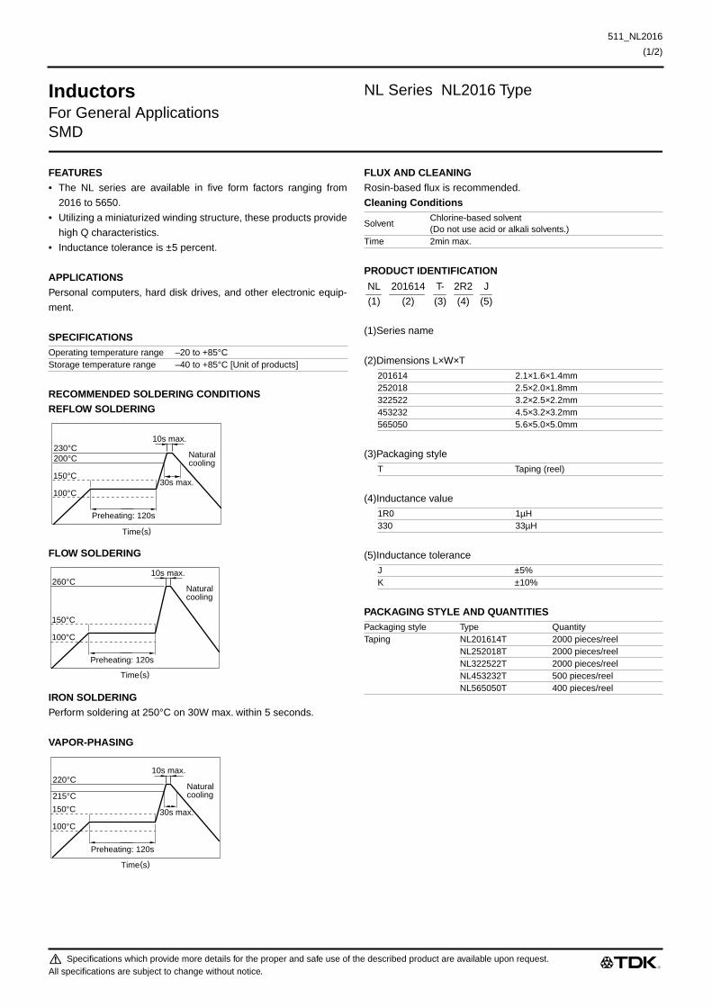
Inductors NL Series NL2016 Type
For General ApplicationsSMD
FEATURES• The NL series are available in five form factors ranging from
2016 to 5650.
• Utilizing a miniaturized winding structure, these products provide
high Q characteristics.
• Inductance tolerance is ±5 percent.
APPLICATIONSPersonal computers, hard disk drives, and other electronic equip-
ment.
SPECIFICATIONS
RECOMMENDED SOLDERING CONDITIONSREFLOW SOLDERING
FLOW SOLDERING
IRON SOLDERINGPerform soldering at 250°C on 30W max. within 5 seconds.
VAPOR-PHASING
FLUX AND CLEANINGRosin-based flux is recommended.
Cleaning Conditions
PRODUCT IDENTIFICATION
(1)Series name
(2)Dimensions L×W×T
(3)Packaging style
(4)Inductance value
(5)Inductance tolerance
PACKAGING STYLE AND QUANTITIES
Operating temperature range –20 to +85°CStorage temperature range –40 to +85°C [Unit of products]
30s max.
Preheating: 120s
10s max.
100°C
200°C230°C
150°C
Naturalcooling
Time(s)
Preheating: 120s
10s max.
100°C
260°C
150°C
Naturalcooling
Time(s)
Preheating: 120s
10s max.
100°C
215°C
220°C
150°C
Naturalcooling
30s max.
Time(s)
SolventChlorine-based solvent(Do not use acid or alkali solvents.)
Time 2min max.
201614 2.1×1.6×1.4mm252018 2.5×2.0×1.8mm322522 3.2×2.5×2.2mm453232 4.5×3.2×3.2mm565050 5.6×5.0×5.0mm
T Taping (reel)
1R0 1µH330 33µH
J ±5%K ±10%
Packaging style Type QuantityTaping NL201614T 2000 pieces/reel
NL252018T 2000 pieces/reelNL322522T 2000 pieces/reelNL453232T 500 pieces/reelNL565050T 400 pieces/reel
NL 201614 T- 2R2 J
(1) (2) (3) (4) (5)
Specifications which provide more details for the proper and safe use of the described product are available upon request.All specifications are subject to change without notice.

511_NL2016
(2/2)
511_NL2016990818
Inductors NL Series NL2016 Type
For General ApplicationsSMD
SHAPES AND DIMENSIONS/RECOMMENDED PC BOARD PATTERN
ELECTRICAL CHARACTERISTICS
• Inductance tolerance is only standard.• Test equipment L, Q: YHP4194A IMPEDANCE ANALYZER (16085A+16093B+TDK TF-1)
SRF:HP8753C NETWORK ANALYZERRdc:MATSUSHITA VP-2941A DIGITAL MILLIOHM METER
TYPICAL ELECTRICAL CHARACTERISTICSINDUCTANCE vs. FREQUENCY IMPEDANCE vs. FREQUENCY INDUCTANCE vs. DC SUPERPOSITIONCHARACTERISTICS CHARACTERISTICS CHARACTERISTICS
INDUCTANCE CHANGE vs. Q vs. FREQUENCY CHARACTERISTICSTEMPERATURE CHARACTERISTICS
Inductance(µH)
Inductancetolerance
Qmin.
Test frequencyL, Q (MHz)
Self-resonantfrequency (MHz)min.
DC resistance(Ω)max.
Rated current(mA)max.
Part No.
1 ±5% 15 7.96 63 1.2 245 NL201614T-1R0J1.5 ±5% 15 7.96 60 1.45 225 NL201614T-1R5J2.2 ±5% 15 7.96 58 1.8 200 NL201614T-2R2J3.3 ±5% 15 7.96 50 2.3 175 NL201614T-3R3J4.7 ±5% 15 7.96 43 2.8 140 NL201614T-4R7J6.8 ±5% 15 7.96 36 3.4 115 NL201614T-6R8J10 ±5% 10 2.52 30 4.7 98 NL201614T-100J15 ±5% 10 2.52 23 6.5 80 NL201614T-150J22 ±5% 10 2.52 20 8 68 NL201614T-220J33 ±5% 10 2.52 17 10.7 60 NL201614T-330J
2.1±0.2 1.6±0.2
1.4
±0.2
0.5
(0.4)
Terminalelectrode
0.8±0.1 Weight: 15mg
1
Inductor
Solder land pattern
0.810.8 Dimensions in mm
0.1 0.3 1 3 10 30Frequency(MHz)
Indu
ctan
ce( µ
H)
0.1
0.3
1
3
10
30
100
33µH
10µH
1µH
0.1 0.3 1 3 10 30Frequency(MHz)
0.01
0.03
0.1
0.3
1
3
10
30
100
33µH
10µH
1µH
Impe
danc
e( k
Ω)
1 3 10 30 100 1000300DC current(mA)
Indu
ctan
ce( µ
H)
0.1
0.3
1
3
10
30
100
10µH
1µH
33µH
AL=5H C=20000µFTest circuit
DC
Uni
vers
albr
idgeSpecimen
YHP model-4255Aor equivalent
0.1 1 10Frequency(MHz)
0
20
40
60
80
100
Q
10µH
1µH
33µH
Test equipment:YHP 4194A IMPEDANCE ANALYZER
10µH
–40 –200
20 40 60 80Temperature(°C)
∆L/L
( 25°
C)
5
–5
1.5µH
33µH
Specifications which provide more details for the proper and safe use of the described product are available upon request.All specifications are subject to change without notice.

Specifications which provide more details for the proper and safe use of the described product are available upon request.All specifications are subject to change without notice.
511_NL2520
(1/3)
Inductors
NL Series NL2520 Type
For General ApplicationsSMD
FEATURES
• The NL series are available in five form factors ranging from
2016 to 5650.
• Utilizing a miniaturized winding structure, these products provide
high Q characteristics.
• Inductance tolerance is ±5 percent.
APPLICATIONS
Personal computers, hard disk drives, and other electronic equip-
ment.
SPECIFICATIONS
RECOMMENDED SOLDERING CONDITIONSREFLOW SOLDERING
FLOW SOLDERING
IRON SOLDERING
Perform soldering at 250°C on 30W max. within 5 seconds.
VAPOR-PHASING
FLUX AND CLEANING
Rosin-based flux is recommended.
Cleaning Conditions
PRODUCT IDENTIFICATION
(1)Series name
(2)Dimensions L×
W×
T
(3)Packaging style
(4)Inductance value
(5)Inductance tolerance
PACKAGING STYLE AND QUANTITIES
Operating temperature range –20 to +85°CStorage temperature range –40 to +85°C [Unit of products]
30s max.
Preheating: 120s
10s max.
100°C
200°C230°C
150°C
Naturalcooling
Time(s)
Preheating: 120s
10s max.
100°C
260°C
150°C
Naturalcooling
Time(s)
Preheating: 120s
10s max.
100°C
215°C
220°C
150°C
Naturalcooling
30s max.
Time(s)
SolventChlorine-based solvent(Do not use acid or alkali solvents.)
Time 2min max.
201614 2.1×
1.6×
1.4mm252018 2.5×
2.0×
1.8mm322522 3.2×
2.5×
2.2mm453232 4.5×
3.2×
3.2mm565050 5.6×
5.0×
5.0mm
T Taping (reel)
1R0 1µ
H330 33µ
H
J ±5%K ±10%
Packaging style Type QuantityTaping NL201614T 2000 pieces/reel
NL252018T 2000 pieces/reelNL322522T 2000 pieces/reelNL453232T 500 pieces/reelNL565050T 400 pieces/reel
NL 201614 T- 2R2 J
(1) (2) (3) (4) (5)

Specifications which provide more details for the proper and safe use of the described product are available upon request.All specifications are subject to change without notice.
511_NL2520
(2/3)
Inductors
NL Series NL2520 Type
For General ApplicationsSMD
SHAPES AND DIMENSIONS/RECOMMENDED PC BOARD PATTERN
ELECTRICAL CHARACTERISTICS
∗
X: Please specify inductance tolerance, K(±10%) or J(±5%)• Inductance tolerance is only standard.• Test equipment L, Q: YHP4191A IMPEDANCE ANALYZER (16092A) [L 0.1µH]
YHP4194A IMPEDANCE ANALYZER (16085A+16093B+TDK TF-1) [L 0.12µH]SRF:HP8753C NETWORK ANALYZERRdc:MATSUSHITA VP-2941A DIGITAL MILLIOHM METER
Inductance(µH)
Inductancetolerance
Qmin.
Test frequencyL, Q (MHz)
Self-resonantfrequency (MHz)min.
DC resistance(Ω
)max.Rated current(mA)max.
Part No.
0.01 ±10, ±5% 15 100 2150 0.26 530 NL252018T-010X∗
0.012 ±10, ±5% 15 100 2050 0.27 500 NL252018T-012X0.015 ±10, ±5% 15 100 2000 0.29 480 NL252018T-015X0.018 ±10, ±5% 15 100 1850 0.31 450 NL252018T-018X0.022 ±10, ±5% 15 100 1650 0.37 420 NL252018T-022X0.027 ±10, ±5% 15 100 1550 0.4 410 NL252018T-027X0.033 ±10, ±5% 20 100 1450 0.42 400 NL252018T-033X0.039 ±10, ±5% 20 100 1350 0.45 380 NL252018T-039X0.047 ±10, ±5% 20 100 1200 0.5 360 NL252018T-047X0.056 ±10, ±5% 20 100 1100 0.6 340 NL252018T-056X0.068 ±10, ±5% 20 100 1050 0.65 320 NL252018T-068X0.082 ±10, ±5% 20 100 900 0.75 300 NL252018T-082X0.1 ±10, ±5% 20 100 800 0.8 280 NL252018T-R10X0.12 ±10, ±5% 30 25.2 700 0.3 550 NL252018T-R12X0.15 ±10, ±5% 30 25.2 550 0.35 500 NL252018T-R15X0.18 ±10, ±5% 30 25.2 500 0.4 460 NL252018T-R18X0.22 ±10, ±5% 30 25.2 450 0.5 430 NL252018T-R22X0.27 ±10, ±5% 30 25.2 425 0.55 420 NL252018T-R27X0.33 ±10, ±5% 30 25.2 400 0.6 400 NL252018T-R33X0.39 ±10, ±5% 30 25.2 375 0.65 375 NL252018T-R39X0.47 ±10, ±5% 30 25.2 350 0.68 350 NL252018T-R47X0.56 ±10, ±5% 30 25.2 325 0.75 325 NL252018T-R56X0.68 ±10, ±5% 30 25.2 300 0.85 300 NL252018T-R68X0.82 ±10, ±5% 30 25.2 260 1 260 NL252018T-R82X1 ±5% 30 7.96 245 1.1 245 NL252018T-1R0J1.2 ±5% 30 7.96 230 1.2 230 NL252018T-1R2J1.5 ±5% 30 7.96 182 1.3 220 NL252018T-1R5J1.8 ±5% 30 7.96 135 1.45 210 NL252018T-1R8J2.2 ±5% 30 7.96 105 1.55 200 NL252018T-2R2J2.7 ±5% 30 7.96 70 1.7 195 NL252018T-2R7J3.3 ±5% 30 7.96 55 1.9 185 NL252018T-3R3J3.9 ±5% 30 7.96 48 2.1 180 NL252018T-3R9J4.7 ±5% 30 7.96 43 2.3 175 NL252018T-4R7J5.6 ±5% 25 7.96 42 2.5 170 NL252018T-5R6J6.8 ±5% 25 7.96 39 2.7 165 NL252018T-6R8J8.2 ±5% 25 7.96 36 3.05 160 NL252018T-8R2J10 ±5% 25 2.52 33 3.5 155 NL252018T-100J12 ±5% 25 2.52 30 3.8 150 NL252018T-120J15 ±5% 25 2.52 26 4.4 140 NL252018T-150J
2.5±0.2 2±0.2
1.8
±0.2
0.5
(0.4)
Terminalelectrode
1.4±0.1 Weight: 25mg
1.5
Inductor
Solder land pattern
1.01.51.0 Dimensions in mm
10

511_NL2520
000120
Specifications which provide more details for the proper and safe use of the described product are available upon request.All specifications are subject to change without notice.
511_NL2520
(3/3)
Inductors
NL Series NL2520 Type
For General ApplicationsSMD
ELECTRICAL CHARACTERISTICS
• Inductance tolerance is only standard.• Test equipment Inductance, Q: YHP4194A IMPEDANCE ANALYZER (16085A+16093B+TDK TF-1)
SRF: HP8753C NETWORK ANALYZER Rdc: MATSUSHITA VP-2941A DIGITAL MILLIOHM METER
TYPICAL ELECTRICAL CHARACTERISTICSINDUCTANCE vs. FREQUENCY CHARACTERISTICS
INDUCTANCE CHANGE vs. DC SUPERPOSITIONCHARACTERISTICS
IMPEDANCE vs. FREQUENCY CHARACTERISTICS
INDUCTANCE CHANGE vs. TEMPERATURECHARACTERISTICS
Q vs. FREQUENCY CHARACTERISTICS
Inductance(µH)
Inductancetolerance
Qmin.
Test frequencyL, Q (MHz)
Self-resonantfrequency (MHz)min.
DC resistance(Ω
)max.Rated current(mA)max.
Part No.
18 ±5% 25 2.52 24 4.8 130 NL252018T-180J22 ±5% 25 2.52 22 5.5 125 NL252018T-220J27 ±5% 25 2.52 21 6.3 115 NL252018T-270J33 ±5% 25 2.52 20 7.1 110 NL252018T-330J39 ±5% 20 2.52 18 9.5 90 NL252018T-390J47 ±5% 20 2.52 17 11.1 80 NL252018T-470J56 ±5% 20 2.52 16 12.1 75 NL252018T-560J68 ±5% 20 2.52 15 16.6 70 NL252018T-680J82 ±5% 20 2.52 13 19 66 NL252018T-820J100 ±5% 15 0.796 12 21 60 NL252018T-101J
0.10.2
1
10
100
1000
1 10 40Frequency(MHz)
Indu
ctan
ce( µ
H)
100µH
56µH
22µH
10µH
1µH
4.7µH
4194A IMPEDANCE/GAIN-PHASEANALYZER
51
5
10
50
100
500
1000
10 50 100 500 1000
Indu
ctan
ce( µ
H)
DC current(mA)
100µH
56µH
22µH
10µH
2.2µH
4.7µH
AL=5H C=20000µFTest circuit
DC
Uni
vers
albr
idgeSpecimen
YHP model-4255Aor equivalent
Frequency(MHz)0.1
0.02
0.1
0.05
1
10
5
0.5
100
50
10.5 105 40
Impe
danc
e( k
Ω)
100µH
10µH
1µH
4194A IMPEDANCE/GAIN-PHASEANALYZER
Test equipment: YHP 4194A IMPEDANCE ANALYZER at 0.1MHz
4.7µH–40 –20
0
20 40 60 80Temperature(°C)
∆L/L
20°C
( %)
5
–5
0.15µH
100µH4.7µH
0.15µH100µH
0.1 1 10Frequency(MHz)
0
20
40
60
80
100
Q
56µH
10µH
4.7µH1µH
22µH100µH
Test equipment:YHP 4194A IMPEDANCE ANALYZER
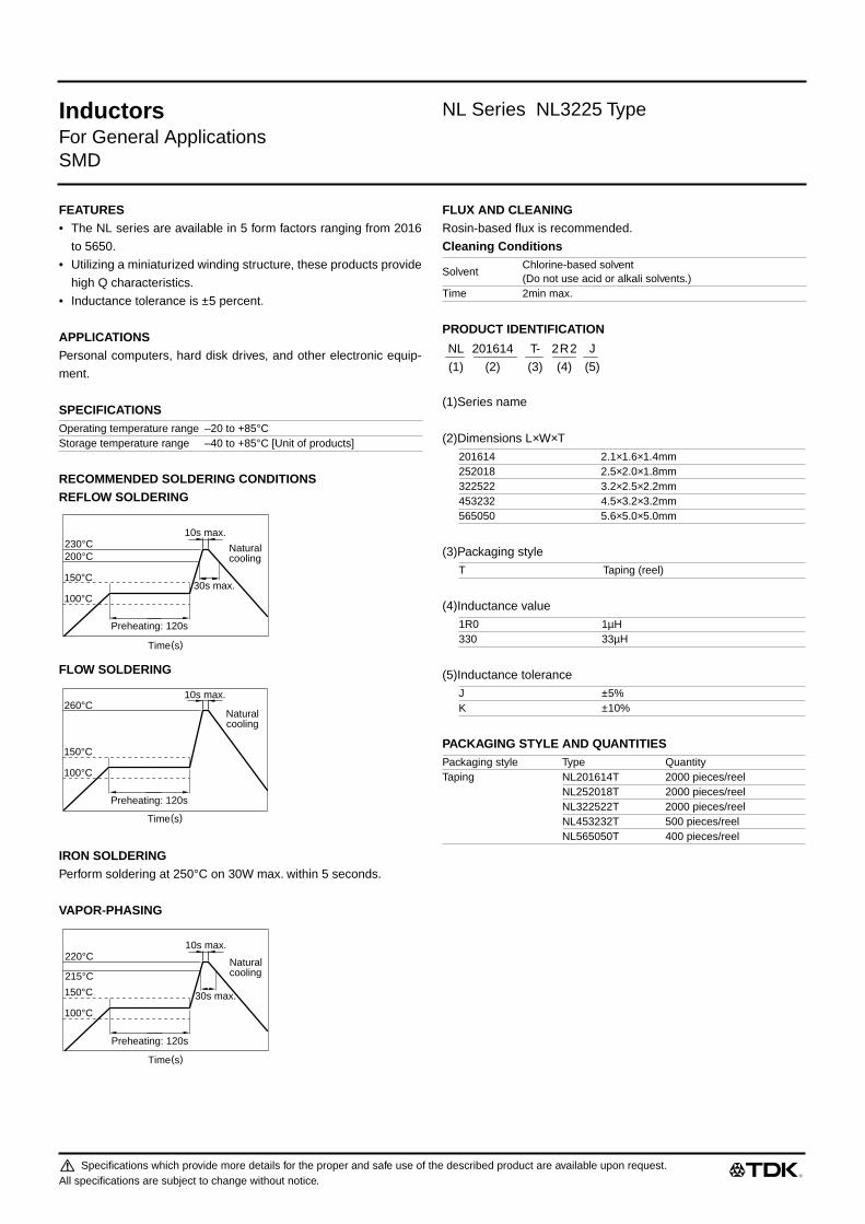
Inductors NL Series NL3225 Type
For General ApplicationsSMD
FEATURES• The NL series are available in 5 form factors ranging from 2016
to 5650.
• Utilizing a miniaturized winding structure, these products provide
high Q characteristics.
• Inductance tolerance is ±5 percent.
APPLICATIONSPersonal computers, hard disk drives, and other electronic equip-
ment.
SPECIFICATIONS
RECOMMENDED SOLDERING CONDITIONSREFLOW SOLDERING
FLOW SOLDERING
IRON SOLDERINGPerform soldering at 250°C on 30W max. within 5 seconds.
VAPOR-PHASING
FLUX AND CLEANINGRosin-based flux is recommended.
Cleaning Conditions
PRODUCT IDENTIFICATION
(1)Series name
(2)Dimensions L×W×T
(3)Packaging style
(4)Inductance value
(5)Inductance tolerance
PACKAGING STYLE AND QUANTITIES
Operating temperature range –20 to +85°CStorage temperature range –40 to +85°C [Unit of products]
30s max.
Preheating: 120s
10s max.
100°C
200°C230°C
150°C
Naturalcooling
Time(s)
Preheating: 120s
10s max.
100°C
260°C
150°C
Naturalcooling
Time(s)
Preheating: 120s
10s max.
100°C
215°C
220°C
150°C
Naturalcooling
30s max.
Time(s)
SolventChlorine-based solvent(Do not use acid or alkali solvents.)
Time 2min max.
201614 2.1×1.6×1.4mm252018 2.5×2.0×1.8mm322522 3.2×2.5×2.2mm453232 4.5×3.2×3.2mm565050 5.6×5.0×5.0mm
T Taping (reel)
1R0 1µH330 33µH
J ±5%K ±10%
Packaging style Type QuantityTaping NL201614T 2000 pieces/reel
NL252018T 2000 pieces/reelNL322522T 2000 pieces/reelNL453232T 500 pieces/reelNL565050T 400 pieces/reel
NL 201614 T- 2R2 J
(1) (2) (3) (4) (5)
Specifications which provide more details for the proper and safe use of the described product are available upon request.All specifications are subject to change without notice.

Inductors NL Series NL3225 Type
For General ApplicationsSMD
SHAPES AND DIMENSIONS/RECOMMENDED PC BOARD PATTERN
ELECTRICAL CHARACTERISTICS
∗ X: Please specify the inductance tolerance, K(±10%) or J(±5%)• Inductance tolerance is only standard.• Test equipment L, Q: YHP4194A IMPEDANCE ANALYZER (16085A+16093B+TDK TF-1) [L 0.12µH]
SRF: HP8753C NETWORK ANALYZERRdc: MATSUSHITA VP-2941A DIGITAL MILLIOHM METER
Inductance(µH)
Inductancetolerance
Q min.
Test frequencyL, Q (MHz)
Self-resonantfrequency (MHz)min.
DC resistance(Ω)max.
Rated current(mA)max.
Part No.
0.01 ±10, ±5% 15 100 2500 0.13 450 NL322522T-010X∗
0.012 ±10, ±5% 17 100 2300 0.14 450 NL322522T-012X0.015 ±10, ±5% 19 100 2100 0.16 450 NL322522T-015X0.018 ±10, ±5% 21 100 1900 0.18 450 NL322522T-018X0.022 ±10, ±5% 23 100 1700 0.2 450 NL322522T-022X0.027 ±10, ±5% 23 100 1500 0.22 450 NL322522T-027X0.033 ±10, ±5% 25 100 1400 0.24 450 NL322522T-033X0.039 ±10, ±5% 25 100 1300 0.27 450 NL322522T-039X0.047 ±10, ±5% 26 100 1200 0.3 450 NL322522T-047X0.056 ±10, ±5% 26 100 1100 0.33 450 NL322522T-056X0.068 ±10, ±5% 27 100 1000 0.36 450 NL322522T-068X0.082 ±10, ±5% 27 100 900 0.4 450 NL322522T-082X0.1 ±10, ±5% 28 100 700 0.44 450 NL322522T-R10X0.12 ±10, ±5% 30 25.2 500 0.22 450 NL322522T-R12X0.15 ±10, ±5% 30 25.2 450 0.25 450 NL322522T-R15X0.18 ±10, ±5% 30 25.2 400 0.28 450 NL322522T-R18X0.22 ±10, ±5% 30 25.2 350 0.32 450 NL322522T-R22X0.27 ±10, ±5% 30 25.2 320 0.36 450 NL322522T-R27X0.33 ±10, ±5% 30 25.2 300 0.4 450 NL322522T-R33X0.39 ±10, ±5% 30 25.2 250 0.45 450 NL322522T-R39X0.47 ±10, ±5% 30 25.2 220 0.5 450 NL322522T-R47X0.56 ±10, ±5% 30 25.2 180 0.55 450 NL322522T-R56X0.68 ±10, ±5% 30 25.2 160 0.6 450 NL322522T-R68X0.82 ±10, ±5% 30 25.2 140 0.65 450 NL322522T-R82X1 ±5% 30 7.96 120 0.7 400 NL322522T-1R0J1.2 ±5% 30 7.96 100 0.75 390 NL322522T-1R2J1.5 ±5% 30 7.96 85 0.85 370 NL322522T-1R5J1.8 ±5% 30 7.96 80 0.9 350 NL322522T-1R8J2.2 ±5% 30 7.96 75 1 320 NL322522T-2R2J2.7 ±5% 30 7.96 70 1.1 290 NL322522T-2R7J3.3 ±5% 30 7.96 60 1.2 260 NL322522T-3R3J3.9 ±5% 30 7.96 55 1.3 250 NL322522T-3R9J4.7 ±5% 30 7.96 50 1.5 220 NL322522T-4R7J5.6 ±5% 30 7.96 45 1.6 200 NL322522T-5R6J6.8 ±5% 30 7.96 40 1.8 180 NL322522T-6R8J8.2 ±5% 30 7.96 35 2 170 NL322522T-8R2J10 ±5% 30 2.52 30 2.1 150 NL322522T-100J12 ±5% 30 2.52 20 2.5 140 NL322522T-120J
470J
3.2±0.2 2.5±0.2
2.2
±0.2
0.5
(0.4)
Terminalelectrode
1.9±0.1 Weight: 50mg
2
Inductor
Pattern
121 Dimensions in mm
Specifications which provide more details for the proper and safe use of the described product are available upon request.All specifications are subject to change without notice.

Inductors NL Series NL3225 Type
For General ApplicationsSMD
ELECTRICAL CHARACTERISTICS
• Inductance tolerance is only standard.• Test equipment L, Q: YHP4194A IMPEDANCE ANALYZER (16085A+16093B+TDK TF-1) [L 0.12µH]
SRF: HP8753C NETWORK ANALYZERRdc: MATSUSHITA VP-2941A DIGITAL MILLIOHM METER
TYPICAL ELECTRICAL CHARACTERISTICSINDUCTANCE vs. FREQUENCY CHARACTERISTICS INDUCTANCE CHANGE vs. DC
SUPERPOSITION CHARACTERISTICS
Inductance(µH)
Inductancetolerance
Q min.
Test frequencyL, Q (MHz)
Self-resonantfrequency(MHz)min.
DC resistance(Ω)max.
Rated current(mA)max.
Part No.
15 ±5% 30 2.52 20 2.8 130 NL322522T-150J18 ±5% 30 2.52 20 3.3 120 NL322522T-180J22 ±5% 30 2.52 20 3.7 110 NL322522T-220J27 ±5% 30 2.52 20 5 80 NL322522T-270J33 ±5% 30 2.52 17 5.6 70 NL322522T-330J39 ±5% 30 2.52 16 6.4 65 NL322522T-390J47 ±5% 30 2.52 15 7 60 NL322522T-470J56 ±5% 30 2.52 13 8 55 NL322522T-560J68 ±5% 30 2.52 12 9 50 NL322522T-680J82 ±5% 30 2.52 11 10 45 NL322522T-820J100 ±5% 20 0.796 10 10 40 NL322522T-101J120 ±5% 20 0.796 10 11 70 NL322522T-121J150 ±5% 20 0.796 8 15 65 NL322522T-151J180 ±5% 20 0.796 7 17 60 NL322522T-181J220 ±5% 20 0.796 7 21 50 NL322522T-221J270 ±5% 20 0.796 6 28 45 NL322522T-271J330 ±5% 20 0.796 5 34 40 NL322522T-331J390 ±5% 20 0.796 5 42 35 NL322522T-391J470 ±5% 20 0.796 4 40 25 NL322522T-471J
0.10.2
1
0.5
10
5
100
50
1000
500
1 50.5 10 40Frequency(MHz)
Indu
ctan
ce( µ
H)
100µH
220µH
10µH
1µH
4194A IMPEDANCE/GAIN-PHASEANALYZER
0.5 1 105 100 100050 500Frequency(MHz)
0.01µH
0.015µH
0.05
0.01
0.05
0.1
1
0.5
Indu
ctan
ce( µ
H)
0.1µH
0.068µH
0.047µH
0.033µH
0.022µH
Test equipment:RF IMPEDANCE ANALYZER 4191A, YHP
50.5
1
5
10
50
100
500
1000
10 50 100 500 1000
Indu
ctan
ce( µ
H)
DC current(mA)
220µH
82µH
47µH
18µH
12µH
8.2µH
1.5µH
100µH
AL=5H C=20000µFTest circuit
DC
Uni
vers
albr
idgeSpecimen
YHP model-4255Aor equivalent
Specifications which provide more details for the proper and safe use of the described product are available upon request.All specifications are subject to change without notice.

511_NL3225
Inductors NL Series NL3225 Type
For General ApplicationsSMD
TYPICAL ELECTRICAL CHARACTERISTICSIMPEDANCE vs. FREQUENCY CHARACTERISTICS INDUCTANCE CHANGE vs. TEMPERATURE
CHARACTERISTICS
Q vs. FREQUENCY CHARACTERISTICS
0.5
5
10
50
100
500
1000
1 105 100 100050 500
Impe
danc
e( Ω
)
Frequency(MHz)
0.1µH
0.047µH
0.022µH0.01µH
Test equipment:RF IMPEDANCE ANALYZER 4191A, YHP
100µH
220µH
10µH
1µH
Frequency(MHz)0.1
100
50
1k
10k
5k
500
100k
50k
10.5 105 40
Impe
danc
e( Ω
)
4194A IMPEDANCE/GAIN-PHASEANALYZER
8.2µH33µH
100µH100µH3.3µH
8.2µH
–40 –20 020 40 60 80
Temperature(°C)
∆L
/L2
0°C( %
)
Test equipment: LCR model-4275A, YHP at 10kHz 1Vrms
5
–5
0.022µH
0.047µH0.1µH
0.01µH
0.5
5
10
50
100
500
1000
1 105 100 100050 500
Q
Frequency(MHz)
Test equipment:RF IMPEDANCE ANALYZER 4191A, YHP
0.10.05 10.5 105Frequency(MHz)
0
20
40
60
80
100
Q
2.2µH
4.7µH10µH
68µH100µH
220µH
Test equipment:Q meter model-4343B, YHP
33µH
980330
Specifications which provide more details for the proper and safe use of the described product are available upon request.All specifications are subject to change without notice.

Inductors NL Series NL4532 Type
For General ApplicationsSMD
FEATURES• The NL series are available in 5 form factors ranging from 2016
to 5650.
• Utilizing a miniaturized winding structure, these products provide
high Q characteristics.
• Inductance tolerance is ±5 percent.
APPLICATIONSPersonal computers, hard disk drives, and other electronic equip-
ment.
SPECIFICATIONS
RECOMMENDED SOLDERING CONDITIONSREFLOW SOLDERING
FLOW SOLDERING
IRON SOLDERINGPerform soldering at 250°C on 30W max. within 5 seconds.
VAPOR-PHASING
FLUX AND CLEANINGRosin-based flux is recommended.
Cleaning Conditions
PRODUCT IDENTIFICATION
(1)Series name
(2)Dimensions L×W×T
(3)Packaging style
(4)Inductance value
(5)Inductance tolerance
PACKAGING STYLE AND QUANTITIES
Operating temperature range –20 to +85°CStorage temperature range –40 to +85°C [Unit of products]
30s max.
Preheating: 120s
10s max.
100°C
200°C230°C
150°C
Naturalcooling
Time(s)
Preheating: 120s
10s max.
100°C
260°C
150°C
Naturalcooling
Time(s)
Preheating: 120s
10s max.
100°C
215°C
220°C
150°C
Naturalcooling
30s max.
Time(s)
SolventChlorine-based solvent(Do not use acid or alkali solvents.)
Time 2min max.
201614 2.1×1.6×1.4mm252018 2.5×2.0×1.8mm322522 3.2×2.5×2.2mm453232 4.5×3.2×3.2mm565050 5.6×5.0×5.0mm
T Taping (reel)
1R0 1µH330 33µH
J ±5%K ±10%
Packaging style Type QuantityTaping NL201614T 2000 pieces/reel
NL252018T 2000 pieces/reelNL322522T 2000 pieces/reelNL453232T 500 pieces/reelNL565050T 400 pieces/reel
NL 201614 T- 2R2 J
(1) (2) (3) (4) (5)
Specifications which provide more details for the proper and safe use of the described product are available upon request.All specifications are subject to change without notice.
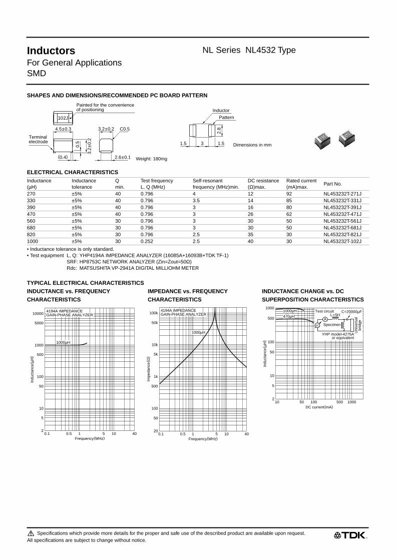
Inductors NL Series NL4532 Type
For General ApplicationsSMD
SHAPES AND DIMENSIONS/RECOMMENDED PC BOARD PATTERN
ELECTRICAL CHARACTERISTICS
• Inductance tolerance is only standard.• Test equipment L, Q: YHP4194A IMPEDANCE ANALYZER (16085A+16093B+TDK TF-1)
SRF: HP8753C NETWORK ANALYZER (Zin=Zout=50Ω)Rdc: MATSUSHITA VP-2941A DIGITAL MILLIOHM METER
TYPICAL ELECTRICAL CHARACTERISTICSINDUCTANCE vs. FREQUENCY IMPEDANCE vs. FREQUENCY INDUCTANCE CHANGE vs. DCCHARACTERISTICS CHARACTERISTICS SUPERPOSITION CHARACTERISTICS
Inductance(µH)
Inductancetolerance
Qmin.
Test frequencyL, Q (MHz)
Self-resonantfrequency (MHz)min.
DC resistance(Ω)max.
Rated current(mA)max.
Part No.
270 ±5% 40 0.796 4 12 92 NL453232T-271J330 ±5% 40 0.796 3.5 14 85 NL453232T-331J390 ±5% 40 0.796 3 16 80 NL453232T-391J470 ±5% 40 0.796 3 26 62 NL453232T-471J560 ±5% 30 0.796 3 30 50 NL453232T-561J680 ±5% 30 0.796 3 30 50 NL453232T-681J820 ±5% 30 0.796 2.5 35 30 NL453232T-821J1000 ±5% 30 0.252 2.5 40 30 NL453232T-102J
C0.5
Painted for the convenienceof positioning
102J
4.5±0.3 3.2±0.2
3.2
±0.2
0.5
(0.4)
Terminalelectrode
2.6±0.1 Weight: 180mg
2.8
Inductor
Pattern
1.531.5 Dimensions in mm
10
5
2
10
50
100
500
1000
50 100 500 1000
Indu
ctan
ce( µ
H)
DC current(mA)
470µH1000µH
AL=5H
C=20000µFTest circuit
DC
Uni
vers
albr
idgeSpecimen
YHP model-4275Aor equivalent
Frequency(MHz)0.1
10
5
2
100
1000
500
50
10000
5000
10.5 105 40
Indu
ctan
ce( µ
H)
1000µH
4194A IMPEDANCEGAIN-PHASE ANALYZER
Frequency(MHz)0.1
100
50
20
1k
10k
5k
500
100k
50k
10.5 105 40
Impe
danc
e( Ω
)
1000µH
4194A IMPEDANCEGAIN-PHASE ANALYZER
Specifications which provide more details for the proper and safe use of the described product are available upon request.All specifications are subject to change without notice.

511_NL4532
Inductors NL Series NL4532 Type
For General ApplicationsSMD
TYPICAL ELECTRICAL CHARACTERISTICSINDUCTANCE CHANGE vs. TEMPERATURE Q vs. FREQUENCY CHARACTERISTICSCHARACTERISTICS
4
330µH
–2
–3
–4
–1
1
2
3
–20 020 40 60 80 100
∆L
/L20
°C( %
)
Temperature(°C)
Test equipment: LCR model-4275A YHP, at 10kHz 1Vrms
0.10.05 10.5 105Frequency(MHz)
0
20
40
60
80
100
Q
470µH
1000µH
Test equipment: Q meter model-4340A, YHP
980330
Specifications which provide more details for the proper and safe use of the described product are available upon request.All specifications are subject to change without notice.

Inductors NL Series NL5650 Type
For General ApplicationsSMD
FEATURES• The NL series are available in 5 form factors ranging from 2016
to 5650.
• Utilizing a miniaturized winding structure, these products provide
high Q characteristics.
• Inductance tolerance is ±5 percent.
APPLICATIONSPersonal computers, hard disk drives, and other electronic equip-
ment.
SPECIFICATIONS
RECOMMENDED SOLDERING CONDITIONSREFLOW SOLDERING
FLOW SOLDERING
IRON SOLDERINGPerform soldering at 250°C on 30W max. within 5 seconds.
VAPOR-PHASING
FLUX AND CLEANINGRosin-based flux is recommended.
Cleaning Conditions
PRODUCT IDENTIFICATION
(1)Series name
(2)Dimensions L×W×T
(3)Packaging style
(4)Inductance value
(5)Inductance tolerance
PACKAGING STYLE AND QUANTITIES
Operating temperature range –20 to +85°CStorage temperature range –40 to +85°C [Unit of products]
30s max.
Preheating: 120s
10s max.
100°C
200°C230°C
150°C
Naturalcooling
Time(s)
Preheating: 120s
10s max.
100°C
260°C
150°C
Naturalcooling
Time(s)
Preheating: 120s
10s max.
100°C
215°C
220°C
150°C
Naturalcooling
30s max.
Time(s)
SolventChlorine-based solvent(Do not use acid or alkali solvents.)
Time 2min max.
201614 2.1×1.6×1.4mm252018 2.5×2.0×1.8mm322522 3.2×2.5×2.2mm453232 4.5×3.2×3.2mm565050 5.6×5.0×5.0mm
T Taping (reel)
1R0 1µH330 33µH
J ±5%K ±10%
Packaging style Type QuantityTaping NL201614T 2000 pieces/reel
NL252018T 2000 pieces/reelNL322522T 2000 pieces/reelNL453232T 500 pieces/reelNL565050T 400 pieces/reel
NL 201614 T- 2R2 J
(1) (2) (3) (4) (5)
Specifications which provide more details for the proper and safe use of the described product are available upon request.All specifications are subject to change without notice.

511_NL5650
Inductors NL Series NL5650 Type
For General ApplicationsSMD
SHAPES AND DIMENSIONS/RECOMMENDED PC BOARD PATTERN
ELECTRICAL CHARACTERISTICS
• Inductance tolerance is only standard.• Test equipment L, Q: YHP4194A IMPEDANCE ANALYZER (16085A+16093B+TDK TF-1)
SRF: HP8753C NETWORK ANALYZER (Zin=Zout=50Ω)Rdc: MATSUSHITA VP-2941A DIGITAL MILLIOHM METER
TYPICAL ELECTRICAL CHARACTERISTICSINDUCTANCE CHANGE vs. DC INDUCTANCE CHANGE vs. Q vs. FREQUENCYSUPERPOSITION CHARACTERISTICS TEMPERATURE CHARACTERISTICS CHARACTERISTICS
Inductance(mH)
Inductancetolerance
Qmin.
Test frequencyL, Q (MHz)
Self-resonantfrequency (MHz)min.
DC resistance(Ω)max.
Rated current(mA)max.
Part No.
1.2 ±5% 30 0.252 1.5 17 75 NL565050T-122J1.5 ±5% 30 0.252 1.4 20 70 NL565050T-152J1.8 ±5% 30 0.252 1.3 30 60 NL565050T-182J2.2 ±5% 30 0.252 1.2 35 55 NL565050T-222J2.7 ±5% 30 0.252 1.1 55 45 NL565050T-272J3.3 ±5% 30 0.252 1 60 40 NL565050T-332J3.9 ±5% 30 0.252 1 70 38 NL565050T-392J4.7 ±5% 30 0.252 0.9 78 36 NL565050T-472J5.6 ±5% 30 0.252 0.8 85 33 NL565050T-562J6.8 ±5% 30 0.252 0.7 110 30 NL565050T-682J8.2 ±5% 30 0.252 0.6 125 28 NL565050T-822J10 ±5% 20 0.0796 0.5 150 25 NL565050T-103J
472J
5.6±0.3 C15±0.3
5±0
.3
1
(0.5)
Terminalelectrode
4±0.2 Weight: 380mg
4.5
Inductor
Pattern
242 Dimensions in mm
DC current(mA)
Indu
ctan
ce( m
H)
50100.5
1
5
10
50
100
100 500
10mH
5.6mH
2.7mH
1.2mH
AL=5H C=20000µFTest circuit
DC
Uni
vers
albr
idgeSpecimen
YHP model-4275Aor equivalent
Temperature(˚C)
YHP 4194A IMPEDANCE ANALYZERat 10kHz 0.5V
4
2
0
–4
–2
–40 –20 0 20 40 60 80 100
∆L
/L20
˚C( %
)
2.2mH
0.1 0.5 1 5 10
10mH5.6mH
3.3mH1.8mH
0
20
40
60
80
100
Q
Test equipment:Q meter model-4343B, YHP
Frequency(MHz)
980330
Specifications which provide more details for the proper and safe use of the described product are available upon request.All specifications are subject to change without notice.

Specifications which provide more details for the proper and safe use of the described product are available upon request.All specifications are subject to change without notice.
511_NLV25
(1/3)
Inductors
NLV Series NLV25 Type
For General ApplicationsSMD
FEATURES
• Provides high Q while using 252018 size winding construction.
• Environmentally friendly due to use of recyclable plastic (ther-
moplastic).
• Logo omitted to simplify production.
• Maintains interchangeability with earlier NL product series.
• NLV series are E-6 products, while NLCV and NLFV series are
E-3 products.
APPLICATIONS
PCs, hard disk drives, and other types of electronics
SPECIFICATIONS
RECOMMENDED SOLDERING CONDITIONSREFLOW SOLDERING
FLOW SOLDERING
IRON SOLDERING
Perform soldering at 250°C on 30W max. within 5 seconds.
VAPOR-PHASING
PRODUCT IDENTIFICATION
(1) Series name
(2) Dimensions LxWxT
(3) Packaging style
(4) Inductance value
(5) Inductance tolerance
PACKAGING STYLE AND QUANTITIES
PRECAUTIONS
• The exterior of this product can melt since due to thermoplastic
construction. During mechanical contact while at the plastic soft-
ening temperature, deformation can occur at the contact loca-
tion. Therefore caution is required when utilizing a soldering iron
during the soldering operation.
FLUX AND CLEANING
Rosin-based flux is recommended.
Cleaning Conditions
TypeOperating temperature range
Storage temperature range[Unit of products]
NLV25 –20 to +85°C –40 to +85°CNLCV25 –20 to +85°C –40 to +85°CNLFV25 –20 to +85°C –40 to +85°C
30s max.
10s max.
100°C
200°C230°C
150°C
Preheating:120s
Naturalcooling
Time(s)
10s max.
100°C
260°C
150°C
Preheating:120s
Naturalcooling
Time(s)
10s max.
100°C
215°C
220°C
150°C 30s max.
Preheating:120s
Naturalcooling
Time(s)
252018 2.5×
2.0×
1.8mm
T Taping (reel)
1R0 1µ
H220 22µ
H
J ±5%K ±10%M ±20%
Packaging style Type QuantityTaping NLV25T 2000 pieces/reel
NLCV25T 2000 pieces/reelNLFV25T 2000 pieces/reel
SolventChlorine-based solvent(Do not use acid or alkali solvents.)
Time 2min max.
NLV 25 T- 2R2 J
(1) (2) (3) (4) (5)

Specifications which provide more details for the proper and safe use of the described product are available upon request.All specifications are subject to change without notice.
511_NLV25
(2/3)
Inductors
NLV Series NLV25 Type
For General ApplicationsSMD
SHAPES AND DIMENSIONS/RECOMMENDED PC BOARD PATTERN
ELECTRICAL CHARACTERISTICS
• Test equipment L, Q: HP4191A IMPEDANCE/GAIN PHASE ANALYZER(16085A+16093B+TDK TF-1)SRF: HP8753C NETWORK ANALYZERRdc: MATSUSHITA VP-2941A DIGITAL MILLIOHM METER
Inductance(µH)Inductance tolerance
Qtyp.
Test frequency L,Q(MHz)
Self-resonant frequency(MHz)min.
DC resistance(Ω
)max.Rated current(mA)max.
Part No.
1 ±5% 30 7.96 245 1.1 245 NLV25T-1R0J1.5 ±5% 30 7.96 182 1.3 220 NLV25T-1R5J2.2 ±5% 30 7.96 105 1.55 200 NLV25T-2R2J3.3 ±5% 30 7.96 55 1.9 185 NLV25T-3R3J4.7 ±5% 30 7.96 43 2.3 175 NLV25T-4R7J6.8 ±5% 25 7.96 39 2.7 165 NLV25T-6R8J10 ±5% 25 2.52 33 3.5 155 NLV25T-100J15 ±5% 25 2.52 26 4.4 140 NLV25T-150J22 ±5% 25 2.52 22 5.5 125 NLV25T-220J33 ±5% 20 2.52 20 7.1 110 NLV25T-330J47 ±5% 20 2.52 17 11.1 80 NLV25T-470J68 ±5% 20 2.52 15 16.6 70 NLV25T-680J100 ±5% 15 0.796 12 21 60 NLV25T-101J
2.5±0.2 2±0.1
1.8±
0.1
0.5
(0.4) 1.4±0.1
1.5
1.01.51.0
Terminalelectrode
Weight:25mg
Inductor
Solder land pattern
Dimensions in mm

511_NLV25
000120
Specifications which provide more details for the proper and safe use of the described product are available upon request.All specifications are subject to change without notice.
511_NLV25
(3/3)
Inductors
NLV Series NLV25 Type
For General ApplicationsSMD
TYPICAL ELECTRICAL CHARACTERISTICSINDUCTANCE CHANGE vs. FREQUENCY CHARACTERISTICS IMPEDANCE vs. FREQUENCY CHARACTERISTICS
INDUCTANCE CHANGE vs. DC SUPERPOSITION INDUCTANCE CHANGE vs. TEMPERATURE CHARACTERISTICS CHARACTERISTICS
Q vs. FREQUENCY CHARACTERISTICS
0.10.2
1
10
100
1000
1 10 40
100µH
22µH
10µH
1µH
4.7µH
4194A IMPEDANCE/GAIN-PHASEANALYZER
Frequency(MHz)
Indu
ctan
ce( µ
H)
0.10.02
0.1
0.05
1
10
5
0.5
100
50
10.5 105 40
100µH
10µH
1µH
4194A IMPEDANCE/GAIN-PHASEANALYZER
Frequency(MHz)
Impe
danc
e(kΩ
)
51
5
10
50
100
500
1000
10 50 100 500 1000
100µH
22µH
10µH
2.2µH
4.7µH
AL=5H C=20000µFTest circuit
DC
Uni
vers
albr
idgeSpecimen
HP model-4255Aor equivalent
DC current(mA)
Indu
ctan
ce( µ
H)
Test equipment: HP 4194A IMPEDANCE ANALYZER at 0.1MHz
4.7µH–40 –20
0
20 40 60 80Temperature(°C)
∆L
/L20
°C( %
)
5
–5
100µH100µH
4.7µH
0.1 1 10Frequency(MHz)
0
20
40
60
80
100
Q 10µH
4.7µH1µH
22µH100µH
Test equipment:HP 4194A IMPEDANCE ANALYZER

Specifications which provide more details for the proper and safe use of the described product are available upon request.All specifications are subject to change without notice.
512_EL0305
(1/3)
Inductors
EL Series EL0305 Type
For General ApplicationsRadial
FEATURES
• The EL series inductors are available in 6 form factors ranging
from 0304 to 0909.
• With a miniature winding construction, these inductors nonethe-
less achieve high Q characteristics.
• Available in tape packaging to support automated mounting
machines.
APPLICATIONS
Televisions, VCRs, personal computers, and other electronic
equipment.
SPECIFICATIONS
PRODUCT IDENTIFICATION
(1)Series name
(2)Dimensions
(3)Packaging style
(4)Inductance value
(5)Inductance tolerance
(6)TDK internal code
(Some products may not have this number. See the main body
for details.)
PACKAGING STYLE AND QUANTITIES
Operating temperature range –20 to +80°C [Including self-temperature rise]
Storage temperature range –40 to +80°C [Unit of products]Terminal tensile strength EL0304: 4.9N min.
EL0305: 7.84N min.EL0405: 7.84N min.EL0606: 14.7N min.EL0607: 14.7N min.EL0909: 14.7N min.
0304 4
×
3
×
4mm (lead pitch 2.5mm)0305 5
×
3.8
×
5mm (lead pitch 5mm)0405 5.4
×
4.4
×
7mm (lead pitch 5mm)0606 6.4
×
6
×
10mm (lead pitch 5mm)0607 7.4
×
6.2
×
10mm (lead pitch 5mm)0909 9.4
×
9
×
13.5mm (lead pitch 5mm)
RA Ammo-packRR Reel
R22 0.22
µ
H1R0 1
µ
H
J ±5%K ±10%M ±20%
Packaging style Type QuantityAmmo-pack EL0304RA 3000 pieces
EL0305RA 3000 piecesEL0405RA 3000 piecesEL0606RA 2000 piecesEL0607RA 2000 pieces
Taping EL0909RR 500 pieces/reel
EL 0405 RA- 1R0 K -3
(1) (2) (3) (4) (5) (6)

Specifications which provide more details for the proper and safe use of the described product are available upon request.All specifications are subject to change without notice.
512_EL0305
(2/3)
Inductors
EL Series EL0305 Type
For General ApplicationsRadial
AMMO-PACK TAPING STYLESHAPES AND DIMENSIONS CHARACTERISTCS
ELECTRICAL CHARACTERISTICS
5max. 3.8max.
5max
.
ø0.5±0.05
5+0.8, –0.2
23+
2, –
0
Dimensions in mm
Operating temperature range–20 to +80°C[Including self-temperature rise, 20°Cmax.]
Withstand voltage Erms 250V
Rated currentBased on the inducatance variation[–10% to the initial value]
Terminal tensile strength 7.84N min. Moisture resistance
∆
L/L ±5%
∆
Q/Q ±25%
Inductance(µH)
Inductancetolerance
Q min.Test frequencyL, Q(MHz)
Self-resonantfrequency (MHz)min.
DC resistance(
Ω
)max.Rated current(mA)max
Part No.
0.22 ±10% 20 25.2 150 0.08 1400 EL0305RA-R22K 0.33 ±10% 20 25.2 150 0.09 1300 EL0305RA-R33K 0.47 ±10% 20 25.2 130 0.1 1200 EL0305RA-R47K 0.68 ±10% 20 25.2 120 0.12 1100 EL0305RA-R68K1 ±10% 50 7.96 100 0.14 1000 EL0305RA-1R0K 1.5 ±10% 50 7.96 70 0.2 800 EL0305RA-1R5K 2.2 ±5% 50 7.96 55 0.21 750 EL0305RA-2R2J 3.3 ±5% 50 7.96 45 0.24 670 EL0305RA-3R3J 4.7 ±5% 50 7.96 35 0.29 560 EL0305RA-4R7J6.8 ±5% 50 7.96 27 0.36 420 EL0305RA-6R8J10 ±5% 15 2.52 20 0.4 400 EL0305RA-100J 15 ±5% 15 2.52 17 0.51 320 EL0305RA-150J 22 ±5% 15 2.52 13 0.65 300 EL0305RA-220J 33 ±5% 15 2.52 10.5 1 240 EL0305RA-330J 47 ±5% 15 2.52 9.5 1.4 180 EL0305RA-470J 68 ±5% 15 2.52 8.5 1.8 170 EL0305RA-680J100 ±5% 40 0.796 6.8 3 140 EL0305RA-101J 150 ±5% 40 0.796 5.7 4.8 120 EL0305RA-151J 220 ±5% 40 0.796 4 7.8 90 EL0305RA-221J 330 ±5% 40 0.796 3.3 11 80 EL0305RA-331J 470 ±5% 40 0.796 2.8 17 60 EL0305RA-471J
512_EL0305991109
Specifications which provide more details for the proper and safe use of the described product are available upon request.All specifications are subject to change without notice.
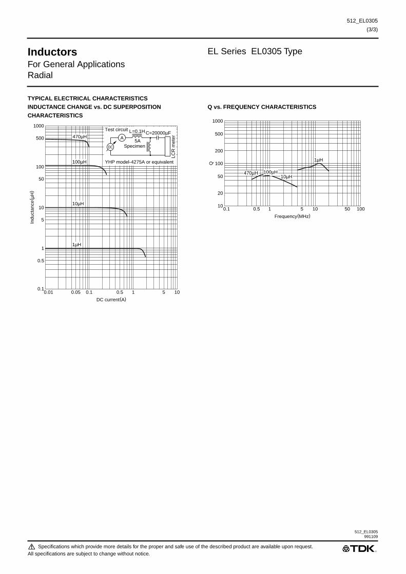
512_EL0305
(3/3)
Inductors
EL Series EL0305 Type
For General ApplicationsRadial
TYPICAL ELECTRICAL CHARACTERISTICSINDUCTANCE CHANGE vs. DC SUPERPOSITIONCHARACTERISTICS
Q vs. FREQUENCY CHARACTERISTICS
DC current(A)0.01
1
0.5
0.1
10
100
50
5
1000
500
0.05 0.1 0.5 51 10
Indu
ctan
ce( µ
H)
470µH
10µH
100µH
1µH
AL=0.1H
5A
C=20000µFTest circuit
DC
LCR
met
er
Specimen
YHP model-4275A or equivalent
Frequency(MHz)0.1 10.5 105
10
20
50
100
200
500
1000
Q10050
1µH
10µH100µH470µH

Specifications which provide more details for the proper and safe use of the described product are available upon request.All specifications are subject to change without notice.
512_EL0405
(1/3)
Inductors
EL Series EL0405 Type
For General ApplicationsRadial
FEATURES
• The EL series inductors are available in 6 form factors ranging
from 0304 to 0909.
• With a miniature winding construction, these inductors
nonetheless achieve high Q characteristics.
• Available in tape packaging to support automated mounting
machines.
APPLICATIONS
Televisions, VCRs, personal computers, and other electronic
equipment.
SPECIFICATIONS
PRODUCT IDENTIFICATION
(1)Series name
(2)Dimensions
(3)Packaging style
(4)Inductance value
(5)Inductance tolerance
(6)TDK internal code
(Some products may not have this number. See the main body
for details.)
PACKAGING STYLE AND QUANTITIES
Operating temperature range –20 to +80°C [Including self-temperature rise]
Storage temperature range –40 to +80°C [Unit of products]Terminal tensile strength EL0304: 4.9N min.
EL0305: 7.84N min.EL0405: 7.84N min.EL0606: 14.7N min.EL0607: 14.7N min.EL0909: 14.7N min.
0304 4
×
3
×
4mm (lead pitch 2.5mm)0305 5
×
3.8
×
5mm (lead pitch 5mm)0405 5.4
×
4.4
×
7mm (lead pitch 5mm)0606 6.4
×
6
×
10mm (lead pitch 5mm)0607 7.4
×
6.2
×
10mm (lead pitch 5mm)0909 9.4
×
9
×
13.5mm (lead pitch 5mm)
RA Ammo-packRR Reel
R22 0.22
µ
H1R0 1
µ
H
J ±5%K ±10%M ±20%
Packaging style Type QuantityAmmo-pack EL0304RA 3000 pieces
EL0305RA 3000 piecesEL0405RA 3000 piecesEL0606RA 2000 piecesEL0607RA 2000 pieces
Taping EL0909RR 500 pieces/reel
EL 0405 RA- 1R0 K -3
(1) (2) (3) (4) (5) (6)

Specifications which provide more details for the proper and safe use of the described product are available upon request.All specifications are subject to change without notice.
512_EL0405
(2/3)
Inductors
EL Series EL0405 Type
For General ApplicationsRadial
AMMO-PACK TAPING STYLESHAPES AND DIMENSIONS CHARACTERISTICS
ELECTRICAL CHARACTERISTICS
∗
X: Please specify inductance tolerance, M(±20%), K(±10%) or J (±5%)
5.4max.
7max
.
(2)
5+0.8, –0.5
4.4max.
ø0.5±0.05
Dimensions in mm
23+
2, –
0
Operating temperature range–20 to +80°C[Including self-temperature rise 20°C max.]
Withistand voltage Erms 250V
Rated current Based on inductance change [–10% to the initial value]
Terminal tensile strength 7.84N min.Moisture resistance
∆
L/L ±5%
∆
Q/Q ±25%
Inductance(µH)
Inductancetolerance
Q min.Test frequencyL, Q(MHz)
Self-resonantfrequency (MHz)min.
DC resistance(
Ω
)max.Rated current(mA)max.
Part No.
0.22 ±20, ±10% 50 25.2 150 0.15 800 EL0405RA-R22X
∗
-3 0.27 ±20, ±10% 50 25.2 150 0.15 800 EL0405RA-R27X-30.33 ±20, ±10% 50 25.2 150 0.15 800 EL0405RA-R33X-30.39 ±20, ±10% 50 25.2 130 0.15 800 EL0405RA-R39X-30.47 ±20, ±10% 50 25.2 130 0.15 800 EL0405RA-R47X-30.56 ±20, ±10% 50 25.2 130 0.2 700 EL0405RA-R56X-30.68 ±20, ±10% 50 25.2 120 0.2 700 EL0405RA-R68X-30.82 ±20, ±10% 50 25.2 120 0.2 700 EL0405RA-R82X-31 ±10, ±5% 50 7.96 85 0.22 674 EL0405RA-1R0X-31.2 ±10, ±5% 50 7.96 75 0.24 645 EL0405RA-1R2X-31.5 ±10, ±5% 50 7.96 65 0.27 608 EL0405RA-1R5X-31.8 ±10, ±5% 50 7.96 55 0.3 577 EL0405RA-1R8X-32.2 ±10, ±5% 50 7.96 50 0.33 550 EL0405RA-2R2X-32.7 ±10, ±5% 50 7.96 45 0.37 520 EL0405RA-2R7X-33.3 ±10, ±5% 50 7.96 40 0.42 488 EL0405RA-3R3X-33.9 ±10, ±5% 50 7.96 35 0.46 466 EL0405RA-3R9X-34.7 ±10, ±5% 50 7.96 30 0.53 434 EL0405RA-4R7X-35.6 ±10, ±5% 50 7.96 27 0.56 422 EL0405RA-5R6X-36.8 ±10, ±5% 50 7.96 25 0.63 398 EL0405RA-6R8X-38.2 ±10, ±5% 50 7.96 22 0.7 378 EL0405RA-8R2X-310 ±10, ±5% 50 2.52 20 0.8 353 EL0405RA-100X-312 ±10, ±5% 50 2.52 18 0.87 339 EL0405RA-120X-315 ±10, ±5% 50 2.52 15 1 316 EL0405RA-150X-318 ±10, ±5% 50 2.52 12 1.11 301 EL0405RA-180X-322 ±10, ±5% 40 2.52 11 1.35 272 EL0405RA-220X-327 ±10, ±5% 40 2.52 10 1.55 254 EL0405RA-270X-333 ±10, ±5% 40 2.52 9.5 1.75 239 EL0405RA-330X-339 ±10, ±5% 40 2.52 9 2 223 EL0405RA-390X-347 ±10, ±5% 40 2.52 8.5 2.2 213 EL0405RA-470X-356 ±10, ±5% 40 2.52 8 2.4 204 EL0405RA-560X-368 ±10, ±5% 40 2.52 7.5 3.3 174 EL0405RA-680X-382 ±10, ±5% 40 2.52 7 3.7 164 EL0405RA-820X-3

512_EL0405991109
Specifications which provide more details for the proper and safe use of the described product are available upon request.All specifications are subject to change without notice.
512_EL0405
(3/3)
Inductors
EL Series EL0405 Type
For General ApplicationsRadial
ELECTRICAL CHARACTERISTICS
∗
X: Please specify inductance tolerance, K(±10%) or J (±5%)
TYPICAL ELECTRICAL CHARACTERISTICSINDUCTANCE CHANGE vs. DC SUPERPOSITIONCHARACTERISTICS
INDUCTANCE CHANGE vs. TEMPERATURECHARACTERISTICS
Q vs. FREQUENCY CHARACTERISTICS
Inductance(µH)
Inductancetolerance
Q min.Test frequencyL, Q(MHz)
Self-resonantfrequency (MHz)min.
DC resistance(
Ω
)max.Rated current(mA)max.
Part No.
100 ±10, ±5% 35 0.796 6.5 4.4 150 EL0405RA-101X
∗
-3120 ±10, ±5% 35 0.796 6.2 5.1 140 EL0405RA-121X-3150 ±10, ±5% 35 0.796 5.7 5.95 130 EL0405RA-151X-3180 ±10, ±5% 35 0.796 5.3 7 120 EL0405RA-181X-3220 ±10, ±5% 35 0.796 4 8 112 EL0405RA-221X-3270 ±10, ±5% 35 0.796 3.6 12.4 90 EL0405RA-271X-3330 ±10, ±5% 35 0.796 3.3 13.2 87 EL0405RA-331X-3390 ±10, ±5% 35 0.796 3 15.4 80 EL0405RA-391X-3470 ±10, ±5% 35 0.796 2.8 17.3 76 EL0405RA-471X-3560 ±10, ±5% 30 0.796 2.4 21 69 EL0405RA-561X-3680 ±10, ±5% 30 0.796 2.2 23.5 65 EL0405RA-681X-3820 ±10, ±5% 30 0.796 2 26.5 61 EL0405RA-821X-31000 ±10, ±5% 25 0.252 1.8 31.5 56 EL0405RA-102X-3
DC current(mA)1
10
5
1
100
1000
500
50
10000
5000
5 10 50 500100 1000
Indu
ctan
ce( µ
H)
150µH
100µH
47µH
18µH
8.2µH
4.7µH
470µH
AL=0.1H
5A
C=20000µFTest circuit
DC
LCR
met
er
Specimen
YHP model-4275A or equivalent
0 20
2
3
1
–2
–3
–1
40 60 80
∆L
/L( %
)
Temperature(°C)–20
47µH
3.3µH
470µH3.3µH
47µH
470µH
Test terminal: Measuring at after the correctionCycle: +20°C → +80°C → +20°C → –20°CTemperature: Kept stabilized for 30+5, –0min each
Measuring frequency3.3µH: 1MHz47µH: 1MHz470µH: 50kHz
Test equipment:LCR METER YHP4275A
Frequency(MHz)0.1 10.5 105
10
20
50
100
200
500
1000
Q
10050
0.47µH4.7µH47µH
470µH
Test equipment: Q METER YHP4340A

Specifications which provide more details for the proper and safe use of the described product are available upon request.All specifications are subject to change without notice.
512_EL0606
(1/4)
Inductors
EL Series EL0606 Type
For General ApplicationsRadial
FEATURES
• The EL series inductors are available in 6 form factors ranging
from 0304 to 0909.
• With a miniature winding construction, these inductors
nonetheless achieve high Q characteristics.
• Available in tape packaging to support automated mounting
machines.
APPLICATIONS
Televisions, VCRs, personal computers, and other electronic
equipment.
SPECIFICATIONS
PRODUCT IDENTIFICATION
(1)Series name
(2)Dimensions
(3)Packaging style
(4)Inductance value
(5)Inductance tolerance
(6)TDK internal code
(Some products may not have this number. See the main body
for details.)
PACKAGING STYLE AND QUANTITIES
Operating temperature range –20 to +80°C [Including self-temperature rise]
Storage temperature range –40 to +80°C [Unit of products]Terminal tensile strength EL0304: 4.9N min.
EL0305: 7.84N min.EL0405: 7.84N min.EL0606: 14.7N min.EL0607: 14.7N min.EL0909: 14.7N min.
0304 4
×
3
×
4mm (lead pitch 2.5mm)0305 5
×
3.8
×
5mm (lead pitch 5mm)0405 5.4
×
4.4
×
7mm (lead pitch 5mm)0606 6.4
×
6
×
10mm (lead pitch 5mm)0607 7.4
×
6.2
×
10mm (lead pitch 5mm)0909 9.4
×
9
×
13.5mm (lead pitch 5mm)
RA Ammo-packRR Reel
R22 0.22
µ
H1R0 1
µ
H
J ±5%K ±10%M ±20%
Packaging style Type QuantityAmmo-pack EL0304RA 3000 pieces
EL0305RA 3000 piecesEL0405RA 3000 piecesEL0606RA 2000 piecesEL0607RA 2000 pieces
Taping EL0909RR 500 pieces/reel
EL 0405 RA- 1R0 K -3
(1) (2) (3) (4) (5) (6)

Specifications which provide more details for the proper and safe use of the described product are available upon request.All specifications are subject to change without notice.
512_EL0606
(2/4)
Inductors
EL Series EL0606 Type
For General ApplicationsRadial
AMMO-PACK TAPING STYLESHAPES AND DIMENSIONS CHARACTERISTICS
ELECTRICAL CHARACTERISTICS
6.4max.
10m
ax.
(2.2)
27.5
max
.
5+0.6, –0.2 Dimensions in mm
6max.
ø0.62+0.03, –0.05
Operating temperature range–20 to +80°C[Including self-temperature rise 20°C max.]
Withistand voltage Erms 250V
Rated current Based on inductance change [–10% to the initial value]
Terminal tensile strength 14.7N min.Moisture resistance
∆
L/L ±5%
∆
Q/Q ±25%
Inductance(µH)
Inductancetolerance
Q min.Test frequencyL, Q(MHz)
Self-resonantfrequency (MHz)min.
DC resistance(
Ω
)max.Rated current(mA)max.
Part No.
0.22 ±10% 50 25.2 150 0.15 816 EL0606RA-R22K0.27 ±10% 50 25.2 150 0.15 816 EL0606RA-R27K0.33 ±10% 50 25.2 150 0.15 816 EL0606RA-R33K0.39 ±10% 50 25.2 130 0.15 816 EL0606RA-R39K0.47 ±10% 50 25.2 130 0.15 816 EL0606RA-R47K0.56 ±10% 50 25.2 130 0.2 707 EL0606RA-R56K0.68 ±10% 50 25.2 120 0.2 707 EL0606RA-R68K0.82 ±10% 50 25.2 120 0.2 707 EL0606RA-R82K1 ±5% 50 7.96 100 0.2 707 EL0606RA-1R0J1.2 ±5% 50 7.96 85 0.2 707 EL0606RA-1R2J1.5 ±5% 50 7.96 70 0.22 674 EL0606RA-1R5J1.8 ±5% 50 7.96 60 0.22 674 EL0606RA-1R8J2.2 ±5% 50 7.96 55 0.25 632 EL0606RA-2R2J2.7 ±5% 50 7.96 50 0.27 608 EL0606RA-2R7J3.3 ±5% 50 7.96 45 0.3 577 EL0606RA-3R3J3.9 ±5% 50 7.96 40 0.32 559 EL0606RA-3R9J4.7 ±5% 50 7.96 35 0.35 534 EL0606RA-4R7J5.6 ±5% 50 7.96 33 0.37 519 EL0606RA-5R6J6.8 ±5% 50 7.96 27 0.4 500 EL0606RA-6R8J8.2 ±5% 50 7.96 25 0.45 471 EL0606RA-8R2J10 ±5% 50 2.52 20 0.8 353 EL0606RA-100J12 ±5% 50 2.52 18 0.9 333 EL0606RA-120J15 ±5% 50 2.52 17 1 316 EL0606RA-150J18 ±5% 50 2.52 15 1.2 288 EL0606RA-180J 22 ±5% 50 2.52 13 1.4 267 EL0606RA-220J27 ±5% 50 2.52 11 1.7 242 EL0606RA-270J33 ±5% 50 2.52 10.5 2 223 EL0606RA-330J39 ±5% 50 2.52 10 2.4 204 EL0606RA-390J47 ±5% 50 2.52 9.5 2.7 192 EL0606RA-470J56 ±5% 50 2.52 9 2.9 185 EL0606RA-560J68 ±5% 50 2.52 8.5 3.1 179 EL0606RA-680J82 ±5% 50 2.52 7.5 3.3 174 EL0606RA-820J100 ±5% 45 0.796 6.8 3.3 174 EL0606RA-101J120 ±5% 45 0.796 6.2 3.5 169 EL0606RA-121J150 ±5% 45 0.796 5.7 3.7 164 EL0606RA-151J180 ±5% 45 0.796 5.3 4 158 EL0606RA-181J

Specifications which provide more details for the proper and safe use of the described product are available upon request.All specifications are subject to change without notice.
512_EL0606
(3/4)
Inductors
EL Series EL0606 Type
For General ApplicationsRadial
ELECTRICAL CHARACTERISTICS
TYPICAL ELECTRICAL CHARACTERISTICSINDUCTANCE CHANGE vs. DC SUPERPOSITIONCHARACTERISTICS
INDUCTANCE CHANGE vs. TEMPERATURECHARACTERISTICS
Inductance(µH)
Inductancetolerance
Q min.Test frequencyL, Q(MHz)
Self-resonantfrequency (MHz)min.
DC resistance(
Ω
)max.Rated current(mA)max.
Part No.
220 ±5% 45 0.796 4 5.2 138 EL0606RA-221J270 ±5% 45 0.796 3.6 5.8 131 EL0606RA-271J330 ±5% 45 0.796 3.3 6.5 124 EL0606RA-331J390 ±5% 45 0.796 3 7.5 115 EL0606RA-391J470 ±5% 45 0.796 2.8 8 111 EL0606RA-471J560 ±5% 45 0.796 2.4 12.5 89 EL0606RA-561J680 ±5% 45 0.796 2.2 14 84 EL0606RA-681J820 ±5% 45 0.796 2 15.5 80 EL0606RA-821J1000 ±5% 40 0.252 1.8 18.5 73 EL0606RA-102J1200 ±5% 30 0.252 1.7 29 58 EL0606RA-122J1500 ±5% 30 0.252 1.5 34 54 EL0606RA-152J1800 ±5% 30 0.252 1.4 37 51 EL0606RA-182J2200 ±5% 30 0.252 1.2 42 48 EL0606RA-222J
DC current(mA)1
10
5
100
1000
500
50
10000
5000
5 10 50 500100 1000
Indu
ctan
ce( µ
H)
82µH
39µH
10µH
330µH
820µH
1800µH
AL=0.1H
5A
C=20000µFTest circuit
DC
LCR
met
er
Specimen
YHP model-4261A or equivalent
0 20
2
5
4
3
1
–2
–3
–4
–5
–1
40 60 80
∆L
/L( %
)
Temperature(°C)
–20
2.2µH
Test terminal: Measuring at after the correctionCycle: +20°C → +85°C → +20°C → –20°CTemperature: Kept stabilized for 30+5, –0min each
6.8µH68µH22µH0.68µH
0.22µH
680µH220µH2200µH2200µH
220µH680µH
0.68µH68µH
0.22µH22µH6.8µH
2.2µH
Measuring frequency0.22 to 0.82µH: 5MHz10 to 82µH: 1MHz100 to 820µH: 500kHz1000 to 2200µH: 100kHz
Test equipment:LCR METER YHP4275A

512_EL0606991109
Specifications which provide more details for the proper and safe use of the described product are available upon request.All specifications are subject to change without notice.
512_EL0606
(4/4)
Inductors
EL Series EL0606 Type
For General ApplicationsRadial
TYPICAL ELECTRICAL CHARACTERISTICSQ vs. FREQUENCY CHARACTERISTICS
Frequency(MHz)0.1 10.5 105
10
20
50
100
200
500
1000
Q
10050
0.47µH4.7µH47µH
820µH
Test equipment: Q METER YHP4340A

Specifications which provide more details for the proper and safe use of the described product are available upon request.All specifications are subject to change without notice.
512_EL0607
(1/3)
Inductors
EL Series EL0607 Type
For General ApplicationsRadial
FEATURES
• The EL series inductors are available in 6 form factors ranging
from 0304 to 0909.
• With a miniature winding construction, these inductors
nonetheless achieve high Q characteristics.
• Available in tape packaging to support automated mounting
machines.
APPLICATIONS
Televisions, VCRs, personal computers, and other electronic
equipment.
SPECIFICATIONS
PRODUCT IDENTIFICATION
(1)Series name
(2)Dimensions
(3)Packaging style
(4)Inductance value
(5)Inductance tolerance
(6)TDK internal code
(Some products may not have this number. See the main body
for details.)
PACKAGING STYLE AND QUANTITIES
Operating temperature range –20 to +80°C [Including self-temperature rise]
Storage temperature range –40 to +80°C [Unit of products]Terminal tensile strength EL0304: 4.9N min.
EL0305: 7.84N min.EL0405: 7.84N min.EL0606: 14.7N min.EL0607: 14.7N min.EL0909: 14.7N min.
0304 4
×
3
×
4mm (lead pitch 2.5mm)0305 5
×
3.8
×
5mm (lead pitch 5mm)0405 5.4
×
4.4
×
7mm (lead pitch 5mm)0606 6.4
×
6
×
10mm (lead pitch 5mm)0607 7.4
×
6.2
×
10mm (lead pitch 5mm)0909 9.4
×
9
×
13.5mm (lead pitch 5mm)
RA Ammo-packRR Reel
R22 0.22
µ
H1R0 1
µ
H
J ±5%K ±10%M ±20%
Packaging style Type QuantityAmmo-pack EL0304RA 3000 pieces
EL0305RA 3000 piecesEL0405RA 3000 piecesEL0606RA 2000 piecesEL0607RA 2000 pieces
Taping EL0909RR 500 pieces/reel
EL 0405 RA- 1R0 K -3
(1) (2) (3) (4) (5) (6)

Specifications which provide more details for the proper and safe use of the described product are available upon request.All specifications are subject to change without notice.
512_EL0607
(2/3)
Inductors
EL Series EL0607 Type
For General ApplicationsRadial
AMMO-PACK TAPING STYLESHAPES AND DIMENSIONS CHARACTERISTICS
ELECTRICAL CHARACTERISTICS
∗
X: Please specify inductance tolerance, K(±10%) or J(±5%)
10m
ax.
(2.5)
27.5
max
.
5+0.6, –0.2 Dimensions in mm
6.2max.
ø0.62+0.03, –0.05
7.4+0.6
Operating temperature range–20 to +80°C[Including self-temperature rise 20°C max.]
Withistand voltage Erms 250V
Rated current Based on inductance change [–10% to the initial value]
Terminal tensile strength 14.7N min.Moisture resistance
∆
L/L ±5%
∆
Q/Q ±25%
Inductance(µH)
Inductancetolerance
Q min.Test frequencyL, Q(MHz)
Self-resonantfrequency (MHz)min.
DC resistance(
Ω
)max.Rated current(mA)max.
Part No.
10 ±10, ±5% 20 2.52 17 0.19 780 EL0607RA-100X
∗
12 ±10, ±5% 20 2.52 14 0.22 730 EL0607RA-120X15 ±10, ±5% 20 2.52 12 0.24 650 EL0607RA-150X18 ±10, ±5% 20 2.52 10.5 0.26 610 EL0607RA-180X22 ±10, ±5% 20 2.52 10 0.29 540 EL0607RA-220X27 ±10, ±5% 20 2.52 9.5 0.32 480 EL0607RA-270X33 ±10, ±5% 20 2.52 8.5 0.34 440 EL0607RA-330X39 ±10, ±5% 20 2.52 8 0.42 410 EL0607RA-390X47 ±10, ±5% 20 2.52 7 0.47 375 EL0607RA-470X56 ±10, ±5% 20 2.52 6.8 0.52 340 EL0607RA-560X68 ±10, ±5% 15 2.52 6.5 0.58 320 EL0607RA-680X82 ±10, ±5% 15 2.52 6.3 0.64 285 EL0607RA-820X100 ±10, ±5% 25 0.796 6 0.85 260 EL0607RA-101X120 ±10, ±5% 25 0.796 5.4 1 240 EL0607RA-121X150 ±10, ±5% 25 0.796 4.75 1.2 215 EL0607RA-151X180 ±10, ±5% 30 0.796 4 1.5 195 EL0607RA-181X220 ±10, ±5% 30 0.796 3.85 1.65 180 EL0607RA-221X270 ±10, ±5% 30 0.796 3.6 2.15 160 EL0607RA-271X330 ±10, ±5% 35 0.796 3.3 2.9 145 EL0607RA-331X390 ±10, ±5% 35 0.796 3 3.25 135 EL0607RA-391X470 ±10, ±5% 35 0.796 2.8 4.05 125 EL0607RA-471X560 ±10, ±5% 40 0.796 2.4 4.45 115 EL0607RA-561X680 ±10, ±5% 40 0.796 2.2 5.85 105 EL0607RA-681X820 ±10, ±5% 40 0.796 2 6.6 90 EL0607RA-821X1000 ±10, ±5% 45 0.252 1.8 8.9 85 EL0607RA-102X1200 ±10, ±5% 45 0.252 1.7 10.5 75 EL0607RA-122X1500 ±10, ±5% 45 0.252 1.5 11.9 70 EL0607RA-152X1800 ±10, ±5% 45 0.252 1.3 16.5 60 EL0607RA-182X2200 ±10, ±5% 45 0.252 1.2 19 58 EL0607RA-222X2700 ±10, ±5% 40 0.252 0.8 32 52 EL0607RA-272X

512_EL0607991109
Specifications which provide more details for the proper and safe use of the described product are available upon request.All specifications are subject to change without notice.
512_EL0607
(3/3)
Inductors
EL Series EL0607 Type
For General ApplicationsRadial
ELECTRICAL CHARACTERISTICS
∗
X: Please specify inductance tolerance, K(±10%) or J(±5%)
TYPICAL ELECTRICAL CHARACTERISTICSINDUCTANCE CHANGE vs. DC SUPERPOSITIONCHARACTERISTICS
INDUCTANCE CHANGE vs. TEMPERATURECHARACTERISTICS
Q vs. FREQUENCY CHARACTERISTICS
Inductance(µH)
Inductancetolerance
Q min.Test frequencyL, Q(MHz)
Self-resonantfrequency (MHz)min.
DC resistance(
Ω
)max.Rated current(mA)max.
Part No.
3300 ±10, ±5% 40 0.252 0.7 34 48 EL0607RA-332X
∗
3900 ±10, ±5% 40 0.252 0.7 38 45 EL0607RA-392X 4700 ±10, ±5% 40 0.252 0.6 56 40 EL0607RA-472X 5600 ±10, ±5% 40 0.252 0.5 63 37 EL0607RA-562X6800 ±10, ±5% 40 0.252 0.4 70 34 EL0607RA-682X 8200 ±10, ±5% 40 0.252 0.4 77 31 EL0607RA-822X10000 ±10, ±5% 25 0.0796 0.3 95 28 EL0607RA-103X12000 ±10, ±5% 25 0.0796 0.2 110 25 EL0607RA-123X 15000 ±10, ±5% 20 0.0796 0.1 160 21 EL0607RA-153X
DC current(mA)1
10
100
1000
500
50
10000
5000
100000
50000
5 10 50 500100 1000
Indu
ctan
ce( µ
H)
330µH
100µH
1000µH
8200µH
3300µH
AL=0.1H
5A
C=20000µFTest circuit
DC
LCR
met
er
Specimen
YHP model-4261A or equivalent
0 20
2
3
1
–2
–3
–1
40 60 80
∆L
/L( %
)
Temperature(°C)–20
Test terminal: Measuring at after the correctionCycle: +20°C → +85°C → +20°C → –20°CTemperature: Kept stabilized for 30+5, –0min each
3300µH6800µH
3300µH6800µH
Test frequency3300µH: 100kHz6800µH: 100kHz
Test equipment:LCR METER YHP4275A
Frequency(MHz)0.1 10.5 105
10
20
50
100
200
500
1000
Q
10050
47µH
820µH6800µH
Test equipment: Q METER YHP4340A

Specifications which provide more details for the proper and safe use of the described product are available upon request.All specifications are subject to change without notice.
512_EL0909
(1/3)
Inductors
EL Series EL0909 Type
For General ApplicationsRadial
FEATURES
• The EL series inductors are available in 6 form factors ranging
from 0304 to 0909.
• With a miniature winding construction, these inductors
nonetheless achieve high Q characteristics.
• Available in tape packaging to support automated mounting
machines.
APPLICATIONS
Televisions, VCRs, personal computers, and other electronic
equipment.
SPECIFICATIONS
PRODUCT IDENTIFICATION
(1)Series name
(2)Dimensions
(3)Packaging style
(4)Inductance value
(5)Inductance tolerance
(6)TDK internal code
(Some products may not have this number. See the main body
for details.)
PACKAGING STYLE AND QUANTITIES
Operating temperature range –20 to +80°C [Including self-temperature rise]
Storage temperature range –40 to +80°C [Unit of products]Terminal tensile strength EL0304: 4.9N min.
EL0305: 7.84N min.EL0405: 7.84N min.EL0606: 14.7N min.EL0607: 14.7N min.EL0909: 14.7N min.
0304 4
×
3
×
4mm (lead pitch 2.5mm)0305 5
×
3.8
×
5mm (lead pitch 5mm)0405 5.4
×
4.4
×
7mm (lead pitch 5mm)0606 6.4
×
6
×
10mm (lead pitch 5mm)0607 7.4
×
6.2
×
10mm (lead pitch 5mm)0909 9.4
×
9
×
13.5mm (lead pitch 5mm)
RA Ammo-packRR Reel
R22 0.22
µ
H1R0 1
µ
H
J ±5%K ±10%M ±20%
Packaging style Type QuantityAmmo-pack EL0304RA 3000 pieces
EL0305RA 3000 piecesEL0405RA 3000 piecesEL0606RA 2000 piecesEL0607RA 2000 pieces
Taping EL0909RR 500 pieces/reel
EL 0405 RA- 1R0 K -3
(1) (2) (3) (4) (5) (6)

Specifications which provide more details for the proper and safe use of the described product are available upon request.All specifications are subject to change without notice.
512_EL0909
(2/3)
Inductors
EL Series EL0909 Type
For General ApplicationsRadial
REEL TAPING STYLESHAPES AND DIMENSIONS CHARACTERISTICS
ELECTRICAL CHARACTERISTICS
∗
1
X: Please specify inductance tolerance, K(±10%) or J(±5%)
∗
2
for L
∗
3
for Q
13.5
max
.
(2.5)
30m
ax.
5+0.8, –0.2 Dimensions in mm
ø0.62+0.03, –0.05
9.4max.9.4+0.6
Operating temperature range–20 to +80°C[Including self-temperature rise 20°C max.]
Withistand voltage Erms 250V
Rated current Based on inductance change [–10% to the initial value]
Terminal tensile strength 14.7N min.Moisture resistance
∆
L/L ±5%
∆
Q/Q ±25%
Inductance(µH)
Inductancetolerance
Q min.Test frequencyL, Q(MHz)
Self-resonantfrequency (MHz)min.
DC resistance(
Ω
)max.Rated current(mA)max.
Part No.
100 ±10, ±5% 55 796 4.3 0.85 343 EL0909RR-101X
∗
1
-2120 ±10, ±5% 55 796 4.1 0.95 324 EL0909RR-121X-2150 ±10, ±5% 55 796 3.7 1.05 309 EL0909RR-151X-2180 ±10, ±5% 55 796 3.3 1.15 295 EL0909RR-181X-2220 ±10, ±5% 50 796 2.3 1.3 277 EL0909RR-221X-2270 ±10, ±5% 50 796 2 1.5 258 EL0909RR-271X-2330 ±10, ±5% 50 796 1.95 1.7 243 EL0909RR-331X-2390 ±10, ±5% 50 796 1.85 1.85 232 EL0909RR-391X-2470 ±10, ±5% 50 796 1.57 2.3 209 EL0909RR-471X-2560 ±10, ±5% 45 796 1.5 2.55 198 EL0909RR-561X-2680 ±10, ±5% 40 796 1.4 2.85 187 EL0909RR-681X-2820 ±10, ±5% 35 796 1.32 3.1 180 EL0909RR-821X-21000 ±10, ±5% 60 252 1.25 4.1 156 EL0909RR-102X-21200 ±10, ±5% 60 252 1.2 4.7 146 EL0909RR-122X-21500 ±10, ±5% 60 252 1 5.8 131 EL0909RR-152X-21800 ±10, ±5% 60 252 0.95 7.4 116 EL0909RR-182X-22200 ±10, ±5% 65 252 0.9 8.4 109 EL0909RR-222X-22700 ±10, ±5% 65 252 0.84 11.2 94 EL0909RR-272X-23300 ±10, ±5% 65 252 0.75 14.7 82 EL0909RR-332X-23900 ±10, ±5% 65 252 0.67 19.5 72 EL0909RR-392X-24700 ±10, ±5% 65 252 0.62 21.5 68 EL0909RR-472X-25600 ±10, ±5% 60 252 0.57 24.5 64 EL0909RR-562X-26800 ±10, ±5% 60 252 0.47 32.5 55 EL0909RR-682X-28200 ±10, ±5% 55 252 0.43 38 51 EL0909RR-822X-210000 ±10, ±5% 50 1
∗
2
/79.6
∗
3
0.38 43 48 EL0909RR-103X-212000 ±10, ±5% 50 1/79.6 0.37 62 40 EL0909RR-123X-215000 ±10, ±5% 50 1/79.6 0.33 74 37 EL0909RR-153X-218000 ±10, ±5% 50 1/79.6 0.29 103 31 EL0909RR-183X-222000 ±10, ±5% 50 1/79.6 0.26 118 29 EL0909RR-223X-227000 ±10, ±5% 50 1/79.6 0.25 131 28 EL0909RR-273X-233000 ±10, ±5% 50 1/79.6 0.25 185 23 EL0909RR-333X-239000 ±10, ±5% 40 1/79.6 0.23 205 22 EL0909RR-393X-247000 ±10, ±5% 35 1/79.6 0.21 260 20 EL0909RR-473X-256000 ±10, ±5% 35 1/79.6 0.2 295 18 EL0909RR-563X-2

512_EL0909991109
Specifications which provide more details for the proper and safe use of the described product are available upon request.All specifications are subject to change without notice.
512_EL0909
(3/3)
Inductors
EL Series EL0909 Type
For General ApplicationsRadial
TYPICAL ELECTRICAL CHARACTERISTICSINDUCTANCE CHANGE vs. DC SUPERPOSITIONCHARACTERISTICS
Q vs. FREQUENCY CHARACTERISTICS
DC current(mA)10
10
100
1000
500
50
100000
50000
10000
5000
50 100 500 50001000 10000
Indu
ctan
ce( µ
H)
120µH
330µH
1200µH
5600µH
AL=0.1H
5A
C=20000µFTest circuit
DC
LCR
met
er
Specimen
YHP model-4261A or equivalent
Frequency(kHz)10 10050 1000500
10
20
50
100
200
500
1000
Q100005000
1200µH
5600µH
33000µH
Test equipment: Q METER YHP4340A

Specifications which provide more details for the proper and safe use of the described product are available upon request.All specifications are subject to change without notice.
512_ELF0505
(1/3)
Inductors
ELF Series ELF0505 Type
For General ApplicationsRadial
FEATURES
• The ELF series inductors are available in 4 form factors ranging
from 0505 to 1010.
• Because they are magnetically shielded, these parts can be
used in high-density mounting configurations.
• With a miniature winding construction, these inductors
nonetheless achieve high Q characteristics.
• Available in tape packaging to support automated mounting
machines.
APPLICATIONS
Televisions, VCRs, personal computers, and other electronic
equipment.
SPECIFICATIONS
PRODUCT IDENTIFICATION
(1)Series name
(2)Dimensions
(3)Packaging style
(4)Inductance value
(5)Inductance tolerance
(6)TDK internal code
(Some products may not have this number. See the main body
for details.)
PACKAGING STYLE AND QUANTITIES
Operating temperature range–20 to +80°C [Including self-temperature rise]
Storage temperature range –40 to +80°C [Unit of products]Terminal tensile strength 24.5N min.
0505 ø5.5
×
5.5mm (lead pitch 5mm)0607 ø6.6
×
7mm (lead pitch 5mm)0708 ø7.7
×
8mm (lead pitch 5mm)1010 ø10.5
×
10.5mm (lead pitch 5mm)
RA Ammo-packRR Reel
R22 0.22
µ
H1R0 1
µ
H
J ±5%K ±10%M ±20%
Packaging style Type QuantityAmmo-pack ELF0505RA 2000 pieces
ELF0607RA 1000 piecesELF0708RA 1000 pieces
Taping ELF1010RR 300 pieces/reel
ELF 0505 RA- 1R0 K -3
(1) (2) (3) (4) (5) (6)

Specifications which provide more details for the proper and safe use of the described product are available upon request.All specifications are subject to change without notice.
512_ELF0505
(2/3)
Inductors
ELF Series ELF0505 Type
For General ApplicationsRadial
AMMO-PACK TAPING STYLESHAPES AND DIMENSIONS
ELECTRICAL CHARACTERISTICS
∗
1
Rated current: Value obtained when current flows and the temperature has risen to 20°C or when DC current flows and the initial value of inductance has fallen by 10%, whichever is smaller.
∗
2
X: Please specify inductance tolerance, M(±20%) or K(±10%) or J(±5%)• Test equipment L, Q: YHP4340A Q METER, or equivalent
Rdc: MATSUSHITA VP-2941A DIGITAL MILLIOHM METER, or equivalentSRF: TAKEDA RIKEN TR-4100 TRACKING SCOPE, or equivalent
Inductance(µH)
Inductancetolerance
Q min.TestfrequencyL, Q (MHz)
Self-resonantfrequency(MHz)ref.
DC resistance(
Ω
)max.
Rated current (mA)
∗
1
max.
Part No.Based on inductancechange
Based ontemperature rise
0.22 ±20, ±10% 45 25.2 500 0.15 600 895 ELF0505RA-R22X
∗
2
-30.27 ±20, ±10% 45 25.2 470 0.15 600 895 ELF0505RA-R27X-30.33 ±20, ±10% 45 25.2 340 0.15 600 895 ELF0505RA-R33X-30.39 ±20, ±10% 45 25.2 290 0.15 600 895 ELF0505RA-R39X-30.47 ±20, ±10% 45 25.2 250 0.15 600 895 ELF0505RA-R47X-30.56 ±20, ±10% 45 25.2 210 0.15 600 895 ELF0505RA-R56X-30.68 ±20, ±10% 45 25.2 180 0.15 600 895 ELF0505RA-R68X-30.82 ±20, ±10% 45 25.2 135 0.15 600 895 ELF0505RA-R82X-31 ±20, ±10% 50 7.96 125 0.15 600 895 ELF0505RA-1R0X-31.2 ±20, ±10% 50 7.96 110 0.16 600 865 ELF0505RA-1R2X-31.5 ±20, ±10% 50 7.96 99 0.19 600 795 ELF0505RA-1R5X-31.8 ±20, ±10% 50 7.96 88 0.2 600 775 ELF0505RA-1R8X-32.2 ±20, ±10% 50 7.96 79 0.23 600 720 ELF0505RA-2R2X-32.7 ±20, ±10% 50 7.96 70 0.26 600 680 ELF0505RA-2R7X-33.3 ±20, ±10% 50 7.96 63 0.29 600 645 ELF0505RA-3R3X-33.9 ±20, ±10% 50 7.96 58 0.32 590 610 ELF0505RA-3R9X-34.7 ±20, ±10% 50 7.96 53 0.36 540 575 ELF0505RA-4R7X-35.6 ±20, ±10% 40 7.96 49 0.4 500 550 ELF0505RA-5R6X-36.8 ±20, ±10% 40 7.96 45 0.44 455 520 ELF0505RA-6R8X-38.2 ±20, ±10% 35 7.96 41 0.5 395 490 ELF0505RA-8R2X-310 ±10, ±5% 50 2.52 37 0.8 380 385 ELF0505RA-100X-312 ±10, ±5% 50 2.52 34 0.89 350 365 ELF0505RA-120X-315 ±10, ±5% 50 2.52 31 1.02 320 345 ELF0505RA-150X-318 ±10, ±5% 50 2.52 28 1.14 290 325 ELF0505RA-180X-322 ±10, ±5% 50 2.52 25 1.3 265 305 ELF0505RA-220X-327 ±10, ±5% 50 2.52 23 1.46 240 285 ELF0505RA-270X-333 ±10, ±5% 50 2.52 21 1.65 220 270 ELF0505RA-330X-339 ±10, ±5% 50 2.52 19 1.83 200 255 ELF0505RA-390X-347 ±10, ±5% 45 2.52 17.5 2.05 185 240 ELF0505RA-470X-356 ±10, ±5% 50 2.52 16 2.3 170 230 ELF0505RA-560X-3
5.5m
ax.
8.5m
ax.
25m
ax.
5+0.8, –0.1 Dimensions in mm
ø0.5±0.05
ø5.5+0.5
121J

512_ELF0505991109
Specifications which provide more details for the proper and safe use of the described product are available upon request.All specifications are subject to change without notice.
512_ELF0505
(3/3)
Inductors
ELF Series ELF0505 Type
For General ApplicationsRadial
ELECTRICAL CHARACTERISTICS
∗
1
Rated current: Value obtained when current flows and the temperature has risen to 20°C or when DC current flows and the initial value of inductance has fallen by 10%, whichever is smaller.
∗
2
X: Please specify inductance tolerance, K(±10%) or J(±5%)• Test equipment L, Q: YHP4340A Q METER, or equivalent
Rdc: MATSUSHITA VP-2941A DIGITAL MILLIOHM METER, or equivalentSRF: TAKEDA RIKEN TR-4100 TRACKING SCOPE, or equivalent
TYPICAL ELECTRICAL CHARACTERISTICSINDUCTANCE CHANGE vs. DC SUPERPOSITIONCHARACTERISTICS
INDUCTANCE CHANGE vs. TEMPERATURECHARACTERISTICS
Q vs. FREQUENCY CHARACTERISTICS
Inductance(µH)
Inductancetolerance
Q min.TestfrequencyL, Q (MHz)
Self-resonantfrequency(MHz)ref.
DC resistance(
Ω
)max.
Rated current (mA)
∗
1
max.
Part No.Based on inductancechange
Based ontemperature rise
68 ±10, ±5% 45 2.52 14.5 2.6 155 215 ELF0505RA-680X
∗
2
382 ±10, ±5% 45 2.52 13 3.1 145 195 ELF0505RA-820X-3100 ±10, ±5% 40 0.796 12 3.3 130 190 ELF0505RA-101X-3120 ±10, ±5% 40 0.796 11 4.7 120 160 ELF0505RA-121X-3150 ±10, ±5% 40 0.796 10 5.4 108 150 ELF0505RA-151X-3180 ±10, ±5% 40 0.796 9.2 5.6 99 145 ELF0505RA-181X-3220 ±10, ±5% 40 0.796 8.4 6.9 90 130 ELF0505RA-221X-3270 ±10, ±5% 40 0.796 7.6 7.8 82 125 ELF0505RA-271X-3330 ±10, ±5% 40 0.796 6.9 8.9 75 115 ELF0505RA-331X-3390 ±10, ±5% 40 0.796 6.4 13 69 96 ELF0505RA-391X-3470 ±10, ±5% 40 0.796 5.8 14.8 63 90 ELF0505RA-471X-3560 ±10, ±5% 40 0.796 5.3 16.5 58 85 ELF0505RA-561X-3680 ±10, ±5% 40 0.796 5 18.5 53 81 ELF0505RA-681X-3820 ±10, ±5% 40 0.796 4.7 26 48 68 ELF0505RA-821X-31000 ±10, ±5% 30 0.252 4.4 31 44 62 ELF0505RA-102X-31200 ±10, ±5% 30 0.252 4.1 37 40 57 ELF0505RA-122X-3
DC current(mA)1 5 10 50 500100 1000
1
0.5
0.1
10
100
50
5
1000
500
Indu
ctan
ce( µ
H)
1000µH
330µH
100µH
33µH
10µH
3.3µH
0.56µH
AL=5HC=20000µFTest circuit
DC
LCR
met
er
Specimen
–20 0 20
4
6
2
–4
–6
–2
40 60 80
∆L
/L( %
)
Temperature(°C)
YHP 4275A LCR METERf=10kHz
1000µH
1000µH100µH
6.8µH10µH33µH
100µH
33µH10µH
6.8µH
20
40
60
80
100
120
140
Q
Frequency(MHz)0.02 0.1 0.20.05 1 2 5 100.5 5020
2.2µH100µH
1200µH
Q-METER 4340A YHP

Specifications which provide more details for the proper and safe use of the described product are available upon request.All specifications are subject to change without notice.
512_ELF0607
(1/3)
Inductors
ELF Series ELF0607 Type
For General ApplicationsRadial
FEATURES
• The ELF series inductors are available in 4 form factors ranging
from 0505 to 1010.
• Because they are magnetically shielded, these parts can be
used in high-density mounting configurations.
• With a miniature winding construction, these inductors
nonetheless achieve high Q characteristics.
• Available in tape packaging to support automated mounting
machines.
APPLICATIONS
Televisions, VCRs, personal computers, and other electronic
equipment.
SPECIFICATIONS
PRODUCT IDENTIFICATION
(1)Series name
(2)Dimensions
(3)Packaging style
(4)Inductance value
(5)Inductance tolerance
(6)TDK internal code
(Some products may not have this number. See the main body
for details.)
PACKAGING STYLE AND QUANTITIES
Operating temperature range–20 to +80°C [Including self-temperature rise]
Storage temperature range –40 to +80°C [Unit of products]Terminal tensile strength 24.5N min.
0505 ø5.5
×
5.5mm (lead pitch 5mm)0607 ø6.6
×
7mm (lead pitch 5mm)0708 ø7.7
×
8mm (lead pitch 5mm)1010 ø10.5
×
10.5mm (lead pitch 5mm)
RA Ammo-packRR Reel
R22 0.22
µ
H1R0 1
µ
H
J ±5%K ±10%M ±20%
Packaging style Type QuantityAmmo-pack ELF0505RA 2000 pieces
ELF0607RA 1000 piecesELF0708RA 1000 pieces
Taping ELF1010RR 300 pieces/reel
ELF 0505 RA- 1R0 K -3
(1) (2) (3) (4) (5) (6)

Specifications which provide more details for the proper and safe use of the described product are available upon request.All specifications are subject to change without notice.
512_ELF0607
(2/3)
Inductors
ELF Series ELF0607 Type
For General ApplicationsRadial
AMMO-PACK TAPING STYLESHAPES AND DIMENSIONS
ELECTRICAL CHARACTERISTICS
∗
1
Rated current: Value obtained when current flows and the temperature has risen to 20°C or when DC current flows and the initial value of inductance has fallen by 10%, whichever is smaller.
∗
2
X: Please specify inductance tolerance, M(±20%), K(±10%) or J(±5%)• Test equipment L, Q: YHP4340A Q METER, or equivalent
Rdc: MATSUSHITA VP-2941A DIGITAL MILLIOHM METER, or equivalentSRF: TAKEDA RIKEN TR-4100 TRACKING SCOPE, or equivalent
Inductance(µH)
Inductancetolerance
Q min.TestfrequencyL, Q (MHz)
Self-resonantfrequency(MHz)ref.
DC resistance(
Ω
)max.
Rated current (mA)
∗
1
max.
Part No.Based on inductancechange
Based ontemperature rise
0.22 ±20, ±10% 40 25.2 390 0.15 3200 895 ELF0607RA-R22X
∗
2
0.27 ±20, ±10% 40 25.2 330 0.15 2900 895 ELF0607RA-R27X0.33 ±20, ±10% 40 25.2 280 0.15 2600 895 ELF0607RA-R33X0.39 ±20, ±10% 40 25.2 250 0.15 2400 895 ELF0607RA-R39X0.47 ±20, ±10% 40 25.2 220 0.15 2200 895 ELF0607RA-R47X0.56 ±20, ±10% 40 25.2 190 0.15 2100 895 ELF0607RA-R56X0.68 ±20, ±10% 40 25.2 170 0.15 1900 895 ELF0607RA-R68X0.82 ±20, ±10% 40 25.2 140 0.15 1700 895 ELF0607RA-R82X1 ±20, ±10% 45 7.96 120 0.17 1600 840 ELF0607RA-1R0X1.2 ±20, ±10% 50 7.96 110 0.18 1500 815 ELF0607RA-1R2X1.5 ±20, ±10% 50 7.96 90 0.2 1300 775 ELF0607RA-1R5X1.8 ±20, ±10% 50 7.96 80 0.22 1200 740 ELF0607RA-1R8X2.2 ±20, ±10% 50 7.96 68 0.25 1100 690 ELF0607RA-2R2X2.7 ±20, ±10% 50 7.96 58 0.28 1000 655 ELF0607RA-2R7X3.3 ±20, ±10% 50 7.96 50 0.31 930 622 ELF0607RA-3R3X3.9 ±20, ±10% 50 7.96 47 0.34 860 595 ELF0607RA-3R9X4.7 ±20, ±10% 50 7.96 42 0.37 790 570 ELF0607RA-4R7X5.6 ±20, ±10% 50 7.96 39 0.4 730 545 ELF0607RA-5R6X6.8 ±20, ±10% 50 7.96 35 0.45 660 515 ELF0607RA-6R8X8.2 ±20, ±10% 50 7.96 32 0.52 580 480 ELF0607RA-8R2X10 ±10, ±5% 50 2.52 29 0.55 560 465 ELF0607RA-100X12 ±10, ±5% 60 2.52 26 0.97 520 350 ELF0607RA-120X15 ±10, ±5% 60 2.52 23 1.1 470 330 ELF0607RA-150X18 ±10, ±5% 60 2.52 21 1.2 430 315 ELF0607RA-180X22 ±10, ±5% 60 2.52 19 1.3 390 300 ELF0607RA-220X27 ±10, ±5% 60 2.52 17 1.5 360 285 ELF0607RA-270X33 ±10, ±5% 60 2.52 16 1.7 330 265 ELF0607RA-330X39 ±10, ±5% 60 2.52 14 1.8 300 255 ELF0607RA-390X47 ±10, ±5% 60 2.52 13 2.1 270 240 ELF0607RA-470X56 ±10, ±5% 60 2.52 12 2.3 250 230 ELF0607RA-560X
7max
.10
.5m
ax.
27.5
max
.
5+0.8, –0.2 Dimensions in mm
ø0.62±0.05
ø6.6max.
271J

512_ELF0607991109
Specifications which provide more details for the proper and safe use of the described product are available upon request.All specifications are subject to change without notice.
512_ELF0607
(3/3)
Inductors
ELF Series ELF0607 Type
For General ApplicationsRadial
ELECTRICAL CHARACTERISTICS
∗
1
Rated current: Value obtained when current flows and the temperature has risen to 20°C or when DC current flows and the initial value of inductance has fallen by 10%, whichever is smaller.
∗
2
X: Please specify inductance tolerance, K(±10%) or J(±5%)• Test equipment L, Q: YHP4340A Q METER, or equivalent
Rdc: MATSUSHITA VP-2941A DIGITAL MILLIOHM METER, or equivalentSRF: TAKEDA RIKEN TR-4100 TRACKING SCOPE, or equivalent
TYPICAL ELECTRICAL CHARACTERISTICSINDUCTANCE CHANGE vs. DC SUPERPOSITIONCHARACTERISTICS
INDUCTANCE CHANGE vs. TEMPERATURECHARACTERISTICS
Q vs. FREQUENCY CHARACTERISTICS
Inductance(µH)
Inductancetolerance
Q min.TestfrequencyL, Q (MHz)
Self-resonantfrequency(MHz)ref.
DC resistance(
Ω
)max.
Rated current (mA)
∗
1
max.
Part No.Based on inductancechange
Based ontemperature rise
68 ±10, ±5% 60 2.52 11 2.5 230 220 ELF0607RA-680X82 ±10, ±5% 60 2.52 9.8 2.8 210 205 ELF0607RA-820X100 ±10, ±5% 55 0.796 8.9 3.1 200 195 ELF0607RA-101X120 ±10, ±5% 40 0.796 8 3.4 175 185 ELF0607RA-121X150 ±10, ±5% 40 0.796 7.2 3.9 165 175 ELF0607RA-151X180 ±10, ±5% 40 0.796 6.6 4.3 150 165 ELF0607RA-181X220 ±10, ±5% 40 0.796 6 4.7 140 160 ELF0607RA-221X270 ±10, ±5% 40 0.796 5.3 5.3 125 150 ELF0607RA-271X330 ±10, ±5% 40 0.796 4.8 6 115 140 ELF0607RA-331X390 ±10, ±5% 40 0.796 4.4 6.6 105 135 ELF0607RA-391X470 ±10, ±5% 40 0.796 4 7.4 97 125 ELF0607RA-471X560 ±10, ±5% 40 0.796 3.8 8.3 90 120 ELF0607RA-561X680 ±10, ±5% 40 0.796 3.5 13.5 82 94 ELF0607RA-681X820 ±10, ±5% 40 0.796 3.2 15.5 75 88 ELF0607RA-821X1000 ±10, ±5% 30 0.252 2.9 18 68 82 ELF0607RA-102X1200 ±10, ±5% 30 0.252 2.7 21 63 76 ELF0607RA-122X1500 ±10, ±5% 30 0.252 2.4 25 57 69 ELF0607RA-152X1800 ±10, ±5% 30 0.252 2.2 29 52 64 ELF0607RA-182X2200 ±10, ±5% 30 0.252 2 34 48 59 ELF0607RA-222X2700 ±10, ±5% 30 0.252 1.8 40 43 55 ELF0607RA-272X
10
5
1
100
1000
500
50
10000
5000
DC current(mA)1 5 10 50 500100 1000
Indu
ctan
ce( µ
H)
2700µH
1000µH
330µH
100µH
10µH
3.9µH
33µH
AL=5HC=20000µFTest circuit
DC
LCR
met
er
Specimen
–20 0 20
4
6
2
0
–4
–6
–2
40 60 80
∆L
/L( %
)
Temperature(°C)
YHP 4275A LCR METERf=10kHz
2700µH
1000µH330µH
2
330µH1000µH
2700µH
100µH33µH6.8µH
33µH6.8µH
100µH
20
40
60
80
100
120
140
Q
Frequency(MHz)0.02 0.1 0.20.05 1 2 5 100.5 5020
2.2µH100µH
2700µH
Q-METER 4340A YHP

Specifications which provide more details for the proper and safe use of the described product are available upon request.All specifications are subject to change without notice.
512_ELF0708
(1/3)
Inductors
ELF Series ELF0708 Type
For General ApplicationsRadial
FEATURES
• The ELF series inductors are available in 4 form factors ranging
from 0505 to 1010.
• Because they are magnetically shielded, these parts can be
used in high-density mounting configurations.
• With a miniature winding construction, these inductors
nonetheless achieve high Q characteristics.
• Available in tape packaging to support automated mounting
machines.
APPLICATIONS
Televisions, VCRs, personal computers, and other electronic
equipment.
SPECIFICATIONS
PRODUCT IDENTIFICATION
(1)Series name
(2)Dimensions
(3)Packaging style
(4)Inductance value
(5)Inductance tolerance
(6)TDK internal code
(Some products may not have this number. See the main body
for details.)
PACKAGING STYLE AND QUANTITIES
Operating temperature range–20 to +80°C [Including self-temperature rise]
Storage temperature range –40 to +80°C [Unit of products]Terminal tensile strength 24.5N min.
0505 ø5.5
×
5.5mm (lead pitch 5mm)0607 ø6.6
×
7mm (lead pitch 5mm)0708 ø7.7
×
8mm (lead pitch 5mm)1010 ø10.5
×
10.5mm (lead pitch 5mm)
RA Ammo-packRR Reel
R22 0.22
µ
H1R0 1
µ
H
J ±5%K ±10%M ±20%
Packaging style Type QuantityAmmo-pack ELF0505RA 2000 pieces
ELF0607RA 1000 piecesELF0708RA 1000 pieces
Taping ELF1010RR 300 pieces/reel
ELF 0505 RA- 1R0 K -3
(1) (2) (3) (4) (5) (6)

Specifications which provide more details for the proper and safe use of the described product are available upon request.All specifications are subject to change without notice.
512_ELF0708
(2/3)
Inductors
ELF Series ELF0708 Type
For General ApplicationsRadial
AMMO-PACK TAPING STYLESHAPES AND DIMENSIONS
ELECTRICAL CHARACTERISTICS
∗
1
Rated current: Value obtained when current flows and the temperature has risen to 20°C or when DC current flows and the initial value of inductance has fallen by 10%, whichever is smaller.
∗
2
X: Please specify inductance tolerance, K(±10%) or J(±5%)• Test equipment L, Q: YHP4340A Q METER, or equivalent
L (Measurement frequency 1kHz): YHP4261A LCR METER or equivalentRdc: MATSUSHITA VP-2941A DIGITAL MILLIOHM METER, or equivalentSRF: TAKEDA RIKEN TR-4100 TRACKING SCOPE, or equivalent
Inductance(µH)
Inductancetolerance
Q min.TestfrequencyL, Q (MHz)
Self-resonantfrequency(MHz)ref.
DC resistance(
Ω
)max.
Rated current (mA)
∗
1
max.
Part No.Based on inductancechange
Based ontemperature rise
10 ±10, ±5% 25[ref.] 2.52 23 0.19 550 795 ELF0708RA-100X
∗
2
12 ±10, ±5% 25[ref.] 2.52 19 0.2 500 775 ELF0708RA-120X15 ±10, ±5% 25[ref.] 2.52 16 0.22 450 740 ELF0708RA-150X18 ±10, ±5% 25[ref.] 2.52 14 0.24 410 705 ELF0708RA-180X22 ±10, ±5% 25[ref.] 2.52 13 0.26 380 680 ELF0708RA-220X27 ±10, ±5% 25[ref.] 2.52 12 0.28 340 655 ELF0708RA-270X33 ±10, ±5% 25[ref.] 2.52 11 0.3 310 630 ELF0708RA-330X39 ±10, ±5% 25[ref.] 2.52 10 0.33 280 605 ELF0708RA-390X47 ±10, ±5% 25[ref.] 2.52 9.4 0.35 260 585 ELF0708RA-470X56 ±10, ±5% 25[ref.] 2.52 8.7 0.48 240 500 ELF0708RA-560X68 ±10, ±5% 25[ref.] 2.52 8 0.52 215 480 ELF0708RA-680X82 ±10, ±5% 25[ref.] 2.52 7.3 0.57 200 460 ELF0708RA-820X100 ±10, ±5% 30 0.796 6.7 0.66 180 425 ELF0708RA-101X120 ±10, ±5% 30 0.796 6.2 0.75 165 400 ELF0708RA-121X150 ±10, ±5% 30 0.796 5.6 0.89 145 365 ELF0708RA-151X180 ±10, ±5% 30 0.796 5.2 1 135 345 ELF0708RA-181X220 ±10, ±5% 30 0.796 4.7 1.2 120 315 ELF0708RA-221X270 ±10, ±5% 30 0.796 4.3 1.5 110 285 ELF0708RA-271X330 ±10, ±5% 35 0.796 4 1.8 100 260 ELF0708RA-331X390 ±10, ±5% 35 0.796 3.7 2.1 92 240 ELF0708RA-391X470 ±10, ±5% 35 0.796 3.4 2.5 84 220 ELF0708RA-471X560 ±10, ±5% 35 0.796 3.1 3 76 200 ELF0708RA-561X680 ±10, ±5% 35 0.796 2.9 3.7 70 180 ELF0708RA-681X820 ±10, ±5% 35 0.796 2.7 4.4 63 165 ELF0708RA-821X1000 ±10, ±5% 40 0.252 2.4 5.6 58 145 ELF0708RA-102X1200 ±10, ±5% 40 0.252 2.2 6.8 53 135 ELF0708RA-122X1500 ±10, ±5% 40 0.252 2 9.8 47 110 ELF0708RA-152X1800 ±10, ±5% 40 0.252 1.9 11 43 105 ELF0708RA-182X2200 ±10, ±5% 40 0.252 1.7 13 40 100 ELF0708RA-222X2700 ±10, ±5% 40 0.252 1.6 17 35 85 ELF0708RA-272X3300 ±10, ±5% 30 0.252 1.4 34 33 59 ELF0708RA-332X3900 ±10, ±5% 30 0.252 1.3 38 30 56 ELF0708RA-392X
8max
.12
max
.
28.5
max
.
5+0.8, –0.2 Dimensions in mm
ø0.62±0.05
ø7.7max.
271J

512_ELF0708991109
Specifications which provide more details for the proper and safe use of the described product are available upon request.All specifications are subject to change without notice.
512_ELF0708
(3/3)
Inductors
ELF Series ELF0708 Type
For General ApplicationsRadial
ELECTRICAL CHARACTERISTICS
∗
1
Rated current: Value obtained when current flows and the temperature has risen to 20°C or when DC current flows and the initial value of inductance has fallen by 10%, whichever is smaller.
∗
2
X: Please specify inductance tolerance, K(±10%) or J(±5%)
∗
3
for L
∗
4
for Q• Test equipment L (Measurement frequency 1kHz): LCR METER YHP4261A or equivalent
Q: YHP4340A Q METER, or equivalentRdc: MATSUSHITA VP-2941A DIGITAL MILLIOHM METER, or equivalentSRF: TAKEDA RIKEN TR-4100 TRACKING SCOPE, or equivalent
TYPICAL ELECTRICAL CHARACTERISTICSINDUCTANCE CHANGE vs. DC SUPERPOSITIONCHARACTERISTICS
INDUCTANCE CHANGE vs. TEMPERATURECHARACTERISTICS
Q vs. FREQUENCY CHARACTERISTICS
Inductance(µH)
Inductancetolerance
Q min.TestfrequencyL, Q (MHz)
Self-resonantfrequency(MHz)ref.
DC resistance(
Ω
)max.
Rated current (mA)
∗
1
max.
Part No.Based on inductancechange
Based ontemperature rise
4700 ±10, ±5% 30 0.252 1.2 44 28 52 ELF0708RA-472X
∗
2
5600 ±10, ±5% 30 0.252 1.1 51 25 49 ELF0708RA-562X6800 ±10, ±5% 30 0.252 0.97 59 23 45 ELF0708RA-682X8200 ±10, ±5% 30 0.252 0.9 68 21 42 ELF0708RA-822X
10000 ±10, ±5% 250.001
∗
3
/0.0796
∗
4
0.8 80 19 39 ELF0708RA-103X
12000 ±10, ±5% 25 0.001/0.0796 0.75 92 17 36 ELF0708RA-123X15000 ±10, ±5% 25 0.001/0.0796 0.68 110 15 33 ELF0708RA-153X18000 ±10, ±5% 20 0.001/0.0796 0.6 120 14 30 ELF0708RA-183X22000 ±10, ±5% 20 0.001/0.0796 0.54 130 12 25 ELF0708RA-223X27000 ±10, ±5% 20 0.001/0.0796 0.48 160 11 20 ELF0708RA-273X33000 ±10, ±5% 20 0.001/0.0796 0.42 180 10 17 ELF0708RA-333X
10
5
1
100
1000
500
50
10000
5000
DC current(mA)1 5 10 50 500100 1000
Indu
ctan
ce( µ
H)
2700µH
10000µH
1000µH
330µH
100µH
10µH
33µH
AL=5HC=20000µFTest circuit
DC
LCR
met
er
Specimen
020
4
6
2
0
–4
–6
–2
40 60 80
∆L
/L( %
)
Temperature(°C)
YHP 4275A LCR METERf=10kHz
2100µH10000µH
10µH1000µH –20
10mH1000µH100µH10000µH
10
20
30
40
50
60
70
Q
Frequency(MHz)0.02 0.1 0.20.05 1 2 5 100.5 5020
10µH
100µH15000µH
3300µH
Q-METER 4340A YHP

Specifications which provide more details for the proper and safe use of the described product are available upon request.All specifications are subject to change without notice.
512_ELF1010
(1/3)
Inductors
ELF Series ELF1010 Type
For General ApplicationsRadial
FEATURES
• The ELF series inductors are available in 4 form factors ranging
from 0505 to 1010.
• Because they are magnetically shielded, these parts can be
used in high-density mounting configurations.
• With a miniature winding construction, these inductors
nonetheless achieve high Q characteristics.
• Available in tape packaging to support automated mounting
machines.
APPLICATIONS
Televisions, VCRs, personal computers, and other electronic
equipment.
SPECIFICATIONS
PRODUCT IDENTIFICATION
(1)Series name
(2)Dimensions
(3)Packaging style
(4)Inductance value
(5)Inductance tolerance
(6)TDK internal code
(Some products may not have this number. See the main body
for details.)
PACKAGING STYLE AND QUANTITIES
Operating temperature range–20 to +80°C [Including self-temperature rise]
Storage temperature range –40 to +80°C [Unit of products]Terminal tensile strength 24.5N min.
0505 ø5.5
×
5.5mm (lead pitch 5mm)0607 ø6.6
×
7mm (lead pitch 5mm)0708 ø7.7
×
8mm (lead pitch 5mm)1010 ø10.5
×
10.5mm (lead pitch 5mm)
RA Ammo-packRR Reel
R22 0.22
µ
H1R0 1
µ
H
J ±5%K ±10%M ±20%
Packaging style Type QuantityAmmo-pack ELF0505RA 2000 pieces
ELF0607RA 1000 piecesELF0708RA 1000 pieces
Taping ELF1010RR 300 pieces/reel
ELF 0505 RA- 1R0 K -3
(1) (2) (3) (4) (5) (6)

Specifications which provide more details for the proper and safe use of the described product are available upon request.All specifications are subject to change without notice.
512_ELF1010
(2/3)
Inductors
ELF Series ELF1010 Type
For General ApplicationsRadial
REEL TAPING STYLESHAPES AND DIMENSIONS
ELECTRICAL CHARACTERISTICS
∗
1
Rated current: Value obtained when current flows and the temperature has risen to 20°C or when DC current flows and the initial value of inductance has fallen by 10%, whichever is smaller.
∗
2
X: Please specify inductance tolerance, K(±10%) or J(±5%)
∗
3
for L
∗
4
for Q• ELF1010(100
µ
H to 2.7mH) L, Q, Rdc, SRF: are the same as ELF0505, 0607 and 0708• ELF1010(3.3 to 100mH) L:LCR METER MODEL 4261A YHP, or equivalent Q, Rdc, SRF:are the same as ELF0505, 0607 and 0708• L measuring instrument differs from others, because measurement frequency is 1kHz.
Inductance(µH)
Inductancetolerance
Q min.TestfrequencyL, Q (kHz)
Self-resonantfrequency(MHz)ref.
DC resistance(
Ω
)max.
Rated current
(mA)
∗
1
max.
Part No.Based on inductancechange
Based ontemperature rise
100 ±10, ±5% 50 796 4.7 0.66 580 425 ELF1010RR-101X
∗
2
120 ±10, ±5% 50 796 4.2 0.73 530 405 ELF1010RR-121X150 ±10, ±5% 50 796 3.8 0.81 470 430 ELF1010RR-151X180 ±10, ±5% 50 796 3.5 0.89 430 365 ELF1010RR-181X220 ±10, ±5% 50 796 3.1 0.98 390 350 ELF1010RR-221X270 ±10, ±5% 50 796 2.8 1.05 350 340 ELF1010RR-271X330 ±10, ±5% 50 796 2.6 1.15 320 325 ELF1010RR-331X390 ±10, ±5% 50 796 2.4 1.5 290 285 ELF1010RR-391X470 ±10, ±5% 50 796 2.2 1.65 270 270 ELF1010RR-471X560 ±10, ±5% 40 796 2 1.9 245 250 ELF1010RR-561X680 ±10, ±5% 40 796 1.8 2.2 220 235 ELF1010RR-681X820 ±10, ±5% 40 796 1.6 2.6 200 215 ELF1010RR-821X1000 ±10, ±5% 60 252 1.5 3 180 200 ELF1010RR-102X1200 ±10, ±5% 60 252 1.4 3.4 170 190 ELF1010RR-122X1500 ±10, ±5% 60 252 1.2 4 150 175 ELF1010RR-152X1800 ±10, ±5% 60 252 1.1 4.6 135 160 ELF1010RR-182X2200 ±10, ±5% 60 252 1 5.4 125 150 ELF1010RR-222X2700 ±10, ±5% 60 252 0.9 6.9 110 130 ELF1010RR-272X3300 ±10, ±5% 60 1
∗
3
/252
∗
4
0.81 8.2 100 120 ELF1010RR-332X3900 ±10, ±5% 60 1/252 0.75 11 92 105 ELF1010RR-392X4700 ±10, ±5% 60 1/252 0.68 14 84 93 ELF1010RR-472X5600 ±10, ±5% 60 1/252 0.63 19 77 79 ELF1010RR-562X6800 ±10, ±5% 60 1/252 0.57 22 70 74 ELF1010RR-682X8200 ±10, ±5% 60 1/252 0.52 25 63 69 ELF1010RR-822X10000 ±10, ±5% 40 1/79.6 0.47 34 57 59 ELF1010RR-103X12000 ±10, ±5% 40 1/79.6 0.43 38 53 56 ELF1010RR-123X15000 ±10, ±5% 40 1/79.6 0.38 43 47 53 ELF1010RR-153X18000 ±10, ±5% 40 1/79.6 0.34 47 43 51 ELF1010RR-183X22000 ±10, ±5% 40 1/79.6 0.31 65 39 43 ELF1010RR-223X27000 ±10, ±5% 40 1/79.6 0.28 74 35 40 ELF1010RR-273X33000 ±10, ±5% 40 1/79.6 0.25 115 32 32 ELF1010RR-333X39000 ±10, ±5% 40 1/79.6 0.23 125 29 31 ELF1010RR-393X47000 ±10, ±5% 40 1/79.6 0.22 145 26 29 ELF1010RR-473X
14.5
max
.33
max
.
5+0.8, –0.2 Dimensions in mm
ø0.62±0.05
ø10.5max.
101K
10.5
max
.

512_ELF1010991109
Specifications which provide more details for the proper and safe use of the described product are available upon request.All specifications are subject to change without notice.
512_ELF1010
(3/3)
Inductors
ELF Series ELF1010 Type
For General ApplicationsRadial
ELECTRICAL CHARACTERISTICS
∗
1
Rated current: Value obtained when current flows and the temperature has risen to 20°C or when DC current flows and the initial value of inductance has fallen by 10%, whichever is smaller.
∗
2
X: Please specify inductance tolerance, K(±10%) or J(±5%)
∗
3
for L
∗
4
for Q• ELF1010(100
µ
H to 2.7mH) L, Q, Rdc, SRF: are the same as ELF0505, 0607 and 0708• ELF1010(3.3 to 100mH) L:LCR METER MODEL 4261A YHP, or equivalent Q, Rdc, SRF:are the same as ELF0505, 0607 and 0708• L measuring instrument differs from others, because measurement frequency is 1kHz.
TYPICAL ELECTRICAL CHARACTERISTICSINDUCTANCE CHANGE vs. DC SUPERPOSITIONCHARACTERISTICS
INDUCTANCE CHANGE vs. TEMPERATURECHARACTERISTICS
Q vs. FREQUENCY CHARACTERISTICS
Inductance(µH)
Inductancetolerance
Q min.TestfrequencyL, Q (kHz)
Self-resonantfrequency(MHz)ref.
DC resistance(
Ω
)max.
Rated current (mA)
∗
1
max.
Part No.Based on inductancechange
Based ontemperature rise
56000 ±10, ±5% 40 1
∗
3
/79.6
∗
4
0.2 190 24 25 ELF1010RR-563X
∗
2
68000 ±10, ±5% 30 1/79.6 0.18 215 22 24 ELF1010RR-683X82000 ±10, ±5% 30 1/79.6 0.17 290 20 20 ELF1010RR-823X100000 ±10, ±5% 30 1/79.6 0.15 330 18 19 ELF1010RR-104X
DC current(mA)1 5 10 50 500100 1000
100
50
10
1000
10000
5000
500
100000
50000
Indu
ctan
ce( µ
H)
10000µH
3300µH
1000µH
100µH
330µH
15000µH
AL=5HC=20000µFTest circuit
DC
LCR
met
er
Specimen
0 20
4
6
2
0
–4
–6
–2
40 60 80
∆L
/L( %
)
Temperature(°C)
YHP 4275A LCR METERf=10kHz
2
1000µH10000µH
100000µH100µH
–20
100000µH100µH10000µH1000µH
20
40
60
80
100
120
140
Q
Frequency(MHz)0.02 0.1 0.20.05 1 2 5 100.5 5020
100µH
10000µH
1000µH
100000µH
Q-METER 4340A YHP

Inductors SP Series SP0203 Type
For General ApplicationsAxial
FEATURES• The SP series inductors are available in 3 form factors ranging
from 0203 to 0406.
• These are coaxial horizontal types, highly miniaturized and light-
weight.
• Epoxy resin construction assures high reliability.
• Available in ammo-pack style tape packaging to support auto-
mated mounting machines.
APPLICATIONSTelevisions, VCRs, personal computers, and other electronic
equipment.
SPECIFICATIONS
PRODUCT IDENTIFICATION
(1)Series name
(2)Dimensions
(3)Packaging style
(4)Inductance value
(5)Inductance tolerance
(6)TDK internal code
(Some products may not have this number. See the main body
for details.)
PACKAGING STYLE AND QUANTITIES
COLOR CODE MARKINGS (from left)1: The first effective number
2: The second effective number
3: Multiplier
4: Inductance tolerance(SP0203 is omitted)
SP0203Color code
1
SP0305Color code
1
SP0406Color code
1
Color code table
• According to JIS-C-0801
Operating temperature range –20 to +80°C [Including self-temperature rise]
Storage temperature range –40 to +80°C [Unit of products]Terminal tensile strength SP0203: 9.8N min.
SP0305: 9.8N min.SP0406: 24.5N min.
SP BulkSPT Taping (ammo-pack)
0203 ø2.4×3.4mm0305 ø2.8×7mm0406 ø4.2×9.5mm
SADimensions in between tapes 26mm(Standard products)
A Dimensions in between tapes 52mm
R10 0.1µH1R0 1µH
J ±5%K ±10%
SP
SPT 0203 SA- 1R0 J -7
(1) (2) (3) (4) (5) (6)
Packaging style Type QuantityTaping(Ammo-pack)
SPT0203 2000 pieces/boxSPT0305 2000 pieces/boxSPT0406 1000 pieces/box
Color Effective number Multiplier Inductance toleranceBlack 0 1 ±20%Brown 1 10 —Red 2 100 —Orange 3 1000 —Yellow 4 — —Green 5 — —Blue 5 — —Purple 7 — —Gray 8 — —White 9 — —Silver — 0.01 ±10%Gold — 0.1 ±5%
Specifications which provide more details for the proper and safe use of the described product are available upon request.All specifications are subject to change without notice.

Inductors SP Series SP0203 Type
For General ApplicationsAxial
SHAPES AND DIMENSIONS CHARACTERISTICS
ELECTRICAL CHARACTERISTICS
ø0.
48±0
.05
ø2.
4max
.
Dimensions in mm
3.4max.
62(ref.)
Operating temperature range–20 to +80°C[Including self-temperature rise, 20°C max.]
Withstand voltage Erms 250VRated current Based on temperature riseTerminal tensile strength 9.8N min.Terminal bending strength 2.94N min.Moisture resistance ∆L/L ±5% ∆Q/Q ±20%
Inductance(µH)
Inductancetolerance
Q min.Test frequencyL, Q (MHz)
Self-resonantfrequency (MHz)min.
DC resistance(Ω)max.
Rated current(mA)max.
Part No.
0.1 ±10% 40 25.2 600 0.16 800 SP0203-R10K-70.12 ±10% 40 25.2 520 0.16 800 SP0203-R12K-70.15 ±10% 40 25.2 500 0.16 790 SP0203-R15K-70.18 ±10% 40 25.2 480 0.18 745 SP0203-R18K-70.22 ±10% 40 25.2 420 0.2 705 SP0203-R22K-70.27 ±10% 40 25.2 390 0.22 670 SP0203-R27K-70.33 ±10% 40 25.2 350 0.24 645 SP0203-R33K-70.39 ±10% 50 25.2 320 0.27 605 SP0203-R39K-70.47 ±10% 50 25.2 300 0.3 575 SP0203-R47K-70.56 ±10% 50 25.2 280 0.34 540 SP0203-R56K-70.68 ±10% 50 25.2 240 0.38 510 SP0203-R68K-70.82 ±10% 50 25.2 210 0.43 480 SP0203-R82K-71 ±10% 50 25.2 190 0.46 465 SP0203-1R0K-71.2 ±5% 50 7.96 110 0.52 435 SP0203-1R2J-71.5 ±5% 50 7.96 80 0.57 415 SP0203-1R5J-71.8 ±5% 50 7.96 66 0.6 405 SP0203-1R8J-72.2 ±5% 50 7.96 60 0.65 390 SP0203-2R2J-72.7 ±5% 50 7.96 54 0.73 370 SP0203-2R7J-73.3 ±5% 50 7.96 48 0.82 345 SP0203-3R3J-73.9 ±5% 50 7.96 44 0.9 330 SP0203-3R9J-74.7 ±5% 50 7.96 38 1 315 SP0203-4R7J-75.6 ±5% 50 7.96 34 1.1 300 SP0203-5R6J-76.8 ±5% 50 7.96 30 1.2 285 SP0203-6R8J-78.2 ±5% 50 7.96 26 1.3 275 SP0203-8R2J-710 ±5% 50 7.96 24 1.4 265 SP0203-100J-712 ±5% 50 2.52 22 1.5 255 SP0203-120J-715 ±5% 50 2.52 20 1.65 245 SP0203-150J-718 ±5% 50 2.52 18 1.9 225 SP0203-180J-722 ±5% 50 2.52 17 2.2 210 SP0203-220J-727 ±5% 50 2.52 16 2.5 200 SP0203-270J-733 ±5% 50 2.52 14 3.8 160 SP0203-330J-739 ±5% 50 2.52 13 4.2 150 SP0203-390J-747 ±5% 50 2.52 12 4.6 145 SP0203-470J-756 ±5% 40 2.52 11 5.1 140 SP0203-560J-768 ±5% 40 2.52 10 5.6 130 SP0203-680J-782 ±5% 40 2.52 9.5 9.6 100 SP0203-820J-7100 ±5% 40 2.52 8 10.8 95 SP0203-101J-7120 ±5% 40 0.796 6.5 12.5 85 SP0203-121J-7150 ±5% 40 0.796 6 14.5 80 SP0203-151J-7180 ±5% 40 0.796 5.5 16.3 75 SP0203-181J-7220 ±5% 40 0.796 5 20 70 SP0203-221J-7
Specifications which provide more details for the proper and safe use of the described product are available upon request.All specifications are subject to change without notice.

513_SP0203
Inductors SP Series SP0203 Type
For General ApplicationsAxial
TYPICAL ELECTRICAL CHARACTERISTICSINDUCTANCE CHANGE vs. DC SUPERPOSITIONCHARACTERISTICS
INDUCTANCE CHANGE vs. TEMPERATURECHARACTERISTICS
Q vs. FREQUENCY CHARACTERISTICS
DC current(mA)10
1
0.5
0.1
10
100
50
5
1000
500
50 100 500 50001000 10000
Indu
ctan
ce( µ
H)
AL=5H C=20000µF
Test circuit
DC
LCR
met
er
Specimen
33µH
100µH
220µH
4.7µH
10µH
1.5µH
–40 –20 0 20
2
1
–2
–1
40 60 80
∆L
/L( %
)
Temperature(°C)
68µH12µH1.5µH100µH
0.22µH100µH
1.5µH12µH68µH
0.22µH
0.1 0.2 1 20.5 10 20 50 1005
Frequency(MHz)
20
40
60
80
100
120
140
Q 0.47µH4.7µH
33µH
220µH
980406
Specifications which provide more details for the proper and safe use of the described product are available upon request.All specifications are subject to change without notice.

Inductors SP Series SP0305 Type
For General ApplicationsAxial
FEATURES• The SP series inductors are available in 3 form factors ranging
from 0203 to 0406.
• These are coaxial horizontal types, highly miniaturized and light-
weight.
• Epoxy resin construction assures high reliability.
• Available in ammo-pack style tape packaging to support auto-
mated mounting machines.
APPLICATIONSTelevisions, VCRs, personal computers, and other electronic
equipment.
SPECIFICATIONS
PRODUCT IDENTIFICATION
(1)Series name
(2)Dimensions
(3)Packaging style
(4)Inductance value
(5)Inductance tolerance
(6)TDK internal code
(Some products may not have this number. See the main body
for details.)
PACKAGING STYLE AND QUANTITIES
COLOR CODE MARKINGS (from left)1: The first effective number
2: The second effective number
3: Multiplier
4: Inductance tolerance(SP0203 is omitted)
SP0203Color code
1
SP0305Color code
1
SP0406Color code
1
Color code table
• According to JIS-C-0801
Operating temperature range –20 to +80°C [Including self-temperature rise]
Storage temperature range –40 to +80°C [Unit of products]Terminal tensile strength SP0203: 9.8N min.
SP0305: 9.8N min.SP0406: 24.5N min.
SP BulkSPT Taping (ammo-pack)
0203 ø2.4×3.4mm0305 ø2.8×7mm0406 ø4.2×9.5mm
SADimensions in between tapes 26mm(Standard products)
A Dimensions in between tapes 52mm
R10 0.1µH1R0 1µH
J ±5%K ±10%
SP
SPT 0203 SA- 1R0 J -7
(1) (2) (3) (4) (5) (6)
Packaging style Type QuantityTaping(Ammo-pack)
SPT0203 2000 pieces/boxSPT0305 2000 pieces/boxSPT0406 1000 pieces/box
Color Effective number Multiplier Inductance toleranceBlack 0 1 ±20%Brown 1 10 —Red 2 100 —Orange 3 1000 —Yellow 4 — —Green 5 — —Blue 5 — —Purple 7 — —Gray 8 — —White 9 — —Silver — 0.01 ±10%Gold — 0.1 ±5%
Specifications which provide more details for the proper and safe use of the described product are available upon request.All specifications are subject to change without notice.

Inductors SP Series SP0305 Type
For General ApplicationsAxial
SHAPES AND DIMENSIONS CHARACTERISTICS
ELECTRICAL CHARACTERISTICS
ø0.
5±0
.05
ø2.
8max
.
Dimensions in mm
7max.
62(ref.)
Operating temperature range–20 to +80°C[Including self-temperature rise, 20°C max.]
Withstand voltage Erms 250VRated current Based on temperature riseTerminal tensile strength 9.8N min.Terminal bending strength 2.94N min.Moisture resistance ∆L/L ±5% ∆Q/Q ±20%
Inductance(µH)
Inductancetolerance
Q min.Test frequencyL, Q (MHz)
Self-resonantfrequency (MHz)min.
DC resistance(Ω)max.
Rated current(mA)max.
Part No.
0.22 ±10% 40 25.2 380 0.075 1150 SP0305-R22K-20.27 ±10% 40 25.2 360 0.08 1110 SP0305-R27K-20.33 ±10% 40 25.2 350 0.08 1110 SP0305-R33K-20.39 ±10% 40 25.2 320 0.09 1000 SP0305-R39K-20.47 ±10% 40 25.2 300 0.1 1000 SP0305-R47K-20.56 ±10% 40 25.2 280 0.11 950 SP0305-R56K-20.68 ±10% 40 25.2 250 0.12 900 SP0305-R68K-20.82 ±10% 40 25.2 200 0.13 875 SP0305-R82K-21 ±10% 40 25.2 180 0.15 815 SP0305-1R0K-21.2 ±10% 40 7.96 165 0.18 740 SP0305-1R2K-21.5 ±10% 45 7.96 150 0.2 700 SP0305-1R5K-21.8 ±10% 50 7.96 125 0.23 655 SP0305-1R8K-22.2 ±10% 50 7.96 110 0.25 630 SP0305-2R2K-22.7 ±10% 50 7.96 95 0.28 595 SP0305-2R7K-23.3 ±10% 50 7.96 70 0.3 575 SP0305-3R3K-23.9 ±10% 45 7.96 65 0.32 555 SP0305-3R9K-24.7 ±10% 45 7.96 50 0.35 530 SP0305-4R7K-25.6 ±10% 45 7.96 40 0.4 500 SP0305-5R6K-26.8 ±10% 40 7.96 30 0.45 470 SP0305-6R8K-28.2 ±10% 40 7.96 28 0.55 425 SP0305-8R2K-210 ±10% 40 7.96 22 0.72 370 SP0305-100K-212 ±10% 45 2.52 20 0.8 350 SP0305-120K-215 ±10% 50 2.52 16 0.88 335 SP0305-150K-218 ±10% 50 2.52 15 1 315 SP0305-180K-222 ±10% 50 2.52 13 1.2 285 SP0305-220K-227 ±10% 50 2.52 11 1.35 270 SP0305-270K-233 ±10% 50 2.52 10 1.5 255 SP0305-330K-239 ±10% 50 2.52 9.5 1.7 240 SP0305-390K-247 ±10% 60 2.52 8.5 2.3 205 SP0305-470K-256 ±10% 60 2.52 7.5 2.6 195 SP0305-560K-268 ±10% 60 2.52 6.5 2.9 185 SP0305-680K-282 ±10% 60 2.52 6 3.2 175 SP0305-820K-2100 ±10% 60 2.52 5.5 3.5 165 SP0305-101K-2120 ±10% 60 0.796 5.4 3.8 160 SP0305-121K-2150 ±10% 60 0.796 4.75 4.4 150 SP0305-151K-2180 ±10% 60 0.796 4.35 5 140 SP0305-181K-2220 ±10% 60 0.796 4 5.7 130 SP0305-221K-2270 ±10% 60 0.796 3.7 6.5 120 SP0305-271K-2330 ±10% 60 0.796 3.4 9.5 100 SP0305-331K-2390 ±10% 60 0.796 2.8 10.5 95 SP0305-391K-2470 ±10% 60 0.796 2.55 11.6 90 SP0305-471K-2560 ±10% 60 0.796 2.35 13 85 SP0305-561K-2680 ±10% 60 0.796 2 18 75 SP0305-681K-2820 ±10% 60 0.796 1.5 23 65 SP0305-821K-21000 ±10% 60 0.796 1.2 26 60 SP0305-102K-2
Specifications which provide more details for the proper and safe use of the described product are available upon request.All specifications are subject to change without notice.

513_SP0305
Inductors SP Series SP0305 Type
For General ApplicationsAxial
TYPICAL ELECTRICAL CHARACTERISTICSINDUCTANCE CHANGE vs. DC SUPERPOSITIONCHARACTERISTICS
INDUCTANCE CHANGE vs. TEMPERATURECHARACTERISTICS
Q vs. FREQUENCY CHARACTERISTICS
DC current(mA)1
1
0.5
0.1
10
100
50
5
1000
500
5 10 50 500100 1000
Indu
ctan
ce( µ
H)
AL=5H C=20000µF
Test circuit
DC
LCR
met
er
Specimen
47µH
100µH
4.7µH
10µH
2.2µH
–40 –20 0 20
2
1
–2
–1
40 60 80
∆L
/L( %
)
Temperature(°C)
10µH47µH100µH1µH
1µH100µH47µH
10µH
0.1 0.2 1 20.5 10 20 50 1005
Frequency(MHz)
20
40
60
80
100
120
140
Q
100µH
1µH4.7µH
10µH
47µH
980406
Specifications which provide more details for the proper and safe use of the described product are available upon request.All specifications are subject to change without notice.

Inductors SP Series SP0406 Type
For General ApplicationsAxial
FEATURES• The SP series inductors are available in 3 form factors ranging
from 0203 to 0406.
• These are coaxial horizontal types, highly miniaturized and light-
weight.
• Epoxy resin construction assures high reliability.
• Available in ammo-pack style tape packaging to support auto-
mated mounting machines.
APPLICATIONSTelevisions, VCRs, personal computers, and other electronic
equipment.
SPECIFICATIONS
PRODUCT IDENTIFICATION
(1)Series name
(2)Dimensions
(3)Packaging style
(4)Inductance value
(5)Inductance tolerance
(6)TDK internal code
(Some products may not have this number. See the main body
for details.)
PACKAGING STYLE AND QUANTITIES
COLOR CODE MARKINGS (from left)1: The first effective number
2: The second effective number
3: Multiplier
4: Inductance tolerance(SP0203 is omitted)
SP0203Color code
1
SP0305Color code
1
SP0406Color code
1
Color code table
• According to JIS-C-0801
Operating temperature range –20 to +80°C [Including self-temperature rise]
Storage temperature range –40 to +80°C [Unit of products]Terminal tensile strength SP0203: 9.8N min.
SP0305: 9.8N min.SP0406: 24.5N min.
SP BulkSPT Taping (ammo-pack)
0203 ø2.4×3.4mm0305 ø2.8×7mm0406 ø4.2×9.5mm
SADimensions in between tapes 26mm(Standard products)
A Dimensions in between tapes 52mm
R10 0.1µH1R0 1µH
J ±5%K ±10%
SP
SPT 0203 SA- 1R0 J -7
(1) (2) (3) (4) (5) (6)
Packaging style Type QuantityTaping(Ammo-pack)
SPT0203 2000 pieces/boxSPT0305 2000 pieces/boxSPT0406 1000 pieces/box
Color Effective number Multiplier Inductance toleranceBlack 0 1 ±20%Brown 1 10 —Red 2 100 —Orange 3 1000 —Yellow 4 — —Green 5 — —Blue 5 — —Purple 7 — —Gray 8 — —White 9 — —Silver — 0.01 ±10%Gold — 0.1 ±5%
Specifications which provide more details for the proper and safe use of the described product are available upon request.All specifications are subject to change without notice.
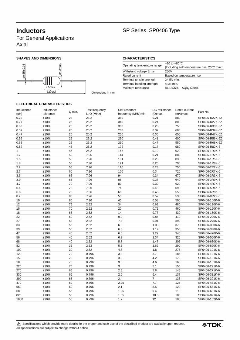
Inductors SP Series SP0406 Type
For General ApplicationsAxial
SHAPES AND DIMENSIONS CHARACTERISTICS
ELECTRICAL CHARACTERISTICS
ø0.
65±0
.05
ø4.
2max
.
Dimensions in mm
9.5max.
62(ref.)
Operating temperature range–20 to +80°C[Including self-temperature rise, 20°C max.]
Withstand voltage Erms 250VRated current Based on temperature riseTerminal tensile strength 24.5N min.Terminal bending strength 4.9N min.Moisture resistance ∆L/L 5% ∆Q/Q 20%
Inductance(µH)
Inductancetolerance
Q min.Test frequencyL, Q (MHz)
Self-resonantfrequency (MHz)min.
DC resistance(Ω)max.
Rated current(mA)max.
Part No.
0.22 ±10% 25 25.2 380 0.21 880 SP0406-R22K-6Z0.27 ±10% 25 25.2 340 0.24 800 SP0406-R27K-6Z0.33 ±10% 25 25.2 300 0.28 750 SP0406-R33K-6Z0.39 ±10% 25 25.2 280 0.32 680 SP0406-R39K-6Z0.47 ±10% 25 25.2 250 0.36 650 SP0406-R47K-6Z0.56 ±10% 25 25.2 230 0.41 600 SP0406-R56K-6Z0.68 ±10% 25 25.2 210 0.47 550 SP0406-R68K-6Z0.82 ±10% 45 25.2 172 0.17 980 SP0406-R82K-61 ±10% 45 25.2 157 0.19 920 SP0406-1R0K-61.2 ±10% 50 7.96 144 0.21 880 SP0406-1R2K-61.5 ±10% 50 7.96 131 0.23 830 SP0406-1R5K-61.8 ±10% 55 7.96 121 0.25 790 SP0406-1R8K-62.2 ±10% 55 7.96 110 0.28 750 SP0406-2R2K-62.7 ±10% 60 7.96 100 0.3 720 SP0406-2R7K-63.3 ±10% 65 7.96 94 0.34 670 SP0406-3R3K-63.9 ±10% 65 7.96 86 0.37 640 SP0406-3R9K-64.7 ±10% 70 7.96 80 0.39 620 SP0406-4R7K-65.6 ±10% 70 7.96 74 0.43 590 SP0406-5R6K-66.8 ±10% 75 7.96 68 0.48 550 SP0406-6R8K-68.2 ±10% 80 7.96 53 0.52 530 SP0406-8R2K-610 ±10% 85 7.96 45 0.58 500 SP0406-100K-612 ±10% 75 2.52 34 0.63 480 SP0406-120K-615 ±10% 70 2.52 20 0.72 460 SP0406-150K-618 ±10% 65 2.52 14 0.77 430 SP0406-180K-622 ±10% 60 2.52 9.9 0.84 410 SP0406-220K-627 ±10% 55 2.52 7.6 0.94 390 SP0406-270K-633 ±10% 55 2.52 6.3 1.03 370 SP0406-330K-639 ±10% 50 2.52 6.3 1.12 350 SP0406-390K-647 ±10% 45 2.52 6.3 1.22 340 SP0406-470K-656 ±10% 40 2.52 6.2 1.34 320 SP0406-560K-668 ±10% 40 2.52 5.7 1.47 305 SP0406-680K-682 ±10% 35 2.52 5.3 1.62 290 SP0406-820K-6100 ±10% 30 2.52 4.8 1.8 275 SP0406-101K-6120 ±10% 70 0.796 3.8 3.7 185 SP0406-121K-6150 ±10% 70 0.796 3.5 4.2 175 SP0406-151K-6180 ±10% 70 0.796 3.3 4.6 165 SP0406-181K-6220 ±10% 70 0.796 3 5.1 155 SP0406-221K-6270 ±10% 65 0.796 2.8 5.8 145 SP0406-271K-6330 ±10% 65 0.796 2.6 6.4 137 SP0406-331K-6390 ±10% 65 0.796 2.4 7 133 SP0406-391K-6470 ±10% 60 0.796 2.25 7.7 126 SP0406-471K-6560 ±10% 60 0.796 2.1 8.5 120 SP0406-561K-6680 ±10% 55 0.796 1.95 9.4 113 SP0406-681K-6820 ±10% 55 0.796 1.85 10.5 100 SP0406-821K-61000 ±10% 50 0.796 1.7 12 100 SP0406-102K-6
Specifications which provide more details for the proper and safe use of the described product are available upon request.All specifications are subject to change without notice.

513_SP0406
Inductors SP Series SP0406 Type
For General ApplicationsAxial
TYPICAL ELECTRICAL CHARACTERISTICSINDUCTANCE CHANGE vs. DC SUPERPOSITIONCHARACTERISTICS
INDUCTANCE CHANGE vs. TEMPERATURECHARACTERISTICS
Q vs. FREQUENCY CHARACTERISTICS
DC current(mA)10
10
5
1
100
1000
500
50
1000
5000
50 100 500 50001000 10000
Indu
ctan
ce( µ
H)
AL=5H C=20000µF
Test circuit
DC
LCR
met
er
Specimen
470mH
1000µH
100µH
22µH
220µH
47µH
4.7µH
10µH
2.2µH
–40 –20 0 20
2
1
–2
–1
40 60 80
∆L
/L( %
)
Temperature(°C)
234
1
1
432
Test frequency1 1.2µH: 6MHz2 1.5µH: 3MHz3 22µH: 3MHz4 1000µH: 0.4MHz
0.1 0.2 1 20.5 10 20 50 1005
Frequency(MHz)
20
40
60
80
100
120
140
Q
1000µH 82µH 22µH47µH
980406
Specifications which provide more details for the proper and safe use of the described product are available upon request.All specifications are subject to change without notice.

Inductors SP Series SP0508 Type
For Power LineAxial
FEATURES• These inductors feature low DC resistance and high current
handling capacities, making them ideal for power supply line
applications.
• These are coaxial horizontal types, highly miniaturized and
lightweight.
• Available in ammo-pack style tape packaging to support
automated mounting machines.
APPLICATIONSTelevisions, VCRs, personal computers, and other electronic
equipment.
SPECIFICATIONS
PRODUCT IDENTIFICATION
(1)Series name (Taping products are standard)
(2)Dimensions
(3)Packaging style
(4)Inductance value
(5)Inductance tolerance
(6)Rated current
(7)TDK internal code
(Some products may not have this number. See the main body
for details).
PACKAGING STYLE AND QUANTITIES
COLOR CODE MARKINGS (from left)1: The first effective number
2: The second effective number
3: Multiplier
SP0508 TYPE
Color code table
• According to JIS-C-0801
Type InductanceOperating temperature range[Including self-temperature rise]
Storage temperature range[Unit of products]
Terminal tensilestrength
SP0508 1 to 4700µH –20 to +85°C –40 to +85°C 24.5N min.
SP BulkSPT Taping
0508 ø4.5×14mm
A Dimensions in between tapes 52mmNo code Bulk
1R0 1µH101 100µH
K ±10%
3R8 3.8AR70 0.7A
0508 A- 1R0 K - 3R8 -X
(2) (3) (4) (5) (6) (7)
SP
SPT
(1)
Packaging style Type QuantityTaping(Ammo-pack)
SPT0508A 1000 pieces/box
Bulk SP0508 200 pieces/pack
Color Effective number Multiplier Inductance toleranceBlack 0 1 ±20%Brown 1 10 —Red 2 100 —Orange 3 1000 —Yellow 4 — —Green 5 — —Blue 6 — —Purple 7 — —Gray 8 — —White 9 — —Silver — 0.01 ±10%Gold — 0.1 ±5%
1Color code
Specifications which provide more details for the proper and safe use of the described product are available upon request.All specifications are subject to change without notice.
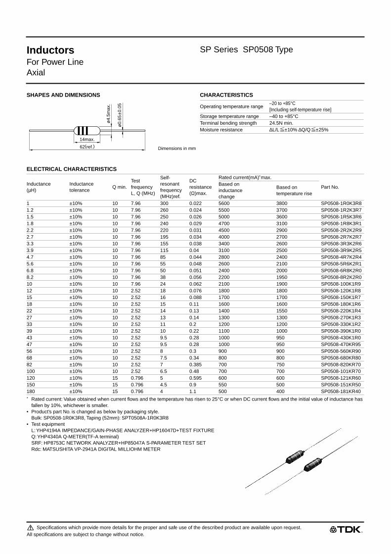
Inductors SP Series SP0508 Type
For Power LineAxial
SHAPES AND DIMENSIONS CHARACTERISTICS
ELECTRICAL CHARACTERISTICS
∗ Rated current: Value obtained when current flows and the temperature has risen to 25°C or when DC current flows and the initial value of inductance has fallen by 10%, whichever is smaller.
• Product’s part No. is changed as below by packaging style.Bulk: SP0508-1R0K3R8, Taping (52mm): SPT0508A-1R0K3R8
• Test equipmentL: YHP4194A IMPEDANCE/GAIN-PHASE ANALYZER+HP16047D+TEST FIXTUREQ: YHP4340A Q-METER(TF-A terminal)SRF: HP8753C NETWORK ANALYZER+HP85047A S-PARAMETER TEST SETRdc: MATSUSHITA VP-2941A DIGITAL MILLIOHM METER
62(ref.)
14max.
ø0.
65±0
.05
ø4.
5max
.
Dimensions in mm
Operating temperature range–20 to +85°C[Including self-temperature rise]
Storage temperature range –40 to +85°CTerminal bending strength 24.5N min.Moisture resistance ∆L/L ±10% ∆Q/Q ±25%
Inductance(µH)
Inductancetolerance
Q min.Test frequencyL, Q (MHz)
Self-resonantfrequency(MHz)ref.
DC resistance(Ω)max.
Rated current(mA)∗ max.
Part No.Based on inductancechange
Based ontemperature rise
1 ±10% 10 7.96 300 0.022 5600 3800 SP0508-1R0K3R81.2 ±10% 10 7.96 260 0.024 5500 3700 SP0508-1R2K3R71.5 ±10% 10 7.96 250 0.026 5000 3600 SP0508-1R5K3R61.8 ±10% 10 7.96 240 0.029 4700 3100 SP0508-1R8K3R12.2 ±10% 10 7.96 220 0.031 4500 2900 SP0508-2R2K2R92.7 ±10% 10 7.96 195 0.034 4000 2700 SP0508-2R7K2R73.3 ±10% 10 7.96 155 0.038 3400 2600 SP0508-3R3K2R63.9 ±10% 10 7.96 115 0.04 3100 2500 SP0508-3R9K2R54.7 ±10% 10 7.96 85 0.044 2800 2400 SP0508-4R7K2R45.6 ±10% 10 7.96 55 0.048 2600 2100 SP0508-5R6K2R16.8 ±10% 10 7.96 50 0.051 2400 2000 SP0508-6R8K2R08.2 ±10% 10 7.96 38 0.056 2200 1950 SP0508-8R2K2R010 ±10% 10 7.96 24 0.062 2100 1900 SP0508-100K1R912 ±10% 10 2.52 18 0.076 1800 1800 SP0508-120K1R815 ±10% 10 2.52 16 0.088 1700 1700 SP0508-150K1R718 ±10% 10 2.52 15 0.11 1600 1600 SP0508-180K1R622 ±10% 10 2.52 14 0.13 1400 1550 SP0508-220K1R427 ±10% 10 2.52 13 0.14 1300 1300 SP0508-270K1R333 ±10% 10 2.52 11 0.2 1200 1200 SP0508-330K1R239 ±10% 10 2.52 10 0.22 1100 1000 SP0508-390K1R043 ±10% 10 2.52 9.5 0.28 1000 950 SP0508-430K1R047 ±10% 10 2.52 9.5 0.28 1000 950 SP0508-470KR9556 ±10% 10 2.52 8 0.3 900 900 SP0508-560KR9068 ±10% 10 2.52 7.5 0.34 800 800 SP0508-680KR8082 ±10% 10 2.52 7 0.385 700 750 SP0508-820KR70100 ±10% 10 2.52 6.5 0.48 700 700 SP0508-101KR70120 ±10% 15 0.796 5 0.595 600 600 SP0508-121KR60150 ±10% 15 0.796 4.5 0.9 550 500 SP0508-151KR50180 ±10% 15 0.796 4 1.1 500 400 SP0508-181KR40
Specifications which provide more details for the proper and safe use of the described product are available upon request.All specifications are subject to change without notice.

513_SP0508
Inductors SP Series SP0508 Type
For Power LineAxial
ELECTRICAL CHARACTERISTICS
∗ Rated current: Value obtained when current flows and the temperature has risen to 25°C or when DC current flows and the initial value of inductance has fallen by 10%, whichever is smaller.
• Product’s part No. is changed as below by packaging style.Bulk: SP0508-1R0K3R8, Taping (52mm): SPT0508A-1R0K3R8
• Test equipmentL: YHP4194A IMPEDANCE/GAIN-PHASE ANALYZER+HP16047D+TEST FIXTUREQ: YHP4340A Q-METER (TF-A terminal)SRF: HP8753C NETWORK ANALYZER+HP85047A S-PARAMETER TEST SETRdc: MATSUSHITA VP-2941A DIGITAL MILLIOHM METER
TYPICAL ELECTRICAL CHARACTERISTICSINDUCTANCE CHANGE vs. DC SUPERPOSITIONCHARACTERISTICS ATTENUATION vs. FREQUENCY CHARACTERISTICS
Inductance(µH)
Inductancetolerance
Q min.Test frequencyL, Q (MHz)
Self-resonantfrequency(MHz)ref.
DC resistance(Ω)max.
Rated current(mA)∗ max.
Part No.Based oninductancechange
Based ontemperature rise
220 ±10% 15 0.796 3.8 1.25 440 390 SP0508-221KR39270 ±10% 15 0.796 3.5 1.85 420 330 SP0508-271KR33330 ±10% 15 0.796 3 2.1 380 310 SP0508-331KR31390 ±10% 15 0.796 2.8 2.28 340 300 SP0508-391KR30470 ±10% 15 0.796 2.5 3.22 320 280 SP0508-471KR28560 ±10% 15 0.796 2.2 3.85 290 270 SP0508-561KR27680 ±10% 15 0.796 2.1 4 260 240 SP0508-681KR24820 ±10% 15 0.796 2 5 250 230 SP0508-821KR231000 ±10% 15 0.796 1.8 5.8 240 190 SP0508-102KR191200 ±10% 15 0.252 1.6 7.1 200 180 SP0508-122KR181500 ±10% 15 0.252 1.5 7.8 190 170 SP0508-152KR174700 ±10% 50 0.252 0.7 30 120 100 SP0508-472KR10
DC current(A)0.01
1
0.3
0
10
100
30
3
1000
300
0.1 0.30.03 31 10
Indu
ctan
ce( µ
H)
100µH
10µH
1µH
AL=0.1H C=20000µF
Test circuit
YHP model-4263Aor equivalent
DC
Uni
vers
al b
ridge
Specimen
1000µH
–100
–90
–80
–70
–60
–50
–40
–20
–30
Frequency(MHz)0.3
–10
0
1 3 30 10010 300 1000
Atte
nuat
ion
( dB
) 1µH
10µH
100µH
1000µH
980601
Specifications which provide more details for the proper and safe use of the described product are available upon request.All specifications are subject to change without notice.
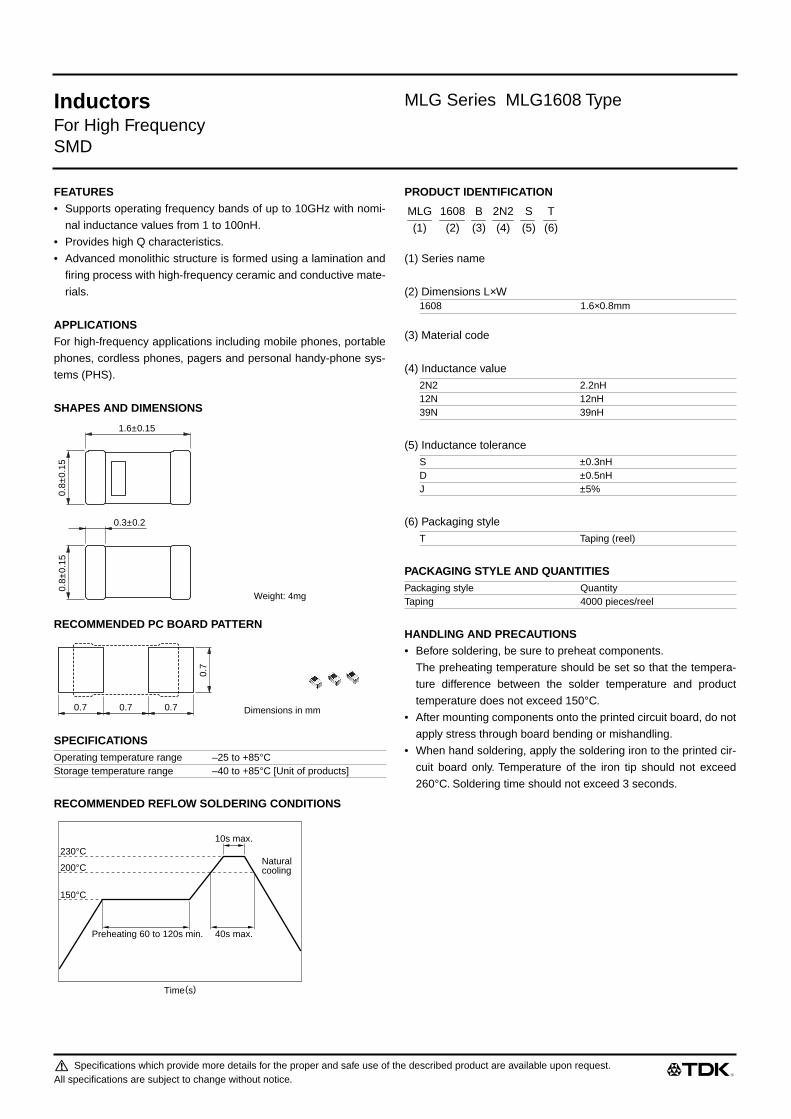
Inductors MLG Series MLG1608 Type
For High FrequencySMD
FEATURES• Supports operating frequency bands of up to 10GHz with nomi-
nal inductance values from 1 to 100nH.
• Provides high Q characteristics.
• Advanced monolithic structure is formed using a lamination and
firing process with high-frequency ceramic and conductive mate-
rials.
APPLICATIONSFor high-frequency applications including mobile phones, portable
phones, cordless phones, pagers and personal handy-phone sys-
tems (PHS).
SHAPES AND DIMENSIONS
RECOMMENDED PC BOARD PATTERN
SPECIFICATIONS
RECOMMENDED REFLOW SOLDERING CONDITIONS
PRODUCT IDENTIFICATION
(1) Series name
(2) Dimensions L×W
(3) Material code
(4) Inductance value
(5) Inductance tolerance
(6) Packaging style
PACKAGING STYLE AND QUANTITIES
HANDLING AND PRECAUTIONS• Before soldering, be sure to preheat components.
The preheating temperature should be set so that the tempera-
ture difference between the solder temperature and product
temperature does not exceed 150°C.
• After mounting components onto the printed circuit board, do not
apply stress through board bending or mishandling.
• When hand soldering, apply the soldering iron to the printed cir-
cuit board only. Temperature of the iron tip should not exceed
260°C. Soldering time should not exceed 3 seconds.
Operating temperature range –25 to +85°CStorage temperature range –40 to +85°C [Unit of products]
1.6±0.15
0.3±0.2
0.8±
0.15
0.8±
0.15
Weight: 4mg
0.7
0.7 0.7 0.7 Dimensions in mm
10s max.
40s max.Preheating 60 to 120s min.
Naturalcooling
230°C
200°C
150°C
Time(s)
1608 1.6×0.8mm
2N2 2.2nH12N 12nH39N 39nH
S ±0.3nHD ±0.5nHJ ±5%
T Taping (reel)
Packaging style QuantityTaping 4000 pieces/reel
MLG 1608 B 2N2 S T
(1) (2) (3) (4) (5) (6)
Specifications which provide more details for the proper and safe use of the described product are available upon request.All specifications are subject to change without notice.

521_MLG1608
Inductors MLG Series MLG1608 Type
For High FrequencySMD
ELECTRICAL CHARACTERISTICS
• Test equipment Inductance Q : HP4291A+16193A SRF: HP8720C Rdc: YOKOGAWA TYPE7561• Rated current : Value obtained when current flows and temperature has risen to 20°C.
TYPICAL ELECTRICAL CHARACTERISTICSINDUCTANCE vs. FREQUENCY IMPEDANCE vs. FREQUENCY Q vs. FREQUENCY CHARACTERISTICSCHARACTERISTICS CHARACTERISTICS
Inductance(nH)
Inductancetolerance
Qmin.
Test frequencyL, Q (MHz)
Self-resonantfrequency (GHz)min.
DC resistance(Ω)max.
Rated current(mA)max.
Part No.
1 ±0.3nH 8 100 10 0.1 300 MLG1608B1N0S1.2 ±0.3nH 8 100 10 0.1 300 MLG1608B1N2S1.5 ±0.3nH 8 100 10 0.1 300 MLG1608B1N5S1.8 ±0.3nH 8 100 9.8 0.1 300 MLG1608B1N8S2.2 ±0.3nH 10 100 7.6 0.15 300 MLG1608B2N2S2.7 ±0.3nH 10 100 7 0.15 300 MLG1608B2N7S3.3 ±0.3nH 10 100 6.2 0.2 300 MLG1608B3N3S3.9 ±0.3nH 10 100 5.6 0.2 300 MLG1608B3N9S4.7 ±0.3nH 10 100 4.8 0.2 300 MLG1608B4N7S5.6 ±0.5nH 10 100 4.6 0.2 300 MLG1608B5N6D6.8 ±0.5nH 10 100 4.2 0.2 300 MLG1608B6N8D8.2 ±0.5nH 10 100 3.6 0.25 300 MLG1608B8N2D10 ±5% 12 100 3.2 0.25 300 MLG1608B10NJ12 ±5% 12 100 2.8 0.3 300 MLG1608B12NJ15 ±5% 12 100 2.6 0.35 300 MLG1608B15NJ18 ±5% 12 100 2.4 0.4 300 MLG1608B18NJ22 ±5% 12 100 2 0.5 300 MLG1608B22NJ27 ±5% 12 100 1.9 0.55 300 MLG1608B27NJ33 ±5% 12 100 1.6 0.6 300 MLG1608B33NJ39 ±5% 12 100 1.4 0.65 300 MLG1608B39NJ47 ±5% 14 100 1.2 0.7 300 MLG1608B47NJ56 ±5% 14 100 1 0.75 300 MLG1608B56NJ68 ±5% 14 100 0.9 0.8 300 MLG1608B68NJ82 ±5% 14 100 0.8 0.9 300 MLG1608B82NJ100 ±5% 14 100 0.7 1 300 MLG1608BR10J
0.01 0.03 0.1 0.3 1 3 101
3
10
30
100
300
1000
Indu
ctan
ce( n
H)
Frequency(GHz)
39nH
10nH
4.7nH
0.01 0.03 0.1 0.3 1 3 100.1
0.3
1
3
10
30
100
Impe
danc
e( k
Ω)
Frequency(GHz)
39nH
10nH4.7nH
0.1 0.3 1 3 100
10
20
30
40
50
60
80
70
Q
Frequency(GHz)
4.7nH10nH
39nH
981007
Specifications which provide more details for the proper and safe use of the described product are available upon request.All specifications are subject to change without notice.

521_MLK1005
(1/2)
Inductors MLK Series MLK1005 Type
For High FrequencySMD
FEATURES• Supports operating frequency bands of up to 12GHz with nomi-
nal inductance values from 1 to 100nH.
• Provides high Q characteristics.
• Advanced monolithic structure is formed using a lamination and
firing process with high-frequency ceramic and conductive mate-
rials.
• Because the part is non-polarized, it can be used in bulk cas-
sette loaders.
APPLICATIONSHigh-frequency circuits for portable telephones, personal handy-
phone systems(PHS), pagers, or other mobile communication
appliances.
SHAPES AND DIMENSIONS
RECOMMENDED PC BOARD PATTERN
RECOMMENDED REFLOW SOLDERING CONDITIONS
PRODUCT IDENTIFICATION
(1) Series name
(2) Dimensions L×W
(3) Material code
(4) Inductance value
(5) Inductance tolerance
(6) Packaging style
PACKAGING STYLE AND QUANTITIES
SPECIFICATIONS
HANDLING AND PRECAUTIONS• Before soldering, be sure to preheat components.
The preheating temperature should be set so that the tempera-
ture difference between the solder temperature and product
temperature does not exceed 150°C.
• After mounting components onto the printed circuit board, do not
apply stress through board bending or mishandling.
• When hand soldering, apply the soldering iron to the printed cir-
cuit board only. Temperature of the iron tip should not exceed
260°C. Soldering time should not exceed 3 seconds.
1±0.1
0.1min.
0.5
±0.1
0.5
±0.1
Weight: 1.0mg
0.5
0.5 0.4 0.5 Dimensions in mm
10s max.
40s max.
60 to 120s max.
Naturalcooling
200°C
150°C
230°C
Time(s)
1005 1.0×0.5mm
2N2 2.2nH12N 12nH
S ±0.3nHD ±0.5nHJ ±5%
T Taping (reel)
Packaging style QuantityTaping 10000 pieces/reel
Operating temperature range –25 to +85°CStorage temperature range –40 to +85°C [Unit of product]
MLK 1005 S 2N2 S X
(1) (2) (3) (4) (5) (6)
Specifications which provide more details for the proper and safe use of the described product are available upon request.All specifications are subject to change without notice.

521_MLK1005
(2/2)
521_MLK1005
Inductors MLK Series MLK1005 Type
For High FrequencySMD
ELECTRICAL CHARACTERISTICS
• Test equipmentInductance Q: HP4291A+16193A SRF: HP8720C Rdc:YOKOGAWA TYPE7561
• Rated current: Value obtained when current flows and temperature has risen to 20°C
TYPICAL ELECTRICAL CHARACTERISTICSINDUCTANCE vs. FREQUENCY CHARACTERISTICS Q vs. FREQUENCY CHARACTERISTICS
Inductance(nH)
Inductancetolerance
Qmin.
Qtyp.
Self-resonantfrequency(GHz)
DC resistance(Ω)
Ratedcurrent(mA)max.
Part No.100MHz 100MHz 300MHz 500MHz 1000MHz min. typ. max. typ.
1 ±0.3nH 5 7 12 15 24 12 19 0.1 0.05 300 MLK1005S1N0S1.2 ±0.3nH 5 7 13 17 26 11 16.2 0.15 0.07 300 MLK1005S1N2S1.5 ±0.3nH 6 8 15 19 28 9.5 13.6 0.16 0.08 300 MLK1005S1N5S1.8 ±0.3nH 6 8 15 19 29 8.5 10.5 0.2 0.11 300 MLK1005S1N8S2.2 ±0.3nH 6 8 15 20 29 8 10 0.21 0.11 300 MLK1005S2N2S2.7 ±0.3nH 6 8 15 20 30 7.5 9.2 0.23 0.16 300 MLK1005S2N7S3.3 ±0.3nH 7 9 16 21 32 7 8.5 0.25 0.16 300 MLK1005S3N3S3.9 ±0.3nH 7 9 16 21 30 6.5 8.2 0.28 0.16 300 MLK1005S3N9S4.7 ±0.3nH 7 9 16 21 31 6 7.3 0.32 0.19 300 MLK1005S4N7S5.6 ±0.5nH 7 9 16 21 31 5.7 7.2 0.35 0.21 300 MLK1005S5N6D6.8 ±0.5nH 7 9 16 21 31 5.5 6.8 0.38 0.28 300 MLK1005S6N8D8.2 ±0.5nH 7 9 16 21 31 5 6.5 0.42 0.31 300 MLK1005S8N2D10 ±5% 7 9 16 21 31 4.7 6.3 0.45 0.33 200 MLK1005S10NJ12 ±5% 7 9 16 21 32 4.3 6.2 0.5 0.41 200 MLK1005S12NJ15 ±5% 7 9 16 21 30 4 5.6 0.55 0.44 200 MLK1005S15NJ18 ±5% 7 9 16 21 30 3.7 5.3 0.65 0.53 200 MLK1005S18NJ22 ±5% 7 9 16 21 30 3.5 5.1 0.75 0.58 200 MLK1005S22NJ27 ±5% 7 9 16 20 28 3 4.7 0.95 0.75 200 MLK1005S27NJ33 ±5% 7 9 16 20 27 2.5 4.2 1.1 0.81 200 MLK1005S33NJ39 ±5% 6 9 16 20 27 2 3.4 1.2 0.67 100 MLK1005S39NJ47 ±5% 6 9 16 20 26 1.8 2.9 1.3 0.79 100 MLK1005S47NJ56 ±5% 6 9 16 20 25 1.5 2.8 1.4 0.97 100 MLK1005S56NJ68 ±5% 6 9 15 19 23 1.2 2.7 1.6 1.18 100 MLK1005S68NJ82 ±5% 6 9 14 18 20 1 2.1 1.8 1.24 50 MLK1005S82NJ100 ±5% 6 9 14 17 20 0.8 2 2.2 1.5 50 MLK1005SR10J
10 30 100 300 1000 3000 100001
3
10
30
100
33nH
22nH10nH
4.7nH
2.2nH
1.2nH
Indu
ctan
ce( n
H)
Frequency(MHz)3010 100 1000300 3000 10000
0
10
20
30
40
50
Q
Frequency(MHz)
18nH
1.2nH33nH
1nH
010301
Specifications which provide more details for the proper and safe use of the described product are available upon request.All specifications are subject to change without notice.
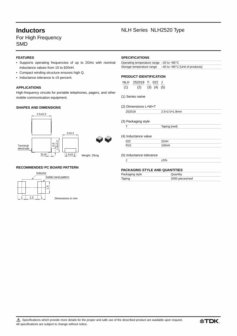
Inductors NLH Series NLH2520 Type
For High FrequencySMD
FEATURES• Supports operating frequencies of up to 2GHz with nominal
inductance values from 10 to 820nH.
• Compact winding structure ensures high Q.
• Inductance tolerance is ±5 percent.
APPLICATIONSHigh-frequency circuits for portable telephones, pagers, and other
mobile communication equipment.
SHAPES AND DIMENSIONS
RECOMMENDED PC BOARD PATTERN
SPECIFICATIONS
PRODUCT IDENTIFICATION
(1) Series name
(2) Dimensions L×W×T
(3) Packaging style
(4) Inductance value
(5) Inductance tolerance
PACKAGING STYLE AND QUANTITIES
2.5±0.2
2±0.2
1.8
±0.2
0.5
(0.4)
Terminalelectrode
1.4±0.1 Weight: 25mg
1.5
Solder land patternInductor
11.51 Dimensions in mm
Operating temperature range –20 to +85°CStorage temperature range –40 to +85°C [Unit of products]
252018 2.5×2.0×1.8mm
T Taping [reel]
022 22nHR10 100nH
J ±5%
Packaging style QuantityTaping 2000 pieces/reel
NLH 252018 T- 022 J
(1) (2) (3) (4) (5)
Specifications which provide more details for the proper and safe use of the described product are available upon request.All specifications are subject to change without notice.

521_NLH2520
Inductors NLH Series NLH2520 Type
For High FrequencySMD
ELECTRICAL CHARACTERISTICS
• Test equipmentInductance, Q[10 to 100nH] : YHP4291A IMPEDANCE/MATERIAL ANALYZER+YHP16191A, or equivalentInductance Q[120 to 820nH] : YHP4194A IMPEDANCE ANALYZER+YHP16085A+YHP16093B+TF-1, or equivalentSRF: HP8753C NETWORK ANALYZER(Zin, Zout=50Ω), or equivalentRdc : MATSUSHITA VP-2941A DIGITAL MILLIOHM METER, or equivalent
TYPICAL ELECTRICAL CHARACTERISTICSINDUCTANCE vs. FREQUENCY CHARACTERISTICS Q vs. FREQUENCY CHARACTERISTICS
Inductance(nH)
Inductancetolerance
Qmin.
Test frequencyL, Q (MHz)
Self-resonantfrequency (GHz)min.
DC resistance(Ω)max.
Rated current(mA)max.
Part No.
10 ±5% 25 100 2.15 0.26 530 NLH252018T-010J12 ±5% 25 100 2.05 0.27 500 NLH252018T-012J15 ±5% 25 100 2 0.29 480 NLH252018T-015J18 ±5% 25 100 1.85 0.31 450 NLH252018T-018J22 ±5% 25 100 1.65 0.37 420 NLH252018T-022J27 ±5% 25 100 1.55 0.4 410 NLH252018T-027J33 ±5% 25 100 1.45 0.42 400 NLH252018T-033J39 ±5% 25 100 1.35 0.45 380 NLH252018T-039J47 ±5% 25 100 1.2 0.5 360 NLH252018T-047J56 ±5% 25 100 1.1 0.6 340 NLH252018T-056J68 ±5% 25 100 1.05 0.65 320 NLH252018T-068J82 ±5% 25 100 0.9 0.75 300 NLH252018T-082J100 ±5% 25 100 0.8 0.8 280 NLH252018T-R10J120 ±5% 30 25.2 0.7 0.38 550 NLH252018T-R12J150 ±5% 30 25.2 0.55 0.42 500 NLH252018T-R15J180 ±5% 30 25.2 0.5 0.45 475 NLH252018T-R18J220 ±5% 35 25.2 0.45 0.5 450 NLH252018T-R22J270 ±5% 35 25.2 0.425 0.58 425 NLH252018T-R27J330 ±5% 40 25.2 0.4 0.68 400 NLH252018T-R33J390 ±5% 40 25.2 0.375 0.73 375 NLH252018T-R39J470 ±5% 40 25.2 0.35 0.83 350 NLH252018T-R47J560 ±5% 40 25.2 0.325 0.93 325 NLH252018T-R56J680 ±5% 40 25.2 0.18 0.98 300 NLH252018T-R68J820 ±5% 40 25.2 0.12 1.05 260 NLH252018T-R82J
10 30 100 300 1000 3000 100001
3
10
30
100
300
1000
Indu
ctan
ce( n
H)
Frequency(MHz)
47nH
100nH
22nH
10nH
YHP4291A IMPEDANCE/MATERIAL ANALYZER+YHP16191A
10 30 100 300 1000 3000 10000Frequency(MHz)
Q
0
20
40
60
80
100
120
10nH
22nH
100nH
47nH
YHP4291A IMPEDANCE/MATERIAL ANALYZER+YHP16191A
980420
Specifications which provide more details for the proper and safe use of the described product are available upon request.All specifications are subject to change without notice.

Specifications which provide more details for the proper and safe use of the described product are available upon request.All specifications are subject to change without notice.
521_NLU1608
(1/2)
Inductors
NLU Series NLU1608 Type
For High FrequencySMD
FEATURES
• Q has been increased by forming the special spiral-form con-
ductor mainly composed of copper on the thin-film multilayer
structure and reducing direct current resistance.
• Narrow inductance tolerance of ±2% or ±0.2nH has been
achieved by increasing the dimensional precision of the conduc-
tor and between them.
• Accurate dimensional precision has been achieved as well as
excellent soldering heat resistance.
• Concurrent use with ultra-small chip components is possible due
to the thickness of 0.6mm.
• Compatible with either reflow or flow soldering
APPLICATIONS
High-frequency circuits for portable telephones, pagers, or other
mobile communication appliances.
SPECIFICATIONS
RECOMMENDED REFLOW SOLDERING CONDITIONS
PRODUCT IDENTIFICATION
(1)Series name
(2)Dimensions L
×
W
×
T
(3)Packaging style
(4)Inductance value
(5)Inductance tolerance
PACKAGING STYLE AND QUANTITIES
Operating temperature range –40 to +100°CStorage temperature range –55 to +125°C [Unit of products]
10s max.
30s max.
Preheating: 120s
100°C
200°C
230°C
150°C
Time(s)
Naturalcooling
160805 1.6
×
0.8
×
0.58mm201205 2.0
×
1.2
×
0.58mm
T Taping (reel)
2N2 2.2nH12N 12nHR10 100nH
C ±0.2nHG ±2%
Packaging style QuantityTaping 4000 pieces/reel
NLU 160805 T - 2N2 C
(1) (2) (3) (4) (5)

521_NLU1608991101
Specifications which provide more details for the proper and safe use of the described product are available upon request.All specifications are subject to change without notice.
521_NLU1608
(2/2)
Inductors
NLU Series NLU1608 Type
For High FrequencySMD
SHAPES AND DIMENSIONS/RECOMMENDED PC BOARD PATTERN
ELECTRICAL CHARACTERISTICS
• L, Q : HP4291A IMPEDANCE ANALYZER+16193A TEST FIXTURESRF : HP8753C NETWORK ANALYZER Typical value : HP8719C NETWORK ANALYZERRdc : MATSUSHITA DIGITAL MILLIOHM METER VP-2941A or equivalent
TYPICAL ELECTRICAL CHARACTERISTICSQ vs. FREQUENCY CHARACTERISTICS INDUCTANCE vs. FREQUENCY CHARACTERISTICS
Inductance(nH)
Inductancetolerance
QTest frequency L, Q(MHz)
Self-resonantfrequency (GHz)
DCresistance(
Ω
)max.
Ratedcurrent(mA)max.
Part No.min. typ. min. typ.
1.2 ±0.2nH 13 20 300 5 12.5 0.08 400 NLU160805T-1N2C1.5 ±0.2nH 13 18 300 5 11.5 0.1 400 NLU160805T-1N5C1.8 ±0.2nH 13 19 300 5 10.5 0.11 400 NLU160805T-1N8C2.2 ±0.2nH 13 20 300 5 9.5 0.12 400 NLU160805T-2N2C2.7 ±0.2nH 13 19 300 5 8.4 0.14 400 NLU160805T-2N7C3.3 ±0.2nH 13 19 300 5 7.6 0.16 320 NLU160805T-3N3C3.9 ±0.2nH 13 19 300 5 6.8 0.18 320 NLU160805T-3N9C4.7 ±0.2nH 13 19 300 5 6.5 0.28 240 NLU160805T-4N7C5.6 ±0.2nH 13 21 300 4.6 5.8 0.31 240 NLU160805T-5N6C6.8 ±0.2nH 13 19 300 4.1 5.1 0.37 240 NLU160805T-6N8C8.2 ±0.2nH 13 19 300 3.9 4.9 0.55 170 NLU160805T-8N2C10 ±2% 13 20 300 3.5 4.4 0.64 170 NLU160805T-10NG12 ±2% 13 18 300 3.1 3.9 0.7 170 NLU160805T-12NG15 ±2% 13 20 300 2.8 3.5 0.95 130 NLU160805T-15NG18 ±2% 13 20 300 2.5 3.1 1.2 130 NLU160805T-18NG22 ±2% 13 19 300 2.3 2.9 1.9 100 NLU160805T-22NG27 ±2% 13 20 300 2 2.6 2.1 100 NLU160805T-27NG33 ±2% 13 19 300 1.9 2.4 3.2 80 NLU160805T-33NG39 ±2% 13 18 300 1.7 2.2 4.4 70 NLU160805T-39NG47 ±2% 12 17 300 1.5 2 6.2 60 NLU160805T-47NG
Weight: 3mg
Dimensions in mm
(0.23)
0.58
±0.0
5
Heat resistanceresin coating
Thin-filmedspiral coil
Ceramicsubstrate
Terminalelectrode
1.62±0.05
0.85
±0.0
5
0.65
0.6
0.90.652.2
(0.23)
0.1 0.3 1 3 10 30 100Frequency(GHz)
Q
100
30
10
1
3
3.9nH
18nH
10nH
27nH
0.1 0.3 1 3 10 30 100Frequency(GHz)
Indu
ctan
ce( n
H)
100
30
10
1
3
10nH
18nH
27nH
3.9nH

Specifications which provide more details for the proper and safe use of the described product are available upon request.All specifications are subject to change without notice.
521_NLU2012
(1/2)
Inductors
NLU Series NLU2012 Type
For High FrequencySMD
FEATURES
• Q has been increased by forming the special spiral-form con-
ductor mainly composed of copper on the thin-film multilayer
structure and reducing direct current resistance.
• Narrow inductance tolerance of ±2% or ±0.2nH has been
achieved by increasing the dimensional precision of the conduc-
tor and between them.
• Accurate dimensional precision has been achieved as well as
excellent soldering heat resistance.
• Concurrent use with ultra-small chip components is possible due
to the thickness of 0.6mm.
• Compatible with either reflow or flow soldering
APPLICATIONS
High-frequency circuits for portable telephones, pagers, or other
mobile communication appliances.
SPECIFICATIONS
RECOMMENDED REFLOW SOLDERING CONDITIONS
PRODUCT IDENTIFICATION
(1)Series name
(2)Dimensions L
×
W
×
T
(3)Packaging style
(4)Inductance value
(5)Inductance tolerance
PACKAGING STYLE AND QUANTITIES
Operating temperature range –40 to +100°CStorage temperature range –55 to +125°C [Unit of products]
10s max.
30s max.
Preheating: 120s
100°C
200°C
230°C
150°C
Time(s)
Naturalcooling
160805 1.6
×
0.8
×
0.58mm201205 2.0
×
1.2
×
0.58mm
T Taping (reel)
2N2 2.2nH12N 12nHR10 100nH
C ±0.2nHG ±2%
Packaging style QuantityTaping 4000 pieces/reel
NLU 160805 T - 2N2 C
(1) (2) (3) (4) (5)

521_NLU2012991101
Specifications which provide more details for the proper and safe use of the described product are available upon request.All specifications are subject to change without notice.
521_NLU2012
(2/2)
Inductors
NLU Series NLU2012 Type
For High FrequencySMD
SHAPES AND DIMENSIONS/RECOMMENDED PC BOARD PATTERN
ELECTRICAL CHARACTERISTICS
• L, Q : HP4291A IMPEDANCE ANALYZER+16193A TEST FIXTURESRF : HP8753C NETWORK ANALYZER Typical value : HP8719C NETWORK ANALYZERRdc : MATSUSHITA DIGITAL MILLIOHM METER VP-2941A or equivalent
TYPICAL ELECTRICAL CHARACTERISTICSQ vs. FREQUENCY CHARACTERISTICS INDUCTANCE vs. FREQUENCY CHARACTERISTICS
Inductance(nH)
Inductancetolerance
QTest frequency L, Q(MHz)
Self-resonantfrequency (GHz)
DC resistance(
Ω
)max.
Ratedcurrent(mA)max.
Part No.min. typ. min. typ.
1.2 ±0.2nH 13 16 300 5 12.3 0.1 500 NLU201205T-1N2C1.5 ±0.2nH 17 22 300 5 10.9 0.1 500 NLU201205T-1N5C1.8 ±0.2nH 19 26 300 5 10.2 0.1 500 NLU201205T-1N8C2.2 ±0.2nH 19 28 300 5 8.5 0.11 500 NLU201205T-2N2C2.7 ±0.2nH 19 27 300 5 8.3 0.13 500 NLU201205T-2N7C3.3 ±0.2nH 19 27 300 5 7.2 0.14 500 NLU201205T-3N3C3.9 ±0.2nH 19 24 300 5 6.4 0.15 500 NLU201205T-3N9C4.7 ±0.2nH 19 24 300 4.4 5.6 0.16 500 NLU201205T-4N7C5.6 ±0.2nH 19 25 300 4.4 5.5 0.23 500 NLU201205T-5N6C6.8 ±0.2nH 19 25 300 3.8 4.8 0.25 500 NLU201205T-6N8C8.2 ±0.2nH 19 29 300 3.3 4.2 0.28 500 NLU201205T-8N2C10 ±2% 19 25 300 3 3.8 0.31 500 NLU201205T-10NG12 ±2% 19 28 300 2.8 3.6 0.47 500 NLU201205T-12NG15 ±2% 19 27 300 2.4 3.1 0.53 360 NLU201205T-15NG18 ±2% 19 28 300 2.3 2.9 0.71 260 NLU201205T-18NG22 ±2% 19 29 300 2 2.6 0.78 250 NLU201205T-22NG27 ±2% 19 28 300 1.8 2.3 0.97 250 NLU201205T-27NG33 ±2% 19 28 300 1.6 2 1.2 210 NLU201205T-33NG39 ±2% 19 26 300 1.4 1.8 1.4 180 NLU201205T-39NG47 ±2% 19 28 300 1.3 1.7 1.8 150 NLU201205T-47NG56 ±2% 19 27 300 1.2 1.6 1.9 150 NLU201205T-56NG68 ±2% 9 14 100 1 1.4 3.3 140 NLU201205T-68NG82 ±2% 9 14 100 0.9 1.3 4.2 120 NLU201205T-82NG100 ±2% 9 14 100 0.8 1.1 5.9 100 NLU201205T-R10G
Weight: 5mg
Dimensions in mm
(0.28)
0.58
±0.0
5
Heat resistanceresin coating
Thin-filmedspiral coil
Ceramicsubstrate
Terminalelectrode
(0.28)
2.02±0.05
1.25
±0.0
5
0.71.20.7
2.6
1
0.01 0.03 0.1 0.3 1 3 10Frequency(GHz)
Q
100
300
30
10
1
3
56nH22nH10nH
2.2nH4.7nH
0.01 0.03 0.1 0.3 1 3 10Frequency(GHz)
Indu
ctan
ce( n
H)
100
300
30
10
1
3
56nH
22nH
10nH
2.2nH
4.7nH
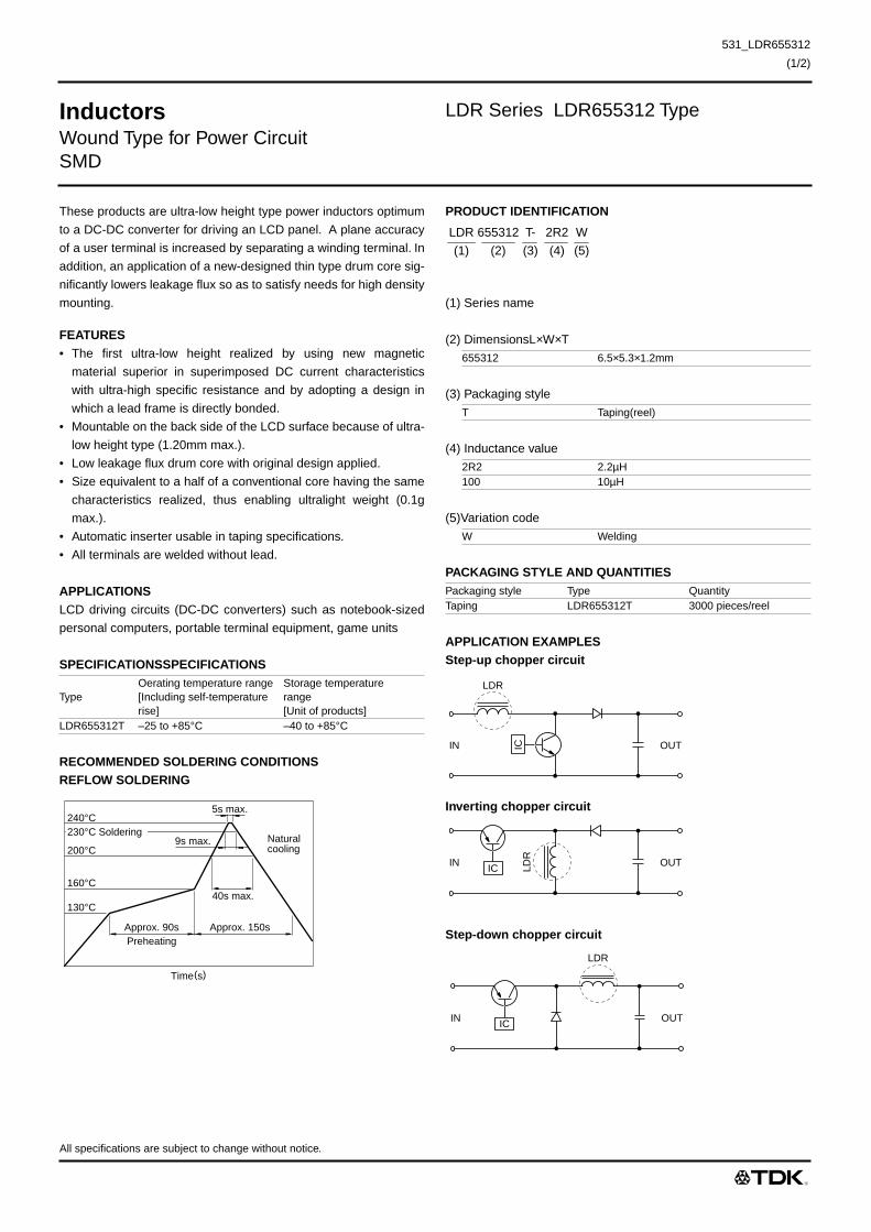
All specifications are subject to change without notice.
531_LDR655312
(1/2)
Inductors
LDR Series LDR655312 Type
Wound Type for Power CircuitSMD
These products are ultra-low height type power inductors optimum
to a DC-DC converter for driving an LCD panel. A plane accuracy
of a user terminal is increased by separating a winding terminal. In
addition, an application of a new-designed thin type drum core sig-
nificantly lowers leakage flux so as to satisfy needs for high density
mounting.
FEATURES
• The first ultra-low height realized by using new magnetic
material superior in superimposed DC current characteristics
with ultra-high specific resistance and by adopting a design in
which a lead frame is directly bonded.
• Mountable on the back side of the LCD surface because of ultra-
low height type (1.20mm max.).
• Low leakage flux drum core with original design applied.
• Size equivalent to a half of a conventional core having the same
characteristics realized, thus enabling ultralight weight (0.1g
max.).
• Automatic inserter usable in taping specifications.
• All terminals are welded without lead.
APPLICATIONS
LCD driving circuits (DC-DC converters) such as notebook-sized
personal computers, portable terminal equipment, game units
SPECIFICATIONSSPECIFICATIONS
RECOMMENDED SOLDERING CONDITIONSREFLOW SOLDERING
PRODUCT IDENTIFICATION
(1) Series name
(2) DimensionsL
×
W
×
T
(3) Packaging style
(4) Inductance value
(5)Variation code
PACKAGING STYLE AND QUANTITIES
APPLICATION EXAMPLESStep-up chopper circuit
Inverting chopper circuit
Step-down chopper circuit
TypeOerating temperature range[Including self-temperature rise]
Storage temperature range[Unit of products]
LDR655312T –25 to +85°C –40 to +85°C
Approx. 90sPreheating
40s max.
Approx. 150s
240°C
200°C
160°C
130°C
9s max.
5s max.
Naturalcooling
Time(s)
230°C Soldering
655312 6.5
×
5.3
×
1.2mm
T Taping(reel)
2R2 2.2
µ
H100 10
µ
H
W Welding
Packaging style Type QuantityTaping LDR655312T 3000 pieces/reel
LDR 655312 T- 2R2 W
(1) (2) (3) (4) (5)
LDR
OUTIN IC
IC LDR
OUTIN
LDR
OUTIN IC

531_LDR655312010306
All specifications are subject to change without notice.
531_LDR655312
(2/2)
Inductors
LDR Series LDR655312 Type
Wound Type for Power CircuitSMD
SHAPES AND DIMENSIONS/RECOMMENDED PC BOARD PATTERN
ELECTRICAL CHARACTERISTICS
∗
Rated current: Value obtained when self-temperature has risen to 40°C.• Test equipment Inductance: YHP 4284 LDR METER, or equivalent(Test frequency:100kHz/20mV)
Rdc:DIGITAL MILLIOHM METER VP-2941A MATSUSHITA, or equivalent
TYPICAL ELECTRICAL CHARACTERISTICSINDUCTANCE CHANGE vs. DC SUPERPOSITIONCHARACTERISTICS
Inductance(mH)
Inductancetolerance (%)
Test frequency L(kHz)
DC resistance(
Ω
)±20%Rated current (A)
∗
max. Part No.
2.2 ±20 100 0.125 1.2 LDR655312T-2R2W3.3 ±20 100 0.155 0.96 LDR655312T-3R3W4.7 ±20 100 0.206 0.9 LDR655312T-4R7W6.8 ±20 100 0.24 0.8 LDR655312T-6R8W10 ±20 100 0.37 0.7 LDR655312T-100W15 ±20 100 0.46 0.6 LDR655312T-150W22 ±20 100 0.668 0.5 LDR655312T-220W33 ±20 100 1.1 0.42 LDR655312T-330W47 ±20 100 1.38 0.34 LDR655312T-470W
6.5max.
Start mark
Marking(Inductance code)
1.2max.
5.3
±0.1
Weight: 0.1g typ.Dimensions in mm
Rising of welded terminal in pack portion
0.08
min
.
22Welding part
#1
#2 #1 #2N1
CONNECTION
#1
#2
64
2.3
1
1
Dimensions in mm
Connection padTerminal reinforcement pad
47µH
33µH
22µH
15µH
10µH
6.8µH
4.7µH
3.3µH
2.2µH
10.01 0.03 0.10.1 0.3 1 3 10
3
10
30
100
Indu
ctan
ce( µ
H)
DC current(A)

Specifications which provide more details for the proper and safe use of the described product are available upon request.All specifications are subject to change without notice.
531_NLC2520
(1/2)
Inductors
NLC Series NLC2520 Type
For Power LineSMD
FEATURES
• The NLC series feature low DC resistance and high current
handling capacities, making them ideal for power supply line
applications.
• They are available in 4 form factors ranging from 2520 to 5650.
APPLICATIONS
Portable telephones, personal computers, hard disk drives, and
other electronic equipment.
SPECIFICATIONS
RECOMMENDED SOLDERING CONDITIONSREFLOW SOLDERING
FLOW SOLDERING
IRON SOLDERING
Perform soldering at 250°C on 30W max. within 5 seconds.
VAPOR-PHASING
FLUX AND CLEANING
Rosin-based flux is recommended.
Cleaning Conditions
PRODUCT IDENTIFICATION
(1) Series name
(2) Dimensions L
×
W
×
T
(3) Packaging style
(4) Inductance value
(5) Inductance tolerance
PACKAGING STYLE AND QUANTITIES
Operating temperature range –20 to +85°CStorage temperature range –40 to +85°C [Unit of products]
30s max.
Preheating: 120s
10s max.
100°C
200°C230°C
150°C
Naturalcooling
Time(s)
Preheating: 120s
10s max.
100°C
260°C
150°C
Naturalcooling
Time(s)
Preheating: 120s
10s max.
100°C
215°C
220°C
150°C
Naturalcooling
30s max.
Time(s)
Solvent Chlorine-based solvent(Do not use acid or alkali solvents.)
Time 2min max.
252018 2.5
×
2.0
×
1.8mm322522 3.2
×
2.5
×
2.2mm453232 4.5
×
3.2
×
3.2mm565050 5.6
×
5.0
×
5.0mm
T Taping(reel)
1R0 1
µ
H330 33
µ
H
K ±10%M ±20%
Packaging style Type QuantityTaping NLC252018T 2000 pieces/reel
NLC322522T 2000 pieces/reelNLC453232T 500 pieces/reelNLC565050T 400 pieces/reel
NLC 252018 T- 2R2 M
(1) (2) (3) (4) (5)

531_NLC2520010405
Specifications which provide more details for the proper and safe use of the described product are available upon request.All specifications are subject to change without notice.
531_NLC2520
(2/2)
Inductors
NLC Series NLC2520 Type
For Power LineSMD
SHAPES AND DIMENSIONS/RECOMMENDED PC BOARD PATTERN
ELECTRICAL CHARACTERISTICS
• Test equipment L, Q: YHP4194A IMPEDANCE ANALYZER+YHP16085A+YHP16093B+TF-1, or equivalentSRF: HP8753C NETWORK ANALYZER (Zin=Zout=50
Ω
), or equivalentRdc: MATSUSHITA VP-2941A DIGITAL MILLIOHM METER, or equivalent
TYPICAL ELECTRICAL CHARACTERISTICSINDUCTANCE CHANGE vs. DC SUPERPOSITIONCHARACTERISTICS
IMPEDANCE vs. FREQUENCY CHARACTERISTICS
Inductance(µH)
Inductancetolerance
Qref.
Test frequencyL, Q (MHz)
Self-resonantfrequency (MHz)min.
DC resistance(
Ω
)±30%Rated current(mA)max.
Part No.
1 ±20% 20 7.96 200 0.34 475 NLC252018T-1R0M1.5 ±20% 20 7.96 165 0.42 435 NLC252018T-1R5M2.2 ±20% 20 7.96 95 0.5 390 NLC252018T-2R2M3.3 ±20% 20 7.96 55 0.65 340 NLC252018T-3R3M4.7 ±20% 20 7.96 43 0.8 285 NLC252018T-4R7M6.8 ±20% 20 7.96 39 1 275 NLC252018T-6R8M10 ±10% 30 2.52 32 1.69 210 NLC252018T-100K15 ±10% 30 2.52 21 2.2 175 NLC252018T-150K22 ±10% 30 2.52 18 2.8 160 NLC252018T-220K33 ±10% 30 2.52 16 4.2 120 NLC252018T-330K
2.5±0.2 2±0.2
1.4±0.1 Weight: 25mg
1.8
±0.2
0.5
(0.4)
Terminalelectrode
10Solder land patternInductor
1.5
1.0 1.01.5
Dimensions in mm
10 30 100 300 1000 3000 10000DC current(mA)
Indu
ctan
ce( µ
H)
0.1
0.3
1
3
10
30
100
33µH
22µH
10µH6.8µH
4.7µH3.3µH
2.2µH1.5µH
1µH
15µH
1 3 10 30 100 300 1000Frequency(MHz)
Impe
danc
e( k
Ω)
0.1
0.3
1
3
10
30
100
33µH
22µH
10µH
4.7µH
2.2µH
1µH

Specifications which provide more details for the proper and safe use of the described product are available upon request.All specifications are subject to change without notice.
531_NLC3225
(1/2)
Inductors
NLC Series NLC3225 Type
For Power LineSMD
FEATURES
• The NLC series feature low DC resistance and high current
handling capacities, making them ideal for power supply line
applications.
• They are available in 4 form factors ranging from 2520 to 5650.
APPLICATIONS
Portable telephones, personal computers, hard disk drives, and
other electronic equipment.
SPECIFICATIONS
RECOMMENDED SOLDERING CONDITIONSREFLOW SOLDERING
FLOW SOLDERING
IRON SOLDERING
Perform soldering at 250°C on 30W max. within 5 seconds.
VAPOR-PHASING
FLUX AND CLEANING
Rosin-based flux is recommended.
Cleaning Conditions
PRODUCT IDENTIFICATION
(1) Series name
(2) Dimensions L
×
W
×
T
(3) Packaging style
(4) Inductance value
(5) Inductance tolerance
PACKAGING STYLE AND QUANTITIES
Operating temperature range –20 to +85°CStorage temperature range –40 to +85°C [Unit of products]
30s max.
Preheating: 120s
10s max.
100°C
200°C230°C
150°C
Naturalcooling
Time(s)
Preheating: 120s
10s max.
100°C
260°C
150°C
Naturalcooling
Time(s)
Preheating: 120s
10s max.
100°C
215°C
220°C
150°C
Naturalcooling
30s max.
Time(s)
Solvent Chlorine-based solvent(Do not use acid or alkali solvents.)
Time 2min max.
252018 2.5
×
2.0
×
1.8mm322522 3.2
×
2.5
×
2.2mm453232 4.5
×
3.2
×
3.2mm565050 5.6
×
5.0
×
5.0mm
T Taping(reel)
1R0 1
µ
H330 33
µ
H
K ±10%M ±20%
Packaging style Type QuantityTaping NLC252018T 2000 pieces/reel
NLC322522T 2000 pieces/reelNLC453232T 500 pieces/reelNLC565050T 400 pieces/reel
NLC 252018 T- 2R2 M
(1) (2) (3) (4) (5)
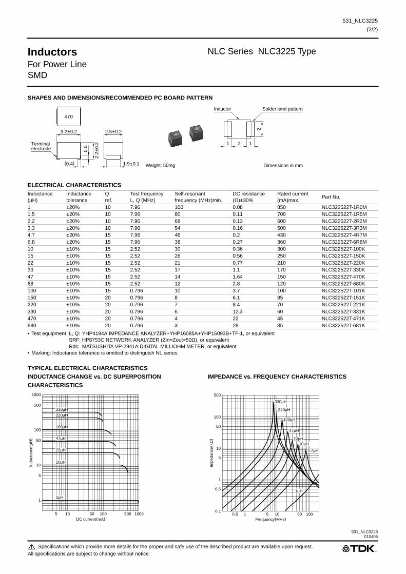
531_NLC3225010405
Specifications which provide more details for the proper and safe use of the described product are available upon request.All specifications are subject to change without notice.
531_NLC3225
(2/2)
Inductors
NLC Series NLC3225 Type
For Power LineSMD
SHAPES AND DIMENSIONS/RECOMMENDED PC BOARD PATTERN
ELECTRICAL CHARACTERISTICS
• Test equipment L, Q: YHP4194A IMPEDANCE ANALYZER+YHP16085A+YHP16093B+TF-1, or equivalentSRF: HP8753C NETWORK ANALYZER (Zin=Zout=50
Ω
), or equivalentRdc: MATSUSHITA VP-2941A DIGITAL MILLIOHM METER, or equivalent
• Marking: Inductance tolerance is omitted to distinguish NL series.
TYPICAL ELECTRICAL CHARACTERISTICSINDUCTANCE CHANGE vs. DC SUPERPOSITIONCHARACTERISTICS
IMPEDANCE vs. FREQUENCY CHARACTERISTICS
Inductance(µH)
Inductancetolerance
Qref.
Test frequencyL, Q (MHz)
Self-resonantfrequency (MHz)min.
DC resistance(
Ω
)±30%Rated current(mA)max.
Part No.
1 ±20% 10 7.96 100 0.08 850 NLC322522T-1R0M1.5 ±20% 10 7.96 80 0.11 700 NLC322522T-1R5M2.2 ±20% 10 7.96 68 0.13 600 NLC322522T-2R2M3.3 ±20% 10 7.96 54 0.16 500 NLC322522T-3R3M4.7 ±20% 15 7.96 46 0.2 430 NLC322522T-4R7M6.8 ±20% 15 7.96 38 0.27 360 NLC322522T-6R8M10 ±10% 15 2.52 30 0.36 300 NLC322522T-100K15 ±10% 15 2.52 26 0.56 250 NLC322522T-150K22 ±10% 15 2.52 21 0.77 210 NLC322522T-220K33 ±10% 15 2.52 17 1.1 170 NLC322522T-330K47 ±10% 15 2.52 14 1.64 150 NLC322522T-470K68 ±10% 15 2.52 12 2.8 120 NLC322522T-680K100 ±10% 15 0.796 10 3.7 100 NLC322522T-101K150 ±10% 20 0.796 8 6.1 85 NLC322522T-151K220 ±10% 20 0.796 7 8.4 70 NLC322522T-221K330 ±10% 20 0.796 6 12.3 60 NLC322522T-331K470 ±10% 20 0.796 4 22 45 NLC322522T-471K680 ±10% 20 0.796 3 28 35 NLC322522T-681K
470
3.2±0.2 2.5±0.2
1.9±0.1 Weight: 50mg
2.2
±0.2
0.5
(0.4)
Terminalelectrode
Solder land patternInductor
2
1 12
Dimensions in mm
5 10 50 500100 1000
5
10
1
50
100
500
1000
Indu
ctan
ce( µ
H)
DC current(mA)
47µH
22µH
330µH220µH
100µH
10µH
1µH
Frequency(MHz)10.5 105 10050
0.1
1
10
5
0.5
100
50
500
Impe
danc
e( k
Ω)
330µH
220µH
100µH
47µH
22µH
4.7µH
10µH
1µH
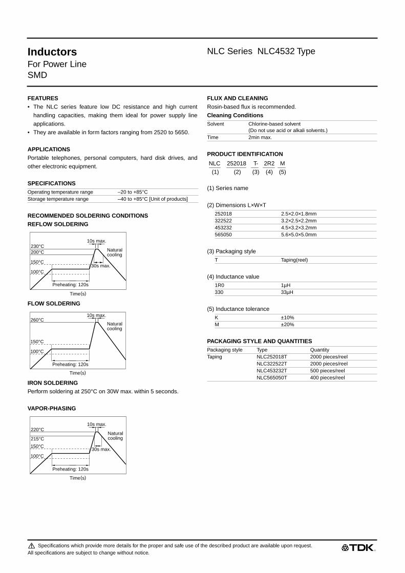
Inductors NLC Series NLC4532 Type
For Power LineSMD
FEATURES• The NLC series feature low DC resistance and high current
handling capacities, making them ideal for power supply line
applications.
• They are available in form factors ranging from 2520 to 5650.
APPLICATIONSPortable telephones, personal computers, hard disk drives, and
other electronic equipment.
SPECIFICATIONS
RECOMMENDED SOLDERING CONDITIONSREFLOW SOLDERING
FLOW SOLDERING
IRON SOLDERINGPerform soldering at 250°C on 30W max. within 5 seconds.
VAPOR-PHASING
FLUX AND CLEANINGRosin-based flux is recommended.
Cleaning Conditions
PRODUCT IDENTIFICATION
(1) Series name
(2) Dimensions L×W×T
(3) Packaging style
(4) Inductance value
(5) Inductance tolerance
PACKAGING STYLE AND QUANTITIES
Operating temperature range –20 to +85°CStorage temperature range –40 to +85°C [Unit of products]
30s max.
Preheating: 120s
10s max.
100°C
200°C230°C
150°C
Naturalcooling
Time(s)
Preheating: 120s
10s max.
100°C
260°C
150°C
Naturalcooling
Time(s)
Preheating: 120s
10s max.
100°C
215°C
220°C
150°C
Naturalcooling
30s max.
Time(s)
Solvent Chlorine-based solvent(Do not use acid or alkali solvents.)
Time 2min max.
252018 2.5×2.0×1.8mm322522 3.2×2.5×2.2mm453232 4.5×3.2×3.2mm565050 5.6×5.0×5.0mm
T Taping(reel)
1R0 1µH330 33µH
K ±10%M ±20%
Packaging style Type QuantityTaping NLC252018T 2000 pieces/reel
NLC322522T 2000 pieces/reelNLC453232T 500 pieces/reelNLC565050T 400 pieces/reel
NLC 252018 T- 2R2 M
(1) (2) (3) (4) (5)
Specifications which provide more details for the proper and safe use of the described product are available upon request.All specifications are subject to change without notice.

Inductors NLC Series NLC4532 Type
For Power LineSMD
SHAPES AND DIMENSIONS/RECOMMENDED PC BOARD PATTERN
ELECTRICAL CHARACTERISTICS
• Test equipment L, Q: YHP4194A IMPEDANCE ANALYZER+YHP16085A+YHP16093B+TF-1, or equivalentSRF: HP8753C NETWORK ANALYZER (Zin=Zout=50Ω), or equivalentRdc: MATSUSHITA VP-2941A DIGITAL MILLIOHM METER, or equivalent
• Marking: Inductance tolerance is omitted to distinguish NL series.
Inductance(µH)
Inductancetolerance
Qmin.
Test frequencyL, Q (MHz)
Self-resonantfrequency (MHz)min.
DC resistance(Ω)max.
Rated current(mA)max.
Part No.
1 ±10% 10 7.96 200 0.11 1050 NLC453232T-1R0K1.2 ±10% 10 7.96 160 0.12 1000 NLC453232T-1R2K1.5 ±10% 10 7.96 130 0.15 950 NLC453232T-1R5K1.8 ±10% 10 7.96 100 0.16 900 NLC453232T-1R8K2.2 ±10% 10 7.96 80 0.18 850 NLC453232T-2R2K2.7 ±10% 10 7.96 60 0.2 800 NLC453232T-2R7K3.3 ±10% 10 7.96 45 0.22 750 NLC453232T-3R3K3.9 ±10% 10 7.96 40 0.24 700 NLC453232T-3R9K4.7 ±10% 10 7.96 35 0.27 650 NLC453232T-4R7K5.6 ±10% 10 7.96 30 0.3 650 NLC453232T-5R6K6.8 ±10% 10 7.96 28 0.35 600 NLC453232T-6R8K8.2 ±10% 10 7.96 25 0.4 600 NLC453232T-8R2K10 ±10% 10 2.52 22 0.5 550 NLC453232T-100K12 ±10% 10 2.52 21 0.6 500 NLC453232T-120K15 ±10% 10 2.52 20 0.7 450 NLC453232T-150K18 ±10% 10 2.52 19 0.8 400 NLC453232T-180K22 ±10% 10 2.52 18 0.9 370 NLC453232T-220K27 ±10% 10 2.52 16 1.2 330 NLC453232T-270K33 ±10% 10 2.52 14 1.4 300 NLC453232T-330K39 ±10% 10 2.52 12 1.6 280 NLC453232T-390K47 ±10% 10 2.52 11.5 1.9 260 NLC453232T-470K56 ±10% 10 2.52 11 2.2 240 NLC453232T-560K68 ±10% 10 2.52 10 2.6 220 NLC453232T-680K82 ±10% 10 2.52 9 3.5 200 NLC453232T-820K100 ±10% 20 0.796 8 4 180 NLC453232T-101K120 ±10% 20 0.796 7.5 4.5 160 NLC453232T-121K150 ±10% 20 0.796 7 6.5 140 NLC453232T-151K180 ±10% 20 0.796 6.5 7.5 120 NLC453232T-181K220 ±10% 20 0.796 5.5 9 120 NLC453232T-221K270 ±10% 20 0.796 5 11 100 NLC453232T-271K330 ±10% 20 0.796 4 13 90 NLC453232T-331K
120
C0.5
R0.2
4.5±0.3 3.2±0.2
2.6±0.1 Weight: 180mg
3.2
±0.2
0.5
(0.4)
Terminalelectrode
Solder land patternInductor
2.8
1.5 1.53
Dimensions in mm
Specifications which provide more details for the proper and safe use of the described product are available upon request.All specifications are subject to change without notice.
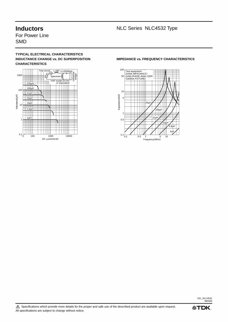
531_NLC4532
Inductors NLC Series NLC4532 Type
For Power LineSMD
TYPICAL ELECTRICAL CHARACTERISTICSINDUCTANCE CHANGE vs. DC SUPERPOSITIONCHARACTERISTICS
IMPEDANCE vs. FREQUENCY CHARACTERISTICS
0.1
1
10
100
1000
Indu
ctan
ce( µ
H)
0 100 1000 10000DC current(mA)
220µH
100µH
47µH
22µH
10µH
3.9µH
1µH
AL=5H C=20000µFTest circuit
DC
Uni
vers
albr
idgeSpecimen
YHP model-4275Aor equivalent
0.1
1
10
5
0.5
100
50
Frequency(MHz)0.1 10.5 105
Impe
danc
e( k
Ω)
Test equipment:4194A IMPEDANCE/GAIN-PHASE ANALYZER(16092A FIXTURE)
1µH
3.9µH
10µH
100µH
22µH
220µH
980406
Specifications which provide more details for the proper and safe use of the described product are available upon request.All specifications are subject to change without notice.

Specifications which provide more details for the proper and safe use of the described product are available upon request.All specifications are subject to change without notice.
531_NLCV25
(1/2)
Inductors
NLCV Series NLCV25 Type
For Power LineSMD
FEATURES
• Provides high Q while using 252018 size winding construction.
• Environmentally friendly due to use of recyclable plastic (ther-
moplastic).
• Logo omitted to simplify production.
• Maintains interchangeability with earlier NL product series.
• NLV series are E-6 products, while NLCV and NLFV series are
E-3 products.
APPLICATIONS
PCs, hard disk drives, and other types of electronics
SPECIFICATIONS
RECOMMENDED SOLDERING CONDITIONSREFLOW SOLDERING
FLOW SOLDERING
IRON SOLDERING
Perform soldering at 250°C on 30W max. within 5 seconds.
VAPOR-PHASING
PRODUCT IDENTIFICATION
(1) Series name
(2) Dimensions LxWxT
(3) Packaging style
(4) Inductance value
(5) Inductance tolerance
PACKAGING STYLE AND QUANTITIES
PRECAUTIONS
• The exterior of this product can melt since due to thermoplastic
construction. During mechanical contact while at the plastic soft-
ening temperature, deformation can occur at the contact loca-
tion. Therefore caution is required when utilizing a soldering iron
during the soldering operation.
FLUX AND CLEANING
Rosin-based flux is recommended.
Cleaning Conditions
TypeOperating temperature range
Storage temperature range[Unit of products]
NLV25 –20 to +85°C –40 to +85°CNLCV25 –20 to +85°C –40 to +85°CNLFV25 –20 to +85°C –40 to +85°C
30s max.
10s max.
100°C
200°C230°C
150°C
Preheating:120s
Naturalcooling
Time(s)
10s max.
100°C
260°C
150°C
Preheating:120s
Naturalcooling
Time(s)
Preheating:120s
10s max.
100°C
215°C
220°C
150°C
Naturalcooling
30s max.
Time(s)
252018 2.5×
2.0×
1.8mm
T Taping (reel)
1R0 1µ
H220 22µ
H
J ±5%K ±10%M ±20%
Packaging style Type QuantityTaping NLV25T 2000 pieces/reel
NLCV25T 2000 pieces/reelNLFV25T 2000 pieces/reel
SolventChlorine-based solvent(Do not use acid or alkali solvents.)
Time 2min max.
NLV 25 T- 2R2 J
(1) (2) (3) (4) (5)

531_NLCV25
000120
Specifications which provide more details for the proper and safe use of the described product are available upon request.All specifications are subject to change without notice.
531_NLCV25
(2/2)
Inductors
NLCV Series NLCV25 Type
For Power LineSMD
SHAPES AND DIMENSIONS/RECOMMENDED PC BOARD PATTERN
ELECTRICAL CHARACTERISTICS
• Test equipment L, Q: HP4194A IMPEDANCE/GAIN PHASE ANALYZER+HP16085A+HP16093 B+TF-1SRF: HP8753C NETWORK ANALYZERRdc: MATSUSHITA VP-2941A DIGITAL MILLIOHM METER
TYPICAL ELECTRICAL CHARACTERISTICSINDUCTANCE CHANGE vs. DC SUPERPOSITION IMPEDANCE vs. FREQUENCY CHARACTERISTICSCHARACTERISTICS
Inductance(µH)Inductance tolerance
Qtyp.
Test frequency L,Q(MHz)
Self-resonant frequency(MHz)min.
DC resistance(Ω
)±30%Rated current(mA)max.
Part No.
1 ±20% 20 7.96 200 0.34 475 NLCV25T-1R0M2.2 ±20% 20 7.96 95 0.5 390 NLCV25T-2R2M4.7 ±20% 20 7.96 43 0.8 285 NLCV25T-4R7M10 ±10% 30 2.52 32 1.69 210 NLCV25T-100K22 ±10% 30 2.52 18 2.8 160 NLCV25T-220K
2.5±0.2 2±0.1
1.8
±0.1
0.5
(0.4)
Terminalelectrode
1.4±0.1 Weight:25mg
1.5
Inductor
Solder land pattern
1.01.51.0 Dimensions in mm
10 30 100 300 1000 3000 10000DC current(mA)
Indu
ctan
ce( µ
H)
0.1
0.3
1
3
10
30
100
22µH
10µH
4.7µH
2.2µH
1µH
1 3 10 30 100 300 1000Frequency(MHz)
Impe
danc
e(kΩ
)
0.1
0.3
1
3
10
30
100
22µH
10µH
4.7µH
2.2µH
1µH

Specifications which provide more details for the proper and safe use of the described product are available upon request.All specifications are subject to change without notice.
531_NLFC2016
(1/2)
Inductors
NLFC Series NLFC2016 Type
For Power LineSMD
FEATURES
• The NLFC series features magnetic shielding and is recom-
mended for power supply line applications.
• They are available in 4 form factors ranging from 2016 to 4532.
APPLICATIONS
Personal computers, hard disk drives, and other electronic equip-
ment.
SPECIFICATIONS
RECOMMENDED SOLDERING CONDITIONSREFLOW SOLDERING
FLOW SOLDERING
IRON SOLDERING
Perform soldering at 250°C on 30W max. within 5 seconds.
VAPOR-PHASING
FLUX AND CLEANING
Rosin-based flux is recommended.
Cleaning Conditions
PRODUCT IDENTIFICATION
(1)Series name
(2)Dimensions L
×
W
×
T
(3)Packaging style
(4)Inductance value
(5)Inductance tolerance
PACKAGING STYLE AND QUANTITIES
TypeOperating temperaturerange
Storage temperaturerange [Unit of products]
NLFC201614 –20 to +80°C –40 to +85°CNLFC252018 –20 to +80°C –40 to +85°CNLFC322522 –20 to +80°C –40 to +85°CNLFC453232 –20 to +80°C –40 to +80°C
30s max.
Preheating: 120s
10s max.
100°C
200°C230°C
150°C
Naturalcooling
Time(s)
Preheating: 120s
10s max.
100°C
260°C
150°C
Naturalcooling
Time(s)
Preheating: 120s
10s max.
100°C
215°C
220°C
150°C
Naturalcooling
30s max.
Time(s)
Solvent Chlorine-based solvent(Do not use acid or alkali solvents.)
Time 2min max.
201614 2.1
×
1.6
×
1.4mm252018 2.5
×
2.0
×
1.8mm322522 3.2
×
2.5
×
2.2mm453232 4.5
×
3.2
×
3.2mm
T Taping (reel)
1R0 1
µ
H220 22
µ
H
K ±10%M ±20%
Packaging style Type QuantityTaping NLFC201614T 2000 pieces/reel
NLFC252018T 2000 pieces/reelNLFC322522T 2000 pieces/reelNLFC453232T 500 pieces/reel
NLFC 201614 T- 2R2 M
(1) (2) (3) (4) (5)

531_NLFC2016010405
Specifications which provide more details for the proper and safe use of the described product are available upon request.All specifications are subject to change without notice.
531_NLFC2016
(2/2)
Inductors
NLFC Series NLFC2016 Type
For Power LineSMD
SHAPES AND DIMENSIONS/RECOMMENDED PC BOARD PATTERN
ELECTRICAL CHARACTERISTICS
∗
Rated current: Value obtained when current flows and the temperature has risen to 20°C or when DC current flows and the initial value of inductance has fallen by 10%, whichever is smaller.
• Test equipment L, Q: YHP4194A IMPEDANCE ANALYZER+YHP16085A+YHP16093B+TF-1, or equivalentSRF: HP8753C NETWORK ANALYZER (Zin=Zout=50
Ω
), or equivalentRdc: MATSUSHITA VP-2941A DIGITAL MILLIOHM METER, or equivalent
TYPICAL ELECTRICAL CHARACTERISTICSINDUCTANCE vs. FREQUENCY CHARACTERISTICS IMPEDANCE vs. FREQUENCY CHARACTERISTICS
INDUCTANCE CHANGE vs. DC SUPERPOSITION Q vs. FREQUENCY CHARACTERISTICSCHARACTERISTICS
Inductance(µH)
Inductancetolerance
Qref.
Test frequencyL, Q (MHz)
Self-resonantfrequency(MHz)min.
DCresistance(
Ω
)±30%
Rated current (mA)
∗
max.
Part No.Based oninductance change
Based on temperature rise
1 ±20% 5 7.96 100 0.16 300 700 NLFC201614T-1R0M2.2 ±20% 5 7.96 80 0.23 240 620 NLFC201614T-2R2M4.7 ±20% 5 7.96 45 0.4 150 430 NLFC201614T-4R7M10 ±10% 10 2.52 32 0.7 120 300 NLFC201614T-100K22 ±10% 10 2.52 16 1.7 75 220 NLFC201614T-220K
2.1±0.2 1.6±0.2
1.4
±0.2
0.5
(0.4)
Terminalelectrode
0.8±0.1 Weight: 15mg
1
Inductor
Solder land pattern
0.810.8
Dimensions in mm
0.1 0.3 1 3 10 30 100Frequency(MHz)
Indu
ctan
ce( µ
H)
0.3
1
3
10
30
100
22µH
10µH
4.7µH
2.2µH
1µH
4194A IMPEDANCE/GAIN-PHASE ANALYZER
0.1 0.3 1 3 10 30 100Frequency(MHz)
Impe
danc
e( Ω
)
10
30
100
300
1k
3k
10k
22µH
10µH
4.7µH
2.2µH
1µH
4194A IMPEDANCE/GAIN-PHASEANALYZER
0.1 0.3 1 3 10 30 100Frequency(MHz)
Q
0
15
10
5
1µH
22µH
4194A IMPEDANCE/GAIN-PHASE ANALYZER
22µH
10µH
4.7µH
2.2µH
1µH
1 3 10 30 100 300 1000DC current(mA)
0.3
1
3
10
30
100
Indu
ctan
ce( µ
H)
1
AL=0.1HC=20000µFTest circuit
DC
Uni
vers
albr
idgeSpecimen
YHP model-4275A or equivalent

Specifications which provide more details for the proper and safe use of the described product are available upon request.All specifications are subject to change without notice.
531_NLFC2520
(1/2)
Inductors
NLFC Series NLFC2520 Type
For Power LineSMD
FEATURES
• The NLFC series features magnetic shielding and is recom-
mended for power supply line applications.
• They are available in 4 form factors ranging from 2016 to 4532.
APPLICATIONS
Personal computers, hard disk drives, and other electronic equip-
ment.
SPECIFICATIONS
RECOMMENDED SOLDERING CONDITIONSREFLOW SOLDERING
FLOW SOLDERING
IRON SOLDERING
Perform soldering at 250°C on 30W max. within 5 seconds.
VAPOR-PHASING
FLUX AND CLEANING
Rosin-based flux is recommended.
Cleaning Conditions
PRODUCT IDENTIFICATION
(1)Series name
(2)Dimensions L
×
W
×
T
(3)Packaging style
(4)Inductance value
(5)Inductance tolerance
PACKAGING STYLE AND QUANTITIES
TypeOperating temperaturerange
Storage temperaturerange [Unit of products]
NLFC201614 –20 to +80°C –40 to +85°CNLFC252018 –20 to +80°C –40 to +85°CNLFC322522 –20 to +80°C –40 to +85°CNLFC453232 –20 to +80°C –40 to +80°C
30s max.
Preheating: 120s
10s max.
100°C
200°C230°C
150°C
Naturalcooling
Time(s)
Preheating: 120s
10s max.
100°C
260°C
150°C
Naturalcooling
Time(s)
Preheating: 120s
10s max.
100°C
215°C
220°C
150°C
Naturalcooling
30s max.
Time(s)
Solvent Chlorine-based solvent(Do not use acid or alkali solvents.)
Time 2min max.
201614 2.1
×
1.6
×
1.4mm252018 2.5
×
2.0
×
1.8mm322522 3.2
×
2.5
×
2.2mm453232 4.5
×
3.2
×
3.2mm
T Taping (reel)
1R0 1
µ
H220 22
µ
H
K ±10%M ±20%
Packaging style Type QuantityTaping NLFC201614T 2000 pieces/reel
NLFC252018T 2000 pieces/reelNLFC322522T 2000 pieces/reelNLFC453232T 500 pieces/reel
NLFC 201614 T- 2R2 M
(1) (2) (3) (4) (5)

531_NLFC2520 010405
Specifications which provide more details for the proper and safe use of the described product are available upon request.All specifications are subject to change without notice.
531_NLFC2520
(2/2)
Inductors
NLFC Series NLFC2520 Type
For Power LineSMD
SHAPES AND DIMENSIONS/RECOMMENDED PC BOARD PATTERN
ELECTRICAL CHARACTERISTICS
• Inductance tolerance: Value of inductance corresponds to inductance value of standard products.• Test equipment L, Q: YHP4194A IMPEDANCE ANALYZER+YHP16085A+YHP16093B+TF-1
SRF: HP8753C NETWORK ANALYZERRdc: MATSUSHITA VP-2941A DIGITAL MILLIOHM METER
TYPICAL ELECTRICAL CHARACTERISTICSINDUCTANCE vs. FREQUENCY CHARACTERISTICS IMPEDANCE vs. FREQUENCY CHARACTERISTICS
Inductance(µH)
Inductancetolerance
Qref.
Test frequencyL, Q (MHz)
Self-resonantfrequency(MHz)min.
DCresistance(
Ω
)±30%
Rated current(mA) max.
Part No.
1 ±20% 10 7.96 100 0.13 455 NLFC252018T-1R0M1.5 ±20% 10 7.96 80 0.17 350 NLFC252018T-1R5M2.2 ±20% 10 7.96 70 0.2 315 NLFC252018T-2R2M3.3 ±20% 10 7.96 55 0.25 280 NLFC252018T-3R3M4.7 ±20% 10 7.96 45 0.3 210 NLFC252018T-4R7M6.8 ±20% 10 7.96 38 0.35 175 NLFC252018T-6R8M10 ±10% 20 2.52 32 0.5 155 NLFC252018T-100K15 ±10% 20 2.52 28 0.75 130 NLFC252018T-150K22 ±10% 20 2.52 16 1.6 105 NLFC252018T-220K33 ±10% 20 2.52 14 2.1 85 NLFC252018T-330K47 ±10% 20 2.52 11 2.6 60 NLFC252018T-470K68 ±10% 20 2.52 10 3.3 50 NLFC252018T-680K100 ±10% 20 0.796 8 5.5 40 NLFC252018T-101K
10
2.5±0.2 2±0.2
1.8
±0.2
0.5
Terminalelectrode
(0.4) 1.4±0.1 Weight: 25mg
1.5
Inductor
Solder land pattern
1.01.51.0
Dimensions in mm
1
3
DC current(mA)1 3010 100 3003 30001000 10000
0.3
0.1
10
100
30
1000
300
Indu
ctan
ce( µ
H)
100µH
10µH
1µH
AL=0.1HC=20000µFTest circuit
DC
Uni
vers
albr
idgeSpecimen
YHP model-4275Aor equivalent
Frequency(MHz)0.1 1 30.3 3010 100
0.1
0.03
0.01
1
10
3
0.3
100
30
Impe
danc
e( k
Ω)
100µH
10µH
1µH
Specifications which provide more details for the proper and safe use of the described product are available upon request.All specifications are subject to change without notice.
531_NLFC3225
(1/2)
Inductors
NLFC Series NLFC3225 Type
For Power LineSMD
FEATURES
• The NLFC series features magnetic shielding and is recom-
mended for power supply line applications.
• They are available in 4 form factors ranging from 2016 to 4532.
APPLICATIONS
Personal computers, hard disk drives, and other electronic equip-
ment.
SPECIFICATIONS
RECOMMENDED SOLDERING CONDITIONSREFLOW SOLDERING
FLOW SOLDERING
IRON SOLDERING
Perform soldering at 250°C on 30W max. within 5 seconds.
VAPOR-PHASING
FLUX AND CLEANING
Rosin-based flux is recommended.
Cleaning Conditions
PRODUCT IDENTIFICATION
(1)Series name
(2)Dimensions L
×
W
×
T
(3)Packaging style
(4)Inductance value
(5)Inductance tolerance
PACKAGING STYLE AND QUANTITIES
TypeOperating temperaturerange
Storage temperaturerange [Unit of products]
NLFC201614 –20 to +80°C –40 to +85°CNLFC252018 –20 to +80°C –40 to +85°CNLFC322522 –20 to +80°C –40 to +85°CNLFC453232 –20 to +80°C –40 to +80°C
30s max.
Preheating: 120s
10s max.
100°C
200°C230°C
150°C
Naturalcooling
Time(s)
Preheating: 120s
10s max.
100°C
260°C
150°C
Naturalcooling
Time(s)
Preheating: 120s
10s max.
100°C
215°C
220°C
150°C
Naturalcooling
30s max.
Time(s)
Solvent Chlorine-based solvent(Do not use acid or alkali solvents.)
Time 2min max.
201614 2.1
×
1.6
×
1.4mm252018 2.5
×
2.0
×
1.8mm322522 3.2
×
2.5
×
2.2mm453232 4.5
×
3.2
×
3.2mm
T Taping (reel)
1R0 1
µ
H220 22
µ
H
K ±10%M ±20%
Packaging style Type QuantityTaping NLFC201614T 2000 pieces/reel
NLFC252018T 2000 pieces/reelNLFC322522T 2000 pieces/reelNLFC453232T 500 pieces/reel
NLFC 201614 T- 2R2 M (1) (2) (3) (4) (5)

531_NLFC3225010405
Specifications which provide more details for the proper and safe use of the described product are available upon request.All specifications are subject to change without notice.
531_NLFC3225
(2/2)
Inductors
NLFC Series NLFC3225 Type
For Power LineSMD
SHAPES AND DIMENSIONS/RECOMMENDED PC BOARD PATTERN
ELECTRICAL CHARACTERISTICS
∗
Rated current: Value obtained when current flows and the temperature has risen to 20°C or when DC current flows and the initial value of inductance has fallen by 10%, whichever is smaller.
• Test equipment L, Q: YHP4194A IMPEDANCE ANALYZER+YHP16085A+YHP16093B+TF-1, or equivalentSRF:HP8753C NETWORK ANALYZER (Zin=Zout=50
Ω
), or equivalentRdc: MATSUSHITA VP-2941A DIGITAL MILLIOHM METER, or equivalent
TYPICAL ELECTRICAL CHARACTERISTICSINDUCTANCE CHANGE vs. DC SUPERPOSITION CHARACTERISTICS
IMPEDANCE vs. FREQUENCY CHARACTERISTICS
Inductance(µH)
Inductancetolerance
Qref.
Test frequencyL, Q (MHz)
Self-resonantfrequency(MHz)min.
DCresistance(
Ω
)±30%
Rated current (mA)
∗
max.Part No.Based on inductance
changeBased on temperature rise
1 ±20% 5 7.96 100 0.06 500 1250 NLFC322522T-1R0M1.5 ±20% 5 7.96 80 0.08 400 1100 NLFC322522T-1R5M2.2 ±20% 5 7.96 68 0.09 340 1000 NLFC322522T-2R2M3.3 ±20% 5 7.96 54 0.11 270 900 NLFC322522T-3R3M4.7 ±20% 5 7.96 46 0.13 240 850 NLFC322522T-4R7M6.8 ±20% 5 7.96 38 0.17 195 750 NLFC322522T-6R8M10 ±10% 10 2.52 30 0.26 165 650 NLFC322522T-100K15 ±10% 10 2.52 26 0.32 145 550 NLFC322522T-150K22 ±10% 10 2.52 21 0.5 115 450 NLFC322522T-220K33 ±10% 10 2.52 17 0.75 95 360 NLFC322522T-330K47 ±10% 10 2.52 14 0.95 85 320 NLFC322522T-470K68 ±10% 10 2.52 12 1.5 70 260 NLFC322522T-680K100 ±10% 10 0.796 10 2.5 55 200 NLFC322522T-101K150 ±10% 10 0.796 8 3.2 45 170 NLFC322522T-151K220 ±10% 10 0.796 7 5.4 35 130 NLFC322522T-221K330 ±10% 10 0.796 5 7 30 110 NLFC322522T-331K470 ±10% 10 0.796 4 16 25 79 NLFC322522T-471K680 ±10% 10 0.796 3 20 20 70 NLFC322522T-681K1000 ±10% 10 0.252 2.4 24 15 63 NLFC322522T-102K
470
3.2±0.2 2.5±0.2
2.2
±0.2
0.5
Terminalelectrode
(0.4) 1.9±0.1 Weight: 50mg
2
Inductor
Solder land pattern
121
Dimensions in mm
DC current(mA)1 10 303 300100 1000
1
0.3
0.1
10
100
30
3
1000
300
Indu
ctan
ce( µ
H)
100µH
47µH
10µH
4.7µH
1µH
330µH AL=5H
C=20000µF
Test circuit
DC
Universal bridge
Specimen
YHP model-4275Aor equivalent
1
3
Frequency(MHz)1 10 303 300100 1000
0.1
0.03
0.01
10
0.3
100
30
Impe
danc
e( k
Ω)
330µH100µH
47µH
4.7µH
10µH
1µH

Specifications which provide more details for the proper and safe use of the described product are available upon request.All specifications are subject to change without notice.
531_NLFC4532
(1/2)
Inductors
NLFC Series NLFC4532 Type
For Power LineSMD
FEATURES
• The NLFC series features magnetic shielding and is recom-
mended for power supply line applications.
• They are available in 4 form factors ranging from 2016 to 4532.
APPLICATIONS
Personal computers, hard disk drives, and other electronic equip-
ment.
SPECIFICATIONS
RECOMMENDED SOLDERING CONDITIONSREFLOW SOLDERING
FLOW SOLDERING
IRON SOLDERING
Perform soldering at 250°C on 30W max. within 5 seconds.
VAPOR-PHASING
FLUX AND CLEANING
Rosin-based flux is recommended.
Cleaning Conditions
PRODUCT IDENTIFICATION
(1)Series name
(2)Dimensions L
×
W
×
T
(3)Packaging style
(4)Inductance value
(5)Inductance tolerance
PACKAGING STYLE AND QUANTITIES
TypeOperating temperaturerange
Storage temperaturerange [Unit of products]
NLFC201614 –20 to +80°C –40 to +85°CNLFC252018 –20 to +80°C –40 to +85°CNLFC322522 –20 to +80°C –40 to +85°CNLFC453232 –20 to +80°C –40 to +80°C
30s max.
Preheating: 120s
10s max.
100°C
200°C230°C
150°C
Naturalcooling
Time(s)
Preheating: 120s
10s max.
100°C
260°C
150°C
Naturalcooling
Time(s)
Preheating: 120s
10s max.
100°C
215°C
220°C
150°C
Naturalcooling
30s max.
Time(s)
Solvent Chlorine-based solvent(Do not use acid or alkali solvents.)
Time 2min max.
201614 2.1
×
1.6
×
1.4mm252018 2.5
×
2.0
×
1.8mm322522 3.2
×
2.5
×
2.2mm453232 4.5
×
3.2
×
3.2mm
T Taping (reel)
1R0 1
µ
H220 22
µ
H
K ±10%M ±20%
Packaging style Type QuantityTaping NLFC201614T 2000 pieces/reel
NLFC252018T 2000 pieces/reelNLFC322522T 2000 pieces/reelNLFC453232T 500 pieces/reel
NLFC 201614 T- 2R2 M (1) (2) (3) (4) (5)

531_NLFC4532010405
Specifications which provide more details for the proper and safe use of the described product are available upon request.All specifications are subject to change without notice.
531_NLFC4532
(2/2)
Inductors
NLFC Series NLFC4532 Type
For Power LineSMD
SHAPES AND DIMENSIONS/RECOMMENDED PC BOARD PATTERN
ELECTRICAL CHARACTERISTICS
∗
Rated current: Value obtained when current flows and the temperature has risen to 20°C or when DC current flows and the initial value of inductance has fallen by 10%, whichever is smaller.
• Test equipment L, Q: YHP4194A IMPEDANCE ANALYZER+YHP16085A+YHP16093B+TF-1, or equivalentSRF:HP8753C NETWORK ANALYZER (Zin=Zout=50
Ω
), or equivalentRdc:MATSUSHITA VP-2941A DIGITAL MILLIOHM METER, or equivalent
TYPICAL ELECTRICAL CHARACTERISTICSINDUCTANCE CHANGE vs. DC SUPERPOSITIONCHARACTERISTICS
IMPEDANCE vs. FREQUENCY CHARACTERISTICS
Inductance(µH)
Inductancetolerance
Qref.
Test frequencyL, Q (MHz)
Self-resonantfrequency(MHz)min.
DCresistance(
Ω
)±30%
Rated current (mA)
∗
max.Part No.Based on inductance
changeBased on temperature rise
1 ±20% 10 7.96 200 0.05 800 1400 NLFC453232T-1R0M1.5 ±20% 10 7.96 130 0.06 700 1200 NLFC453232T-1R5M2.2 ±20% 10 7.96 80 0.07 600 1100 NLFC453232T-2R2M3.3 ±20% 10 7.96 45 0.09 460 1050 NLFC453232T-3R3M4.7 ±20% 10 7.96 35 0.1 400 1000 NLFC453232T-4R7M6.8 ±20% 10 7.96 28 0.14 300 840 NLFC453232T-6R8M10 ±10% 10 2.52 22 0.21 250 690 NLFC453232T-100K15 ±10% 10 2.52 20 0.3 200 570 NLFC453232T-150K22 ±10% 10 2.52 18 0.46 170 460 NLFC453232T-220K33 ±10% 10 2.52 14 0.63 140 400 NLFC453232T-330K47 ±10% 10 2.52 11.5 0.85 120 340 NLFC453232T-470K68 ±10% 10 2.52 10 1.2 100 280 NLFC453232T-680K100 ±10% 10 0.796 8 1.7 90 240 NLFC453232T-101K150 ±10% 10 0.796 7 2.3 65 200 NLFC453232T-151K220 ±10% 10 0.796 5.5 3.8 55 160 NLFC453232T-221K330 ±10% 10 0.796 4 6 45 120 NLFC453232T-331K
120
C0.5
R0.2
4.5±0.3 3.2±0.2
3.2
±0.2
0.5
Terminalelectrode
(0.4) 2.6±0.1 Weight: 180mg Dimensions in mm
2.8
Inductor
Solder land pattern
31.5 1.5
1
3
DC current(mA)10 100 30030 30001000 10000
0.3
0.1
10
100
30
1000
300
Indu
ctan
ce( µ
H)
330µH
100µH
47µH
10µH
4.7µH
1µH
AL=5H C=20000µFTest circuit
DC
Uni
vers
albr
idgeSpecimen
YHP model-4275Aor equivalent
1
3
Frequency(MHz)0.1 1 30.3 3010 100
0.1
0.03
0.01
10
0.3
100
30
Impe
danc
e( k
Ω)
330µH
100µH
47µH
10µH
4.7µH
1µH

Specifications which provide more details for the proper and safe use of the described product are available upon request.All specifications are subject to change without notice.
531_NLFC5650
(1/2)
Inductors
NLFC Series NLFC5650 Type
For Power LineSMD
FEATURES
• The NLFC series features magnetic shielding and is recom-
mended for power supply line applications.
• They are available in 5 form factors ranging from 2016 to 5650.
APPLICATIONS
Personal computers, hard disk drives, and other electronic equip-
ment.
SPECIFICATIONS
RECOMMENDED SOLDERING CONDITIONSREFLOW SOLDERING
FLOW SOLDERING
IRON SOLDERING
Perform soldering at 250°C on 30W max. within 5 seconds.
VAPOR-PHASING
FLUX AND CLEANING
Rosin-based flux is recommended.
Cleaning Conditions
PRODUCT IDENTIFICATION
(1)Series name
(2)Dimensions L
×
W
×
T
(3)Packaging style
(4)Inductance value
(5)Inductance tolerance
PACKAGING STYLE AND QUANTITIES
TypeOperating temperaturerange
Storage temperaturerange [Unit of products]
NLFC201614 –20 to +85°C –40 to +85°CNLFC252018 –20 to +85°C –40 to +85°CNLFC322522 –20 to +85°C –40 to +85°CNLFC453232 –20 to +80°C –40 to +80°CNLFC565050 –20 to +85°C –40 to +85°C
30s max.
Preheating: 120s
10s max.
100°C
200°C230°C
150°C
Naturalcooling
Time(s)
Preheating: 120s
10s max.
100°C
260°C
150°C
Naturalcooling
Time(s)
Preheating: 120s
10s max.
100°C
215°C
220°C
150°C
Naturalcooling
30s max.
Time(s)
Solvent Chlorine-based solvent(Do not use acid or alkali solvents.)
Time 2min max.
201614 2.1
×
1.6
×
1.4mm252018 2.5
×
2.0
×
1.8mm322522 3.2
×
2.5
×
2.2mm453232 4.5
×
3.2
×
3.2mm565050 5.6
×
5.0
×
5.0mm
T Taping (reel)
1R0 1
µ
H220 22
µ
H
K ±10%M ±20%
Packaging style Type Quantity
Taping
NLFC201614T 2000 pieces/reelNLFC252018T 2000 pieces/reelNLFC322522T 2000 pieces/reelNLFC453232T 500 pieces/reelNLFC565050T 400 pieces/reel
NLFC 201614 T- 2R2 M (1) (2) (3) (4) (5)

531_NLFC5650000131
Specifications which provide more details for the proper and safe use of the described product are available upon request.All specifications are subject to change without notice.
531_NLFC5650
(2/2)
Inductors
NLFC Series NLFC5650 Type
For Power LineSMD
SHAPES AND DIMENSIONS/RECOMMENDED PC BOARD PATTERN
ELECTRICAL CHARACTERISTICS
• Inductance tolerance: Value of inductance corresponds to inductance value of standard products.• Test equipment L, Q: YHP4194A IMPEDANCE ANALYZER+YHP16085A+YHP16093B+TF-1
SRF:HP8753C NETWORK ANALYZERRdc:MATSUSHITA VP-2941A DIGITAL MILLIOHM METER
TYPICAL ELECTRICAL CHARACTERISTICSINDUCTANCE CHANGE vs. DC SUPERPOSITIONCHARACTERISTICS IMPEDANCE vs. FREQUENCY CHARACTERISTICS
103
C15.6±0.3 5±0.3
5±0
.3
1
Terminalelectrode
(0.5) 4±0.2 Weight: 380mg Dimensions in mm
4.5
Inductor
Solder land pattern
42 2
Inductance(mH)
Inductancetolerance
Qmin.
Test frequencyL, Q (MHz)
Self-resonantfrequency(MHz)min.
DCresistance(
Ω
)max.
Rated current(mA) max.
Part No.
1.5 ±10% 30 0.252 1.5 7.5 50 NLFC565050T-152K2.2 ±10% 30 0.252 1.2 15 40 NLFC565050T-222K3.3 ±10% 30 0.252 0.8 15 33 NLFC565050T-332K4.7 ±10% 30 0.252 0.6 20 30 NLFC565050T-472K6.8 ±10% 30 0.252 0.5 30 25 NLFC565050T-682K10 ±10% 30 0.0796 0.45 55 20 NLFC565050T-103K15 ±10% 30 0.0796 0.4 90 15 NLFC565050T-153K22 ±10% 30 0.0796 0.35 120 13 NLFC565050T-223K33 ±10% 30 0.0796 0.3 190 11 NLFC565050T-333K47 ±10% 30 0.0796 0.25 250 9 NLFC565050T-473K68 ±10% 30 0.0796 0.2 320 7 NLFC565050T-683K100 ±10% 10 0.01 0.16 480 4 NLFC565050T-104K
1
3
DC current(mA)1 10 303 300100 1000
0.3
0.1
10
100
30
1000
300
Indu
ctan
ce( m
H)
4.7mH
AL=10H C=20000µFTest circuit
DC
Uni
vers
albr
idgeSpecimen
YHP model-4275Aor equivalent
1
3
Frequency(MHz)0.01 0.1 0.30.03 31 10
0.3
0.1
10
100
30
1000
300
Impe
danc
e( k
Ω)
4.7mH

Specifications which provide more details for the proper and safe use of the described product are available upon request.All specifications are subject to change without notice.
531_NLFV25
(1/2)
Inductors
NLFV Series NLFV25 Type
For Power LineSMD
FEATURES
• Provides high Q while using 252018 size winding construction.
• Environmentally friendly due to use of recyclable plastic (ther-
moplastic).
• Logo omitted to simplify production.
• Maintains interchangeability with earlier NL product series.
• NLV series are E-6 products, while NLCV and NLFV series are
E-3 products.
APPLICATIONS
PCs, hard disk drives, and other types of electronics
SPECIFICATIONS
RECOMMENDED SOLDERING CONDITIONSREFLOW SOLDERING
FLOW SOLDERING
IRON SOLDERING
Perform soldering at 250°C on 30W max. within 5 seconds.
VAPOR-PHASING
PRODUCT IDENTIFICATION
(1) Series name
(2) Dimensions LxWxT
(3) Packaging style
(4) Inductance value
(5) Inductance tolerance
PACKAGING STYLE AND QUANTITIES
PRECAUTIONS
• The exterior of this product can melt since due to thermoplastic
construction. During mechanical contact while at the plastic soft-
ening temperature, deformation can occur at the contact loca-
tion. Therefore caution is required when utilizing a soldering iron
during the soldering operation.
FLUX AND CLEANING
Rosin-based flux is recommended.
Cleaning Conditions
TypeOperating temperature range
Storage temperature range[Unit of products]
NLV25 –20 to +85°C –40 to +85°CNLCV25 –20 to +85°C –40 to +85°CNLFV25 –20 to +85°C –40 to +85°C
30s max.
10s max.
100°C
200°C230°C
150°C
Preheating:120s
Naturalcooling
Time(s)
10s max.
100°C
260°C
150°C
Preheating:120s
Naturalcooling
Time(s)
10s max.
100°C
215°C
220°C
150°C 30s max.
Preheating:120s
Naturalcooling
Time(s)
252018 2.5×
2.0×
1.8mm
T Taping (reel)
1R0 1µ
H220 22µ
H
J ±5%K ±10%M ±20%
Packaging style Type QuantityTaping NLV25T 2000 pieces/reel
NLCV25T 2000 pieces/reelNLFV25T 2000 pieces/reel
SolventChlorine-based solvent(Do not use acid or alkali solvents.)
Time 2min max.
NLV 25 T- 2R2 J
(1) (2) (3) (4) (5)

531_NLFV25
000120
Specifications which provide more details for the proper and safe use of the described product are available upon request.All specifications are subject to change without notice.
531_NLFV25
(2/2)
Inductors
NLFV Series NLFV25 Type
For Power LineSMD
SHAPES AND DIMENSIONS/RECOMMENDED PC BOARD PATTERN
ELECTRICAL CHARACTERISTICS
• Test equipment L, Q: HP4194A IMPEDANCE ANALYZER(16085A+16093B+TDK TF-1)SRF: HP8753C NETWORK ANALYZERRdc: MATSUSHITA VP-2941A DIGITAL MILLIOHM METER
TYPICAL ELECTRICAL CHARACTERISTICSINDUCTANCE CHANGE vs. DC SUPERPOSITION IMPEDANCE vs. FREQUENCY CHARACTERISTICSCHARACTERISTICS
Inductance(µH)Inductance tolerance
Qtyp.
Test frequency L,Q(MHz)
Self-resonant frequency(MHz)min.
DC resistance(Ω
)±20%Rated current(mA)max.
Part No.
1 ±20% 5 7.96 100 0.07 455 NLFV25T-1R0M2.2 ±20% 5 7.96 70 0.1 315 NLFV25T-2R2M4.7 ±20% 5 7.96 45 0.24 210 NLFV25T-4R7M10 ±10% 10 2.52 32 0.36 155 NLFV25T-100K22 ±10% 10 2.52 16 1 105 NLFV25T-220K47 ±10% 10 2.52 11 1.7 60 NLFV25T-470K100 ±10% 10 0.796 8 4 40 NLFV25T-101K
2.5±0.2 2±0.1
1.8±
0.1
0.5
(0.4) 1.4±0.1
1.5
1.01.51.0
Terminalelectrode
Weight:25mg
Inductor
Solder land pattern
Dimensions in mm
1
3
1 3010 100 3003 30001000 10000
0.3
0.1
10
100
30
1000
300
100µH
10µH
1µH
AL=0.1HC=20000µFTest circuit
DC
Uni
vers
albr
idgeSpecimen
HP model-4275Aor equivalent
DC current(mA)
Indu
ctan
ce( µ
H)
0.1 1 30.3 3010 100
0.1
0.03
0.01
1
10
3
0.3
100
30100µH
10µH
1µH
Frequency(MHz)
Impe
danc
e(kΩ
)

531_SLF10145
(1/2)
Inductors SLF Series SLF10145 Type
For Power LineSMD
FEATURES• The SLF series are characterized by low profile, low DC
resistance, and high current handling capacities.
• Because they are magnetically shielded, these parts can be
used in high-density mounting configurations.
• Flat bottom surface ensures secure, reliable mounting.
• Provided in embossed carrier tape packaging for use with
automatic mounting machines.
APPLICATIONSPortable telephones, personal computers, hard disk drives, and
other electronic equipment.
SPECIFICATIONS
RECOMMENDED REFLOW SOLDERING CONDITIONS
PRODUCT IDENTIFICATION
(1) Series name
(2) Dimensions L×W×T
(3) Packaging style
(4) Inductance value
(5) Inductance tolerance
(6) Rated current
(7) TDK internal code
(Some products may not have this number. See the main body
for details.)
PACKAGING STYLE AND QUANTITIES
TypeOperating temperature range[Including self-temperature rise]
Storage temperaturerange[Unit of products]
SLF6025 –20 to +85°C –40 to +85°CSLF6028 –20 to +85°C –40 to +85°CSLF7028 –20 to +85°C –40 to +85°CSLF7030 –20 to +85°C –40 to +85°CSLF7032 –20 to +85°C –40 to +85°CSLF7045 –20 to +85°C –40 to +85°CSLF10145 –20 to +90°C –40 to +90°CSLF12555 –20 to +90°C –40 to +90°CSLF12565 –20 to +105°C –40 to +105°CSLF12575 –20 to +105°C –40 to +105°C
40s
60 to 120s
Preheating
5s
Naturalcooling
240±5°C
220±5°C
150°C
130°C
Time(s)
6025 6.0×6.0×2.5mm6028 6.0×6.0×2.8mm7028 7.0×7.0×2.8mm7030 7.0×7.0×3.0mm7032 7.0×7.0×3.2mm7045 7.0×7.0×4.5mm10145 10.1×10.1×4.5mm12555 12.5×12.5×5.5mm12565 12.5×12.5×6.5mm12575 12.5×12.5×7.5mm
T Taping(reel)
3R3 3.3µH100 10µH
M ±20%N ±30%
1R9 1.9AR96 0.96A
Packaging style Type QuantityTaping SLF6025T 1000 pieces/reel
SLF6028T 1000 pieces/reelSLF7028T 1000 pieces/reelSLF7030T 1000 pieces/reelSLF7032T 1000 pieces/reelSLF7045T 1000 pieces/reelSLF10145T 500 pieces/reelSLF12555T 500 pieces/reelSLF12565T 500 pieces/reelSLF12575T 500 pieces/reel
SLF 7032 T- 220 M R96 -2
(1) (2) (3) (4) (5) (6) (7)
Specifications which provide more details for the proper and safe use of the described product are available upon request.All specifications are subject to change without notice.

531_SLF10145
(2/2)
531_SLF10145
Inductors SLF Series SLF10145 Type
For Power LineSMD
SHAPES AND DIMENSIONS/RECOMMENDED PC BOARD PATTERN
ELECTRICAL CHARACTERISTICS
∗ Rated current: Value obtained when current flows and the temperature has risen to 30°C or when DC current flows and the initial value of inductance has fallen by 10%, whichever is smaller.
• Test equipment L:YHP 4194A IMPEDANCE GAIN/PHASE ANALYZER, or equivalent (Measured at 1kHz/0.5V)Rdc:MATSUSHITA VP-2941A DIGITAL MILLIOHM METER, or equivalent
TYPICAL ELECTRICAL CHARACTERISTICSINDUCTANCE CHANGE vs. DC SUPERPOSITIONCHARACTERISTICS
Inductance(µH)
Inductancetolerance (%)
Test frequency L (kHz)
DC resistance(Ω)±20%
Rated current (A)∗ max.Part No.Based on
inductance changeBased ontemperature rise
10 ±20 1 0.0364 3 2.5 SLF10145T-100M2R515 ±20 1 0.0472 2.4 2.2 SLF10145T-150M2R222 ±20 1 0.0591 2.1 1.9 SLF10145T-220M1R933 ±20 1 0.0815 1.6 1.7 SLF10145T-330M1R647 ±20 1 0.1 1.4 1.5 SLF10145T-470M1R468 ±20 1 0.14 1.2 1.3 SLF10145T-680M1R2100 ±20 1 0.2 1 1.1 SLF10145T-101M1R0150 ±20 1 0.35 0.79 0.81 SLF10145T-151MR79220 ±20 1 0.47 0.65 0.7 SLF10145T-221MR65330 ±20 1 0.68 0.54 0.58 SLF10145T-331MR54470 ±20 1 1.03 0.47 0.47 SLF10145T-471MR47680 ±20 1 1.6 0.38 0.38 SLF10145T-681MR381000 ±20 1 2.8 0.32 0.29 SLF10145T-102MR291500 ±20 1 3.4 0.22 0.26 SLF10145T-152MR22
10.1±0.3
Winding start mark
Marking(Inductance code)
10.1
±0.
3
5.6
2.5
2.5
6±0.
22±
0.15
Weight: 1.3g typ.
Dimensions in mm
3±0.1 3.24.5±0.3
0.15typ.
2
20
DC current(A)0.01
3
1
100
1000
300
30
10
10000
3000
0.1 0.30.03 31 10
Indu
ctan
ce( µ
H)
1000µH
330µH
100µH
33µH
10µH
AL=0.1H C=20000µF
Specimen
Test circuit
YHP model-4275A or equivalent
DC
Uni
vers
albr
idge
990803
Specifications which provide more details for the proper and safe use of the described product are available upon request.All specifications are subject to change without notice.

531_SLF12555
(1/2)
Inductors SLF Series SLF12555 Type
For Power LineSMD
FEATURES• The SLF series are characterized by low profile, low DC
resistance, and high current handling capacities.
• Because they are magnetically shielded, these parts can be
used in high-density mounting configurations.
• Flat bottom surface ensures secure, reliable mounting.
• Provided in embossed carrier tape packaging for use with
automatic mounting machines.
APPLICATIONSPortable telephones, personal computers, hard disk drives, and
other electronic equipment.
SPECIFICATIONS
RECOMMENDED REFLOW SOLDERING CONDITIONS
PRODUCT IDENTIFICATION
(1) Series name
(2) Dimensions L×W×T
(3) Packaging style
(4) Inductance value
(5) Inductance tolerance
(6) Rated current
(7) TDK internal code
(Some products may not have this number. See the main body
for details.)
PACKAGING STYLE AND QUANTITIES
TypeOperating temperature range[Including self-temperature rise]
Storage temperaturerange[Unit of products]
SLF6025 –20 to +85°C –40 to +85°CSLF6028 –20 to +85°C –40 to +85°CSLF7028 –20 to +85°C –40 to +85°CSLF7030 –20 to +85°C –40 to +85°CSLF7032 –20 to +85°C –40 to +85°CSLF7045 –20 to +85°C –40 to +85°CSLF10145 –20 to +90°C –40 to +90°CSLF12555 –20 to +90°C –40 to +90°CSLF12565 –20 to +105°C –40 to +105°CSLF12575 –20 to +105°C –40 to +105°C
40s
60 to 120s
Preheating
5s
Naturalcooling
240±5°C
220±5°C
150°C
130°C
Time(s)
6025 6.0×6.0×2.5mm6028 6.0×6.0×2.8mm7028 7.0×7.0×2.8mm7030 7.0×7.0×3.0mm7032 7.0×7.0×3.2mm7045 7.0×7.0×4.5mm10145 10.1×10.1×4.5mm12555 12.5×12.5×5.5mm12565 12.5×12.5×6.5mm12575 12.5×12.5×7.5mm
T Taping(reel)
3R3 3.3µH100 10µH
M ±20%N ±30%
1R9 1.9AR96 0.96A
Packaging style Type QuantityTaping SLF6025T 1000 pieces/reel
SLF6028T 1000 pieces/reelSLF7028T 1000 pieces/reelSLF7030T 1000 pieces/reelSLF7032T 1000 pieces/reelSLF7045T 1000 pieces/reelSLF10145T 500 pieces/reelSLF12555T 500 pieces/reelSLF12565T 500 pieces/reelSLF12575T 500 pieces/reel
SLF 7032 T- 220 M R96 -2
(1) (2) (3) (4) (5) (6) (7)
Specifications which provide more details for the proper and safe use of the described product are available upon request.All specifications are subject to change without notice.
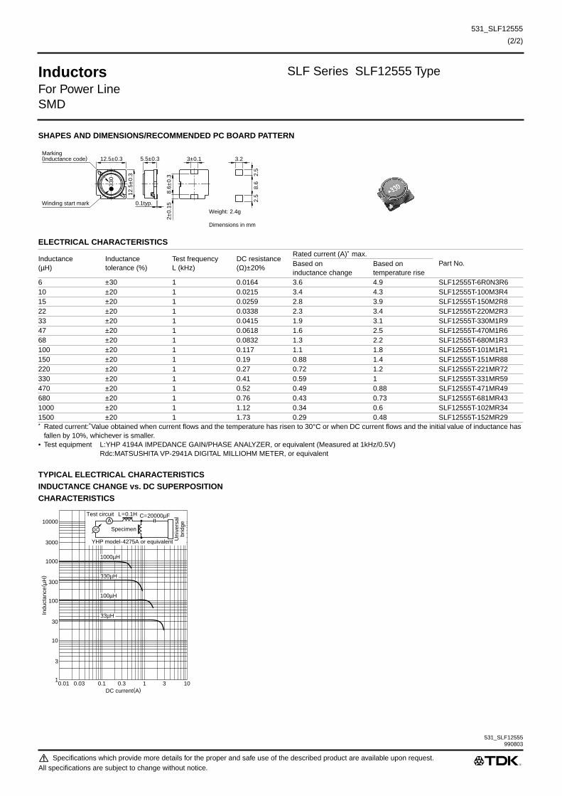
531_SLF12555
(2/2)
531_SLF12555
Inductors SLF Series SLF12555 Type
For Power LineSMD
SHAPES AND DIMENSIONS/RECOMMENDED PC BOARD PATTERN
ELECTRICAL CHARACTERISTICS
∗ Rated current: Value obtained when current flows and the temperature has risen to 30°C or when DC current flows and the initial value of inductance has fallen by 10%, whichever is smaller.
• Test equipment L:YHP 4194A IMPEDANCE GAIN/PHASE ANALYZER, or equivalent (Measured at 1kHz/0.5V)Rdc:MATSUSHITA VP-2941A DIGITAL MILLIOHM METER, or equivalent
TYPICAL ELECTRICAL CHARACTERISTICSINDUCTANCE CHANGE vs. DC SUPERPOSITIONCHARACTERISTICS
Inductance(µH)
Inductancetolerance (%)
Test frequency L (kHz)
DC resistance(Ω)±20%
Rated current (A)∗ max.Part No.Based on
inductance changeBased ontemperature rise
6 ±30 1 0.0164 3.6 4.9 SLF12555T-6R0N3R610 ±20 1 0.0215 3.4 4.3 SLF12555T-100M3R415 ±20 1 0.0259 2.8 3.9 SLF12555T-150M2R822 ±20 1 0.0338 2.3 3.4 SLF12555T-220M2R333 ±20 1 0.0415 1.9 3.1 SLF12555T-330M1R947 ±20 1 0.0618 1.6 2.5 SLF12555T-470M1R668 ±20 1 0.0832 1.3 2.2 SLF12555T-680M1R3100 ±20 1 0.117 1.1 1.8 SLF12555T-101M1R1150 ±20 1 0.19 0.88 1.4 SLF12555T-151MR88220 ±20 1 0.27 0.72 1.2 SLF12555T-221MR72330 ±20 1 0.41 0.59 1 SLF12555T-331MR59470 ±20 1 0.52 0.49 0.88 SLF12555T-471MR49680 ±20 1 0.76 0.43 0.73 SLF12555T-681MR431000 ±20 1 1.12 0.34 0.6 SLF12555T-102MR341500 ±20 1 1.73 0.29 0.48 SLF12555T-152MR29
12.5±0.3
12.5
±0.
3
8.6
2.5
2.5
3
30
Winding start mark
Marking(Inductance code) 3±0.1
8.6±
0.3
2±0.
15
Weight: 2.4g
Dimensions in mm
3.25.5±0.3
0.1typ.
DC current(A)0.01
3
1
100
1000
300
30
10
10000
3000
0.1 0.30.03 31 10
Indu
ctan
ce( µ
H)
1000µH
330µH
100µH
33µH
AL=0.1H C=20000µF
Specimen
Test circuit
YHP model-4275A or equivalent
DC
Uni
vers
albr
idge
990803
Specifications which provide more details for the proper and safe use of the described product are available upon request.All specifications are subject to change without notice.

531_SLF12565
(1/2)
Inductors SLF Series SLF12565 Type
For Power LineSMD
FEATURES• The SLF series are characterized by low profile, low DC
resistance, and high current handling capacities.
• Because they are magnetically shielded, these parts can be
used in high-density mounting configurations.
• Flat bottom surface ensures secure, reliable mounting.
• Provided in embossed carrier tape packaging for use with
automatic mounting machines.
APPLICATIONSPortable telephones, personal computers, hard disk drives, and
other electronic equipment.
SPECIFICATIONS
RECOMMENDED REFLOW SOLDERING CONDITIONS
PRODUCT IDENTIFICATION
(1) Series name
(2) Dimensions L×W×T
(3) Packaging style
(4) Inductance value
(5) Inductance tolerance
(6) Rated current
(7) TDK internal code
(Some products may not have this number. See the main body
for details.)
PACKAGING STYLE AND QUANTITIES
TypeOperating temperature range[Including self-temperature rise]
Storage temperaturerange[Unit of products]
SLF6025 –20 to +85°C –40 to +85°CSLF6028 –20 to +85°C –40 to +85°CSLF7028 –20 to +85°C –40 to +85°CSLF7030 –20 to +85°C –40 to +85°CSLF7032 –20 to +85°C –40 to +85°CSLF7045 –20 to +85°C –40 to +85°CSLF10145 –20 to +90°C –40 to +90°CSLF12555 –20 to +90°C –40 to +90°CSLF12565 –20 to +105°C –40 to +105°CSLF12575 –20 to +105°C –40 to +105°C
40s
60 to 120s
Preheating
5s
Naturalcooling
240±5°C
220±5°C
150°C
130°C
Time(s)
6025 6.0×6.0×2.5mm6028 6.0×6.0×2.8mm7028 7.0×7.0×2.8mm7030 7.0×7.0×3.0mm7032 7.0×7.0×3.2mm7045 7.0×7.0×4.5mm10145 10.1×10.1×4.5mm12555 12.5×12.5×5.5mm12565 12.5×12.5×6.5mm12575 12.5×12.5×7.5mm
T Taping(reel)
3R3 3.3µH100 10µH
M ±20%N ±30%
1R9 1.9AR96 0.96A
Packaging style Type QuantityTaping SLF6025T 1000 pieces/reel
SLF6028T 1000 pieces/reelSLF7028T 1000 pieces/reelSLF7030T 1000 pieces/reelSLF7032T 1000 pieces/reelSLF7045T 1000 pieces/reelSLF10145T 500 pieces/reelSLF12555T 500 pieces/reelSLF12565T 500 pieces/reelSLF12575T 500 pieces/reel
SLF 7032 T- 220 M R96 -2
(1) (2) (3) (4) (5) (6) (7)
Specifications which provide more details for the proper and safe use of the described product are available upon request.All specifications are subject to change without notice.

531_SLF12565
(2/2)
531_SLF12565
Inductors SLF Series SLF12565 Type
For Power LineSMD
SHAPES AND DIMENSIONS/RECOMMENDED PC BOARD PATTERN
ELECTRICAL CHARACTERISTICS
∗ Rated current: Value obtained when current flows and the temperature has risen to 40°C or when DC current flows and the initial value of inductance has fallen by 10%, whichever is smaller.
• Test equipment L:YHP 4194A IMPEDANCE GAIN/PHASE ANALYZER, or equivalent (Measured at 1kHz/0.5V)Rdc:MATSUSHITA VP-2941A DIGITAL MILLIOHM METER, or equivalent
TYPICAL ELECTRICAL CHARACTERISTICSINDUCTANCE CHANGE vs. DC SUPERPOSITIONCHARACTERISTICS
Inductance(µH)
Inductancetolerance (%)
Test frequency L (kHz)
DC resistance(Ω)±20%
Rated current (A)∗ max.Part No.Based on
inductance changeBased ontemperature rise
2 ±30 1 0.0117 10 6.2 SLF12565T-2R0N6R24.2 ±30 1 0.015 7.3 5.5 SLF12565T-4R2N5R57 ±30 1 0.0177 5.7 5 SLF12565T-7R0N5R010 ±20 1 0.0202 5 4.8 SLF12565T-100M4R815 ±20 1 0.0237 4.2 4.4 SLF12565T-150M4R222 ±20 1 0.0316 3.5 3.8 SLF12565T-220M3R533 ±20 1 0.0406 2.8 3.4 SLF12565T-330M2R847 ±20 1 0.0578 2.4 2.8 SLF12565T-470M2R468 ±20 1 0.0787 2 2.4 SLF12565T-680M2R0100 ±20 1 0.123 1.6 1.9 SLF12565T-101M1R6220 ±20 1 0.273 1 1.2 SLF12565T-221M1R0
12.5±0.3
12.5
±0.
3
Winding start mark
Marking(Inductance code) 3±0.1
8.6±
0.3
2±0.
15
Weight: 2.8g
Dimensions in mm
6.5±0.35
0.1typ.
3
30
8.6
2.5
2.5
3.2
DC current(A)0.01
3
1
100
1000
300
30
10
10000
3000
0.1 0.30.03 31 10
Indu
ctan
ce( µ
H)
33µH
68µH
100µH
AL=0.1H C=20000µF
Specimen
Test circuit
YHP model-4275A or equivalent
DC
Uni
vers
albr
idge
990803
Specifications which provide more details for the proper and safe use of the described product are available upon request.All specifications are subject to change without notice.

531_SLF12575
(1/2)
Inductors SLF Series SLF12575 Type
For Power LineSMD
FEATURES• The SLF series are characterized by low profile, low DC
resistance, and high current handling capacities.
• Because they are magnetically shielded, these parts can be
used in high-density mounting configurations.
• Flat bottom surface ensures secure, reliable mounting.
• Provided in embossed carrier tape packaging for use with
automatic mounting machines.
APPLICATIONSPortable telephones, personal computers, hard disk drives, and
other electronic equipment.
SPECIFICATIONS
RECOMMENDED REFLOW SOLDERING CONDITIONS
PRODUCT IDENTIFICATION
(1) Series name
(2) Dimensions L×W×T
(3) Packaging style
(4) Inductance value
(5) Inductance tolerance
(6) Rated current
(7) TDK internal code
(Some products may not have this number. See the main body
for details.)
PACKAGING STYLE AND QUANTITIES
TypeOperating temperature range[Including self-temperature rise]
Storage temperaturerange[Unit of products]
SLF6025 –20 to +85°C –40 to +85°CSLF6028 –20 to +85°C –40 to +85°CSLF7028 –20 to +85°C –40 to +85°CSLF7030 –20 to +85°C –40 to +85°CSLF7032 –20 to +85°C –40 to +85°CSLF7045 –20 to +85°C –40 to +85°CSLF10145 –20 to +90°C –40 to +90°CSLF12555 –20 to +90°C –40 to +90°CSLF12565 –20 to +105°C –40 to +105°CSLF12575 –20 to +105°C –40 to +105°C
40s
60 to 120s
Preheating
5s
Naturalcooling
240±5°C
220±5°C
150°C
130°C
Time(s)
6025 6.0×6.0×2.5mm6028 6.0×6.0×2.8mm7028 7.0×7.0×2.8mm7030 7.0×7.0×3.0mm7032 7.0×7.0×3.2mm7045 7.0×7.0×4.5mm10145 10.1×10.1×4.5mm12555 12.5×12.5×5.5mm12565 12.5×12.5×6.5mm12575 12.5×12.5×7.5mm
T Taping(reel)
3R3 3.3µH100 10µH
M ±20%N ±30%
1R9 1.9AR96 0.96A
Packaging style Type QuantityTaping SLF6025T 1000 pieces/reel
SLF6028T 1000 pieces/reelSLF7028T 1000 pieces/reelSLF7030T 1000 pieces/reelSLF7032T 1000 pieces/reelSLF7045T 1000 pieces/reelSLF10145T 500 pieces/reelSLF12555T 500 pieces/reelSLF12565T 500 pieces/reelSLF12575T 500 pieces/reel
SLF 7032 T- 220 M R96 -2
(1) (2) (3) (4) (5) (6) (7)
Specifications which provide more details for the proper and safe use of the described product are available upon request.All specifications are subject to change without notice.

531_SLF12575
(2/2)
531_SLF12575
Inductors SLF Series SLF12575 Type
For Power LineSMD
SHAPES AND DIMENSIONS/RECOMMENDED PC BOARD PATTERN
ELECTRICAL CHARACTERISTICS
∗ Rated current: Value obtained when current flows and the temperature has risen to 40°C or when DC current flows and the initial value of inductance has fallen by 10%, whichever is smaller.
• Test equipment L:YHP 4194A IMPEDANCE GAIN/PHASE ANALYZER, or equivalent (Measured at 1kHz/0.5V)Rdc:MATSUSHITA VP-2941A DIGITAL MILLIOHM METER, or equivalent
TYPICAL ELECTRICAL CHARACTERISTICSINDUCTANCE CHANGE vs. DC SUPERPOSITIONCHARACTERISTICS
Inductance(µH)
Inductancetolerance (%)
Test frequency L (kHz)
DC resistance(Ω)±20%
Rated current (A)∗ max.Part No.Based on
inductance changeBased ontemperature rise
1.2 ±30 1 0.0069 13 8.2 SLF12575T-1R2N8R22.7 ±30 1 0.0094 10 7 SLF12575T-2R7N7R03.9 ±30 1 0.0104 9 6.7 SLF12575T-3R9N6R75.6 ±30 1 0.0116 7.8 6.3 SLF12575T-5R6N6R36.8 ±30 1 0.0131 7.2 5.9 SLF12575T-6R8N5R910 ±20 1 0.0156 5.5 5.4 SLF12575T-100M5R415 ±20 1 0.0184 4.7 5 SLF12575T-150M4R722 ±20 1 0.0263 4 4 SLF12575T-220M4R033 ±20 1 0.0395 3.2 3.4 SLF12575T-330M3R247 ±20 1 0.0528 2.7 3 SLF12575T-470M2R768 ±20 1 0.0778 2 2.4 SLF12575T-680M2R0100 ±20 1 0.125 1.9 1.9 SLF12575T-101M1R9150 ±20 1 0.175 1.5 1.6 SLF12575T-151M1R5220 ±20 1 0.258 1.3 1.3 SLF12575T-221M1R3
12.5±0.3
12.5
±0.
3
Winding start mark
Marking(Inductance code) 3±0.1
8.6±
0.3
2±0.
15
Weight: 3.3g
Dimensions in mm
7.5±0.35
0.1typ.
3
30
8.6
2.5
2.5
3.2
DC current(A)0.01
3
1
100
1000
300
30
10
10000
3000
0.1 0.30.03 31 10
Indu
ctan
ce( µ
H)
6.8µH
22µH
47µH
100µH
10µH
AL=0.1H C=20000µF
Specimen
Test circuit
YHP model-4275A or equivalent
DC
Uni
vers
albr
idge
990803
Specifications which provide more details for the proper and safe use of the described product are available upon request.All specifications are subject to change without notice.

531_SLF6028
(1/2)
Inductors SLF Series SLF6028 Type
For Power LineSMD
FEATURES• The SLF series are characterized by low profile, low DC
resistance, and high current handling capacities.
• Because they are magnetically shielded, these parts can be
used in high-density mounting configurations.
• Flat bottom surface ensures secure, reliable mounting.
• Provided in embossed carrier tape packaging for use with
automatic mounting machines.
APPLICATIONSPortable telephones, personal computers, hard disk drives, and
other electronic equipment.
SPECIFICATIONS
RECOMMENDED REFLOW SOLDERING CONDITIONS
PRODUCT IDENTIFICATION
(1) Series name
(2) Dimensions L×W×T
(3) Packaging style
(4) Inductance value
(5) Inductance tolerance
(6) Rated current
(7) TDK internal code
(Some products may not have this number. See the main body
for details.)
PACKAGING STYLE AND QUANTITIES
TypeOperating temperature range[Including self-temperature rise]
Storage temperaturerange[Unit of products]
SLF6025 –20 to +85°C –40 to +85°CSLF6028 –20 to +85°C –40 to +85°CSLF7028 –20 to +85°C –40 to +85°CSLF7030 –20 to +85°C –40 to +85°CSLF7032 –20 to +85°C –40 to +85°CSLF7045 –20 to +85°C –40 to +85°CSLF10145 –20 to +90°C –40 to +90°CSLF12555 –20 to +90°C –40 to +90°CSLF12565 –20 to +105°C –40 to +105°CSLF12575 –20 to +105°C –40 to +105°C
40s
60 to 120s
Preheating
5s
Naturalcooling
240±5°C
220±5°C
150°C
130°C
Time(s)
6025 6.0×6.0×2.5mm6028 6.0×6.0×2.8mm7028 7.0×7.0×2.8mm7030 7.0×7.0×3.0mm7032 7.0×7.0×3.2mm7045 7.0×7.0×4.5mm10145 10.1×10.1×4.5mm12555 12.5×12.5×5.5mm12565 12.5×12.5×6.5mm12575 12.5×12.5×7.5mm
T Taping(reel)
3R3 3.3µH100 10µH
M ±20%N ±30%
1R9 1.9AR96 0.96A
Packaging style Type QuantityTaping SLF6025T 1000 pieces/reel
SLF6028T 1000 pieces/reelSLF7028T 1000 pieces/reelSLF7030T 1000 pieces/reelSLF7032T 1000 pieces/reelSLF7045T 1000 pieces/reelSLF10145T 500 pieces/reelSLF12555T 500 pieces/reelSLF12565T 500 pieces/reelSLF12575T 500 pieces/reel
SLF 7032 T- 220 M R96 -2
(1) (2) (3) (4) (5) (6) (7)
Specifications which provide more details for the proper and safe use of the described product are available upon request.All specifications are subject to change without notice.

531_SLF6028
(2/2)
531_SLF6028
Inductors SLF Series SLF6028 Type
For Power LineSMD
SHAPES AND DIMENSIONS/RECOMMENDED PC BOARD PATTERN
ELECTRICAL CHARACTERISTICS
∗ Rated current: Value obtained when current flows and the temperature has risen to 25°C or when DC current flows and the initial value of inductance has fallen by 30%, whichever is smaller.
• Test equipment Inductance: YHP 4194A IMPEDANCE GAIN/PHASE ANALYZER, or equivalent (Test frequency: 1kHz/0.5V)Rdc: DIGITAL MILLIOHM METER VP-2941A MATSUSHITA, or equivalent
TYPICAL ELECTRICAL CHARACTERISTICSINDUCTANCE CHANGE vs. DC SUPERPOSITIONCHARACTERISTICS
Inductance(µH)
Inductancetolerance (%)
Test frequency L (kHz)
DC resistance(Ω)±20%
Rated current (A)∗
Part No.Based on inductancechange
Based ontemperature rise
4.7 ±20 1 0.0284 1.6max. 2.5typ. SLF6028T-4R7M1R66.8 ±20 1 0.0354 1.5max. 2.2typ. SLF6028T-6R8M1R510 ±20 1 0.0532 1.3max. 1.8typ. SLF6028T-100M1R315 ±20 1 0.0745 1max. 1.4typ. SLF6028T-150M1R022 ±20 1 0.104 0.77max. 1.3typ. SLF6028T-220MR7733 ±20 1 0.148 0.69max. 1.1typ. SLF6028T-330MR6947 ±20 1 0.21 0.59max. 0.92typ. SLF6028T-470MR5968 ±20 1 0.29 0.5max. 0.78typ. SLF6028T-680MR50100 ±20 1 0.43 0.42max. 0.64typ. SLF6028T-101MR42
6±0.2
Marking(Inductance code)
Winding start mark
6±
0.2
41.
51.
5
4typ
.( 0
.9)
Weight: 0.3g typ.
Dimensions in mm
2±0.1 2.22.8±0.2
(0.05typ.)
220
10µH
15µH22µH
33µH
DC current(A)0.01
3
1
100
1000
300
30
10
10000
3000
0.1 0.30.03 31 10
Indu
ctan
ce( µ
H)
AL=0.1H C=20000µF
Specimen
Test circuit
YHP model-4275A or equivalent
DC
LCR
met
er
990803
Specifications which provide more details for the proper and safe use of the described product are available upon request.All specifications are subject to change without notice.

531_SLF7028
(1/2)
Inductors SLF Series SLF7028 Type
For Power LineSMD
FEATURES• The SLF series are characterized by low profile, low DC
resistance, and high current handling capacities.
• Because they are magnetically shielded, these parts can be
used in high-density mounting configurations.
• Flat bottom surface ensures secure, reliable mounting.
• Provided in embossed carrier tape packaging for use with
automatic mounting machines.
APPLICATIONSPortable telephones, personal computers, hard disk drives, and
other electronic equipment.
SPECIFICATIONS
RECOMMENDED REFLOW SOLDERING CONDITIONS
PRODUCT IDENTIFICATION
(1) Series name
(2) Dimensions L×W×T
(3) Packaging style
(4) Inductance value
(5) Inductance tolerance
(6) Rated current
(7) TDK internal code
(Some products may not have this number. See the main body
for details.)
PACKAGING STYLE AND QUANTITIES
TypeOperating temperature range[Including self-temperature rise]
Storage temperaturerange[Unit of products]
SLF6025 –20 to +85°C –40 to +85°CSLF6028 –20 to +85°C –40 to +85°CSLF7028 –20 to +85°C –40 to +85°CSLF7030 –20 to +85°C –40 to +85°CSLF7032 –20 to +85°C –40 to +85°CSLF7045 –20 to +85°C –40 to +85°CSLF10145 –20 to +90°C –40 to +90°CSLF12555 –20 to +90°C –40 to +90°CSLF12565 –20 to +105°C –40 to +105°CSLF12575 –20 to +105°C –40 to +105°C
40s
60 to 120s
Preheating
5s
Naturalcooling
240±5°C
220±5°C
150°C
130°C
Time(s)
6025 6.0×6.0×2.5mm6028 6.0×6.0×2.8mm7028 7.0×7.0×2.8mm7030 7.0×7.0×3.0mm7032 7.0×7.0×3.2mm7045 7.0×7.0×4.5mm10145 10.1×10.1×4.5mm12555 12.5×12.5×5.5mm12565 12.5×12.5×6.5mm12575 12.5×12.5×7.5mm
T Taping(reel)
3R3 3.3µH100 10µH
M ±20%N ±30%
1R9 1.9AR96 0.96A
Packaging style Type QuantityTaping SLF6025T 1000 pieces/reel
SLF6028T 1000 pieces/reelSLF7028T 1000 pieces/reelSLF7030T 1000 pieces/reelSLF7032T 1000 pieces/reelSLF7045T 1000 pieces/reelSLF10145T 500 pieces/reelSLF12555T 500 pieces/reelSLF12565T 500 pieces/reelSLF12575T 500 pieces/reel
SLF 7032 T- 220 M R96 -2
(1) (2) (3) (4) (5) (6) (7)
Specifications which provide more details for the proper and safe use of the described product are available upon request.All specifications are subject to change without notice.

531_SLF7028
(2/2)
531_SLF7028
Inductors SLF Series SLF7028 Type
For Power LineSMD
SHAPES AND DIMENSIONS/RECOMMENDED PC BOARD PATTERN
ELECTRICAL CHARACTERISTICS
• Test equipment L:YHP 4194A IMPEDANCE GAIN/PHASE ANALYZER or equivalent (Measured at 1kHz/0.5V)Rdc:MATSUSHITA,VP-2941A DIGITAL MILLIOHM METER or equivalent
TYPICAL ELECTRICAL CHARACTERISTICSINDUCTANCE CHANGE vs. DC SUPERPOSITIONCHARACTERISTICS
Inductance(µH)
Inductance tolerance(%)
Test frequency L (kHz)
DC resistance(Ω)±20%
Rated current(A)max.
Part No.
3.3 ±20 1 0.037 1.6 SLF7028T-3R3M1R64.7 ±20 1 0.045 1.5 SLF7028T-4R7M1R56.8 ±20 1 0.059 1.3 SLF7028T-6R8M1R310 ±20 1 0.083 1.1 SLF7028T-100M1R115 ±20 1 0.13 0.88 SLF7028T-150MR8822 ±20 1 0.18 0.75 SLF7028T-220MR7533 ±20 1 0.24 0.65 SLF7028T-330MR6547 ±20 1 0.34 0.54 SLF7028T-470MR54
7±0.2
Marking(Inductance code)
Winding start mark
7±0.
2
4.9t
yp.
( 0.9
)
Weight: 0.4g
Dimensions in mm
2±0.12.8±0.2
0.1typ.
470
4.9
1.5
1.5
2.2
DC current(A)0.01
3
1
100
1000
300
30
10
10000
3000
0.1 0.30.03 31 10
Indu
ctan
ce( µ
H)
AL=0.1H C=20000µF
Specimen
Test circuit
YHP model-4275A or equivalent
DC
Uni
vers
albr
idge
10µH15µH
22µH33µH47µH
3.3µH4.7µH
6.8µH
990803
Specifications which provide more details for the proper and safe use of the described product are available upon request.All specifications are subject to change without notice.

531_SLF7030
(1/2)
Inductors SLF Series SLF7030 Type
For Power LineSMD
FEATURES• The SLF series are characterized by low profile, low DC
resistance, and high current handling capacities.
• Because they are magnetically shielded, these parts can be
used in high-density mounting configurations.
• Flat bottom surface ensures secure, reliable mounting.
• Provided in embossed carrier tape packaging for use with
automatic mounting machines.
APPLICATIONSPortable telephones, personal computers, hard disk drives, and
other electronic equipment.
SPECIFICATIONS
RECOMMENDED REFLOW SOLDERING CONDITIONS
PRODUCT IDENTIFICATION
(1) Series name
(2) Dimensions L×W×T
(3) Packaging style
(4) Inductance value
(5) Inductance tolerance
(6) Rated current
(7) TDK internal code
(Some products may not have this number. See the main body
for details.)
PACKAGING STYLE AND QUANTITIES
TypeOperating temperature range[Including self-temperature rise]
Storage temperaturerange[Unit of products]
SLF6025 –20 to +85°C –40 to +85°CSLF6028 –20 to +85°C –40 to +85°CSLF7028 –20 to +85°C –40 to +85°CSLF7030 –20 to +85°C –40 to +85°CSLF7032 –20 to +85°C –40 to +85°CSLF7045 –20 to +85°C –40 to +85°CSLF10145 –20 to +90°C –40 to +90°CSLF12555 –20 to +90°C –40 to +90°CSLF12565 –20 to +105°C –40 to +105°CSLF12575 –20 to +105°C –40 to +105°C
40s
60 to 120s
Preheating
5s
Naturalcooling
240±5°C
220±5°C
150°C
130°C
Time(s)
6025 6.0×6.0×2.5mm6028 6.0×6.0×2.8mm7028 7.0×7.0×2.8mm7030 7.0×7.0×3.0mm7032 7.0×7.0×3.2mm7045 7.0×7.0×4.5mm10145 10.1×10.1×4.5mm12555 12.5×12.5×5.5mm12565 12.5×12.5×6.5mm12575 12.5×12.5×7.5mm
T Taping(reel)
3R3 3.3µH100 10µH
M ±20%N ±30%
1R9 1.9AR96 0.96A
Packaging style Type QuantityTaping SLF6025T 1000 pieces/reel
SLF6028T 1000 pieces/reelSLF7028T 1000 pieces/reelSLF7030T 1000 pieces/reelSLF7032T 1000 pieces/reelSLF7045T 1000 pieces/reelSLF10145T 500 pieces/reelSLF12555T 500 pieces/reelSLF12565T 500 pieces/reelSLF12575T 500 pieces/reel
SLF 7032 T- 220 M R96 -2
(1) (2) (3) (4) (5) (6) (7)
Specifications which provide more details for the proper and safe use of the described product are available upon request.All specifications are subject to change without notice.

531_SLF7030
(2/2)
531_SLF7030
Inductors SLF Series SLF7030 Type
For Power LineSMD
SHAPES AND DIMENSIONS/RECOMMENDED PC BOARD PATTERN
ELECTRICAL CHARACTERISTICS
∗ Rated current: Value obtained that the initial value of inductance has fallen by 10% and the temperature rise specifications.• Test equipment L:YHP 4194A IMPEDANCE GAIN/PHASE ANALYZER or equivalent (Measured at 1kHz/0.5V)
Rdc:MATSUSHITA,VP-2941A DIGITAL MILLIOHM METER or equivalent
TYPICAL ELECTRICAL CHARACTERISTICSINDUCTANCE CHANGE vs. DC SUPERPOSITIONCHARACTERISTICS
Inductance(µH)
Inductance tolerance(%)
Test frequency L (kHz)
DC resistance(Ω)±20%
Rated current(A)∗ max.
Part No.
3.3 ±20 1 0.023 1.8 SLF7030T-3R3M1R84.7 ±20 1 0.036 1.6 SLF7030T-4R7M1R66.8 ±20 1 0.041 1.5 SLF7030T-6R8M1R510 ±20 1 0.053 1.3 SLF7030T-100M1R315 ±20 1 0.084 1 SLF7030T-150M1R022 ±20 1 0.11 0.86 SLF7030T-220MR8633 ±20 1 0.16 0.65 SLF7030T-330MR6547 ±20 1 0.24 0.57 SLF7030T-470MR5768 ±20 1 0.31 0.49 SLF7030T-680MR49100 ±20 1 0.45 0.35 SLF7030T-101MR35
7±0.2
Winding start mark
Marking(Inductance code)
7±0
.2
3±0.22
Weight: 0.4g
Dimensions in mm
2±0
.1
(4.9)(0.9) 4.9 1.51.5
2.2
470
0.1
DC current(A)0.01
3
1
100
1000
300
30
10
10000
3000
0.1 0.30.03 31 10
Indu
ctan
ce( µ
H)
10µH15µH
22µH33µH47µH
3.3µH4.7µH
6.8µH
AL=0.1H C=20000µF
Specimen
Test circuit
YHP model-4275A or equivalent
DC
LCR
met
er
990803
Specifications which provide more details for the proper and safe use of the described product are available upon request.All specifications are subject to change without notice.

531_SLF7032
(1/2)
Inductors SLF Series SLF7032 Type
For Power LineSMD
FEATURES• The SLF series are characterized by low profile, low DC
resistance, and high current handling capacities.
• Because they are magnetically shielded, these parts can be
used in high-density mounting configurations.
• Flat bottom surface ensures secure, reliable mounting.
• Provided in embossed carrier tape packaging for use with
automatic mounting machines.
APPLICATIONSPortable telephones, personal computers, hard disk drives, and
other electronic equipment.
SPECIFICATIONS
RECOMMENDED REFLOW SOLDERING CONDITIONS
PRODUCT IDENTIFICATION
(1) Series name
(2) Dimensions L×W×T
(3) Packaging style
(4) Inductance value
(5) Inductance tolerance
(6) Rated current
(7) TDK internal code
(Some products may not have this number. See the main body
for details.)
PACKAGING STYLE AND QUANTITIES
TypeOperating temperature range[Including self-temperature rise]
Storage temperaturerange[Unit of products]
SLF6025 –20 to +85°C –40 to +85°CSLF6028 –20 to +85°C –40 to +85°CSLF7028 –20 to +85°C –40 to +85°CSLF7030 –20 to +85°C –40 to +85°CSLF7032 –20 to +85°C –40 to +85°CSLF7045 –20 to +85°C –40 to +85°CSLF10145 –20 to +90°C –40 to +90°CSLF12555 –20 to +90°C –40 to +90°CSLF12565 –20 to +105°C –40 to +105°CSLF12575 –20 to +105°C –40 to +105°C
40s
60 to 120s
Preheating
5s
Naturalcooling
240±5°C
220±5°C
150°C
130°C
Time(s)
6025 6.0×6.0×2.5mm6028 6.0×6.0×2.8mm7028 7.0×7.0×2.8mm7030 7.0×7.0×3.0mm7032 7.0×7.0×3.2mm7045 7.0×7.0×4.5mm10145 10.1×10.1×4.5mm12555 12.5×12.5×5.5mm12565 12.5×12.5×6.5mm12575 12.5×12.5×7.5mm
T Taping(reel)
3R3 3.3µH100 10µH
M ±20%N ±30%
1R9 1.9AR96 0.96A
Packaging style Type QuantityTaping SLF6025T 1000 pieces/reel
SLF6028T 1000 pieces/reelSLF7028T 1000 pieces/reelSLF7030T 1000 pieces/reelSLF7032T 1000 pieces/reelSLF7045T 1000 pieces/reelSLF10145T 500 pieces/reelSLF12555T 500 pieces/reelSLF12565T 500 pieces/reelSLF12575T 500 pieces/reel
SLF 7032 T- 220 M R96 -2
(1) (2) (3) (4) (5) (6) (7)
Specifications which provide more details for the proper and safe use of the described product are available upon request.All specifications are subject to change without notice.

531_SLF7032
(2/2)
531_SLF7032
Inductors SLF Series SLF7032 Type
For Power LineSMD
SHAPES AND DIMENSIONS/RECOMMENDED PC BOARD PATTERN
ELECTRICAL CHARACTERISTICS
• Test equipment L:YHP 4194A IMPEDANCE GAIN/PHASE ANALYZER or equivalent (Measured at 1kHz/0.5V)Rdc:MATSUSHITA,VP-2941A DIGITAL MILLIOHM METER or equivalent
TYPICAL ELECTRICAL CHARACTERISTICSINDUCTANCE CHANGE vs. DC SUPERPOSITIONCHARACTERISTICS
Inductance(µH)
Inductance tolerance(%)
Test frequency L (kHz)
DC resistance(Ω)±20%
Rated current(A)max.
Part No.
3.3 ±20 1 0.023 1.9 SLF7032T-3R3M1R9-24.7 ±20 1 0.036 1.7 SLF7032T-4R7M1R7-26.8 ±20 1 0.041 1.6 SLF7032T-6R8M1R6-210 ±20 1 0.053 1.4 SLF7032T-100M1R4-215 ±20 1 0.075 1.1 SLF7032T-150M1R1-222 ±20 1 0.11 0.96 SLF7032T-220MR96-233 ±20 1 0.16 0.75 SLF7032T-330MR75-247 ±20 1 0.24 0.67 SLF7032T-470MR67-268 ±20 1 0.31 0.59 SLF7032T-680MR59-2100 ±20 1 0.45 0.45 SLF7032T-101MR45-2150 ±20 1 0.65 0.37 SLF7032T-151MR37-2220 ±20 1 1.05 0.29 SLF7032T-221MR29-2330 ±20 1 1.67 0.22 SLF7032T-331MR22-2470 ±20 1 2.05 0.2 SLF7032T-471MR20-2680 ±20 1 3.15 0.16 SLF7032T-681MR16-21000 ±20 1 4.78 0.13 SLF7032T-102MR13-2
7±0.2Winding start mark
Marking(Inductance code)
7±0.
2
3.2±0.2
0.1typ.
4.9t
yp.
0.9t
yp.
Weight: 0.4g
Dimensions in mm
2±0.1
4.9
1.5
1.5
2.2
470
DC current(A)0.01
3
1
100
1000
300
30
10
10000
3000
0.1 0.30.03 31 10
Indu
ctan
ce( µ
H)
AL=0.1H C=20000µF
Specimen
Test circuit
YHP model-4275A or equivalent
DC
Uni
vers
albr
idge
1000µH
330µH
100µH
33µH
10µH
3.3µH
990803
Specifications which provide more details for the proper and safe use of the described product are available upon request.All specifications are subject to change without notice.

531_SLF7045
(1/2)
Inductors SLF Series SLF7045 Type
For Power LineSMD
FEATURES• The SLF series are characterized by low profile, low DC
resistance, and high current handling capacities.
• Because they are magnetically shielded, these parts can be
used in high-density mounting configurations.
• Flat bottom surface ensures secure, reliable mounting.
• Provided in embossed carrier tape packaging for use with
automatic mounting machines.
APPLICATIONSPortable telephones, personal computers, hard disk drives, and
other electronic equipment.
SPECIFICATIONS
RECOMMENDED REFLOW SOLDERING CONDITIONS
PRODUCT IDENTIFICATION
(1) Series name
(2) Dimensions L×W×T
(3) Packaging style
(4) Inductance value
(5) Inductance tolerance
(6) Rated current
(7) TDK internal code
(Some products may not have this number. See the main body
for details.)
PACKAGING STYLE AND QUANTITIES
TypeOperating temperature range[Including self-temperature rise]
Storage temperaturerange[Unit of products]
SLF6025 –20 to +85°C –40 to +85°CSLF6028 –20 to +85°C –40 to +85°CSLF7028 –20 to +85°C –40 to +85°CSLF7030 –20 to +85°C –40 to +85°CSLF7032 –20 to +85°C –40 to +85°CSLF7045 –20 to +85°C –40 to +85°CSLF10145 –20 to +90°C –40 to +90°CSLF12555 –20 to +90°C –40 to +90°CSLF12565 –20 to +105°C –40 to +105°CSLF12575 –20 to +105°C –40 to +105°C
40s
60 to 120s
Preheating
5s
Naturalcooling
240±5°C
220±5°C
150°C
130°C
Time(s)
6025 6.0×6.0×2.5mm6028 6.0×6.0×2.8mm7028 7.0×7.0×2.8mm7030 7.0×7.0×3.0mm7032 7.0×7.0×3.2mm7045 7.0×7.0×4.5mm10145 10.1×10.1×4.5mm12555 12.5×12.5×5.5mm12565 12.5×12.5×6.5mm12575 12.5×12.5×7.5mm
T Taping(reel)
3R3 3.3µH100 10µH
M ±20%N ±30%
1R9 1.9AR96 0.96A
Packaging style Type QuantityTaping SLF6025T 1000 pieces/reel
SLF6028T 1000 pieces/reelSLF7028T 1000 pieces/reelSLF7030T 1000 pieces/reelSLF7032T 1000 pieces/reelSLF7045T 1000 pieces/reelSLF10145T 500 pieces/reelSLF12555T 500 pieces/reelSLF12565T 500 pieces/reelSLF12575T 500 pieces/reel
SLF 7032 T- 220 M R96 -2
(1) (2) (3) (4) (5) (6) (7)
Specifications which provide more details for the proper and safe use of the described product are available upon request.All specifications are subject to change without notice.
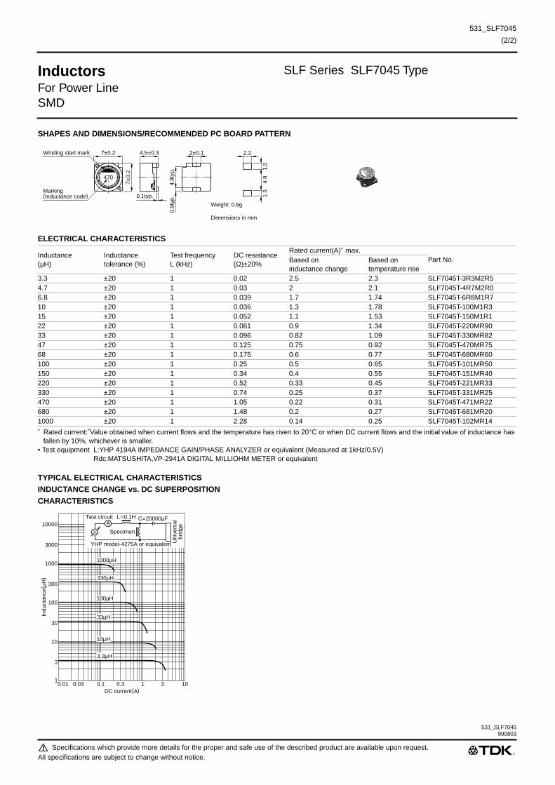
531_SLF7045
(2/2)
531_SLF7045
Inductors SLF Series SLF7045 Type
For Power LineSMD
SHAPES AND DIMENSIONS/RECOMMENDED PC BOARD PATTERN
ELECTRICAL CHARACTERISTICS
∗ Rated current: Value obtained when current flows and the temperature has risen to 20°C or when DC current flows and the initial value of inductance has fallen by 10%, whichever is smaller.
• Test equipment L:YHP 4194A IMPEDANCE GAIN/PHASE ANALYZER or equivalent (Measured at 1kHz/0.5V)Rdc:MATSUSHITA,VP-2941A DIGITAL MILLIOHM METER or equivalent
TYPICAL ELECTRICAL CHARACTERISTICSINDUCTANCE CHANGE vs. DC SUPERPOSITIONCHARACTERISTICS
Inductance(µH)
Inductancetolerance (%)
Test frequency L (kHz)
DC resistance(Ω)±20%
Rated current(A)∗ max.Part No.Based on
inductance changeBased ontemperature rise
3.3 ±20 1 0.02 2.5 2.3 SLF7045T-3R3M2R54.7 ±20 1 0.03 2 2.1 SLF7045T-4R7M2R06.8 ±20 1 0.039 1.7 1.74 SLF7045T-6R8M1R710 ±20 1 0.036 1.3 1.78 SLF7045T-100M1R315 ±20 1 0.052 1.1 1.53 SLF7045T-150M1R122 ±20 1 0.061 0.9 1.34 SLF7045T-220MR9033 ±20 1 0.096 0.82 1.09 SLF7045T-330MR8247 ±20 1 0.125 0.75 0.92 SLF7045T-470MR7568 ±20 1 0.175 0.6 0.77 SLF7045T-680MR60100 ±20 1 0.25 0.5 0.65 SLF7045T-101MR50150 ±20 1 0.34 0.4 0.55 SLF7045T-151MR40220 ±20 1 0.52 0.33 0.45 SLF7045T-221MR33330 ±20 1 0.74 0.25 0.37 SLF7045T-331MR25470 ±20 1 1.05 0.22 0.31 SLF7045T-471MR22680 ±20 1 1.48 0.2 0.27 SLF7045T-681MR201000 ±20 1 2.28 0.14 0.25 SLF7045T-102MR14
7±0.2Winding start mark
Marking(Inductance code)
7±0.
2
4.5±0.3
0.1typ.
4704.
9typ
.0.
9typ
.
Weight: 0.6g
Dimensions in mm
2±0.1
4.9
1.5
1.5
2.2
DC current(A)0.01
3
1
100
1000
300
30
10
10000
3000
0.1 0.30.03 31 10
Indu
ctan
ce( µ
H)
AL=0.1H C=20000µF
Specimen
Test circuit
YHP model-4275A or equivalent
DC
Uni
vers
albr
idge
1000µH
330µH
100µH
33µH
10µH
3.3µH
990803
Specifications which provide more details for the proper and safe use of the described product are available upon request.All specifications are subject to change without notice.

Inductors ELC Series ELC0607 Type
For Power LineRadial
FEATURES• The ELC series feature low DC resistance and high current han-
dling capacities, making them ideal for power supply applica-
tions.
• Epoxy resin construction assures high reliability.
• Available in tape packaging to support automated mounting
machines.
APPLICATIONSTelevisions, VCRs, personal computers, and other electronic
equipment.
SPECIFICATIONS
PRODUCT IDENTIFICATION
(1)Series name
(2)Dimensions
(3)Packaging style (Taping products are standard.)
(4)Inductance value
(5)Inductance tolerance
(6)Rated current
PACKAGING STYLE AND QUANTITIES
Operating temperature range–20 to +80°C [Including self-temperature rise]
Storage temperature range –40 to +80°C [Unit of products]Terminal tensile strength 14.7N min.
0607 7.4×6.2×10mm (lead pitch 5mm)
RA Taping (ammo-pack)SKI Bulk
1R0 1µH120 12µH
J ±5%K ±10%
3R0 3AR92 0.92A
Packaging style QuantityTaping(Ammo-pack) 2000 pieces/boxBulk 1000 pieces/pack
ELC 0607 RA- 1R0 J 3R0
(1) (2) (3) (4) (5) (6)
Specifications which provide more details for the proper and safe use of the described product are available upon request.All specifications are subject to change without notice.

Inductors ELC Series ELC0607 Type
For Power LineRadial
SHAPES AND DIMENSIONSBULK AMMO-PACK TAPING STYLE CHARACTERISTICS
ELECTRICAL CHARACTERISTICS
∗ 1 X: Please specify packaging style, SKI(Bulk) or RA(Taping).∗ 2 X: Please specify inductance tolerance, K(±10%) or J(±5%)• Test equipment Inductance, Q: YHP4194A IMPEDANCE/GAIN-PHASE ANALYZER
DC resistante: MATSUSHITA VP-2941A DIGITAL MILLIOHM METER
10m
ax.
(2.5)
6.2max.
ø0.62+0.03, –0.05
7.4+0.6
5+1, –0.8
4.5
+1.
5, –
0.5
10m
ax.
(2.5)
27.5
max
.
5+0.6, –0.2
Dimensions in mm
6.2max.
ø0.62+0.03, –0.05
7.4+0.6 Operating temperature range
–20 to +80°C [Including self-temperature rise, 20°C max.]
Storage temperaturerange
–40 to +80°C
Rated current Based on temperature rise, 20°CTerminal tensile strength
14.7N min.
Moisture resistance ∆L/L ±5% ∆Q/Q ±25%
Inductance(µH)
Inductancetolerance
Q ref.Test frequencyL, Q(MHz)
DC resistance(Ω)max.
Rated current(A)max.
Part No.
1 ±10, ±5% 10 7.96 0.026 3 ELC0607X∗ 1-1R0X∗ 23R01.2 ±10, ±5% 10 7.96 0.029 2.8 ELC0607X-1R2X2R81.5 ±10, ±5% 10 7.96 0.031 2.8 ELC0607X-1R5X2R81.8 ±10, ±5% 10 7.96 0.035 2.6 ELC0607X-1R8X2R62.2 ±10, ±5% 10 7.96 0.039 2.5 ELC0607X-2R2X2R52.7 ±10, ±5% 10 7.96 0.041 2.3 ELC0607X-2R7X2R33.3 ±10, ±5% 10 7.96 0.044 2.2 ELC0607X-3R3X2R23.9 ±10, ±5% 10 7.96 0.05 2.1 ELC0607X-3R9X2R14.7 ±10, ±5% 10 7.96 0.052 2 ELC0607X-4R7X2R05.6 ±10, ±5% 10 7.96 0.062 1.9 ELC0607X-5R6X1R96.8 ±10, ±5% 10 7.96 0.066 1.8 ELC0607X-6R8X1R88.2 ±10, ±5% 10 7.96 0.08 1.7 ELC0607X-8R2X1R710 ±10, ±5% 20 2.52 0.09 1.6 ELC0607X-100X1R612 ±10, ±5% 20 2.52 0.1 1.5 ELC0607X-120X1R515 ±10, ±5% 20 2.52 0.12 1.3 ELC0607X-150X1R318 ±10, ±5% 20 2.52 0.145 1.2 ELC0607X-180X1R222 ±10, ±5% 20 2.52 0.18 1.2 ELC0607X-220X1R227 ±10, ±5% 20 2.52 0.22 1 ELC0607X-270X1R033 ±10, ±5% 20 2.52 0.25 0.92 ELC0607X-330XR9239 ±10, ±5% 20 2.52 0.31 0.88 ELC0607X-390XR8847 ±10, ±5% 20 2.52 0.35 0.77 ELC0607X-470XR7756 ±10, ±5% 20 2.52 0.42 0.72 ELC0607X-560XR7268 ±10, ±5% 20 2.52 0.45 0.63 ELC0607X-680XR6382 ±10, ±5% 20 2.52 0.57 0.61 ELC0607X-820XR61100 ±10, ±5% 20 0.796 0.69 0.55 ELC0607X-101XR55150 ±10, ±5% 30 0.796 1.1 0.44 ELC0607X-151XR44220 ±10, ±5% 40 0.796 1.7 0.36 ELC0607X-221XR36330 ±10, ±5% 50 0.796 2.5 0.29 ELC0607X-331XR29470 ±10, ±5% 60 0.796 4.1 0.23 ELC0607X-471XR23
Specifications which provide more details for the proper and safe use of the described product are available upon request.All specifications are subject to change without notice.

532_ELC0607
Inductors ELC Series ELC0607 Type
For Power LineRadial
TYPICAL ELECTRICAL CHARACTERISTICSINDUCTANCE CHANGE vs. DC SUPERPOSITION ATTENUATION vs. FREQUENCY CHARACTERISTICSCHARACTERISTICS
1000
100
10
1
0.10.01 0.03 0.1 0.3 1 5 10
Indu
ctan
ce( µ
H)
DC current(A)
470µH
100µH
10µH
1µH
Frequency(MHz)
–1000.3 1 3 10 30 100 300 1000
Atte
nuat
ion
( dB
)
–90
–80
–70
–60
–50
–40
–30
–20
–10
0
1µH
10µH
470µH100µH
990715
Specifications which provide more details for the proper and safe use of the described product are available upon request.All specifications are subject to change without notice.

Inductors SL Series SL1215 Type
For Power LineRadial
FEATURES• This is a low Rdc, best for the power supply line.
• There is a series of many types from low inductance to high
inductance in large current.
APPLICATIONSTelevisions, CRT displays, printers, and various types of electronic
products.
SPECIFICATIONS
∗ Only for lead type specification. Wire type’s specification depends on the vibration test.
PRODUCT IDENTIFICATION
(1)Series name
(2)Dimensions
(3)Inductance value
(4)Inductance tolerance
(5)Rated current
PACKAGING STYLE AND QUANTITIES
Operating temperature range–40 to +85°C [Including self-temperature rise]
Storage temperature range –40 to +85°C [Unit of products] Terminal strength 9.8N min.∗
Type Dimension Lead pitch
1215 ø12×14.5mm11mm (10 to 100µH for wire type)7.5mm (150 to 5600µH for lead type)
1720 ø16.9×20.5mm 10mm (lead type)1923 ø18.8×23.5mm 10mm (lead type)2125 ø20.8×25.5mm 10mm (lead type)
100 10µH102 1000µH
K ±10%
3R6 3.6AR20 0.2A
Packaging style Type QuantityBulk SL1215 100 pieces/tray
SL1720 100 pieces/traySL1923 100 pieces/traySL2125 100 pieces/tray
SL 1215 - 100 K 3R6
(1) (2) (3) (4) (5)
Specifications which provide more details for the proper and safe use of the described product are available upon request.All specifications are subject to change without notice.

532_SL1215980917
Inductors SL Series SL1215 Type
For Power LineRadial
SHAPES AND DIMENSIONSWIRE TYPE (10 to 100µH) LEAD TYPE (150 to 5600µH)
ELECTRICAL CHARACTERISTICS
∗ Rated current: Value obtained when current flows and self-temperature has risen to 25°C.• Test equipment Inductance:LCR METER YHP4261A, or equivalent
Rdc: MILLIOHM METER VP-2941A MATSUSHITA, or equivalent
TYPICAL ELECTRICAL CHARACTERISTICS INDUCTANCE CHANGE vs. DC SUPERPOSITION CHARACTERISTICS
Inductance(µH)
Inductancetolerance
DC resistance(Ω)max.
Rated current(A)∗ max.Part No. Lead wire styleBased on inductance
changeBased on temperature rise
10 ±10% 0.019 9.8 3.6 SL1215-100K3R6 Wire type15 ±10% 0.022 8.9 3.3 SL1215-150K3R3 Wire type22 ±10% 0.031 7.2 2.8 SL1215-220K2R8 Wire type33 ±10% 0.044 6 2.3 SL1215-330K2R3 Wire type47 ±10% 0.059 4.9 2 SL1215-470K2R0 Wire type68 ±10% 0.073 4.2 1.8 SL1215-680K1R8 Wire type100 ±10% 0.1 3.4 1.5 SL1215-101K1R5 Wire type150 ±10% 0.15 2.8 1.3 SL1215-151K1R3 Lead type220 ±10% 0.26 1.9 1 SL1215-221K1R0 Lead type330 ±10% 0.32 1.8 0.91 SL1215-331KR91 Lead type470 ±10% 0.48 1.6 0.72 SL1215-471KR72 Lead type680 ±10% 0.73 1.3 0.58 SL1215-681KR58 Lead type1000 ±10% 0.96 1.1 0.51 SL1215-102KR51 Lead type1500 ±10% 1.4 0.9 0.42 SL1215-152KR42 Lead type2200 ±10% 2.5 0.7 0.31 SL1215-222KR31 Lead type3300 ±10% 3.3 0.6 0.27 SL1215-332KR27 Lead type5600 ±10% 6.4 0.47 0.2 SL1215-562KR20 Lead type
14.5
±0.5
5±1
( 0.5
max
.)
Dim
ensi
ons
in b
efor
e so
lder
ing
ø12±0.5Winding startmark
11typ.
Solderingø0.6 to 0.8 ø0.8±0.05
14.5
±0.5
5±1
ø12±0.5Winding startmark
7.5±0.8
Weight: 7g typ.
Dimensions in mm
DC current(A)0.1 1 30.3 3010 100
10
3
1
100
1000
300
10000
30
3000
Indu
ctan
ce( µ
H)
1000µH
470µH
220µH
100µH
47µH
22µH
10µH
2200µH
AL=0.1H C=20000µFTest circuit
DC
Uni
vers
albr
idgeSpecimen
YHP model-4261Aor equivalent
Specifications which provide more details for the proper and safe use of the described product are available upon request.All specifications are subject to change without notice.

Inductors SL Series SL1720 Type
For Power LineRadial
FEATURES• This is a low Rdc, best for the power supply line.
• There is a series of many types from low inductance to high
inductance in large current.
APPLICATIONSTelevisions, CRT displays, printers, and various types of electronic
products.
SPECIFICATIONS
∗ Only for lead type specification. Wire type’s specification depends on the vibration test.
PRODUCT IDENTIFICATION
(1)Series name
(2)Dimensions
(3)Inductance value
(4)Inductance tolerance
(5)Rated current
PACKAGING STYLE AND QUANTITIES
Operating temperature range–40 to +85°C [Including self-temperature rise]
Storage temperature range –40 to +85°C [Unit of products] erminal strength 9.8N min.∗
Type Dimension Lead pitch
1215 ø12×14.5mm11mm (10 to 100µH for wire type)7.5mm (150 to 5600µH for lead type)
1720 ø16.9×20.5mm 10mm (lead type)1923 ø18.8×23.5mm 10mm (lead type)2125 ø20.8×25.5mm 10mm (lead type)
100 10µH102 1000µH
K ±10%
3R6 3.6AR20 0.2A
Packaging style Type QuantityBulk SL1215 100 pieces/tray
SL1720 100 pieces/traySL1923 100 pieces/traySL2125 100 pieces/tray
SL 1215 - 100 K 3R6
(1) (2) (3) (4) (5)
Specifications which provide more details for the proper and safe use of the described product are available upon request.All specifications are subject to change without notice.

532_SL1720
Inductors SL Series SL1720 Type
For Power LineRadial
SHAPES AND DIMENSIONS
ELECTRICAL CHARACTERISTICS
∗ Rated current: Value obtained when current flows and self-temperature has risen to 25°C.• Test equipment Inductance:LCR METER YHP4261A, or equivalent
Rdc: MILLIOHM METER VP-2941A MATSUSHITA, or equivalent
TYPICAL ELECTRICAL CHARACTERISTICS INDUCTANCE CHANGE vs. DC SUPERPOSITION CHARACTERISTICS
Inductance(µH)
Inductancetolerance
DC resistance(Ω)max.
Rated current(A)∗ max.Part No.Based on inductance
changeBased ontemperature rise
150 ±10% 0.1 3 2.1 SL1720-151K2R1220 ±10% 0.13 2.6 1.8 SL1720-221K1R8330 ±10% 0.18 2 1.5 SL1720-331K1R5470 ±10% 0.27 1.7 1.3 SL1720-471K1R3680 ±10% 0.38 1.4 1 SL1720-681K1R01000 ±10% 0.54 1.1 0.9 SL1720-102KR901500 ±10% 0.86 0.98 0.72 SL1720-152KR722200 ±10% 1.22 0.81 0.6 SL1720-222KR60
ø16.9±0.5Winding startmark
20.5
±0.5
5±1
10±1
ø1Winding startside
Weight: 13g typ.
Dimensions in mm
DC current(A)0.01 0.1 0.30.03 31 10
10
100
1000
300
30
10000
3000
Indu
ctan
ce( µ
H)
2200µH
1500µH1000µH
680µH
470µH
330µH
220µH
150µH
AL=0.1H C=20000µFTest circuit
DC
Uni
vers
albr
idgeSpecimen
YHP model-4261Aor equivalent
980917
Specifications which provide more details for the proper and safe use of the described product are available upon request.All specifications are subject to change without notice.

Inductors SL Series SL1923 Type
For Power LineRadial
FEATURES• This is a low Rdc, best for the power supply line.
• There is a series of many types from low inductance to high
inductance in large current.
APPLICATIONSTelevisions, CRT displays, printers, and various types of electronic
products.
SPECIFICATIONS
∗ Only for lead type specification. Wire type’s specification depends on the vibration test.
PRODUCT IDENTIFICATION
(1)Series name
(2)Dimensions
(3)Inductance value
(4)Inductance tolerance
(5)Rated current
PACKAGING STYLE AND QUANTITIES
Operating temperature range–40 to +85°C [Including self-temperature rise]
Storage temperature range –40 to +85°C [Unit of products] Terminal strength 9.8N min.∗
Type Dimension Lead pitch
1215 ø12×14.5mm11mm (10 to 100µH for wire type)7.5mm (150 to 5600µH for lead type)
1720 ø16.9×20.5mm 10mm (lead type)1923 ø18.8×23.5mm 10mm (lead type)2125 ø20.8×25.5mm 10mm (lead type)
100 10µH102 1000µH
K ±10%
3R6 3.6AR20 0.2A
Packaging style Type QuantityBulk SL1215 100 pieces/tray
SL1720 100 pieces/traySL1923 100 pieces/traySL2125 100 pieces/tray
SL 1215 - 100 K 3R6
(1) (2) (3) (4) (5)
Specifications which provide more details for the proper and safe use of the described product are available upon request.All specifications are subject to change without notice.

532_SL1923
Inductors SL Series SL1923 Type
For Power LineRadial
SHAPES AND DIMENSIONS
ELECTRICAL CHARACTERISTICS
∗ Rated current: Value obtained when current flows and self-temperature has risen to 25°C.• Test equipment Inductance:LCR METER YHP4261A, or equivalent
Rdc: MILLIOHM METER VP-2941A MATSUSHITA, or equivalent
TYPICAL ELECTRICAL CHARACTERISTICS INDUCTANCE CHANGE vs. DC SUPERPOSITION CHARACTERISTICS
Inductance(µH)
Inductancetolerance
DC resistance(Ω)max.
Rated current(A)∗ max.Part No.Based on inductance
changeBased ontemperature rise
470 ±10% 0.2 2.1 1.5 SL1923-471K1R5680 ±10% 0.29 1.8 1.3 SL1923-681K1R31000 ±10% 0.41 1.4 1.1 SL1923-102K1R12200 ±10% 1 1 0.7 SL1923-222KR7010000 ±10% 4.3 0.46 0.33 SL1923-103KR3315000 ±10% 7.1 0.38 0.26 SL1923-153KR26
ø18.8±0.5Winding startmark
23.5
±0.5
5±1
10±1
ø1Weight: 19g typ.
Dimensions in mm
Winding startside
DC current(A)0.01 0.1 0.30.03 31 10
100
1000
10000
3000
300
100000
30000
Indu
ctan
ce( µ
H)
15000µH
10000µH
2200µH
1000µH
680µH
470µH
AL=0.1H C=20000µFTest circuit
DC
Uni
vers
albr
idgeSpecimen
YHP model-4261Aor equivalent
980917
Specifications which provide more details for the proper and safe use of the described product are available upon request.All specifications are subject to change without notice.

Inductors SL Series SL2125 Type
For Power LineRadial
FEATURES• This is a low Rdc, best for the power supply line.
• There is a series of many types from low inductance to high
inductance in large current.
APPLICATIONSTelevisions, CRT displays, printers, and various types of electronic
products.
SPECIFICATIONS
∗ Only for lead type specification. Wire type’s specification depends on the vibration test.
PRODUCT IDENTIFICATION
(1)Series name
(2)Dimensions
(3)Inductance value
(4)Inductance tolerance
(5)Rated current
PACKAGING STYLE AND QUANTITIES
Operating temperature range–40 to +85°C [Including self-temperature rise]
Storage temperature range –40 to +85°C [Unit of products] Terminal strength 9.8N min.∗
Type Dimension Lead pitch
1215 ø12×14.5mm11mm (10 to 100µH for wire type)7.5mm (150 to 5600µH for lead type)
1720 ø16.9×20.5mm 10mm (lead type)1923 ø18.8×23.5mm 10mm (lead type)2125 ø20.8×25.5mm 10mm (lead type)
100 10µH102 1000µH
K ±10%
3R6 3.6AR20 0.2A
Packaging style Type QuantityBulk SL1215 100 pieces/tray
SL1720 100 pieces/traySL1923 100 pieces/traySL2125 100 pieces/tray
SL 1215 - 100 K 3R6
(1) (2) (3) (4) (5)
Specifications which provide more details for the proper and safe use of the described product are available upon request.All specifications are subject to change without notice.

532_SL2125
Inductors SL Series SL2125 Type
For Power LineRadial
SHAPES AND DIMENSIONS
ELECTRICAL CHARACTERISTICS
∗ Rated current: Value obtained when current flows and self-temperature has risen to 25°C.• Test equipment Inductance: LCR METER YHP4261A, or equivalent
Rdc: MILLIOHM METER VP-2941A MATSUSHITA, or equivalent
TYPICAL ELECTRICAL CHARACTERISTICS INDUCTANCE CHANGE vs. DC SUPERPOSITION CHARACTERISTICS
Inductance(µH)
Inductancetolerance
Testfrequency L(kHz)
DC resistance(Ω)max.
Rated current(A)∗ max.Part No.Based on inductance
changeBased ontemperature rise
1000 ±10% 1 0.35 1.7 1.3 SL2125-102K1R31500 ±10% 1 0.61 1.3 0.99 SL2125-152KR992200 ±10% 1 0.78 1.1 0.87 SL2125-222KR873300 ±10% 1 1.15 0.95 0.72 SL2125-332KR724700 ±10% 1 1.71 0.78 0.59 SL2125-472KR596800 ±10% 1 2.61 0.66 0.47 SL2125-682KR4710000 ±10% 1 3.41 0.55 0.41 SL2125-103KR41
25.5
±0.5
5±1
10±1
ø1
ø20.8±0.5Winding startmark
Winding startside
Weight: 24g typ.
Dimensions in mm
DC current(A)0.1 10.3 3 10
100
1000
10000
3000
300
100000
30000
Indu
ctan
ce( µ
H)
10000µH
6800µH
3300µH
2200µH
1500µH
1000µH
4700µH
AL=0.1H C=20000µFTest circuit
DC
Uni
vers
albr
idgeSpecimen
YHP model-4261Aor equivalent
980917
Specifications which provide more details for the proper and safe use of the described product are available upon request.All specifications are subject to change without notice.

Inductors TSL Series TSL0709 Type
For Power LineRadial
FEATURES• The TSL series feature low DC resistance and high current han-
dling capacities, making them ideal for power supply line appli-
cations.
• These parts are manufactured to a high degree of dimensional
accuracy using non-flammable material (UL94V-0).
• Available in tape packaging to support automated mounting
machines.
APPLICATIONSTelevisions, VCRs, personal computers, and other electronic
equipments.
SPECIFICATIONS
PRODUCT IDENTIFICATION
(1)Series name
(2)Dimensions
(3)Packaging style
(4)Inductance value
(5)Inductance tolerance
(6)Rated current
PACKAGING STYLE AND QUANTITIES
∗ 50 pieces/tray
Operating temperature range–20 to +85°C[Including self-temperature rise]
Storage temperature range –40 to +85°C[Unit of products]Terminal tensile strength 9.8N min.
0709 ø7.7×9.5mm (lead pitch 5mm)0809 ø8.8×9.5mm (lead pitch 5mm)1112 ø11.2×12.2mm (lead pitch 5mm)1315 ø14×17mm (lead pitch 7.5mm)
RA Taping(Ammo-pack)S Bulk
1R0 1µH100 10µH
J ±5%K ±10%M ±20%
5R0 5AR66 0.66A
Packaging style Type QuantityTaping(Ammo-pack)
TSL0709RA 1000 pieces/boxTSL0809RA 500 pieces/boxTSL1112RA 500 pieces/boxTSL1315RA 200 pieces/box
Bulk TSL0709S 500 pieces/10tray∗
TSL0809S 500 pieces/10trayTSL1112S 400 pieces/8trayTSL1315S 50 pieces/pack
TSL 0709 RA- 1R0 M 5R0
(1) (2) (3) (4) (5) (6)
Specifications which provide more details for the proper and safe use of the described product are available upon request.All specifications are subject to change without notice.

532_TSL0709980917
Inductors TSL Series TSL0709 Type
For Power LineRadial
SHAPES AND DIMENSIONS
ELECTRICAL CHARACTERISTICS
∗ Rated current: Value obtained when current flows and the temperature has risen to 25°C or when DC current flows and the initial value of inductance has fallen by 20%, whichever is smaller.
TYPICAL ELECTRICAL CHARACTERISTICSINDUCTANCE CHANGE vs. DC SUPERPOSITIONCHARACTERISTICS
5+2, –1
9.5
±0.1
ø7.
7±0.
35
±1ø0.65±0.05
Weight: 1.1g
Dimensions in mm
Inductance(µH)
Inductancetolerance
Q min.Test frequencyL/Q (Hz)
Self-resonantfrequency(MHz)min.
DC resistance(Ω)max.
Rated current(A)∗ max.Part No.Based on inductance
changeBased ontemperature rise
1 ±20% 10 1k/7.96M 70 0.006 6.6 5 TSL0709-1R0M5R01.5 ±20% 10 1k/7.96M 56 0.008 5.4 4.3 TSL0709-1R5M4R32.2 ±20% 10 1k/7.96M 45 0.011 4 3.7 TSL0709-2R2M3R73.3 ±20% 10 1k/7.96M 36 0.018 3.6 2.9 TSL0709-3R3M2R94.7 ±20% 10 1k/7.96M 29 0.022 3.1 2.6 TSL0709-4R7M2R66.8 ±20% 10 1k/7.96M 24 0.028 2.5 2.3 TSL0709-6R8M2R310 ±10% 20 1k/2.52M 19 0.043 2.1 1.9 TSL0709-100K1R915 ±10% 20 1k/2.52M 15 0.056 1.7 1.6 TSL0709-150K1R622 ±10% 20 1k/2.52M 12 0.086 1.4 1.3 TSL0709-220K1R333 ±10% 20 1k/2.52M 9.4 0.14 1.1 1 TSL0709-330K1R047 ±10% 20 1k/2.52M 7.6 0.17 0.96 0.94 TSL0709-470KR9468 ±10% 20 1k/2.52M 6.2 0.28 0.79 0.73 TSL0709-680KR73100 ±10% 20 1k/796k 5 0.33 0.66 0.67 TSL0709-101KR66150 ±10% 20 1k/796k 4 0.56 0.53 0.52 TSL0709-151KR52220 ±10% 20 1k/796k 3.2 0.72 0.44 0.46 TSL0709-221KR44330 ±10% 20 1k/796k 2.5 1.1 0.36 0.37 TSL0709-331KR36470 ±10% 20 1k/796k 2 1.7 0.3 0.3 TSL0709-471KR30680 ±10% 20 1k/796k 1.7 2.3 0.25 0.26 TSL0709-681KR251000 ±10% 70 1k/252k 1.3 4.3 0.2 0.19 TSL0709-102KR191500 ±10% 50 1k/252k 1.3 5 0.17 0.16 TSL0709-152KR16
DC current(A)0.01
0.1
3
1
0.3
100
1000
300
30
10
10000
3000
0.1 0.30.03 31 10
Indu
ctan
ce( µ
H)
1000µH
330µH
100µH
33µH
10µH
3.3µH
1µH
AL=0.1H C=20000µFTest circuit
DC
Uni
vers
albr
idgeSpecimen
YHP model-4275Aor equivalent
Specifications which provide more details for the proper and safe use of the described product are available upon request.All specifications are subject to change without notice.

Inductors TSL Series TSL1112 Type
For Power LineRadial
FEATURES• The TSL series feature low DC resistance and high current han-
dling capacities, making them ideal for power supply line appli-
cations.
• These parts are manufactured to a high degree of dimensional
accuracy using non-flammable material (UL94V-0).
• Available in tape packaging to support automated mounting
machines.
APPLICATIONSTelevisions, VCRs, personal computers, and other electronic
equipments.
SPECIFICATIONS
PRODUCT IDENTIFICATION
(1)Series name
(2)Dimensions
(3)Packaging style
(4)Inductance value
(5)Inductance tolerance
(6)Rated current
PACKAGING STYLE AND QUANTITIES
∗ 50 pieces/tray
Operating temperature range–20 to +85°C[Including self-temperature rise]
Storage temperature range –40 to +85°C[Unit of products]Terminal tensile strength 9.8N min.
0709 ø7.7×9.5mm (lead pitch 5mm)0809 ø8.8×9.5mm (lead pitch 5mm)1112 ø11.2×12.2mm (lead pitch 5mm)1315 ø14×17mm (lead pitch 7.5mm)
RA Taping(Ammo-pack)S Bulk
1R0 1µH100 10µH
J ±5%K ±10%M ±20%
5R0 5AR66 0.66A
Packaging style Type QuantityTaping(Ammo-pack)
TSL0709RA 1000 pieces/boxTSL0809RA 500 pieces/boxTSL1112RA 500 pieces/boxTSL1315RA 200 pieces/box
Bulk TSL0709S 500 pieces/10tray∗
TSL0809S 500 pieces/10trayTSL1112S 400 pieces/8trayTSL1315S 50 pieces/pack
TSL 0709 RA- 1R0 M 5R0
(1) (2) (3) (4) (5) (6)
Specifications which provide more details for the proper and safe use of the described product are available upon request.All specifications are subject to change without notice.
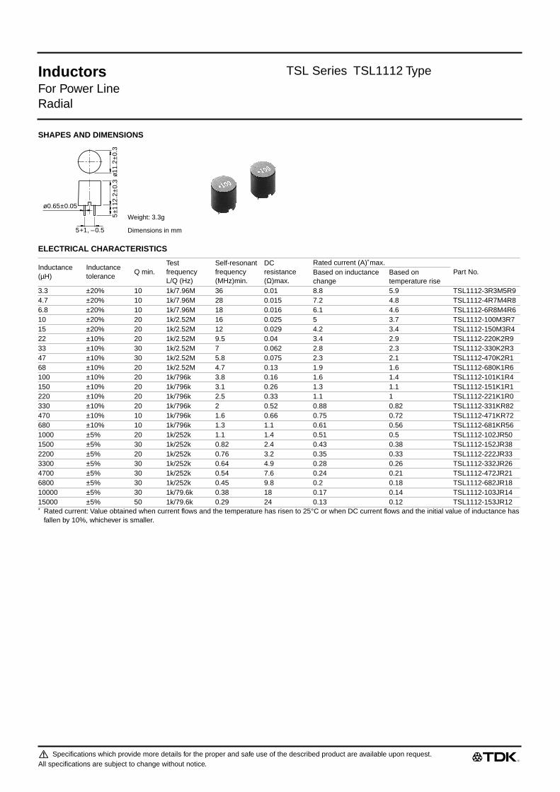
Inductors TSL Series TSL1112 Type
For Power LineRadial
SHAPES AND DIMENSIONS
ELECTRICAL CHARACTERISTICS
∗ Rated current: Value obtained when current flows and the temperature has risen to 25°C or when DC current flows and the initial value of inductance has fallen by 10%, whichever is smaller.
12.2
±0.3
5±1
5+1, –0.5
ø0.65±0.05
Weight: 3.3g
Dimensions in mm
ø11.
2±0
.3
Inductance(µH)
Inductancetolerance
Q min.Test frequencyL/Q (Hz)
Self-resonantfrequency(MHz)min.
DC resistance(Ω)max.
Rated current (A)∗ max.Part No.Based on inductance
changeBased ontemperature rise
3.3 ±20% 10 1k/7.96M 36 0.01 8.8 5.9 TSL1112-3R3M5R94.7 ±20% 10 1k/7.96M 28 0.015 7.2 4.8 TSL1112-4R7M4R86.8 ±20% 10 1k/7.96M 18 0.016 6.1 4.6 TSL1112-6R8M4R610 ±20% 20 1k/2.52M 16 0.025 5 3.7 TSL1112-100M3R715 ±20% 20 1k/2.52M 12 0.029 4.2 3.4 TSL1112-150M3R422 ±10% 20 1k/2.52M 9.5 0.04 3.4 2.9 TSL1112-220K2R933 ±10% 30 1k/2.52M 7 0.062 2.8 2.3 TSL1112-330K2R347 ±10% 30 1k/2.52M 5.8 0.075 2.3 2.1 TSL1112-470K2R168 ±10% 20 1k/2.52M 4.7 0.13 1.9 1.6 TSL1112-680K1R6100 ±10% 20 1k/796k 3.8 0.16 1.6 1.4 TSL1112-101K1R4150 ±10% 20 1k/796k 3.1 0.26 1.3 1.1 TSL1112-151K1R1220 ±10% 20 1k/796k 2.5 0.33 1.1 1 TSL1112-221K1R0330 ±10% 20 1k/796k 2 0.52 0.88 0.82 TSL1112-331KR82470 ±10% 10 1k/796k 1.6 0.66 0.75 0.72 TSL1112-471KR72680 ±10% 10 1k/796k 1.3 1.1 0.61 0.56 TSL1112-681KR561000 ±5% 20 1k/252k 1.1 1.4 0.51 0.5 TSL1112-102JR501500 ±5% 30 1k/252k 0.82 2.4 0.43 0.38 TSL1112-152JR382200 ±5% 20 1k/252k 0.76 3.2 0.35 0.33 TSL1112-222JR333300 ±5% 30 1k/252k 0.64 4.9 0.28 0.26 TSL1112-332JR264700 ±5% 30 1k/252k 0.54 7.6 0.24 0.21 TSL1112-472JR216800 ±5% 30 1k/252k 0.45 9.8 0.2 0.18 TSL1112-682JR1810000 ±5% 30 1k/79.6k 0.38 18 0.17 0.14 TSL1112-103JR1415000 ±5% 50 1k/79.6k 0.29 24 0.13 0.12 TSL1112-153JR12
Specifications which provide more details for the proper and safe use of the described product are available upon request.All specifications are subject to change without notice.

532_TSL1112
Inductors TSL Series TSL1112 Type
For Power LineRadial
TYPICAL ELECTRICAL CHARACTERISTICSINDUCTANCE CHANGE vs. DC SUPERPOSITIONCHARACTERISTICS
DC current(A)0.01 0.1 0.30.03 31 10
10
3
1
100
1000
300
30
10000
3000
Indu
ctan
ce( µ
H)
1000µH
330µH
33µH
10µH
3.3µH
100µH
10000µH
3300µH AL=0.1HC=20000µF
Test circuit
DC
Universal bridge
Specimen
YHP model-4255Aor equivalent
980917
Specifications which provide more details for the proper and safe use of the described product are available upon request.All specifications are subject to change without notice.
Inductors TSL Series TSL1315 Type
For Power LineRadial
FEATURES• The TSL series feature low DC resistance and high current han-
dling capacities, making them ideal for power supply line appli-
cations.
• These parts are manufactured to a high degree of dimensional
accuracy using non-flammable material (UL94V-0).
• Available in tape packaging to support automated mounting
machines.
APPLICATIONSTelevisions, VCRs, personal computers, and other electronic
equipments.
SPECIFICATIONS
PRODUCT IDENTIFICATION
(1)Series name
(2)Dimensions
(3)Packaging style
(4)Inductance value
(5)Inductance tolerance
(6)Rated current
PACKAGING STYLE AND QUANTITIES
∗ 50 pieces/tray
Operating temperature range–20 to +85°C[Including self-temperature rise]
Storage temperature range –40 to +85°C[Unit of products]Terminal tensile strength 9.8N min.
0709 ø7.7×9.5mm (lead pitch 5mm)0809 ø8.8×9.5mm (lead pitch 5mm)1112 ø11.2×12.2mm (lead pitch 5mm)1315 ø14×17mm (lead pitch 7.5mm)
RA Taping(Ammo-pack)S Bulk
1R0 1µH100 10µH
J ±5%K ±10%M ±20%
5R0 5AR66 0.66A
Packaging style Type QuantityTaping(Ammo-pack)
TSL0709RA 1000 pieces/boxTSL0809RA 500 pieces/boxTSL1112RA 500 pieces/boxTSL1315RA 200 pieces/box
Bulk TSL0709S 500 pieces/10tray∗
TSL0809S 500 pieces/10trayTSL1112S 400 pieces/8trayTSL1315S 50 pieces/pack
TSL 0709 RA- 1R0 M 5R0
(1) (2) (3) (4) (5) (6)
Specifications which provide more details for the proper and safe use of the described product are available upon request.All specifications are subject to change without notice.

532_TSL1315
Inductors TSL Series TSL1315 Type
For Power LineRadial
SHAPES AND DIMENSIONS
ELECTRICAL CHARACTERISTICS
∗ Rated current: Value obtained when current flows and the temperature has risen to 25°C or when DC current flows and the initial value of inductance has fallen by 10%, whichever is smaller.
TYPICAL ELECTRICAL CHARACTERISTICSINDUCTANCE CHANGE vs. DC SUPERPOSITIONCHARACTERISTICS
ø14
max
.17
max
.5
±0.5
7.5±0.5
ø0.8±0.05Weight: 7.5g
Dimensions in mm
Inductance(µH)
Inductancetolerance
Q min.Test frequencyL/Q (Hz)
Self-resonantfrequency(MHz)min.
DC resistance(Ω)max.
Rated current (A)∗ max.Part No.Based on inductance
changeBased ontemperature rise
10 ±10% 90 1k/2.52M 19 0.023 12 5.1 TSL1315-100K5R115 ±10% 90 1k/2.52M 12 0.028 9.5 4.5 TSL1315-150K4R522 ±10% 80 1k/2.52M 7.6 0.035 8.2 4.2 TSL1315-220K4R233 ±10% 70 1k/2.52M 6.9 0.043 6.8 3.7 TSL1315-330K3R747 ±10% 50 1k/2.52M 5.6 0.052 5.7 3.4 TSL1315-470K3R468 ±10% 40 1k/2.52M 4.4 0.068 4.8 3 TSL1315-680K3R0100 ±10% 50 1k/796k 3.3 0.097 3.9 2.5 TSL1315-101K2R5150 ±10% 50 1k/796k 2.6 0.14 3.2 2.1 TSL1315-151K2R1220 ±10% 40 1k/796k 2.2 0.2 2.7 1.7 TSL1315-221K1R7330 ±10% 30 1k/796k 1.8 0.3 2.1 1.4 TSL1315-331K1R4470 ±10% 30 1k/796k 1.5 0.43 1.8 1.1 TSL1315-471K1R1680 ±10% 30 1k/796k 1.2 0.61 1.5 0.99 TSL1315-681KR991000 ±5% 30 1k/252k 1 1 1.2 0.78 TSL1315-102JR781500 ±5% 40 1k/252k 0.83 1.3 1 0.68 TSL1315-152JR682200 ±5% 40 1k/252k 0.7 2 0.83 0.55 TSL1315-222JR553300 ±5% 40 1k/252k 0.6 3.1 0.69 0.44 TSL1315-332JR444700 ±5% 40 1k/252k 0.43 4.4 0.58 0.37 TSL1315-472JR376800 ±5% 30 1k/252k 0.38 6.5 0.46 0.3 TSL1315-682JR3010000 ±5% 70 1k/79.6k 0.3 10 0.4 0.24 TSL1315-103JR24
DC current(A)0.01 0.1 0.30.03 31 10
10
5
100
1000
300
30
10000
3000
100000
30000
Indu
ctan
ce( µ
H)
1000µH
330µH220µH
33µH47µH68µH
10µH
15µH
22µH
100µH150µH
3300µH
10000µH
AL=0.1H C=20000µFTest circuit
DC
LCR
met
er
Specimen
YHP model-4275Aor equivalent
980917
Specifications which provide more details for the proper and safe use of the described product are available upon request.All specifications are subject to change without notice.