DESIGN AND EVALUTION OF TWO CAVITY INJECTION MOULD FOR HANGER...
13
ISSN (PRINT): 2393-8374, (ONLINE): 2394-0697, VOLUME-4, ISSUE-5, 2017 87 DESIGN AND EVALUTION OF TWO CAVITY INJECTION MOULD FOR HANGER K. Divakara Murthy 1, Dr. P Jamaleswara Kumar 2, 1 Research scholor, 2 Associate Professor 1,2 Department Of Mechanical Engineering, KL University Abstract Tool Design is the process of designing and developing the tools, methods and techniques necessary to improve manufacturing efficiency and productivity. It gives industry the machine and special tooling needed for today high speed, high volume production. It does this at a level of quality and economy that will ensure that the cost of the product is competitive. Since no single tool or process can serve all the forms of manufacturing, tool designs an ever changing, growing process of creative problem solving. Plastic is a synthetic polymer of high molecular weight. It is composed of repeating organic chemical units. Polymer is a single large molecule. It I formed as a result of the union of two or more molecules of the simpler substances. Plastics did not enter our lives with the fanfare of other revolutionary inventions, but more by the process of infiltration. Plastic being the synthetic materials where at first considered to be cheap substitute for them better known and more expensive materials. Plastic articles are not only replacing wood, metal and other materials but because of their particular qualities. They function better than other materials for specific process. Through the year’s plastics have curved the right as material themselves and not as substitute for their materials. Not only are plastics more useful, adaptable and practical than the material. They have supplemented, but uses of plastics have been found for which no other material can be used. The plastics industry is one of the fastest growing major industries in the world. Every year there is an increase in the amount of plastics used in all types of products. These are emerging both as product innovations and as existing products converted from materials to plastics for competitive and economic advantage. These plastic components can be made by various molding processes, the process to be employed and the material to be used for the purpose entirely depends on the application of the component. Index Terms: AUTO-CAD, CATIA, Lathe Machine, CNC, Injection Moulding. I.INTRODUCTION The modern-day injection mould tool is often a complex arrangement of mechanical, electrical, pneumatic and hydraulic components expected to fulfill a range of demanding tasks. Whatever the complexity, the mould design must essentially specify a tool that will operate satisfactorily in production. To achieve this, it must meet the following prime objectives: It must operate at the required production rate or better and last at least for the predicted design life. It must be well designed and produce mouldings to the required specification. The design must specify a tool that will operate consistently and be reliable in production. It should not be prone to frequent breakdowns and should not require frequent maintenance or servicing. These objectives are not simple to achieve. At every cycle, the tool is clamped together under high loads and is subject to high injection pressures and high heat levels from the incoming polymer. During the cooling cycle, the moulding is cooled until it reaches ejection temperature, when the tool opens and the moulding is ejected.
Transcript of DESIGN AND EVALUTION OF TWO CAVITY INJECTION MOULD FOR HANGER...

ISSN (PRINT): 2393-8374, (ONLINE): 2394-0697, VOLUME-4, ISSUE-5, 2017
87
DESIGN AND EVALUTION OF TWO CAVITY INJECTION MOULD FOR HANGER
K. Divakara Murthy1, Dr. P Jamaleswara Kumar2,
1Research scholor,2Associate Professor 1,2 Department Of Mechanical Engineering, KL University
Abstract Tool Design is the process of designing and developing the tools, methods and techniques necessary to improve manufacturing efficiency and productivity. It gives industry the machine and special tooling needed for today high speed, high volume production. It does this at a level of quality and economy that will ensure that the cost of the product is competitive. Since no single tool or process can serve all the forms of manufacturing, tool designs an ever changing, growing process of creative problem solving. Plastic is a synthetic polymer of high molecular weight. It is composed of repeating organic chemical units. Polymer is a single large molecule. It I formed as a result of the union of two or more molecules of the simpler substances. Plastics did not enter our lives with the fanfare of other revolutionary inventions, but more by the process of infiltration. Plastic being the synthetic materials where at first considered to be cheap substitute for them better known and more expensive materials. Plastic articles are not only replacing wood, metal and other materials but because of their particular qualities. They function better than other materials for specific process. Through the year’s plastics have curved the right as material themselves and not as substitute for their materials. Not only are plastics more useful, adaptable and practical than the material. They have supplemented, but uses of plastics have been found for which no other material can be used. The plastics industry is one of the fastest growing major industries in the world. Every year there is an increase in the amount of plastics used in all types of products. These
are emerging both as product innovations and as existing products converted from materials to plastics for competitive and economic advantage. These plastic components can be made by various molding processes, the process to be employed and the material to be used for the purpose entirely depends on the application of the component. Index Terms: AUTO-CAD, CATIA, Lathe Machine, CNC, Injection Moulding.
I.INTRODUCTION The modern-day injection mould tool is often a complex arrangement of mechanical, electrical, pneumatic and hydraulic components expected to fulfill a range of demanding tasks. Whatever the complexity, the mould design must essentially specify a tool that will operate satisfactorily in production. To achieve this, it must meet the following prime objectives:
It must operate at the required production rate or better and last at least for the predicted design life.
It must be well designed and produce mouldings to the required specification.
The design must specify a tool that will operate consistently and be reliable in production.
It should not be prone to frequent breakdowns and should not require frequent maintenance or servicing.
These objectives are not simple to achieve. At every cycle, the tool is clamped together under high loads and is subject to high injection pressures and high heat levels from the incoming polymer. During the cooling cycle, the moulding is cooled until it reaches ejection temperature, when the tool opens and the moulding is ejected.

INTERNATIONAL JOURNAL OF CURRENT ENGINEERING AND SCIENTIFIC RESEARCH (IJCESR)
ISSN (PRINT): 2393-8374, (ONLINE): 2394-0697, VOLUME-4, ISSUE-5, 2017
88
All these factors combine to make the mould tool a highly stressed dynamic heat exchanger. It is important, therefore, to ensure that the mould design takes all these factors into consideration. Additionally, there are several other requirements that need to be considered, among which are the following:
The number of impressions required
The type of tool needed, e.g., two-plate, side core, split, multi-plate, hot runner and so on
The mould materials The cavity construction The required life of the tool Temperature control The Moulding material
There are three golden rules in injection moulding:
Good mould design Good-quality tool making Competent injection moulding
If all three of these can be achieved, all projects will result in success. If any one of them is missing, trouble will result.
II PLASTIC MATERIALS Plastics materials belong to a larger family of materials known as synthetic organic polymers. By ‘synthetic’ is meant man-made; the term ‘organic’ to a chemist signifies that they are carbon-containing compounds; and the term ‘polymer’ comes from the Greek word meaning ‘having many parts’.
To summaries there are three terms commonly used in plastics technology.
Synthetic (man-made) Organic (carbon based) Polymer(‘many-units’)
2.1. Types of Plastics Materials There are two main types of plastics
materials: Thermoplastics Thermosetting plastics
2.1.1. Thermoplastics: - Thermoplastics are resins that repeatedly
soften when heated and harden when cooled. Most thermoplastics are soluble in specific solvents and can burn to some degree. Softening temperatures vary with polymer type and grade. Because of thermoplastics’ heat sensitivity, care must be taken to avoid degrading, decomposing, or igniting the material.
Nylon, acrylic, acetal, polystyrene, polyvinyl chloride, polyethylene, and cellulose acetate are just a few examples of the many rigid thermoplastic resins currently available. Also within this group are highly elastic, flexible resins known as thermoplastic elastomers (TPEs).
Most thermoplastic molecular chains can be thought of as independent, intertwined strings resembling spaghetti (Figure-1). When heated, the individual chainsslip, causing plastic flow. When cooled, the chains of atoms and molecules are once again held firmly. When subsequently heated, the chains slip again.
There are practical limitations to the number of heating/cooling cycles to which thermoplastics can be subjected before appearance and mechanical properties are affected.
Fig 1 Structure of Thermoplastics
Most commonly used thermoplastics are: ABS (Acrylonitrile-butadiene styrene), CA
(Cellulose acetate), CAB (Cellulose acetate butyrate), EVA (Ethylene-vinyl acetate), HDPE (High-density polyethylene), HIPS (High-impact polystyrene), LDPE (Low-density polyethylene), PA6 Type 6 Nylon (polyamide), PBTP (PBT) (Polybutylene terephthalate), PC (Polycarbonate), PET (Polyethylene terephthalate), PP (Polypropylene), PS (Polystyrene), PTFE (Polytetrafluoroethylene) High Density Polyethylene (HDPE).
This material has a density in the range935-965 kg/m3 and is more crystalline than LDPE.
It is also slightly more expensive but as it is much stronger and stiffer it finds numerous applications in such things as dustbins, bottle crates, general purpose fluid containers and pipes. One of the most exciting recent developments in this sector has been the introduction to the marketplace of Metallocene-based polyethylene’s.
Metallocene have been recognized as suitable catalysts for the manufacture of polyethylene’s since the 1950s. However, it is

INTERNATIONAL JOURNAL OF CURRENT ENGINEERING AND SCIENTIFIC RESEARCH (IJCESR)
ISSN (PRINT): 2393-8374, (ONLINE): 2394-0697, VOLUME-4, ISSUE-5, 2017
89
only recently that their use has been perfected. Their big advantage is that they are single site catalysts so that the polymer molecules which are produced tend to be all the same - a fact which offers an array of superior properties.
Traditional catalysts for polyethylene (Ziegler Natta catalysts) are multi-sited so that they produce polymers with short, medium and long molecules. In the new Metallocene grades of polyethylene, the absence of low molecular weight species results in low extractable, a narrow melting range and free-flowing material even at low densities. Theabsence of high molecular weight species contributes excellent melting point control, clarity and improved flexibility/toughness at low temperatures.
Metallocene-based polyethylene does not offer the lower production costs associated with LLDPE. Hence there will be a price premium for the new materials but this is felt to be justified in view of their improved property profile. 2.1.2Thermosetting plastics
Thermosets are plastics that undergo chemical change during processing to become permanently insoluble and infusible. Phenolic, amino, epoxy, and unsaturated polyester resins are typical thermoset plastics. Natural and synthetic rubbers such as latex, nitrile, mill able polyurethane, silicone, butyl, and neoprene, which attain their properties through a process known as vulcanization, are also thermoset polymers. The structure of thermoset plastics is also chainlike and, prior to molding, very similar to thermoplastics. However, cross-linking is the principal difference between thermoset and thermoplastic systems (Figure-1). When thermosets are cured or hardened, crosslinks are formed between adjacent molecules, resulting in a complex, interconnected network. These cross bonds prevent the individual chains from slipping, thus preventing plastic flow when heat is added. If excessive heat is added to the thermoset resin after the cross-linking is complete, the polymer is degraded rather than melted. This behavior is somewhat similar to an egg when it is cooked; further heating does not return the egg to its liquid state, it only burns.
Fig 2 Structure of Thermoset III DESIGN CONCEPT AND
CALCULATION 3.1. Predesign Requirements Before starting a mould design, the designer should be in possession of the following information (some items of which have been mentioned previously).
An unambiguous fully detailed component drawing.
Specifications of the moulding material including grade and color.
The moulding machine specifications.
All the estimating details including any sketches.
Tool specifications as follows: Number of impressions. Type of mould e.g., two-
plate, three-plate, split, side core, hot runner, etc.
Type of runner system. Type of gate. Method of de-gating. Use of robotics. Estimated cycle time.
3.2 Golden Rules 1. Never start a mould design without all the necessary information. 2. If an established design works well, don’t embark on a totally new design if you can base your design on the established one. 3. The simpler the design the more reliable and efficient it will be. 4. Always sketch two or three alternative approaches to the design before committing yourself to the first one you think of. 5. Draw a sufficient number of views so that the design can be understood fully.

INTERNATIONAL JOURNAL OF CURRENT ENGINEERING AND SCIENTIFIC RESEARCH (IJCESR)
ISSN (PRINT): 2393-8374, (ONLINE): 2394-0697, VOLUME-4, ISSUE-5, 2017
90
3.3. Detail Drawing of Component for which Mould to design
ALL DIMENSIONS ARE IN MM
PROJECTION
SCALE 1:1
TIME:-
NAME
DATE
DRAWN
S.H.K
02-06-12
GENERAL TOLARANCE 0=+-0.5 00=+-0.1 0.00=+-0.01
TITLE: - COMPONENT FOR INJRCTION MOULD TOOL DESIGN
CHECKED
G.D.B
15-06-12
APPROVED
G.S.A
18-06-12
INDO-GERMAN TOOL ROOM, AURANGABAD
EXERCISE NO.
DRG. NO
DRG.TYPE SHEET NO.
SHEET SIZE
CONT. SHT.NO.
-- -- -- A4 --
3.4. Specification of HDPE component & solid model
Fig 3 Component Drawing
Material = HDPE (High Density Polyethylene) Density of HDPE = 0.94 g/cm3 Volume=197789.46mm3 = 197.789cm3 Shrinkage value for HDPE = 0.030 ⁄ Thermal Conductivity = 0.52 ⁄ Total Heat Content = 718. ⁄ Mass = p×v =0.94×10-3×197789.46 = 185.92 g
= 186g
3.5. Machine available & its Specification DGP WINDSER-SP-130 SPECIFICATION
Screw Diameter (mm) 45
Injection Pressure (bar) 2200
Stroke Volume ( ) 300
Screw Stroke (mm) 190
Max. Injected Weight(grams)
270
Injection Rate ( ⁄ ) 169
Plasticizing Rate ( ⁄ ) 20.5
Screw ⁄ ratio 20
Screw speed max. (rpm) 165
Heating Capacity (kW) 12.7
No. of Heating Zone 5
Nozzle Holding Zone 60
Closing Force (kN) 1300
Mould operating stroke (m) 550
Min. mould height 200
Max. Daylight 750
Distance between tie rod h×w (mm)
380×380
Size of mould plate h×w (mm)
585×585

INTERNATIONAL JOURNAL OF CURRENT ENGINEERING AND SCIENTIFIC RESEARCH (IJCESR)
ISSN (PRINT): 2393-8374, (ONLINE): 2394-0697, VOLUME-4, ISSUE-5, 2017
91
Ejector Force (kN) 42
Ejector Stroke (mm) 95
Referring to polystyrene depending upon material and processing conditions. 10kN=1Tonne
3.6. Calculation of No. of Cavity a) Calculation of No. of cavities from shot capacity: From machine specification stroke volume=300 =300×10
1) Shot capacity for HDPE= Stroke Volume × Density × C
W = × ρ × C Where, = stroke volume of machine in ρ = Density of HDPE in ⁄ C = constant. =0.95 for amorphous material = 0.85 for crystalline materials As HDPE is a crystalline material therefore C=0.85 W=300×10 × 0.95 ×10 ×0.8 = 242.25 g.
2) No. of component ( ) = .
.
. (Considering 85% of rated shot capacity)
Where, W= Shot capacity of HDPE in (g) m = mass of component in (g)
=. .
= 1.107 But consider 1. cavity Hence number of component by shot capacity is 1.no. s b) Calculation of No. of cavities from Plasticizing capacity: Based on 85% of rated plasticizing capacity From machine specification Plasticizing rate of polystyrene = 73.8 ⁄ = 20.5 ⁄ 1) Plasticizing rate of HDPE ( ⁄ ) = Plasticizing rate of polystyrene for given machine ( ⁄ )
× ⁄
⁄
= 73.8 ⁄ × . ⁄
. ⁄
= 6.8 ⁄ 2)Minimum cycle time from plasticizing capacity ( ) = (in second)
Where,
p= plasticizing capacity of HDPE (g/s) m = mass of component in (g)
=.
= 27.35 s
But in actual practice cycle time is considered 17 to 40 second. Here isfor only cavity filing time but in actual practice runner, sprue gate require time to fill, therefore total time should be more than (minimum cycle time)
=40 s 3)No. of cavity from plasticizing capacity ( ) = .
Where, p= plasticizing capacity of HDPE (g/s) m = mass of component in (g)
= total cycle time in (s)
= . .
= 1.21 =1 Hence number of component by plasticizing capacity is 1.no. s c) Calculation of No. of cavities from Clamping pressure: From machine specification rated clamping capacity ) =1300KN =1300×10 N = 1300×10 MPa No. of cavity from clamping capacity ( ) =
Where, = Projected area of moulding including
Runner, component& sprue in . As runner projected area is 832.92 . Projected area of component is 49985.500 .
=50809.42 . = machine clamping capacity in MPa.
= .
=0.42
No. of cavity from clamping capacity is 1No’s Hence taking minimum of all these methods i.e. number of cavity / component can be manufactured by SP-80 Machine for given HDPE material component is 0NE. 3.7. Gate Design
A gate is a small opening (or orifice) through which the polymer melt enters the cavity. Gate design for a particular application includes selection of the gate type, dimensions and location. The gate design is largely determined by:
The part geometry (wall thickness, etc.)
INTERNATIONAL JOURNAL OF CURRENT ENGINEERING AND SCIENTIFIC RESEARCH (IJCESR)
ISSN (PRINT): 2393-8374, (ONLINE): 2394-0697, VOLUME-4, ISSUE-5, 2017
92
Part specifications (appearance, tolerances, etc.)
Material used Fillers used Cycle time De-gating requirements
For given HDPE component submarine gating is desirable.
a). Gate width (W) = √
Where, = Surface area of moulding including
Runner, component& sprue in . n= material constant for HDPE=0.60
W =. √ .
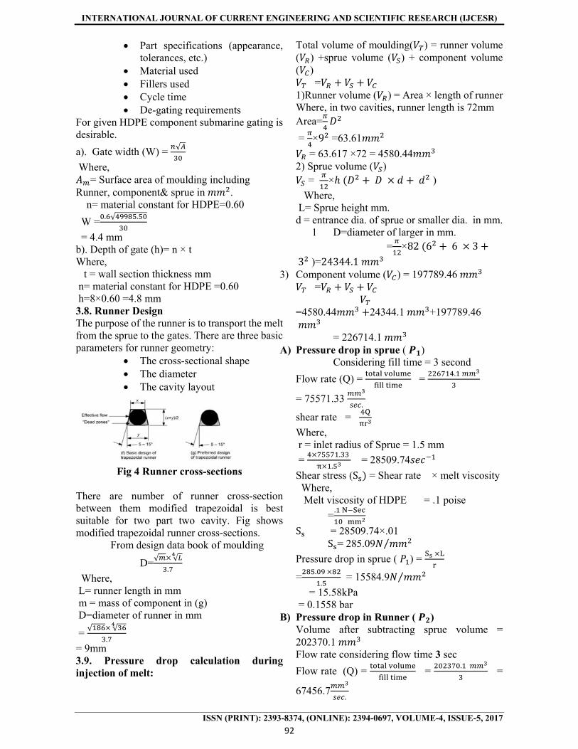
= 4.4 mm b). Depth of gate (h)= n × t Where, t = wall section thickness mm n= material constant for HDPE =0.60 h=8×0.60 =4.8 mm 3.8. Runner Design The purpose of the runner is to transport the melt from the sprue to the gates. There are three basic parameters for runner geometry:
The cross-sectional shape The diameter The cavity layout
Fig 4 Runner cross-sections
There are number of runner cross-section between them modified trapezoidal is best suitable for two part two cavity. Fig shows modified trapezoidal runner cross-sections.
From design data book of moulding
D=√ √
.
Where, L= runner length in mm m = mass of component in (g) D=diameter of runner in mm
= √ √
.
= 9mm 3.9. Pressure drop calculation during injection of melt:
Total volume of moulding( ) = runner volume ( ) +sprue volume ( ) + component volume ( )
= 1)Runner volume ( ) = Area × length of runner Where, in two cavities, runner length is 72mm Area=
= ×9 =63.61
= 63.617 ×72 = 4580.44 2) Sprue volume ( )
= × )
Where, L= Sprue height mm. d = entrance dia. of sprue or smaller dia. in mm. 1 D=diameter of larger in mm. = ×82 6 6 33 )=24344.1
3) Component volume ( ) = 197789.46 =
=4580.44 24344.1 +197789.46 = 226714.1
A) Pressure drop in sprue ( ) Considering fill time = 3 second
Flow rate (Q) =
=
.
= 75571.33 .
shear rate =
Where, r = inlet radius of Sprue = 1.5 mm
= .
. = 28509.74
Shear stress (S = Shear rate × melt viscosity Where, Melt viscosity of HDPE = .1 poise
=.
S = 28509.74×.01 S = 285.09 ⁄
Pressure drop in sprue ( ) =
=.
. = 15584.9 ⁄
= 15.58kPa = 0.1558 bar
B) Pressure drop in Runner ( ) Volume after subtracting sprue volume = 202370.1 Flow rate considering flow time 3 sec
Flow rate (Q) =
=
. =
67456.7.

INTERNATIONAL JOURNAL OF CURRENT ENGINEERING AND SCIENTIFIC RESEARCH (IJCESR)
ISSN (PRINT): 2393-8374, (ONLINE): 2394-0697, VOLUME-4, ISSUE-5, 2017
93
Shear rate =
Where, r = inlet radius of runner= 4 mm
= .
= 1342.008 Shear stress (S = Shear rate × melt viscosity Where, Melt viscosity of HDPE= .1 poise
= .
S = 1342.008×.01 = 13.42008 ⁄
Pressure drop in Runner ( ) =
= .
. = 440.178 ⁄
= 0.440178 kPa = 0.00440178 bar Total Pressure drop in mould flow system ( ) = + = 0.1558 bar + 0.00440178 bar =0.16020 bar 6.9 Mould cooling Calculation.
a) Mass of moulding including runner &sprue = V× ρ = 197789.46×0.94×10 Where, V=for two componentv×1=197789.46 ×1=197789.46 =186 g = 0.186 Kg Maximum wall thickness of component = 8mm From machine specification plasticizing capacity of SP-130-73.8 kg/hr. Mass of moulding =0.186 kg b)Rate of Production =
= . /
. = 396.77 no’s
But in actual practice mould opening take some time. Therefore, considering rate of production less than obtained by theoretically. Rate of Production=125nos. c)Total heat content in HDPE moulding in one hour =125 ×0.186 ×718.2 =16698 kJ/hr. Density of HDPE =0.94 g/ d)Mass of plastic material injected in to mould= mass of moulding rate of production =0.186 125=23.2kg e)Heat to be transferred from mould per hour
)
=m Where
= Heat content of HDPE=718.2 kJ/kg m = Mass of plastic material injected in to mould (kg)
=23.2 ×718.2=16662 kJ/hr. But in actual practice half of heat to be transferred to the mould & other half of the heat removed by the conventional methods of heat transfer such as convection, conduction. Therefore,
= 166.62/2 =8331.12 kJ/hr. f)Amount of water to be circulated per hour ( )
= k ( - )× Where,
= mass of water circulated = specific heat capacity of water
=4200J/kg k =4.2 kJ/kgk ( - ) is usually 3 to 5 K= constant to allow for heat transfer efficiency But in practice,
= = k ( - ) ×
=
= .
. . =619.87 kg/hr.
g) Solidifying time (T)
T= .
×
Where, ρ = density of HDPE kg/
a = Heat content of HDPE=718.2 kJ/kg λp= thermal conductivity of HDPE=0.52 ⁄ =0.52×1000kw/mk t = Maximum wall thickness of component = 8mm =0.008m
.=melting temperature of HDPE in K .=temperature of mould in K
T= .
. × =51.931 = 52 second
l) Minimum clamping force required (F), F= projected area ×pressure in cavity F = 5080.9 × 63 = 32620.12 kg Where, Pressure in cavity is considered as63 Mpa Minimum clamping force required (F) =32.62 tons m) Injection pressure from machine specification = 2200 bar
IV SELECTION OF MOULD BASE There are no of mould base manufacturing companies like DME, HASCO, DMS, etc.

INTERNATIONAL JOURNAL OF CURRENT ENGINEERING AND SCIENTIFIC RESEARCH (IJCESR)
ISSN (PRINT): 2393-8374, (ONLINE): 2394-0697, VOLUME-4, ISSUE-5, 2017
94
For two cavity of given HDPE component following K-std, mould base selected.
V DETAILS AND ASSEMBLY

INTERNATIONAL JOURNAL OF CURRENT ENGINEERING AND SCIENTIFIC RESEARCH (IJCESR)
ISSN (PRINT): 2393-8374, (ONLINE): 2394-0697, VOLUME-4, ISSUE-5, 2017
95

INTERNATIONAL JOURNAL OF CURRENT ENGINEERING AND SCIENTIFIC RESEARCH (IJCESR)
ISSN (PRINT): 2393-8374, (ONLINE): 2394-0697, VOLUME-4, ISSUE-5, 2017
96
22 DOWEL STD 02 Ø80 50-60
21 GUIDE BUSH FOR KNOCK OUT
En31 01 Ø28×20
-
20 GUIDE BUSH
En31 04 Ø42×76
60-62
19 CAP SCREW STD 04 M4×0.75×40
-
18 CAP SCREW STD 01 M6×1×40
-
17 KNOCKOUT BAR
STD 01 Ø24×120
-
16 SPRUE PULLER
En31 01 Ø6×116
60-62
15 PUSH BACK PIN
En31 02 Ø6×113
60-62
14 EJECTOR PIN
En31 05 Ø4×10⁹
60-62
13 REST BUTTON
En8 06 Ø30×08
48-52
12 CAP SCREW STD 04 M10×1.5×75
-
11 EJECTOR PLATE
M.S 01 496×250×36
-
10 RETAINER PALTE
En31 01 496×250×27
48-52
09 BACK PLATE
M.S 01 546×546×46
-
08 SPACER M.S 02 496×46 -
07 CORE BACK PLATE
M.S 01 496×496×46
-
06 CORE PLATE
H13 01 496×496×36
50-54
05 GUIDE PILLER
En31 04 60-62
04 CAVITY PLATE
H13 01 496×496×36
50-54
03 FRONT PLATE
M.S 01 546×546×46
-
02 SPRUE BUSH
En31 01 Ø38×82
60-62
01 LOCATING RING
M.S 01 Ø120×15
-
PART NO.
DESCRIPTION
MATERIAL
QTY FINISH SIZE
HRC

INTERNATIONAL JOURNAL OF CURRENT ENGINEERING AND SCIENTIFIC RESEARCH (IJCESR)
ISSN (PRINT): 2393-8374, (ONLINE): 2394-0697, VOLUME-4, ISSUE-5, 2017
97
Final Assembly Drawing
Bill of Material VI PROCESS PLANNING AND DETAILS: - As work piece quantities and costs in mould are usually high, considerable economy can be affected by choosing an appropriate sequence of operations and the right type of tooling. The process plan should take into account the total cost: material, tooling, labor (time). Process planning generally includes the following considerations.
Quantity required – total and annual, Work piece – shape and size, Work piece – dimensional tolerances, Work piece – material limitations, Equipment available for manufacturing.
In every tool, the process planning done a vital role and it is followed by above mentioned points. To manufacture the parts of the tool, it is necessary to follow the proper methodology of manufacturing, so that one can get accurate dimensional stability for that particular part within appropriate time. In Mould also all the parts of the tool are manufactured by considering all above mentioned sequence and choosing of machining sequence. Below mentioned sheet expresses all the view of machining sequence of the tool. Similarly, all the parts of the tool are manufactured by the same followed suit. 1) Design stage: - After designing the tool prepared the individual part drawings for manufacturing the parts & assembly drawing. Then print out are taken & filled them in process planning. 2) Manufacturing stages: After getting the part drawings material requisition is raised to the store department. Then raw material is cut according to make drawing size with suitable allowances in size. Then pre-
INTERNATIONAL JOURNAL OF CURRENT ENGINEERING AND SCIENTIFIC RESEARCH (IJCESR)
ISSN (PRINT): 2393-8374, (ONLINE): 2394-0697, VOLUME-4, ISSUE-5, 2017
98
machining is done according to size with grinding allowances in size. After maintaining the dimensions & references bench work is completed on the plates, like drilling, tapping. 3) Precise operations: - In the mould tool the accuracy depends upon the size of the core & cavity. So a lot of concentration is made on manufacturing of core & cavity. The core & cavity size manufactured within the required tolerances & maintaining their clearances. 4) Heat treatment: - In heat treatment stage we have to plan for sequence of component to be heat-treated this is important because according to this sequence we have to manufacture component. 5) Assembly stage: - As we order for mould base to venders, only mfg. Of insert and other component is to plan for proper flow. 6.1MANUFACTURINGPROCESSES PLANNING: -
All the features of the part with dimensions & their references with respect to the assembly.
The part is studies and the plans for sequence of process like conventional, non-conventional & CNC machining, heat treatment in process & stage inspection etc.
Special requirements for the tooling, electrode, and CAD/CAM support for the programs required for the Core & Cavity inserts that are to be machined on the CNC machines etc. are planned in advance to meet the process flow & to maintain the delivery schedule.
Stage drawings of each parts coming & going out from process are made for the convenience of the machine operator showing the references, tolerance analysis, manufacturing allowances using the ordinate dimensioning and inspection methodology.
A continuous follow up for the machine availability is made for the completion of the job in the planned time period to maintain the delivery date.
The above information is applied for all processes related to the part indicating earliest start & finish date of each process with respect to material planning, date of availability of special tooling, electrode, CAD/CAM data, monthly priority list etc. The start & finish date can be taken from the job cards the earliest finish date of assembly can be analyzed for the first trial and
is communicated to all the interface departments about planning and their support. 6.2 MANUFACTURING PROCESSES PLANNING FOR EACH PART
All the features of the part with dimensions & their references with respect to the assembly.
The part is studies and the plans for sequence of process like conventional, non-conventional & CNC machining, heat treatment in process & stage inspection etc.
Special requirements for the tooling, electrode, and CAD/CAM support for the programs required for the Core & Cavity inserts that are to be machined on the CNC machines etc. are planned in advance to meet the process flow & to maintain the delivery schedule.
Stage drawings of each parts coming & going out from process are made for the convenience of the machine operator showing the references, tolerance analysis, manufacturing allowances using the ordinate dimensioning and inspection methodology.
A continuous follow up for the machine availability is made for the completion of the job in the planned time period to maintain the delivery date. The above information is applied for all processes related to the part indicating earliest start & finish date of each process with respect to material planning, date of availability of special tooling, electrode, CAD/CAM data, monthly priority list etc. The start & finish date can be taken from the job cards the earliest finish date of assembly can be analyzed for the first trial and is communicated to all the interface departments about planning and their support.
VII CONCLUSION A complete mould designer must have a thorough knowledge of the principles of the mould making as the design of the various parts of the mold depends on the technique adopted for its manufacturer. Case studies of the various mould of same kind have been conducted prior to the design process. Proper evaluation of the previous designs was performed and created something even better instead of simply keeping to what was done previously. The various demands of the customer were considered while designing of the tool. The final mould design is prepared after the part design has been specified and all requirements affecting the design of mould have been clarified. The outcome is a near perfect design and the trail made on the mould just about confirms it.

INTERNATIONAL JOURNAL OF CURRENT ENGINEERING AND SCIENTIFIC RESEARCH (IJCESR)
ISSN (PRINT): 2393-8374, (ONLINE): 2394-0697, VOLUME-4, ISSUE-5, 2017
99
REFERENCES [1] C.L. Li A feature-based approach to injection mould cooling system design Computer-Aided Design 33 2001) 1073±1090 [2] M.W. Fu The application of surface demoldability and moldability to side-core design in die and mold CAD Computer-Aided Design 40 (2008) 567–575 [3] Hsien-Chang Kuo, Ming-Chang Jeng The influence of injection molding on tribological characteristics of ultra-high molecular weight polyethylene under dry sliding Wear 268 (2010) 803–810. [4] Seong Yeol Hana,,Jin-Kwan Kwag, Cheol-Ju Kimb, Tae-Won Park , Yeong Deug Jeong A new process of gasassisted injection molding for faster cooling Journal of Materials Processing Technology 155–156 (2004) 1201– 1206. [5] Ozcelik , T. Erzurumlu Gebze Comparison of the warpage optimization in the plastic injection molding using ANOVA, neural network model and genetic algorithm. Journal of Materials Processing Technology 171 (2006) 437– 445 [6] Julian M. Lippmann, Emil J. Geiger, Albert P. Pisano Polymer investment molding: Method for fabricating hollow, microscale parts,Sensors and Actuators A 134 (2007) 2–10 [7] Zone-Ching Lin and Ming-Ho Chou, Design of the Cooling Channels in Nonrectangular
Plastic Flat Injection Mold .journals of manufacturing system vol.21/no.3 2002. [8] B. Nardin, K. Kuzman, Z. Kampus Injection moulding simulation results as an input to the injection moulding process Journal of Materials Processing Technology 130–131 (2002) 310–314. [9] L. Kong, J.Y.H. Fuh, K.S. Lee, X.L. Liu, L.S. Ling, Y.F. Zhang, A.Y.C. Nee A Windows-native 3D plastic injection mold design system Journal of Materials Processing Technology 139 (2003) 81–89. [10]M.C. Song, Z. Liu, M.J. Wang, T.M. Yu, D.Y. Zhao . Research on effects of injection process parameters on the molding process for ultra-thin wall plastic parts Journal of Materials Processing Technology 187–188 (2007) 668– 671 [11]T. Boronat, V.J. Segui, M.A. Peydro, M.J. Reig. Influence of temperature and shear rate on the rheology and processability of reprocessed ABS in injection molding process. journal homepage: www.elsevier.com/locate/jmatprotec. [12]H.J. Leea, B.D. Jooa, Y.B. Moonb, C.J. Van Tynec, Y.H. Moona, The die turning injection (DTI) process for the fabrication of hollow parts .Journal of Materials Processing Technology. j o ur nal ho me p age : www.elsevier.com/locate/jmatprotec