
Design and Evaluation of a New Boundary-Layer Rake for ... · Design and Evaluation of a New...
21
NASA/TM-2000-209014 Design and Evaluation of a New Boundary-Layer Rake for Flight Testing Trong T. Bui and David L. Oates NASA Dryden Flight Research Center Edwards, California Jose C. Gonsalez Dynacs Engineering Co., Inc. Brookpark, Ohio January 2000
Transcript of Design and Evaluation of a New Boundary-Layer Rake for ... · Design and Evaluation of a New...

NASA/TM-2000-209014
Design and Evaluation of a New Boundary-Layer Rake for Flight Testing
Trong T. Bui and David L. OatesNASA Dryden Flight Research Center Edwards, California
Jose C. GonsalezDynacs Engineering Co., Inc.Brookpark, Ohio
January 2000

The NASA STI Program Office…in Profile
Since its founding, NASA has been dedicatedto the advancement of aeronautics and space science. The NASA Scientific and Technical Information (STI) Program Office plays a keypart in helping NASA maintain thisimportant role.
The NASA STI Program Office is operated byLangley Research Center, the lead center forNASA’s scientific and technical information.The NASA STI Program Office provides access to the NASA STI Database, the largest collectionof aeronautical and space science STI in theworld. The Program Office is also NASA’s institutional mechanism for disseminating theresults of its research and development activities. These results are published by NASA in theNASA STI Report Series, which includes the following report types:
• TECHNICAL PUBLICATION. Reports of completed research or a major significantphase of research that present the results of NASA programs and include extensive dataor theoretical analysis. Includes compilations of significant scientific and technical data and information deemed to be of continuing reference value. NASA’s counterpart of peer-reviewed formal professional papers but has less stringent limitations on manuscriptlength and extent of graphic presentations.
• TECHNICAL MEMORANDUM. Scientificand technical findings that are preliminary orof specialized interest, e.g., quick releasereports, working papers, and bibliographiesthat contain minimal annotation. Does notcontain extensive analysis.
• CONTRACTOR REPORT. Scientific and technical findings by NASA-sponsored contractors and grantees.
• CONFERENCE PUBLICATION. Collected papers from scientific andtechnical conferences, symposia, seminars,or other meetings sponsored or cosponsoredby NASA.
• SPECIAL PUBLICATION. Scientific,technical, or historical information fromNASA programs, projects, and mission,often concerned with subjects havingsubstantial public interest.
• TECHNICAL TRANSLATION. English- language translations of foreign scientific and technical material pertinent toNASA’s mission.
Specialized services that complement the STIProgram Office’s diverse offerings include creating custom thesauri, building customizeddatabases, organizing and publishing researchresults…even providing videos.
For more information about the NASA STIProgram Office, see the following:
• Access the NASA STI Program Home Pageat
http://www.sti.nasa.gov
• E-mail your question via the Internet to [email protected]
• Fax your question to the NASA Access HelpDesk at (301) 621-0134
• Telephone the NASA Access Help Desk at(301) 621-0390
• Write to:NASA Access Help DeskNASA Center for AeroSpace Information7121 Standard DriveHanover, MD 21076-1320

NASA/TM-2000-209014
Design and Evaluation of a New Boundary-Layer Rake for Flight Testing
Trong T. Bui and David L. OatesNASA Dryden Flight Research Center Edwards, California
Jose C. GonsalezDynacs Engineering Co., Inc.Brookpark, Ohio
January 2000
National Aeronautics andSpace Administration
Dryden Flight Research CenterEdwards, California 93523-0273

NOTICE
Use of trade names or names of manufacturers in this document does not constitute an official endorsementof such products or manufacturers, either expressed or implied, by the National Aeronautics andSpace Administration.
Available from the following:
NASA Center for AeroSpace Information (CASI) National Technical Information Service (NTIS)7121 Standard Drive 5285 Port Royal RoadHanover, MD 21076-1320 Springfield, VA 22161-2171(301) 621-0390 (703) 487-4650

DESIGN AND EVALUATION OF A NEW BOUNDARY-LAYER RAKE FOR FLIGHT TESTING
Trong T. Bui* and David L. Oates†
NASA Dryden Flight Research CenterEdwards, California
Jose C. Gonsalez‡
Dynacs Engineering Co., Inc.Brookpark, Ohio
d
kr
i
d
-
Abstract
A new boundary-layer rake* has been designed anbuilt for flight testing on the NASA Dryden FlightResearch Center F-15B/Flight Test Fixture.† A featureunique to this rake is its curved body, which allows pittubes to be more densely clustered in the near-wregion than conventional rakes allow.‡ This curved rakedesign has a complex three-dimensional shape trequires innovative solid-modeling and machinintechniques. Finite-element stress analysis of the ndesign shows high factors of safety. The rake has pasa ground test in which random vibration measurin12 g rms was applied for 20 min in each of the threnormal directions. Aerodynamic evaluation of the rahas been conducted in the NASA Glenn ReseaCenter 8 × 6 Supersonic Wind Tunnel at Mach 0–2. Thpitot pressures from the new rake agree wconventional rake data over the range of Mach numbtested. The boundary-layer profiles computed from trake data have been shown to have the standlogarithmic-law profile. Skin friction values computefrom the rake data using the Clauser plot method agwith the Preston tube results and the van Driestcompressible skin friction correlation to approximate±5 percent.
*Aerospace Engineer. Member AIAA.†Aerospace Engineering Technician.‡Wind-Tunnel Test Engineer. Member AIAA.
1American Institute of Ae
Copyright 2000 by the American Institute of Aeronautics anAstronautics, Inc. No copyright is asserted in the United States unTitle 17, U.S. Code. The U.S. Government has a royalty-free liceto exercise all rights under the copyright claimed herein for Govemental purposes. All other rights are reserved by the copyright own
dder
nsern-er.
otall
hatgewsedgeechethersheard
reeII
ly
Nomenclature
Acronyms
ESP electronically scanned pressure
FOS factor of safety
FTF Flight Test Fixture
LSWT 9 × 15 Low-Speed Wind Tunnel
OD outer diameters
SWT 8 × 6 Supersonic Wind Tunnel
Symbols
B logarithmic-law constant, B = 5
skin friction coefficient transformed into the incompressible plane by the van Driest II transformation
g gravitational acceleration constant,32.2 ft/sec2
M Mach number
P pressure
Reynolds number based on the boundarylayer momentum thickness transformedinto the incompressible plane by the van Driest II transformation
rms root-mean-square
T temperature
U stream-wise velocity
van Driest effective velocity
Cf
Reθ
U+ ueq
uτ--------
ueq
ronautics and Astronautics
forsehehtF
dhe
the
mntodic-enqueeall
lso
keessond
thenelrch
0are
of anrs,ics
kesed
en.all
wall friction velocity,
y normal distance from the wall
distance in wall units,
logarithmic-law constant, = 0.41
viscosity coefficient
density
shear stress
Subscripts
aw adiabatic-wall conditions
conv conventional rake used in wind-tunnel testing
e edge of boundary layer
new new rake
pitot pitot tube readings
tunnel_totalwind-tunnel total conditions
w wall conditions
Introduction
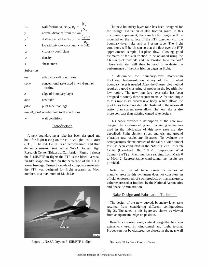
A new boundary-layer rake has been designed andbuilt for flight testing on the F-15B/Flight Test Fixture(FTF).1 The F-15B/FTF is an aerodynamics and fluiddynamics research test bed at NASA Dryden FlightResearch Center (Edwards, California). Figure 1 showsthe F-15B/FTF in flight; the FTF is the black, vertical,fin-like shape mounted on the centerline of the F-15Blower fuselage. Primarily made of composite materials,the FTF was designed for flight research at Machnumbers to a maximum of Mach 2.0.
Figure 1. NASA Dryden F-15B/FTF in flight.
The new boundary-layer rake has been designed the in-flight evaluation of skin friction gages. In thiupcoming experiment, the skin friction gages will bmounted on the surface of the FTF together with tboundary-layer rake and a Preston tube. The fligconditions will be chosen so that the flow over the FTapproximates simple flat-plate flow, allowing gooestimates of the skin friction to be obtained using tClauser plot method2 and the Preston tube method.3
These estimates will then be used to evaluate performance of the skin friction gages in flight.
To determine the boundary-layer momentuthickness, high-resolution survey of the turbuleboundary layer is needed. Also, the Clauser plot methrequires a good clustering of probes in the logarithmlaw region. The new boundary-layer rake has bedesigned to satisfy these requirements. A feature unito this rake is its curved rake body, which allows thpitot tubes to be more densely clustered in the near-wregion than current rakes allow. The new rake is amore compact than existing canted rake designs.
This paper provides a description of the new radesign. The solid-modeling and machining techniquused in the fabrication of this new rake are aldescribed. Finite-element stress analysis and grouvibration test results are discussed. To evaluate aerodynamics characteristics of the rake, a wind-tuntest has been conducted in the NASA Glenn ReseaCenter (Cleveland, Ohio)§ 8 × 6 Supersonic WindTunnel (SWT) at Mach numbers ranging from Machto Mach 2. Representative wind-tunnel test results provided.
Note that use of trade names or names manufacturers in this document does not constituteofficial endorsement of such products or manufactureeither expressed or implied, by the National Aeronautand Space Administration.
Rake Design and Fabrication Technique
The design of the new, curved, boundary-layer raresulted from considering different configuration(fig. 2). The rakes in this figure are shown as viewfrom an upstream, edge-on position.
Rake A is a conventional, vertical design that has beextensively used in wind-tunnel and flight testingProbes can not be clustered too closely in the near-w
uτ uττw
ρw------=
y+
y+ ρwuτy
µw---------------=
κ κ
µ
ρ
τ
FTF
990347
§Formerly NASA Lewis Research Center.
2American Institute of Aeronautics and Astronautics

D.ors,a
alvedicaloreallbeeserersl
of a anl isheonale of
ss
ss a thetedterakeseee
A B C D990348
Figure 2. Rake designs considered.
region of this rake design because of interferenceeffects; therefore, the rake resolution in the near-wallregion could be insufficient. Rake B was designed toovercome this problem. This rake is canted at an angleto the surface, which allows smaller probe spacing in thevertical direction near the wall than rake A allows. Themajor drawbacks of this approach are that the boundarylayer is assumed to be uniform over a large span-wiseregion, and that the canted rake requires additional roomto install and interferes with or obscures otherinstrumentations nearby. As an example, the canted rakethat has been used on the FTF covers as much as 5 in. inthe span-wise direction.
A new semicanted rake design, rake C, wasconsidered in which the canted portion covers only thenear-wall region and the rake becomes vertical awayfrom the wall where the tight probe spacing is notneeded. This design retains the desirable probeclustering feature of rake B in the near-wall region but ismuch more compact in the span-wise direction.Unfortunately, the sharp angles in the rake C designpresent manufacturing and structural problems.
Rounding out the sharp angles in rake C led to therake D design. The curved lower portion of rake Dallows tighter probe clustering in the vertical directionthan was possible with the canted rakes. The lowerportion is smoothly blended into the vertical upperportion of the rake, resulting in a compact rake withvery good probe clustering characteristics in the near-wall region.
Note that the pitot probes in rakes B–D are distributedover a distance in the span-wise direction. These rakedesigns should be used only when the boundary layer isexpected to be homogeneous in the span-wise direction.
Several possible design variations exist to rake Total pressure probes can be replaced by other senssuch as total temperature probes, that will allow distribution of fluid dynamic properties other than totpressures to be measured. The circular arc in the curportion of the rake can be replaced by other geometrshapes (parabola, hyperbola, and so forth) to allow mcontrol in the degree of probe clustering in the near-wregion. Additionally, a second curved section can used above the rake. This modification will allow probto be tightly clustered at both of the upper and lowends of the rake, thereby resolving both boundary layat the two solid walls in the flow (for example, internafluid flows in inlets, ducts, and nozzles).
New Rake Design
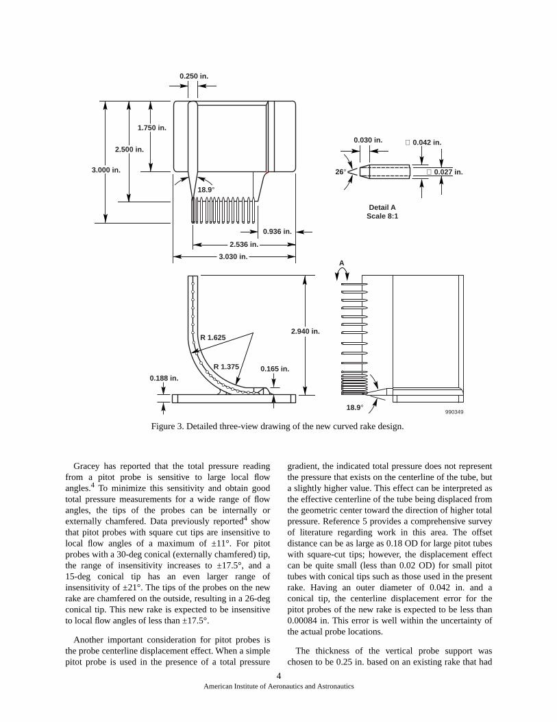
Figure 3 shows a three-view engineering drawing the new rake design. The new rake consists ofhorizontal rake pedestal, a vertical probe support, andarray of total pressure probes. The rake pedestamounted flush with the surface to be surveyed. Tvertical probe support consists of a curved lower portiand a straight vertical upper portion. An array of totpressure probes is mounted along the upstream edgthe vertical probe support.
Current analysis of boundary-layer velocity profileon the FTF collected during past F-15B flight test1
shows that the logarithmic-law region extendapproximately 0.5 in. above the surface of the FTF. Aresult, the probes are spaced on the curved portion ofnew rake such that approximately ten probes are locain the first 0.5 in., spaced approximately two probe oudiameters (OD) apart. The remaining probes on the rare spaced approximately 3.75 OD apart. Thespacings will provide good probe clustering in thlogarithmic-law region and give good coverage for thentire FTF turbulent boundary layer.
3American Institute of Aeronautics and Astronautics
ent butasm
talrveyetbesctotent
ae
hanf
ashad
18.9°
0.936 in.
0.250 in.
0.030 in. ∅ 0.042 in.
∅ 0.027 in.
Detail AScale 8:1
26°
- - - - - - - - - -
- - - - - - - - - -18.9°
990349
A
R 1.625
0.188 in.0.165 in.R 1.375
3.000 in.
2.500 in.
1.750 in.
3.030 in.
2.536 in.
2.940 in.
Figure 3. Detailed three-view drawing of the new curved rake design.
Gracey has reported that the total pressure readingfrom a pitot probe is sensitive to large local flowangles.4 To minimize this sensitivity and obtain goodtotal pressure measurements for a wide range of flowangles, the tips of the probes can be internally orexternally chamfered. Data previously reported4 showthat pitot probes with square cut tips are insensitive tolocal flow angles of a maximum of ±11°. For pitotprobes with a 30-deg conical (externally chamfered) tip,the range of insensitivity increases to ±17.5°, and a15-deg conical tip has an even larger range ofinsensitivity of ±21°. The tips of the probes on the newrake are chamfered on the outside, resulting in a 26-degconical tip. This new rake is expected to be insensitiveto local flow angles of less than ±17.5°.
Another important consideration for pitot probes isthe probe centerline displacement effect. When a simplepitot probe is used in the presence of a total pressure
gradient, the indicated total pressure does not represthe pressure that exists on the centerline of the tube,a slightly higher value. This effect can be interpreted the effective centerline of the tube being displaced frothe geometric center toward the direction of higher topressure. Reference 5 provides a comprehensive suof literature regarding work in this area. The offsdistance can be as large as 0.18 OD for large pitot tuwith square-cut tips; however, the displacement effecan be quite small (less than 0.02 OD) for small pittubes with conical tips such as those used in the presrake. Having an outer diameter of 0.042 in. andconical tip, the centerline displacement error for thpitot probes of the new rake is expected to be less t0.00084 in. This error is well within the uncertainty othe actual probe locations.
The thickness of the vertical probe support wchosen to be 0.25 in. based on an existing rake that
4American Institute of Aeronautics and Astronautics

e-kere tothet,
akem
gke
theiveelon.f;es
been used on the F-15B airplane. Gettelman and Krausefound that the pitot probe support could interfere withthe probe reading.6 This interference effect is reduced asthe distance between the probe tip and probe support isincreased, and asymptotes to a minimum value for theratios of probe length to probe support thickness greaterthan 3. In the new rake, the probe tip is located 1.75 in.upstream of the maximum thickness location of thesupport, giving a ratio of pitot probe length to supportthickness of 5.
Rake Fabrication Techniques
Although the curved rake concept described above isquite simple, the mechanical design and fabrication ofthe actual hardware were very challenging. Thethree-dimensional design consists of a large number ofcurves and angles. In addition, the actual rake needs tobe rugged to withstand supersonic wind-tunnel andaircraft operation, and provisions need to be made forrouting and installing the pitot tubes. Consequently,innovative three-dimensional–solid-modeling andmachining techniques were required.
Starting from a three-view conceptual sketch, athree-dimensional solid model was constructed usingthree-dimensional–solid-modeling software. The samesoftware was used throughout the entire design andmachining process, ensuring accurate machining of therake from the three-dimensional solid model. The actualrake body needed to be strong and streamlined, andprovisions had to be made for the installation androuting of the stainless-steel pitot tubes.
After a solid model was created, a computer-controlled electrical discharge machine was used with a0.010-in. wire to cut the basic shape of the rake body outof a solid block of aluminum alloy 2024-T351. (Theresidual piece of aluminum with the outside contour ofthe rake was saved and used as a fixture for the rakeduring subsequent machining work.) The rake was thenmachined on a computer–numerically controlled millingmachine. First, the rake pedestal was machined for flushmounting on a flat surface. To make room for theinstallation of the pitot tubes, a cavity was machined inseveral steps inside the rake body. Then, mounting holesfor the pitot tubes were drilled on the rake leading edge,and the leading edge was tapered to an angle of 18.9°.To close off the cavity in the rake body, an aluminumrake cover was created using the wire electricaldischarge machine.
The pitot tubes used in the rake were fabricated fromT304 stainless-steel tubing (0.042-in. outer diameter
and 0.0075-in. nominal-wall thickness, annealed to onhalf hard condition). As discussed in the New RaDesign section, the tips of the pitot tubes wechamfered on the outside to reduce their sensitivitylocal flow angles. Then the probes were inserted into rake body. A low-viscosity, single-componenanaerobic, methacrylate ester adhesive, Loctite® 609¶
was used to hold the pitot tubes in place inside the rbody. To cushion the pitot tubes and protect them frovibration during flight, room-temperature–vulcanizinsilicone rubber was applied to the inside of the racavity.
Figure 4 shows the finished rake. The surface of rake body was anodized to help protect it from corroseffects during high-speed–aircraft and wind-tunnoperation. Figure 4(a) shows the rake with the cover Figure 4(b) shows the rake with the cover ofinstallation and routing inside the rake of the pitot tubcan be seen in this view.
EC 98 44775-04
(a) Rake with cover on.Figure 4. The new, curved, boundary-layer rake.
¶Loctite Corporation, Rocky Hill, Connecticut.
5American Institute of Aeronautics and Astronautics

mnic,ot
nic by at
omtosre
ndstochd
ral
of ft.ive
onbeor
EC 98 44775-03
(b) Rake with cover off.Figure 4. Concluded.
Flight Qualification Analysis and Testing
To determine the structural integrity of the new rake,finite-element stress analysis was conducted for bothwind-tunnel and aircraft operations. Factors of safetywere computed from the solutions of the finite-elementanalysis. Also, a ground vibration test on the rake wasconducted at NASA Dryden.
Finite-Element Stress Analysis
To qualify the rake for supersonic wind-tunneloperation, the computer solid model was analyzed usingthe COSMOS/Works™# finite-element analysispackage. Inviscid flow theory was used to obtain thepressure distribution on the rake body. In thefinite-element analysis, the pressures were specified asboundary conditions while the base of the rake was heldrigidly fixed. The static stress analysis was conductedusing the fast finite-element (FFE) solver option inCOSMOS/Works™. This fast, robust, and accuratefinite-element solver provides solutions significantlyfaster than standard finite-element direct solvers. Thefinite-element mesh used in the analysis wasautomatically generated by COSMOS/Works™ usingthe default high-quality meshing option.
The factor of safety (FOS), based on the maximuvon Mises stress, was computed for subsonic, transoand supersonic wind-tunnel test conditions (with nsideslip) from the solutions of the finite-elemenanalysis. Table 1 shows a summary of the results.
The stress on the rake is most severe in the transoMach number range. This severe stress is causedhigh pressure from the detached normal shock wavethe rake leading edge. The minimum FOS ranges frapproximately 10 for transonic Mach numbers approximately 100 for low subsonic Mach numbers. Aexpected, no structural problems with the rake wefound during the actual supersonic wind- tunnel test.
A similar stress analysis was done for straight alevel flight conditions for the F-15B/FTF. Table 2 showa summary of the results. Altitudes from sea level 45,000 ft were considered at 5,000 ft intervals. At eaaltitude, the maximum flight Mach number obtainefrom the F-15B/FTF flight envelope1 was used tocalculate the aerodynamic loads and the structustresses on the rake.
The FOS ranged from 12 at Mach 1 and an altitude10,000 ft to 37 at Mach 2 and an altitude of 45,000Because of the high FOS, the rake is expected to survF-15B/FTF straight and level flight operationthroughout the entire flight envelope. The side loads the rake and new factors of safety will need to determined for flight tests with large angles of attack sideslip.
#Structural Research & Analysis Corporation, Los Angeles,California.
Table 1. Minimum factors of safety for wind-tunneltest conditions.
Mach number Factor of safety
2.0 26
1.8 21
1.6 17
1.4 11
1.2 13
0.9 26
0.6 42
0.4 98
6American Institute of Aeronautics and Astronautics

und
ewrew,nalheedter,asd-ofing
Tesionallllin.
er.esity
Ground Vibration Test
Flight equipment on the F-15B/FTF is required atNASA Dryden to be tested to worst-case operatingconditions. As part of this requirement, a groundvibration test was conducted on the rake. In this test, therake was securely mounted on a vibration table andrandom vibration measuring 12 g rms was applied for20 min in each of the three normal directions. Thefrequency for the vibration test ranged from 15 to2000 Hz. Accelerometers were affixed to the mountingfixture and the side of the rake to document the
acceleration on the rake. The rake passed the grovibration test with no anomalies.
Wind-Tunnel Testing of the Rake
To evaluate the aerodynamic performance of the nrake design, two different boundary-layer rakes weseparately tested in two wind-tunnel tests: the necurved rake and a rake representative of a conventiodesign. The wind-tunnel tests were conducted in tNASA Glenn SWT. The first test used the new curvrake; the second test, which took place one week laused the conventional rake. The conventional rake wused as a check for the new rake. Nearly identical wintunnel flow conditions were used for both tests. Both the tests were conducted for Mach numbers rangfrom 0.05 to 2.00.
Description of Facility
Figure 5 shows a plan view of the SWT and 9 × 15Low-Speed Wind Tunnel (LSWT) complex. The SWis an atmospheric tunnel with Mach number capabilitiranging from 0.0 to 0.1 and 0.25 to 2.0. The test secthas two parts: a solid-wall section and a porous-wsection. The forward 9-ft, 1-in. section is the solid-wasupersonic test section. The downstream 14-ft, 5-section is the porous-wall transonic test section.
The test section is housed in a vacuum chambDuring tunnel operation, the vacuum chamber providbleed to the transonic test section through the poros
Table 2. Minimum factors of safety for F-15B/FTF straight and level flight conditions.
Altitude, ft Mach number Factor of safety
0 0.907 16
5,000 0.979 17
10,000 1.057 12
15,000 1.143 12
20,000 1.242 12
25,000 1.356 12
30,000 1.489 13
35,000 1.646 25
40,000 1.829 31
45,000 2.038 37
7American Institute of Aeronautics and Astronautics
Turn 1 Flow High-speed diffuser
Shock doors
Screen and honeycomb flow conditioners
Seven-stage axial compressor
Flexible wall nozzle
Flow
Turn 3
990350Doors 4 and 5
Low-speed diffuser
Air dryer building with 8 large fans
Drive motor building housing three 29,000 hp electric motors
Balance chamber
8 x 6 test section 0 < M < 0.1 and 0.25 < M < 2.0– –
–
–
–
Aco
ust
ic m
uff
ler
Turn 2
Cooler
Screen and honeycomb flow conditioners
9 x 15 test section 0 < M < 0.2–
GridNorth
Doors 1 and 2 Door 3
N 37.856°
Figure 5. Plan view of the NASA Glenn SWT and LSWT complex.

ive
es.kee
in.,theed
hers, isis
Tsts). inreds
holes. This bleed allows regulation of the static pressurein the test section. During the rake tests, the wallpressure gradient in the stream-wise direction at the rakelocation was found to be negligible for most cases.
The SWT can be run in two modes. In theaerodynamic, or closed-loop, mode, air is continuallyrecirculated through the tunnel loop. In the propulsion,or open-loop, mode, air is drawn in throughdoorways 4 and 5 and exhausted through doorways1 and 2 (fig. 5). Door 3, which is directly at the entranceof the LSWT (fig. 5), is closed. Because air bypasses theLSWT in the open-loop mode, model work can occur inthe LSWT while the SWT operates.
During the tests described here, the boundary-layerrakes were installed on the ceiling and in the supersonicsolid-wall portion of the SWT test section. The SWToperated in propulsion, or open-loop, mode.
Test Hardware
Figures 6 and 7 show installation photographs of thetwo rakes. Also seen in these photographs is the0.125-in. outer diameter Preston tube, mounted side byside with the rakes. The outer diameter of the Prestontube was chosen specifically for the F-15B testconditions.7 (Full three-view drawings of the new rakeand the representative conventional rake are shown infigures 3 and 8, respectively.) Table 3 shows pitot probeheights for both rakes.
(Original photo courtesy of NASA Glenn Research Center)
Figure 6. Installation photograph of the new rake andPreston tube in the SWT.
(Original photo courtesy of NASA Glenn Research Center)
Figure 7. Installation photograph of the representatconventional rake and Preston tube in the SWT.
Many notable differences exist between the two rakThe new rake is curved, whereas the conventional rais vertically straight. Pitot tube outer diameters for thnew and conventional rakes are 0.042 and 0.188 respectively. Pitot tube lengths are 0.5 and 6.0 in. for curved and conventional rakes, respectively. The curvrake pitot tube tips have external chamfers; tconventional rake pitot tube tips have internal chamfeor countersinks. The overall height of the new rake2.94 in.; the overall height of the conventional rake 18.5 in.
Each rake was positioned on the ceiling of the SWin the forward, solid-wall portion of the supersonic tesection. The axial location of the pitot tube tips wa83.4 in. downstream of the tunnel zero station (fig. 9Each rake was centered along the tunnel centerlinethe span-wise direction. (The curved rake was centein the span-wise direction with respect to itmounting plate.)
Preston tube
New rake
990351
Preston tube
Conventionl rake
990352
8American Institute of Aeronautics and Astronautics

9
American Institute of Aeronautics and Astronautics
Figure 8. Detailed three-view drawing of the representative conventional boundary-layer rake.
A
1.00 in.
Probe tip detail
60°
1.00-in.spacing
0.50-in. spacing
0.25-in. spacing
0.75 in.
6.00 in.
6.00 in.
∅ 0.188 in.
12.7° 12.7°
990353
13.00 in.
A–A
18.50 in.
6.2°
9.5° 9.5°15.00 in.
Figure 9. Elevation of the SWT inlet contraction, flexible wall nozzle, and test section showing the axial location ofthe new and conventional boundary-layer rakes.
Flow
Inlet contractionFlexible wall nozzle
(floor and ceiling are flat)
Ceiling
Conventional and new rake axial location
Floor990354
83.4 in.
109 in.
Supersonictest
section
Transonic (porous)
test section
240 in. 96 in.
173 in.426 in.240 in.

ee
ivesely
pleneere
pleheles,izery-
ureest:d an
otnel
ESPa
d
e
P
es its at
stle, a
edure
.4,
tional
The Preston tube, which has an inner-diameter–to–outer-diameter ratio of 0.584, was installed at the sameaxial location as the boundary-layer rakes. Figure 10shows the location of the Preston tube as well as thelocations for surface temperature thermocouples andstatic pressure taps. The thermocouples and pressuretaps were used to provide local wall temperature andstatic pressure data needed in the boundary-layeranalysis. Type “E” or nickel-chromium and copper-nickel welded thermocouple-junctions were “potted”
into two 0.125-in.–diameter “through holes” in thtunnel ceiling at the locations shown in figure 10. Thpotting material used was an electrically nonconductepoxy that allows the thermocouple-junction to senthe wall surface temperature without electricalaffecting the junction.
Alongside each surface temperature thermocouwas a 0.032-in.–diameter static pressure tap. Osurface thermocouple and one static pressure tap wlocated at axial station 83.4 in. The other thermocouand static tap were located 3.0 in. upstream. Tlocations of the Preston tube, surface thermocoupand static pressure taps were selected to minimpossible aerodynamic disturbances from the boundalayer rakes.
Instrumentation and Data Acquisition
Two instrumentation systems were used to measthe pressures and temperatures for this wind-tunnel tan electronically scanned pressure (ESP) system anisothermal thermocouple-junction reference block.
All pressures including the boundary-layer rake pitpressures, the wall static pressures, and the wind-tuntotal and static pressures were measured using the system. The ESP system was configured with 30-lbf/in2 absolute pressure calibration unit an±15-lbf/in2 differential pressure modules. Theresolution of the system was configured to b1000 counts/(lbf/in2).
The master pressure calibration unit in the ESsystem had a 30-lbf/in2 absolute high-accuracy pressurtransducer. The system uses atmospheric pressure areference pressure. Typical atmospheric pressureNASA Glenn is 14.4 lbf/in2 absolute. The systemautomatically calibrates itself every hour, or the teengineer can initiate a system calibration (for exampat the beginning of a data acquisition sweep). Duringcalibration, solenoid valves send predeterminpressures to each pressure port of every pressmodule.
For this test, the calibration pressures are 28.4, 14.4, 21.9, and 29.4 lbf/in2 absolute, which convertto –12.0, –6.0, 0.0, 7.5, and 15.0 lbf/in2 gauge if theatmospheric pressure is 14.4 lbf/in2 absolute. Theabsolute pressure transducer in the pressure calibraunit accurately measures these five individu
Table 3. Probe heights for the boundary-layer rakes.
Probe height, in.
Probe New rake Conventional rake
1 0.0400 0.25
2 0.0457 0.50
3 0.0628 0.75
4 0.0911 1.00
5 0.1305 1.25
6 0.1805 1.50
7 0.2410 2.00
8 0.3113 2.50
9 0.3909 3.00
10 0.4793 3.50
11 0.5758 4.00
12 0.7900 4.50
13 1.0270 5.50
14 1.2795 6.50
15 1.5400 7.50
16 1.7400 8.50
17 1.9400 9.50
18 2.1400 10.50
19 2.3400 11.50
20 2.5400 12.50
21 2.7400 13.50
22 N/A 14.50
23 N/A 15.50
24 N/A 16.50
25 N/A 17.50
10American Institute of Aeronautics and Astronautics

yedcal
he
ingel
ed).
toeerofs
rageat aach
Figure 10. Top view of Preston tube, surface temperature thermocouple, and static pressure tap locations with respectto the new and conventional rakes, superimposed in this figure for illustrative purpose only, and tunnel centerline.
Flow
5.00 in.
5.00 in.
3.00 in.
0.50 in.
9903550.125-in.–diameter Preston tube
Tunnel axial station 83.4
Tunnel centerline New rake
Conventional rake
0.032-in.–diameter static pressure taps (2)
Flush type "E" thermocouples (2)
calibration pressures, which are applied to all of thepressure ports in the modules. The system constructscalibration curves for every single port of every singlemodule. The ±15 lbf/in2 differential modules have ameasurement range of approximately 0–29.4 lbf/in2
absolute for an atmospheric reference of 14.4 lbf/in2
absolute. The pressure calibration unit also monitors theatmospheric reference pressure. If the atmosphericpressure changes, the transducer in the pressurecalibration unit will sense it and correct the pressuredata automatically.
All temperatures, including the wall surfacetemperatures and the wind-tunnel total temperatures,were measured using the isothermal thermocouple-junction reference block. The thermocouple voltagesfrom the reference block were digitized using a NEFFModel 620 Series 400** multiplexed 16-bit analog-to-digital converter. The input voltage for the thermocouplechannels was 0–5 mV.
Data acquisition was carried out by a Digital Alphaserver model 2100†† running the standard NASA Glenndata acquisition software. This software retrieved thepressure data from the ESP system and the voltage datafrom the NEFF analog-to-digital converter andconverted these data into engineering units. This
software allowed the data to be recorded and displaon computer screens in either graphical or numeriformats at an update rate of 1/sec.
All pressures measured during this test, including tboundary-layer rake and wind-tunnel facilitypressures have an uncertainty of ±0.006 lbf/in2 absolute(±0.03–0.2 percent). All temperatures measured durthis test, including surface temperature and wind-tunntotal temperatures, have an uncertainty of ±2.3 °F(±0.4 percent).
Test Conditions
During the test, the tunnel total temperature rangfrom 630 °R (at Mach 2.0) to 500 °R (at Mach 0.05The tunnel total pressure ranged from 25 lbf/in2
absolute (at Mach 2.0) to 14 lbf/in2 absolute (atMach 0.05).
For each test, approximately 4.0 hr were neededcollect all of the data, including 3.5 hr of main drivoperation (Mach 0.25–2.00) and 0.5 hr using air drybuilding fans (Mach 0.05–0.10). A complete sweep Mach numbers, ranging from 0.05 to 2.00, waconducted in each test. Each data reading is an aveof 20 data points. These data points were sampled rate of 1 sample/sec. Three readings were taken at eMach number.
** NEFF Instrument Corporation, Monrovia, California.††Compaq Computer Corporation, Houston, Texas.
11American Institute of Aeronautics and Astronautics
.
Wind-Tunnel Rake Evaluation Results
Standard compressible turbulent boundary-layerrelations8 were used to compute the velocity profiles,momentum thickness, and Reynolds number based onmomentum thickness from the wind-tunnel data atMach numbers 0.3–2.0. A Mathcad®‡‡ program waswritten to automate the data reduction process and theboundary analysis. To analyze the wind-tunnel data, thefollowing steps were used:
1. The boundary-layer velocity profiles werecomputed from the rake pitot pressures.
2. The compressible turbulent boundary-layervelocity profiles were collapsed for Mach numbersfrom 0.3 to 2.0 using the van Driest effectivevelocity concept.8
3. The skin friction was predicted using the vanDriest II skin friction correlation.9
4. The skin friction was computed using the Clauserplot method.10
5. The skin friction was computed using the Prestontube method.11
6. The skin friction results obtained from the Clauserplot and the Preston tube methods were comparedwith the van Driest II prediction.
Rake Pitot Pressure Profiles
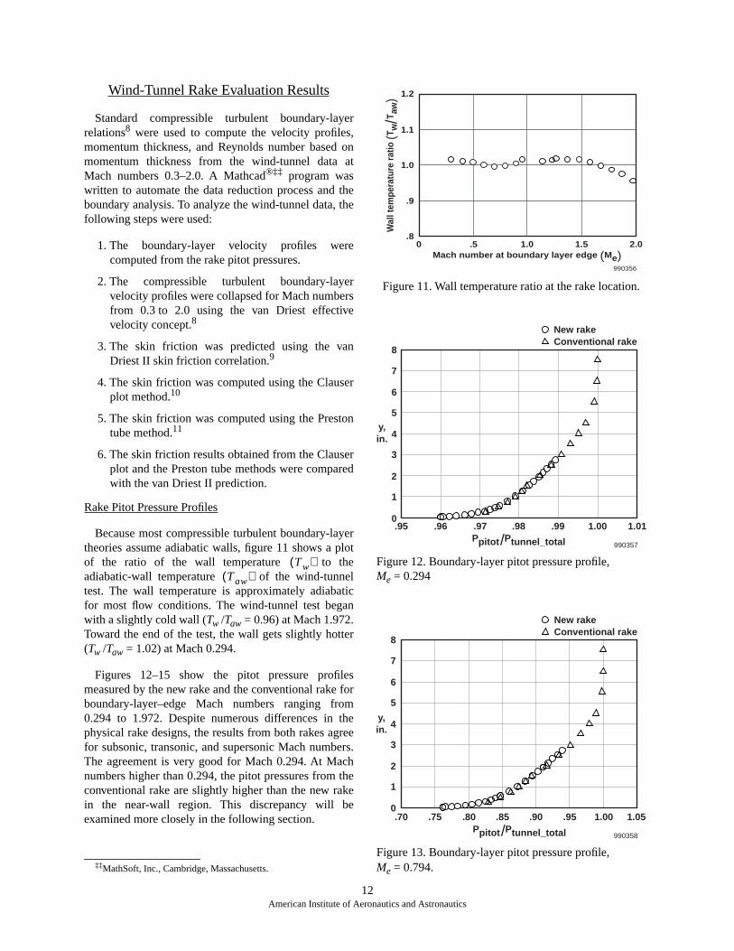
Because most compressible turbulent boundary-layertheories assume adiabatic walls, figure 11 shows a plotof the ratio of the wall temperature to theadiabatic-wall temperature of the wind-tunneltest. The wall temperature is approximately adiabaticfor most flow conditions. The wind-tunnel test beganwith a slightly cold wall (Tw /Taw = 0.96) at Mach 1.972.Toward the end of the test, the wall gets slightly hotter(Tw /Taw = 1.02) at Mach 0.294.
Figures 12–15 show the pitot pressure profilesmeasured by the new rake and the conventional rake forboundary-layer–edge Mach numbers ranging from0.294 to 1.972. Despite numerous differences in thephysical rake designs, the results from both rakes agreefor subsonic, transonic, and supersonic Mach numbers.The agreement is very good for Mach 0.294. At Machnumbers higher than 0.294, the pitot pressures from theconventional rake are slightly higher than the new rakein the near-wall region. This discrepancy will beexamined more closely in the following section.
Figure 11. Wall temperature ratio at the rake location
Figure 12. Boundary-layer pitot pressure profile, Me = 0.294
Figure 13. Boundary-layer pitot pressure profile, Me = 0.794.‡‡MathSoft, Inc., Cambridge, Massachusetts.
Tw( )Taw( )
Wal
l tem
pera
ture
rat
io (T
w/T
aw) 1.2
1.1
1.0
.9
.80 .5
990356
1.0Mach number at boundary layer edge (Me)
1.5 2.0
y,in.
8
.95
990357
7
6
5
4
3
2
1
0.96 .97 .98
Ppitot/Ptunnel_total
.99 1.00 1.01
New rakeConventional rake
y,in.
8
7
6
5
4
3
2
1
0.70
990358
.75 .80 .85 .90 .95 1.00 1.05Ppitot/Ptunnel_total
New rakeConventional rake
12American Institute of Aeronautics and Astronautics
:
dew
dthesgerrsthey
er
htt
gh1es
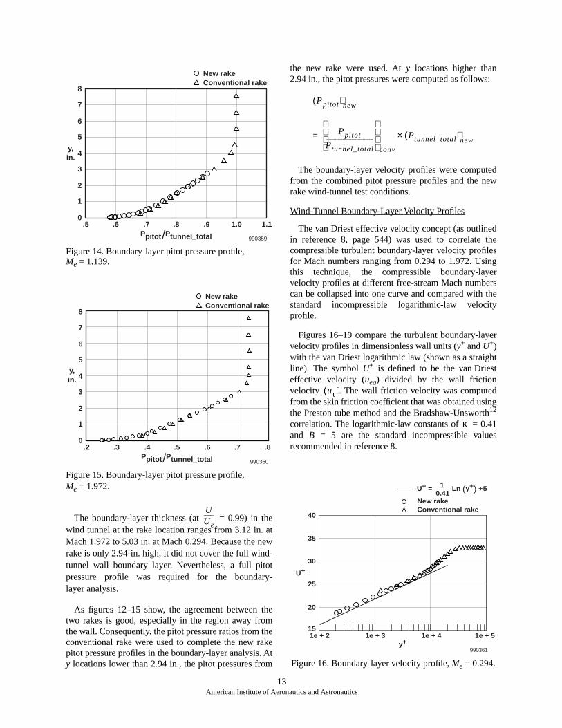
Figure 14. Boundary-layer pitot pressure profile,Me = 1.139.
Figure 15. Boundary-layer pitot pressure profile,Me = 1.972.
The boundary-layer thickness (at = 0.99) in thewind tunnel at the rake location ranges from 3.12 in. atMach 1.972 to 5.03 in. at Mach 0.294. Because the newrake is only 2.94-in. high, it did not cover the full wind-tunnel wall boundary layer. Nevertheless, a full pitotpressure profile was required for the boundary-layer analysis.
As figures 12–15 show, the agreement between thetwo rakes is good, especially in the region away fromthe wall. Consequently, the pitot pressure ratios from theconventional rake were used to complete the new rakepitot pressure profiles in the boundary-layer analysis. Aty locations lower than 2.94 in., the pitot pressures from
the new rake were used. At y locations higher than2.94 in., the pitot pressures were computed as follows
The boundary-layer velocity profiles were computefrom the combined pitot pressure profiles and the nrake wind-tunnel test conditions.
Wind-Tunnel Boundary-Layer Velocity Profiles
The van Driest effective velocity concept (as outlinein reference 8, page 544) was used to correlate compressible turbulent boundary-layer velocity profilefor Mach numbers ranging from 0.294 to 1.972. Usinthis technique, the compressible boundary-layvelocity profiles at different free-stream Mach numbecan be collapsed into one curve and compared with standard incompressible logarithmic-law velocitprofile.
Figures 16–19 compare the turbulent boundary-layvelocity profiles in dimensionless wall units (y+ and U+)with the van Driest logarithmic law (shown as a straigline). The symbol U+ is defined to be the van Drieseffective velocity (ueq) divided by the wall frictionvelocity . The wall friction velocity was computedfrom the skin friction coefficient that was obtained usinthe Preston tube method and the Bradshaw-Unswort12
correlation. The logarithmic-law constants of = 0.4and B = 5 are the standard incompressible valurecommended in reference 8.
Figure 16. Boundary-layer velocity profile, Me = 0.294.
y,in.
8
7
6
5
4
3
2
1
0.5
990359
.6 .7 .8 .9 1.0 1.1Ppitot/Ptunnel_total
New rakeConventional rake
y,in.
8
7
6
5
4
3
2
1
0.2
990360
.3 .4 .5 .6 .7 .8Ppitot/Ptunnel_total
New rakeConventional rake
UUe------
Ppitot( )new
Ppitot
Ptunnel_total-------------------------------
conv
Ptunnel_total( )new
×=
uτ( )
κ
U+
40
35
30
25
20
151e + 2 1e + 3 1e + 4 1e + 5
990361y+
New rakeConventional rake
U+ = 1 Ln (y+) +50.41
13American Institute of Aeronautics and Astronautics

reheheheewin
allta.rtisre
hetheew thekeineign
e
t
te
ch
Figure 17. Boundary-layer velocity profile, Me = 0.794.
Figure 18. Boundary-layer velocity profile, Me = 1.139.
The boundary-layer velocity profiles are seen to havethe standard logarithmic profile for all Mach numbers.Although the slopes of the data in the linearlogarithmic-law region match the van Driest logarithmiclaw well, U+ values from both of the rakes areapproximately 2.3–4.5 percent greater than thevan Driest logarithmic-law line.
The data points from the new rake lie on a straightline in the logarithmic-law region. The slope of the newrake data also matches the slope of the standardlogarithmic-law line. These observations give strongsupport that the new rake probes, including the ones
closest to the wall, indicated the correct total pressuvalues. The new rake provides good resolution of tlogarithmic region, and the data blend smoothly into tboundary-layer–wake region. The first data point off twall has a y+ value of approximately 200 to 300. Thlarge number of data points in the linear logarithmic-laregion is helpful for calculating the boundary-layer skfriction with the Clauser plot method.
Figure 19. Boundary-layer velocity profile, Me = 1.972.
The conventional rake data points closest to the ware noticeably higher than the new, curved rake daAdditionally, the conventional rake data points depafrom the slope of the standard logarithmic-law line. Thdiscrepancy is caused by the high total pressuindications by the conventional rake observed in tRake Pitot Pressure Profiles section. Because conventional rake uses larger pitot probes than the nrake does and the total pressure readings are towardhigh side, the first few probes of the conventional ramight be susceptible to the problem of probe centerldisplacement effect mentioned in the New Rake Dessection.
Skin Friction Results
The skin friction values were calculated using thfollowing four different methods:
• The Clauser plot method with the van Drieslogarithmic law. The van Driest logarithmic lawprovides a convenient way to estimate the flat-plaskin friction.
• The Clauser plot method with the Fenter-Stalmalogarithmic law.10
U+
40
35
30
25
20
151e + 2 1e + 3 1e + 4 1e + 5
990362y+
New rakeConventional rake
U+ = 1 Ln (y+) +50.41
U+
40
35
30
25
20
151e + 2 1e + 3 1e + 4 1e + 5
990363y+
New rakeConventional rake
U+ = 1 Ln (y+) +50.41
U+
40
35
30
25
20
151e + 2 1e + 3 1e + 4 1e + 5
990364y+
New rakeConventional rake
U+ = 1 Ln (y+) +50.41
14American Institute of Aeronautics and Astronautics

n-
ldsnten.
tum
ith±5ofhe
chithithan
• The Preston tube method with the Bradshaw-Unsworth calibration equation.12
• The Preston tube method with the Allen calibrationequation.11
The Clauser plot methods use rake data, and the Prestontube methods use Preston tube data.
The Clauser plot method fits the measured turbulentboundary-layer velocity profile to a compressiblelogarithmic law to get the skin friction value. Twodifferent logarithmic laws were used, the van Driest andthe Fenter-Stalmach logarithmic laws.
The Preston tube method (as outlined in reference 11)was used with the Bradshaw-Unsworth and the Allencalibration equations. These methods have been found11
to provide the best correlations for compressibleturbulent boundary layers.
Four different values of skin friction were computedfrom the wind-tunnel data using the appropriatetheories. These values then were transformed into theincompressible plane using the van Driest II correlation
and compared with the incompressible KarmaSchoenherr correlation as described in reference 9.
Figure 20 shows a plot of the results. The Reynonumber and the skin friction coefficient have beetransformed into the incompressible plane to facilitacomparison with the Karman-Schoenherr correlatioThe transformed Reynolds number based on momenthickness is approximately 7.5 × 10⁴ for Mach 2.0 flow,then increases to a maximum of 1.5 × 10⁵ for Mach 0.7flow before decreasing to approximately 8 × 10⁴ forMach 0.3 flow.
The majority of the results can be seen to agree wthe Karman-Schoenherr correlation to approximately percent, which is within the expected accuracy current skin friction theories and the uncertainties of tpast data used to correlate these theories.9 In general,the Clauser plot method used with the Fenter-Stalmalogarithmic law and the Preston tube method used wthe Bradshaw-Unsworth equation correlate better weach other and with the Karman-Schoenherr theory thother methods do.
15American Institute of Aeronautics and Astronautics
Figure 20. Skin friction coefficient distribution.
Cf
2.0e + 4
990365Reθ
Karman-Schoenherr Correlation+ 5% Karman-SchoenherrClauser plot method with van Driest log lawClauser plot method with Fenter-Stalmach log lawPreston tube method with Bradshaw-Unsworth equationPreston tube method with Allen equation
.0030
.0025
.0020
.0015
.00106.0e + 4 1.0e + 5 1.4e + 5 1.8e + 5
–

in
d
ic
e,es
”,
nnnic
l
-
nin
Conclusion
The design, fabrication, and wind-tunnel testing of anew, curved, boundary-layer rake have been described.This new boundary-layer rake will be used inF-15B/Flight Test Fixture flight research projects thatrequire detailed surveys of the turbulent boundary layer.A design feature unique to this rake is its curved rakebody, which allows pitot tubes to be clustered moredensely in the near-wall region than conventional rakesallow.
The new rake was found to have good aerodynamicperformance. The wind-tunnel test of the rake wasconducted in the NASA Glenn Research Center 8 × 6Supersonic Wind Tunnel at Mach numbers ranging from0 to 2. The pitot pressures from the new rake agreedwith data from a conventional rake over the range ofMach numbers tested. The boundary-layer profilescomputed from the rake data were shown to have thestandard logarithmic-law profile. Skin friction valuescomputed from the rake data using the Clauser plotmethods agreed with the Preston tube results and thevan Driest II compressible skin friction correlation toapproximately ±5 percent.
In addition to having good aerodynamic performance,the new rake design was found to be structurally rugged.Results from finite-element stress analysis of the newrake design showed very high factors of safety for bothwind-tunnel and flight conditions. The rake also passeda ground vibration test in which random vibrationmeasuring 12 g rms was applied for 20 min in each ofthe three normal directions.
References
1Richwine, David M., F-15B/Flight Test Fixture II: ATest Bed for Flight Research, NASA TM-4782, 1996.
2Clauser, Francis H., “Turbulent Boundary Layers inAdverse Pressure Gradients,” Journal of theAeronautical Sciences, Feb. 1954, pp. 91–108.
3Preston, J. H., “The Determination of Turbulent SkFriction by Means of Pitot Tubes,” Journal of the RoyalAeronautical Society, vol. 58, no. 518, Feb. 1954,pp. 109–121.
4Gracey, William, Measurement of Aircraft Speed anAltitude, NASA RP-1046, 1980.
5Grosser, Wendy I., Factors Influencing Pitot ProbeCenterline Displacement in a Turbulent SupersonBoundary Layer, NASA TM-107341, 1996.
6Gettelman, Clarence C., and Lloyd N. Kraus“Considerations Entering into the Selection of Probfor Pressure Measurement in Jet Engines,” Proceedingsof the Instrument Society of America, vol. 7, 1952,pp. 134–137.
7Allen, Jerry M., “Critical Preston-Tube Sizes,Journal of Aircraft, vol. 7, no. 3, May–June 1970pp. 285-287.
8White, Frank M., Viscous Fluid Flow, 2nd ed.,McGraw-Hill, Inc., Boston, Massachusetts, 1991.
9Hopkins, Edward J., and Mamoru Inouye, “AEvaluation of Theories for Predicting Turbulent SkiFriction and Heat Transfer on Flat Plates at Supersoand Hypersonic Mach Numbers,” AIAA Journal, vol. 9,no. 6, June 1971, pp. 993–1003.
10Allen, Jerry M. and Dorothy H. Tudor, Charts forInterpolation of Local Skin Friction From ExperimentaTurbulent Velocity Profiles, NASA SP-3048, 1969.
11Allen, Jerry M., Reevaluation of CompressibleFlow Preston Tube Calibrations, NASA TM X-3488,1977.
12Bradshaw, P. and K. Unsworth, “Comment oEvaluation of Preston Tube Calibration Equations Supersonic Flow,” AIAA Journal, vol. 12, no. 9,Sep. 1974, pp. 1293–1295.
16American Institute of Aeronautics and Astronautics
REPORT DOCUMENTATION PAGE Form ApprovedOMB No. 0704-0188
Public reporting burden for this collection of information is estimated to average 1 hour per response, including the time for reviewing instructions, searching existing data sources, gathering andmaintaining the data needed, and completing and reviewing the collection of information. Send comments regarding this burden estimate or any other aspect of this collection of information,including suggestions for reducing this burden, to Washington Headquarters Services, Directorate for Information Operations and Reports, 1215 Jefferson Davis Highway, Suite 1204, Arlington,VA 22202-4302, and to the Office of Management and Budget, Paperwork Reduction Project (0704-0188), Washington, DC 20503.
1. AGENCY USE ONLY (Leave blank) 2. REPORT DATE 3. REPORT TYPE AND DATES COVERED
4. TITLE AND SUBTITLE 5. FUNDING NUMBERS
6. AUTHOR(S)
8. PERFORMING ORGANIZATION REPORT NUMBER
7. PERFORMING ORGANIZATION NAME(S) AND ADDRESS(ES)
9. SPONSORING/MONITORING AGENCY NAME(S) AND ADDRESS(ES) 10. SPONSORING/MONITORING AGENCY REPORT NUMBER
11. SUPPLEMENTARY NOTES
12a. DISTRIBUTION/AVAILABILITY STATEMENT 12b. DISTRIBUTION CODE
13. ABSTRACT (Maximum 200 words)
14. SUBJECT TERMS 15. NUMBER OF PAGES
16. PRICE CODE
17. SECURITY CLASSIFICATION OF REPORT
18. SECURITY CLASSIFICATION OF THIS PAGE
19. SECURITY CLASSIFICATION OF ABSTRACT
20. LIMITATION OF ABSTRACT
NSN 7540-01-280-5500 Standard Form 298 (Rev. 2-89)Prescribed by ANSI Std. Z39-18298-102
Design and Evaluation of a New Boundary-Layer Rake for Flight Testing
WU 529-50-04-T2-RR-00-000
Trong T. Bui, David L. Oates, and Jose C. Gonsalez
NASA Dryden Flight Research CenterP.O. Box 273Edwards, California 93523-0273
H-2392
National Aeronautics and Space AdministrationWashington, DC 20546-0001 NASA/TM-2000-209014
A new boundary-layer rake has been designed and built for flight testing on the NASA Dryden Flight ResearchCenter F-15B/Flight Test Fixture. A feature unique to this rake is its curved body, which allows pitot tubes tobe more densely clustered in the near-wall region than conventional rakes allow. This curved rake design has acomplex three-dimensional shape that requires innovative solid-modeling and machining techniques. Finite-element stress analysis of the new design shows high factors of safety. The rake has passed a ground test inwhich random vibration measuring 12 g rms was applied for 20 min in each of the three normal directions.Aerodynamic evaluation of the rake has been conducted in the NASA Glenn Research Center 8 × 6 SupersonicWind Tunnel at Mach 0–2. The pitot pressures from the new rake agree with conventional rake data over therange of Mach numbers tested. The boundary-layer profiles computed from the rake data have been shown tohave the standard logarithmic-law profile. Skin friction values computed from the rake data using the Clauserplot method agree with the Preston tube results and the van Driest II compressible skin friction correlation toapproximately ±5 percent.
Boundary layer, Compressible flows, Flight testing, Pitot pressure rake,Skin friction
A03
22
Unclassified Unclassified Unclassified Unlimited
January 2000 Technical Memorandum
Presented at 38th AIAA Aerospace Sciences Conference, Reno, Nevada, January 10–13, 2000,AIAA-2000-0503. Trong T. Bui and David L. Oates of NASA Dryden Flight Research Center; Jose C.Gonsalez, Dynacs Engineering Co., Inc., Brookpark, Ohio.
Unclassified—UnlimitedSubject Category 02, 34Availability: NASA CASI (301) 621-0390This report is available at http://www.dfrc.nasa.gov/DTRS/