Electrodynamics Electromotive Force Electromagnetic Induction Maxwell’s Equations.

REVIEW OF SCIENTIFIC INSTRUMENTS VOLUME 70. NUMBER 6 JUNE 1999
Design and evaluation of a low thermal electromotive force guardedscanner for resistance measurements
Dean G. JarrettElectricityDivision,NatioruzlInstituteof Standardsand Technology,U.S.Departmentof Commerce,TechnologyAdministration,Gaithersburg,Maryland20899-8112
James A. Marshall and Thomas A. MarshallDataProof,1177SouthDe AnzaBoulevard,San Jose,California95129
Ronald F. DziubaElectricityDivision,NatioruzlInstituteof Standardsand Technology,U.S.Departmentof Commerce,TechnologyAdministration,Gaithersburg,Maryland20899-8112
(Received 14 December 1998; accepted for publication 18 February 1999)
The design and testing of a low thermal electromotive force guarded scanner, developed to providecompletely guarded switching when used with actively guarded resistance bridge networks, isdescribed. The design provides a continuous guard circuit trace on the scanner circuit boards thatsurrounds the relay contacts and protects the measurement circuit from leakages to ground.Modification to the circuit boards and relays of the guarded scanner are explained. Several testswere developed to evaluate the guarding effectiveness, including isolating sections of the guardcircuit to create a potential drop between the main and guard circuits. Calibration of standardresistors using the guarded scanner has shown relative differences less than 1X 10⁻⁶, 30X 10-6,and 150X 10-6 for measurements made with and without the guarded scanner at nominal resistancesof 1, 10, and 100 on, respectively. The substitution method was used to significantly reduce therelative differences between channels to less than 0.5X 10⁻⁶, 3X 10⁻⁶, and 30X 10-6 for nominalresistances of I, 10, and 100 on, respectively. Applications for the guarded scanner in automateddirect current measurement systems are presented. [S0034-6748(99)01306-4]
I. INTRODUCTION
. With the automation of measurement systems used tocalibrate standard resistors at NIST in the 1980's and 1990'scame the need for automating the connection of standardresistors to measurement systems. Automation improves thequality of the measurement process by eliminating operatorbias, provides a controlled repetitive algorithm for data col-lection, and permits data collection during nonworking hourswhen electrical and mechanical noise is at a minimum.I
Type B standard uncertainties attributed to leakage cur-rents flowing to ground have been reduced in many of theresistance measurement systems at NIST by the use of guardnetworks? Without also guarding the switching of resistors,leakage errors can degrade the accuracy of resistance mea-surements, especially at resistances ~ 100 kn. One approachto solving the switching problem is a programmable, guardedcoaxial panel3 to which connections are made using a three-axis positioning system to plug coaxial connectors into oneanother. A second approach, described here, is to design thecircuit boards and relays of a low thermal electromotiveforce (emf) scanner so that the measurement or main circuitpath is completely enclosed in a guard circuit. Driving theguard circuit at the same potential as the main circuit in-creases the effective resistance4of the insulation between themain and guard circuits, and very little leakage current isable to flow between the measurement and guard circuits.
Leakage currents that flow to ground potential from theguard circuit have negligible effect on the measurement cir-cuit.
Through a collaborative effort, Data Proofs and NISTresearchers have developed and evaluated a low thermal-emfguarded scanner that can be used in automated resistancebridges over the range from 100 n to 100 on without add-ing any appreciable uncertainty to that of the measurementprocess. The techniques used to guard the low thermal-emfscanner, including the redesign of the latching relays andmodifications to the printed circuit boards, are presentedalong with procedures used to evaluate the effectiveness ofthe guard circuit. Results of the evaluation are reported andseveral applications for a guarded scanner are discussed.
II. BACKGROUND
Low thermal-emf scanners have been used at NIST suc-cessfully in automating measurements over the range 100 nto 1 Mn with expanded uncertainties from 0.5X 10⁻⁶ to 3X 10⁻⁶, respectively. The largest source of type B standarduncertainty at the 100 kn and 1 Mn levels is leakages toground. Guarding the scanners and the resistor junctions inthe NIST-built unbalanced bridge2 would reduce the ex-panded uncertainties at resistance levels of 100 kfl andabove. Automation of guarded NIST measurement systemsat 10 Mfl and above6 would also benefit from the develop-
2866
Rev. Sei. Instrum., Vol. 70, No.6, June 1999
ment of a guarded scanner. The approach taken was to de-sign a second generation scanner that would provide guard-ing of the measurement circuit while maintaining the lowthermal-emf and low noise characteristics that make the useof these scanners in automated measurement systems suc-cessful.
By designing a guard circuit that would drive the coaxialshields at the same potentials as the inner conductors of themain circuit, the effective resistance of the insulation can besignificantly increased to provide greater protection of themeasurement or main circuit from leakages to ground poten-tial. The effective resistance, Reffis defined as
Reff=RinsVS1(Vs- VG)'
where Rins is the resistance of the insulator, Vs is the maincircuit potential, and VG is the guard potential. As an ex-ample, matching the guard potential within 1% of the maincircuit potential will increase the effective resistance by 100times the actual resistance of the insulator.
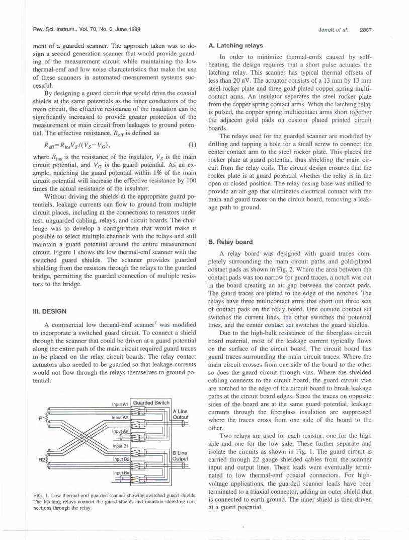
Without driving the shields at the appropriate guard po-tentials, leakage currents can flow to ground from multiplecircuit places, including at the connections to resistors undertest, unguarded cabling, relays, and circuit boards. The chal-lenge was to develop a configuration that would make itpossible to select multiple channels with the relays and stillmaintain a guard potential around the entire measurementcircuit. Figure 1 shows the low thermal-emf scanner with theswitched guard shields. The scanner provides guardedshielding from the resistors through the relays to the guardedbridge, permitting the guarded connection of multiple resis-tors to the bridge.
III. DESIGN
A commercial low thermal-emf scanner7 was modifiedto incorporate a switched guard circuit. To connect a shieldthrough the scanner that could be driven at a guard potentialalong the entire path of the main circuit required guard tracesto be placed on the relay circuit boards. The relay contactactuators also needed to be guarded so that leakage currentswould not flow through the relays themselves to ground po-tential.
R1
Input A 1 I Guarded SWitch" II
A LineOutout
InputBn
FIG. 1. Low thermal-emf guarded scanner showing switched guard shields.The latching relays connect the guard shields and maintain shielding con-nections through the relay.
Jarrett et al. 2867
(1)
A. Latching relays
In order to minimize thermal-emfs caused by self-heating, the design requires that a short pulse actuates thelatching relay. This scanner has typical thermal offsets ofless than 20 nV. The actuator consists of a 13 mm by 13 mmsteel rocker plate and three gold-plated copper spring multi-contact arms. An insulator separates the steel rocker platefrom the copper spring contact arms. When the latching relayis pulsed, the copper spring multicontact arms short togetherthe adjacent gold pads on custom plated printed circuitboards.
The relays used for the guarded scanner are modified bydrilling and tapping a hole for a small screw to connect thecenter contact arm to the steel rocker plate. This places therocker plate at guard potential, thus shielding the main cir-cuit from the relay coils. The circuit design ensures that therocker plate is at guard potential whether the relay is in theopen or closed position. The relay casing base was milled toprovide an air gap that eliminates electrical contact with themain and guard traces on the circuit board, removing a leak-age path to ground.
B. Relay board
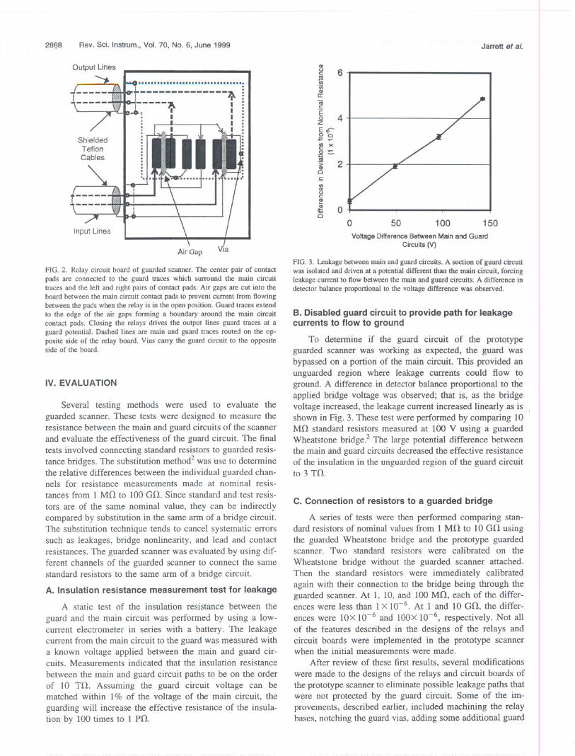
A relay board was designed with guard traces com-pletely surrounding the main circuit paths and gold-platedcontact pads as shown in Fig. 2. Where the area between thecontact pads was too narrow for guard traces, a notch was cutin the board creating an air gap between the contact pads.The guard traces are plated to the edge of the notches. Therelays have three multicontact arms that short out three setsof contact pads on the relay board. One outside contact setswitches the current lines, the other switches the potentiallines, and the center contact set switches the guard shields.
Due to the high-bulk resistance of the fiberglass circuitboard material, most of the leakage current typically flowson the surface of the circuit board. The circuit board hasguard traces surrounding the main circuit traces. Where themain circuit crosses from one side of the board to the otherso does the guard circuit through vias. Where the shieldedcabling connects to the circuit board, the guard circuit viasare notched to the edge of the circuit board to break leakagepaths at the circuit board edges. Since the traces on oppositesides of the board are at the same guard potential, leakagecurrents through the fiberglass insulation are suppressedwhere the traces cross from one side of the board to theother.
Two relays are used for each resistor, one for the highside and one for the low side. These further separate andisolate the circuits as shown in Fig. 1. The guard circuit iscarried through 22 gauge shielded cables from the scannerinput and output lines. These leads were eventually termi-nated to low thermal-emf coaxial connectors. For high-voltage applications, the guarded scanner leads have beenterminated to a triaxial connector, adding an outer shield thatis connected to earth ground. The inner shield is then drivenat a guard potential.
2868 Rev. Sei. Instrum., Vol. 70, No.6, June 1999
Output Lines
.. :~ :
~ I :. I I ::
~I :: I I :
¥. ' ,-:
I:. . .. . .. : .. ........-.4.
Air Gap Via
FIG. 2. Relay circuit board of guarded scanner. The center pair of contact
pads are connected to the guard traces which surround the main circuittraces and the left and right pairs of contact pads. Air gaps are cut into theboard between the main circuit contact pads to prevent current from flowingbetween the pads when the relay is in the open position. Guard traces extendto the edge of the air gaps forming a boundary around the main circuitcontact pads. Closing the relays drives the output lines guard traces at a
guard potential. Dashed lines are main and guard traces routed on the op-posite side of the relay board. Vias carry the guard circuit to the oppositeside of the board.
IV. EVALUATION
Several testing methods were used to evaluate theguarded scanner. These tests were designed to measure theresistance between the main and guard circuits of the scannerand evaluate the effectiveness of the guard circuit. The finaltests involved connecting standard resistors to guarded resis-tance bridges. The substitution method2 was use to determinethe relative differences between the individual guarded chan-nels for resistance measurements made at nominal resis-tances from I MO to 100 GO. Since standard and test resis-tors are of the same nominal value, they can be indirectlycompared by substitution in the same arm of a bridge circuit.The substitution technique tends to cancel systematic errorssuch as leakages, bridge nonlinearity, and lead and contactresistances. The guarded scanner was evaluated by using dif-ferent channels of the guarded scanner to connect the samestandard resistors to the same arm of a bridge circuit.
A. Insulation resistance measurement test for leakage
A static test of the insulation resistance between the
guard and the main circuit was performed by using a low-current electrometer in series with a battery. The leakagecurrent from the main circuit to the guard was measured witha known voltage applied between the main and guard cir-cuits. Measurements indicated that the insulation resistancebetween the main and guard circuit paths to be on the orderof 10 TO. Assuming the guard circuit voltage can bematched within I% of the voltage of the main circuit, theguarding will increase the effective resistance of the insula-tion by 100 times to 1 PO.
Jarrett et a/.
<II
g 6cv(jj.(jj<IIII:
(ijc
.~ 4zE <D-Ob.:::.....~ )(
.2::"1ii.~ 2CI.5(II<IIoC<II
~ 0;I:
CI 0 10050 150
Voltage Difference Between Main and GuardCircuits(V)
FIG. 3. Leakage between main and guard circuits. A section of guard circuitwas isolated and driven at a potential different than the main circuit, forcingleakage current to flow between the main and guard circuits. A difference indetector balance proportional to the voltage difference was observed.
B. Disabled guard circuit to provide path for leakagecurrents to flow to ground
To determine if the guard circuit of the prototypeguarded scanner was working as expected, the guard wasbypassed on a portion of the main circuit. This provided anunguarded region where leakage currents could flow toground. A difference in detector balance proportional to theapplied bridge voltage was observed; that is, as the bridgevoltage increased, the leakage current increased linearly as isshown in Fig. 3. These test were performed by comparing 10Mil standard resistors measured at 100 V using a guardedWheatstone bridge.2 The large potential difference betweenthe main and guard circuits decreased the effective resistanceof the insulation in the unguarded region of the guard circuitto 3 TO.
C.Connectionof resistors to a guarded bridge
A series of tests were then performed comparing stan-dard resistors of nominal values from 1 MO to lOGO usingthe guarded Wheatstone bridge and the prototype guardedscanner. Two standard resistors were calibrated on theWheatstone bridge without the guarded scanner attached.Then the standard resistors were immediately calibratedagain with their connection to the bridge being through theguarded scanner. At 1, 10, and 100 MO, each of the differ-ences were less than 1X 10- 6. At 1 and lOGO, the differ-ences were lOX 10-6 and 100X 10-6, respectively. Not allof the features described in the designs of the relays andcircuit boards were implemented in the prototype scannerwhen the initial measurements were made.
After review of these first results, several modificationswere made to the designs of the relays and circuit boards ofthe prototype scanner to eliminate possible leakage paths thatwere not protected by the guard circuit. Some of the im-provements, described earlier, included machining the relaybases, notching the guard vias, adding some additional guard

Rev. Sei. Instrum.,Vol.70, No.6, June 1999
1000
. . . . . . .
"?-o
.100 Gohm
.10 Gohm.to1Gohm
. . . . . ..;. 100CII
8c:~CD:tCI
~ 10~Q)a:
. . .to· ... .to ... ... ... ... .
1...
o 4 8Channel 12
FIG. 4. Relative differences of calibration of standard resistors from I to
100 Go. made using the guarded scanner. Differences between calibrationsmade with resistors directly connected to measurement system and connec-
tion made through each channel of the guarded scanner.
traces, and increasing the wire size. Further measurementswere made using a new guarded active-arm bridge6 whichwas not available when the prototype scanner was first evalu-ated at NIST. Like the guarded Wheatstone bridge, theactive-arm bridge substitutes standard and unknown resis-tances into one of the guarded bridge arms. Since the active-arm bridge is automated, more data could be collected in atimely manner and measurements could be made at decaderesistances above lOGo'.
D. Results
Measurements were not made at 1, 10, and 100 Mo',with the active-arm bridge since previous measurementsmade with the Wheatstone bridge detennined that differ-ences between channels were less than 1X 10- 6 for resis-tances ~loo Mo'. Figure 4 shows the relative differencebetween measurements made with the resistors directly con-nected to the active-arm bridge and the resistors connected tothe active-arm bridge with the guarded scanner for 1, 10, and100 Go' standard resistors. Adding the guarded scanner tothe system contributes 2X 10⁻⁶, 30X 10-6, and 150X 10-6offsets from the direct measurement of 1, 10, and 100 Go'standard resistors, respectively, demonstrating a factor of 3improvement over the prototype scanner results reported inthe previous section. The offsets are consistent from channelto channel as shown in Fig. 5 where the difference from themean of all 12 channels has been graphed. The standarddeviation of the measurements reported in Figs. 4 and 5 are0.3X 10-6, 1.5X 10⁻⁶, and 15X 10-6 for 1,10, and 100 Go'decades of resistance, respectively. The substitution methodcancels the large offsets shown in Fig. 4 by allowing theindirect comparison of standards, check standards, and un-known resistors. A type A uncertainty of 0.3X 10⁻⁶, 1.5X 10⁻⁶, and 15X 10-6 would need to be added to the uncer-taintybudgetof the measurementsystemfor measurements.at 1, 10, and 100 Go', respectively. Combined relative stan-dard uncertainties for the NIST active-arm bridge withoutthe guarded scanner are 5.9X 10⁻⁶, 12.6X10⁻⁶, and 51.6
Jarrett et al. 286Q
35
30
25
-20II>
~ 15x~ 10
~ 5c:
~ 0u~ -5OJ
~ -10
-15
-20
-25
o 4 8 12Channel
FIG. 5. Relative differences between channels shows deviation between
individual channels. The substitution technique may be used for many mea-surements up to 10 Go. without significantly increasing the combined un-certainty of the measurement.
X 10-6 for measurements at 1, 10,and 100 Go', respectively.Adding the guarded scanner to the active-arm bridge in-creases the combined relative standard uncertainty at 100Go, to 53.7X 10⁻⁶, combined relative standard uncertaintiesat 1 and lOGO, remain unchanged.
v. APPLICATIONS IN MEASUREMENT SYSTEMS
Low thermal-emf scanners have been used in dc metrol-ogy applications such as standard cell and standard resistormeasurements, and guarded scanners may improve the un-certainty of these measurements. Guarded scanners can beused in applications where shielded or guarded multiple stan-dards or components are connected to a measurement sys-tem. Automated switching not only relieves an operator oftedious measurements but also permits multiple parametercharacterization of multiple units under test. In the case ofstandard resistors, this facilitates the determination of volt-age, temperature, humidity, and pressure coefficients for sev-eral resistors and allows selection of the best ones for use asstandards.
A. Automated active-arm bridges
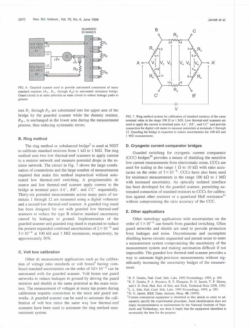
Guarded high-resistance bridges that use programmabledc sources6.Sto obtain a bridge balance can use the guardedscanner to connect standards, check standards, and unknownresistors to the bridge. Such a system was used to evaluatethe guarded scanner as described in the previous section.Combined expanded uncertainties for these bridges over therange 10 Mo' to 100 GO range from 4 X 10⁻⁶ to 56X 10-6, respectively. Measurements up to 1 Go' can bemade using the guarded scanner without significant increasein the combined expanded uncertainties. The same can beachieved at 10 and 100 GO, provided the substitutionmethod is used to cancel relative differences caused by leak-age and stray capacitance in the scanner. Figure 6 shows theguarded scanner connecting standard, check standard, andunknown resistors to an automated resistance bridge. Resis-
. .100Gohm. 10Gotm&1Gohm
-.- . .. ! . .. . .. - .. - ... . .. .
. .
287~ Rev. Sei. Instrum., Vol. 70, No.6, June 1999
GUARDEDSCANNER
R1
R2
RN
FIG. 6. Guarded scanner used to provide automated connection of manystandard resistors (R I' R2' through RN) to automated resistance bridge.Guard circuit is at same potential as main circuit to reduce leakage paths toground.
tors R] through R N are substituted into the upper arm of thebridge by the guarded scanner while the dummy resistor,R D' is unchanged in the lower arm during the measurementprocess, thus reducing systematic errors.
B. Ring method
The ring method or unbalanced bridge2 is used at NISTto calibrate standard resistors from 1 kO to 1 MO. The ringmethod uses two low thermal-emf scanners to apply currentto a resistor network and measure potential drops in the re-sistor network. The circuit in Fig. 7 shows the large combi-nation of connections and the large number of measurementsrequired that make this method impractical without auto-mated low thermal-emf switching. A programmable dcsource and low thermal-emf scanner apply current to thebridge at terminal pairs AA I, BB', and CC' sequentially.Thirty-six potential measurements across many pairs of ter-minals 1 through 12 are measured using a digital voltmeterand a second low thermal-emf scanner. A guarded ring standhas been designed for use with guarded low thermal-emfscanners to reduce the type B relative standard uncertaintycaused by leakages to ground. Implementation of theguarded scanner and guarded ring stand is expected to reducethe present expanded combined uncertainties of 2 X 10⁻⁶ and3 X 10-6 at 100 kO and 1 MO resistances, respectively, byapproximately50%.
C. Volt box calibration
Other dc measurement applications such as the calibra-tion of voltage ratio standards or volt boxes9 having com-bined standard uncertainties on the order of lOX 10-6 can beautomated with the guarded scanner. Volt boxes use guardnetworks to reduce leakages to ground by driving the guardresistors and shields at the same potential as the main resis-tors. The measurement of voltages at many tap points duringcalibration requires connection to the main and guard net-works. A guarded scanner can be used to automate the cali-bration of volt box ratios the same way low thermal-emfscanners have been used to automate the ring method mea-surement system.
Jarrett at al.
B c
A AI
cl B'
IIV
FIG. 7. Ring method system for calibration of standard resistors of the samenominal value in the range 100 0 to 1 MO. Low thermal-emf scanners are
used to apply the current to terminal pairs AA' , BB', and CC' and provideconnection for digital volt meter to measure potentials at terminals 1 through
12. Guarding the bridge is expected to reduce uncertainties for 100 kO and1 MO measurements.
D. Cryogeniccurrentcomparatorbridges
Guarded switching for cryogenic current comparator(CCC) bridges10provides a means of shielding the sensitivelow current measurements from electrostatic noise. CCCs areused for scaling in the range 1 0 to 10 kO with ratio accu-racies on the order of 5 X 10⁻⁹. CCCs have also been usedfor resistance measurements in the range 100 kO to 1 MOwith increased uncertainty. An optically isolated interfacehas been developed for the guarded scanner, permitting au-tomated connection of standard resistors to CCCs for calibra-tion against other resistors or a quantized Hall resistance]]withoutcompromisingthe ratioaccuracyof the CCC.
E. Other applications
Other metrology applications with uncertainties on theorder of 1X 10⁻⁶ can benefit from guarded switching. Oftenguard networks and shields are used to provide protectionfrom leakages and noise. Discontinuous and incompleteshielding leaves circuits unguarded and permit noise to entera measurement system compromising the uncertainty of themeasurement system and making automation difficult if notimpossible. The guarded low thermal-emf scanner provides away to automate high-precision measurements without sig-nificantly increasing the uncertainty budget of the measure-ment.
I R. F. Dziuba, Natl. Conf. Stds. Labs. 1995 Proceedings, 1995, p. 189.2R. F. Dziuba, P. A. Boynton, R. E. Elmquist, D. G. Jarrett, T. P. Moore,
and J. D. Neal, Natl. Inst. of Stds. and Tech. Technical Note 1298, 1992.
3L. L. Kile, Natl. Conf. Stds. Labs. 1995 Proceedings, 1995, p. 285.4D. G. Jarrett, IEEE Trans. Instrum. Meas. 48, (1999).
5Certain commercial equipment is identified in this article in order to ad-equately specify the experimental procedure. Such identification does notimply recommendation or endorsement by the National Institute of Stan-dards and Technology, nor does it imply that the equipment identified isnecessarily the best for the purpose.

Rev. Sei. Instrum., Vol. 70, No.6, June 1999 Jarrett et al. 28?1
6D. G. Jarrett,IEEE Trans Instrom. Meas. 46. 325 (1997).7J. A. Marshall. Meas. Sci. Conf. Proceedings. 1987. p. VIA-I.8L. C. A. Henderson. J. Phys. E 20. 492 (1987).9B. L. Dunfee. J. Res. Nat!. Bur. Stand.. Sect. C 67C. 1 (1963).
lOR.F. Dziubaand R. E. Elmquist. IEEE Trans Instrum. Meas.42. 126(1993).
\I M. E. Cage.R. F. Dziuba,C. T. Van Degrift. andD. Y. Yu. IEEE Trans.Instrum.Meas.38. 263 (1989).