Design and Construction Standards...Design and Construction Standards Regulating the Construction...
390
Design and Construction Standards Regulating the Construction and Expansion of Central Water and Sewer Systems within The County of Augusta, Virginia Augusta County Service Authority Augusta County Government Center Building Verona, Virginia May 3, 2016 Update September 1, 2016 Effective Date
Transcript of Design and Construction Standards...Design and Construction Standards Regulating the Construction...

Design and Construction Standards
Regulating the Construction and Expansion of Central Water and Sewer Systems within
The County of Augusta, Virginia
Augusta County Service Authority Augusta County Government Center Building
Verona, Virginia May 3, 2016 Update
September 1, 2016 Effective Date
2 of 52 ACSA Design Standards
A. Introduction 7
1. Purpose 7
2. Authority 7
3. Contact 8
4. Plan Submittal Process 8
B. Design Standards 11
1. General 11
a. Future Extensions 11 b. Design Calculations 11 c. Easements and Property 12 d. Separation of Utilities 14 e. Plan Sheet Preparation & Drafting Standards 14
1) General 14 2) Safety 15 3) Specific Plan Sheet Requirements 15 4) Minimum Size 18
f. Record Plans 19 g. Casing Pipe 19 a. Capacity 20
1) Design Calculations 20 b. Design Flow and Model Development 20
1) Fire Flow 22 2) Level of Service Standards 22 3) Domestic Demand 22 4) Future Demand 23
c. Pressure 23 d. Effective Storage 23 e. Pipe 23
1) Minimum Size 24 2) Surface Water Crossings 24 f. Appurtenances 24
1) Dead Ends 24 2) Valves 25 3) Hydrants 25 4) Service Laterals 26 5) Water Meters 27 6) Backflow Preventers 27
g. Booster Stations & Hydro-pneumatic Tanks 27 1) General Requirements 28 2) Capacity 28 3) Hydraulic Analysis 28 4) Pump Selection & Equipment 29 5) Power Requirements 29 6) Gauges and Meters 30 7) Controls & SCADA 30 8) Electrical 31 9) Lighting 31
3 of 52 ACSA Design Standards
10) Ventilation 31 11) Heating 32 12) Moisture Control 32 13) Building Design 32 14) Site Grading 32 15) Fencing 32 16) Access 32 17) Vandalism 32
h. Cross-Connection Control 33
3. Sewer 34
a. Gravity Sewers 34 1) General 34 2) Capacity 34 3) Alignment & Slope 35 4) Depth 37 5) Size 37 6) Sewer Connections 37 7) River or Stream Crossings and Pipe Installation in Marshy Areas 38
b. Manholes 39 1) General 39 2) Layout 39 3) Size 39 4) Frame and Cover 39 5) Inverts and Slope 40 6) Force Main Receiving Manholes 40 7) Drop Manholes 40 8) Doghouse Manhole 41
c. Force Mains & Pump Stations 41 1) General Requirements 41 2) System Design 41 3) Pump Stations 43 4) Force Mains 49
d. Rules and Regulations for Waste Water Discharge 51
4 of 52 ACSA Design Standards
C. Construction Specifications
Section 01110 - General Requirements
Section 01450 - Testing and Inspection Requirements
Section 01610 - Delivery, Storage and Handling
Section 02080 - Utility Pipe and Materials
Section 02085 - Valves and Cocks
Section 02200 - Site Construction for Pump Stations
Section 02317 - Excavation, Trenching, & Backfilling for Utilities
Section 02510 - Water Distribution
Section 02515 - Hydrants
Section 02530 - Sanitary Sewerage Systems
Section 02821 - Chain Link Fences and Gates Section 03310 - Insulated Concrete Forms Section 03400 - Precast Concrete Structures Section 04100 - Generic Block Building Construction (CMU) Section 06110 - Wood Framing and Construction ` Section 07210 - Building Insulation Section 07310 - Roofing Singles Section 07410 - Metal Roofing and Wall Panels Section 07415 - Metal Siding and Trim Section 07461 - Fiber Cement Siding and Trim Section 07600 - Gutter, Flashing, and Sheet Metal Section 08100 - Steel Doors and Frames Section 08700 - Finish Hardware Section 09910 - Exterior Painting
5 of 52 ACSA Design Standards
Section 09920 - Interior Painting
Section 11315 - Wastewater Pump Station
Section 13200 - Ground Storage Tank Potable Water
Section 16010 - Electrical Requirements for Pump Stations
Section 16210 - Electric Generator Section 16400 - Low Voltage Distribution Section 16500 - Lighting D. Standard Details
1. General
G-1 - Typical Sleeve Under Roadway G-2 - Typical Sleeve Under Railway G-3A - Typical Thrust Block Detail for Horizontal and Sag Vertical Details G-3B - Typical Thrust Block Detail for Horizontal and Sag Vertical Details (T
values) G-4A - Typical Thrust Block Detail Vertical Crest Anchors G-4B - Typical Thrust Block Detail Vertical Crest Anchors (b values) G-5 - Typical Restraint Detail For Slopes Over 20% G-6 - Typical Concrete Encasement G-7 - Typical Pavement Patch For Private Paved Roads
2. Sewer
S-1 - Typical Sewer Pipe Installation In Trench S-2 - Typical Residential Sewer Service Connection S-3 - Typical Sanitary Sewer Manhole S-4 - Typical Manhole Step S-5 - Typical Manhole With Drop Connection S-6 - Typical Manhole Plan View Showing Branch Tie-In & Invert Channeling S-7 - Typical Manhole Frame & Cover S-7A - Typical Water-Tight Manhole Frame & Cover S-8 - Manhole Ventilation
3. Water
W-1 - Typical Ductile Iron Pipe Installation and Bedding Requirements W-2 - Typical Fire Hydrant Installation W-3 - Typical Blow-Off or Blow Down Assemble W-4 - Typical Air Release Valve Installation
W-4A - Air Release Valve for Deep Installation W-5 - Typical Gate Valve Installation
W-6 - Typical Water Service Lateral Installation (5/8" - 1" Meters) W-7 - Typical Water Service Connection (5/8", 3/4" & 1" Meters)
W-7A - Double Residential Meter Detail (5/8" Only) W-8 - Typical Water Service Connection (1-1/2" & 2" Meters) W-9 - Typical Meter Vault for Connection 3" and Larger or DDCA
W-10 - Typical Restraining Device
6 of 52 ACSA Design Standards
APPENDICES 1. Standard Forms
See: http://www.acsawater.com/standards
a. Augusta County Submittal Checklist b. ACSA Application for Plan Review c. ACSA Fire Hydrant Flow Test Form d. ACSA Water Meter Sizing Form e. ACSA Preconstruction Meeting f. ACSA Reservation of Treatment Capacity Agreement – Payment in Full g. ACSA Reservation of Treatment Capacity Agreement – Partial Payment
2. Augusta County Fire Flow & Hydrant Standards
3. Rules and Regulations for Waste Water Discharge
7 of 52 ACSA Design Standards
A. Introduction
1. Purpose
a. The purpose of this publication is to state:
1) The design standards and construction specifications for the planning, design, construction, and connection of all public or intended to be public water and sewer utilities.
b. These standards and specifications have been developed for use by consultants, developers, and contractors who work on water and sewer utility projects within Augusta County and for ACSA personnel. The standards and specifications are not intended as a regulation, but should be followed for all projects involving review and approval through the Augusta County Service Authority which will establish a degree of uniformity for drawings and specifications and materials and equipment for all water and sewer utility projects.
2. Authority
a. The work described herein is under the jurisdiction of the Augusta County Service Authority hereinafter referred to as ACSA.
b. These policies, Design and Construction Standards, and associated rules and regulations, adopted by the ACSA in accordance with the Code of Augusta County, Virginia and the Virginia Water and Waste Authorities Act (Virginia Code § 15.2-5100 et seq.), are applicable to all existing and future water and sanitary sewerage facilities under or which will be under the jurisdiction of the ACSA. The Design and Construction Standards shall apply only to newly constructed facilities or repairs to or replacements or modification of existing facilities.
c. Consultants and contractors working on water and sewer utility projects should recognize the fact that State and Federal regulations must be satisfied on all projects. In the event that the ACSA Standards differ from State or Federal Requirements, the more restrictive standard shall be utilized.
d. Virginia Department of Health (VDH) review and approval for, booster stations, pre-treatment facilities, storage facilities, and water lines larger than 16 inches in diameter is required by the in accordance with section 12VAC5-590-300 of the Waterworks Regulations, in addition to the review and approval required by the ACSA. For gravity sewer projects with average day design flows over 40,000 gpd, pump stations/force mains to gravity sewers with average day design flows >2000 gpd, pump stations/force main to pressurized systems, and vacuum systems a Certificate to Construct (CTC) must be obtained from the Virginia Department of Environmental Quality (DEQ).
e. It is very difficult to generalize when addressing matters of engineering design without endangering the final product; therefore, consultants should strive for designs that show consideration of details presented herein. However, these details are secondary to good engineering judgment.
f. In addition, these policies, Design and Construction Standards, and associated rules and regulations are applicable to certain water and sewer mains and sub-
8 of 52 ACSA Design Standards
mains which are located on private property and are privately owned and maintained, and connect to or are intended to be connected to water and sewerage facilities owned and operated by the ACSA. The ACSA finds that the improper design, construction, and operation of such privately owned and maintained facilities have the potential (a) to result in violations, chargeable to the ACSA, of permits and applicable laws administered by the Commonwealth of Virginia, related to the proper operation of its treatment facilities, (b) to prevent or impede the ability of the ACSA to serve existing and future customers, and (c) to create avoidable and extraneous demands on the facilities of the ACSA, which demands would, in turn, result in a loss of economic efficiency in the provision of services to its customers. Based on the foregoing findings, and pursuant to authority under Virginia Code §§ 15.2-5114(2) and § 15.2-5137(A), these rules, regulations and Design and Construction Standards shall also apply to water and sewer mains and sub-mains extending onto private property that are connected to or are intended to be connected to water and sewerage facilities owned and operated by the ACSA. Such facilities on private property shall remain privately owned and maintained, but shall be designed, constructed, inspected, and operated in accordance with these rules, regulations and Design and Construction Standards.
As with facilities under or which will be under the jurisdiction of the ACSA, Design and Construction Standards shall apply only to those facilities on private property which are newly constructed or which are repaired, replaced or modified.
3. Contact
a. Inquiries for information or clarification of any item enclosed in this document should be directed to the Executive Director, Augusta County Service Authority, P. O. Box 859, Verona, VA 24482, 540-245-5670.
b. Additional information can be obtained on the ACSA website: http://www.acsawater.com/
c. Other County departments may be contacted for additional information:
1) Government Center Main Switchboard: 540-245-5600 http://www.co.augusta.va.us/ -- County of Augusta
2) Building Inspections: 540-245-5700 3) Community Development/Planning/Zoning: 540-245-5700 4) Parks and Recreation: 540-245-5727
4. Plan Submittal Process
a. General
All plans, regardless of plan type, are to be submitted to the Augusta County Community Development Department in accordance with Chapter 21 and Chapter 25 Article LXVII and latest versions of the ACSA Design and Construction Standards.
Submittal Packages submitted to the Community Development Department should include application, Augusta County Submittal Checklist located at www.acsawater.com, and any other applicable items as indicated by the Submittal Checklist.
9 of 52 ACSA Design Standards
Once plans are submitted, the Community Development Department routes said plans to all review agencies/departments for approval. The Service ACSA will have comments completed and returned to Community Development within 10 business days of the received date for Final Plats, Site Plans, and Erosion and Sediment Control Plans or 45 days for Construction plans. These time frames are the same for the first and subsequent submittals.
Once reviewed, the ACSA comments will be submitted through the Community Development Department Plan Review website for their distribution to other approval agencies and to applicant.
The ACSA reviews plans in the order they are received. The plan preparer is responsible for submitting plans at such a time that will provide adequate review time through the ACSA for meeting any deadlines. Subdivision and Utility Extension Plan approval shall be valid for 1 year. All other approvals shall coincide with Augusta County Community Development approval terms.
b. AUGUSTA COUNTY SERVICE AUTHORITY REQUIREMENTS An ACSA Application for Plan Review, the Augusta County Submittal Checklist located at www.acsawater.com, and other forms and submittals as required by the Submittal Checklist must be submitted with all types of plans.
Review of the plans will not commence until all necessary items in the checklist have been received by the ACSA. If submittal package is incomplete, it will be returned with a request for the required information. Plan review will not be performed until a complete submittal package is received by the ASCA.
All engineering plan review, inspection fees, and reserve capacity fees (if applicable) must be paid prior to plan approval. Plans shall adhere to the ACSA’s design and approved product policies.
If any plan is not approved, second and subsequent plans must be submitted to Community Development, with the same procedures as with the initial plan submittal.
Plans may require VDH and/or DEQ review. Plans shall be submitted to these agencies after ACSA review. Review and approval for all pump stations, pre-treatment facilities and sewer lines larger than 12” in diameter is required by DEQ in accordance with Section 9VAC25-790-60 of the Sewage Collection and Treatment Regulations, in addition to the review and approval required by the ACSA. Review and approval of booster stations, storage facilities and water lines larger than 16” in diameter is required by VDH in accordance with Section 12VAC5-590-300 of the Waterworks Regulations in addition to the review and approval required by the ACSA.
Copies of the completed applications for permits from other privately owned public utility providers, railroads, applicable environmental agencies, shall be provided to ACSA at the time of plan submittal. Developer shall also coordinate design and placement with any existing easement restrictions and
10 of 52 ACSA Design Standards
agreements required by the utility companies. New agreements/permits regarding shared easement areas or installation shall be reviewed and approved by the ACSA prior to plan approval.
For further information please reference Policy 10.6 “Plan Review and Project Acceptance for Water and Sewer Service.”
c. FEES REQUIRED FOR ACSA APPROVAL
The current fee schedule is available at www.acsawater.com or by calling the ACSA.
5. For information regarding application for water or sewer service, additional plan submittal and review requirements, reserved capacity, acceptance of new construction, and other policies, please see the ACSA Operation Procedures and Policy Manual (OPPM), latest edition. This manual may be reviewed at the ACSA offices, or viewed on-line at www.acsawater.com.
11 of 52 ACSA Design Standards
B. Design Standards (To be used in conjunction with Section C – Construction Specifications)
1. General
a. Future Extensions
Generally, the capacities of sanitary sewer lines and water lines should be designed for the estimated ultimate build out population of the service area being considered for development. Any known future development shall be considered as well.
The designer shall also estimate the ultimate build out population for the total sewer shed area. Future population densities should consider the Augusta County Comprehensive Plan, Zoning Ordinance, and Subdivision Ordinance as applicable. Based on the results of this estimate, the ACSA may participate in the project in accordance with the ACSA OPPM Policy No. 10.2 System Improvements.
The developer is required to design and construct his system, properly sized, to permit future extensions to be made. Elevation of the sewer system must be designed such that future extensions can serve the entire area which naturally drains towards the system. Stubouts and/or easements for water and/or sewer shall be provided to adjoining property lines where in conformance with the Augusta County Comprehensive Plan or as deemed appropriate by the ACSA to provide for future extension of the systems. Stubouts shall be provided beyond edge of pavements to allow for future extensions without damaging pavement.
b. Design Calculations
Calculations showing estimated water demand and sewer flow based on the criteria outlined in these standards shall be submitted for review with all plans that include public utilities. Calculations shall demonstrate that the existing utility infrastructure is capable of handling the demand of the proposed development. Otherwise the calculations shall identify the deficiencies and provide recommendations for improvement as part of the proposed development. During the design phase following Preliminary Plat approval, calculations shall be refined as follows. Resubmission of calculations during the design phase may be waived upon written approval of the ACSA’s Engineer.
All water line and sewer line extensions shall be accompanied by one set of hydraulic and capacity calculations respectively. Calculations should address such issues as available/required fire flow and domestic demand, pipe size and capacity, velocity, percent slope, etc. Additional guidelines and requirements for design are included in Section B.2. for Water, and Section B.3. for Sewer. Submission of calculations for minor extensions may be waived upon written approval of the ACSA’s Engineering Department.
12 of 52 ACSA Design Standards
Design calculations are also required to be submitted for other water/sewer facilities such as storage tanks, booster stations, sewage pump stations etc. in accordance with these Standards. However, VDH and/or DEQ review of these items is also required. Documentation shall be provided to the ACSA that VDH and/or DEQ approval has been obtained where required.
All submitted calculations shall be signed, sealed, and dated by a professional engineer or class B land surveyor licensed in the Commonwealth of Virginia, and shall be in accordance with the Virginia Department of Health (VDH) Waterworks Regulations and the Virginia Department of Environmental Quality (DEQ) Sewage Collection and Treatment (SCAT) Regulations.
c. Easements and Property
1) Permanent Water and/or Sewer Easements
Shall be required for all water and sewer lines and appurtenances except where installed within a publicly dedicated right-of-way. Where water and/or sewer lines are installed within the right-of-way, additional permanent easement width shall be provided to designate a minimum of 20 foot working space between the edge of pavement and the easement boundary. All easements shall have the right of ingress and egress fully provided for in the recorded deed. Easements shall be provided up to and including the water meter and/or sewer cleanout.
When public fire hydrants and other appurtenances are installed on private property, a permanent easement shall be provided 10 feet around the feature on all sides.
The minimum permanent easement width shall be fifteen (15) or twenty (20) feet dependent upon location of easement on the property. A total of twenty (20) feet of legal working space shall be provided over water or sewer lines (5 feet may be in dedicated road right of way) with an exclusive easement area of ten (10) feet of width centered on the pipeline. Joint permanent easements combining both water and sewer mains within a single permanent easement shall be a minimum of thirty (30) feet in width; a minimum of ten (10) feet shall be the required distance between the mains (measured from edge to edge of pipes) with a minimum of an additional ten (10) feet required from the centerline of each main to the permanent easement boundary. The 10 foot wide exclusive are over each pipe shall be maintained for each pipe.
No buildings, facilities, or structures shall be located on the surface of the land within permanent easement area. No other utilities, including telephone, cable, fiber optic, gas, electric and industrial pipes shall be constructed parallel to water and sewer utilities within the ten (10) foot wide exclusive easement area. No water shall be impounded within the permanent easement area without the prior written approval of the ACSA.
Land for dedicated facilities such as booster stations, pump stations, tanks, etc., shall be transferred to the ACSA by deed. The property shall be transferred at no cost to the ACSA with general title and English covenants. For water storage tanks, minimum lot size shall be 1 acre unless otherwise demonstrated that future maintenance and replacement/expansions can occur without further land acquisition. For water booster and sewer pump stations, adequate space shall be provided to permit maintenance equipment (temporary pumps and
13 of 52 ACSA Design Standards
maintenance equipment) to be on the site without being in the road right of way or on other private properties. For sewer pumping stations a 100 foot buffer around the station shall be provided where no structures will be located unless otherwise approved. (ref. Virginia Sewage Collection and Treatment Regulations - 9VAC25-790-120.D.1). Other facilities, such as treatment facilities, will be handled on a case by case basis as in addition to maintenance of operations, other buffer requirements in accordance with the DEQ SCAT Regulations may apply.
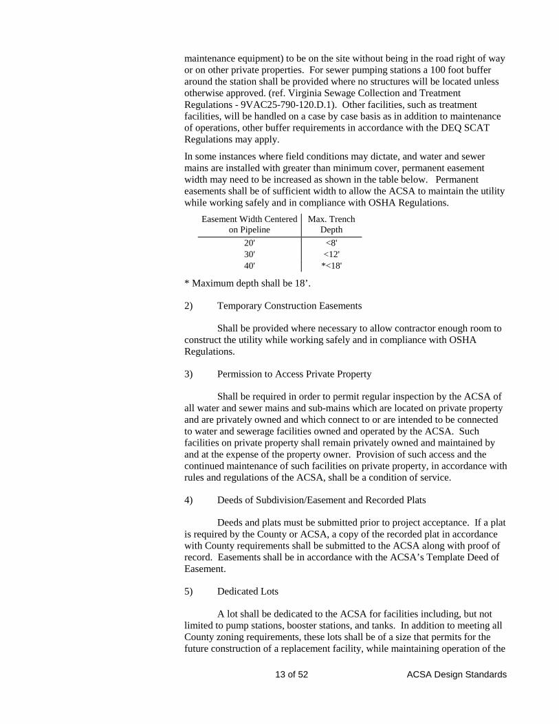
In some instances where field conditions may dictate, and water and sewer mains are installed with greater than minimum cover, permanent easement width may need to be increased as shown in the table below. Permanent easements shall be of sufficient width to allow the ACSA to maintain the utility while working safely and in compliance with OSHA Regulations.
Easement Width Centered on Pipeline
Max. Trench Depth
20' <8' 30' <12' 40' *<18'
* Maximum depth shall be 18’.
2) Temporary Construction Easements
Shall be provided where necessary to allow contractor enough room to construct the utility while working safely and in compliance with OSHA Regulations.
3) Permission to Access Private Property
Shall be required in order to permit regular inspection by the ACSA of all water and sewer mains and sub-mains which are located on private property and are privately owned and which connect to or are intended to be connected to water and sewerage facilities owned and operated by the ACSA. Such facilities on private property shall remain privately owned and maintained by and at the expense of the property owner. Provision of such access and the continued maintenance of such facilities on private property, in accordance with rules and regulations of the ACSA, shall be a condition of service.
4) Deeds of Subdivision/Easement and Recorded Plats
Deeds and plats must be submitted prior to project acceptance. If a plat is required by the County or ACSA, a copy of the recorded plat in accordance with County requirements shall be submitted to the ACSA along with proof of record. Easements shall be in accordance with the ACSA’s Template Deed of Easement.
5) Dedicated Lots
A lot shall be dedicated to the ACSA for facilities including, but not limited to pump stations, booster stations, and tanks. In addition to meeting all County zoning requirements, these lots shall be of a size that permits for the future construction of a replacement facility, while maintaining operation of the
14 of 52 ACSA Design Standards
existing facility. A deed and plat shall be recorded and provided to the ACSA showing the lot dedicated to the ACSA.
d. Separation of Utilities
1) Separation of water and sewer lines shall be in accordance with Section 02080 Utility Pipe and Materials of the Construction Specifications.
2) Separation of water and sewer lines from electric, fiber optic, gas lines and other privately owned public utilities shall be in accordance with utility company requirements and state law. A minimum separation distance from ACSA utilities shall be 5 feet horizontally and 2 feet vertically unless otherwise approved by ACSA Engineering Dept.
3) Water and sewer mains shall be a minimum of 20 feet from buildings. Horizontal separation of water and sewer lines from other structures such as storm sewer, sidewalks, and curbing shall be a minimum of 5 feet where possible to reduce future maintenance costs. Existing Services and Disruption of Service
Existing water and sewer services shall be maintained throughout construction. The designer shall anticipate any requirements for bypass pumping and/or temporary waterlines and show the requirements on the plans. This shall include a written sequence of events in order to properly plan the service disruption (location of valves to close, manholes to plug, bypass pump sizes, order of work to complete, etc.). Any valves needed in order to isolate a section of waterline shall be included on the plans and properly labeled. Any work requiring that services be disrupted to existing customers shall only be done in close coordination with ACSA Engineering Technician and shall be planned well in advance (based on the service area affected) in order to allow proper notice. Large planned disruptions may be required to be performed during off-peak times or during nights/weekends.
e. Plan Sheet Preparation & Drafting Standards
1) General
Plans shall be of sufficient detail and scale to accurately indicate all pertinent design and construction details for a comprehensive interpretation of the work to be performed. If plans are deemed to be illegible or incomplete by the ACSA, plans will be returned with a request to revise and resubmit plans satisfactory for review. a) Water and sewer lines - show the location of all water and
sewer line appurtenances and accessories and accurate plan and profile design drawings for the proposed lines;
b) Water and sewerage facilities such as water storage tanks or
pumping equipment, sewage pumping stations, or other like equipment - provide detailed plans and specifications on design, equipment, materials, and construction of such facilities.
15 of 52 ACSA Design Standards
2) Engineering and Plan Requirements for Safety:
All project designs shall incorporate safety components in accordance with the Occupational, Safety, and Health Administration (OSHA), the Virginia Department of Labor and Industry (DOLI), and/or the requirements of the ACSA policies for employee safety and the ACSA Approved Products List. This shall include but not be limited to personnel safety railings, ladders, fall protection and personnel anchor systems, personnel recovery devices, ventilation systems, arc-flash studies and electrical box labeling, electrical safety matting, personal protective equipment boxes with contents applicable to the facility hazards, eye wash units, safety showers, fire extinguishers/suppression systems, proper placards/labels/lighting applicable to the facility hazards, break panels with lock-out/tag-out capability, fencing, and emergency/security lighting. All equipment specified shall meet OSHA and ANSI standards applicable to the identified hazard. Every effort shall be made to engineer out safety hazards requiring special equipment or procedures for operation and maintenance.
3) Specific Plan Sheet Requirements
a) Plan sheets shall measure either 22 inch x 34 inch or 24 inch x
36 inch and be oriented in landscape view. b) All plan submittals must include a cover sheet. The front sheet
shall include the following. A second sheet may be added if all of the following items will not fit legibly onto the cover sheet. Please also refer to the Submittal Checklist which can be found at www.acsawater.com. • Project name • Vicinity Map (Provide adequate detail to permit ACSA
Staff to easily locate the site in the field – including existing and proposed roadways.)
• Index of sheets • Standard notes as applicable (may be included on sheet 2 if
necessary) • Legend (may be included on sheet 2 if necessary) • Original seal, signature, and date of the licensed
Professional Engineer or Class B Surveyor. Following sheets shall bear the copy of such seal.
• Names, addresses, and telephone numbers of the owner or developer and engineer.
• Table of estimated quantities (may be included on sheet 2 if necessary) − Line sizes and lengths − Number of manholes and total vertical depth − Number of hydrants − Number, type, and sizes of valves − Number of meter boxes and cleanouts
• Horizontal and vertical coordinate systems shall be clearly defined.
16 of 52 ACSA Design Standards
c) Standard Notes and Requirements: The following General Water and Sewer Conditions shall be shown on the cover sheet of each set of plans, as applicable:
(i) All work shall be subject to inspection by Augusta County ACSA inspectors. The contractor shall notify the ACSA Engineering Department at 540-245-5670 at least 48 hours prior to the start of any water and sewer utility work. Failure to comply or properly notify may result in additional work by the Contractor in order to permit the necessary inspection and /or disconnection from the system.
All mainline taps, valve operation, opening of hydrants, manhole coring, etc. shall be done by ACSA Personnel or with ACSA Inspectors present.
(ii) For Dedicated Facilities such as tanks, pump stations, booster stations, etc., ACSA will require the following (design/construction):
- That all safety devices, equipment, and any specialized personal protective equipment needed for the facility are included/provided with the project design and construction.
- Evaluation of all proposed devices, equipment, and specialized personal protective equipment against the Approved Products List and/or policy requirements.
- The requirements under Section 01110 – General Requirements pertaining to submittals shall apply to all safety equipment.
The contractor shall be required to provide facilities for safe access to the work by ACSA employees, as needed.
(iii) The contractor is ultimately responsible for all job site safety and assurance that all requirements of the Occupational Safety and Health Administration (OSHA), Department of Labor and Industry (DOLI), and the current Building Code are maintained. However, in the event that an ACSA Engineering Technician observes conditions that could endanger life/limb of any person on the job, the technician will immediately notify the job site superintended/foreman and the ACSA Engineering and Administration Offices. If a jobsite safety issue is confirmed by the superintendent/foreman/ACSA and the situation continues ACSA may contact OSHA.
On-site ACSA staff will require a preconstruction safety plan be submitted for review at least 48 hours
17 of 52 ACSA Design Standards
prior to any work involving ACSA owned facilities requiring confined space entry and/or working at heights in excess of 6 feet. The plan must be prepared by a competent person, as defined by OSHA/DOLI, and the employees performing the work must have proper training. Additionally, the contractor shall provide a plan prepared by an engineer or competent person (in accordance with OSHA requirements) for any trenching activities requiring engineered shoring, or where other hazards such as trenching with water accumulation or trenching where adjoining building/structures are endangered by the excavation.
(iv) All existing utilities adjacent to the proposed work may not be as shown on the plans and where shown, are only approximately located. The contractor shall contact Miss Utility at 800-522-7001 to have underground utilities marked in accordance with Virginia’s underground utility damage prevention act.
(v) All materials and construction shall comply with the most current version of the ACSA Design and Construction Standards.
(vi) All water and sewer pipes shall have a minimum of 42” of cover measured from the top of pipe unless otherwise approved. This includes all fire hydrant lines and service laterals.
(vii) A minimum vertical separation of 42” is required between water line and storm sewer culverts. When the 42” minimum separation cannot be achieved and where freezing is a possibility the water line shall be encased in concrete and insulated as approved by the ACSA. Concrete encasement and insulation shall extend a minimum of 60” beyond the centerline of the culvert in both directions or 60” beyond ends of culvert when parallel.
(viii) Contractor shall provide certification that proper compaction has been obtained for all backfill over and under water and sewer lines and appurtenances in accordance with the Construction Standards. This certification shall be signed by a professional geologist or engineer and state the exact area to which the certification applies. Testing shall be in accordance with the Design and Construction Standards.
(ix) Valves on dead-end lines shall be restrained in accordance with applicable standard details.
(x) Water lines shall not be placed within 30 horizontal feet of existing or proposed sanitary drain fields and
18 of 52 ACSA Design Standards
septic tanks. Water or sewer lines shall not be placed within 30 horizontal feet of existing or proposed underground storage tanks.
(xi) Joint restraint shall be provided for all bends, tees, dead end lines, and stubouts, in accordance with the applicable standard details.
(xii) When located in VDOT rights-of-way fire hydrants and all other appurtenances shall be located behind the ditch line.
(xiii) Contractor shall maintain water and sewer service to all existing customers throughout construction. This may require temporary lines, connections, and/or pumping.
d) One plan view may be shown for all proposed utilities as the scale and level of detail allows. A separate profile for each proposed utility shall be prepared with reference to other existing and proposed utilities and other features as necessary.
e) As a minimum the plan view shall show all items as listed on the Augusta County Submittal Checklist located at www.acsawater.com.
4) Minimum Size
a) The water line size shall not be less than eight inches (nominal size) in diameter for lines which will be extended and serve future connections, and where there are two or more fire hydrants, and no supporting grid system provided by either the existing or proposed layout.
b) The minimum size of the pipe where only one hydrant is to be provided or required shall be six inches in diameter provided the level of service requirements are met.
c) The ACSA reserves the right to specify the size of water mains on any project. If the ACSA specifies a water main larger than shown necessary by approved design calculations, the ACSA may participate financially in the project in accordance with ACSA OPPM Policy No. 10.2 System Improvements. In any case, the designer shall be responsible for properly designing the water system for domestic service and fire protection under all conditions.
d) Ten inch waterlines shall not be used.
19 of 52 ACSA Design Standards
e) Any departure in sizing shall be justified by hydraulic analysis and future water use and shall be considered only in special circumstances.
f) The horizontal scale for the plan and profiles shall be the same with a minimum scale of 1 inch equals 100 feet. The vertical scale shall be no smaller than 1 inch equals 10 feet.
g) Water Booster and Sewer Pump Stations
(i) Drawings for water booster and sewer pump stations shall be prepared and submitted in accordance with ACSA specifications.
(ii) Drawings and specifications shall be of such quality and contain sufficient details so that no misunderstanding may reasonably arise as to the extent of the work to be performed, the materials to be used, the equipment to be installed or the quality of the workmanship.
(iii) Drawings for water booster and sewer pump stations shall include a site plan drawn to a scale of not less than 1" equals 20' and shall contain existing and proposed contours on a two-foot contour interval. The boundaries of the site shall be clearly shown on the site plan and shall be permanently monumented in the field prior to completion of construction.
(iv) Detail drawings for water booster and sewer pump stations shall be drawn on a scale of not less than 1/4" equals 1'0". Drawings required to clarify construction details shall be drawn on an appropriately larger scale.
f. Record Plans
Record drawings shall be in accordance with Section 01110 - General Requirements of the Construction Specifications.
g. Casing Pipe
Steel casing pipe shall be provided for all road crossings, both bored and open cut, and for all railroad crossings. Casings shall be provided for all new road construction with mainline water and sewer crossings at the discretion of the ACSA. If a casing is not used for a sanitary sewer crossing, the sewer pipe shall be PVC C900 pipe, thickness Class DR-18 from manhole to manhole across the roadway. Steel casing may also be required for other special conditions as required by the ACSA. Steel casing for road crossings shall be in accordance with applicable standard details. Steel casing for railroad crossings shall be in accordance with the railroad permit for the applicable railroad company. Casing pipe shall be sized in accordance with the Construction Specifications Section 02080 – Utility Pipe and Materials 2.1.8.
20 of 52 ACSA Design Standards
2. Water
Water design shall be in accordance with the VDH Waterworks Regulations and these Design and Construction Standards.
Water mains and submains that will remain private, but will be connected to ACSA facilities, shall be designed, constructed, tested, and inspected in accordance with VDH Waterworks Regulations and these Design and Construction Standards.
a. Capacity
All main distribution pipelines shall be of a size to adequately serve all the needs of the proposed water system, in accordance with Section B.1.a. and b., including domestic and fire flow requirements.
1) Design Calculations
a) Design calculations shall be in accordance with VDH Waterworks Regulations Section 12VAC5-590-690, Capacity of Waterworks. A minimum working pressure of 20 psi at the service connection based on the greater of maximum hour or maximum day plus applicable fire flows must be evaluated.
b) Water line design will be based on the Hazen-Williams formula. A C-factor of 120 shall be used for new pipe and a C-factor of 100 shall be used for older pipe (steel, cast iron).
c) A hydraulic model in accordance with Section 2.b (Design Flow and Model Development) of the Design Standard shall be submitted for all newly proposed water extensions, which demonstrates the adequacy of the proposed system. The model shall also demonstrate that the proposed system does not reduce available flows and pressure to the existing system. All requirements of Augusta County Ordinance 24 – Fire Flow shall be met in the hydraulic model.
d) Maximum velocity allowed in design is 8 ft/s for cement lined ductile iron pipe.
e) At the time of design calculation submittal, a hydrant flow test form(s) shall be submitted. Hydrant flow tests are available by contacting the ACSA in accordance with Section 2.b.1 Fire Flow, of these Standards. A valid test shall drop the pressure at the critical location in the system at least 25% unless waived by ACSA Engineering Department.
b. Design Flow and Model Development
Design flow shall be the greater of the required fire flow plus peak domestic demand or the target for the level of service standards. Design flow shall consider future demand, including all potential developable land within the area of extension. Below, these items are described in greater detail.
21 of 52 ACSA Design Standards
The ACSA may require a higher design flow if indicated by site conditions.
Following a flow test(s) at the proposed connection point in the field, unless waived by ACSA engineering staff all, all system extensions must be modeled to demonstrate that the proposed system extension representing the entire development can meet the performance standards of the ACSA and the Augusta County Ordinance requirements for flow and duration (2hrs) in accordance with Section 2.b. of these Standards. To achieve this, during the field flow test multiple flow and pressure data points should be recorded from 0 flow to maximum flow to provide sufficient information for setting up a performance curve in a computer model. A minimum of 2 scenarios should be submitted – 1) At the conditions observed during the flow test and 2) At system conditions following a 2 hour fire flow (lowering the tank(s) from the normal low). Where the elevation of a proposed development is within 50 ft of the base of an existing water storage tank(s), a 3rd scenario will be required to ensure that that proposed development will not impact the “effective storage” of the existing tank(s). The modeler should provide other scenarios as needed to address phases of the project that may impact fire flow in the extended system. In some instances, a construction phase may be required to include the construction of additional water infrastructure to ensure that the fire flow requirements can be met for the proposed phase of the development.
Modeling the 2 hour fire flow condition should be done by adjusting
the measured pressure down to match the tank elevation(s) from a normal low (from ACSA) to an elevation that accounts for 2 hours of volume being taken from the tank(s). The maximum amount of flow available from the modeled supply must correspond with the test data and limits available flow to the point at which the critical hydrant/system location reaches 20 psi. Utilization of a tank with control valve or a pump in the computer model to mirror the system conditions observed during field testing is expected. Domestic demands should be distributed in accordance with good modeling practices to adequately spread the demands across the junctions/nodes. Fire flows should be checked at various locations that may be at higher elevations or hydraulically remote or both while ensuring that no node in the extended system drops below 20 psi. Limiting the number of dead ends and maximizing the number of loops in the system extensions will be expected in accordance with the Virginia Department of Health Waterworks Regulations 12VAC5-590-1130 – System Design.
A node and/or hydrant report, pipe report, pump/valve report, a map
matching master plan layout labeled with street names, pipes, and junctions, as well as a conclusion of the results shall be included with the submittal for review.
If a sprinkler system will be utilized, the gallons per minute and the
pressure required for the demand of the sprinkler system shall be submitted for review. If a pump is required for the system, that information shall also be submitted to ACSA for review.
Note: Multiple tanks, sources, and in some instances the pipe network
configuration can increase the complexity of the analysis making small, partial system models for extensions more complicated and impractical for obtaining the needed results. In these instances and in areas where flows are at or near
22 of 52 ACSA Design Standards
limits required by these Standards or the Augusta County Ordinances, a more detailed system analysis in coordination and partnership with the Service ACSA should be expected.
1) Fire Flow
Chapter 24 of the Augusta County Code sets the fire flow requirements. The County will determine all nonresidential, and when necessary, residential fire flow requirements based on ISO guidelines. The Augusta County Fire Protection Design Policy is at www.acsawater.com for reference titled Augusta County Fire Protection Design Policy. Prior to submittal of design calculations, the design engineer should acquire required hydrant flow test data for design calculations in accordance with the ACSA OPPM Policy No. 10.5 Water System Flow Testing. See www.acsawater.com for the Hydrant Flow Test Form.
2) Level of Service Standards
For residential areas where the required fire flow is less than 1000 gpm, a minimum target design flow of 1000 gpm shall be used. Design flows less than 1000 gpm may be approved for local service when a level of fire protection in accordance with the County Ordinance can be obtained, and there is no possibility for a future extension of the waterline.
For schools, multi-family residential, commercial, and industrial areas, a minimum target of 2000 gpm shall be used for design purposes. If the County specifies a required fire flow greater than 2000 gpm, the water system shall be designed to provide this flow, or other on-site or off-site improvements shall be made as approved/required by the ACSA and County Fire Chief to provide the necessary level of service.
3) Domestic Demand
Domestic demand shall be estimated using the guidelines in the VDH Waterworks Regulations.
Average daily demand shall be calculated using the daily water consumption rates found in the VDH Waterworks Regulations. The ACSA currently uses an average of 2.8 persons per residence.
When a commercial or industrial development is proposed, but the specific industries are unknown, the designer shall use an average daily flow of 1500 gpd per acre for light industrial/commercial and 2000 gpd per acre for heavy industrial/commercial.
Peak domestic demand shall be calculated using twice average daily demand.
23 of 52 ACSA Design Standards
4) Future Demand
The designer shall estimate, based on the County's Comprehensive Plan and the ACSA’s Master Plan, the projected demands for developable land in the project area, if the proposed waterline could be extended to serve those areas. Based in the results of this estimate, the ACSA may participate in the project in accordance with the ACSA OPPM Policy No. 10.2 System Improvements.
c. Pressure
All extensions of existing water systems or new water systems shall provide a minimum 20 psi residual pressure on the new line(s) and at the critical locations in the system under design flow conditions. Upon identification of the proposed development, the ACSA will determine the locations(s) to be monitored during flow tests.
Design flow shall be calculated according to Section 2.b. of these Standards.
The ACSA may require a higher residual pressure if required by system conditions.
The test pressure for waterlines shall be specified on the plans. Test pressure shall be 1.5 times the working pressure at point of test, but not less than 1.25 times the working pressure at the highest elevation along the test section.
d. Effective Storage
Effective storage is the volume of water in the storage tank above the level that provides 20 psi to all connections under design flow conditions. This volume may include domestic, emergency (ex. power outage), and fire flow storage.
Any proposed development or extension to the water system shall be designed so that the storage tank is 100% effective for that development or extension. The development or extension shall also not decrease the effective storage to the rest of the water system. Modeling a “tank empty” scenario will be required where the elevation of the proposed system extension may impact the effective storage of the system.
e. Pipe
Water main material shall be in accordance with Sections 02510 - Water Distribution and 02080 - Utility Pipe and Materials of the Construction Specifications.
All water pipes shall have a minimum cover of 42 inches unless otherwise approved.
24 of 52 ACSA Design Standards
1) Minimum Size
a) The water line size shall not be less than eight inches (nominal size) in diameter for lines which will be extended and serve future connections, and where there are two or more fire hydrants, and no supporting grid system provided by either the existing or proposed layout.
b) The minimum size of the pipe where only one hydrant is to be provided or required shall be six inches in diameter provided the level of service requirements are met.
c) The ACSA reserves the right to specify the size of water mains on any project. If the ACSA specifies a water main larger than shown necessary by approved design calculations, the ACSA may participate financially in the project in accordance with ACSA OPPM Policy No. 10.2 System Improvements. In any case, the designer shall be responsible for properly designing the water system for domestic service and fire protection under all conditions.
d) Ten inch waterlines shall not be used.
e) Any departure in sizing shall be justified by hydraulic analysis and future water use and shall be considered only in special circumstances.
2) Surface Water Crossings
The water line shall be a minimum of 42 inches below the stream bed surface. Where water lines are intended to cross streams, rivers or other surface waters (either continuous or intermittent flows), only underwater crossings will be permitted in accordance with the Standard Details. The water line shall be of special construction having flexible watertight joints depending on installation depth. Valves shall be provided at both ends of the water crossing so that the section can be isolated for tests or repair; the valves shall be easily accessible and not subject to flooding. A water meter and valve shall be installed at one end of a major crossing and not subject to flooding for the purpose of locating leaks.
f. Appurtenances
1) Dead Ends
In accordance with Virginia Department of Health Water Works Regulations 12V4C5-590-1130 – System Design, dead end lines shall be minimized by looping of all water lines where practical. Where dead end lines occur, a fire hydrant or blow-off hydrant for flushing purposes shall be provided (See Standard Details). Fire hydrants are preferred where practical and where waterline is a minimum of 6 inches. The ACSA reserves the right to require water lines to be looped.
25 of 52 ACSA Design Standards
2) Valves
a) Gate Valves
Approved gate valves shall be installed at all pipe junctions and street intersections in such a manner as to control and cut off flows in all segments of the system. All tees shall be isolated with three valves; crosses by four. At intersections valves shall be located together and on the same side of the roadway outside the pavement, unless otherwise approved by ACSA Engineering Department and VDOT.
In other areas, gate valves will be required every 800 feet at a minimum, except as may otherwise be approved by the ACSA. Valves shall be located upstream and adjacent to all existing and proposed fire hydrants.
Locations of valves shall consider potential service interruption to customers as may be required for future maintenance.
b) Air Release Valves
Approved automatic air release valves shall be installed at high points in the water main. Valve shall be provided with a 1 inch tap and the orifice shall be sized according to the manufacturer’s literature. Air release valves shall also be in accordance with the Standard Details.
c) Blow-Off Valves
Blow-off hydrants shall be provided at any dead end in a water main and low points. Blow off hydrants shall also be in accordance with Standard Details.
Automatic blow off assemblies shall be provided as required for water quality specified by the ACSA.
No flushing device shall be directly connected to any sewer. Chambers or pits containing blow-offs shall be drained to atmosphere where they will not be subject to flooding, or to an absorption pit located above the seasonal groundwater table.
3) Hydrants
Fire hydrant location shall be in accordance with Augusta County Fire Protection Design Policy as found at www.acsawater.com.
In addition to the Augusta County Fire Policy, the following requirements shall apply. No hydrant shall be more than 800 feet from any other hydrant measured along the centerline of the street or other
26 of 52 ACSA Design Standards
public right-of-way. Fire hydrants shall be placed no closer than 40 feet from any existing or proposed structures.
Fire hydrants shall be connected only to water systems adequately designed for fire flows and domestic flow, unless otherwise approved by the ACSA. In addition fire hydrants shall not be connected to any waterline smaller than 6 inches.
All cul-de-sacs with public water shall include a fire hydrant in lieu of a blow-off assembly where practical and where the line size is a minimum of 6 inches. Hydrants in lieu of blow-down assemblies shall also be located at low places in proposed waterlines where practical.
For non-residential on-site fire hydrants and the fire service line is solely intended for fire protection and no domestic usage will be provided from line, a double check-detector assembly backflow preventer (privately owned and maintained) shall be provided in a vault at the property line. Fire hydrants placed on private property in such a manner will be private hydrants. Maintenance and proper operation of these hydrants shall be the sole responsibility of the property owner.
Fire hydrants shall be provided with bollards for protection where not located behind curb or other form of physical barrier.
Reference Appendix 2 for the Augusta County Fire Protection Design Policy.
4) Service Laterals
a) Taps, laterals and meter boxes are to be installed for all lots or parcels of land within developments and commercial/industrial lots and shall extend from the main to the property line of the lot or parcel by the Contractor, unless otherwise authorized by ACSA. (A hook-up fee discount may be applied as detailed in the ACSA Rate Schedule). For services requiring a 2 inch meter or smaller, the lateral shall be stubbed out at the property line with a female adapter and plug in accordance with the Standard Details. Services shall be shown for commercial/industrial lots at the site plan stage; for residential lots at the construction plan stage.
b) For single residential services located on the same side of the street as the main, laterals may be ¾ inch diameter. For double residential services and services located on the opposite side of the street as the main, the lateral shall be 1 inch diameter.
c) If laterals are to cross under the roadway, they shall be installed within 2 inch rigid, Schedule 40 PVC pipe as a casing in accordance with the Standard Details.
27 of 52 ACSA Design Standards
d) Lateral material type shall conform to the ACSA Approved Products List and the Standard Details.
5) Water Meters
Individual water meters are required for all single family homes, town homes, and other buildings and structures.
a) Temporary and permanent meters shall be supplied and installed in accordance with Section 02080 - Utility Pipe and Materials.
b) All water meters will be sized by the ACSA based on the fixture unit count of the facility. The peak demand of the facility shall be calculated using the ACSA's water meter sizing form, a copy of which is found at www.acsawater.com. This form is to be completed by the owner of the facility or his representative and submitted to the ACSA when submitting site plans for review. All standard residential connections are equipped with 5/8” meters.
c) For fire service lines, a separate connection and meter, in addition to the domestic meter for the property, is required. The meter shall be specified by ACSA and sized in cooperation with the fire sprinkler designer and ACSA. Hook-up Fees and installation requirements shall also be in accordance with the ACSA Rate Schedule. Backflow prevention shall be provided by the Developer in accordance with Section 2. d. 6) -Backflow Prevention, Policy 18.7 - Cross-Connection Control and Standard Details.
6) Backflow Preventers
All backflow prevention measure shall be in accordance with ACSA OPPM Policy 18.7 Rules and Regulations - Cross Connection Control and Backflow Prevention.
For interior sprinklers used for fire protection, backflow prevention shall be installed inside the building in accordance with BOCA requirements.
For on-site fire hydrants used solely for fire protection and not domestic flow. See Section 2.f.3 of these Design Standards.
g. Booster Stations & Hydro-pneumatic Tanks
Prior to submitting a booster station or hydro-pneumatic tank design, a Preliminary Engineering Report (PER) shall be submitted and approved by the agencies having jurisdiction. These agencies shall include, but not be limited to the VDH and the ACSA. The PER shall address such items as the proposed
28 of 52 ACSA Design Standards
service area, the overall effect on the existing water system, an analysis of future demands for water, cost and availability of providing service utilizing the ACSA's existing pressure zones, and a cost benefit analysis of any feasible alternative to providing public water.
1) General Requirements
Water booster stations may be provided for the conveyance of potable water. Water booster stations will not be allowed for providing fire flow. System design shall include but not be limited to the technical provisions of these Standards and those of the VDH Waterworks Regulations.
Provisions shall be made to accommodate future needs if the initial flow is significantly less than the ultimate demand. The sizing and configuration of the pumping station shall be within the parameters set forth in the approved PER. The proposed facilities shall be based on ultimate flows unless an interim flow design shall have been incorporated in the approved PER.
Construction must meet all BOCA Code standards and be inspected by the Augusta County Building Inspections Department as well as the ACSA.
2) Capacity
Capacity design for the booster station shall take into consideration such parameters as minimum, average, and peak demands. Initial and ultimate demands shall be taken into account.
3) Hydraulic Analysis
Pump selection shall be based on a hydraulic analysis of the system. This shall include domestic flows and fire flows and available supply to the booster station.
Calculations shall be prepared and system head capacity curves developed that will show static head, and total dynamic head for both single and multiple pump operation. The curve shall also show the pump performance curve for both single and multiple pump operation. Where variable speed pumping is contemplated, pump performance curves shall show performance at maximum speed, minimum speed just above static head and several intermediate speeds that will clearly indicate pump operation.
Particular attention shall be given to the available versus required net positive suction head (NPSH) of the proposed system. Booster pump shall not create negative pressure in the suction line and shall not reduce the available flow below established standards or further degrade the available flow. Improvements to the existing system shall be provided as necessary to maintain required pressure and flow.
29 of 52 ACSA Design Standards
4) Pump Selection & Equipment
The type of equipment to be installed in the pumping station will be influenced by the interim and ultimate capacity of the station and an evaluation of the period of time that the service of the station will be required.
Equipment selected for use in the booster station shall be in accordance with the Approved Products List coordinated with the ACSA in order to provide a system that is consistent with other satisfactory systems in operation.
At least two pumping units shall be provided in accordance with the Approved Products List. If only two units are provided, each shall be capable of delivering the peak demand. If more than two units are installed, they shall have sufficient capacity so that if any one pump is out of service, the remaining pumps are capable of carrying the peak demand. Pump selection shall consider operating speeds, motor efficiency, and cycle times. The pumping units shall:
a) Have ample capacity to supply the peak demand without overloading.
b) Be driven by a prime mover able to operate against the maximum head and air temperature which may be encountered.
c) Be designed so that at full capacity, each pump will run no greater than 16 hours per day.
d) Be designed to run for a minimum of one minute each time they start and shall not exceed three starts per hour, per pump, unless permissible by pump manufacturer and approved by ACSA.
Additional information regarding pump selection and equipment can be found in Section 11315 – Water and Wastewater Pump Station, Section 16010 – Electrical Requirements for Pump Stations, and the Approved Products List.
5) Power Requirements
Consideration must be given to designs which produce minimum power requirements to accomplish the functions required. On all motors 5 HP or greater, three phase power shall be considered to provide the necessary starting torque and to provide the most efficient and cost effective design. If three phase power is not available, a variable frequency drive shall be provided as approved by the ACSA to provide three phase power to the pumps. An energy analysis shall be provided which demonstrates that the design is the most efficient and cost effective system for the ACSA to operate.
30 of 52 ACSA Design Standards
Transient voltage surge protection must be provided on all incoming power sources. A phase monitor to protect against phase imbalances. Three-phase service shall be provided, shall be either closed delta or four-wire wye, in order to reduce the risk of phase imbalances.
Back-up generators approved by the ACSA must be provided by the developer with all water booster stations.
6) Gauges and Meters
Pressure gauges shall be installed on both the suction and discharge lines of booster pumps. A flowmeter in accordance with the Approved Products List shall be provided by the Developer to provide totalized flow on a remote digital display as well as components provided for SCADA monitoring. All booster pumps shall have run time meters.
7) Controls & SCADA
Booster pumps shall be located and controlled so that:
a) The intake pressure shall be at least 20 psi (unless conditions could dictate different minimum pressures) when the pump is on normal operation.
b) An automatic pressure cutoff or a pressure regulating valve shall be provided to prevent suction line pressure from dropping below 10 psi.
c) The pumps shall not start more than three times per hour unless permissible by pump manufacturer and approved by ACSA. Calculations shall be prepared which demonstrate this.
d) The following items shall be monitored and transmitted via the SCADA system as applicable.
(i) power failure to each pump
(ii) discharge pressure
- suction pressure
- phase failure
- pump failure – each pump
- run time – each pump
- pumping rate (gpm)
- total gallons pumped
31 of 52 ACSA Design Standards
- building temperature
- clear well level
- control valve position status
- storage tank levels
- generator status on/off, start failure
e) Components of the SCADA system shall be as shown in the Approved Product List. Panels shall be assembled by an electrical contractor or system integrator experienced and qualified to perform such work.
8) Electrical
The designer shall determine the availability of electric service and coordinate the available electrical service with that required for the facility. The designer shall also determine the need for primary service extension. All costs for extension of electric service shall be the responsibility of the Developer and made part of the overall construction cost. Costs for extension of electric service shall not be rolled into a minimum consumption billing for startup of the facility.
All motors, motor control and other electrical equipment shall be housed in a weatherproof, above-ground structure in accordance with Part 13 of this Section. Adequate provisions shall be incorporated for the proper heating, ventilation, drainage and flood protection in order to insure maximum security, reliability, electrical and personnel safety.
Conduits of non-ferrous material buried underground shall have a detectable tracer buried in the trench approximately 6 inches above the conduit.
9) Lighting
Booster stations housed in buildings shall be adequately lighted in accordance with VOSH and other applicable codes and standards. Interior and exterior booster station lighting shall be in accordance with Section 16500 – Lighting.
10) Ventilation
Adequate ventilation shall be provided for all booster stations. Forced draft ventilation of at least six changes of air per hour (continuous operation) shall be provided.
32 of 52 ACSA Design Standards
11) Heating
Provision shall be made for adequate heating for comfort of the operator and the safe and efficient operation of the equipment. Heaters shall be electric hydronic baseboard type or as otherwise approved by the ACSA. In booster stations not occupied by personnel, only enough heat needs be provided to prevent freezing of equipment.
12) Moisture Control
Dehumidification equipment shall be provided for all booster stations.
13) Building Design
The architecture of the booster station shall be compatible with the surrounding neighborhood. The booster station shall be of block or concrete construction, in accordance with Section 03310 – Insulated Concrete Forms or Section 04100 – Generic Block Building Construction (CMU). All booster stations shall be of sufficient size and contain adequate clearances to provide ample room for maintenance. A minimum workspace of three feet shall be provided around all piping and equipment.
14) Site Grading
Site grading, seeding or sodding, trees or shrubs shall be provided to present a finished appearance, as approved by the ACSA, consistent with the zoning, site construction for pump stations, general appearance of the surrounding area, and Section 02200 – Site Construction for Pump Stations.
15) Fencing
Approved fencing with gates shall be provided to properly protect the facility, in accordance with Section 02821 – Chain Link Fences and Gates.
16) Access
An all-weather road, with storm drainage, parking shall be provided for easy access to the booster station, in accordance with Section 02200 – Site Construction for Pump Stations.
17) Vandalism
Booster station should be designed so as to minimize the risk of vandalism.
33 of 52 ACSA Design Standards
h. Cross-Connection Control
All applicants for water services to serve nonresidential buildings must meet the ACSA Cross-Connection Control Program requirements. Both residential and non-residential buildings which have sprinkler and/or irrigation systems must also meet the ACSA Cross-Connection Control Program requirements for these types of systems. Construction plans shall indicate the location and type of backflow prevention for the project. A gate valve shall be provided at the right-of-way or easement boundary to separate the public system from the private.
The Augusta County Cross-Connection Control Program is included in ACSA OPPM Policy 18.7 Rules and Regulations and Backflow Prevention.
34 of 52 ACSA Design Standards
3. Sewer
Sewer design shall be in accordance with the DEQ SCAT Regulations and these Design and Construction Standards.
a. Gravity Sewers
1) General
Private extensions shall be constructed in accordance with the applicable building codes using cleanouts in lieu of manholes when line sizes and other factors permit. This assists the ACSA in removing potential sources of Inflow and Infiltration and should provide a more cost effective and less maintenance intensive system for the owner.
Sewers shall not be located in areas subject to flooding or in drainage ditches or basins that encourage inflow and infiltration unless otherwise approved by the ACSA. Sewers shall be located outside of jurisdictional wetland areas whenever possible.
General Structural Design - The structural design of sewers shall conform to the methods given in the ASCE Manuals of Practice 60 for the Gravity Sanitary and Sewer Design and Construction.
2) Capacity
a) Population Served
Generally, the capacities of lateral, trunk, and interceptor sewer systems should be designed for the estimated ultimate build out population of the service area being considered for development. Any known future development shall be considered as well.
The designer shall also estimate the ultimate build out population for the total sewer shed area. Future population densities should consider the Augusta County Comprehensive Plan, ACSA Master Plan, Zoning Ordinance, and Subdivision Ordinance as applicable. Based on the results of this estimate, the ACSA may participate in the project in accordance with ACSA OPPM Policy 10.2 System Improvements.
b) Average Daily Flow
New sewer systems shall be designed on the basis of an average daily per capita flow of sewage in accordance with the DEQ SCAT Regulations.
For residential developments, this flow is 100 gallons per person per day. These figures are assumed to cover infiltration. The ACSA currently uses an average of 2.5 persons per residence.
Equivalent flows from motels, schools, hospitals, etc. shall be based upon that of the DEQ SCAT Regulations.
35 of 52 ACSA Design Standards
When a commercial or industrial development is proposed, but the specific industries are unknown, the designer shall use an average daily flow of 2000 gpd per acre.
When deviations from the foregoing per capita or per acre rates are proposed, the designer shall supply sufficient information, substantiated by sound engineering judgment to verify the design, with the submission. This information shall be subject to approval by the ACSA.
c) Peak Flow
(i) Laterals & Sub-Mains
Minimum Peak Design Flow shall be 400 percent of the average daily flow.
(ii) Main Trunk and Interceptor Sewers
Minimum Peak Design Flow shall be 250 percent of the average daily flow.
3) Alignment & Slope
a) General
Sewers shall have a uniform slope and straight alignment between manholes. Gravity sewer size shall normally remain constant between manholes.
b) Minimum Slope & Velocity
Minimum grades shall not be less than those required to produce a velocity of no less than two feet per second when the size pipe selected is flowing full using a material roughness coefficient, "n" value, of 0.014, in the Manning Formula.
Pipe sizes shall be based on design flow and not increased in size in order to take advantage of a decreased grade, except with ACSA approval.
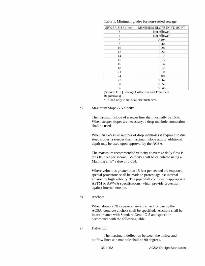
Minimum grades shall be in accordance with the following table.
36 of 52 ACSA Design Standards
Table 1. Minimum grades for non-settled sewage
SEWER SIZE (Inch) MINIMUM SLOPE IN FT/100 FT 3 Not Allowed 4 Not Allowed 6 0.49* 8 0.40
10 0.28 12 0.22 14 0.17 15 0.15 16 0.14 18 0.12 21 0.10 24 0.08 27 0.067 30 0.058 36 0.046
(Source: DEQ Sewage Collection and Treatment Regulations) * - Used only in unusual circumstances.
c) Maximum Slope & Velocity
The maximum slope of a sewer line shall normally be 15%. When steeper slopes are necessary, a drop manhole connection shall be used.
When an excessive number of drop manholes is required to due steep slopes, a steeper than maximum slope and/or additional depth may be used upon approval by the ACSA.
The maximum recommended velocity at average daily flow is ten (10) feet per second. Velocity shall be calculated using a Manning’s “n” value of 0.014.
Where velocities greater than 15 feet per second are expected, special provisions shall be made to protect against internal erosion by high velocity. The pipe shall conform to appropriate ASTM or AWWA specifications, which provide protection against internal erosion.
d) Anchors
When slopes 20% or greater are approved for use by the ACSA, concrete anchors shall be specified. Anchors shall be in accordance with Standard Detail G-5 and spaced in accordance with the following table.
e) Deflection
The maximum deflection between the inflow and outflow lines at a manhole shall be 90 degrees.
37 of 52 ACSA Design Standards
4) Depth
In general, sewers should be sufficiently deep as to receive sewage from basements. Elevations shall be shown on the plans for service lateral inverts as well as the finished floor of the lowest floor proposed to be served.
All sewers shall be constructed in such a manner that a minimum of 3.5 feet of cover is maintained between the top of the pipe and the finished grade or ground elevation. Greater depths may be required if deemed necessary to provide service to adjacent properties or to serve lower lying properties. Where approved by the ACSA and conditions dictate that the cover be less than 3.5 feet, ductile iron pipe, thickness class 50 shall be required. Sewers installed with 15 feet of cover or greater shall be constructed of C900 PVC pipe, thickness Class DR-18. Maximum depth shall be 18 feet unless otherwise approved by the ACSA.
5) Size
No public sewer shall be less than 8 inches in diameter. The ACSA reserves the right to specify the size of sewer mains on any project. If the ACSA specifies a sewer main larger than shown necessary by approved design calculations, the ACSA may participate financially in the project according to ACSA OPPM Policy No. 10.2 System Improvements. In any case, the designer shall be responsible to properly design the sewer system for the estimated population to be served.
6) Sewer Connections
a) Connections to sewer lines 18 inches in diameter or larger shall only be made at manholes.
b) When connections are made to existing manholes, invert shaping shall be modified by the Contractor to accommodate the new connection.
c) For residential connections, a minimum 6 inch sewer lateral may be provided for a maximum of two residential connections and minimum 4 inch for individual connections in accordance with Standard Detail S-2.
For commercial subdivisions, sewer service laterals shall be provided by the ACSA at the time of payment of connection fees (typically at the time of site plan approval for each additional lot.
Site plans submitted for lots located in commercial subdivisions shall indicate proper closure of existing unused sewer laterals as part of the site plan. This includes removal of
38 of 52 ACSA Design Standards
all cleanouts and permanently capping the line on the same side of the road as the main.
d) Sewer laterals shall be constructed to the property line and a cleanout provided immediately at its terminus, installed to a point flush with the finish grade, or when the finish grade is unknown, to a point sufficiently above the existing grade. All openings shall be plugged and sealed with a watertight plug until line is put in to use. See Standard Detail S-2.
e) Direct connections to the public sewer of roof drains, sump pumps, holes in floor drains, foundation drains, leaking laterals and other direct sources on inflow or infiltration into the public sewer system are prohibited.
f) At all junctions where a smaller diameter sewer discharges into a larger one and at all locations where the sewer increases in size, the invert of the larger sewer shall be lowered so that the energy gradient at design flow of the sewer at the junction is at the same level. Two approximate methods for securing this result which may be used are as follows:
(i) Align the 80% capacity flow level of both sewers at the same elevation, or
(ii) Position the crown of both sewers at the same elevation.
g) Sewer joints shall be in accordance with ASTM design standards and/or according to manufacturer's recommendations. Sewer joints shall be designed to prevent infiltration and to prevent the entrance of roots.
7) River or Stream Crossings and Pipe Installation in Marshy Areas
Each river or stream crossing shall be submitted for review to the Virginia Marine Resource Commission (VMRC) using the Joint Permit Application (JPA) process and proof of approval by VMRC shall be provided to ACSA.
River and stream crossings shall be constructed of ductile iron pipe, thickness class 50, manhole to manhole, and encased in concrete in accordance with Standard Detail G-6 and as required by the JPA process. The ACSA reserves the right to require ductile iron river-crossing pipe and concrete encasement for pipe installation crossing rivers, streams, ditches, shallow areas or marshy areas. The pipe and joints shall be tested in place and shall exhibit zero infiltration. The pipe joints shall be designed and constructed for impacts due to hydraulic longitudinal and vertical loads and protected from erosion.
Minimum cover over the concrete encasement shall be 3 feet, in accordance with Standard Detail G-6.
39 of 52 ACSA Design Standards
Sewers shall remain fully operational during 25-year flood/wave action.
Sewers shall be allowed to lie on piers across ravines or streams when it can be demonstrated that no other practical alternative exists. Such sewers on piers shall be constructed in accordance with the requirements for sewers entering or crossing under streams. In addition, a stream flow analysis using HEC methods to determine the effect of the piers shall be performed by the designer as required by the ACSA or other agencies having jurisdiction.
Construction methods and materials or construction shall be such that sewers will remain watertight and free from change in alignment or grade.
b. Manholes
1) General
Standard and drop manholes, service connections and other appurtenances shall be designed and constructed in accordance with the Standards.
2) Layout
Manholes shall be installed at the end of each line, at all grade, size, or alignment changes, and at all sewer line intersections. Terminal cleanouts may be permissible in sidewalk collectors or as approved by ACSA.
In addition, manholes shall be provided at intervals not exceeding 400 feet on all sewers 15 inches in diameter or less and not more than 500 feet apart on sewers 16 inches in diameter or larger.
3) Size
Size of sewer manholes shall be in accordance with Standard Details. Manholes larger than minimum size may be required where pipe deflection or intersection of two or more upstream lines occur.
Monolithic bottoms with extended base may be required in unstable soil conditions or where floatation may be a problem. In areas subject to flooding or unstable soil conditions, calculations shall be performed which demonstrate that the standard manhole will not float, or that an extended base has been provided to prevent the manholes from floating. If extended bases are shown to be necessary, they shall be detailed on the plans.
4) Frame and Cover
In areas subject to flooding, and as required by the ACSA, manhole tops shall be raised above the flood elevation, or watertight manholes shall be provided in accordance with Standard Details.
40 of 52 ACSA Design Standards
Where the length of sewer line containing watertight manholes exceeds 1000 feet, a non-watertight or vented watertight manhole shall be provided every 1000 feet. Vented manholes shall be in accordance with Standard Detail S-8.
5) Inverts and Slope
Invert shaping shall be provided for all manholes in accordance with Standard Details S-5 and S-6. The slope through the manhole shall be the same as the slope of the main line incoming pipe or shall be a minimum of 2.5%. This incoming or minimum slope shall determine the drop across the manhole. Inverts in and out of the manhole shall be shown on the plans. The minimum slope of 2.5% across a 4 foot manhole is a drop of 0.10 feet. The maximum slope across a manhole shall be 15 percent which, across a 4 foot manhole, is a drop of 0.60 feet. The maximum slope of a gravity sewer line is also 15 percent.
Slopes of gravity sewers shall be in accordance with the Standards.
6) Force Main Receiving Manholes
Interior of force main receiving manhole and two downstream manholes shall receive an epoxy coating. Coating shall be 100 percent solids based epoxy binder combined with fibrous and flake fillers to minimize water vapor transmission and increase flexural strength. Material shall be specifically designed for manhole rehabilitation. Coating shall be corrosion resistant. Material shall be applied at 40-60 mils thick on vertical and overhead surfaces.
The invert shall be modified as necessary in the receiving manhole to ensure a smooth flow transition to the gravity flow section. Special consideration should be paid to design of the termination in order to prevent turbulence at this point.
7) Drop Manholes
When approved by the ACSA, drop manholes in accordance with Standard Detail S-5 shall be provided to break steep slopes, to limit the velocities in the connecting sewer pipes, and reduce splashing effects of large falls which may release gasses. Where drop manholes are impractical for a reduction in velocity, and as approved by the ACSA, the sewer main shall be of ductile iron.
A drop pipe shall be provided on the exterior of the structure for a sewer entering a manhole at an elevation of 8 inches or more above the manhole base or as may otherwise be required to conform to the use of standard fittings in the drop pipe construction.
Inside drops may be allowed for pipe sizes less than or equal to 6 inches.
41 of 52 ACSA Design Standards
Every effort should be made by the designer to minimize the use or number of drop manholes.
8) Doghouse Manhole
Doghouse manholes shall not normally be allowed. If approved by the ACSA, doghouse manholes may be used in cases where a new manhole cannot be cut in and pumping of sewage is not possible. Installation of additional materials may be required to ensure water tightness.
c. Force Mains & Pump Stations
1) General Requirements
ACSA strongly discourages the installation of pump stations and force mains where reasonable alternatives exist. ACSA will consider all such requests received from the perspective of the best interests of total sewer system development and operation. Convenience of any individual development and/or developer is a secondary consideration.
Prior to submitting a pump station and force main design, a Preliminary Engineering Report (PER) shall be submitted and approved by agencies having jurisdiction. These agencies shall include, but not be limited to the DEQ and the ACSA. The PER shall address such items as the proposed service area, the overall effect on downstream facilities, peaking factor, and a cost benefit analysis of an alternative gravity sewer design. Force main and pump station detention times, wet well aeration, and odor control shall also be addressed. This shall consider start up flows as well as design build-out flows.
The sizing and configuration of the pumping station and the sizing of the attendant force main shall be within the parameters set forth in the PER. The facilities to be provided shall be based on ultimate flows unless an interim flow design was incorporated in the approved PER.
System design shall include but not be limited to the technical provisions of these Standards and those of the DEQ SCAT Regulations.
Stations must comply with all provision of the BOCA Code and be inspected by the Augusta County Building Inspections Department in addition to ACSA inspectors.
2) System Design
a) Capacity
Pump Selection Capacity design for the pumping station and force main shall take into consideration such parameters as minimum, average and peak station inflows as
42 of 52 ACSA Design Standards
well as minimum, average and maximum pumping rates. Initial capacity as well as capacity required to serve the entire drainage basin shall be taken into account.
Sewage pump station design shall consider the needs of the ultimate build out population of the service area being considered. Any known future development shall be considered as well. Provisions shall be made to accommodate future needs if the initial flow is significantly less than the ultimate demand.
The designer shall also estimate the ultimate build out population for the total sewer shed area. Future population densities should consider the Augusta County Comprehensive Plan, ACSA Master Plan, Zoning Ordinance, and Subdivision Ordinance as applicable. Based on the results of this estimate, the ACSA may participate in the project in accordance with the ACSA OPPM Policy No. 10.2 System Improvements.
b) Flood/Wave Action
All mechanical and electrical equipment, which could be damaged or inactivated by contact with or submergence in water, shall be physically located above the 100-year flood/wave action or otherwise protected against the 100-year flood/wave action.
All stations shall be designed to remain fully operational during the 25 year flood/wave action.
c) Hydraulic Analysis
Pump selection and force main sizing shall be based on a hydraulic analysis of the required flows, pipeline velocities, and receiving gravity sewer capacities. Each pump in the duplex system shall be capable of handling flows in excess of the expected maximum flow or a minimum of two and one-half (2.5) times the average design flow, whichever is greater.
Calculations shall be prepared and system head capacity curves developed that will show static head, and total dynamic head (TDH) for both single and multiple pump operation, and high and low wet well levels. TDH calculations shall also show consideration of any and all high points in the discharge force main. Where variable speed pumping is contemplated, pump performance curves shall show performance at maximum speed, minimum speed just above static head and several intermediate speeds that will clearly indicate pump operation. When a VFD is used, factory variable speed curves shall be utilized and provided with the design calculations. Particular attention shall be given to the available versus required net positive suction head (NPSH) of the proposed system.
43 of 52 ACSA Design Standards
3) Pump Stations
a) General
The design engineer shall consider the need for protection of the pumping station, force main, and downstream manholes against hydrogen sulfide attack and shall provide the proper equipment if such protection is found to be justified by the design calculations. The designer shall prepare an operations and maintenance manual for the pump station.
b) Pumping Equipment
All pumping equipment and controls shall be in accordance with the ACSA approved products list.
(i) Pump Selection
The type of equipment to be installed in the pumping station will be influenced by the interim and ultimate capacity of the station and an evaluation of the period of time that the service of the station will be required. Pump selection shall consider operating speeds and motor efficiency. Except in special cases, sewage pumps shall not exceed an operating speed of 1800 RPM. Design of those pump stations which discharge to sewage treatment facilities without dissipation of flow shall consider the need for variable speed pumps and be sized to handle matched flows. Pumps shall be selected such that their discharge under operating conditions is no greater than 120% or less than 60% of the noted discharge at the best efficiency point.
Pump stations shall consist of a minimum of two submersible sewage pumps and be protected against clogging. Pneumatic ejectors shall not be used. The station shall be equipped with one automatic flushing valve per duplex system. Pumps in which solids are able to pass through the impeller(s) shall be capable of at least passing a sphere three (3) inches in diameter. Suction lift pumps may be considered by the ACSA on a case by case basis.
The pump station shall be designed so that at full capacity each pump will run no greater than 16 hours per day and each pump can handle the peak flow individually. In addition, the pumps shall be designed to run for a minimum of one minute each time they start, and shall not exceed 3 starts per hour, per pump.
c) Power Requirements
44 of 52 ACSA Design Standards
Consideration must be given to designs that require the least power to accomplish the functions required. An energy analysis shall be provided which demonstrates that the design is the most efficient and cost effective system for the ACSA to operate.
Transient voltage surge protection must be provided on all incoming power sources. A phase monitor to protect against phase imbalances. Three-phase service shall be provided, shall be either closed delta or four-wire wye, in order to reduce the risk of phase imbalances.
d) Vibration
Maximum allowable acceleration and amplitude of vibration must be specified, variable speed pump designs and installations must consider avoiding sympathetic resonant vibration.
e) System Layout
Suitable shut-off valves shall be placed on each discharge line of each pump for normal isolation. No shut-off valve need be placed on the suction side of the submersible pumps. The shut-off valve and check valve on the discharge lines of submersible pumps operating at flows greater than 25 gpm shall be located in a separate vault outside of the wet well allowing accessibility for inspection. Pump suction and discharge piping shall not be less than four inches in diameter. Discharge check valves shall not be of diameter significantly larger than the pump discharge size, such that it would create excessive startup pressure on the pump (through mechanical advantage).
When suction lift is approved by the ACSA, each pump shall have its own suction/intake line. Velocity in the suction lines shall be in the range of 2 to 6 feet per second. Air relief valves shall be located on the discharge piping. The pumps, shut off valves, and check valves shall be located outside the wetwell.
Pressure gauges shall be provided on the pump side of the discharge check valve for each pump. Where possible a pressure gauge shall be installed on the force main side of the check valves to indicate static pressure. Ball valves shall be provided at all gauges to allow for removal and/or cleaning during operations.
Equipment shall be installed to facilitate removal of pumps, motors, etc. without interrupting system service and without requiring personnel to enter the wet well.
45 of 52 ACSA Design Standards
A quick connect shall be provided in the piping layout that will accommodate a portable pump in the situation that both pumps must be taken off-line. At this same location and at the discretion of ACSA, a pigging station connection will be required.
f) Controls & SCADA
(i) Float controls are preferred for all sewage pump stations. Provisions shall be made to automatically alternate the pumps in use referred to as lead-lag operation. Depending on the site, transducers may be required instead of floats.
In stations where wet well aeration is provided, controls shall automatically halt aeration prior to starting pumps and for the duration of their run time. Aeration controls shall include 24 hour time clocks for automatic operation.
(ii) The following items shall be monitored and transmitted via the SCADA system.
- wet well levels
- high/low alarms
- power and phase failure
- generator status
- run time – each pump
- flow meter
(iii) Components of the SCADA system shall be as shown in the Approved Product List found at www.acsawater.com. Panels shall be assembled by an electrical contractor or system integrator experienced and qualified to perform such work.
(iv) Transient voltage surge protection shall be provided on all communication lines.
g) Wet Well
Wet well design shall take into account the selection criteria for pumps. Wet well capacity shall be such that start and stop set points can be achieved without loss of required net positive suction head. Capacity shall also account for pump cycle time such that no pump is started more than three times per hour. When the station is expected to operate at a flow rate less than one-half (0.5) times the average design flow for an
46 of 52 ACSA Design Standards
extended period of time, the design of the wet well shall also address measures to prevent septicity due to long holding times in the wet well.
In cases where wet well or force main detention times may exceed 12 hours, either at start up or build out flows, provisions shall be made for aeration of the wet well to maintain the highest possible dissolved oxygen level in the force main. If detention times may exceed 24 hours, consideration shall be given to chemical feed systems to control odors. All odor control alternatives to chemical feed shall be considered. Chemical feed systems shall be considered a last resort for odor control.
The base of the wet well shall be filleted at a minimum slope of 1:1 in order to prevent the build up of solids in the bottom of the wet well. The pump shall be located at a distance from the sloped area in accordance with the manufacturer’s recommendations to prevent the accumulation of solids. Low water level for stations with submersible pumps shall maintain compete submergence of the pump motor for cooling.
Sewage pump stations which pump sewage prior to grit removal shall pay special attention to design of the wet well and discharge piping in order to prevent solids from settling in the pumps' discharge lines.
Floatation calculations shall be provided which demonstrate that the wet well will not be subject to floatation. An expanded base shall be required if necessary to eliminate floatation.
h) Dry Well
Dry well design should not be required in the case of submersible pumps. Should a dry well be required:
(i) A separate pump shall be provided in the dry well to remove leakage or drainage, with the discharge above the high water level of the wet well. All floors and walkway surfaces shall have an adequate slope to a point of drainage. If the dry well contains equipment which may be damaged by water, a dry well flood alarm shall be provided and communicated to the SCADA system.
(ii) Where structurally separate wet well and dry wells are provided, adequate provision for differential settlement shall be incorporated by means of flexible pipe joints consisting of a minimum of at least two standardized mechanical joint bell connections or their approved equivalent.
47 of 52 ACSA Design Standards
(iii) Suitable and safe means shall be provided to access both dry and wet wells.
(iv) Wet and dry wells shall be separated to prevent leakage of gas into the dry well.
i) Electrical
The designer shall determine the availability of electric service and coordinate the available electrical service with that required for the facility. The designer shall also determine the need for primary service extension. All costs for extension of electric service shall be the responsibility of the Developer and made part of the overall construction cost. Costs for extension of electric service shall not be rolled into a minimum consumption billing for startup of the facility.
All motors, motor control, external disconnect switch and other electrical equipment shall be housed in a weatherproof, above-ground structure. Adequate provisions shall be incorporated for the proper heating, ventilation, drainage and flood protection in order to insure maximum security, reliability, electrical and personnel safety.
If wet well is contained within a building, pumping station wet wells shall be considered explosion hazardous. All electrical equipment installed therein shall be approved for NEMA 7, Class I, Group D, in accordance with Article 500 of the National Electric Code (NFPA No. 70). The use of intrinsically safe controls in accordance with NFPA No. 493 is satisfactory and its use is required. If electrical boxes are contained in a separate structure from wet well and piping, boxes shall be NEMA 12.
The design engineer shall consider ground conditions in the case of metallic conduits and provide suitable cathodic protection where necessary.
An electrical schematic shall be shown on the plans which details all construction requirements for a complete working system.
j) Lighting
Pump stations housed in buildings shall be adequately lighted in accordance with VOSH and other applicable codes and standards. Pump station lighting shall be in accordance with Section 16500 – Lighting - of the Construction Specifications.
k) Ventilation
Shall be required in accordance with VOSH requirements and the DEQ SCAT Regulations for enclosed
48 of 52 ACSA Design Standards
spaces within pump stations during all periods when the station is manned.
A properly screened vent with a diameter of at least four (4) inches, with the end turned downward or a "mushroom" cap shall be provided as ventilation for the wet well.
Dampers shall not be used on exhaust or fresh air ducts, and fine mesh screens or other obstructions in air ducts should be avoided to prevent clogging.
Switches for the operation of the ventilation system shall be located above grade and located near the entrance.
There shall be no interconnection between the wet well and dry well ventilation systems.
Where the pump is permanently mounted below the ground, mechanical ventilation is required and shall be arranged so as to independently ventilate the dry well.
Wet well: Continuous ventilation: 12 air changes/hour minimum Intermittent ventilation: 30 air changes/hour minimum Dry well: Continuous ventilation: 6 air changes/hour minimum Intermittent ventilation: 30 air changes/hour minimum
l) Flow Measurement
A flowmeter shall be provided from the Approved Products List which can be found at www.acsawater.com.
m) Water Supply
A sanitary frost proof yard hydrant in accordance with the approved products list shall be provided within 15’ of the wet well. There shall be no cross connection between any potable water supply and a sewage pump station. When a sanitary type hydrant is utilized, additional backflow prevention if not required.
Consideration shall be given to the need for a water supply well in locations where a public water supply is not available.
n) Building Design
A building or wooden shelter, at the discretion of ACSA, shall be provided for all above ground piping and all electrical panels. The architecture of the pumping station shall be compatible with the surrounding neighborhood in
49 of 52 ACSA Design Standards
accordance with ACSA Construction Standards. All pumping stations shall be of sufficient size and contain adequate clearances to provide ample room for maintenance. A minimum work space of three feet shall be provided around all piping and equipment. Additional space shall be provided around electrical enclosure, in accordance with local building and electrical codes.
o) Site Grading
Site grading, seeding or sodding, trees or shrubs shall be provided to present a finished appearance, as approved by the ACSA, consistent with the zoning, general appearance of the surrounding area, and 02200 – Site Construction for Pump Stations.
p) Fencing
Fencing with gates shall be provided in accordance with 02821 – Chain Line Fences and Gates to properly protect the facility and provide public safety.
q) Reliability Class Designation
Unless otherwise approved by ACSA/DEQ, a generator shall be provided to ensure that the pump station can operate for a minimum of 24 hours at 100% load without refueling during a power outage.
Should it be determined that standby power is not required, a hookup for a portable generator shall be installed, compatible with existing ACSA equipment, and coordinated with the ACSA operation personnel.
r) Access
An all-weather road, storm drainage and parking shall be provided for easy access to the pumping station in accordance with 02200 – Site Construction for Pump Stations.
s) Vandalism
Pump stations shall be designed so as to minimize the risk of vandalism.
4) Force Mains
a) General
Every effort shall be made to maintain a full force main under operating conditions.
50 of 52 ACSA Design Standards
b) Capacity
Sizing of the main shall be such that at pumping capacity, a minimum velocity of 2.25 feet per second be maintained to provide adequate flushing. A velocity of eight (8) feet per second should not be exceeded. A minimum velocity of 3.5 feet per second may be required to re-suspend solids in longer force mains. Detention times shall be examined and appropriate odor control measures shall be provided in accordance with these Standards.
The minimum size of force mains shall be four (4) inches in diameter unless otherwise approved by the ACSA.
c) Materials
All force mains shall be cement lined ductile iron pipe, thickness class 50.
d) Alignments and Grade
Force mains shall have a positive slope from the pumping station to the point of discharge unless unusual conditions make this impractical. Extra depth or bury shall be provided in lieu of air or air/vacuum relief valves wherever feasible. Every effort shall be expended to maintain the force main below the hydraulic gradient. Air relief valves, should they be required at the system high points, shall have an automatic valve installed inside a standard manhole with adequate means of drainage in accordance with Standard Details.
e) Point of Discharge
Force mains shall enter a gravity sewer system at the invert of the receiving manhole. The force main should enter the manhole with its center-line horizontal to prevent air from traveling up into the pipeline. Invert shaping and protective coatings in the receiving manhole shall be in accordance with Section B.3.b. - Manholes of these Standards. Drum scrubbers shall be considered at the discharge manhole, if necessary to control odor.
f) Test Pressure
All force mains shall be tested at a minimum pressure at least 50% above the design operating pressure and pump shutoff head. This test pressure shall be shown on the plans.
51 of 52 ACSA Design Standards
g) Installation
See Section 02080 – Utility Pipe and Materials for bedding and installation of sewer lines.
h) Anchoring
The effect of hydraulic thrust must be countered by the use of thrust blocking, pipe anchorage or other suitable means to prevent movement of pumping equipment and pipelines.
Structural requirements for force mains include the proper selection of materials and strengths of pipe and pipe accessories. This will involve a study of anticipated trench conditions and bedding methods. The minimum depth of cover shall be governed by depths of other utilities and hydraulic gradient; however, not less than 3.5 feet of cover shall be provided.
d. Rules and Regulations for Waste Water Discharge
1) Connection of any storm water or ground water pumping system to the sanitary sewer system is prohibited.
2) Industrial Pretreatment Application
The applicant for sanitary sewer services, which produce processed wastewater, to serve industrial establishments shall conform to the requirements of the ACSA's Industrial Pretreatment Program.
The ACSA Lab & Compliance Manager will contact the Developer/Owner when an industrial connection is to be made to determine if a processed waste is to be sent to one of the ACSA wastewater treatment facilities. There is an application procedure for acceptance of processed waste and the Owner/Developer must comply with the ACSA Rules and Regulations for Wastewater Discharges. Information regarding plant location, type of industry, raw and finished products, approximate volume of utility requirements, types of industrial wastes to be discharged, proposed facilities for pretreatment of industrial wastes and other data pertinent to the industry, shall be accompanied by the application for review and enforcement by the ACSA Lab & Compliance Manager that can be contacted at 540-245-5670.
3) Oil/Water Separator
Any sanitary sewer connection that will be discharging waste that contains fat, oil, or grease in concentrations greater than the limits defined in the ACSA Pre-treatment Policy shall provide an oil/water separator as described below.
The Oil Water Separator shall be designed in accordance with Stokes Law and the American Petroleum Institute Manual on Disposal of
52 of 52 ACSA Design Standards
Refinery Wastes, Volume on Liquid Wastes as stated in Chapter 5, Oil Water Separator Process Design and API 1630 First Edition, Waste Water Handling and Treatment Manual for Petroleum Marketing Facilities.
The free petroleum hydrocarbon concentration in the effluent from the Oil Water Separator shall not exceed 15 mg/l (15 ppm). To achieve this goal, it will be necessary to remove all free oil droplets equal to and greater than 60 microns
The Oil Water Separator capacities, dimensions, construction, and thickness shall be in strict accordance with Underwriters Laboratories, ANSI/UL 58.
Oil Water Separator Corrosion Control System shall be in strict accordance with STI P 3 specifications as applied by a licensee of the Steel Tank Institute. Manufacturer must be a licensee of Steel Tank Institute. No assigning or subcontracting of tank fabrication shall be permitted.
The Oil Water Separator shall be cylindrical, horizontal, and atmospheric-type steel vessel intended for the separation and storage of flammable and combustible liquids. The separator shall have the structural strength to withstand static and dynamic hydraulic loading while empty and during operating conditions.
The Oil Water Separator shall have an oil storage capacity equal to about 45% of the total vessel volume and an emergency oil spill capacity equal to 80% of the total vessel volume.
Each Oil Water Separator shall consist of inlet and outlet connections, non-clogging flow distributor and energy dissipater device, stationary under flow baffle, presettling chamber for solids, sludge baffle, oil coalescing chamber with a parallel corrugated plate coalescer to optimize separation of free oil from liquid carrier, effluent downcomer positioned to prevent discharge of free oil that has been separated from the carrier liquid, access for each chamber, fittings for vent, oil pump out, sampling, gauging and lifting lugs.
The oil/water separator shall be shown and detailed on the plans.
4) The complete ACSA Rules and Regulations for Wastewater Discharge are included in Appendix 3 of the Design and Construction Standards.
Augusta County Service Authority Construction Standards 12/2015
N:\Design And Construction Standards - 2016\Construction Technical Specs\01110_General_Requirements.Docx General Requirements Page 01110-1
SECTION 01110 – GENERAL REQUIREMENTS
PART 1 GENERAL
1.1 GENERAL
1. General: The work to be performed hereunder shall include the furnishing of all labor, materials, tools, transportation, supplies, equipment and appurtenances necessary for the complete and satisfactory construction of the water or sewer facility to Augusta County Service Authority’s (the Authority or ACSA) Standards and satisfaction.
1.2 REFERENCES
1. General: The work shall comply with the most recent standards or tentative standards as published at the time of construction.
2. Inclusion: The referenced standards in their latest editions form a part of these specifications to the extent specified herein.
3. Conflicts: It is the intent of these Design and Construction Standards that the work be in conformance with referenced standards. In case of conflict between the plans and specifications and these standards, the Authority’s Representative shall be notified immediately.
1.3 SUBMITTALS
1. General: Submittals and/or vendor supply tickets for developer work being dedicated to the Authority shall be submitted for each project. For ease of review all submittals shall be submitted in whole, when possible, in an organized manner clearly indicating the model/part no. proposed for each material.
2. Shop Drawings (for larger projects including pump stations, booster stations, tanks, etc): The CONTRACTOR shall provide shop drawings for the Authority’s approval to show compliance with the Design and Construction Standards. Any differences or variations between the Design and Construction Standards and the submittal shall be noted by the CONTRACTOR and documentation provided which justifies the difference. The CONTRACTOR shall provide all manufacturers’ data pertinent to the submittal, clearly showing which portions of the contents are being provided for review. Unacceptable submittals shall be revised and resubmitted as necessary until compliance with the Design and Construction Standards is achieved. If the CONTRACTOR fails to provide an acceptable submittal during the second submittal review, the CONTRACTOR will be responsible for all fees associated with additional engineering reviews (plan re-submittal fee) in accordance with the Fee Schedule for each subsequent review.
a.) Scale and Measurements: Shop plans/drawings shall be to a scale sufficiently large to show all pertinent aspects of the item.
b.) Identification of Submittals
1.) Numbering: All submittals shall be consecutively numbered. Resubmittals shall cite the original submittal number for reference.
2.) Transmittal: Each submittal shall be accompanied by a transmittal letter showing all the information required for identification and checking, including the appropriate Design and Construction Standards sections.
Augusta County Service Authority Construction Standards 12/2015
N:\Design And Construction Standards - 2016\Construction Technical Specs\01110_General_Requirements.Docx General Requirements Page 01110-2
3.) Submittal Log: The CONTRACTOR shall maintain a submittal log for the duration of the Work that indicates current status of all submittals. The submittal log shall be available to the Authority’s Engineer at all times for their review.
3. Submission Procedures: The CONTRACTOR shall provide a minimum of 3 copies of each submittal to the Authority’s Engineer prior to beginning construction. The Authority’s Engineer will retain 1 copy, the Authority’s Representative receives 1 copy, and the CONTRACTOR receives the remaining copy. Any equipment installed without approved submittals may be subject to removal and/or replacement. In lieu of the 3 copies, digital submittals will be accepted in a pdf format. NOTICE: Submittals are required for larger projects that include pump stations, booster stations, tanks, etc. It is highly recommended that submittals are supplied for every project to avoid issues of non-compliance with the Authority’s approved products list, which may impact construction schedules. In any case, vendor supply tickets must be provided to the Authority’s representative prior to installation unless otherwise approved.
4. Review Comments: Submittals will be stamped by the Authority’s Engineer in one of the following ways:
a) “Approved” - No exceptions are taken, subject to compliance with the Design and Construction Standards.
b) “Approved as Noted” - Minor corrections are noted and a resubmittal is not required, subject to compliance with the corrections and the Design and Construction Standards.
c) “Disapproved” - The submittal material, method or system is totally rejected and does not meet the intent of the Design and Construction Standards.
d) “Correct & Resubmit” - Revision prior to resubmittal is required.
e) “No Action Taken” – Reason will be noted on returned submittal.
5. Responsibility: Review by the Authority’s Engineer does not relieve the CONTRACTOR from responsibility for errors, which may result from the submitted data.
6. Revisions: All revisions requested by the Authority’s Engineer will be required. If the CONTRACTOR is considering any additional required revision, he shall notify the Authority’s Representative of the revisions.
1.4 APPROVED PLANS
1. Construction of any water or sewer facility, and all their appurtenances and accessories, shall be in strict conformance with the final approved set of plans and/or specifications. No work shall be undertaken without a set of approved plans on the job site. It shall be the CONTRACTOR’S responsibility to obtain a set of approved plans from the ACSA.
2. In the event that an applicant desires to deviate from the plans and/or specifications which have been approved for construction by the ACSA or to make any changes or revisions therein, the applicant shall make such request to the ACSA in writing and state the reasons for the request. Revised plans, specifications and other substantiating data or an addendum, shall accompany the request in such manner, form and quantity as was required for the original application. Final approval may be subject to approval through the County submittal process due to possible impact on other approving agencies/departments.
Augusta County Service Authority Construction Standards 12/2015
N:\Design And Construction Standards - 2016\Construction Technical Specs\01110_General_Requirements.Docx General Requirements Page 01110-3
1.5 PERMITS
1. The CONTRACTOR shall obtain all permits required for construction.
1.6 MATERIALS
1. Materials to be used in construction shall be in accordance with these Design and Construction Standards and the Approved Products List. The most recent version of this list can be obtained from the Authority Engineering Department or can be viewed on-line at www.acsawater.com. Unless specifically approved, all parts and materials shall be new.
1.7 DELIVERY, STORAGE AND HANDLING
1. General: The CONTRACTOR shall take the necessary measures to protect the materials as required.
2. Manufacturer’s Recommendations: The CONTRACTOR shall comply with the manufacturer's recommendations on product handling, storage, and protection.
3. Delivery: The CONTRACTOR shall be responsible for making all the arrangements for the delivery, unloading, receiving, and storage of materials.
4. Packaging: Products shall be delivered to the job site in their manufacturer's original container with labels intact and legible. Damaged materials shall be immediately replaced at no additional cost to the Authority. The Authority’s Representative may reject, as non-complying, any materials that do not bear the proper identification such as manufacturer, grade, quality and other pertinent information.
5. Storage: The CONTRACTOR shall store all products and materials in a protected location to prevent any damage or deterioration due to moisture, freezing temperatures, UV light exposure, or other detrimental conditions.
1.8 COORDINATION
1. General: The CONTRACTOR shall notify the ACSA or tenant of such property upon which work is to be performed in advance of commencing work thereon, and in the event of the necessity of disrupting utility or other services to such property, he shall notify the appropriate official in charge of such utility or other services and arrange for the disruption and restoration of such service in a manner which will result in a minimum of inconvenience to parties concerned.
1.9 UNDERGROUND UTILITIES
1. General: All construction operations in the vicinity of other utilities shall be performed with sufficient care to prevent damage to these utilities. Prior to construction operations the CONTRACTOR shall contact "Miss Utility" of Virginia by calling 811 or 1-800-552-7001 to verify location of their utilities in the field. This shall be done in accordance with Chapter 890, Underground Utility Damage Prevention Act and specifically Section 56-265.17 of the Virginia Code. If damage occurs, repairs shall be made in accordance with the requirements of the utility company.
2. Existing Utilities: If damage to existing utilities occurs during construction, the CONTRACTOR shall report the damage immediately to the utility ACSA and shall immediately, at the CONTRACTOR’S expense, if due to CONTRACTOR’S negligence, repair or arrange for repair of the damaged utilities to the satisfaction of the ACSA.
Augusta County Service Authority Construction Standards 12/2015
N:\Design And Construction Standards - 2016\Construction Technical Specs\01110_General_Requirements.Docx General Requirements Page 01110-4
1.10 CONSTRUCTION ON STATE HIGHWAYS AND STREETS
1. The Virginia Department of Transportation requires a permit for work to be performed in State Rights-of-Way. Provisions for obtaining such permits are set forth in the Land Use Permit Guidance Manual, Virginia Department of Transportation, Richmond, Virginia, latest revision. The most recent version can be obtained at www.virginiadot.org. The CONTRACTOR is responsible for acquiring all necessary permits. No work will be approved by the Authority that has not been accepted or approved as satisfactory by the Department of Transportation.
1.11 CONSTRUCTION ON RAILROAD RIGHT-OF-WAY
1. Local railway companies require permits for any construction within the confines of their right-of-way limits or properties. All requirements relative to design and construction must be met prior to approval by the Authority, and a notice or verification of meeting such requirements shall be submitted to the Authority. The CONTRACTOR or DEVELOPER will be responsible for acquiring the necessary permit(s) allowing work to be done in the railroad right-of-way.
1.12 RECORD PLANS
1. After completion of construction of the water and/or sewer facilities from approved plans on any project previously classified, and after final inspection; the developer or ACSA responsible for the construction shall prepare record plans. Record plans shall be prepared using CAD. Submitting a draft digitally or on bond is recommended. One final shall be submitted on mylar film and one in PDF (digital file) format to the Authority. On Authority funded projects, the CONTRACTOR shall submit neat red-line as-built drawings to Engineer. The Engineer shall be responsible for preparation and submittal of record drawings in accordance with these Standards.
2. Record information shall be based on accurate, field-obtained information, to show actual conditions of the finished construction. All water/sewer appurtenances should be within 1 foot of actual horizontal field locations. Vertical elevation information shall be within 0.1 foot of actual vertical field elevations for critical components such as manhole inverts, wet well inverts, and pipeline crossings/separation, The record plans shall show all revised and permanent changes to the plans and/or specifications. The CONTRACTOR is expected to maintain field notes and markups (redline plans) for use in preparation of the record drawings. A statement regarding the origin of the information meeting the accuracy requirements above shall be provided. In cases where additional information is provided by others, a statement such as the following will be acceptable:
“These record plans have been modified to reflect field changes identified by others and shall not be considered a certified document.”
For facilities requiring approval through the Virginia Department of Health or Virginia Department of Environmental Quality, certification that the record drawings reflect what was constructed may be required.
PLEASE NOTE: Acceptable record drawings are required in order for service to be provided to the project. Record drawings will be checked by the Authority. Accuracy issues may delay service.
3. The record plans shall include all previously mentioned plan sheet requirements including the following:
1) Water Line Construction
a) Scale accurately and locate on the plan sheet, the line and all installed fittings, such as elbows, tees, crosses, and reducers, and all cradle, encasement, service connections, or special construction.
Augusta County Service Authority Construction Standards 12/2015
N:\Design And Construction Standards - 2016\Construction Technical Specs\01110_General_Requirements.Docx General Requirements Page 01110-5
b) Show exact measurements and location of all valve boxes, fire hydrants, meter boxes, blow-offs, blind or blank-flanged fittings and plugged termination of lines.
c) The measurements taken for these locations shall be taken from at least two reasonable adjacent and available, fixed and permanent objects such as fire hydrants, centers of sanitary or storm sewer manhole covers, corners of buildings, power poles, etc. (If a power pole is used, the I.D. number shall be recorded on the record drawings.)
d) Material, class and size of all pipe.
2) Sewer Line Construction
a) Scale accurately and locate all manhole inverts and top casting elevations and annotate numerically the exact elevations of the same as determined by field survey after construction. Reference elevation datum required.
b) Scale accurately the length and grade of all lines between manholes, and annotate numerically the exact lengths and grades of all lines, as determined after construction.
c) Scale accurately and locate concrete cradles, encasements, or special construction.
d) Scale accurately and locate the sewer service laterals and cleanouts including invert elevation in reference to top of cleanout.
e) Material, class and size of all pipe.
3) Pumping Stations, and all other Comparable Construction and Building Structures
a) Record plans and specifications shall accurately indicate all approved deviations and changes regarding changes in location, type of equipment used, and material used.
b) Accurate listings of the name of the manufacturer of all operating equipment installed, together with model or style numbers, ratings, capacities, and other pertinent information shall be provided as part of the record plans.
c) A minimum of three complete sets of shop drawings and operation and maintenance manuals shall be submitted in accordance with 2.5 - Submittals, as a part of the record plans on the project. This shall include all operating equipment, and all Certificates of Inspections, Approvals, Warranties and Guarantees of Equipment. A listing of materials and installations, required by the approved project specifications, shall be submitted as a part of the record plans. A pdf file of the above referenced items shall also be submitted.
1.13 WARRANTY PERIOD
1. The CONTRACTOR will be responsible for any maintenance and repairs as a result of construction or material defects of said facilities for one year from the date of final acceptance by the Authority. The one year period shall not begin until all acceptance documents required by the Authority have been submitted and approved by the Authority. These documents shall include, but not be limited to Operation and Maintenance Manuals and Record Plans.
END OF SECTION
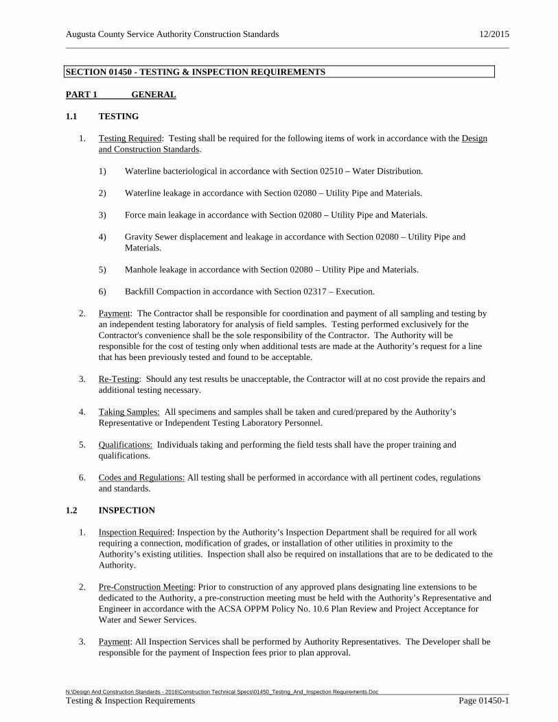
Augusta County Service Authority Construction Standards 12/2015
N:\Design And Construction Standards - 2016\Construction Technical Specs\01450_Testing_And_Inspection Requirements.Doc Testing & Inspection Requirements Page 01450-1
SECTION 01450 - TESTING & INSPECTION REQUIREMENTS
PART 1 GENERAL
1.1 TESTING
1. Testing Required: Testing shall be required for the following items of work in accordance with the Design and Construction Standards.
1) Waterline bacteriological in accordance with Section 02510 – Water Distribution.
2) Waterline leakage in accordance with Section 02080 – Utility Pipe and Materials.
3) Force main leakage in accordance with Section 02080 – Utility Pipe and Materials.
4) Gravity Sewer displacement and leakage in accordance with Section 02080 – Utility Pipe and Materials.
5) Manhole leakage in accordance with Section 02080 – Utility Pipe and Materials.
6) Backfill Compaction in accordance with Section 02317 – Execution.
2. Payment: The Contractor shall be responsible for coordination and payment of all sampling and testing by an independent testing laboratory for analysis of field samples. Testing performed exclusively for the Contractor's convenience shall be the sole responsibility of the Contractor. The Authority will be responsible for the cost of testing only when additional tests are made at the Authority’s request for a line that has been previously tested and found to be acceptable.
3. Re-Testing: Should any test results be unacceptable, the Contractor will at no cost provide the repairs and additional testing necessary.
4. Taking Samples: All specimens and samples shall be taken and cured/prepared by the Authority’s Representative or Independent Testing Laboratory Personnel.
5. Qualifications: Individuals taking and performing the field tests shall have the proper training and qualifications.
6. Codes and Regulations: All testing shall be performed in accordance with all pertinent codes, regulations and standards.
1.2 INSPECTION
1. Inspection Required: Inspection by the Authority’s Inspection Department shall be required for all work requiring a connection, modification of grades, or installation of other utilities in proximity to the Authority’s existing utilities. Inspection shall also be required on installations that are to be dedicated to the Authority.
2. Pre-Construction Meeting: Prior to construction of any approved plans designating line extensions to be dedicated to the Authority, a pre-construction meeting must be held with the Authority’s Representative and Engineer in accordance with the ACSA OPPM Policy No. 10.6 Plan Review and Project Acceptance for Water and Sewer Services.
3. Payment: All Inspection Services shall be performed by Authority Representatives. The Developer shall be responsible for the payment of Inspection fees prior to plan approval.
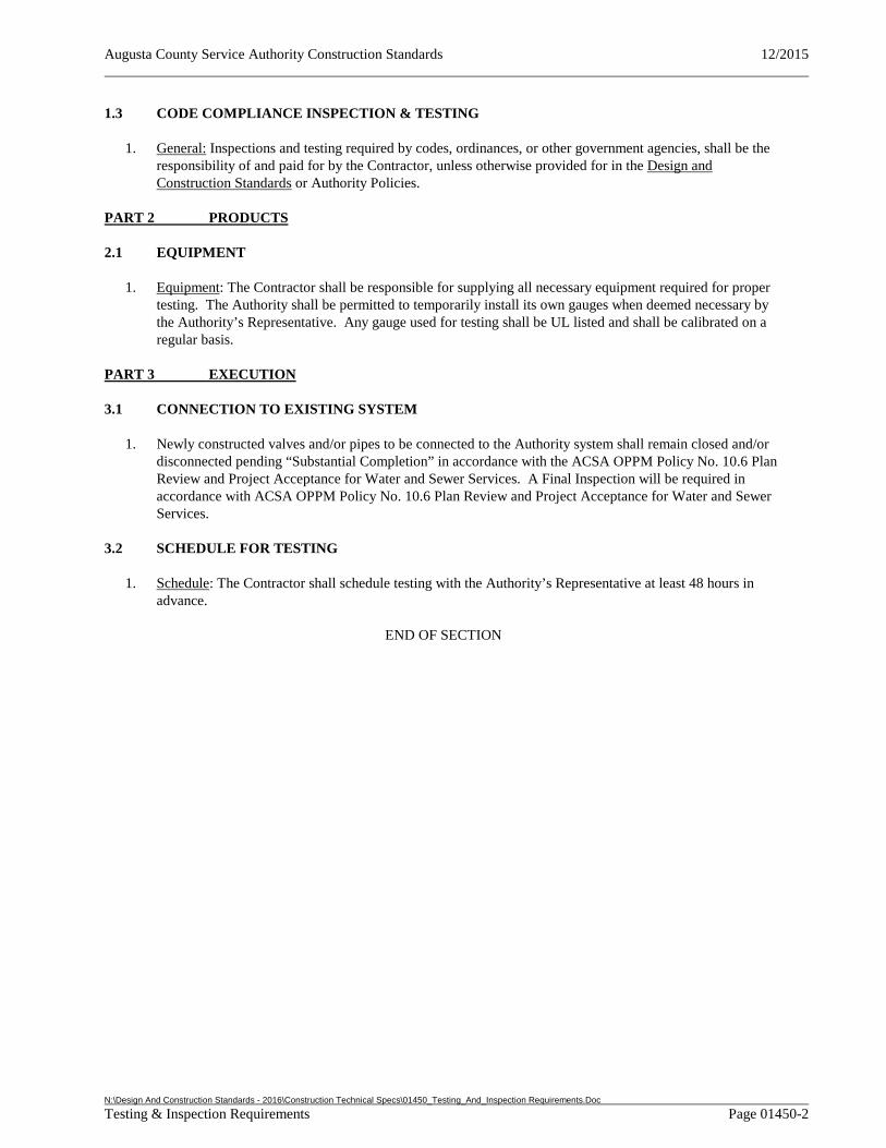
Augusta County Service Authority Construction Standards 12/2015
N:\Design And Construction Standards - 2016\Construction Technical Specs\01450_Testing_And_Inspection Requirements.Doc Testing & Inspection Requirements Page 01450-2
1.3 CODE COMPLIANCE INSPECTION & TESTING
1. General: Inspections and testing required by codes, ordinances, or other government agencies, shall be the responsibility of and paid for by the Contractor, unless otherwise provided for in the Design and Construction Standards or Authority Policies.
PART 2 PRODUCTS
2.1 EQUIPMENT
1. Equipment: The Contractor shall be responsible for supplying all necessary equipment required for proper testing. The Authority shall be permitted to temporarily install its own gauges when deemed necessary by the Authority’s Representative. Any gauge used for testing shall be UL listed and shall be calibrated on a regular basis.
PART 3 EXECUTION
3.1 CONNECTION TO EXISTING SYSTEM
1. Newly constructed valves and/or pipes to be connected to the Authority system shall remain closed and/or disconnected pending “Substantial Completion” in accordance with the ACSA OPPM Policy No. 10.6 Plan Review and Project Acceptance for Water and Sewer Services. A Final Inspection will be required in accordance with ACSA OPPM Policy No. 10.6 Plan Review and Project Acceptance for Water and Sewer Services.
3.2 SCHEDULE FOR TESTING
1. Schedule: The Contractor shall schedule testing with the Authority’s Representative at least 48 hours in advance.
END OF SECTION
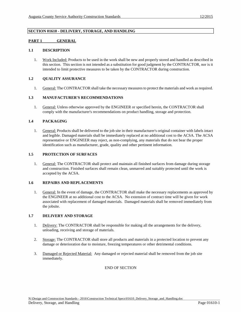
Augusta County Service Authority Construction Standards 12/2015
N:\Design and Construction Standards - 2016\Construction Technical Specs\01610_Delivery_Storage_and_Handling.doc Delivery, Storage, and Handling Page 01610-1
SECTION 01610 - DELIVERY, STORAGE, AND HANDLING
PART 1 GENERAL
1.1 DESCRIPTION
1. Work Included: Products to be used in the work shall be new and properly stored and handled as described in this section. This section is not intended as a substitution for good judgment by the CONTRACTOR, nor is it intended to limit protective measures to be taken by the CONTRACTOR during construction.
1.2 QUALITY ASSURANCE
1. General: The CONTRACTOR shall take the necessary measures to protect the materials and work as required.
1.3 MANUFACTURER'S RECOMMENDATIONS
1. General: Unless otherwise approved by the ENGINEER or specified herein, the CONTRACTOR shall comply with the manufacturer's recommendations on product handling, storage and protection.
1.4 PACKAGING
1. General: Products shall be delivered to the job site in their manufacturer's original container with labels intact and legible. Damaged materials shall be immediately replaced at no additional cost to the ACSA. The ACSA representative or ENGINEER may reject, as non-complying, any materials that do not bear the proper identification such as manufacturer, grade, quality and other pertinent information.
1.5 PROTECTION OF SURFACES
1. General: The CONTRACTOR shall protect and maintain all finished surfaces from damage during storage and construction. Finished surfaces shall remain clean, unmarred and suitably protected until the work is accepted by the ACSA.
1.6 REPAIRS AND REPLACEMENTS
1. General: In the event of damage, the CONTRACTOR shall make the necessary replacements as approved by the ENGINEER at no additional cost to the ACSA. No extension of contract time will be given for work associated with replacement of damaged materials. Damaged materials shall be removed immediately from the jobsite.
1.7 DELIVERY AND STORAGE
1. Delivery: The CONTRACTOR shall be responsible for making all the arrangements for the delivery, unloading, receiving and storage of materials.
2. Storage: The CONTRACTOR shall store all products and materials in a protected location to prevent any damage or deterioration due to moisture, freezing temperatures or other detrimental conditions.
3. Damaged or Rejected Material: Any damaged or rejected material shall be removed from the job site immediately.
END OF SECTION
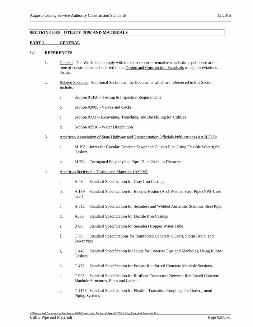
Augusta County Service Authority Construction Standards 12/2015
N:\Design And Construction Standards - 2016\Construction Technical Specs\02080_Utility_Pipe_And_Materials.Doc Utility Pipe and Materials Page 02080-1
SECTION 02080 – UTILITY PIPE AND MATERIALS
PART 1 GENERAL
1.1 REFERENCES
1. General: The Work shall comply with the most recent or tentative standards as published at the time of construction and as listed in the Design and Construction Standards using abbreviations shown.
2. Related Sections: Additional Sections of the Documents which are referenced in this Section Include:
a. Section 01450 – Testing & Inspection Requirements
b. Section 02085 - Valves and Cocks
c. Section 02317- Excavating, Trenching, and Backfilling for Utilities
d. Section 02510 - Water Distribution
3. American Association of State Highway and Transportation Officials Publications (AASHTO):
a. M 198 Joints for Circular Concrete Sewer and Culvert Pipe Using Flexible Watertight Gaskets
b. M 294 Corrugated Polyethylene Pipe 12- to 24-in. in Diameter
4. American Society for Testing and Materials (ASTM):
a. A 48 Standard Specification for Gray Iron Castings
b. A 139 Standard Specification for Electric-Fusion (Arc)-Welded Steel Pipe (NPS 4 and over)
c. A 312 Standard Specification for Seamless and Welded Austenitic Stainless Steel Pipe.
d. A536 Standard Specification for Ductile Iron Casings
e. B 88 Standard Specification for Seamless Copper Water Tube
f. C 76 Standard Specifications for Reinforced Concrete Culvert, Storm Drain, and Sewer Pipe
g. C 443 Standard Specification for Joints for Concrete Pipe and Manholes, Using Rubber Gaskets
h. C 478 Standard Specification for Precast Reinforced Concrete Manhole Sections
i. C 923 Standard Specification for Resilient Connectors Between Reinforced Concrete Manhole Structures, Pipes and Laterals
j. C 1173 Standard Specification for Flexible Transition Couplings for Underground Piping Systems
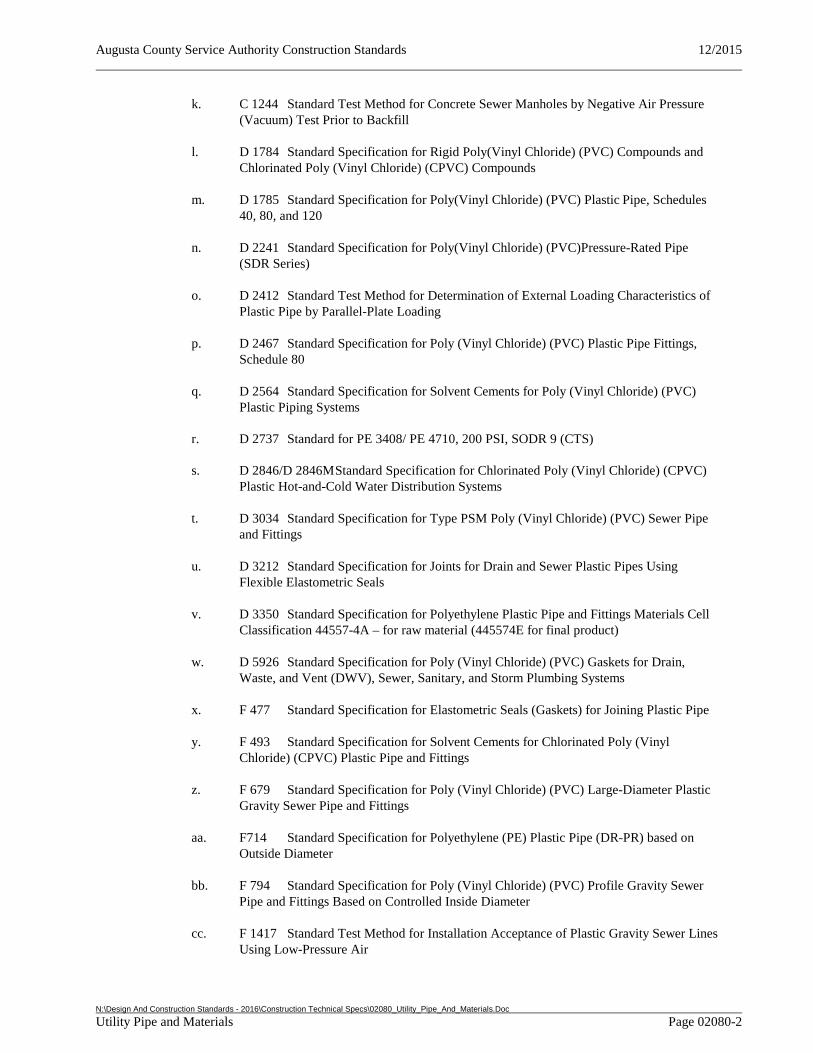
Augusta County Service Authority Construction Standards 12/2015
N:\Design And Construction Standards - 2016\Construction Technical Specs\02080_Utility_Pipe_And_Materials.Doc Utility Pipe and Materials Page 02080-2
k. C 1244 Standard Test Method for Concrete Sewer Manholes by Negative Air Pressure (Vacuum) Test Prior to Backfill
l. D 1784 Standard Specification for Rigid Poly(Vinyl Chloride) (PVC) Compounds and Chlorinated Poly (Vinyl Chloride) (CPVC) Compounds
m. D 1785 Standard Specification for Poly(Vinyl Chloride) (PVC) Plastic Pipe, Schedules 40, 80, and 120
n. D 2241 Standard Specification for Poly(Vinyl Chloride) (PVC)Pressure-Rated Pipe (SDR Series)
o. D 2412 Standard Test Method for Determination of External Loading Characteristics of Plastic Pipe by Parallel-Plate Loading
p. D 2467 Standard Specification for Poly (Vinyl Chloride) (PVC) Plastic Pipe Fittings, Schedule 80
q. D 2564 Standard Specification for Solvent Cements for Poly (Vinyl Chloride) (PVC) Plastic Piping Systems
r. D 2737 Standard for PE 3408/ PE 4710, 200 PSI, SODR 9 (CTS)
s. D 2846/D 2846M Standard Specification for Chlorinated Poly (Vinyl Chloride) (CPVC) Plastic Hot-and-Cold Water Distribution Systems
t. D 3034 Standard Specification for Type PSM Poly (Vinyl Chloride) (PVC) Sewer Pipe and Fittings
u. D 3212 Standard Specification for Joints for Drain and Sewer Plastic Pipes Using Flexible Elastometric Seals
v. D 3350 Standard Specification for Polyethylene Plastic Pipe and Fittings Materials Cell Classification 44557-4A – for raw material (445574E for final product)
w. D 5926 Standard Specification for Poly (Vinyl Chloride) (PVC) Gaskets for Drain, Waste, and Vent (DWV), Sewer, Sanitary, and Storm Plumbing Systems
x. F 477 Standard Specification for Elastometric Seals (Gaskets) for Joining Plastic Pipe
y. F 493 Standard Specification for Solvent Cements for Chlorinated Poly (Vinyl Chloride) (CPVC) Plastic Pipe and Fittings
z. F 679 Standard Specification for Poly (Vinyl Chloride) (PVC) Large-Diameter Plastic Gravity Sewer Pipe and Fittings
aa. F714 Standard Specification for Polyethylene (PE) Plastic Pipe (DR-PR) based on Outside Diameter
bb. F 794 Standard Specification for Poly (Vinyl Chloride) (PVC) Profile Gravity Sewer Pipe and Fittings Based on Controlled Inside Diameter
cc. F 1417 Standard Test Method for Installation Acceptance of Plastic Gravity Sewer Lines Using Low-Pressure Air
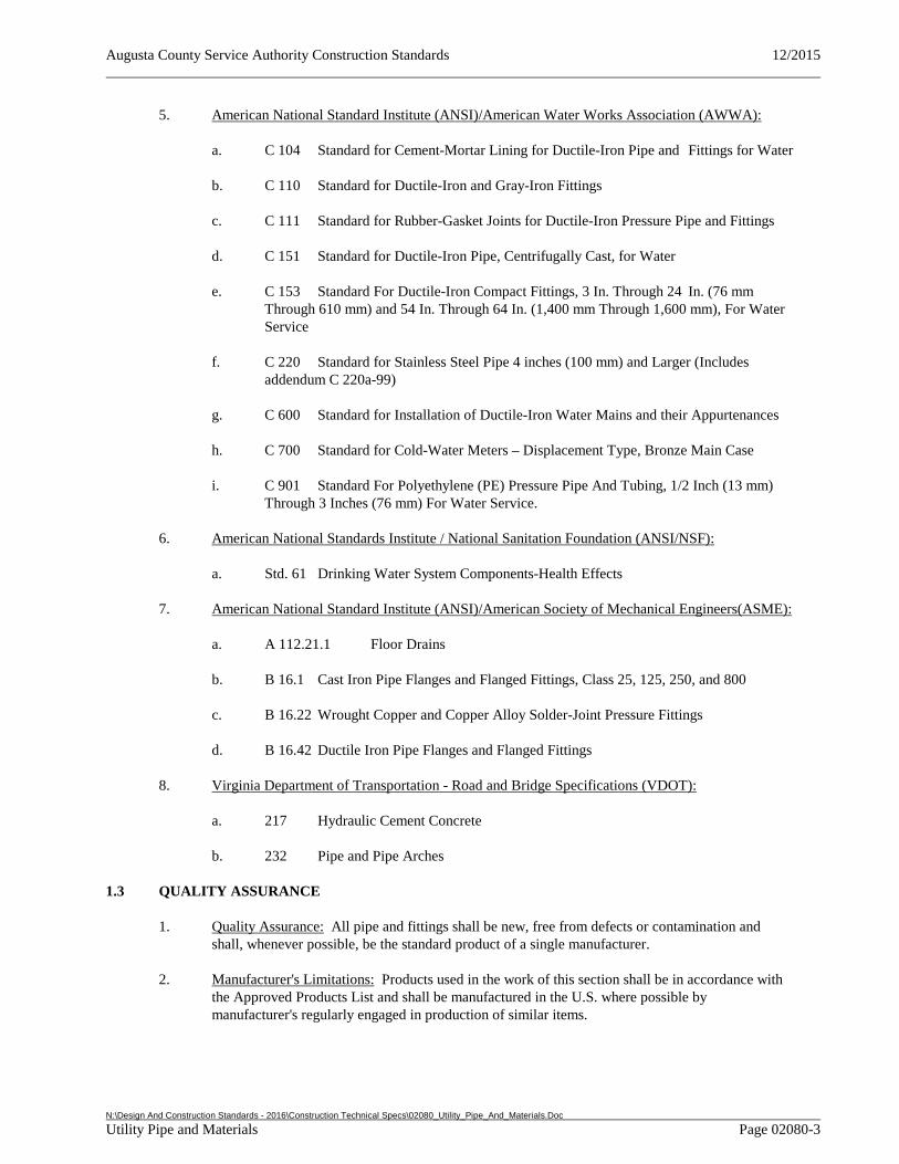
Augusta County Service Authority Construction Standards 12/2015
N:\Design And Construction Standards - 2016\Construction Technical Specs\02080_Utility_Pipe_And_Materials.Doc Utility Pipe and Materials Page 02080-3
5. American National Standard Institute (ANSI)/American Water Works Association (AWWA):
a. C 104 Standard for Cement-Mortar Lining for Ductile-Iron Pipe and Fittings for Water
b. C 110 Standard for Ductile-Iron and Gray-Iron Fittings
c. C 111 Standard for Rubber-Gasket Joints for Ductile-Iron Pressure Pipe and Fittings
d. C 151 Standard for Ductile-Iron Pipe, Centrifugally Cast, for Water
e. C 153 Standard For Ductile-Iron Compact Fittings, 3 In. Through 24 In. (76 mm Through 610 mm) and 54 In. Through 64 In. (1,400 mm Through 1,600 mm), For Water Service
f. C 220 Standard for Stainless Steel Pipe 4 inches (100 mm) and Larger (Includes addendum C 220a-99)
g. C 600 Standard for Installation of Ductile-Iron Water Mains and their Appurtenances
h. C 700 Standard for Cold-Water Meters – Displacement Type, Bronze Main Case
i. C 901 Standard For Polyethylene (PE) Pressure Pipe And Tubing, 1/2 Inch (13 mm) Through 3 Inches (76 mm) For Water Service.
6. American National Standards Institute / National Sanitation Foundation (ANSI/NSF):
a. Std. 61 Drinking Water System Components-Health Effects
7. American National Standard Institute (ANSI)/American Society of Mechanical Engineers(ASME):
a. A 112.21.1 Floor Drains
b. B 16.1 Cast Iron Pipe Flanges and Flanged Fittings, Class 25, 125, 250, and 800
c. B 16.22 Wrought Copper and Copper Alloy Solder-Joint Pressure Fittings
d. B 16.42 Ductile Iron Pipe Flanges and Flanged Fittings
8. Virginia Department of Transportation - Road and Bridge Specifications (VDOT):
a. 217 Hydraulic Cement Concrete
b. 232 Pipe and Pipe Arches
1.3 QUALITY ASSURANCE
1. Quality Assurance: All pipe and fittings shall be new, free from defects or contamination and shall, whenever possible, be the standard product of a single manufacturer.
2. Manufacturer's Limitations: Products used in the work of this section shall be in accordance with the Approved Products List and shall be manufactured in the U.S. where possible by manufacturer's regularly engaged in production of similar items.
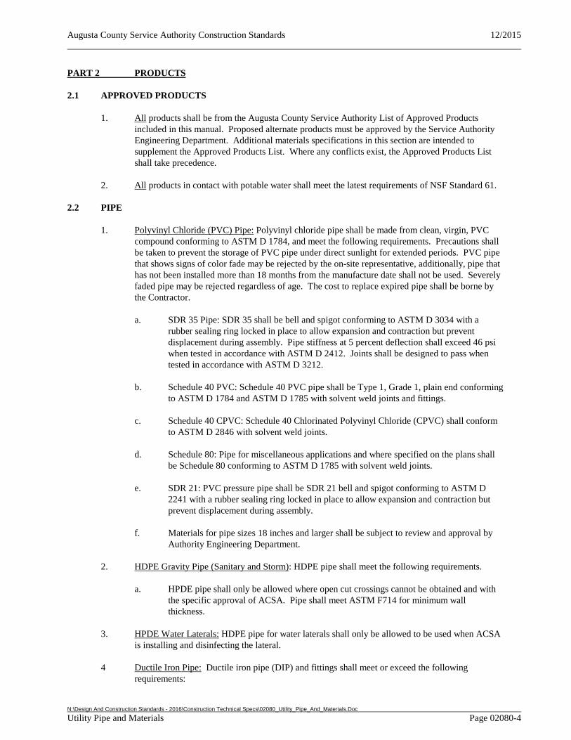
Augusta County Service Authority Construction Standards 12/2015
N:\Design And Construction Standards - 2016\Construction Technical Specs\02080_Utility_Pipe_And_Materials.Doc Utility Pipe and Materials Page 02080-4
PART 2 PRODUCTS
2.1 APPROVED PRODUCTS
1. All products shall be from the Augusta County Service Authority List of Approved Products included in this manual. Proposed alternate products must be approved by the Service Authority Engineering Department. Additional materials specifications in this section are intended to supplement the Approved Products List. Where any conflicts exist, the Approved Products List shall take precedence.
2. All products in contact with potable water shall meet the latest requirements of NSF Standard 61.
2.2 PIPE
1. Polyvinyl Chloride (PVC) Pipe: Polyvinyl chloride pipe shall be made from clean, virgin, PVC compound conforming to ASTM D 1784, and meet the following requirements. Precautions shall be taken to prevent the storage of PVC pipe under direct sunlight for extended periods. PVC pipe that shows signs of color fade may be rejected by the on-site representative, additionally, pipe that has not been installed more than 18 months from the manufacture date shall not be used. Severely faded pipe may be rejected regardless of age. The cost to replace expired pipe shall be borne by the Contractor.
a. SDR 35 Pipe: SDR 35 shall be bell and spigot conforming to ASTM D 3034 with a rubber sealing ring locked in place to allow expansion and contraction but prevent displacement during assembly. Pipe stiffness at 5 percent deflection shall exceed 46 psi when tested in accordance with ASTM D 2412. Joints shall be designed to pass when tested in accordance with ASTM D 3212.
b. Schedule 40 PVC: Schedule 40 PVC pipe shall be Type 1, Grade 1, plain end conforming to ASTM D 1784 and ASTM D 1785 with solvent weld joints and fittings.
c. Schedule 40 CPVC: Schedule 40 Chlorinated Polyvinyl Chloride (CPVC) shall conform to ASTM D 2846 with solvent weld joints.
d. Schedule 80: Pipe for miscellaneous applications and where specified on the plans shall be Schedule 80 conforming to ASTM D 1785 with solvent weld joints.
e. SDR 21: PVC pressure pipe shall be SDR 21 bell and spigot conforming to ASTM D 2241 with a rubber sealing ring locked in place to allow expansion and contraction but prevent displacement during assembly.
f. Materials for pipe sizes 18 inches and larger shall be subject to review and approval by Authority Engineering Department.
2. HDPE Gravity Pipe (Sanitary and Storm): HDPE pipe shall meet the following requirements.
a. HPDE pipe shall only be allowed where open cut crossings cannot be obtained and with the specific approval of ACSA. Pipe shall meet ASTM F714 for minimum wall thickness.
3. HPDE Water Laterals: HDPE pipe for water laterals shall only be allowed to be used when ACSA is installing and disinfecting the lateral.
4 Ductile Iron Pipe: Ductile iron pipe (DIP) and fittings shall meet or exceed the following requirements:
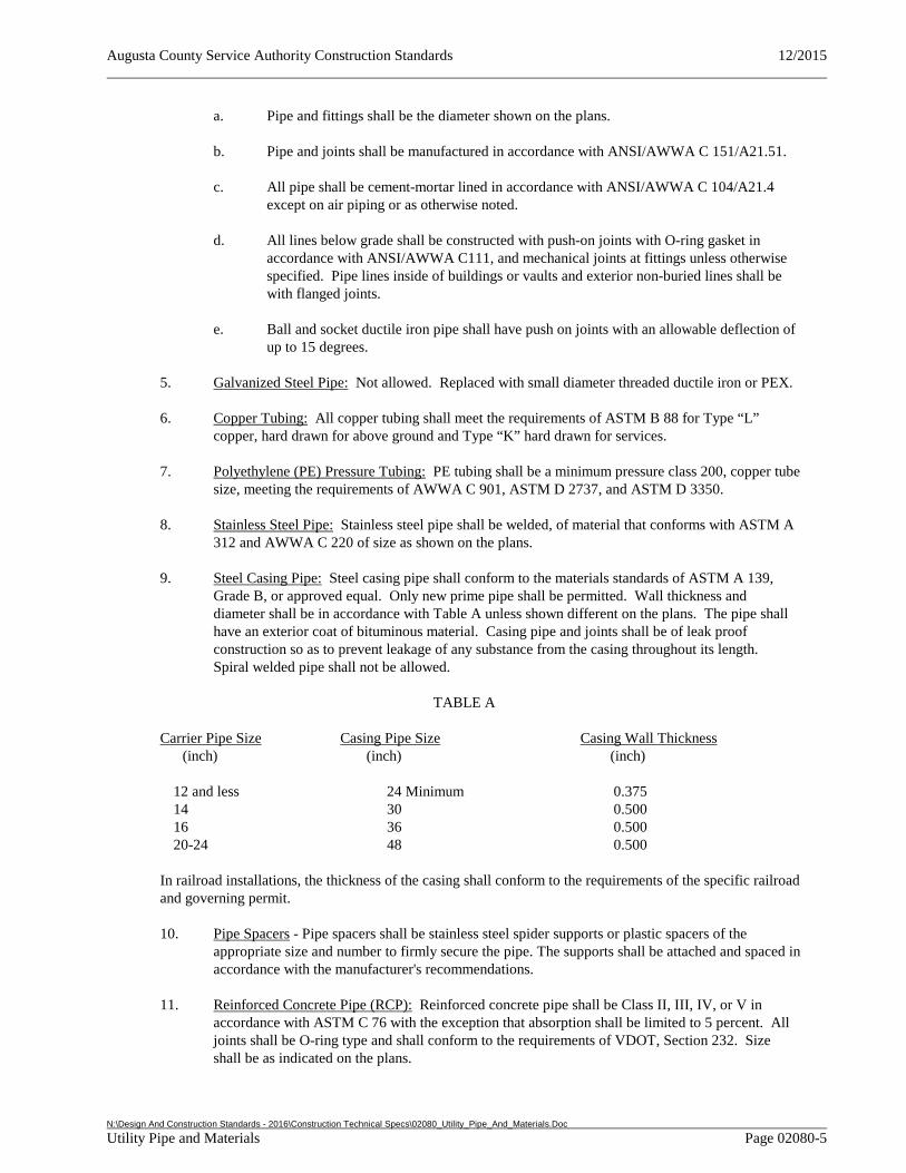
Augusta County Service Authority Construction Standards 12/2015
N:\Design And Construction Standards - 2016\Construction Technical Specs\02080_Utility_Pipe_And_Materials.Doc Utility Pipe and Materials Page 02080-5
a. Pipe and fittings shall be the diameter shown on the plans.
b. Pipe and joints shall be manufactured in accordance with ANSI/AWWA C 151/A21.51.
c. All pipe shall be cement-mortar lined in accordance with ANSI/AWWA C 104/A21.4 except on air piping or as otherwise noted.
d. All lines below grade shall be constructed with push-on joints with O-ring gasket in accordance with ANSI/AWWA C111, and mechanical joints at fittings unless otherwise specified. Pipe lines inside of buildings or vaults and exterior non-buried lines shall be with flanged joints.
e. Ball and socket ductile iron pipe shall have push on joints with an allowable deflection of up to 15 degrees.
5. Galvanized Steel Pipe: Not allowed. Replaced with small diameter threaded ductile iron or PEX.
6. Copper Tubing: All copper tubing shall meet the requirements of ASTM B 88 for Type “L” copper, hard drawn for above ground and Type “K” hard drawn for services.
7. Polyethylene (PE) Pressure Tubing: PE tubing shall be a minimum pressure class 200, copper tube size, meeting the requirements of AWWA C 901, ASTM D 2737, and ASTM D 3350.
8. Stainless Steel Pipe: Stainless steel pipe shall be welded, of material that conforms with ASTM A 312 and AWWA C 220 of size as shown on the plans.
9. Steel Casing Pipe: Steel casing pipe shall conform to the materials standards of ASTM A 139, Grade B, or approved equal. Only new prime pipe shall be permitted. Wall thickness and diameter shall be in accordance with Table A unless shown different on the plans. The pipe shall have an exterior coat of bituminous material. Casing pipe and joints shall be of leak proof construction so as to prevent leakage of any substance from the casing throughout its length. Spiral welded pipe shall not be allowed.
TABLE A
Carrier Pipe Size Casing Pipe Size Casing Wall Thickness (inch) (inch) (inch)
12 and less 24 Minimum 0.375 14 30 0.500 16 36 0.500 20-24 48 0.500
In railroad installations, the thickness of the casing shall conform to the requirements of the specific railroad and governing permit.
10. Pipe Spacers - Pipe spacers shall be stainless steel spider supports or plastic spacers of the appropriate size and number to firmly secure the pipe. The supports shall be attached and spaced in accordance with the manufacturer's recommendations.
11. Reinforced Concrete Pipe (RCP): Reinforced concrete pipe shall be Class II, III, IV, or V in accordance with ASTM C 76 with the exception that absorption shall be limited to 5 percent. All joints shall be O-ring type and shall conform to the requirements of VDOT, Section 232. Size shall be as indicated on the plans.
Augusta County Service Authority Construction Standards 12/2015
N:\Design And Construction Standards - 2016\Construction Technical Specs\02080_Utility_Pipe_And_Materials.Doc Utility Pipe and Materials Page 02080-6
2.3 FITTINGS
1. Polyvinyl Chloride (PVC) Fittings: Polyvinyl chloride fittings shall be made from clean, virgin, PVC compound conforming to ASTM D 1784 and shall conform to the following requirements:
a. Gravity Sewer: Fittings shall be gasketed bell type conforming to ASTM D 3034 for SDR 35.
b. Drain, Waste, and Vent: Fittings shall be Schedule 40 socket type conforming to ASTM D 2467.
c. Solvent Cement: Solvent cement for use on PVC pipe and fittings shall conform to ASTM F 493 ASTM D 2564, or ASTM D 2846 as appropriate for pipe used.
2. Ductile Iron Fittings: Ductile iron fittings shall be lined and seal coated in accordance with ANSI/AWWA C 104/A21.04, and shall be manufactured in accordance with ANSI/AWWA C 110/A21.10 for standard body and ANSI/AWWA C 153/A21.53 for compact body fittings, and meet the following requirements:
a. Buried fittings shall be mechanical joint and supplied with the proper adapter and/or transition gasket for use with PVC pipe. Buried fittings shall be rated for a working pressure of 350 psi.
b. Flanged fittings shall be 125 pound fittings meeting ANSI/ASME B 16.42, or meeting ANSI/ASME B 16.1 for fittings not available in ductile iron.
3. Copper Pipe Fittings: Fittings shall meet requirements of ANSI/ASME B 16.22 for wrought copper, sweat joint.
4. Pressure Tubing Fittings: Couplings and fittings for copper or polyethylene pressure tubing shall be bronze compression type.
5. Couplings:
a. Gravity sewer pipe: Couplings for use in joining gravity pipe of differing materials and/or sizes shall push on type.
b. Pressure pipe: Connections between DIP to PVC pressure pipe shall be done with regular ductile iron mechanical joint sleeves.
6. Restrained Joint Fittings: Restrained joints shall be used with mechanical retainer glands. Dimensions of the glands shall be such that they can be used with the standardized mechanical joint bell and tee head bolts conforming to the requirements of AWWA C 111 and AWWA C 153.
a. Push On Joint Pipe: If push-on joint pipe is used, restraining mechanisms shall be a contoured wedge-action retainer gland installed on the spigot (plain) end of the pipe, connected to a standard mechanical joint gland seated behind the pipe bell or internal restraining gaskets. Mark all bells with warning type when restraining gaskets are used. Restraint devices shall meet the applicable requirements of ANSI/AWWA C111/A21.11-12 and ASTM A536.
Augusta County Service Authority Construction Standards 12/2015
N:\Design And Construction Standards - 2016\Construction Technical Specs\02080_Utility_Pipe_And_Materials.Doc Utility Pipe and Materials Page 02080-7
7. High Density Polyethylene Fittings (Smooth Bore Pipe): Fittings shall conform to AASHTO M 294. Fabricated fittings shall be welded on the interior and exterior at all junctions.
2.4 WATER METERS
1. All meters for billing purposes shall be supplied by the Authority once all connection fees have been paid or permit for temporary meter has been obtained.
All meter assemblies shall be constructed in accordance with these Design and Construction Standards, and shall be of the type and manufacturer approved by the Service Authority Engineering Department.
2.5 METER BOXES & VAULTS
1. Meter Box & Cover: Each meter shall be installed in a meter box conforming to the Approved Products and applicable Standard Details. Each meter box shall be equipped with a locking, traffic bearing where necessary, frame and cover. Lid shall accommodate reading system utilized by the Service Authority.
2. Meter Vault: Pre-cast vaults shall be provided by the contractor for meters 3 inches and larger. Minimum dimensions and special details shall be as shown on the Standard Detail. Joints on precast unit shall be sealed with an asphaltic butyl compound to make them watertight. Vault and hatch shall be traffic rated (H20) unless otherwise approved.
2.6 MANHOLES
1. General: Concrete manholes shall be of precast construction. Items delivered and installed at the site shall be structurally sound and free from cracks or major surface blemishes. Manholes not complying with this or these Standards as determined by the Authority’s Representative will not be accepted/approved by the Authority.
2. Under no circumstances shall manholes or other structures be left in an incomplete condition such that surface water could enter into the sewer line. This constitutes a violation of the Service Authority’s inflow and infiltration prohibitions and may be subject to fines.
3. Construction:
a. Precast manholes shall conform to ASTM C 478 and the Standard Details. Drop manholes where required shall be constructed in accordance with the Standard Detail. Monolithic bottoms with extended base may be required in unstable soil conditions or where floatation may be a problem.
b. The eccentric design manhole shall be used, except as otherwise approved and shown on the plans.
c. Manholes larger than minimum size may be required where pipe deflection or intersection of two or more upstream lines occur. All manholes shall have monolithic bases.
4. Precast Inverts: The invert channels shall be precast with concrete monolithically with the base as shown on the Standard Details and shall be smooth and semi-circular in shape, conforming to the inside of the adjacent sewer section. Channel inverts shall be constructed to provide a smooth continuous positive slope between pipes. Changes in direction of flow (horizontally and vertically) shall be made with a smooth curve of as large a radius as size of the manhole will permit as shown on the Standard Detail. The floor (bench) of the manhole outside of the channels shall be smooth
Augusta County Service Authority Construction Standards 12/2015
N:\Design And Construction Standards - 2016\Construction Technical Specs\02080_Utility_Pipe_And_Materials.Doc Utility Pipe and Materials Page 02080-8
and shall slope toward the channels not less than 2 inches per foot or more than 4 inches per foot. Inverts shall be sloped no less than 2 percent across manhole base.
5. Manhole Steps: Manhole steps shall be polypropylene-coated steel reinforcing bar with a minimum design live load of 300 lbs and shall be provided in all manholes in accordance with the Standard Detail. The steps shall be of non-slip type approved by OSHA.
6. Pipe Connections:
a. Existing lines shall be installed with a flexible pipe to manhole connector/boot. When connections are made to existing manholes, invert shaping shall be modified by the Contractor to accommodate new connection.
b. New sewer line pipe including services shall be connected to the manhole base section with an integrally cast approved flexible water-tight connector/boot and all-stainless steel take up clamps in accordance with ASTM C 923. Points of entry for mains or services which are added after fabrication of the manhole shall be provided by machine coring and installation of a flexible connector. The connector shall be installed in the manhole wall by activating the expanding mechanism in strict accordance with the manufacturer's recommendations.
c. All pipes shall extend through the manhole walls a minimum of two inches. Chipping, jacking, or breaking of concrete to make connections is prohibited. Any such occurrences shall be repaired at the expense of the Contractor.
d. The connector shall be of a size specifically designed for the pipe size and material being utilized on the project.
7. Sewer Pump/Force Main Receiving Manholes: Interior of new and existing force main receiving manholes shall receive an epoxy coating. Coating shall be 100 percent solids based epoxy binder combined with fibrous and flake fillers to minimize water vapor transmission and increase flexural strength. Material shall be specifically designed for manhole rehabilitation. Coating shall be corrosion resistant. Material shall be applied at 40-60 mils thick on vertical and overhead surfaces.
8. Frames and Covers: Frames and covers shall be of cast iron conforming to ASTM A 48 for Class 30 Gray Iron. Castings shall be of uniform quality, free from sand holes, gas holes, shrinkage, cracks, and other surface defects. Castings shall be ground smooth and well cleaned by shot blasting. For traffic service castings, bearing surfaces between cover and frame shall be cast or machined with such precision to prevent rocking. Bolt holes for watertight frames and covers shall be cast into the unit at the time of manufacturing to insure proper alignment of holes between frame and cover no matter how the cover is oriented on the frame.
Standard and watertight frame and covers shall conform to the Standard Details.
a. The frame and cover shall be sealed to the outside of the concrete manhole section with a double ring of butyl sealant/rope and bolted to the manhole in accordance with the Standard Details.
b. Height control rings may be used to adjust manhole tops to proper grade, however, a maximum of 12 inches total height of control rings will be permitted.
9. Concrete: A submittal must be provided for concrete used for shaping of manholes, channels, and miscellaneous work. Concrete shall have a minimum break strength of 2,500 psi. For shaping, hydraulic cement shall be used.
Augusta County Service Authority Construction Standards 12/2015
N:\Design And Construction Standards - 2016\Construction Technical Specs\02080_Utility_Pipe_And_Materials.Doc Utility Pipe and Materials Page 02080-9
10. Joints: Joints shall be sealed with two rings of butyl rubber rope or O-ring conforming to AASHTO M 198, Type B.
11. Vented Manholes: Vented manholes shall conform to the Standard Detail.
2.7 MISCELLANEOUS DEVICES
1. Floor Drains: Drains shall conform to ANSI/ASME A 112.21.1. Floor drains shall be coated cast iron with double drainage flange, weepholes, threaded outlet connection, integral bell trap, and adjustable polished nickel alloy round removable strainer. Strainer shall be 6 inches in diameter and shall be made with light duty grate in buildings except in traffic areas where medium duty shall be used.
2. Pressure Gauges: Pressure gauges shall be bronze Bourdon tube in cast aluminum case with male 1/4 inch IPT connection at bottom, at least 4 1/2 inch face diameter with a range adequate to measure all working pressures, installed with brass piston type pulsation dampener. Gauges on the suction side of pumps shall be a pressure and vacuum gauge with a range adequate to measure all working pressures. Each gauge shall be mounted with a bronze ball cock to allow removal or servicing and a piston type pressure snubber to protect the gauge from rapid changes in line pressure. Gauges for use in wastewater applications shall be isolated from direct contact with wastewater by means of a diaphram type isolator.
3. Pipe Repair Clamps: Shall be of ductile or stainless steel, type 304 with pre-assembled stainless steel bolting mechanism.
4. Tapping Saddles: Saddles shall be made of a malleable material and have flat stainless steel straps. Rubber gaskets shall be required for all pipe sizes and classes. Lead gaskets are prohibited. Saddles shall provide full support around the circumference of the pipe and have a bearing area of sufficient width along the axis of the pipe 1-1/2 inch minimum. Saddles shall not have lugs that will dig into the pipe when the saddle is tightened. The U-bolt type strap will not be allowed.
5. Sewer Connection Saddle/Connections: On existing lines connections shall be made with an insertion tee or a saddle. Saddle shall be attached to the main line by a stainless steel strap and have water tight seal to both the main line and the branch outlet.
PART 3 EXECUTION
3.1 EXCAVATION, BACKFILLING AND COMPACTION
1. General: Trench excavation shall be in accordance with Section 02317 – Excavation, Trenching, and Backfilling for Utilities
3.2 SEPARATION OF WATER AND SEWER LINES
1. Parallel Installation:
a. Normal conditions – Water mains shall be separated at least 10 feet horizontally (measured edge to edge) from a sewer or sewer manhole. The distance shall be measured edge-to-edge. All water and sewer lines shall be installed a minimum of 20 feet from structures, including but not limited to, buildings, columns, and signs. Sewer lines and wells shall be a minimum of 50 feet away from any potable water well.
b. Unusual conditions – When local conditions prevent a horizontal separation of 10 feet, the Contractor shall notify the Authority’s Representative. The Authority’s
Augusta County Service Authority Construction Standards 12/2015
N:\Design And Construction Standards - 2016\Construction Technical Specs\02080_Utility_Pipe_And_Materials.Doc Utility Pipe and Materials Page 02080-10
Representative, after consultation with the Virginia Department of Health, shall provide special instructions for construction within the area of conflict. In some cases, if authorized by the Authority’s Representative, the 10 foot separation requirement may be waived provided that:
c. The bottom (invert) of the water main shall be at least 18 inches above the top (crown) of the sewer.
d. Where this vertical separation cannot be obtained, the sewer shall be constructed of AWWA approved water pipe, pressure tested in place to 30 psi without leakage prior to backfilling.
e. The sewer manhole shall be of watertight construction and tested in place.
2. Crossings:
a. Normal conditions – Water lines crossing over sewers shall have a separation of at least 18 inches between the bottom of the water line and the top of the sewer.
b. Unusual conditions – When local conditions prevent a vertical separation described above, the Contractor shall notify the Authority’s Representative. The Authority’s Representative, after consultation with the Virginia Department of Health, shall provide special instructions for construction within the area of conflict. In some cases, if authorized by the Authority’s Representative, the following construction shall be used:
i. Sewers passing over or under water mains shall be constructed of AWWA approved water pipe, pressure tested in place to 30 psi without leakage prior to backfilling. Sewer pipe shall also be centered at the point of water line crossing such that the joints are equidistant from the crossing.
ii. Water lines passing under sewers shall, in addition, be protected by providing:
• A vertical separation of at least 18 inches between the bottom of the sewer and the top of the water line.
• Adequate structural support for the sewers to prevent excessive deflection of the joints and the settling on and breaking of the waterline.
• That the length of the water line be centered at the point of the crossing so that joints shall be equidistant and as far as possible from the crossing.
3. Intersections: No water pipe shall pass through or come in contact with any part of the sewer or sewer manhole. Nor shall any water distribution flushing device be directly connected to any sewer.
4. Special Cases: In the event that existing utilities or field conditions make it impossible or impractical to meet the separation requirements, the Contractor shall notify the Authority’s Representative. The Authority’s Representative, after consultation with the Virginia Department of Health, shall provide special instructions for construction within the area of conflict (likely to include installation of a sleeve on the lateral).
5. Storm Sewers: Where possible, all storm sewers shall maintain 18” of separation. Where other conflicts prevent this separation, concrete cradles supporting the waterline on both sides of the
Augusta County Service Authority Construction Standards 12/2015
N:\Design And Construction Standards - 2016\Construction Technical Specs\02080_Utility_Pipe_And_Materials.Doc Utility Pipe and Materials Page 02080-11
storm sewer may be required. No water pipe shall pass through or come in contact with any part of the storm sewer or storm sewer manhole.
3.3 INSTALLATION OF PIPE AND FITTINGS
1. General: No valve, hydrant, or other appurtenance on existing water lines shall be opened or closed for any purpose by the Contractor. Any opening or closing of valves, hydrants, whatsoever shall be by the Authority only. The Contractor shall notify the Authority at least 48 hours prior to the need to open or close any appurtenance, except in emergencies, at which time the Authority shall be notified immediately.
2. Depth and Cover: All water lines shall be constructed with a properly prepared trench, pipe bedding, and backfill. All water lines shall have a minimum of 42-inch and maximum of 60-inch cover measured from the top of the pipe to the finished grade at the proposed pipe centerline. Only under extraordinary circumstances and with special permission of the Authority shall water lines be deeper than 60 inches, or less than 42-inches deep (see Standard Detail).
3. Slope: When installing gravity sewer on slopes of less than one percent, laser technology shall be used to insure proper grades.
4. Handling: Pipe shall be placed in the trench in such a manner as to prevent damage to pipe and protective coatings and linings. Under no circumstances shall pipe be dropped or dumped into the trench. As the temperature approaches or drops below freezing, extra care shall be used in handling pipe.
5. Cleaning: Every precaution shall be taken to prevent foreign material from entering the pipe while it is being placed in the line. Spigot and bell ends of pipe and gaskets shall be cleaned and lubricated according to manufacturer's instructions. If the pipe cannot be placed without getting debris into it, the Authority may require that a heavy tightly woven canvas bag of suitable size be placed over each end of the pipe before lowering the pipe into the trench and left there until the connection is made to the adjacent pipe. At times when pipe laying is not in progress, the open ends of the pipe shall be closed by a watertight plug. If water accumulates in the trench, plugs shall remain in place until the trench is dry.
6. Cutting: Pipe shall be cut in a neat and workmanlike manner without damage to the pipe. Unless otherwise authorized by the Authority’s Representative, cutting shall be done by means of approved type of mechanical cutters. Wheel cutters shall be used when practicable. Use of oxy-acetelyne torch or similar method to cut pipe will not be permitted.
7. Direction of Laying: All pipe shall be laid with bell ends facing in the direction of laying unless otherwise directed by the Authority’s Representative. Where pipe is laid on a grade of 10 percent or greater, or for gravity pipe systems, the laying shall start at bottom and shall proceed upward with the bell ends of pipe upgrade. Each piece of pipe shall be laid true to line and grade. The bottom of the trench shall be smoothly graded and bell holes provided so that the trench bottom provides uniform support to the barrel of the pipe when in final position. Adjustments to line or grade shall be made by removing or adding granular material under the barrel. In no case shall wedges or blocks be used under the body of the pipe. The pipe shall be pushed fully "home" by hand, with a bar and block of wood to cushion the bell, or other similar methods for large diameter pipe.
8. Bedding: Bedding of pipe shall be placed to the depth shown on the plans or standard details and shall be compacted to specified density. Bedding of ductile iron pressure pipe shall consist of firm subgrade with excavation for bell holes. When in rock excavation or for gravity sewer, bedding shall consist of a gravel base as shown in the Standard Details.
Augusta County Service Authority Construction Standards 12/2015
N:\Design And Construction Standards - 2016\Construction Technical Specs\02080_Utility_Pipe_And_Materials.Doc Utility Pipe and Materials Page 02080-12
9. Lateral Connections: In-Line wyes and tees for cleanouts/laterals shall be installed during initial construction. When lines are required to be tapped, connections shall be made using an approved watertight saddle.
10. Stubouts: Stubouts when required shall be extended a minimum of 10 feet beyond the existing or proposed edge of pavement or as indicated on the plans.
11. Deflection at Joints: Maximum deflection for force main and pressure pipe joints will be as follows:
Allowable Deflection (in inches)
Pipe Size
Ductile Iron (Push on) Lengths
12' 16' 18' 20'
Ductile Iron (Mechanical)
Lengths 12' 16' 18' 20'
4" 12 17 19 21 21 28 31 34 6" 12 17 19 21 18 24 27 30 8" 12 17 19 21 13 18 20 22 12" 12 17 19 21 13 18 20 22 16" 7.5 10 11 12 9 12 13.5 15
12. Installation of Fittings: Fittings shall be installed with the same care that mainline pipe is installed.
Caps or plugs shall be braced to prevent blow off during testing.
13. Jointing:
a. Mechanical Joints: When installing mechanical joint (MJ) ductile iron pipe, the socket, spigot end and rubber gasket shall be thoroughly washed with soapy water to remove any grease or grit that might damage the gasket. In making up the joint, the gland for MJ pipe followed by the gasket, shall be placed over the plain end of the pipe and inserted into the socket. The gasket shall be pushed into position without excessive force and evenly seated in the socket of the pipe bell, and the gland for MJ pipe, then moved into position against the face of the rubber gasket.
b. Flanged Joints: Where flanged joints are used, they shall be installed by skilled workmen in accordance with the best standard practice. Bolts shall be tightened in accordance with the manufacturer’s requirements to evenly distribute the joint stress and insure proper pipe alignment.
c. Roadway and Railroad Crossings through Casings: When conditions require use of casings, care shall be taken to maintain the proposed plan grade. Before pushing the pipe through the casing, spiders shall be strapped to the pipe, in accordance with manufacturer’s recommendations, to keep the pipe centered in the casing and to prevent damage when installation is made. Care shall be taken to ensure that the installed pipeline is well secured to prevent movement. See Standard Detail.
Construction of bores shall be carried out in such a manner that there will be no settlement of the ground surface above the bores. The contractor will be responsible for all settlements above the bore. Bores shall be made such that they will not be off line more than amount equal to one (1) percent of the length of the bore, not to exceed two (2) feet. Bores will not be off grade more than one (1) percent, not to exceed 0.5 ft. Where the casing pipe is not installed in accordance with the elevations, grade or alignment indicated, any deviations shall be subject to the approval of the Authority. Approval of
Augusta County Service Authority Construction Standards 12/2015
N:\Design And Construction Standards - 2016\Construction Technical Specs\02080_Utility_Pipe_And_Materials.Doc Utility Pipe and Materials Page 02080-13
the installation will not be given, if in the opinion of the Authority the required adjustments of the system will not conform to the Authority's design criteria.
All joints within casing pipe shall be restrained in accordance with the Standard Detail.
Installation of pipeline and casing pipe by boring shall be performed by individuals or companies experienced in such construction. Properly shored boring and receiving pits shall be installed at the ends of the bore. The bore shall proceed as rapidly as possible to prevent seizing to the casing pipe. Lengths of casing pipe shall be welded at all joints to the section previously installed. The end of the casing pipe shall be sealed in accordance with the Standard Detail.
The operations shall be conducted in a manner to prevent voids between the surface of the casing and the earth. Casing pipe shall be backfilled using crusher run stone.
A boring plan and product data for casing and spacers shall be submitted for approval prior to commencement of work.
Railroad crossings shall be in accordance with all railroad permits and standards as required.
d. Installation of Tees and Laterals: Tees and laterals shall be installed with the same care that mainline sewers are laid. Slopes shall be not less than 1 percent unless otherwise indicated. Laterals shall be the same material as the main sewer pipe and shall run to property lines unless otherwise indicated on the plans. Laterals shall be properly capped and suitably sealed to prevent infiltration of water into the connections. Caps or plugs shall be braced to prevent blowoff during exfiltration or air testing. Couplings shall be provided as needed for ductile iron pipe connections to plastic tees. Rotation of mainlines and concrete support will be required for deeper installations. Cleanouts per the appropriate detail shall be provided at the terminal points.
14. Installation of Manhole Stubouts: Manhole stubouts shall be provided where indicated. Stubout pipe shall be 8 inch diameter unless otherwise indicated on the plans and shall be the same pipe material as the sewer pipe. Manhole stubouts shall be extended from the manhole a minimum of 10 feet beyond the existing or proposed edge of pavement or as shown on the plans. Stubouts shall be sealed with a pipe cap or plug to prevent infiltration.
15. Cleanouts: Piping and fittings shall be constructed of the same materials as the main line sewer and shall conform to the Standard Detail. Reconnecting to existing laterals shall be accomplished with proper water tight transition couplings as required.
16. Water Service Connections:
a. Existing Waterlines: New service taps on existing water lines shall be made under pressure with proper tapping machine for the pipe being tapped and with the Authority’s Representative present.
b. New Water Lines: New service taps on new water lines may be made prior to the line being filled. The water main shall be tested, disinfected, and thoroughly flushed after service taps are made. Taps shall not be backfilled until pressure testing is complete or following consultation with Authority’s Representative.
17. Setting of Valves: Valves shall be installed in accordance with manufacturer's instructions and shall be in accordance with Section 02085 - Valves and Cocks and as shown on the Standard Details.
Augusta County Service Authority Construction Standards 12/2015
N:\Design And Construction Standards - 2016\Construction Technical Specs\02080_Utility_Pipe_And_Materials.Doc Utility Pipe and Materials Page 02080-14
18. Anchorage and Joint Restraint: For pipe installation at grades over 20 percent, the pipe shall be anchored in accordance with the Standard Detail. Where required, pressure pipe lines shall be restrained by suitable joint restraining glands or internal locking gaskets in accordance with the Standard Detail.
3.4 INSTALLATION OF METERS
1. Meters: Meters shall be supplied and installed by the Authority when the project is determined to be substantially complete by the Authority’s Representative and all connection fees have been paid in accordance with the ACSA OPPM Policy 10.6 Plan Review and Project Acceptance for Water and Sewer Services. Temporary meter connections may be allowed for construction purposes or in other cases as approved by the Authority and in accordance with ACSA OPPM Policy No. 5.1 Water and/or Sewer Connections.
2. Meter Boxes:
a. All meters shall be installed in a meter box in accordance with these standards. For new residential subdivisions, meter boxes shall be supplied and installed by the Developer/Contractor. A hook-up fee discount may be applied in accordance with the Authority’s Rate Schedule.
b. For individual site developments and service connections to existing water mains, meter boxes shall be installed by the Authority up to and including 2 inch. Larger installations require a vault to be supplied by the Developer/Contractor in accordance with these Design and Construction Standards. All vaults shall be dedicated to the Authority and shall be located at the property line to permit access unless otherwise approved.
For commercial/multi-family projects that involve the extension of new, dedicated water mains, meter boxes may be installed by the contractor. This shall be indicated on the approved plans for the project.
c. The homeowner or developer is responsible for making the connection from the pipe at
the meter box to the residential service lateral.
d. Wherever possible meter boxes shall be constructed in such a manner as to prevent conflict with proposed finished grading or other proposed construction such as driveways, drainage ditches, etc. If changes in grade at the meter box are made by the developer or customer after initial construction approval, the cost of box adjustment shall be borne by the responsible party, depending on status of construction or development of the lot.
e. Meter boxes shall be located in nonpaved areas. Meter boxes shall be located and installed so as to prevent water, dirt or debris from entering or covering them.
f. Meter boxes shall have adequate ground cover on all sides and provided with adjustment rings as necessary to ensure the lid is level.
3. Meter Vaults:
a. Meter vaults shall be installed by the Contractor unless otherwise specified by the Authority.
b. Meter vaults shall be precast construction, designed, and located and installed so as to prevent water, dirt or debris from entering or covering them (see Standard Detail)
Augusta County Service Authority Construction Standards 12/2015
N:\Design And Construction Standards - 2016\Construction Technical Specs\02080_Utility_Pipe_And_Materials.Doc Utility Pipe and Materials Page 02080-15
c. Meters 3" and Larger – Meter vault structure shall be precast with an aluminum access hatch in accordance with the Standard Detail.
3.5 MANHOLE INSTALLATION
1. Manholes: The subgrade and bedding for the monolithic base for the precast manhole shall be prepared similar to that for gravity sewer pipe as shown on the Standard Detail.
2. Joints: Joints shall have a double ring of butyl rubber rope caulk or O-ring to form a watertight seal. Manhole frames, covers, and hatches shall also be set on a double ring of butyl rubber rope caulk.
3. Frames & Covers: Manhole frame and cover castings shall be installed so that the cover shall be exposed and flush with the existing street surface. In no case shall the existing pavement surface be raised or lowered to meet the grade of the installed manhole frame and cover casting. If street surfaces are renewed or replaced by the developer or ACSA after the sewer system has been approved and accepted by the Authority, but while such streets are still the obligation of the developer or ACSA, the manhole frames and covers therein shall be readjusted to proper elevation relative to new street surfacing by the developer or ACSA. The frame and cover castings of manholes located in sodded or other off-street areas shall be installed so that the covers shall be exposed and above the surrounding surface so as to prevent entrance of surface water. If located in a drainage swale or other location subject to flooding frame and cover shall be water tight.
3.6 STREAM AND WATER CROSSINGS
1. Surface Water Crossings: Where water lines or sewer lines are intended to cross streams, rivers or other surface waters (either continuous or intermittent flows), only underwater crossings will be permitted. Pipes to be installed underwater shall be encased in concrete and shall be installed according to the Standard Detail for concrete encasement and shall be in accordance with Section 02317- Excavation, Trenching, Backfilling for Utilities in these Specifications. On water lines valves shall be provided in close proximity to both ends of the water crossing as shown on the approved plans so that the section can be isolated for tests or repair; the valves shall be easily accessible and not subject to flooding. The pipeline shall be a minimum of 42" below the stream bed surface. Pipeline depth may be reduced upon consultation with Authority Representative and approval from Authority Engineering Department.
3.7 TESTING
1. General: Testing of pipe lines and structures shall be in accordance with Section 01450 – Testing & Inspection Requirements and these Design and Construction Standards.
2. The Authority’s Representative shall be present at all required water/sewer facility testing.
3.8 PIPELINE TESTING
1. General: Water for the first test shall be provided by the Authority. Subsequent water for tests shall be at the Contractor’s expense in accordance with Section 01450 – Testing & Inspection Requirements. In the event the mains are damaged and are in need of repairing, cleaning, disinfection, flushing, testing, or similar operational actions, they shall be done in accordance with the most current standard issued by AWWA. Plug valves to be installed on either side of river or railroad crossings and at intervals of 5,000 feet.
Augusta County Service Authority Construction Standards 12/2015
N:\Design And Construction Standards - 2016\Construction Technical Specs\02080_Utility_Pipe_And_Materials.Doc Utility Pipe and Materials Page 02080-16
2. Pressure Testing – Water and Force Mains:
a. Test Section: Pressure and leakage testing shall be conducted on each valved section (between adjacent valves) of pressure pipeline. Testing taps shall be provided and installed by Contractor as necessary where service connections are not available. Force mains and other pressure pipe without valves shall be tested in sections not to exceed 5,000 feet. Plug valves to be installed on either side of river or railroad crossings and at intervals of 500 feet.
b. Procedures: Pressurization, air removal, and allowances shall be in accordance with AWWA C 600, Section 5. Testing shall begin on the first valved section of line within ten days after its completion. Waterline shall not be considered ready for testing until all service taps have been installed. If testing is performed before services are installed additional testing may be required. The pressure and leakage tests shall be conducted concurrently for a duration of two hours. Testing through fire hydrants shall not be permitted. The valved section of the pipe under consideration shall be slowly filled with water and brought to the specified pressure based on the elevation of the lowest point of the line or section under test and corrected to the elevation of the test gauge, by means of a pump. Before supplying the specified test pressure, all air shall be expelled from the pipe.
Testing shall not begin until at least seven days after the last concrete anchor, if used, has been poured on the section of line being tested (if high early concrete is used, two days). The Authority’s Representative shall observe all leakage tests. If the pipe fails to meet test requirements, all leaks shall be repaired and defective pipe replaced at the Contractor’s expense. The test shall be repeated until satisfactory results are obtained. The Contractor may be charged for all additional water and or Authority staff time.
Any exposed pipe, fittings, valves, hydrants, and joints shall be examined carefully during the test. Any damaged or defective pipe, fittings, valves, hydrants, or joints that are discovered following the pressure test shall be repaired or replaced with sound material, and the test shall be repeated until it meets the testing requirements in these Design and Construction Standards.
c. Test Pressures: Test pressure shall not exceed the rated pressure of valves, piping, or thrust restraint design pressures. For test pressures less than 200 psi, Contractor shall demonstrate that there is no significant pressure (other than static) in the adjacent sections of pipeline to the one being tested.
Valves shall not be operated in either the opening or closing direction at differential pressures above the rated pressure. When hydrants are in the test section, the test shall be made against closed hydrant valves. The system shall be stabilized at the test pressure before conducting the leakage test.
d. Leakage: Leakage shall be defined as the quantity of water that must be supplied into the valved pipe section to maintain pressure within 5 psi of the specified test pressure. The allowable leakage shall not exceed the values given in table labeled Allowable Leakage Per 1,000 Feet of Pipeline.
Augusta County Service Authority Construction Standards 12/2015
N:\Design And Construction Standards - 2016\Construction Technical Specs\02080_Utility_Pipe_And_Materials.Doc Utility Pipe and Materials Page 02080-17
Allowable Leakage Per 1,000 Feet of ductile iron or 1111 feet of PVC Pipeline - gph (multiply by 2 for 2 hour test)
Diameter
PSI 3 4 6 8 10 12 14 16 18 20 24
300 0.351 0.468 0.702 0.936 1.170 1.404 1.638 1.872 2.107 2.341 2.809
275 0.336 0.448 0.672 0.896 1.120 1.345 1.569 1.793 2.017 2.241 2.689
250 0.321 0.427 0.641 0.855 1.068 1.282 1.496 1.709 1.923 2.137 2.564
225 0.304 0.405 0.608 0.811 1.014 1.216 1.419 1.622 1.824 2.027 2.432
200 0.287 0.382 0.573 0.764 0.956 1.147 1.338 1.529 1.720 1.911 2.293
175 0.268 0.358 0.536 0.715 0.894 1.073 1.251 1.430 1.609 1.788 2.145
150 0.248 0.331 0.497 0.662 0.828 0.993 1.159 1.324 1.490 1.655 1.986
125 0.227 0.302 0.453 0.604 0.755 0.907 1.058 1.209 1.360 1.511 1.813
100 0.203 0.270 0.405 0.541 0.676 0.811 0.946 1.081 1.216 1.351 1.622 Leak equation: L=(S*D*√P)/148,000 L = allowable leakage in gallons per hour S = length of pipe in feet D = nominal pipe diameter in inches P = average test pressure in psig Notes: Pressure shall not vary by more than +/-5 psi during the duration of the test Duration of the test shall be at least 2 hours Formula based on testing allowance of 10.49 gpd/mi/in When testing against metal-seated valves, additional allowance of per closed valve of 0.0078 gal/hr/in shall be allowed. Testing allowance may not be reasonable if the test section includes appurtenances that are being tested above their rated working pressures. Reference: AWWA C600-10
e. Test acceptance shall be determined on the basis of passing the above mentioned test. If any test of laid pipe fails, the contractor shall locate and make approved repairs as necessary until the line passes the test.
f. All visible leaks are to be repaired, regardless of the amount of leakage.
g. Gravity Sewer Testing: All gravity sewer lines shall be tested by any or all of the following methods for both displacement and structural faults and for water tightness by the Contractor. The testing methods shall be at the option of the Authority. The Contractor shall make all preparations and shall supply the labor for all tests. The Contractor shall supply specialized equipment for the conduction of such tests. The Authority’s Representative shall be present during all testing and the Contractor shall be responsible for notifying the Authority of scheduled test at least 48 hours in advance. No charge shall be made for initial witnessing of tests, but each succeeding test required on the same section of line caused by failure of the tests may be charged to the Contractor. The Authority shall be permitted access to the construction work at any time for inspection of the work and construction methods. All testing will be done at the contractors/developers expense. Testing shall be performed in accordance with Section 01450 – Testing & Inspection Requirements and these Design and Construction Standards.
Augusta County Service Authority Construction Standards 12/2015
N:\Design And Construction Standards - 2016\Construction Technical Specs\02080_Utility_Pipe_And_Materials.Doc Utility Pipe and Materials Page 02080-18
The Authority will inspect all new gravity sewer lines with their own T.V. equipment at no cost to the Contractor for the first test on each section of pipeline. Any subsequent tests following repairs or corrections may be performed on a time and material basis. The Contractor shall notify the Authority at least 48 hours in advance for scheduling of T.V. inspections.
1) Leakage Tests - The Contractor shall perform leakage tests on sewer lines and manholes with their own equipment.
All completed sewers shall be tested for leakage by an air test
a) Pipe Air Testing: Air Testing shall be conducted in accordance with ASTM F 1417 and as summarized below.
1) Clean pipe to be tested by flushing or propelling a snug-fitting inflated rubber ball through the pipe with water if necessary.
2) Plug all pipe outlets with suitable test plugs. Brace each plug securely.
3) If the pipe to be tested is submerged in ground water, insert a pipe probe by boring or jetting into the backfill material adjacent to the center of the pipe, and determine the pressure in the probe when air passes slowly through it. This is the back pressure due to ground water submergence over the end of the probe. All gauge pressures in the test should be increased by this amount.
4) Add air slowly to the portion of the pipe installation under test until the internal air pressure is raised to 4.0 psig.
5) After an internal pressure of 4.0 psig is obtained, allow at least two minutes for air temperature to stabilize, adding only the amount of air required to maintain pressure.
6) After stabilizing the internal pressure at 4.0 psig, reduce the internal air pressure to 3.5 psig, and start stopwatch. Determine the time in minutes and seconds that is required for the internal air pressure to reach 2.5 psig. Minimum permissible pressure holding times for runs of single pipe diameter and for systems of 4 inch, 6 inch, or 8 inch laterals in combination with trunk lines are indicated in minutes and seconds in the table shown.
NOTE: The air test may be dangerous if, because of ignorance or carelessness, a line is improperly prepared. It is extremely important that the various plugs be installed and braced in such a way as to prevent blowouts. In as much as a force of 250 pounds is exerted on an 8 inch plug by an internal pipe pressure of 5 psi, it should be realized that sudden expulsion of a poorly installed plug or of a plug that is partially deflated before the pipe pressure is released can be dangerous. As a safety precaution, pressurizing equipment should include a regulator set at perhaps 10 psi to avoid over pressurizing and damaging an otherwise acceptable line. No one shall be allowed in the manholes during testing. The pressure gauge used during the test shall be located completely outside of manhole.
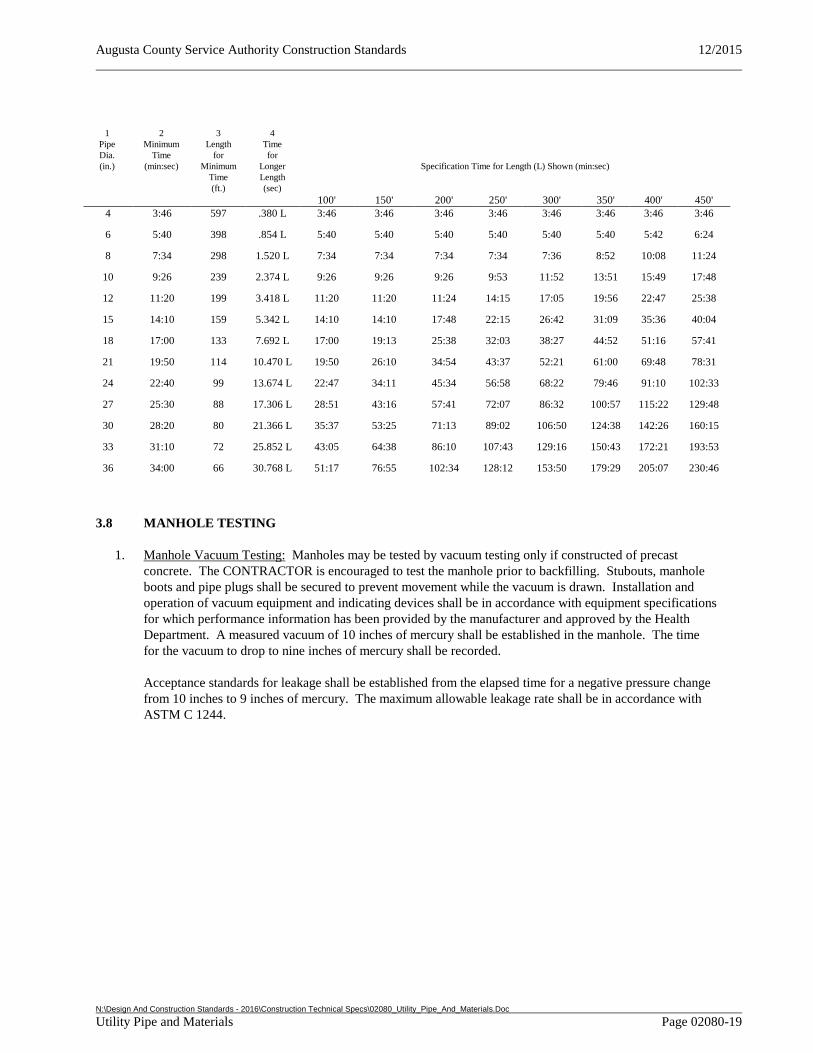
Augusta County Service Authority Construction Standards 12/2015
N:\Design And Construction Standards - 2016\Construction Technical Specs\02080_Utility_Pipe_And_Materials.Doc Utility Pipe and Materials Page 02080-19
1 Pipe Dia. (in.)
2 Minimum
Time (min:sec)
3 Length
for Minimum
Time (ft.)
4 Time for
Longer Length (sec)
Specification Time for Length (L) Shown (min:sec)
100' 150' 200' 250' 300' 350' 400' 450' 4 3:46 597 .380 L 3:46 3:46 3:46 3:46 3:46 3:46 3:46 3:46
6 5:40 398 .854 L 5:40 5:40 5:40 5:40 5:40 5:40 5:42 6:24
8 7:34 298 1.520 L 7:34 7:34 7:34 7:34 7:36 8:52 10:08 11:24
10 9:26 239 2.374 L 9:26 9:26 9:26 9:53 11:52 13:51 15:49 17:48
12 11:20 199 3.418 L 11:20 11:20 11:24 14:15 17:05 19:56 22:47 25:38
15 14:10 159 5.342 L 14:10 14:10 17:48 22:15 26:42 31:09 35:36 40:04
18 17:00 133 7.692 L 17:00 19:13 25:38 32:03 38:27 44:52 51:16 57:41
21 19:50 114 10.470 L 19:50 26:10 34:54 43:37 52:21 61:00 69:48 78:31
24 22:40 99 13.674 L 22:47 34:11 45:34 56:58 68:22 79:46 91:10 102:33
27 25:30 88 17.306 L 28:51 43:16 57:41 72:07 86:32 100:57 115:22 129:48
30 28:20 80 21.366 L 35:37 53:25 71:13 89:02 106:50 124:38 142:26 160:15
33 31:10 72 25.852 L 43:05 64:38 86:10 107:43 129:16 150:43 172:21 193:53
36 34:00 66 30.768 L 51:17 76:55 102:34 128:12 153:50 179:29 205:07 230:46
3.8 MANHOLE TESTING
1. Manhole Vacuum Testing: Manholes may be tested by vacuum testing only if constructed of precast concrete. The CONTRACTOR is encouraged to test the manhole prior to backfilling. Stubouts, manhole boots and pipe plugs shall be secured to prevent movement while the vacuum is drawn. Installation and operation of vacuum equipment and indicating devices shall be in accordance with equipment specifications for which performance information has been provided by the manufacturer and approved by the Health Department. A measured vacuum of 10 inches of mercury shall be established in the manhole. The time for the vacuum to drop to nine inches of mercury shall be recorded.
Acceptance standards for leakage shall be established from the elapsed time for a negative pressure change from 10 inches to 9 inches of mercury. The maximum allowable leakage rate shall be in accordance with ASTM C 1244.
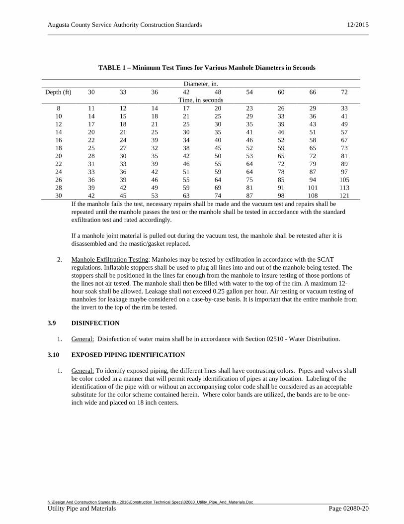
Augusta County Service Authority Construction Standards 12/2015
N:\Design And Construction Standards - 2016\Construction Technical Specs\02080_Utility_Pipe_And_Materials.Doc Utility Pipe and Materials Page 02080-20
TABLE 1 – Minimum Test Times for Various Manhole Diameters in Seconds
Diameter, in. Depth (ft) 30 33 36 42 48 54 60 66 72
Time, in seconds 8 11 12 14 17 20 23 26 29 33
10 14 15 18 21 25 29 33 36 41 12 17 18 21 25 30 35 39 43 49 14 20 21 25 30 35 41 46 51 57 16 22 24 39 34 40 46 52 58 67 18 25 27 32 38 45 52 59 65 73 20 28 30 35 42 50 53 65 72 81 22 31 33 39 46 55 64 72 79 89 24 33 36 42 51 59 64 78 87 97 26 36 39 46 55 64 75 85 94 105 28 39 42 49 59 69 81 91 101 113 30 42 45 53 63 74 87 98 108 121 If the manhole fails the test, necessary repairs shall be made and the vacuum test and repairs shall be
repeated until the manhole passes the test or the manhole shall be tested in accordance with the standard exfiltration test and rated accordingly.
If a manhole joint material is pulled out during the vacuum test, the manhole shall be retested after it is disassembled and the mastic/gasket replaced.
2. Manhole Exfiltration Testing: Manholes may be tested by exfiltration in accordance with the SCAT regulations. Inflatable stoppers shall be used to plug all lines into and out of the manhole being tested. The stoppers shall be positioned in the lines far enough from the manhole to insure testing of those portions of the lines not air tested. The manhole shall then be filled with water to the top of the rim. A maximum 12-hour soak shall be allowed. Leakage shall not exceed 0.25 gallon per hour. Air testing or vacuum testing of manholes for leakage maybe considered on a case-by-case basis. It is important that the entire manhole from the invert to the top of the rim be tested.
3.9 DISINFECTION
1. General: Disinfection of water mains shall be in accordance with Section 02510 - Water Distribution.
3.10 EXPOSED PIPING IDENTIFICATION
1. General: To identify exposed piping, the different lines shall have contrasting colors. Pipes and valves shall be color coded in a manner that will permit ready identification of pipes at any location. Labeling of the identification of the pipe with or without an accompanying color code shall be considered as an acceptable substitute for the color scheme contained herein. Where color bands are utilized, the bands are to be one-inch wide and placed on 18 inch centers.
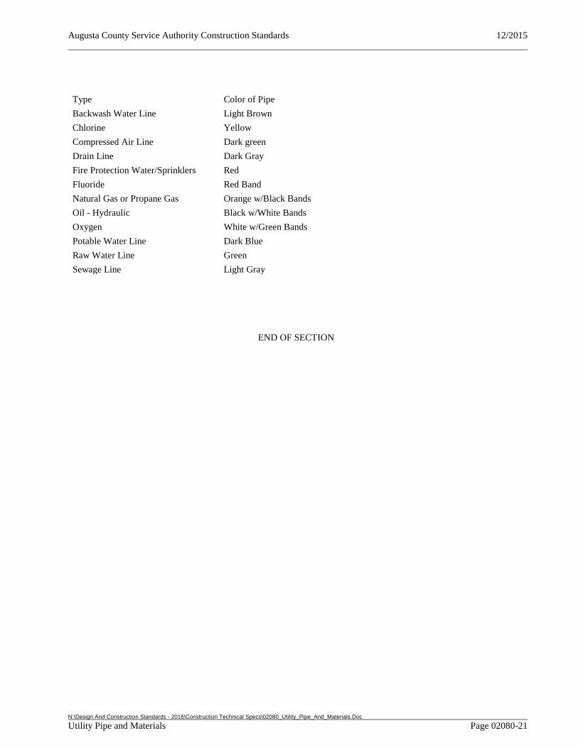
Augusta County Service Authority Construction Standards 12/2015
N:\Design And Construction Standards - 2016\Construction Technical Specs\02080_Utility_Pipe_And_Materials.Doc Utility Pipe and Materials Page 02080-21
Type Color of Pipe
Backwash Water Line Light Brown
Chlorine Yellow
Compressed Air Line Dark green
Drain Line Dark Gray
Fire Protection Water/Sprinklers Red
Fluoride Red Band
Natural Gas or Propane Gas Orange w/Black Bands
Oil - Hydraulic Black w/White Bands
Oxygen White w/Green Bands
Potable Water Line Dark Blue
Raw Water Line Green
Sewage Line Light Gray
END OF SECTION
Augusta County Service Authority Construction Standards 12/2015
N:\Design And Construction Standards - 2016\Construction Technical Specs\02085_Valves_And_Cocks.Doc Valves and Cocks Page 02085-1
SECTION 02085 - VALVES AND COCKS
PART 1 GENERAL
1.1 REFERENCES
1. General: The work shall comply with the most recent standards or tentative standards as published at the date of the contract and as listed in this specification using the abbreviation shown.
2. Related Sections: Additional Sections of the Documents which are referenced in this Section include:
1) Section 02080 - Utility Pipe and Materials
3. American National Standard Institute (ANSI)/American Society of Sanitary Engineers (ASSE):
1) 1011 Hose Connection Vacuum Breakers
2) 1015 Double Check Backflow Prevention Assemblies
4. American National Standard Institute (ANSI)/American Water Work Association (AWWA):
1) C 504 Standard for Rubber Seated Butterfly Valves
2) C 508 Standard for Swing-Check Valves for Waterworks Service, 2 in (50mm) Through 24 in (600 mm) NPS (Includes addendum C 508a-93)
3) C 515 Standard for Resilient-Seated Gate Valves for Water Supply Service
4) C 512 Air Release, Air/Vacuum, and Combination Air Valves for Waterworks Service
5) C 510 Double Check Valve Backflow Prevention Assembly
6) C511 Reduced-Pressure Principle Backflow Prevention Assembly 7) C530 Pilot-Operated Control Valves
8) C 550 Protective Interior Coatings for Valves and Hydrants
9) C 800 Standard for Underground Service Line Valves and Fittings
5. American Society for Testing and Material (ASTM):
1) A 126 Standard Specification for Gray Iron Castings for Valves, Flanges, and Pipe Fittings
1.2 SYSTEM DESCRIPTION
1. General: Valves shall be non-rising stem, with handwheel, lever, nut, or hydraulic operator, as shown on the plans and specified herein.
Augusta County Service Authority Construction Standards 12/2015
N:\Design And Construction Standards - 2016\Construction Technical Specs\02085_Valves_And_Cocks.Doc Valves and Cocks Page 02085-2
1.3 DELIVERY, STORAGE AND HANDLING
1. Delivery: Deliver valves to the job site packaged, tagged, and marked.
2. Storage: Store valves at the job site off the ground and in accordance with the manufacturers recommendations and in a manner to prevent damage and accumulation of dirt and rust.
PART 2 PRODUCTS
2.1 GATE VALVES
1. Gate Valves: Valves shall be ductile iron, resilient wedge conforming to ANSI/AWWA C 515. Wedge disc shall have two seating surfaces and provide smooth unobstructed waterway with 100 percent smooth passage. The valve shall be designed so that no sliding or shear on the resilient seating surface is present when compressed to a drip tight shut off. Working pressure shall be at least 200 psi for valves 12 inches in diameter and smaller. Valves shall have O-ring seals and open left (counterclockwise) with a 2 inch square wrench nut. Handwheel operators shall be provided for all interior installation. Valves shall have a permanent designation of the direction of opening on the valve. Valve ends shall be of mechanical joint type unless otherwise shown on the plans and specifically approved. Valve shall have fusion bonded epoxy coating inside and out. The valve shall be permanently lubricated. The valve shall have a manganese bronze stem and nut with anti-thrust washers.
2. Tapping Sleeve and Tapping Valve: Complete assembly shall include, tapping sleeve, tapping valve, and bolts and nuts. The sleeve assembly shall be stainless steel.
2.2 CHECK VALVES
1. Check Valves (Liquid): Liquid check valves shall be of the swing check type, bronze mounted with cast iron body conforming to ANSI/AWWA C 508. Valve shall be operated by an external lever and adjustable weight. Disc shall provide a positive seal in the closed position and pivot to provide an unobstructed flow way in the open position.
2. Backflow Preventer: Backflow preventer for installation on fire service line shall be a double check detector assembly. Main valve body shall be in accordance with AWWA C 550. Unit shall conform to ASSE 1015, ANSI/AWWA C 510, UL, FM, and USC and shall be in accordance with the ACSA Cross Connection Control Program. Depending on risk conditions a reduced-pressure principle backflow prevention assembly may be required. Reduced-pressure assemblies shall conform to AWWA C 511.
2.3 BUTTERFLY VALVES
1. Butterfly Valves (Water): Butterfly valves shall be rubber seated, short body in accordance with AWWA C 504, Class 250 ductile iron bodies conforming to AWWA A 536 (unless otherwise specifically approved), bronze discs, 416 stainless steel stems, #12 Buna-N or Ethylene-Propylene seat and steam O-rings, and with hand-wheel actuator with position indicator.
2.4 PLUG VALVES
1. Plug Valves: Valves shall be ductile or cast iron provided with standard mechanical joint or flange ends as shown on the plans and shall be ANSI rated at 150 psi. Valve shall be capable of bubble tight closure but adjustable to stop positions partially closed for throttling. Underground valves shall be fitted with a standard 2 inch operating nut. Exposed valves shall be provided with a handwheel or lever handle for operation. Valve liners and seats shall be of a material suitable for use with an abrasive sanitary sludge.
Augusta County Service Authority Construction Standards 12/2015
N:\Design And Construction Standards - 2016\Construction Technical Specs\02085_Valves_And_Cocks.Doc Valves and Cocks Page 02085-3
2.5 PVC BALL VALVES
1. General: Valves shall be manufactured of PVC Type 1 Grade 1 with EPDM O-ring seals, true union connections, and threaded end connectors. Valves shall be listed by NSF International Standard 61.
2.6 CONTROL VALVES
1. Pressure Control and Altitude (Water Level) Control Valves (AWWA C 530): Altitude valve(s) shall be one way flow, automatic control valve used to shut off incoming flow in a reservoir at a field adjustable water level without the use of floats or other external control devices. Valve shall be of the center guided diaphragm actuated globe, or angle valve type, flanged end, capable of being serviced without removal from the piping. All control valve body and cover materials shall be ductile iron conforming to AWWA A536. Valve stem shall be stainless steel and diaphragms shall be of reinforced synthetic rubber. Valve shall be non-throttling. The control pilot shall be a direct acting, adjustable, spring loaded diaphragm actuated valve of corrosion resistant construction. Valve shall be rated for working pressures meeting system requirements as determined by the design engineer.
2.7 AIR RELEASE VALVES
1. Air Release, Air Vacuum, and Combination Valves for Water: Air release valve shall be cast or ductile iron (ANSI/AWWA C 512), stainless steel (ASTM A744 CF8M) or reinforced nylon body with a stainless steel or polypropylene float in accordance with the Approved Products List. Orifice shall be sized as shown on the plans. Air release valve shall be installed in accordance with the Standard Detail.
2. Air Release, Air Vacuum, and Combination Valves for Sewer: Air release valves shall be cast iron meeting requirement of ASTM A126 Class B, stainless steel (ASTM A744 CF8M) or reinforced nylon body. Orifice shall be sized as shown on the plans to include a screened inlet.
2.9 MISCELLANEOUS VALVES
1. Corporation Stop: Unit shall have inlet threads conforming to ANSI/AWWA C 800, commonly known as the “Mueller” thread, and an outlet compatible with the service pipe. Size shall be determined based on the application and approved by the Authority.
2. Hose Bibb: Assembly shall be anti-contamination wall faucet. Valve shall be furnished with approved vacuum breaker which complies with ANSI/ASSE 1011 and has 3/4 inch male hose threads. Valve shall be of brass construction with adjustable packing nut and deep stem guard, Teflon impregnated packing and standard "O" size washer and wheel handle. Inlet shall be 1/2 inch copper tube.
3. Sampling Taps: The sampling tap shall be plain end spigot faucet, renewable seats, tee handles, polished chrome plated as shown on the Approved Products List.
4. Frost Proof Spigot: The frost proof spigot shall meet ASSE 1057 Sanitary Yard Hydrant Standard, shall include a backflow preventer, and shall be of the type listed in the Approved Products List.
2.10 RELATED ITEMS
1. Valve Boxes: Boxes shall be furnished and installed for all buried valves. Valve boxes shall be installed directly over valves and centered on the valve nut, and carefully backfilled so that the box is plumb, level and flush with the finish grade or pavement. The valve boxes shall be a 2-piece sliding type, 24”-36” variable height with 5 ¼ inch shaft in accordance with the Standard Detail. The word “water” shall be cast on the box lid in letters not less than 1 inch high for all water valves. Heavy duty (H20 Rated), domestic made with a counterweighted lid shall be provided in traffic areas. Locking lid types shall be provided upon request.
Augusta County Service Authority Construction Standards 12/2015
N:\Design And Construction Standards - 2016\Construction Technical Specs\02085_Valves_And_Cocks.Doc Valves and Cocks Page 02085-4
PART 3 EXECUTION
3.1 INSTALLATION - ALL VALVES
1. General: Valve installation shall comply with the Standard Details and the Manufacturer's recommendations.
2. Stems: Shall be oriented for accessibility as approved by the Authority's Representative. Do not install valves with stems in the downward direction.
3. Setting of Valves: A valve box shall be provided for every valve. The valve box shall not transmit shock or stress to the valve and shall be centered and plumb over the wrench nut of the valve, with the box cover flush with the surface of the finished grade or as directed by the Authority’s Representative. Valves boxes shall be installed in accordance with the Standard Detail.
4. Transmitting Forces: Valves and valve boxes shall be installed so no forces are transmitted to the valve through the piping or valve boxes. All valves shall be restrained. Concrete blocks shall be provided underneath all valves 12” or greater in accordance with the Standard Detail.
5. Cleaning: All valves and appurtenances shall be flushed clear of all foreign material after installation.
7. Testing: Field test all valves and appurtenances for proper operation, proper adjustments and settings, freedom from vibration, binding, scrapings, and other defects. Check all valve supports for strength and high quality workmanship. All defects shall be corrected to the satisfaction of the Authority’s Representative. Hydrostatic and leakage tests shall be in accordance with Section 02080 - Utility Pipe and Materials.
END OF SECTION
Augusta County Service Authority Construction Standards 12/2015
N:\Design And Construction Standards - 2016\Construction Technical Specs\02200_Site_Construction_For_Pump_Stations.Doc Site Construction for Pump Stations Page 02200-1
SECTION 02200 - SITE CONSTRUCTION FOR PUMP STATIONS
PART 1 GENERAL
1.1 REFERENCES
1. General: The work shall comply with the most recent standards or tentative standards as published at the date of the contract and as listed in this specification using the abbreviation shown.
2. Related Sections: Additional Sections of the Documents which are referenced in this Section Include:
a. Section 03400 – Precast and Cast-in-Place Concrete
b. Section 02317 – Grading, Excavation, Trenching, & Backfilling
3. American National Standards Institute (ANSI)/American Concrete Institute (ACI):
1) 301 Specifications for Structural Concrete
2) 303R Guide to Cast-in-Place Architectural Concrete Practice
3) 304.2R Placing Concrete by Pumping Methods
4) 306R Standard Specification for Cold Weather Concreting
5) 315 Details and Detailing of Concrete Reinforcement
6) 318 Building Code Requirements for Structural Concrete (ACI 318-99) and Commentary (ACI 318R-99)
7) 350R Environmental Engineering Concrete Structures
4. Virginia Department of Transportation Road and Bridge Specifications (VDOT):
1) 208 Subbase and Aggregate Base Material
2) 211 Asphalt Concrete
3) 305 Subgrade and Shoulders
4) 308 Subbase Course
5) 309 Aggregate Base Course
6) 310 Tack Coat
7) 311 Prime Coat
8) 312 Seal Coat
9) 314 Penetration Surface Courses
10) 315 Asphalt Concrete Pavement
Augusta County Service Authority Construction Standards 12/2015
N:\Design And Construction Standards - 2016\Construction Technical Specs\02200_Site_Construction_For_Pump_Stations.Doc Site Construction for Pump Stations Page 02200-2
5. American Society for Testing and Materials (ASTM):
1) A 185 Standard Specification for Steel Welded Wire Fabric, Plain, for Concrete
2) A 615 Standard Specification for Deformed and Plain Billet-Steel Bars for Concrete Reinforcement
3) C 29 Standard Test Method for Bulk Density (“Unit Weight”) and Voids in Aggregate
4) C 33 Specification for Concrete Aggregates
5) C 94 Standard Specification for Ready-Mixed Concrete
6) C 150 Standard Specification for Portland Cement
7) D 1751 Standard Specification for Preformed Expansion Joint Filler for Concrete Paving and Structural Construction (Nonextruding and Resilient Bituminous Types)
6. Concrete Reinforcing Steel Institute (CRSI):
1) Manual of Standard Practices
1.2 QUALITY ASSURANCE
1. Asphalt: The VDOT Standards and Specifications shall define temperature restrictions, application procedures, mix components, and material references. All materials and application procedures shall be in accordance with VDOT Standards and Specifications.
2. Cast-in Place Concrete: Cast-in-place concrete shall comply with the Building Code Requirements for Structural Concrete (ANSI/ACI 318) and all applicable requirements of the Specifications for Structural Concrete (ANSI/ACI 301).
3. Precast Concrete: Precast concrete shall comply with ASTM C587, ASTM C858, ASTM C891, and ASTM C1037.
4. Testing: The Geotechnical Engineer shall observe the following to determine if the work has been performed in accordance with these specifications:
1) Subgrade prior to placing base stone.
2) Base stone prior to laying asphalt.
3) Surface course application.
It is the Contractor’s responsibility to coordinate inspections with the Geotechnical Engineer and the Authority’s Representative.
Augusta County Service Authority Construction Standards 12/2015
N:\Design And Construction Standards - 2016\Construction Technical Specs\02200_Site_Construction_For_Pump_Stations.Doc Site Construction for Pump Stations Page 02200-3
1.3 SUBMITTALS
1. Concrete Mix Designs:
1) Prior to proceeding with any concrete work, secure concrete mix designs from the concrete supplier, and submit to the Authority’s Representative for review and approval. Depending on application, mix design may require the builder/developer to submit the mix design that has been prepared/approved by an engineer licensed in the Commonwealth of Virginia.
2) Distribute approved mix designs to testing laboratory, batch plant, job site, and governmental agencies having jurisdiction.
1.4 MAINTENANCE
1. Streets: The CONTRACTOR shall maintain and repair existing streets and drivewaysas necessary during the construction period and provide for additional applications of compacted stone in accordance with the plans after completion of trenching and prior to paving, as required.
1.5 DEFINITIONS
1. Clearing: Clearing shall consist of the satisfactory disposal of the trees and other vegetation designated for removal, including down timber, snags, brush, and rubbish occurring in the areas to be cleared.
2. Grubbing: Grubbing shall consist of the removal and disposal of brush, stumps, roots larger than 1 inch in diameter, and matted roots from the designated grubbing areas.
1.6 EROSION AND SEDIMENT CONTROL
1. General: Erosion and Sediment control is the sole responsibility of the Contractor/Developer. No site requiring additional Erosion and Sediment Control work will be accepted by the Authority.
PART 2 PRODUCTS
2.1 ACCESS ROAD AND PARKING
1. General: Gravel roads, access drives, parking areas, or other gravel surfaces shall consist of a minimum of 6 inches of compacted VDOT #21A aggregate unless shown otherwise on the plans.
2. Subgrade: Subgrade shall conform to VDOT Specification 305.
3. Asphalt: Asphalt, where required by the plans, shall comply with details as shown on the approved plans and applicable VDOT Specifications. Joints in/with existing pavement shall be overlapped and sealed.
4. Asphalt Drive and Parking Areas:
1) Aggregate base course shall consist of VDOT #21A aggregate base material and shall conform to VDOT Specification 208.
2) Prime coat shall consist of liquid asphalt material meeting the requirements of VDOT Specification 311.
3) Bituminous concrete base course shall consist of bituminous concrete base material designed to handle the intended traffic loading and conform to VDOT Specification 315.
Augusta County Service Authority Construction Standards 12/2015
N:\Design And Construction Standards - 2016\Construction Technical Specs\02200_Site_Construction_For_Pump_Stations.Doc Site Construction for Pump Stations Page 02200-4
5. Asphalt Surface Course and Pavement Overlay:
1) Tack coat shall consist of liquid asphalt material meeting the requirements of VDOT Specification 310.
2) Bituminous concrete surface course or overlay shall consist of bituminous concrete surface material designed to handle the intended traffic loading and shall conform to VDOT Specification 211.
6. Asphalt Paving Limitations:
1) Apply prime and tack coats when ambient temperature is above 50 degrees F (10 degrees C) and when temperature has not been below 35 degrees F (1 degree C) for 12 hours immediately prior to application. Do not apply when base is wet or contains an excess of moisture.
2) Construct asphalt concrete base and surface course only when atmospheric temperature is above 40 degrees F (4 degrees C) and when base is dry. Aggregate base course may be placed when air temperature is above 30 degrees F.
2.2 CONCRETE
1. General: Concrete work shall conform to all requirements of ACI 301 and ACI 350R, except as modified by supplemental requirements below.
2. Strength: Concrete shall have a minimum allowable compressive strength specified at 28 days (ACI 301, 3.2). Concrete shall reach a minimum of 80 percent of this design strength before weight supporting forms may be removed (ACI 301, 4.5.5). Earlier removal of non load bearing forms shall be permitted only if approved by the Authority’s Representative.
3. Materials and Testing: Contractor shall comply with the mix design and test requirements as provided by a licensed engineer in the Commonwealth of Virginia.
4. Reinforcement
1) General: Reinforcement materials and installation shall conform to the applicable sections of the latest version or revision of ACI 301, except as modified by the the engineer of record.
2) Strength: Reinforcement shall be of the size shown on the plans with all bars being billet steel, ASTM A 615, Grade 60 unless noted otherwise. Welded wire fabric gauge and mesh size shall be as shown on the plans.
3) Quality Assurance: Comply with the following as minimums:
1) Bars: ASTM A 615, grade 60 unless otherwise shown on the plans using deformed bars for number 3 and larger.
2) Welded wire fabric: ASTM A 185.
3) Bending of rebar shall be in accordance with ACI 318.
4) Supports for reinforcement: Supports for reinforcing bars and welded wire fabric shall comply with CRSI recommendations, including bolsters, chairs and spacers. Wire bar supports shall be rust protected in accordance with CRSI Class 2. Under no circumstances will rebar or other metal pins driven into the ground to support reinforcing steel be allowed.
Augusta County Service Authority Construction Standards 12/2015
N:\Design And Construction Standards - 2016\Construction Technical Specs\02200_Site_Construction_For_Pump_Stations.Doc Site Construction for Pump Stations Page 02200-5
5) Fabricate reinforcement to the required shapes and dimensions, within fabrication tolerances stated in the CRSI "Manual of Standard Practices" and ACI 315.
6) Reinforcement: Do not use reinforcement having any of the following defects:
a) Bar lengths, depths, or bends exceeding the specified fabricating tolerances.
b) Bends or kinks not indicated on the plans or required for this work.
c) Bars with cross-section reduced due to excessive rust or other causes.
7) Contractor shall fabricate reinforcement to the required shapes and dimensions, within fabrication tolerances stated in the CRSI “Manual of Standard Practices”.
5. Waterstops: Waterstops shall be of sufficient size to insure proper anchorage into both adjacent pours. Material shall be as shown on the plans.
6. Joint Filler: Joint filler shall be a premolded expansion joint filler complying with ASTM D 1751.
7. Pipe Sleeves: Pipe sleeves shall be ductile iron or pressure rated PVC in accordance with Section 02080 - Utility Pipe and Materials. Sleeves shall be two piece for assembly around existing pipes or sleeves may be cut and reassembled around existing pipes. Sleeve size shall be adequate to install sleeve seal.
8. Sleeve Seals: Sleeve to pipe seals shall be synthetic rubber compression type seals similar to Link-Seal.
9. Portland Cement Concrete Limitations:
1) All concrete work shall be protected from damage or reduced strength which could be caused by precipitation, freezing action, or low temperatures. All work with concrete when air temperature is below 40 degrees F shall comply with Standard Specification for Cold Weather Concreting ANSI/ACI 306R and as specified herein.
2) Do not use antifreeze agents or chemical accelerators, unless written approval for such use has been given by the engineer of record and/or Authority Representative.
3) Do not use aggregates that contain ice or snow. Do not place concrete on frozen soils or subgrade.
4) If air temperatures have fallen below 40 degrees F, or are expected to fall below 40 degrees F within twenty-four hours, heat water and all aggregates before mixing. Concrete mixture temperature at point of placement shall not be less than 60 degrees F or more than 80 degrees F.
2.3 SEEDING
1. Seeding/finish work shall be in accordance with Section 2317-3.3
PART 3 EXECUTION
3.1 SITE WORK
1. Clearing: An acceptable site shall have all trees, stumps, roots, brush, vegetation, and other waster or debris in areas cleared, except such trees, vegetation, or other existing features indicated on the plans to be protected. Trees and vegetation to be left standing shall be protected from damage incident to clearing, grubbing, and construction operations by the erection of barriers or by such other means as the circumstances require. In the event trees or other features to be protected are damaged, they shall be
Augusta County Service Authority Construction Standards 12/2015
N:\Design And Construction Standards - 2016\Construction Technical Specs\02200_Site_Construction_For_Pump_Stations.Doc Site Construction for Pump Stations Page 02200-6
replaced by the contractor at no cost to the Authority and covered by the warranty and maintenance period. A healthy stand of grass shall be provided on all cleared areas of the site.
2. Grubbing: Material to be grubbed, together with logs and other organic debris not suitable for foundation purposes, shall be removed to a depth of not less than 12 inches below the original ground in areas such as proposed buildings, grassed areas, and areas to be paved. Depressions made by grubbing shall be filled with suitable material and compacted to make the surface conform with the adjacent surfaces.
3. Disposal of Materials: Legal disposal of all debris and unsuitable or surplus material is the sole responsibility of the Contractor. All excess materials must be removed from the site prior to acceptance by the Authority.
4. Drainage: The Contractor/Developer shall be responsible for providing proper stormwater drainage for the site.
5. Erosion and Sediment Control: Erosion and Sediment control measures and stabilization shall be in accordance with the requirements of Augusta County Ordinance and State Requirements. This may include an Erosion and Sediment Control Narrative and a Storm Water Pollution and Prevention Plan.
3.2 ACCESS ROAD AND PARKING SURFACE TREATMENT
1. General. Asphalt concrete pavement construction shall be in accordance with the details on the plans and construction shall be in accordance with VDOT Specification 315.
2. Subgrade: Uniformly smooth grade excavated areas, filled sections, and adjacent transition areas. Subgrade shall be rolled and compacted prior to stone application.
3. Protection: After final rolling, do not permit vehicular traffic on pavement until it has cooled and hardened.
4. Barricades: Erect barricades to protect paving from traffic until mixture has cooled enough not to become marked.
5. Surface Drainage: The surface of all paving work shall slope and drain surface water toward catch basins or swales. If water stands, paving shall be corrected to prevent standing water, subject to the Authority Representative’s approval.
6. Remedial Work: Repair or replace deficient work as directed by the Authority’s Representative at no cost to the Authority.
3.3 CONCRETE
1. General: A subbase of 6 inches of VDOT #57 stone shall be placed under all slabs, unless otherwise indicated on the plans.
2. Reinforcing: Comply with the following, as well as the specified standards, for details and methods of reinforcing placement and supports.
1) Clean reinforcement and remove loose dust and mill scale, earth, and other materials which reduce bond or destroy bond with concrete.
2) Position, support, and secure reinforcement against displacement by forms, construction, and the concrete placement operations.
3) Place reinforcement to obtain the required coverages for concrete protection as specified by ACI 301.
Augusta County Service Authority Construction Standards 12/2015
N:\Design And Construction Standards - 2016\Construction Technical Specs\02200_Site_Construction_For_Pump_Stations.Doc Site Construction for Pump Stations Page 02200-7
4) Install welded wire fabric in as long a length as practicable, lapping adjoining pieces one full mesh minimum.
5) Dowels shall match reinforcement with which they lap unless noted.
6) Unless otherwise shown on the plans, or required by governmental agencies having jurisdiction, or mechanical lap type splices are used, overlap bars per paragraph 2.2.4 (splicing) of this specification. Mechanical lap devices shall be approved by the Authority’s Representative prior to use.
7) Do not field bend reinforcement without written permission of the Authority’s Representative. In no case may bars be heated to facilitate bending.
8) Welding, oxy-acetylene torch cutting, or the application of heat to reinforcing steel, anchor bolts, or any metal object embedded in concrete is strictly forbidden unless approved in writing by the Authority’s Representative.
3. Embedded Items:
1) Do not embed conduit or piping in structural concrete unless specifically approved by the Authority and incorporated into the structural concrete design.
2) Set bolts, post bases, inserts, and other required items in the concrete, accurately secured so they will not be displaced, and in the precise locations needed.
4. Pipe Sleeves: Provide pipe sleeves for all existing and new pipes penetrating the wall. Sleeves shall be installed flush with the outside surfaces of the wall. Pipes shall be sealed within the sleeves by a compression type pipe penetration seal similar to “Link-Seal”.
5. Footing: Footing depth and construction shall be as shown on the plans. Bottoms of all exterior footings shall be adequately drained before foundation concrete is placed.
6. Insulation: Insulation shall be placed at the locations as shown on the plans.
7. Mixing Concrete:
Transit mix concrete shall be in accordance with applicable ACI/ASTM standards.
8. Placing Concrete: Placing concrete shall be in accordance with applicable ACI/ASTM standards.
9. Conveying:
1) Perform concrete placing at such a rate that concrete which is being integrated with fresh concrete is still plastic.
2) Deposit concrete as nearly as practicable in its final location so as to avoid separation due to rehandling and flowing.
3) Do not use concrete which becomes non-plastic and unworkable, does not meet required quality control limits, or has been contaminated by foreign materials.
4) Remove rejected concrete from the job site.
10. Placing Concrete in Forms: Placing concrete in forms shall be in accordance with applicable ACI/ASTM standards.
Augusta County Service Authority Construction Standards 12/2015
N:\Design And Construction Standards - 2016\Construction Technical Specs\02200_Site_Construction_For_Pump_Stations.Doc Site Construction for Pump Stations Page 02200-8
11. Placing Concrete for Walls: Placing concrete for walls shall be in accordance with applicable ACI/ASTM standards.
12. Placing Concrete Slabs:
1) Deposit and consolidate concrete slabs in a continuous operation.
2) Bring slab surfaces to the correct level with a straightedge, and then strike off.
3) Use bullfloats or darbies to smooth the surface, leaving the surface free from bumps and hollows.
4) Do not sprinkle water on the plastic surface. Do not disturb the slab surface prior to start of finishing operations.
13. Cold Weather Placement:
1) All concrete work shall be protected from damage or reduced strength which could be caused by freezing actions or low temperatures. All work with concrete mixture when air temperature is below 40 degrees F shall comply with ACI 306R and as specified herein.
2) Do not use antifreeze agents or chemical accelerators, unless written approval for such use has been given by the Authority’s Representative.
3) Do not use aggregates that contain ice or snow. Do not place concrete over frozen soils or subgrade.
4) If air temperatures have fallen below 40 degrees F, or are expected to fall below 40 degrees F within twenty-four hours, heat water and all aggregates before mixing. Concrete mixture temperature at point of placement shall not be less than 60 degrees F nor more than 80 degrees F.
14. Consolidation:
1) Consolidate each layer of concrete immediately after placing, by use of internal concrete vibrators supplemented by hand spading, rodding, or tamping.
2) Do not vibrate forms or reinforcement.
3) Do not use vibrators to transport concrete inside the forms.
15. Curing: Concrete curing shall be done with accordance with ACI 303R. Cold weather curing shall be in accordance with ACI 306R.
16. Expansion Joints: Expansion joints are to be provided at locations shown on the plans or at other locations during construction as approved by the Authority’s Representative. Joints shall be filled with a premolded expansion joint filler complying with ASTM D 1751.
17. Construction Joints: Construction joints shall be provided as shown on the plans or as preapproved by the Authority’s Representative. Joints shall be kept free of form oil or other materials which may hamper bonding. Soiled surfaces shall be washed, mechanically cleaned or brushed blasted to the satisfaction of the Authority’s Representative. A surface bonding agent shall be applied at all joints in accordance with the manufacturer's recommendation.
1) Do not use construction joints except as shown on the plans.
2) If additional construction joints are found to be required, secure the Authority’s Representative's approval of joint design and location prior to start of concrete placement.
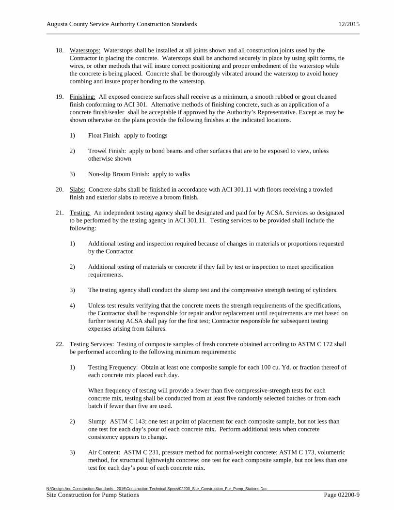
Augusta County Service Authority Construction Standards 12/2015
N:\Design And Construction Standards - 2016\Construction Technical Specs\02200_Site_Construction_For_Pump_Stations.Doc Site Construction for Pump Stations Page 02200-9
18. Waterstops: Waterstops shall be installed at all joints shown and all construction joints used by the Contractor in placing the concrete. Waterstops shall be anchored securely in place by using split forms, tie wires, or other methods that will insure correct positioning and proper embedment of the waterstop while the concrete is being placed. Concrete shall be thoroughly vibrated around the waterstop to avoid honey combing and insure proper bonding to the waterstop.
19. Finishing: All exposed concrete surfaces shall receive as a minimum, a smooth rubbed or grout cleaned finish conforming to ACI 301. Alternative methods of finishing concrete, such as an application of a concrete finish/sealer shall be acceptable if approved by the Authority’s Representative. Except as may be shown otherwise on the plans provide the following finishes at the indicated locations.
1) Float Finish: apply to footings
2) Trowel Finish: apply to bond beams and other surfaces that are to be exposed to view, unless otherwise shown
3) Non-slip Broom Finish: apply to walks
20. Slabs: Concrete slabs shall be finished in accordance with ACI 301.11 with floors receiving a trowled finish and exterior slabs to receive a broom finish.
21. Testing: An independent testing agency shall be designated and paid for by ACSA. Services so designated to be performed by the testing agency in ACI 301.11. Testing services to be provided shall include the following:
1) Additional testing and inspection required because of changes in materials or proportions requested by the Contractor.
2) Additional testing of materials or concrete if they fail by test or inspection to meet specification requirements.
3) The testing agency shall conduct the slump test and the compressive strength testing of cylinders.
4) Unless test results verifying that the concrete meets the strength requirements of the specifications, the Contractor shall be responsible for repair and/or replacement until requirements are met based on further testing ACSA shall pay for the first test; Contractor responsible for subsequent testing expenses arising from failures.
22. Testing Services: Testing of composite samples of fresh concrete obtained according to ASTM C 172 shall be performed according to the following minimum requirements:
1) Testing Frequency: Obtain at least one composite sample for each 100 cu. Yd. or fraction thereof of each concrete mix placed each day.
When frequency of testing will provide a fewer than five compressive-strength tests for each concrete mix, testing shall be conducted from at least five randomly selected batches or from each batch if fewer than five are used.
2) Slump: ASTM C 143; one test at point of placement for each composite sample, but not less than one test for each day’s pour of each concrete mix. Perform additional tests when concrete consistency appears to change.
3) Air Content: ASTM C 231, pressure method for normal-weight concrete; ASTM C 173, volumetric method, for structural lightweight concrete; one test for each composite sample, but not less than one test for each day’s pour of each concrete mix.
Augusta County Service Authority Construction Standards 12/2015
N:\Design And Construction Standards - 2016\Construction Technical Specs\02200_Site_Construction_For_Pump_Stations.Doc Site Construction for Pump Stations Page 02200-10
4) Concrete Temperature: ASTM C 1064; one test hourly when air temperature is 40 deg F and below and when 80 deg F and above, and one test for each composite sample.
5) Compression Test specimens: ASTM C 31/C 31M; cast and laboratory cure one set of four standard cylinder specimens for each composite sample.
6) Compressive-Strength Tests: ASTM C 39; test two laboratory-cured specimens at 7 days and two at 28 days. Test two field-cured specimens at 7 days and two at 28 days. A compressive-strength test shall be the average compressive strength from two specimens obtained from same composite sample and tested at age indicated.
23. Concrete Strength: Strength of each concrete mix will be satisfactory if every average of any three consecutive compressive-strength tests equals or exceeds specified compressive strength and no compressive-strength test value falls below specified compressive strength by more than 500 psi per ACI 301 and ACI 318.
END OF SECTION
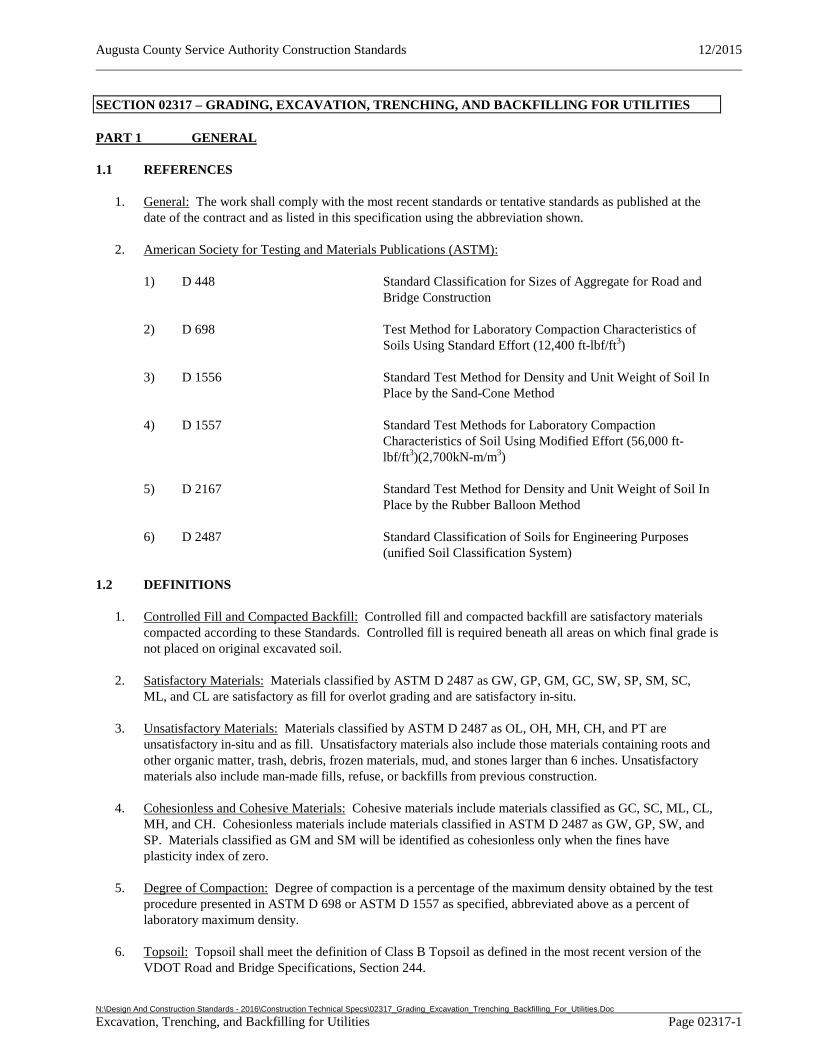
Augusta County Service Authority Construction Standards 12/2015
N:\Design And Construction Standards - 2016\Construction Technical Specs\02317_Grading_Excavation_Trenching_Backfilling_For_Utilities.Doc Excavation, Trenching, and Backfilling for Utilities Page 02317-1
SECTION 02317 – GRADING, EXCAVATION, TRENCHING, AND BACKFILLING FOR UTILITIES
PART 1 GENERAL
1.1 REFERENCES
1. General: The work shall comply with the most recent standards or tentative standards as published at the date of the contract and as listed in this specification using the abbreviation shown.
2. American Society for Testing and Materials Publications (ASTM):
1) D 448 Standard Classification for Sizes of Aggregate for Road and Bridge Construction
2) D 698 Test Method for Laboratory Compaction Characteristics of Soils Using Standard Effort (12,400 ft-lbf/ft3)
3) D 1556 Standard Test Method for Density and Unit Weight of Soil In Place by the Sand-Cone Method
4) D 1557 Standard Test Methods for Laboratory Compaction Characteristics of Soil Using Modified Effort (56,000 ft- lbf/ft3)(2,700kN-m/m3)
5) D 2167 Standard Test Method for Density and Unit Weight of Soil In Place by the Rubber Balloon Method
6) D 2487 Standard Classification of Soils for Engineering Purposes (unified Soil Classification System)
1.2 DEFINITIONS
1. Controlled Fill and Compacted Backfill: Controlled fill and compacted backfill are satisfactory materials compacted according to these Standards. Controlled fill is required beneath all areas on which final grade is not placed on original excavated soil.
2. Satisfactory Materials: Materials classified by ASTM D 2487 as GW, GP, GM, GC, SW, SP, SM, SC, ML, and CL are satisfactory as fill for overlot grading and are satisfactory in-situ.
3. Unsatisfactory Materials: Materials classified by ASTM D 2487 as OL, OH, MH, CH, and PT are unsatisfactory in-situ and as fill. Unsatisfactory materials also include those materials containing roots and other organic matter, trash, debris, frozen materials, mud, and stones larger than 6 inches. Unsatisfactory materials also include man-made fills, refuse, or backfills from previous construction.
4. Cohesionless and Cohesive Materials: Cohesive materials include materials classified as GC, SC, ML, CL, MH, and CH. Cohesionless materials include materials classified in ASTM D 2487 as GW, GP, SW, and SP. Materials classified as GM and SM will be identified as cohesionless only when the fines have plasticity index of zero.
5. Degree of Compaction: Degree of compaction is a percentage of the maximum density obtained by the test procedure presented in ASTM D 698 or ASTM D 1557 as specified, abbreviated above as a percent of laboratory maximum density.
6. Topsoil: Topsoil shall meet the definition of Class B Topsoil as defined in the most recent version of the VDOT Road and Bridge Specifications, Section 244.
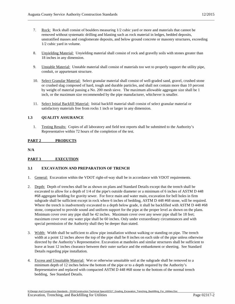
Augusta County Service Authority Construction Standards 12/2015
N:\Design And Construction Standards - 2016\Construction Technical Specs\02317_Grading_Excavation_Trenching_Backfilling_For_Utilities.Doc Excavation, Trenching, and Backfilling for Utilities Page 02317-2
7. Rock: Rock shall consist of boulders measuring 1/2 cubic yard or more and materials that cannot be removed without systematic drilling and blasting such as rock material in ledges, bedded deposits, unstratified masses and conglomerate deposits, and below ground concrete or masonry structures, exceeding 1/2 cubic yard in volume.
8. Unyielding Material: Unyielding material shall consist of rock and gravelly soils with stones greater than 18 inches in any dimension.
9. Unstable Material: Unstable material shall consist of materials too wet to properly support the utility pipe, conduit, or appurtenant structure.
10. Select Granular Material: Select granular material shall consist of well-graded sand, gravel, crushed stone or crushed slag composed of hard, tough and durable particles, and shall not contain more than 10 percent by weight of material passing a No. 200 mesh sieve. The maximum allowable aggregate size shall be 1 inch, or the maximum size recommended by the pipe manufacturer, whichever is smaller.
11. Select Initial Backfill Material: Initial backfill material shall consist of select granular material or satisfactory materials free from rocks 1 inch or larger in any dimension.
1.3 QUALITY ASSURANCE
1. Testing Results: Copies of all laboratory and field test reports shall be submitted to the Authority’s Representative within 72 hours of the completion of the test.
PART 2 PRODUCTS
N/A
PART 3 EXECUTION
3.1 EXCAVATION AND PREPARATION OF TRENCH
1. General: Excavation within the VDOT right-of-way shall be in accordance with VDOT requirements.
2. Depth: Depth of trenches shall be as shown on plans and Standard Details except that the trench shall be excavated to allow for a depth of 1/4 of the pipe's outside diameter or a minimum of 6 inches of ASTM D 448 #68 aggregate bedding for gravity sewer. For force main and water main, excavation for bell holes in firm subgrade shall be sufficient except in rock where 6 inches of bedding, ASTM D 448 #68 stone, will be required. Where the trench is inadvertently excavated to a depth below grade, it shall be backfilled with ASTM D 448 #68 stone, compacted to provide sound and uniform support for the pipe at the proper level as shown on the plans. Minimum cover over any pipe shall be 42 inches. Maximum cover over any sewer pipe shall be 18 feet; maximum cover over any water pipe shall be 60 inches. Only under extraordinary circumstances and with special permission of the Authority shall they be deeper than stated.
3. Width: Width shall be sufficient to allow pipe installation without walking or standing on pipe. The trench width at a point 12 inches above the top of the pipe shall be 8 inches on each side of the pipe unless otherwise directed by the Authority’s Representative. Excavation at manholes and similar structures shall be sufficient to leave at least 12 inches clearance between their outer surface and the embankment or sheeting. See Standard Details regarding pipe installation.
4. Excess and Unsuitable Material: Wet or otherwise unsuitable soil at the subgrade shall be removed to a minimum depth of 12 inches below the bottom of the pipe or to a depth required by the Authority’s Representative and replaced with compacted ASTM D 448 #68 stone to the bottom of the normal trench bedding, See Standard Details.
Augusta County Service Authority Construction Standards 12/2015
N:\Design And Construction Standards - 2016\Construction Technical Specs\02317_Grading_Excavation_Trenching_Backfilling_For_Utilities.Doc Excavation, Trenching, and Backfilling for Utilities Page 02317-3
When the bottom of the trench or subgrade is found to consist of material that is unstable to such a degree that it cannot be removed, the Developer’s Engineer shall submit plans to the Authority’s Engineer for review showing the proposed foundation for the pipe and/or appurtenances, using concrete or other material. Concrete encasement may be required where the amount of cover material would be two feet in depth (or less) over the top of the pipe.
5. Rock Excavation: Ledge rock, boulders, and large stones shall be removed to provide a clearance of at least 6 inches below and on each side of all pipe, manholes, valves or other appurtenances and over-depth shall be backfilled with satisfactory material and compacted in conformance with BACKFILLING subsection. These clearances shall also be observed for pieces of concrete or masonry and other debris or subterranean structures, such as masonry walls, piers, or foundations that may be encountered during excavation. See Standard Details.
6. Trench Protection: Protection shall be the sole responsibility of the Contractor.
7. Pumping, Bailing, and Draining: The Contractor shall remove any water without damage to work or property which may accumulate or be found in the trenches or other excavations and shall keep the excavations clear of water while work is being installed, unless approval to the contrary is granted by the Authority’s Representative.
8. Blasting: Blasting shall be in accordance with State and local ordinances and shall be the sole responsibility of the Contractor.
9. Pavement and Concrete Removal: Shall use clean, straight lines, remove to joint, and other standard practices to remove and replace material to an equal to or better than preconstruction condition. At the location of the joint, there shall be a smooth transition to the existing pavement or concrete.
3.2 BACKFILLING
1. Materials: All backfill materials shall be free from mud, refuse, construction debris, organic material, boulders, frozen or otherwise unsuitable material. Select initial backfill shall be as defined in Part 1 of this section. Remaining backfill may contain stones up to 6 inches in their greatest dimension, unless otherwise specified. The Contractor may backfill with the excavated material, provided it meets the conditions as stated above.
2. Gravity Sewer Bedding: Bedding shall be required on all gravity sewer lines, and shall be in accordance with Standard Details. Bedding material shall extend from the excavated trench bottom to the pipe springline (midpoint) except on PVC pipe where it shall extend to 6 inches above the top of the pipe. Bedding material shall be compacted to 95 percent of maximum density as measured by ASTM D 698.
3. Pressure Pipe Bedding: Bedding for pressure pipe shall consist of firm subgrade with excavation for bell holes. When trench is in rock or non-select material bedding shall consist of a gravel base, unless shown otherwise on plans, and shall be in accordance with Standard Details. Gravel bedding material shall extend from the excavated trench bottom to the pipe spring-line (midpoint). Bedding material shall be compacted to 95 percent of maximum density as measured by ASTM D 698.
4. Backfilling to Grade: Initial backfill shall be with select material to a depth of at least two feet over the pipe and compacted prior to placement of remaining backfill. Initial backfill shall be placed in lifts not to exceed 6 inches (prior to compaction). Remaining backfilling shall be carried up evenly in lifts not to exceed 2 feet.
5. Backfilling in Controlled Areas: Backfill under pavement, proposed pavement, or in areas within rights-of-way shall be in layers of selected earth not more than 6 inches in thickness, and each layer shall be compacted to a minimum of 95 percent of maximum density at optimum moisture when tested in accordance with ASTM D 698. Compaction shall be in accordance with instructions in this Section as modified herein. The top course of backfill directly under pavement shall consist of aggregate base material meeting the requirements of VDOT #21A stone. The depth of this course shall be at least 1-l/2 times

Augusta County Service Authority Construction Standards 12/2015
N:\Design And Construction Standards - 2016\Construction Technical Specs\02317_Grading_Excavation_Trenching_Backfilling_For_Utilities.Doc Excavation, Trenching, and Backfilling for Utilities Page 02317-4
greater than the existing base course, but in no case shall be less than 6 inches. Moisture content shall be within 20 percent of optimum.
6. Backfill Compaction Testing: The Contractor shall demonstrate the adequacy of backfill compaction by performing density testing of the completed trench at no cost to the Authority. Testing shall be performed by an independent testing laboratory qualified to perform such tests and approved by Authority’s Representative. Density testing shall be performed at three depths for each test location: surface, mid-depth, and near maximum trench depth. The character of the backfill material will be observed during the excavation for density testing to determine conformance with the specifications. Density testing shall be performed using nuclear field density equipment or conventional weight-volume methods. If the weight-volume method is used, volume shall be determined by using the sand replacement test (ASTM D 1556) or liquid displacement methods (ASTM D 2167). If nuclear methods are used, the trench correction effect shall be accounted for by recalibrating the nuclear gauge on its calibration block at the location of each test prior to taking the density measurement. The Contractor shall furnish all equipment, tools, and labor to prepare the test site for testing. Testing shall be performed by an independent testing laboratory qualified to perform such tests and approved by the Authority’s Representative. All testing shall be witnessed by the Authority’s Representative. The test shall be repeated until satisfactory results are obtained.
1) Normal Testing Frequency: One test shall be performed within the first 500 feet of pipe installed by each crew. This test will be used as an initial evaluation of the compaction methods being used. Beyond the initial 500 feet, one test shall be performed in each 1,000 foot section of pipe installed or fraction thereof. Testing shall progress as each 1,000 foot section is completed. The location of the test within each section shall be selected by the Authority’s Representative. Testing which indicated that unacceptable material has been incorporated into the backfill, or that insufficient compaction is being obtained shall be followed by expanded testing to determine the limits of the unacceptable backfill.
2) Expanded Testing Requirements: If normal testing within a test section indicated unacceptable backfill, the Authority’s Representative may require additional testing within the same test section to determine the limits of unacceptable backfill. Unacceptable backfill within the limits established by the testing shall be removed and replaced by the Contractor at no cost to the Authority. Additional testing beyond that required may be performed by the Contractor at his expense to further delineate limits of unacceptable backfill.
3) Additional Testing: Testing beyond the normal frequency or expanded testing required which is requested by the Authority’s Representative, and approved by the Authority, shall be at the Authority's expense.
7. Finished Surfaces: Uniformly smooth grading of disturbed areas shall be required after backfill and compaction. Road shoulders shall have a minimum depth of 6 inches of VDOT #25 or #26 crusher run aggregate, compacted to a minimum 95 percent of maximum density as measured by ASTM D 698. Ditches and gutters shall be finished to drain readily. In grass or lawn areas see Section 3.3. Settlement or other damage that occurs prior to acceptance or warranty period for this work shall be repaired and grades satisfactorily re-established.
8. Quality Assurance: The Developer will be responsible for and shall repair any settlement in the backfill or pavement for the time period specified in the Authority’s letter of acceptance.
3.3 SEEDING
1. Preparation: Remove all stumps, root clumps, stones, and debris 1 inch or greater in size. Rake the soil surface and true up all depressions and edges. Soil in the area to be seeded shall be prepared in accordance with VESCH and VDOT 602 and 603.
Augusta County Service Authority Construction Standards 12/2015
N:\Design And Construction Standards - 2016\Construction Technical Specs\02317_Grading_Excavation_Trenching_Backfilling_For_Utilities.Doc Excavation, Trenching, and Backfilling for Utilities Page 02317-5
2. Application: Seeding shall conform with VESCH 3.31 or VESCH 3.32, and VDOT 603. Initial seeding shall consist of uniformly applying seed, mulch, and water on prepared areas. Over-seeding shall consist of applying seed, mulch, and water to areas previously seeded. Fertilizer/lime shall be applied as needed per product label for new grass establishment (soil conditions will dictate mix and application rates).
3. Grading: Establish a smooth grade ready to receive seed. Finish grade must conform to the grades and elevations as shown on the plans.
4. Topsoil: Topsoil shall be compacted to a minimum of 2 to 4” in depth as needed to support good plant growth in all areas to be permanently seeded.
5. Delivery: All seed shall be kept cool, dry and free of contaminants during transportation. Seed and soil amendments shall be delivered in original, unopened containers with appropriate labels attached.
6. Storage: Seed which is not sown within 24 hours after delivery shall be stored as follows, unless other methods of storage are requested by the Contractor and approved by the Authority’s Representative.
1) Seed storage location shall be cool, dry, and sheltered from wind, traffic and construction activities.
2) Fertilizers, lime, herbicides, insecticides, and other agricultural chemicals shall be stored separately from the seed.
7. Grass seed: Seed shall comply with all applicable state and federal seed laws and contract requirements. Seed shall comply with all pertinent provisions of VESCH and VDOT 244. Mix shall be in accordance with Authority requirements or per the plans.
1) Grass seed shall consist of pure, live, certified grass seed mixture, of the latest crop, and containing weed seed less than 0.5 percent by weight of the total mixture.
8. Fertilizer: Fertilizer shall be commercially-prepared and granular. Fertilizer shall be uniform in composition, dry, and free-flowing.
1) Fertilizer must comply with pertinent provisions of VESCH and VDOT 244. Fertilizer shall conform to all applicable state and federal regulations.
9. Mulch: Oat or wheat straw shall be used. Straw shall be dry and free from weeds, weed seeds, and foreign matter detrimental to plant life. Mulch shall conform to VDOT 244. Fiber mulch (hydroseeding) may be applied in accordance with VESCH 3.35.
10. Straw blanket: Straw blanket shall consist of a 100 percent straw blanket sewn into a lightweight photodegradable net. The straw blanket shall be designed for installation on 3:1 and steeper slopes. Weight of blanket shall be approximately 0.5 pounds per square yard. Straw blankets shall be used in areas indicated on plans.
11. Paper matting: Paper matting shall consist of a flexible knitted construction of high strength degradable yarn interwoven with strips of biodegradable paper. Weight of matting shall be approximately 0.2 pounds per square yard.
12. Lime: Unless otherwise noted, lime shall be agricultural ground or pulverized limestone.
13. Topsoil: Topsoil shall meet the definition of Class B Topsoil as defined in the most recent version of the VDOT Road and Bridge Specifications, Section 244.
Augusta County Service Authority Construction Standards 12/2015
N:\Design And Construction Standards - 2016\Construction Technical Specs\02317_Grading_Excavation_Trenching_Backfilling_For_Utilities.Doc Excavation, Trenching, and Backfilling for Utilities Page 02317-6
14. Warranty Maintenance: Contractor shall provide, during the warranty period, maintenance as necessary to establish a healthy uniform stand of turf. Contractor’s maintenance shall generally include overseeding, application of amendments (lime and fertilizer), and repair of erosion as necessary.
END OF SECTION
Augusta County Service Authority Construction Standards 12/2015
N:\Design And Construction Standards - 2016\Construction Technical Specs\02510_Water_Distribution.Docx Water Distribution Page 02510-1
SECTION 02510 - WATER DISTRIBUTION
PART 1 GENERAL
1.1 REFERENCES
1. General: The work shall comply with the most recent standards or tentative standards as published at the date of the contract and as listed in this specification using the abbreviation shown.
2. Related Sections: Additional Sections of the Documents which are referenced in this Section include:
1) Section 02080 - Utility Pipe and Materials
2) Section 02085 - Valves and Cocks
3) Section 02515 – Hydrants
3. American National Standards Institute (ANSI)/American Water Works Association (AWWA):
1) C 651 Standard for Disinfecting Water Mains
4. American National Standards Institute / National Sanitation Foundation (ANSI/NSF):
1) Std. 61 Drinking Water System Components-Health Effects
PART 2 PRODUCTS
2.1 MATERIALS
1. General: All materials for use with potable water shall be in accordance with applicable ANSI/AWWA standards and approved for use with potable water in accordance with ANSI/NSF 61.
2. Waterlines: Water mains and distribution lines shall be ductile iron pipe; thickness class 52 for pipe diameters 12 inches and less, and thickness class 51 for pipe diameters 14 inches and greater, in accordance with Section 02080 – Utility Pipe and Materials. The Authority reserves the right to select the type of material. (See the Approved Products List for a complete list of manufacturer's materials and model numbers approved for use.)
3. Service Laterals: Service lateral materials shall be in accordance with the Approved Products List and shall be 1” minimum in diameter when serving 2 connections or if under roadways where lateral length will be less than 100 ft. Laterals serving only one connection may be ¾” in diameter. Laterals shall be in accordance with the Section 02080 - Utility Pipe and Materials and Standard Details.
4. Pipe Fittings: All fittings 4 inch and larger shall be ductile iron and shall be in accordance with the Section 02080 - Utility Pipe and Materials.
5. Valves: All valves shall be in accordance with Section 02085 - Valves and Cocks.
6. Concrete: Miscellaneous concrete shall be minimum 3000 psi.
7. Restrained Joints: Joint restraint shall be performed by using external mechanical retainer glands or internal restraining gaskets in accordance with Section 02080 – Utility Pipe and Materials.
8. Stone: Stone for repair of gravel road shoulder shall match existing conditions or shall be in accordance with Section 02317 – Grading, Excavation, Trenching, and Backfilling for Utilities.
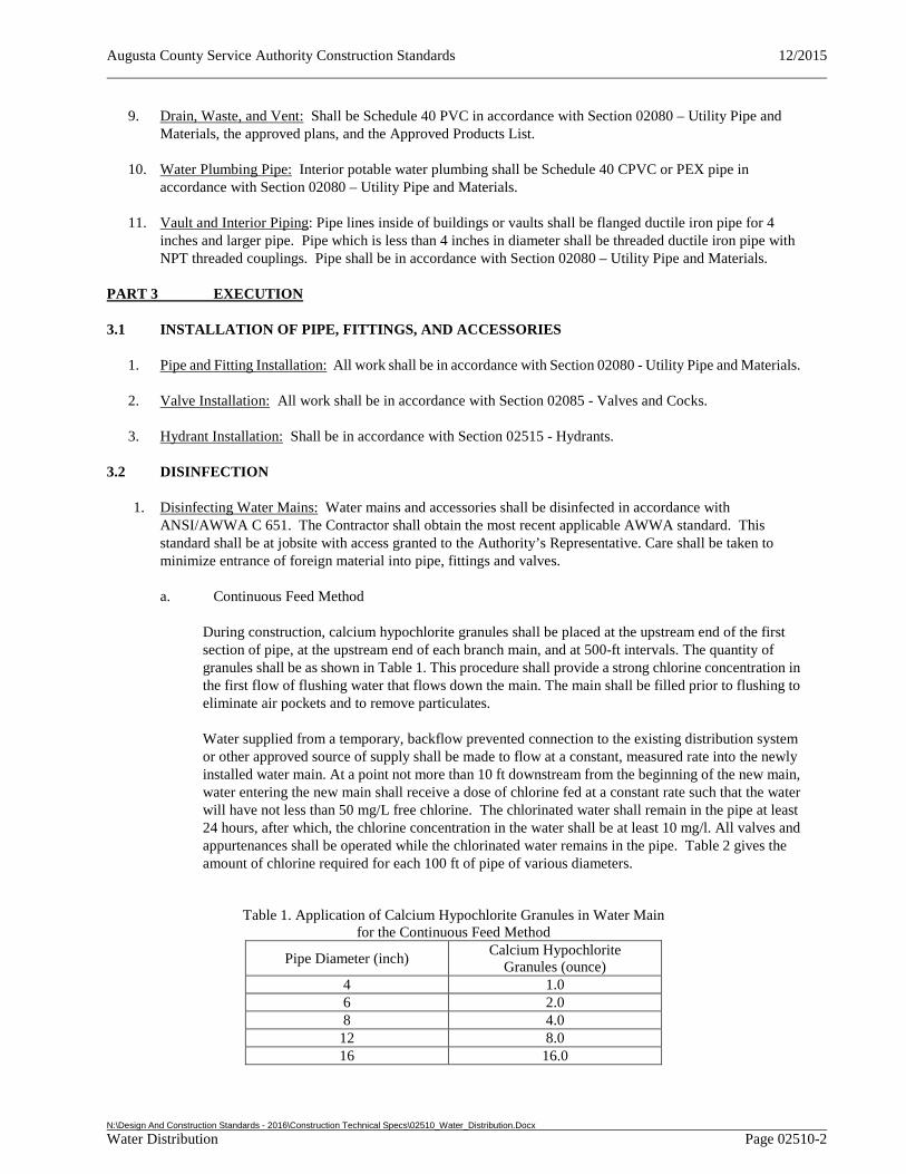
Augusta County Service Authority Construction Standards 12/2015
N:\Design And Construction Standards - 2016\Construction Technical Specs\02510_Water_Distribution.Docx Water Distribution Page 02510-2
9. Drain, Waste, and Vent: Shall be Schedule 40 PVC in accordance with Section 02080 – Utility Pipe and Materials, the approved plans, and the Approved Products List.
10. Water Plumbing Pipe: Interior potable water plumbing shall be Schedule 40 CPVC or PEX pipe in accordance with Section 02080 – Utility Pipe and Materials.
11. Vault and Interior Piping: Pipe lines inside of buildings or vaults shall be flanged ductile iron pipe for 4 inches and larger pipe. Pipe which is less than 4 inches in diameter shall be threaded ductile iron pipe with NPT threaded couplings. Pipe shall be in accordance with Section 02080 – Utility Pipe and Materials.
PART 3 EXECUTION
3.1 INSTALLATION OF PIPE, FITTINGS, AND ACCESSORIES
1. Pipe and Fitting Installation: All work shall be in accordance with Section 02080 - Utility Pipe and Materials.
2. Valve Installation: All work shall be in accordance with Section 02085 - Valves and Cocks.
3. Hydrant Installation: Shall be in accordance with Section 02515 - Hydrants.
3.2 DISINFECTION
1. Disinfecting Water Mains: Water mains and accessories shall be disinfected in accordance with ANSI/AWWA C 651. The Contractor shall obtain the most recent applicable AWWA standard. This standard shall be at jobsite with access granted to the Authority’s Representative. Care shall be taken to minimize entrance of foreign material into pipe, fittings and valves.
a. Continuous Feed Method
During construction, calcium hypochlorite granules shall be placed at the upstream end of the first section of pipe, at the upstream end of each branch main, and at 500-ft intervals. The quantity of granules shall be as shown in Table 1. This procedure shall provide a strong chlorine concentration in the first flow of flushing water that flows down the main. The main shall be filled prior to flushing to eliminate air pockets and to remove particulates.
Water supplied from a temporary, backflow prevented connection to the existing distribution system or other approved source of supply shall be made to flow at a constant, measured rate into the newly installed water main. At a point not more than 10 ft downstream from the beginning of the new main, water entering the new main shall receive a dose of chlorine fed at a constant rate such that the water will have not less than 50 mg/L free chlorine. The chlorinated water shall remain in the pipe at least 24 hours, after which, the chlorine concentration in the water shall be at least 10 mg/l. All valves and appurtenances shall be operated while the chlorinated water remains in the pipe. Table 2 gives the amount of chlorine required for each 100 ft of pipe of various diameters.
Table 1. Application of Calcium Hypochlorite Granules in Water Main
for the Continuous Feed Method
Pipe Diameter (inch) Calcium Hypochlorite
Granules (ounce) 4 1.0 6 2.0 8 4.0
12 8.0 16 16.0
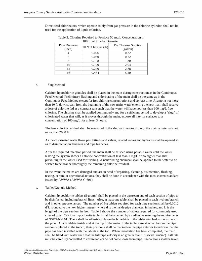
Augusta County Service Authority Construction Standards 12/2015
N:\Design And Construction Standards - 2016\Construction Technical Specs\02510_Water_Distribution.Docx Water Distribution Page 02510-3
Direct feed chlorinators, which operate solely from gas pressure in the chlorine cylinder, shall not be used for the application of liquid chlorine.
Table 2. Chlorine Required to Produce 50 mg/L Concentration in 100 ft. of Pipe by Diameter.
Pipe Diameter (inch)
100% Chlorine (lb) 1% Chlorine Solution
(gallon) 4 0.026 0.32 6 0.060 0.72 8 0.108 1.30
10 0.170 2.04 12 0.240 2.88 16 0.434 5.20
b. Slug Method
Calcium hypochlorite granules shall be placed in the main during construction as in the Continuous Feed Method. Preliminary flushing and chlorinating of the main shall be the same as in the Continuous Feed Method except for free chlorine concentrations and contact time. At a point not more than 10 ft. downstream from the beginning of the new main, water entering the new main shall receive a dose of chlorine fed at a constant rate such that the water will have not less than 100 mg/L free chlorine. The chlorine shall be applied continuously and for a sufficient period to develop a "slug" of chlorinated water that will, as it moves through the main, expose all interior surfaces to a concentration of 100 mg/L for at least 3 hours.
The free chlorine residual shall be measured in the slug as it moves through the main at intervals not more than 2000 ft.
As the chlorinated water flows past fittings and valves, related valves and hydrants shall be opened so as to disinfect appurtenances and pipe branches.
After the required retention period, the main shall be flushed using potable water until the water leaving the system shows a chlorine concentration of less than 1 mg/L or no higher than that prevailing in the water used for flushing. A neutralizing chemical shall be applied to the water to be wasted to neutralize thoroughly the remaining chlorine residual.
In the event the mains are damaged and are in need of repairing, cleaning, disinfection, flushing, testing, or similar operational actions, they shall be done in accordance with the most current standard issued by AWWA (AWWA C-601).
c. Tablet/Granule Method
Calcium hypochlorite tablets (5-grams) shall be placed in the upstream end of each section of pipe to be disinfected, including branch lines. Also, at least one tablet shall be placed in each hydrant branch and in other appurtenances. The number of 5-g tablets required for each pipe section shall be 0.0012 d2L rounded to the next higher integer, where d is the inside pipe diameter, in inches, and L is the length of the pipe section, in feet. Table 3 shows the number of tablets required for commonly used sizes of pipe. Calcium hypochlorite tablets shall be attached by an adhesive meeting the requirements of NSF/ANSI 61. There shall be adhesive only on the broadside of the tablet attached to the surface of the pipe. Attach tablets inside and at the top of the main. If the tablets are attached before the pipe section is placed in the trench, their positions shall be marked on the pipe exterior to indicate that the pipe has been installed with the tablets at the top. When installation has been completed, the main shall be filled with water such that the full pipe velocity is no greater than 1 ft/sec (0.3 m/sec). Fill rate must be carefully controlled to ensure tablets do not come loose from pipe. Precautions shall be taken
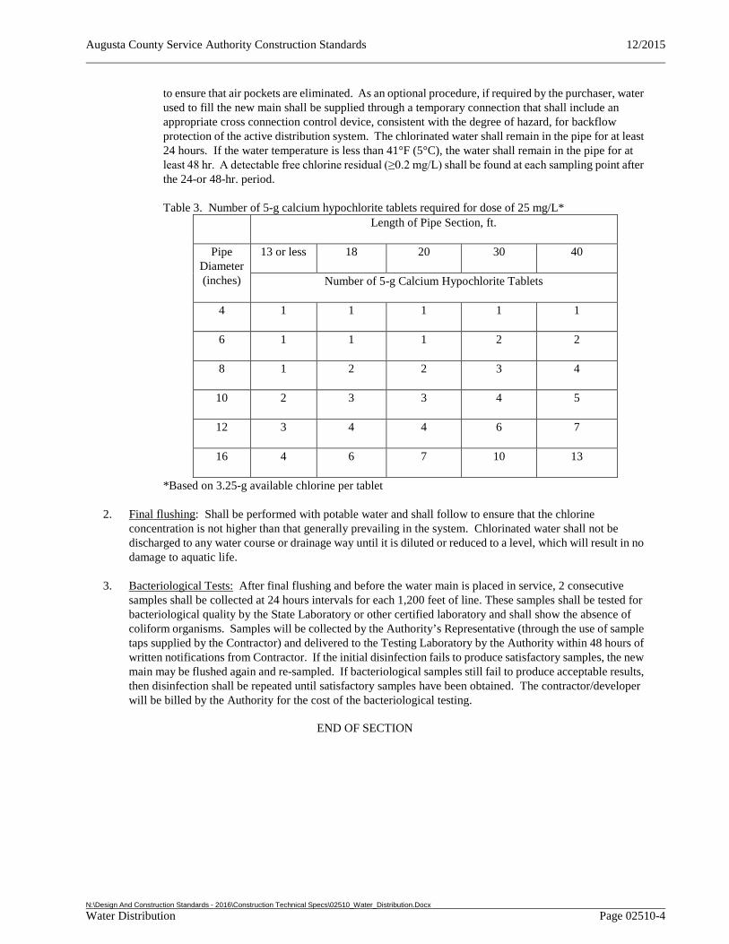
Augusta County Service Authority Construction Standards 12/2015
N:\Design And Construction Standards - 2016\Construction Technical Specs\02510_Water_Distribution.Docx Water Distribution Page 02510-4
to ensure that air pockets are eliminated. As an optional procedure, if required by the purchaser, water used to fill the new main shall be supplied through a temporary connection that shall include an appropriate cross connection control device, consistent with the degree of hazard, for backflow protection of the active distribution system. The chlorinated water shall remain in the pipe for at least 24 hours. If the water temperature is less than 41°F (5°C), the water shall remain in the pipe for at least 48 hr. A detectable free chlorine residual (≥0.2 mg/L) shall be found at each sampling point after the 24-or 48-hr. period.
Table 3. Number of 5-g calcium hypochlorite tablets required for dose of 25 mg/L* Length of Pipe Section, ft.
Pipe Diameter (inches)
13 or less 18 20 30 40
Number of 5-g Calcium Hypochlorite Tablets
4 1 1 1 1 1
6 1 1 1 2 2
8 1 2 2 3 4
10 2 3 3 4 5
12 3 4 4 6 7
16 4 6 7 10 13
*Based on 3.25-g available chlorine per tablet
2. Final flushing: Shall be performed with potable water and shall follow to ensure that the chlorine concentration is not higher than that generally prevailing in the system. Chlorinated water shall not be discharged to any water course or drainage way until it is diluted or reduced to a level, which will result in no damage to aquatic life.
3. Bacteriological Tests: After final flushing and before the water main is placed in service, 2 consecutive samples shall be collected at 24 hours intervals for each 1,200 feet of line. These samples shall be tested for bacteriological quality by the State Laboratory or other certified laboratory and shall show the absence of coliform organisms. Samples will be collected by the Authority’s Representative (through the use of sample taps supplied by the Contractor) and delivered to the Testing Laboratory by the Authority within 48 hours of written notifications from Contractor. If the initial disinfection fails to produce satisfactory samples, the new main may be flushed again and re-sampled. If bacteriological samples still fail to produce acceptable results, then disinfection shall be repeated until satisfactory samples have been obtained. The contractor/developer will be billed by the Authority for the cost of the bacteriological testing.
END OF SECTION
Augusta County Service Authority Construction Standards 12/2015
N:\Design And Construction Standards - 2016\Construction Technical Specs\02515_Hydrants.Doc Hydrants Page 02515-1
SECTION 02515 - HYDRANTS
PART 1 GENERAL
1.1 REFERENCES
1. General: The work shall comply with the most recent standards or tentative standards as published at the date of the contract and as listed in this specification using the abbreviation shown.
2. American National Standards Institute (ANSI)/American Water Works Association (AWWA):
a. C 502 Standard for Hydrants, Dry Barrel Fire Hydrants (Includes addendum C 502a-95)
PART 2 PRODUCTS
2.1 EQUIPMENT
1. Fire Hydrants: Shall be traffic type with safety flange protection conforming to ANSI/AWWA C 502 and shall have not less than 6 inch diameter barrel, 4-1/2 inch minimum hydrant valve and a measured loss of not more than 2.5 psi through the hydrant at 600 gpm. Hydrant shall have a 6 inch mechanical joint connection to the water main, two 2-1/2 inch hose outlets and one 4-1/2 inch pumper outlet and be so designed that if broken off, the hydrant valve will remain closed. Minimum bury depth shall be 3-1/2 feet or to accommodate depth of water main. Direction of opening shall be left (counterclockwise) with 1-1/2 inch pentagon shape operating nut, and nozzle threading shall be National Standard. Hydrants shall be per the Approved Products List.
Hydrants to be accepted into the Authority’s water system shall be painted in accordance with the Approved Products List.
Hydrants which will remain a part of a private water system shall be painted in accordance with the following:
Hydrant: Safety Red Caps: Safety Red
2. Blowoff Hydrants: Blowoff hydrant shall be non-freezing post hydrant self draining type, furnished with a 2 inch FIP inlet, a non-turning operating rod, and shall open counter-clockwise. All of the working parts shall be of bronze-to-bronze design, and be serviceable from above grade without excavation. The outlet shall also be bronze 2-1/2 inch NST and fitted with a protective cap. Hydrants shall be lockable to prevent unauthorized use.
Provisions shall be made for blow-off assemblies at the ends of any approved dead end lines by means of a regular blow-off assembly or hydrant, as may be directed by the Authority (see Standard Detail). Blow-off assemblies shall be placed behind the curb. No flushing device shall be directly connected to any sewer. Chambers or pits containing blow-offs shall be drained to the surface of the ground where they are not subject to flooding from surface water, or to absorption pits located above the seasonal groundwater table.
Augusta County Service Authority Construction Standards 12/2015
N:\Design And Construction Standards - 2016\Construction Technical Specs\02515_Hydrants.Doc Hydrants Page 02515-2
PART 3 EXECUTION
3.1 INSTALLATION
1. General: Installation shall be in accordance with the manufacturer's instructions and Standard Details. Hydrants and their gate valves shall be restrained to the main water line such that the hydrant could be removed and the valve would still be restrained to the main water line.
2. Hydrant Location: Fire hydrants should be located two to ten feet from the curb or outside edge of the shoulder and five feet from fixed objects with the pumper connection facing the street. Fire hydrants shall be set so that the traffic flange is 2 inches above finished grade, and shall be supported per the manufacturers’ recommendations so that the drain line is not obstructed and no load transfers to the pipe.
3. Blowoff Hydrants: The installation of blowoff hydrants shall be in accordance with the manufacturers’ instructions.
4. Hydrant Disassembly: Should the need arise for disassembling the hydrant, such as for adding extensions, a brass sleeve shall be employed to protect the oil seals from damage when removing the hydrant housing from the upper stem.
END OF SECTION
Augusta County Service Authority Construction Standards 12/2015
N:\Design And Construction Standards - 2016\Construction Technical Specs\02530_Sanitary_Sewerage_Systems.Docx Sanitary Sewerage Systems Page 02530-1
SECTION 02530 - SANITARY SEWERAGE SYSTEMS
PART 1 GENERAL
1.1 REFERENCES
1. General: The work shall comply with the most recent standards or tentative standards as published at the date of the contract and as listed in this specification using the abbreviation shown.
2. Related Sections: Additional Sections of the Documents which are referenced in this Section include:
a. Section 02080 - Utility Pipe and Materials
b. Section 02085 - Valves and Cocks
c. Section 11315 - Wastewater Pump Station
PART 2 PRODUCTS
2.1 GRAVITY SEWER
1. Gravity Sewer Pipe 4 inch to 15 inch: Gravity sewer pipe shall be PVC SDR 35, PVC C900, or in special cases ductile iron pipe thickness Class 50 may be approved or required depending on field conditions. in accordance with the plans and with Section 02080 – Utility Pipe and Materials. The Service Authority reserves the right to select the type of pipe material which shall be used in sewer installation from the Authority's Approved Products List. Sewers installed with 15 feet of cover or greater shall be constructed of PVC C900 pipe.
2. Gravity Sewer Pipe 18 inch to 36 inch: Shall be PVC in accordance with Section 02080 – Utility Pipe and Materials (ASTM F679) and Approved Products List.
3. Gravity Sewer Pipe larger than 36 inch: Consult Service Authority Engineering Department.
4. Fittings: Tees, wyes, or other miscellaneous fittings shall be of the same material and type as the gravity sewer pipe provided.
2.2 FORCE MAIN
1. General: Pressure pipe for force main installation shall be ductile iron pipe thickness class 50. Pipe and fittings shall be in accordance with Section 02080 – Utility Pipe and Materials.
2. Fittings: Underground fittings shall be restrained, mechanical joint ductile iron fittings except where specifically noted on plans.
2.3 MANHOLES AND STRUCTURES
1. Manhole: Manholes shall be in accordance with Section 02080 – Utility Pipe and Materials.
2.4 VALVES AND BOXES
1. Valves: Force main valves, when shown on plans, shall be plug valves in accordance with Section 02085 – Valves and Cocks.
Augusta County Service Authority Construction Standards 12/2015
N:\Design And Construction Standards - 2016\Construction Technical Specs\02530_Sanitary_Sewerage_Systems.Docx Sanitary Sewerage Systems Page 02530-2
2. Valve Boxes: Valve boxes or vaults shall be provided for all underground valves. Valve boxes shall be in accordance with Section 02080 – Utility Pipe and Materials and applicable Standard Details. Valve vaults shall be precast in accordance with Section 02080 – Utility Pipe and Materials.
2.5 PUMP STATION EQUIPMENT
1. General: Pump station equipment, pumps, controls and related hardware shall be in accordance with Section 11315 - Wastewater Pump Stations.
PART 3 EXECUTION
3.1 SEPARATION OF WATER LINES AND SEWERS
1. General: Sanitary sewer shall be separated from water lines in accordance with the Virginia Waterworks Regulations and Section 02080 – Utility Pipe and Materials.
3.2 INSTALLATION OF PIPE, FITTINGS, AND PRECAST STRUCTURES
1. General: Installation and testing of pipe, fittings, and appurtenances shall be in accordance with Section 02080 – Utility Pipe and Materials.
END OF SECTION
Augusta County Service Authority Construction Standards 12/2015
N:\Design and Construction Standards - 2016\Construction Technical Specs\02821_Chain_Link_Fences.doc Chain-Link Fences And Gates Page 02821 - 1
SECTION 02821 – CHAIN LINK FENCES AND GATES
PART 1 - GENERAL
1.1 DESCRIPTION
1. Work Included: Furnish and supply all materials, equipment, and labor for chain link fences as shown on the plans and specified hereunder.
1.2 PERFORMANCE REQUIREMENTS
1. Structural Performance: Provide chain-link fences capable of withstanding the effects of gravity loads and the following loads and stresses within limits and under conditions indicated:
a. Minimum Post Size and Maximum Spacing for Wind Velocity Pressure: Determine based on mesh size and pattern specified, and on the following minimum design wind pressures and according to CLFMI WLG 2445.
b. Determine minimum post size, group, and section according to ASTM F 1043 for framework up to 12 feet high, and post spacing not to exceed 10 feet.
2. Lightning Protection System: Maximum grounding-resistance value of 25 ohms under normal dry conditions.
1.3 SUBMITTALS
1. Product Data: Include construction details, material descriptions, dimensions of individual components and profiles, and finishes for chain-link fences.
a. Fence posts, rails, and fittings.
b. Chain-link fabric, reinforcements, and attachments.
c. Hardware.
d. Accessories: Barbed wire.
2. Shop Drawings: Show locations of fences, posts, rails, tension wires, details of extended posts, extension arms, or other operation, hardware, and accessories. Indicate materials, dimensions, sizes, weights, and finishes of components. Include plans, elevations, sections, details of post anchorage, attachment, bracing, and other required installation and operational clearances.
3. Product Certificates: For each type of chain-link fence signed by product manufacturer.
a. Strength test results for framing according to ASTM F 1043.
4. Qualification Data: For Installer.
5. Field quality-control test reports.
Augusta County Service Authority Construction Standards 12/2015
N:\Design and Construction Standards - 2016\Construction Technical Specs\02821_Chain_Link_Fences.doc Chain-Link Fences And Gates Page 02821 - 2
1.4 QUALITY ASSURANCE
1. Installer Qualifications: An experienced installer who has completed chain-link fences similar in material, design, and extent to those indicated for this Project and whose work has resulted in construction with a record of successful in-service performance.
a. Engineering Responsibility: Preparation of data for chain-link fences, including Shop Drawings, based on testing and engineering analysis of manufacturer's standard units in assemblies similar to those indicated for this Project.
1.5 REFERENCES
1. ASTM 123 Standard Specification for Zinc (Hot-Dip Galvanized) Coatings on Iron and Steel.
2. ASTM F 1043 Standard Specification for Strength and Protective Coatings on Steel Industrial Chain Like Fence Framework.
3. CLFMI (WLG 2445) Chain Link Fence Wind Load Guide for the Selection of Line Post and Line Post Spacing.
1.6 PROJECT CONDITIONS
1. Field Measurements: Verify layout information for chain-link fences shown on Drawings in relation to property survey and existing structures. Verify dimensions by field measurements.
PART 2 - PRODUCTS
2.1 MATERIAL REQUIREMENTS
1. Shall apply to any facility location.
2.2 CHAIN-LINK FENCE FABRIC
1. General: Provide fabric in one-piece heights measured between top and bottom of outer edge of selvage knuckle or twist. Comply with ASTM A 392, CLFMI CLF 2445, and requirements indicated below:
a. Steel Wire Fabric: Metallic-coated wire with a diameter of 0.192 inch. i. Mesh size: 2-1/8 inches.
ii. Weight of Metallic (Zinc) Coating: ASTM A 392, Type II, Class 1, 1.2 oz./sq. ft. with zinc coating applied after weaving.
b. Selvage: Twisted top and knuckled bottom.
2.3 NDUSTRIAL FENCE FRAMING
1. Posts and Rails: Comply with ASTM F 1043 for framing, ASTM F 1083 for round pipe, and the following:
a. Group: IA, round steel pipe, Schedule 40.
Augusta County Service Authority Construction Standards 12/2015
N:\Design and Construction Standards - 2016\Construction Technical Specs\02821_Chain_Link_Fences.doc Chain-Link Fences And Gates Page 02821 - 3
b. Fence Height: i. Perimeter Fence: 6’ high fabric with 3-strand barbed wire on angled support arms.
c. Strength Requirement: Light industrial according to ASTM F 1043.
d. Post Diameter and Thickness: According to ASTM F 1043. i. Gate Post: According to ASTM F 900.
e. Coating for Steel Framing: i. Metallic Coating:
1. Type A, consisting of not less than minimum 2.0-oz./sq. ft. average zinc coating per ASTM A 123/A 123M or 4.0-oz./sq. ft. zinc coating per ASTM A 653/A 653M.
2.4 TENSION WIRE
1. General: Provide horizontal tension wire at the following locations:
a. Location: Extended along top and bottom of fence fabric.
2. Metallic-Coated Steel Wire: 0.177-inch- diameter, marcelled tension wire complying with ASTM A 817, ASTM A 824, and the following:
a. Metallic Coating: Type II, zinc coated (galvanized), with the following minimum coating weight: i. Matching chain-link fabric coating weight.
2.5 FITTINGS
1. General: Comply with ASTM F 626.
2. Barbed Wire Arms: Pressed steel or cast iron, with clips, slots, or other means for attaching strands of barbed wire, and means for attaching to posts, or integral with post cap; for each post, unless otherwise indicated, and as follows:
a. Line posts with arms that accommodate top rail or tension wire.
b. Corner arms at fence corner posts, unless extended posts are indicated.
c. Type I, single slanted arm for three strands of barbed wire.
2.6 GATE
1. General: Gate shall be counterbalanced sliding type of full fence height and width as shown on plans. Swing type will be allowed at ACSA’s discretion dependent upon the location in proximity to traffic or other site conditions. Gate frame shall be constructed of heavy duty round steel tubing and provided with chain-link fabric and barbed wire matching the main fence. Steel or nylon rollers shall be attached to the mounting posts to fully support the gate. Counterbalance length shall be no more than 50% of opening width. Supplier is responsible for designing support system to be compatible with fence dimensions and layout shown. Gate shall include padlockable gate latch. Swing gates are permissible where grades or other obstructions prevent the safe installation/use of a sliding type gate.
2.7 BARBED WIRE
1. Zinc-Coated Steel Barbed Wire: Comply with ASTM A 121, Standard grade for the following two-strand barbed wire:
Augusta County Service Authority Construction Standards 12/2015
N:\Design and Construction Standards - 2016\Construction Technical Specs\02821_Chain_Link_Fences.doc Chain-Link Fences And Gates Page 02821 - 4
a. Standard Size and Construction: 0.099-inch- diameter line wire with 0.080-inch- diameter, 2-point round barbs spaced not more than 5 inches o.c.
2.8 GROUT AND ANCHORING CEMENT
1. Nons-hrink, Nonmetallic Grout: Premixed, factory-packaged, non-staining, noncorrosive, nongaseous grout complying with ASTM C 1107. Provide grout, recommended in writing by manufacturer, for exterior applications.
2. Erosion-Resistant Anchoring Cement: Factory-packaged, non-shrink, non-staining, hydraulic-controlled expansion cement formulation for mixing with potable water at Project site to create pourable anchoring, patching, and grouting compound. Provide formulation that is resistant to erosion from water exposure without needing protection by a sealer or waterproof coating and that is recommended in writing by manufacturer, for exterior applications.
PART 3 - EXECUTION
3.1 EXAMINATION
1. Examine areas and conditions, with Installer present, for compliance with requirements for site clearing, earthwork, pavement work, and other conditions affecting performance.
a. Do not begin installation before final grading is completed, unless otherwise permitted by ENGINEER.
b. Proceed with installation only after unsatisfactory conditions have been corrected.
3.2 PREPARATION
1. Stake locations of fence lines, gates, and terminal posts. Do not exceed intervals of 500 feet or line of sight between stakes. Indicate locations of utilities, lawn sprinkler system, underground structures, benchmarks, and property monuments.
3.3 INSTALLATION, GENERAL
1. Install chain-link fencing to comply with ASTM F 567 and more stringent requirements specified.
3.4 CHAIN-LINK FENCE INSTALLATION
1. Post Excavation: Drill or hand-excavate holes for posts to diameters and spacings indicated, in firm, undisturbed soil.
2. Post Setting: Set terminal posts in concrete and in-line posts with mechanical anchors or by mechanically driving into soil at indicated spacing into firm, undisturbed soil.
a. Verify that posts are set plumb, aligned, and at correct height and spacing, and hold in position during setting with concrete or mechanical devices.
b. Concrete Fill: Place concrete around posts to dimensions indicated and vibrate or tamp for consolidation. Protect aboveground portion of posts from concrete splatter.
Augusta County Service Authority Construction Standards 12/2015
N:\Design and Construction Standards - 2016\Construction Technical Specs\02821_Chain_Link_Fences.doc Chain-Link Fences And Gates Page 02821 - 5
i. Exposed Concrete: Extend 2 inches above grade; shape and smooth to shed water.
c. Mechanically Driven Posts: Drive into soil to depth of 36 inches. Protect post top to prevent distortion.
3. Terminal Posts: Locate terminal end, corner, and gate posts per ASTM F 567 and terminal pull posts at changes in horizontal or vertical alignment of 15 degrees or more.
4. Line Posts: Space line posts uniformly at 10 feet o.c.
5. Post Bracing and Intermediate Rails: Install according to ASTM F 567, maintaining plumb position and alignment of fencing. Install braces at end and gate posts and at both sides of corner and pull posts.
a. Locate horizontal braces at mid-height of fabric 6 feet or higher, on fences with top rail and at 2/3 fabric height on fences without top rail. Install so posts are plumb when diagonal rod is under proper tension.
6. Tension Wire: Install according to ASTM F 567, maintaining plumb position and alignment of fencing. Pull wire taut, without sags. Fasten fabric to tension wire with 0.120-inch- diameter hog rings of same material and finish as fabric wire, spaced a maximum of 24 inches o.c. Install tension wire in locations indicated before stretching fabric.
a. Top Tension Wire: Install tension wire through post cap loops.
b. Bottom Tension Wire: Install tension wire within 6 inches of bottom of fabric and tie to each post with not less than same diameter and type of wire.
7. Chain-Link Fabric: Apply fabric to outside of enclosing framework. Leave 2 inches between finish grade or surface and bottom selvage, unless otherwise indicated. Pull fabric taut and tie to posts, rails, and tension wires. Anchor to framework so fabric remains under tension after pulling force is released.
8. Tension or Stretcher Bars: Thread through fabric and secure to end, corner, pull, and gate posts with tension bands spaced not more than 15 inches o.c.
9. Tie Wires: Use wire of proper length to firmly secure fabric to line posts and rails. Attach wire at 1 end to chain-link fabric, wrap wire around post a minimum of 180 degrees, and attach other end to chain-link fabric per ASTM F 626. Bend ends of wire to minimize hazard to individuals and clothing.
a. Maximum Spacing: Tie fabric to line posts at 12 inches o.c. and to braces at 24 inches o.c.
10. Fasteners: Install nuts for tension bands and carriage bolts on the side of the fence opposite the fabric side.
11. Barbed Wire: Install barbed wire uniformly spaced, angled toward security side of fence. Pull wire taut and install securely to extension arms and secure to end post or terminal arms.
END OF SECTION
Augusta County Service Authority Construction Standards 12/2015
N:\Design and Construction Standards - 2016\Construction Technical Specs\03310_Insulated_Concrete_Forms.doc Insulated Concrete Forms Page 03310-1
SECTION 03310 –INSULATED CONCRETE FORMS
PART 1 GENERAL
1.1 DESCRIPTION
1. Work Included: Supply and installation of Insulating Concrete Forms (ICF) for structural cast-in-place concrete walls, installation of reinforcing steel bars and placement of concrete within the insulating concrete forms.
2. Related Sections: Additional Sections of the Documents which are referenced in this Section include:
a. Section 01330 – Submittal Procedures
b. Section 01610 – Delivery, Storage, and Handling
c. Section 02200 – Site Construction
1.2 SYSTEM DESCRIPTION
1. General: ICF form blocks consist of two EPS foam plastic boards separated by injection molded polypropylene webs. The webs are sized to maintain concrete core thicknesses as indicated on the plans. The polypropylene webs have 1.5 inches wide by 15 inches high flanges embedded ½ inch below outside surface of the EPS foam boards to provide attachment for exterior and interior wall finishes.
1.3 SUBMITTALS
1. General: Comply with pertinent provisions of Section 01330 - Submittal Procedures.
2. Product Data: Submit manufacturer’s specifications and instructions for manufactured materials and products. Include manufacturer’s certifications and laboratory test reports as required.
3. Shop Drawings: Submit shop drawings showing complete information for fabrication and installation of precast concrete units. Indicate member dimensions and cross-section; location, size and type of reinforcement, including special reinforcement and lifting devices necessary for handling and erection.
4. Steel Reinforcement: Submit schedule of reinforcing steel.
5. Design: Provide complete design calculations prepared and sealed by a registered professional engineer licensed to practice in the Commonwealth of Virginia. Shop drawings shall also be sealed by a registered professional engineer licensed to practice in the Commonwealth of Virginia.
1.4 DELIVERY, STORAGE, AND HANDLING
1. General: Comply with pertinent provision of Section 01610 – Delivery, Storage, and Handling.
2. Storage and Handling: Store materials in manufacturer provided bundles, to prevent damage. Protect from extended exposure to direct sunlight. Handle and store product in a location to prevent physical damage and soiling.
Augusta County Service Authority Construction Standards 12/2015
N:\Design and Construction Standards - 2016\Construction Technical Specs\03310_Insulated_Concrete_Forms.doc Insulated Concrete Forms Page 03310-2
PART 2 PRODUCTS
2.1 INSULATED CONCRETE FORMS
1. Expanded Polystyrene: Expanded Polystyrene Type II Requirements as per ASTM C578-95 Standard Specification for Rigid Cellular Polystyrene Thermal Insulation as follows:
a. Density (ASTM C 1622-98) = 1.5 lbs/ft3
b. Thermal Resistance (ASTM C 177-97) = 4.0 F.ft2.h/Btu
c. Compressive Strength (ASTM D 1621-94) = 19.8 psi
d. Flexural Strength (ASTM C 203-99) = 42.57 psi
e. Water Vapor Permeance (ASTM E-96-94) = 130.1 ng/Pa.s.m2
f. Water Absorption (ASTM C 272-91) = 2.95%
g. Dimensional Stability (ASTM D 2126-94) = 0.52%
h. Limiting Oxygen Index (ASTM D 2863-97) = 37%
i. Trueness and Squareness (ASTM C 550-95)
2. Form Ties: Mechanical and Physical Properties of Plastic Tie and Interlocking Profiles in accordance with ICBOES AC116 “ Acceptance Criteria for Nail & Spikes” and in conjunction with ASTM D 1761 (Standard Test Methods for Mechanical Fasteners in Wood) and also in accordance with CCMC Technical Guide for “ Modular Polystyrene Concrete Forms’ are as follows:
a. Type ‘S’ Fine thread drywall screw withdrawal load = 39.61 lbs (safety factor of 5)
b. Type ‘S’ Fine thread drywall lateral resistance load = 60.22 lbs (safety factor of 3.2)
c. Type ‘W’ coarse thread drywall screw withdrawal load= 38.42 lbs (safety factor of 5)
d. Type ‘W’ coarse thread drywall lateral resistance load = 50.56 lbs (safety factor of 4.46)
e. Tensile strength of web (ASTM D 638-99) = 253.3 lbs (safety factor of 3.2)
f. Ignition Temperature (ASTM D 1929-68) = 400°C (752°F),
g. Burn Rate (ASTM D 635-98) = 20.2 mm/min
h. Smoke Density (ASTM D 2843-93 / UBC 26-5) = 25.8%
3. Fire Rating: Fire Rating in accordance with CAN/ULC S101-M89 and ASTM E119 “Standard Test Methods for Fire Tests of Building Construction and Materials”. 6 inches concrete core (152mm) with 2.5 inches of EPS foam on both sides under load bearing conditions shall have a minimum fire rating of 3 hours.
4. R-Value: Minimum calculated R-Value shall be 22 for wall assembly including exterior and interior foam panels, concrete core, stucco exterior and interior finish.
Augusta County Service Authority Construction Standards 12/2015
N:\Design and Construction Standards - 2016\Construction Technical Specs\03310_Insulated_Concrete_Forms.doc Insulated Concrete Forms Page 03310-3
5. Sound Transmission: Minimum Sound Transmission Class (STC) of 50 for wall assembly including exterior and interior foam panels, concrete core, stucco exterior and interior finish.
2.2 CONCRETE
1. General: Concrete for wall core shall conform to requirements of Section 02200 – “Site Construction”.
2.3 STEEL
1. General: Steel reinforcement for wall core shall conform to requirements of Section 02200 – “Site Construction”.
2.4 MANUFACTURED UNITS
1. General: Two opposing faces of expanded polystyrene connected with polypropylene webs placed vertically 6 inches on center. Each web shall have support slots for horizontal reinforcing, and end plates on each side of the block for attaching interior and exterior finishes. Forms shall be preformed with interlocking edge to secure courses together.
2. Standard Reversible Straight Form Units:
a. 4 inch wall width: Block Size 48 inches by 16 inches by 9 inches
b. 6 inch wall width: Block Size 48 inches by 16 inches by 11 inches
c. 8 inch wall width: Block Size 48 inches by 16 inches by 13 inches
d. 10 inch wall width: Block Size 48 inches by 24 inches by 15 inches
3. Standard 90° Reversible Corner Form Units:
a. 4 inch wall width: Block Size (36 1/2 inches +12 1/2 inches) by 16 inches by 9 inches
b. 6 inch wall width: Block Size (26 1/2 inches +14 1/2 inches) by 16 inches by 11 inches
c. 8 inch wall width: Block Size (28 1/2 inches +16 1/2 inches) by 16 inches by 13 inches
d. 10 inch wall width: Block Size (42 1/2 inches +18 1/2 inches) by 24 inches by 15 inches
PART 3 EXECUTION
3.1 GENERAL
1. Site Verification of Conditions: Verify lines, levels and centers before proceeding with formwork. Ensure dimension agree with drawings.
2. Surface Preparation: Work surfaces such as footings and slabs on which precast units or panels are to be erected, shall be kept clean and free of dirt and debris. Soiled surfaces shall be pressure washed, and when applicable dried, prior to the application of joint sealants.
Augusta County Service Authority Construction Standards 12/2015
N:\Design and Construction Standards - 2016\Construction Technical Specs\03310_Insulated_Concrete_Forms.doc Insulated Concrete Forms Page 03310-4
3.2 INSTALLATION
1. General: Install Insulating Concrete Forming in accordance with manufacturer’s installation methods.
a. Protect forms from damage.
b. Install formwork, shoring and bracing to achieve design requirements and in accordance with ACI 301.
c. Provide bracing to ensure stability of formwork. Shore or strengthen formwork subject to over stressing by construction loads. Reinforce all cuts and weak spots.
d. Align joints and install forms in a running bond pattern
e. Assure alignment of polypropylene furring strips to facilitate wall covering attachment.
f. Install reinforcing, as indicated in engineered shop drawings, over opening to provide for integral lintels with the wall.
2. Interface with Other Work: Provide formed openings where required for items to be embedded in or to pass through concrete work. Locate and set items to be cast directly into concrete. Coordinate with work of other trades in forming and placing openings, sleeves, bolts, anchors, other inserts. Install accessories in accordance with manufacturer’s instructions, straight, level and plumb. Ensure items are not disturbed during concrete placement.
3.3 FIELD QUALITY CONTROL
1. General: Inspect erected formwork, shoring and bracing to ensure that work is in accordance with design, and that elements are secure.
3.4 CLEANING
1. General: Clean forms as installation proceeds, to remove foreign matter within forms. Clean formed cavities of debris prior to placing concrete. Flush with water or use compressed air to remove remaining foreign matter. Ensure that water and debris drain to exterior through clean-out ports. During cold weather, remove ice and snow from within forms. Do not use de-icing salts. Do not use water to clean out forms. Use compressed air or other means to remove foreign matter.
END OF SECTION
Augusta County Service Authority Construction Standards 12/2015
N:\Design And Construction Standards - 2016\Construction Technical Specs\03400_Precast_Concrete_Structure.Doc Precast Concrete Structures Page 03400-1
SECTION 03400 –PRECAST CONCRETE STRUCTURES
PART 1 GENERAL
1.1 DESCRIPTION
1. Work Included: Erection of all structural precast concrete units as shown on the plans.
2. Related Sections: Additional Sections of the Documents which are referenced in this Section include:
a. Section 01610 – Delivery, Storage, and Handling
b. Section 02080 – Utility Pipe and Materials
c. Section 02200 – Site Construction
1.2 SYSTEM DESCRIPTION
1. General: Precast units shall have the same internal dimensions as those shown on the plans and must have internal walls as shown where applicable.
1.3 SUBMITTALS
1. Product Data: Submit manufacturer’s specifications and instructions for manufactured materials and products. Include manufacturer’s certifications and laboratory test reports as required.
2. Shop Drawings: Submit shop drawings showing complete information for fabrication and installation of precast concrete units. Indicate member dimensions and cross-section; location, size and type of reinforcement, including special reinforcement and lifting devices necessary for handling and erection.
3. Details: Indicate layout, dimensions, and identification of each precast unit corresponding to sequence and procedure of installation. Indicate welded connections by American Welding Society (AWS) standard symbols. Detail inserts, connections, and joints, including accessories and construction at opening in precast units.
4. Design: Provide complete design calculations prepared and sealed by a registered professional engineer licensed to practice in the Commonwealth of Virginia. Shop drawings shall also be sealed by a registered professional engineer licensed to practice in the Commonwealth of Virginia. The design must meet the requirements of the latest edition of ACI 318 or ACI 350R. Structure must be designed to resist buoyancy with a minimum 1.25 safety factor. Buoyancy resistance shall be calculated assuming groundwater to top of vault and vault is empty. Where extended footer is provided, only weight of soil directly above extended footer may be considered. Soil friction to sidewall may not be included in buoyancy calculation.
1.4 QUALITY ASSURANCE
1. Fabricator Qualifications: Fabricator must have sufficient production capacity to produce required units without causing delay in work. Tankage shall be designed, fabricated, and erected by a firm having a minimum of 10 years of experience in the manufacturing of tankage of a similar arrangement, using a precast design. The manufacturer shall document the installation of a minimum of ten (10) such functioning facilities during the submittal requirements.
2. Design by Fabricator: Design precast units for all dead loads and live loads as indicated and as required for compliance with applicable Building Code requirements. Walls shall be designed for water and soil pressure using water height at the grade elevation shown on the plans. If hydrostatic uplift forces exist
Augusta County Service Authority Construction Standards 12/2015
N:\Design And Construction Standards - 2016\Construction Technical Specs\03400_Precast_Concrete_Structure.Doc Precast Concrete Structures Page 03400-2
when the tank is empty, the Designer (Fabricator) shall provide for necessary hold-down items. The CONTRACTOR shall furnish and install hold-down items, if they are required.
3. Fabrication Qualifications: Produce precast concrete units at fabricating plant engaged in manufacturing of similar units, unless plant fabrication or delivery to project site is impractical.
4. Inspections: The quality of all materials, the process of manufacture, and the finished sections shall be subject to inspection and approval by the ENGINEER. Such inspection may be made at the place of manufacture, or at the work site after delivery, or at both. The materials shall be subject to rejection at any time on account of failure to meet any of the Specifications requirements; even though samples may have been accepted as satisfactory at the place of manufacture. Material rejected after delivery to the job shall be marked for identification and shall be removed from the job. All materials damaged after delivery will be rejected, and if already installed, shall be acceptably repaired, if permitted, or removed and replaced, at no additional cost to the ACSA.
1.5 DELIVERY, STORAGE, AND HANDLING
1. General: Comply with pertinent provision of Section 01610 – Delivery, Storage, and Handling.
2. Delivery: Deliver precast units to project site in such quantities and at such times to assure continuity of installation. Store units at project site to prevent cracking, distortion, staining, or other physical damage, and so that markings are visible. Lift and support units only at designated points. Deliver anchorage items which are to be embedded in other construction before start of such work. Provide setting diagrams, templates, instructions and directions as required for installation.
PART 2 PRODUCTS
2.1 MATERIALS
1. General: Concrete and reinforcing materials shall comply with Section 02200 – Site Construction except as modified by this Section.
2. Reinforcing Materials:
a. Reinforcing Bars: ASTM A615, Grade 60 unless otherwise indicated
b. Welded Wire Fabric: ASTM A185
c. Welded Deformed Steel Wire Fabric: ASTM A497
d. Supports for Reinforcement: Provide supports for reinforcement including bolsters, chairs, spacers and other devices for spacing, supporting and fastening reinforcing, complying with CRSI recommendations.
i. For exposed-to-view concrete surfaces, where legs of supports are in contact with forms, provide supports with legs which are plastic protected (CRSI, Class 1) or stainless steel protected (CRSI, Class 2).
3. Concrete Materials:
a. Portland Cement: ASTM C150, Type II
b. Compression Strength: 5000 psi @ 28 days
c. Slump: 4 inch maximum unless water reduction admixtures used
Augusta County Service Authority Construction Standards 12/2015
N:\Design And Construction Standards - 2016\Construction Technical Specs\03400_Precast_Concrete_Structure.Doc Precast Concrete Structures Page 03400-3
d. Use only one brand and type of cement throughout project, unless otherwise acceptable to the ENGINEER.
e. Aggregates: ASTM C33, and as herein specified. Provide aggregates from a single source for exposed concrete.
f. Water: Potable
g. Air-Entraining Admixture: ASTM C260
h. Water-Reducing Admixture: ASTM C494, Type A, or other type approved for fabricator’s units.
4. Proportioning and Design of Mixes:
a. Prepare design mixes for each type of concrete required.
b. Design mixes may be prepared by independent testing facility or by qualified precast manufacturing plant personnel, at precast manufacturer’s option.
c. Proportion mixes by either laboratory trail batch or field experience methods, using materials to be employed on the project for each type of concrete required, complying with ACI 318.
i. Produce standard-weight concrete consisting of specified portland cement, aggregates, admixtures, and water to produce the following properties.
ii. Compressive strength; 5000 psi minimum at 28 days. Release strength for pre-stressed units: 2500 psi.
iii. Cure compression test cylinders using same methods as used for precast concrete work.
d. Admixtures:
i. Use air-entraining admixture in concrete.
ii. Use water-reducing admixtures in strict compliance with manufacturer’s directions. Admixtures to increase cement dispersion, or provide increased workability for low-slump concrete, may be used subject to ENGINEER’S approval.
iii. Use amounts as recommended by admixture manufacturer for climatic conditions prevailing at time of placing. Adjust quantities of admixtures as required to maintain quality control.
5. Joints: The walls and bottom slab shall be poured monolithically or shall include water stops at interface of all separate pours. Top joints shall be sealed with two rings of butyl rubber rope meeting AASHTO M198, Type B.
6. Pipe Connections:
a. Provision of the indicated pipe connections in tanks shall be made by means of an approved flexible, watertight gasket or boot.
7. Grout Materials: Portland cement, ASTM C150, Type I, II, or III and clean, natural sand, ASTM C404. Mix at ratio of 1.0 part cement to 3.0 parts sand, by volume, with minimum water required for placement and hydration.
Augusta County Service Authority Construction Standards 12/2015
N:\Design And Construction Standards - 2016\Construction Technical Specs\03400_Precast_Concrete_Structure.Doc Precast Concrete Structures Page 03400-4
2.2 FABRICATION
1. General: Fabricate precast concrete units complying with manufacturing and testing procedures, quality control recommendations, and dimensional tolerances of PCI MNL-116, and as specified for types of units required.
2. Ready-Mix Concrete: Comply with requirements of ASTM C94/C94M, and as herein specified.
a. Delete references for allowing additional water to be added to batch for material with insufficient slump. Addition of water to batch will not be permitted, unless batch plant ticket indicates amount of water withheld.
b. During hot weather, or under conditions contributing to rapid setting of concrete, a shorter mixing time than specified in ASTM C94 may be required.
c. When the air temperature is between 85 degrees F (30 degrees C) and 90 degrees F (32 degrees C), reduce mixing and delivery time from 1-1/2 hour to 75 minutes and when air temperature is above 90 degrees F (32 degrees C), reduce mixing and delivery time to 60 minutes.
3. Built-in Anchorages: Accurately position built-in anchorage devices and secure to form work. Locate anchorages where they do not affect position of main reinforcement or placing of concrete.
4. Forms: Coat surfaces of forms with bond-breaking compound before reinforcement is placed. Provide commercial formulation form-coating compounds that will not bond with, stain, or adversely affect concrete surfaces, and will not impair subsequent treatments of concrete surfaces requiring bond or adhesion. Apply in compliance with manufacturer’s instructions.
5. Reinforcing:
a. Clean reinforcement of loose rust and mill scale, earth and other materials which reduce or destroy bond with concrete.
b. Accurately position, support and secure reinforcement against displacement by form work, construction, or concrete placement operations. Locate and support reinforcing by metal chairs, runners, bolsters, spacers and hangers, as required.
c. Place reinforcement to obtain at least the minimum coverage for concrete protection. Arrange, space and securely tie bars and bar supports to hold reinforcement in position during concrete placement operations. Set wire ties so ends are directed into concrete, not toward exposed concrete surfaces.
6. Fabrication:
a. Place concrete in a continuous operation to prevent formation of seams or planes of weakness in precast units, complying with requirements of ACI 304R. Thoroughly consolidate placed concrete by internal and external vibration without dislocation or damage to reinforcement and built-in items.
b. Curing by low-pressure steam, by steam vapor, by radiant heat and moisture, or other similar process may be employed to accelerate concrete hardening and to reduce curing time.
7. Identification: Provide permanent markings to identify pick-up points and orientation during erection, complying with markings indicated on final shop drawings. Imprint date of casting on each precast unit on a surface which will not show in finished structure.
8. Finishing: Provide finishes for formed surfaces of concrete as indicated for each type of unit, and as follows:
Augusta County Service Authority Construction Standards 12/2015
N:\Design And Construction Standards - 2016\Construction Technical Specs\03400_Precast_Concrete_Structure.Doc Precast Concrete Structures Page 03400-5
a. Standard: Normal plant run finish produced in forms that impart a smooth finish to concrete. Small surface holes caused by air bubbles, normal form joint marks, and minor chips and spalls will be tolerated, but no major or unsightly imperfections, honeycomb, or structural defects will be permitted.
b. Unformed Surfaces: Apply trowel finish to unformed surfaces unless otherwise indicated. Consolidate concrete, bring to proper level with straightedge, float, and trowel to a smooth uniform finish. Broom finish will not be acceptable.
9. Coordination: Coordinate with other trades for installation of items to be cast-in pre-cast units.
10. Source Quality Control:
a. The ACSA may employ a separate testing laboratory to evaluate precast manufacturer’s quality control and testing methods.
b. The precast manufacturer shall allow ACSA’S testing facility access to materials storage areas, concrete production equipment and concrete placement and curing facilities. Cooperate with ACSA’S testing laboratory and provide samples of materials and concrete mixes as may be requested for additional testing and evaluation.
c. Dimensional Tolerances: Units having dimensions smaller or greater than required, and outside specified tolerance limits, will be subject to additional testing as herein specified.
d. Precast units having dimensions other than shown on the plans will be rejected if appearance or function of the structure is adversely affected, or if revised dimensions interfere with other construction. Repair, or remove and replace rejected units as required to meet construction conditions.
e. Strength of Units: The strength of precast concrete units will be considered potentially deficient if the manufacturing processes fail to comply with any of the requirements which may affect the strength of the precast units, including the following conditions.
i. Failure to meet compressive strength tests requirements.
ii. Reinforcement not conforming to specified fabrication requirements.
iii. Concrete curing, and protection of precast units against extremes in temperature, not as specified.
iv. Precast units damaged during handling and erection.
f. Testing Precast Units: When there is evidence that strength of precast concrete units does not meet specification requirements, the concrete testing service shall take cores drilled from hardened concrete for compressive strength determination, complying with ASTM C42/C42M and as follows:
i. Take at least 3 representative cores from precast units of suspect strength, from locations directed by ENGINEER.
ii. Test cores in a saturated-surface-dry condition per ACI 318 if concrete will be wet during use of completed structure.
iii. Test cores in an air-dry condition per ACI 318 if concrete will be dry during use of completed structure.
Augusta County Service Authority Construction Standards 12/2015
N:\Design And Construction Standards - 2016\Construction Technical Specs\03400_Precast_Concrete_Structure.Doc Precast Concrete Structures Page 03400-6
iv. Strength of concrete for each series of cores will be considered satisfactory if their average compressive strength is at least 85 percent of 28 day design compressive strength.
v. Test results shall be made in writing on same day that tests are made, with copies to ENGINEER, CONTRACTOR, and Precast Manufacturer. Results shall include name of concrete testing service, identification letter, name and type of member or members represented by core tests, design compressive strength, compression breaking strength and type of break (corrected for length-diameter ratio), direction of applied load to core with respect to horizontal plan of concrete as place, and moisture condition of core at time of bearing.
g. Patching: Where core test results are satisfactory and precast units are acceptable for use in work, fill core holes solid with patching mortar, and finish to match adjacent concrete surfaces.
h. Defective Work: Precast concrete units which do not conform to specified requirements, including strength, tolerances, and finishes, shall be replaced with precast concrete units that meet requirements of this section. Contractor shall also be responsible for cost of corrections to other work affected by or resulting from correction to precast concrete work.
2.3 STRUCTURES
1. General: Structures shall be H2O rated where subject to vehicular traffic or as indicated on the plans.
2. Tanks: Each tank shall contain access hatches as shown on the plans. Units shall be provided with extended footers and designed to resist buoyant forces when empty. Walls and slab shall be monolithic. Mid-seam walls are not acceptable for structures less than 10 feet deep.
3. Manholes: Manholes shall be of the eccentric design, except as shown on the plans.
4. Joints: Joints shall be sealed with two rings of butyl rubber rope meeting AASHTO M 198, Type B.
5. Pipe Connections:
a. Provision of the indicated pipe connections in manholes shall be made by means of an approved flexible, watertight gasket or boot.
b. Pipe connections in wetwells, through pipe sleeves, shall be in accordance with Section 02080 – Utility Pipe and Materials.
2.4 VAULT ACCESS HATCHES
1. General: Access hatches shall be the size and type indicated on the plans and shall be H2O rated. Door panels shall be 1/4 inch aluminum diamond plate, reinforced to withstand a live load of 300 pounds per square foot. Frame shall be constructed of 1/4 inch thick one piece extruded aluminum. A bituminous coating shall be applied to the frame exterior where it will come into contact with concrete. Doors shall open as indicated on the plans. Doors shall automatically lock in the open position and release by handles. Hold open arm shall incorporate a stainless steel spring assist. Doors shall close flush with the frame and rest on a built-in neoprene gasket. Lifting handle, hinges, and all fastening hardware shall be stainless steel. Unit shall lock with a stainless steel slam lock with removable key. Unit shall be guaranteed against defects in material and/or workmanship for a period of 10 years. Hatches shall be provided with interior hinged safety grate.
Augusta County Service Authority Construction Standards 12/2015
N:\Design And Construction Standards - 2016\Construction Technical Specs\03400_Precast_Concrete_Structure.Doc Precast Concrete Structures Page 03400-7
2.5 HANDRAIL
1. General: Handrail shall be constructed of aluminum components consisting of pipes joined together with component fittings. All components must be mechanically fastened with stainless steel hardware. Railings shall be minimum 1½" Schedule 40 aluminum pipe alloy 6105-T5, ASTM-B-429 or ASTM-B-221. Post shall be minimum 1½" Schedule 40 aluminum pipe of the same alloy. Post spacing shall be a maximum of 6'-0" on center. Handrails shall be designed to withstand a 200lb concentrated load applied in any direction and at any point on the top rail. Intermediate railings shall be provided such that a 21-inch diameter sphere cannot pass through any opening. Aluminum surfaces in contact with concrete, grout or dissimilar metals shall be protected with a coat of bituminous paint, Mylar isolators or other approved material.
2. Safety Chain: Chains barriers at handrail entrance openings shall include two rows yellow poly-coated steel chains attached to handrail with s-hooks. Chains shall be located near top and middle rail heights.
PART 3 EXECUTION
3.1 GENERAL
1. Cast in Place Concrete: Portions of the work requiring poured in place concrete shall be constructed in accordance with Section 02200 – Site Construction.
2. Surface Preparation: Work surfaces such as footings and slabs on which precast units or panels are to be erected, shall be kept clean and free of dirt and debris. Soiled surfaces shall be pressure washed, and when applicable dried, prior to the application of joint sealants.
3.2 ERECTION
1. General: Precast units shall be erected in accordance with the manufacturer’s detailed recommendations and these specifications. Any conflicts between the recommendations and the specifications shall be resolved to the satisfaction of the ACSA Engineering Department in advance of erection.
2. Installation: Place units on prepared stone bedding as shown on the plans. Minimum bedding when not specifically noted shall be 6 inches of compacted ASTM D 448 No 68 stone. All structures shall be installed level. Shaped bottoms shall be formed with concrete as shown on the plans and shall be smooth conforming to the dimensions shown. Joints shall be sealed with a double ring of butyl rubber rope caulk to form a watertight seal.
3. Alignment: Sections of precast units shall be erected to the correct vertical and circumferential alignment. The edges of adjoining panels shall not vary inwardly or outwardly from one another by more than 3/8 inch (9.5 mm). Tank wall penetrations and opening shall be in proper alignment and location.
3.3 INSPECTION
1. General: At the time of inspection, the materials will be carefully examined for compliance with applicable ASTM standards, these specifications, and with the approved manufacturer’s drawings. All precast concrete structures shall be inspected for general appearance, dimension, ‘scratch-strength’, blisters, cracks, roughness, soundness, etc. The surface shall be dense and close-textured.
2. Imperfections: Imperfections may be repaired, subject to the approval of the Authority’s Representative, after demonstration by the manufacturer that strong and permanent repairs result. Repairs shall be carefully inspected before final approval. Epoxy mortar may be utilized for repairs subject to the approval of the Authority’s Representative. Cement mortar used for repairs shall have a minimum compressive strength of 4,000 psi at 7 days and 5,000 psi at 28 days, when tested in 3-inch by 6-inch cylinders stored in the standard manner.
Augusta County Service Authority Construction Standards 12/2015
N:\Design And Construction Standards - 2016\Construction Technical Specs\03400_Precast_Concrete_Structure.Doc Precast Concrete Structures Page 03400-8
3.4 TESTING
1. Tank Testing: Upon completion of construction of the tank, it shall be filled to overflowing with water. The tank shall remain filled for a period of at least 24 hours to allow for absorption. After the initial period, makeup water shall be added as required and the water level recorded and measured at the end of the 48 hour period.
2. Tank Acceptance: There shall be no flowing water allowed through the tank walls, slab, or joints. Damp spots which glisten on the surface of the tank and spots where moisture can be picked up on a dry hand will not be allowed. Maximum allowable liquid-volume loss by measurement shall not have exceeded 1/10th of one percent of the tank capacity per 24 hours. Testing shall be witnessed by the Authority’s Representative. If the loss exceeds this amount, the Authority’s Representative shall require the tank to be repaired and retested, or replaced.
3.5 COMPLETION
1. Repair: Defective work shall be repaired or replaced at no cost to the Authority. Materials and methods for repairs shall be proposed by the CONTRACTOR and approved by the Authority’s Representative.
2. Tank Backfill: When backfill is required, it shall be initiated only after the tank has been satisfactorily tested and filled in accordance with Section 02317 – Grading, Excavation, Trenching, and Backfilling for Utilities.
END OF SECTION
Augusta County Service Authority Construction Standards 12/2015
N:\Design and Construction Standards - 2016\Construction Technical Specs\04100_Generic_Block_Building_Construction_CMU.doc Generic Block Building Construction (CMU) Page 04100-1
SECTION 04100 – GENERIC BLOCK BUILDING CONSTRUCTION (CMU)
PART 1 GENERAL
1.1 REFERENCES
1. General: The Work shall comply with the most recent or tentative standards as published at the time of construction and as listed in the Design and Construction Standards.
2. Related Sections: Additional sections of the documents which are referenced in this section include:
a. Section 01110 – General Requirements
3. American Society for Testing and Materials (ASTM):
a. A82 Standard Specification for Steel Wire, Plain, for Concrete Reinforcement
b. A153 Standard Specification for Zinc Coating (Hot-Dip) on Iron and Steel Hardware
c. A615 Standard Specification for Deformed and Plain Carbon-Steel Bars for Concrete Reinforcement
d. C67 Standard Test Methods for Sampling and Testing Brick and Structural Clay Tile
e. C90 Standard Specification for Loadbearing Concrete Masonry Units
f. C91 Standard Specification for Masonry Cement
g. C144 Standard Specification for Aggregate for Masonry Mortar
h. C150 Standard Specification for Portland Cement
i. C207 Standard Specification for Hydrated Lime for Masonry
j. C270 Standard Specification for Mortar for Unit Masonry
k. C331 Standard Specification for Lightweight Aggregates for Concrete Masonry Units
l. D226 Standard Specification for Asphalt-Saturated Organic Felt Used in Roofing and Waterproofing
m. D227 Standard Specification for Coal-Tar-Saturated Organic Felt Used in Roofing and Waterproofing
1.2 QUALITY ASSURANCE
1. General: Use adequate numbers of skilled workmen who are thoroughly trained and experienced in the necessary crafts and who are completely familiar with the specified requirements and methods needed for proper performance of the work in this Section.
Augusta County Service Authority Construction Standards 12/2015
N:\Design and Construction Standards - 2016\Construction Technical Specs\04100_Generic_Block_Building_Construction_CMU.doc Generic Block Building Construction (CMU) Page 04100-2
2. Codes and Standards: Comply with all applicable requirements of the following:
a. Virginia Building Code: Latest edition.
b. Masonry Standards Joint Committee; American Concrete Institute (ACI), American Society of Civil Engineers (ASCE), The Masonry Society (TMS).
c. Masonry Standards Joint Committee Code, Specifications, and Commentaries.
i. ACI 530-02 / ASCE 5-02 / TMS 402-02
ii. ACI 530.1-02 / ASCE 6-02 / TMS 602-02
3. Variation from Plumb: For vertical walls and arises, do not exceed 1/4" in 10' or 3/8" in a story height. For external corners, expansion joints and other conspicuous lines, do not vary more than 1/4" in 10'.
4. Variation from Level: For lines of exposed lintels, sills, parapets and other conspicuous lines, do not exceed 1/4" in any bay or 20' maximum, nor 3/4" in 40' or more.
5. Variation of Linear Building Line: For position shown in plan and related portion of walls and partitions, do not exceed 1/4" in any bay or 20' maximum, nor 3/4" in 40' or more.
6. Variation in Cross-Sectional Dimensions: For columns and thickness of walls, from dimensions shown, do not exceed -1/4" nor +1/2".
1.3 SUBMITTALS
1. General: Comply with provisions in Section 01110 – General Requirements.
1.4 DELIVERY, STORAGE AND HANDLING
1. General: Comply with provisions in Section 01110.
PART 2 PRODUCTS
2.1 CONCRETE MASONRY UNITS (CMU)
1. General: CMUs shall comply with ASTM C90. Provide standard weight hollow load-bearing units unless otherwise indicated. Unless otherwise approved, all exterior CMU surfaces shall be split face and all interior surfaces shall be standard smooth face.
2. Size: Manufacturer's standard units with nominal face dimensions of 16" long x 8" height (15-5/8" x 7-5/8" actual), unless otherwise indicated. Minimum block width shall be 8”.
3. Aggregate Weight: Aggregate weight shall conform to ASTM C 331 providing a dry net unit weight of not more than 105 lbs. per cubic foot unless otherwise indicated.
4. Curing:
a. Cure units by autoclave treatment at a minimum temperature of 350°F (l76°C), and a minimum pressure of 125 psi. Limit moisture absorption to twenty-five percent (25%) of saturation during delivery and until time of installation.
Augusta County Service Authority Construction Standards 12/2015
N:\Design and Construction Standards - 2016\Construction Technical Specs\04100_Generic_Block_Building_Construction_CMU.doc Generic Block Building Construction (CMU) Page 04100-3
b. Cure units in a moisture controlled atmosphere or in an autoclave at normal pressure and temperature to comply with ASTM C 90, Type 1. Limit moisture absorption during delivery and until time of installation to the maximum percentage specified for Type 1 units for the average annual relative humidity as reported by the U. S. Weather Bureau Station nearest the project site.
5. Special Shapes: As required by building configuration.
2.2 MORTAR
1. General: Mortar shall be ASTM C 270, Type S prepared as one part portland cement to one half part hydrated lime and four parts sand aggregate by volume. Components shall meet the following reuirements:
a. Portland Cement: ASTM C 150 and C91, Type III
b. Hydrated Lime: ASTM C207
c. Sand aggregate: ASTM C144
2.3 REINFORCEMENT
1. Vertical Reinforcement: Vertical reinforcement shall consist of minimum #4 deformed steel bars installed from footer through full height of wall. Vertical reinforcement spacing shall not exceed 48” on center along each exterior or load bearing wall. Steel bars shall meet requirements of ASTM A 615, Grade 60.
2. Horizontal Reinforcement: All exterior and load bearing walls shall include continuous wire reinforcing. Welded wire units shall be prefabricated in straight lengths of not less than 10', with matching corner and tee units. Fabricate from cold-drawn steel wire complying with ASTM A 82, with deformed continuous side rods and plain cross-rods, and a unit width of 1-1/2" to 2" less than thickness of wall or partition. Units shall be fabricated as follows:
a. Truss type units shall be fabricated with single pair of 3/16” continuous diagonal cross-rods spaced not more than 8" on center. Material shall be hot-dip galvanized with 1.5 oz. zinc coating, ASTM A 153, Class B2.
b. Individual wire ties for masonry shall be fabricated from 3/16" cold-drawn steel wire, ASTM A 82, of the length required for proper embedment. Maximum spacing shall be 16" on center vertical and 24" on center horizontally.
2.4 LINTELS
1. General: Unless otherwise noted, provide either concrete or masonry lintels with surface matching wall and complying with the requirements below.
2. Masonry Lintels: Made from bond beam concrete masonry units with reinforcing bars as required for opening and filled with coarse grout.
3. Concrete Lintels: Precast units matching concrete masonry units and with reinforcing bars indicated or required to support loads indicated.
2.5 ANCHORS AND TIES
1. General: Provide straps, bars, bolts and rods fabricated from not less than 16 gage sheet metal or 3/8" diameter rod stock. For devices which extend into exterior walls, fabricate from steel with hot-dip galvanized coating, ASTM A 153, Class B1, B2, or B3.
Augusta County Service Authority Construction Standards 12/2015
N:\Design and Construction Standards - 2016\Construction Technical Specs\04100_Generic_Block_Building_Construction_CMU.doc Generic Block Building Construction (CMU) Page 04100-4
2.6 ACCESSORIES
1. Flashing:
a. Provide concealed flashings, shown to be built into masonry.
b. Provide concealed flashings as follows: Virgin polyvinyl chloride with plasticizer and other modifiers, formed into uniform flexible sheet not less than 20 mils. thick and black in color, unless otherwise indicated.
2. Bond Breaker Strips: 15 pound asphalt roofing felt complying with ASTM D 226, or 15 pound coal-tar roofing felt complying with ASTM D 227.
3. Premolded Control Joint Strips: Solid rubber strips with a Shore A durometer hardness of 60 to 80, designed to fit standard sash block and maintain lateral stability in masonry wall, size and configuration as required at vertical control joints.
4. Plastic Weepholes: Unless otherwise indicated, proved 1/4" round X 4" long medium density polyethylene plastic tubes to form weepholes. Provide at 48" on center maximum horizontal spacing at bottom of wall or flashing, as required.
2.7 INSULATION
1. All CMU walls shall be insulated using injected foam insulation. Material shall be free of formaldehyde and shall be Core Fill-500 as shown on the Approved Products List.
PART 3 EXECUTION
3.1 INSTALLATION
1. Masonry units shall not be placed when air temperatures are below 40° F. Masonry construction shall be protected from direct exposure to wind and sun when erected in ambient air temperature of 99° F in the shade and with relative humidity less than 50 percent.
2. Cut masonry units with motor-driven saw designed to cut masonry with clean sharp, un-chipped edges. Butt units as required to provide pattern shown and to fit adjoining work neatly. Use full units without cutting wherever possible.
3. Wet clay brick having ASTM C67 absorption rates greater than 0.025 oz. per square inch per minute. Do not wet concrete masonry units.
4. Do not use frozen materials or materials mixed or coated with ice or frost. For masonry which is specified to be wetted, comply with the BIA recommendations. Do not build on frozen work. Remove and replace masonry work damaged by frost or freezing.
5. Do not lower the freezing point of mortar by use of admixtures or antifreeze agents. Do not use calcium chloride in mortar or grout.
6. Lay exposed masonry in running bond pattern. Bond and interlock each course of each wythe at corners, unless otherwise shown.
7. Avoid the use of less-than-half size units at corners, jambs, and wherever possible at other locations.
8. Lay-up walls plumb and true and with course level, accurately spaced and coordinated with other work.
Augusta County Service Authority Construction Standards 12/2015
N:\Design and Construction Standards - 2016\Construction Technical Specs\04100_Generic_Block_Building_Construction_CMU.doc Generic Block Building Construction (CMU) Page 04100-5
9. When stopping and resuming work, rack back one-half (1/2) masonry unit length in each course. Clean exposed surfaces of set masonry, wet units lightly and remove loose masonry units and mortar prior to laying fresh masonry.
10. As the work progresses, build-in items specified under this and other sections of these specifications. Fill in solidly with masonry around built-in items.
11. When intersecting load-bearing walls, if carried up separately, block vertical joint with 8" maximum offsets and provide rigid steel anchors spaced not more than 48" on center vertically. Alternately, provide rigid steel anchors at not more than 24" on center vertically. Form anchors of galvanized steel not less than 1-1/2" x 1/4" x 2'-0" long with ends turned up not less than 2" or with cross-pins. If used with hollow masonry units, embed ends in mortar filled cores.
END OF SECTION
Augusta County Service Authority Construction Standards 12/2015
N:\Design and Construction Standards - 2016\Construction Technical Specs\06110_Wood_Framing_and_Construction.doc Wood Framing and Construction Page 06110-1
SECTION 06100 – WOOD FRAMING AND CONSTRUCTION
PART 1 GENERAL
1.1 DESCRIPTION
1. Work Included: Provide wood, wood trusses, fasteners, and other items needed as specified herein or as shown on the plans, and as needed for a complete and proper installation.
2. Related Sections: Additional Sections of the Documents which are referenced in this Section
include:
a. Section 01330 - Submittal Procedures
b. Section 01610 - Delivery, Storage, and Handling
1.2 SUBMITTALS
1. General: Submittals shall be in accordance with Section 01330 – Submittal Procedures.
2. Truss Data: Within 30 calendar days after the Preconstruction Meeting submit:
a. Materials list of items proposed to be provided under this section.
b. Manufacturer's specifications and other data needed to prove compliance with the specified requirements.
c. Shop Plans showing species, sizes, and stress grades of lumber proposed to be used; pitch, span, camber configuration, and spacing of trusses; or rafters connector type, thickness, size, location, and design value; bearing details and location of any required lateral bracing.
d. Manufacturer's recommended installation procedures which, when approved by the ENGINEER, will become the basis for accepting or rejecting actual installation procedures used on the work.
1.3 QUALITY ASSURANCE
1. General: Use adequate numbers of skilled workmen who are thoroughly trained and experienced in the necessary crafts and who are completely familiar with the specified requirements and the methods needed for proper performance of the work of this section.
1.4 DELIVERY, STORAGE, AND HANDLING
1. General: Delivery, Storage, and Handling shall be in accordance with Section 01610 - Delivery,
Storage, and Handling.
Augusta County Service Authority Construction Standards 12/2015
N:\Design and Construction Standards - 2016\Construction Technical Specs\06110_Wood_Framing_and_Construction.doc Wood Framing and Construction Page 06110-2
PART 2 PRODUCTS 2.1 WOOD
1. General: All structural lumber shall be Southern Pine construction grade, kiln dried to a maximum moisture content of 15 percent.
2. Framing Lumber: Framing lumber shall be treated with alkaline copper quartinary or similar
treatment and dried after treatment to a maximum moisture content 15 percent. 3. Fascia Board: Shall be Southern Yellow Pine, construction grade or better, 1 inch by 6 inches. 4. Plywood:
a. Exterior Siding shall be 5/8 inch APA texture 1-11, exterior, with shiplapped edges and rough sawn or brushed finish.
b. Roof sheathing shall be 5/8 inch exterior sheathing grade.
c. Ceiling shall be 5/8 inch exterior grade A-C or A-D.
5. Trim: Trim shall be Grade B or better yellow pine, fir, or redwood or #2 or better Wolmanized selected yellow pine.
6. Fasteners: Nails and anchor bolts used in connection with osmosalt treated lumber shall
be galvanized coated.
7. Plates: Shall be Southern Yellow Pine, No. 2 Grade, Dimensions as shown on the plans. 2.2 WOOD TRUSSES
1. General: The wood truss profile, the required truss spacing, and the dimensions are shown on the
plans. The truss design and spacing shall comply with all requirements as shown. Trusses may be fabricated with two inch nominal members and installed in connected pairs or triple units, as required.
2. Fabrication: Shall comply with the following as a minimum:
a. Prefabricate in strict accordance with the Shop Plans and other data approved by the
ENGINEER and Authority’s Representative.
b. Provide truss connector plates manufactured by a single firm, which is a member of the Truss Plate Institute, and which complies with procedures in the "Quality Control Manual" of the Truss Plate Institute.
c. Fabricator shall utilize a quality control program which is comparable to the program specified in the "Quality Control Manual" of the Truss Plate Institute.
Augusta County Service Authority Construction Standards 12/2015
N:\Design and Construction Standards - 2016\Construction Technical Specs\06110_Wood_Framing_and_Construction.doc Wood Framing and Construction Page 06110-3
2.3 ROUGH HARDWARE
1. Machine Bolts: Shall comply with ANSI/ASTM A307, Zinc coated or stainless steel when used with treated lumber.
2. Anchor Bolts: Shall comply with ANSI/ASTM E754.
3. Nails: Shall be galvanized at all locations, spiral shank or ring shank complying with ANSI/ASTM
F547 or stainless steel when used with treated lumber.
4. Screws: Shall be flat head conforming to ASME Standard B18.6.1. 2.4 OTHER MATERIAL
1. General: Provide other materials, not specifically described but required for a complete and proper installation, as selected by the CONTRACTOR subject to the approval of the ENGINEER and Authority’s Representative.
PART 3 EXECUTION
3.1 ELECTION OF LUMBER
1. General: Members shall be carefully selected so that knots and obvious defects will not interfere with placing bolts or proper nailing, and will not interfere with making of proper connections.
3.2 TRUSS INSTALLATION
1. General: The truss installation shall comply with pertinent provisions of the "Commentary and Recommendations for Handling and Erecting Wood Trusses" of the Truss Plate Institute.
3.3 JOINTING
1. General: Make joints which are true, tight and well nailed with all members assembled in accordance with the plans.
3.4 FASTENING
1. General: Install items straight, true, level, plumb, and firmly anchored in place. 2. Nailing: Nailing shall be done without splitting wood. Split member shall be removed and
replaced with members complying with the specified requirements. 3. Bolting: Shall comply with the following as minimum:
a. Drill holes 1/16 inch larger in diameter than the bolts being used.
b. Drill straight and true from one side only.
c. Do not bear bolt heads on wood, but use washers under head and nut where both bear on wood, and use washers under all nuts.
END OF SECTION
Augusta County Service Authority Construction Standards 12/2015
N:\Design and Construction Standards - 2016\Construction Technical Specs\07210_Building_Insulation.doc Building Insulation Page 07210-1
SECTION 07210 - BUILDING INSULATION
PART 1 GENERAL
1.1 DESCRIPTION
1. Work Included: This section includes furnishing of all materials, equipment, and labor required for installation of the foundation and roof insulation as shown on the plans and as specified herein.
2. Related Sections: Additional Sections of the Documents which are referenced in this Section include:
a. Section 01330 - Submittal Procedures
b. Section 01610 - Delivery, Storage, and Handling
1.2 SUBMITTALS
1. General: Shall be in accordance with Section 01330 – Submittal Procedures.
1.3 STORAGE AND HANDLING
1. General: Storage and handling of material required for insulation of buildings shall be in accordance with Section 01610 - Delivery, Storage, and Handling and as recommended by the manufacturer.
PART 2 PRODUCTS
2.1 VAPOR RETARDER
1. General: Vapor barrier material underneath the concrete slab shall be a minimum 4 mil polyethylene.
2.2 EXTRUDED POLYSTYRENE INSULATION
1. General: Extruded polystyrene insulation boards shall be of a closed-cell structure. Material shall have 2 inch thickness complying with ASTM C 578.
2.3 BATT INSULATION
1. General: Batt insulation shall be of glass fiber insulation for thermal and acoustical applications. Nominal material thickness shall be a minimum of 8 inches. Material shall comply with ASTM C 665 standard.
2.4 FOUNDATION COATING
1. General: Foundation coating shall be premixed high performance acrylic coating designed for application to insulated concrete forms. Coating shall be supplied in color selected by ACSA. Coating shall be Styro Industries FlexCoat, or equal.
2.5 CLOSED CELL SPRAY FOAM INSULATION
1. General: Use closed cell spray foam insulation in walls (3”) and ceilings (4.5”). Material to be used is Heatlok Soy 220 Plug Spray Applied Polyurethane Foam Insulation.
2.6 OTHER MATERIALS
1. General: Provide other material, not specifically described, but required for a complete and proper installation, as selected by the CONTRACTOR subject to the approval of the ENGINEER.
Augusta County Service Authority Construction Standards 12/2015
N:\Design and Construction Standards - 2016\Construction Technical Specs\07210_Building_Insulation.doc Building Insulation Page 07210-2
2. Roof Insulation: Felt shall be used for roof insulation.
PART 3 EXECUTION
3.1 INSTALLATION
1. General: All specified materials shall be installed in accordance with manufacturer’s instructions.
3.2 SURFACE PREPARATION
1. General: All loose aggregate or sharp protrusions shall be removed prior to the installation of wall insulation. Holes bigger than 1/8 inch in width on the foundation walls shall be filled prior to the installation of waterproofing material.
3.3 FOUNDATION WALLS INSULATION
1. General: Coating shall be applied in accordance with manufacturer recommendations. Exterior surface of insulated concrete forms shall be lightly etched with a wire brush to improve adhesion. Mesh tape should be applied to all seams, corners, fastener heads, and damaged areas. Using a brush to apply, pretreat all areas with a thin coat of material. Let dry for minimum 2 hours prior to brush applying final coat and texture finish surface.
3.4 SLAB-ON-GRADE INSULATION
1. General: A 4 mil polyethylene shall be placed over graded and dry VDOT #57 stone. A 2 inch extruded polystyrene boards shall be placed over polyethylene. Concrete slab shall be poured directly over the insulation.
3.5 ROOF INSULATION
1. General: Materials shall be installed as recommended by the manufacturer and as shown on the plans.
3.6 WALLS AND CEILINGS
1. General: Insulation for frame structures shall have minimum insulation values of R13 in 3-1/2 inch wall cavities and R19 elsewhere, unless otherwise indicated.
END OF SECTION
Augusta County Service Authority Construction Standards 12/2015
N:\Design and Construction Standards - 2016\Construction Technical Specs\07310_Roofing_Shingles.doc Roofing Shingles Page 07310-1
SECTION 07310 – ROOFING SHINGLES
PART 1 GENERAL
1.1 DESCRIPTION
1. Work Included: Furnish all material, labor and equipment required for installation of shingles. 2. Related Sections: Additional Sections of the Documents which are referenced in this Section
include:
a. Section 01330 - Submittal Procedures
b. Section 01610 - Delivery, Storage, and Handling
1.2 REFERENCES
1. General: The work shall comply with the most recent standards or tentative standards as published at the date of the contract and as listed in this specification using the abbreviation shown.
2. American Society For Testing and Materials (ASTM):
a. E 108 Method for Fire Tests of Roof Coverings
1.3 SUBMMITTALS
1. General: Comply with provisions in Section 01330 - Submittals Procedures. 1.4 DELIVERY, STORAGE AND HANDLING
1. General: Comply with the provisions of Section 01610 - Delivery, Storage, and Handling.
PART 2 PRODUCTS
2.1 SHINGLES
1. General: Roofing where designated on the plans shall consist of a two ply application of 15 pound asphalt felt followed by a 30 year mineral surfaced fiberglass shingle, U/L Type, Class C, self-sealing. Shingle color to be selected by ACSA from samples provided by CONTRACTOR. Shingle material shall satisfy the requirements of ASTM E 108.
2.2 FASTENERS
1. General: Nails shall be standard galvanized needle point roofing nails with 3/8 inch flat head.
PART 3 EXECUTION
3.1 INSTALLATION
1. General: Installation shall be done in accordance with the instructions supplied by the shingle manufacturer.
END OF SECTION
Augusta County Service Authority Construction Standards 12/2015
N:\Design and Construction Standards - 2016\Construction Technical Specs\07410_Metal_Roofing_and_Wall_Panels.doc
Metal Roofing and Wall Panels Page 07410-1
SECTION 07410 – METAL ROOFING AND WALL PANELS
PART 1 GENERAL
1.1 DESCRIPTION
1. Work Included: Furnish and install a roof and wall metal panel system with overlapping panel connections for buildings as indicated on the Drawings. Provide an adequately designed and braced framing support system compatible with Insulated Concrete Form (ICF) building construction as indicated on the project Drawings and Specifications. Provide all necessary accessories, fasteners, closures, ridges, hips, valleys, eaves, rakes, corners, and flashings to ensure a complete and weathertight installation.
2. Related Sections: Additional Sections of the Documents which are referenced in this Section include:
1) Section 01330 - Submittal Procedures
2) Section 01610 - Delivery, Storage, and Handling
1.2 REFERENCES
1. General: The work shall comply with the most recent standards or tentative standards as published at the date of the contract and as listed in this specification using the abbreviation shown.
2. American Society For Testing and Materials (ASTM):
1) A 653 Specification for Steel Sheet, Zinc-Coated (Galvanized)
2) A 924 Standard Specification for General Requirements for Steel Sheet, Metallic Coated by the Hot-Dip Process
3) D 2244 Standard Practice for Calculation of Color Tolerances and Color Differences from Instrumentally Measured Color Coordinates
4) D 4214 Standard Test Methods for Evaluating the Degree of Chalking of Exterior Paint Films
3. American Society of Civil Engineers (ASCE):
1) 7-95 Minimum Design Loads for Buildings and Other Structures
4. Underwriters Laboratories (UL):
1) UL 580 Tests for Uplift Resistance of Roof Assemblies
2) UL 790 Standard Test Methods for Fire Tests of Roof Coverings
3) UL 2218 Impact Resistance of Prepared Roof Covering Materials
Augusta County Service Authority Construction Standards 12/2015
N:\Design and Construction Standards - 2016\Construction Technical Specs\07410_Metal_Roofing_and_Wall_Panels.doc
Metal Roofing and Wall Panels Page 07410-2
1.3 PERFORMANCE REQUIREMENTS
1. General: The metal panel system shall be designed by the manufacturer as a complete system. Members and connections not indicated on the Drawings shall be provided in order to provide a complete installed system. All components of the wall/roof systems shall be provided by a single manufacturer.
2. Design Loads: Design and size components to withstand loads in accordance with local building codes and as caused by wind pressures as specified in ASCE 7-95.
3. Deflection: Shall be in accordance with applicable building code, but no greater than 1/180 of span under design loads.
4. Accessories and Fasteners: Shall be capable of resisting the required wind uplift forces and shall allow for movement due to thermal expansion and contraction, dynamic loading, and deflection of structural support system without damage to panel system or loss of weatherproofing capability.
5. Uplift: Class 90 uplift test rating under UL 580.
6. Fire Resistance: Class A fire resistance classification under UL 790.
7. Hail Resistance: Class 4 hail resistance under UL 2218.
1.4 SUBMITTALS
1. General: Comply with provisions in Section 01330 - Submittals Procedures. Provide product and color samples.
1.5 DELIVERY, STORAGE AND HANDLING
1. General: Comply with the provisions of Section 01610 - Delivery, Storage, and Handling.
PART 2 PRODUCTS
2.1 PANEL SYSTEM
1. General: Provide factory-formed metal panel systems with continuous overlapping panel connections and all necessary components to ensure a weathertight installation. Panels, fasteners, closures, flashings, and accessories shall be supplied by a single manufacturer. Metal panel system shall be Grandrib 3 Plus as manufactured by Fabral, or approved equal.
2.2 MATERIALS
1. Panels: Panels shall be rollformed into a profile having 3/4″ deep trapezoidal ribs 9″ on center with two 1/8″ deep x 11/4″ wide stiffening ribs between the 3/4″ deep ribs to minimize oil canning. Panels shall provide 36″ coverage and have an over-lapping sidelap feature. The siding and roofing panels shall be fabricated from 29 gage, Grade 80 (80 ksi min. yield strength), prime material, structural steel with a G90 or greater hot dipped galvanized coating, both conforming to ASTM A 653 and ASTM A 924 (latest revisions). No visual defects shall exist in the panels upon receipt that will affect the service life of the panel such as scratches, excessive die marks, etc. All panels should lap correctly as promoted by the manufacturer to insure weathertightness, and should be dimensionally correct as ordered with the following tolerances:
1) Length: as ordered +/- 1/4"
2) Covered Panel Width: 36” +/- 1/8”
Augusta County Service Authority Construction Standards 12/2015
N:\Design and Construction Standards - 2016\Construction Technical Specs\07410_Metal_Roofing_and_Wall_Panels.doc
Metal Roofing and Wall Panels Page 07410-3
3) Panels shall be square such that correct and uniform panel installation will occur.
2. Coating: All panels shall receive a factory-applied finish coating conforming to the following:
1) Metal Preparation: All metals shall have the surfaces carefully prepared for painting on a continuous process coil coating line by alkali cleaning, hot water rinsing, application of chemical conversion coating, cold water rinsing, sealing with an acid rinse and thorough drying, followed by a corrosion-inhibiting pretreatment.
2) Prime Coating: A base coat of water-based paint, specifically formulated to interact with the topcoat, shall be applied to the prepared surfaces by roll coating to a dry film thickness of 0.35 +/- 0.05 mils on the front, and 0.25 +/- 0.05 mils on the back. This prime coat shall be oven-cured prior to application of finish coat.
3) Exterior Coating: A finish coating shall be applied over the primer by roll coating to a dry film thickness of 0.8 +/- 0.05 mils for a total dry film thickness of 1.15 +/- 0.10 mils. This finish coating shall be oven cured.
4) Interior Finish Coating: A washcoat shall be applied on the reverse side over the primer by roll coating to a dry film thickness of 0.35 +/- 0.05 mils for a total dry film thickness of 0.6 +/- 0.10 mils. The washcoat shall be oven cured.
6) Color: The color of the exterior finish shall be selected by the Owner from a selection of colors as provided by the Manufacturer.
3. Flashings: All flashings shall be shop fabricated from material that is the same gauge and finish as the wall/roof panels to which they are attached. Where practicable, flashings shall be furnished in maximum 10 ft. 6in. lengths.
4. Closures: Closures shall be pre-molded EPDM or polyethylene to match the configuration of the wall/roof panel and shall be in lengths as supplied by the panel manufacturer.
5. Caulking/Sealant: Shall be a gun grade or tape type non-hardening long-life butyl (for sealing metal-to-metal gasket joints), or gun grade non-acetic acid cured long-life silicone (for filling voids). All caulking or sealant shall be applied in a neat manner with excess caulking or sealant removed from exposed surfaces.
6. Fasteners: All exposed screw fasteners shall be zinc-plated with a heavy-duty protective polymer coating, and assembled with a ½” min. diameter, dished bonded aluminum and neoprene washer. Nails shall have a silicone robber gasket/washer to ensure a lasting seal. All exposed fasteners shall be painted to match panels and flashings. Fastener selection and installation shall be as recommended by the panel manufacturer for the specific application.
2.3 WARRANTIES
1. Integrity: Roof/wall panels shall have a limited finish warranty from the manufacturer which guarantees against crack, check, or peel for the lifetime of the building for walls and roofs.
2. Paint: The roof/wall panels shall have a limited paint warranty from the manufacturer which guarantees the finish will not chalk in excess of a numerical rating, per ASTM D 4214 (latest), of eight (8) for vertical walls and six (6) for nonvertical panels. It will not fade or change in color, per ASTM D 2244 (latest), in excess of five (5) NBS units for vertical siding panels and seven (7) NBS units for non-vertical panels for a period of 30 years.
Augusta County Service Authority Construction Standards 12/2015
N:\Design and Construction Standards - 2016\Construction Technical Specs\07410_Metal_Roofing_and_Wall_Panels.doc
Metal Roofing and Wall Panels Page 07410-4
3. Edge Rust: Roof and wall panels shall be warranted for a period of 15 years from edge rust, except for areas within ½” from any edge that is cut after coil coating.
4. Acid Rain: The warranty shall also guarantee the non-vertical panels for a period of 20 years (25 years for vertical walls) against the accumulation of red rust caused by acid rain, which is clearly visible in casual observation.
PART 3 EXECUTION
3.1 INSTALLATION:
1. General: Install metal panels and accessories in strict accordance with manufacturer's instructions, shop drawings, and applicable codes. Entire system shall be installed plumb, level, and true to line.
2. Panel Placement: Fasten panels to structural supports with fasteners provided by the manufacturer. Fully interlock panels with adjacent panels; apply sealants as recommended by panel manufacturer to achieve weathertight installation.
3. Protection: Protect surfaces from coming in contact with cementitious materials and dissimilar metals with a neutral coating such as bituminous paint. Care should be taken during handling of panels to prevent bending, twisting, abrasion, scratching, denting, etc. Do not allow shavings, metal dust, or chips to fall on panels.
4. Touch Up: After installation, all panels shall be wiped clean and all scratches or abrasions to painted panels shall be touched up with an air dry paint as recommended or supplied by the panel manufacturer. Touch up paint shall be the same color as the panels.
3.2 SAFETY
1. General: Provide protection as required to assure that completed work of this section will be without damage or deterioration at date of substantial completion. Protect work area as required to protect from damage by other trades. Safety clothing, equipment and precaution must be utilized according to safety standards.
END OF SECTION
Augusta County Service Authority Construction Standards 12/2015
N:\Design and Construction Standards - 2016\Construction Technical Specs\07415_Metal_Siding_and_Trim.doc Metal Siding and Trim Page 07415-1
SECTION 07415 – METAL SIDING AND TRIM
PART 1 GENERAL
1.1 REFERENCES
1. General: The Work shall comply with the most recent or tentative standards as published at the time of construction and as listed in the Design and Design and Construction Standards.
2. Related Sections: Additional Sections of the Documents which are referenced in this Section Include:
1) Section 01110 – General Requirements
3. American Society for Testing and Materials (ASTM):
1) A 653 Standard Specification for Steel Sheet, Zinc-Coated (Galvanized) or Zinc-Iron Alloy-Coated (Galvannealed) by the Hot-Dip Process
2) D 968 Standard Test Methods for Abrasion Resistance of Organic Coatings by Falling Abrasive
3) D 1308 Standard Test Method for Effect of Household Chemicals on Clear and Pigmented Organic Finishes
4) D 2244 Standard Practice for Calculation of Color Tolerances and
Color Differences from Instrumentally Measured Color Coordinates
5) D 2247 Standard Practice for Testing Water Resistance of Coatings in 100% Relative Humidity
6) D 2248 Standard Practice for Detergent Resistance of Organic Finishes
7) D 3359 Standard Test Methods for Measuring Adhesion by Tape Test
8) D 3363 Standard Test Method for Film Hardness by Pencil Test
9) D 4145 Standard Test Method for Coating Flexibility of Pre-painted Sheet
10) D 7091 Standard Practice for Nondestructive Measurement of Dry Film Thickness of Nonmagnetic Coatings Applied to Ferrous Metals and Nonmagnetic, Nonconductive Coatings Applied to Non-Ferrous Metals
11) D 4214 Standard Test Methods for Evaluating the Degree of Chalking of Exterior Paint Films
Augusta County Service Authority Construction Standards 12/2015
N:\Design and Construction Standards - 2016\Construction Technical Specs\07415_Metal_Siding_and_Trim.doc Metal Siding and Trim Page 07415-2
1.2 QUALITY ASSURANCE
1. Manufacturer Experience: Manufacturer shall have a minimum of ten years of experience in manufacturing metal wall panel systems.
2. Factory: Products shall be produced in a permanent factory environment with fixed roll-forming equipment.
1.3 SUBMITTALS
1. General: Comply with provisions in Section 01110 – General Requirements.
2. Shop Drawings: Provide drawings showing methods of installation, plans, sections, elevations and details of roof and wall panels, specified loads, flashings, vents, sealants, interfaces with all materials not supplied by the metal panel system manufacturer, and identification of proposed component parts and their finishes.
3. Samples: Provide selection and verification samples for finishes, colors and textures. Submit minimum two complete sample sets of each type of panel, trim, clip and fastener required.
1.4 DELIVERY, STORAGE AND HANDLING
1. General: Comply with provisions in Section 01110.
1.5 WARRANTY
1. Exposed Panel Finish Warranty: Coating system shall be warranted for film integrity, chalk rating and fade rating in which manufacturer agrees to repair or replace panels that show evidence of deterioration within specified warranty period. Deterioration shall include but is not limited to:
1) Color fading of more than 5 Hunter units when tested according to ASTM D 2244.
2) Chalking in excess of a No. 8 rating when tested according to ASTM D 4214.
3) Cracking, checking, peeling or failure of paint to adhere to bare metal.
2. Warranty Period: The following minimum warranty periods shall apply from the sate of Substantial Completion:
1) Film integrity for 45 years
2) Chalk and fade rating for 35 years
3) Perforation for 25 years from date of Substantial Completion.
PART 2 PRODUCTS
2.1 PANEL SYSTEM
1. General: Provide factory-formed metal panel systems with overlapping panel connections and all necessary components to ensure a weathertight installation. Panels, fasteners, closures, flashings, and accessories shall be supplied by a single manufacturer.
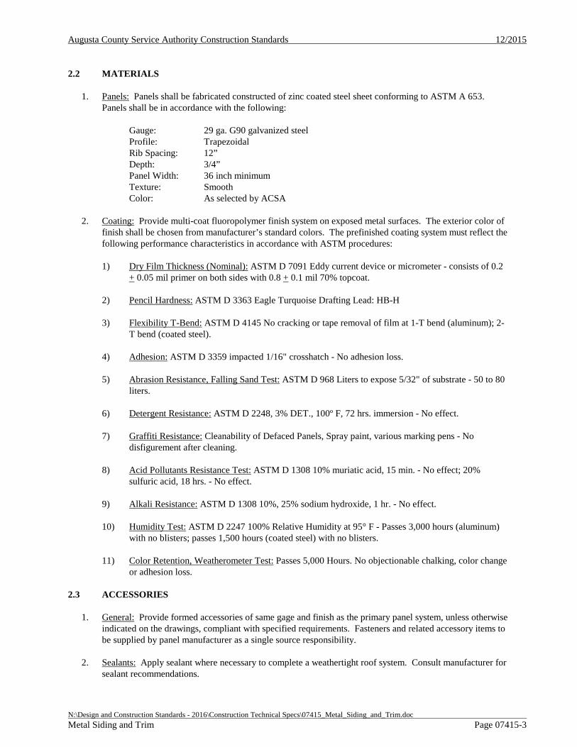
Augusta County Service Authority Construction Standards 12/2015
N:\Design and Construction Standards - 2016\Construction Technical Specs\07415_Metal_Siding_and_Trim.doc Metal Siding and Trim Page 07415-3
2.2 MATERIALS
1. Panels: Panels shall be fabricated constructed of zinc coated steel sheet conforming to ASTM A 653. Panels shall be in accordance with the following:
Gauge: 29 ga. G90 galvanized steel Profile: Trapezoidal Rib Spacing: 12” Depth: 3/4” Panel Width: 36 inch minimum Texture: Smooth Color: As selected by ACSA
2. Coating: Provide multi-coat fluoropolymer finish system on exposed metal surfaces. The exterior color of finish shall be chosen from manufacturer’s standard colors. The prefinished coating system must reflect the following performance characteristics in accordance with ASTM procedures:
1) Dry Film Thickness (Nominal): ASTM D 7091 Eddy current device or micrometer - consists of 0.2 + 0.05 mil primer on both sides with 0.8 + 0.1 mil 70% topcoat.
2) Pencil Hardness: ASTM D 3363 Eagle Turquoise Drafting Lead: HB-H
3) Flexibility T-Bend: ASTM D 4145 No cracking or tape removal of film at 1-T bend (aluminum); 2-T bend (coated steel).
4) Adhesion: ASTM D 3359 impacted 1/16" crosshatch - No adhesion loss.
5) Abrasion Resistance, Falling Sand Test: ASTM D 968 Liters to expose 5/32" of substrate - 50 to 80 liters.
6) Detergent Resistance: ASTM D 2248, 3% DET., 100º F, 72 hrs. immersion - No effect.
7) Graffiti Resistance: Cleanability of Defaced Panels, Spray paint, various marking pens - No disfigurement after cleaning.
8) Acid Pollutants Resistance Test: ASTM D 1308 10% muriatic acid, 15 min. - No effect; 20% sulfuric acid, 18 hrs. - No effect.
9) Alkali Resistance: ASTM D 1308 10%, 25% sodium hydroxide, 1 hr. - No effect.
10) Humidity Test: ASTM D 2247 100% Relative Humidity at 95° F - Passes 3,000 hours (aluminum) with no blisters; passes 1,500 hours (coated steel) with no blisters.
11) Color Retention, Weatherometer Test: Passes 5,000 Hours. No objectionable chalking, color change or adhesion loss.
2.3 ACCESSORIES
1. General: Provide formed accessories of same gage and finish as the primary panel system, unless otherwise indicated on the drawings, compliant with specified requirements. Fasteners and related accessory items to be supplied by panel manufacturer as a single source responsibility.
2. Sealants: Apply sealant where necessary to complete a weathertight roof system. Consult manufacturer for sealant recommendations.
Augusta County Service Authority Construction Standards 12/2015
N:\Design and Construction Standards - 2016\Construction Technical Specs\07415_Metal_Siding_and_Trim.doc Metal Siding and Trim Page 07415-4
3. Fasteners: As recommended by manufacturer for project conditions and panel type.
2.4 FABRICATION
1. General: Panels shall be factory fabricated with overlapping panel design. Materials are to be tension leveled during the roll forming process. Fabricate panels in one piece without transverse seams. Form all components true to shape, accurate in size, square and free from distortion or defects. Cut panels to precise lengths indicated on approved shop drawings. Factory-fabricate trim and flashing components in minimum 12 foot (3.65 mm) lengths, with allowance for thermal movement in joint design.
PART 3 EXECUTION
3.1 INSTALLATION:
1. General: Install metal panels and accessories in strict accordance with manufacturer's instructions, shop drawings, and applicable codes. Entire system shall be installed plumb, level, and true to line.
2. Panel Placement: Fasten panels to structural supports with fasteners provided by the manufacturer. Fully interlock panels with adjacent panels; apply sealants as recommended by panel manufacturer to achieve weathertight installation.
3. Flashing and Trim: Comply with performance requirements, manufacturer's written installation instructions, and the SMACNA "Architectural Sheet Metal Manual." Provide concealed fasteners where possible, and install units to true level. Install work with laps, joints, and seams that will be permanently watertight.
4. Protection: Protect surfaces from coming in contact with cementitious materials and dissimilar metals with a neutral coating such as bituminous paint. Care should be taken during handling of panels to prevent bending, twisting, abrasion, scratching, denting, etc. Do not allow shavings, metal dust, or chips to fall on panels.
END OF SECTION

Augusta County Service Authority Construction Standards 12/2015
N:\Design and Construction Standards - 2016\Construction Technical Specs\07461_Fiber_Cement_Siding_and_Trim.doc Fiber Cement Siding and Trim Page 07461-1
SECTION 07461 – FIBER CEMENT SIDING AND TRIM
PART 1 GENERAL
1.1 DESCRIPTION
1. Work Included: Furnish all material, labor and equipment required for installation of siding and trim.
2. Related Sections: Additional Sections of the Documents which are referenced in this Section include:
a. Section 01330 - Submittal Procedures
b. Section 01610 - Delivery, Storage, and Handling
1.2 SUBMITTALS
1. General: Shall be in accordance with Section 01330 - Submittals Procedures. Provide product and color samples.
1.3 DELIVERY, STORAGE AND HANDLING
1. General: Shall be in accordance with Section 01610 - Delivery, Storage, and Handling.
PART 2 PRODUCTS
2.1 MANUFACTURERS
1. General: Fiber cement siding, trim, and accessory materials shall be manufactured by James Hardie Building Products, Inc., or approved equal.
2.2 SIDING, TRIM, AND SOFFIT
1. General: HardiePlank HZ5 lap siding, HardiPanel HZ5 vertical siding, HardieSoffit HZ5 panels and HardieShingle HZ5 siding shall comply with the following standards:
a. ASTM C 1186 Type A Grade II.
b. ASTM E 136 as a noncombustible material.
c. ASTM E 84 Flame Spread Index = 0, Smoke Developed Index = 5.
d. CAL-FIRE, Fire Engineering Division Building Materials Listing - Wildland Urban Interface (WUI) Listed Product.
e. National Evaluation Report No. NER 405 (BOCA, ICBO, SBCCI, IBC, IRC).
f. US Department of Housing and Urban Development Materials Release 1263d.
2. Fasteners: Material Fasteners shall be as follows:
a. Insulated Concrete Form Ribs – Self drilling, corrosion resistant ribbed buglehead screw
b. Wood Framing – Corrosion resistant nails
3. Finishes: Products shall be supplied with factory applied universal primer.
Augusta County Service Authority Construction Standards 12/2015
N:\Design and Construction Standards - 2016\Construction Technical Specs\07461_Fiber_Cement_Siding_and_Trim.doc Fiber Cement Siding and Trim Page 07461-2
PART 3 EXECUTION
3.1 INSTALLATION
1. General: Installation shall be done in accordance with the instructions supplied by the manufacturer.
2. Preparation: Surface shall be thoroughly cleaned prior to installation. Water resistive barrier shall be applied of all wood and other appropriate surfaces. Flashing shall be installed at all openings.
3. Installation: Installation of siding, trim, and soffit shall be in strict accordance with manufacturer’s recommendations for specific materials. All gaps shall be sealed with paintable caulk.
END OF SECTION
Augusta County Service Authority Construction Standards 4/6/15
N:\Design and Construction Standards - 2016\Construction Technical Specs\07600_Gutter_Flashing_Sheet_Metal.doc Flashing and Sheet Metal Page 07600-1
SECTION 07600 – GUTTER, FLASHING, AND SHEET METAL
PART 1 GENERAL
1.1 DESCRIPTION
1. Work Included: Furnish all material, labor and equipment required for installation of window, door and roof flashing, soffit and roof vents, and gutters and downspouts.
2. Related Sections: Additional Sections of the Documents which are referenced in this Section include:
a. Section 01610 - Delivery, Storage, and Handling
1.2 DELIVERY, STORAGE AND HANDLING
1. General: Comply with the provisions of Section 01610 - Delivery, Storage, and Handling.
PART 2 PRODUCTS
2.1 FLASHING
1. General: Flashing shall be shop or field formed aluminum.
2.2 GUTTERS AND DOWNSPOUTS
1. General: Provide .025 inch aluminum gutters and downspouts where shown on the plans. All outlets shall have aluminum wire strainers. Gutter and spouts shall be prefinished with 5 inch rectangular gutter sections and 3 inch rectangular downspouts. Gutter and dounspout color shall be coordinated with the ACSA Representative.
2. Downspouts: Turn downspouts out at the bottom and provide flagstone or concrete splash-blocks unless otherwise indicated on the plans.
PART 3 EXECUTION
3.1 INSTALLATION
1. General: Materials described in this section shall be installed as shown on the plans and as recommended by the manufacturer.
2. Support: Downspouts to be secured to walls with wide bands at top and bottom. Hangers shall support downspouts at a minimum interval of 6 feet with gutter screws. Turn downspouts out at the bottom and provide flagstone or concrete splash blocks unless otherwise indicated on the plans.
END OF SECTION
Augusta County Service Authority Construction Standards 12/2015
N:\Design and Construction Standards - 2016\Construction Technical Specs\08100_Steel_Doors_and_Frames.doc Steel Doors And Frames Page 08100 - 1
SECTION 08100 – STEEL DOORS AND FRAMES
PART 1 GENERAL
1.1 DESCRIPTION
1. Work Included: Provide steel doors, complete in place with finish hardware installed, where shown on the plans, as specified herein, and as needed for a complete and proper installation.
1.2 SUBMITTALS
1. Comply with pertinent provisions of Section 01330 - Submittal Procedures.
2. Color Selection: Door colors shall be as selected by the ACSA from color charts provided by the Contractor.
1.3 DELIVERY, STORAGE, AND HANDLING
1. Comply with pertinent provisions of Section 01610 - Delivery, Storage, and Handling and with manufacturer’s recommendations.
2. Steel Door Storage: Store doors and frames at building site under cover. Avoid use of non-vented plastic or canvas shelters which can create humidity chamber. If cardboard becomes wet, remove carton immediately. Provide 1/4 inch spaces between stacked doors to promote air circulation.
1.4 QUALITY ASSURANCE
1. Comply with governing codes and regulations. Provide products of acceptable manufacturers which have been in satisfactory use in similar service for three years. Use experienced installers.
PART 2 PRODUCTS
2.1 STEEL DOORS
1. General: Provide steel doors and frames of the dimensions as shown on the plans that comply with SDI 100 and ASTM E 152. Exterior doors shall be 1 3/4 inches thick, and interior doors shall be 1 3/8 inches thick.
2. Face: Shall be minimum 18 gauge cold-rolled steel sheets completely flushed and seamless comply with ASTM A 569 and ASTM A 568.
3. Core: Interior doors shall be hollow core. Exterior doors shall be insulated.
4. Windows: Where indicated on the Drawings, doors shall be furnished with windows to allow visual inspection of areas.
5. Frames: Shall be fabricated of minimum 16 gauge, cold-rolled furniture steel complying with ASTM A 366 and ASTM A 568 or hot-rolled steel complying with ASTM A 569 and ASTM A 568.
6. Supports and Anchors: Shall be fabricated of not less than 18 gauge galvanized sheet steel.
Augusta County Service Authority Construction Standards 12/2015
N:\Design and Construction Standards - 2016\Construction Technical Specs\08100_Steel_Doors_and_Frames.doc Steel Doors And Frames Page 08100 - 2
7. Primer: Shall be rust-inhibitive enamel or paint as specified by ANSI A 224.1.
8. Finish: Shall be manufacturer's standard baking epoxy or enamel paint.
9. Hardware: Door hardware shall be as specified in Section 08700 - Door Hardware.
2.2 OTHER MATERIALS
1. General: Provide other materials, not specifically described, but required for a complete and proper installation, as selected by the Contractor subject to the approval of the ACSA Representative.
2. Caulking: All openings around doors shall be caulked with a silicone caulk of a color that will blend with surrounding surfaces. Joints shall be wide enough to permit the caulking to penetrate but not wide enough to necessitate backup.
PART 3 EXECUTION
3.1 METAL FRAME AND DOOR INSTALLATION
1. General: Installation of metal frames and doors shall be done in accordance with final shop plans, manufacturer's data, as specified in this Section, and at locations shown on the plans.
2. Tolerances: Metal doors shall be installed accurately in frames within clearances specified in SDI 100.
3. Prime Coat Touch-up: Immediately after erection, any rusted or damaged areas of prime coat shall be sand smoothed and primer touched-up.
4. Protection Removal: Immediately prior to final inspection, all protective plastic wrappings shall be removed.
5. Final Adjustments: Check and re-adjust operating finish hardware items, leaving steel doors and frames undamaged and in complete and proper operating condition.
END OF SECTION
Augusta County Service Authority Construction Standards 12/2015
N:\Design and Construction Standards - 2016\Construction Technical Specs\08700_Finish_Hardware.doc Finish Hardware Page 08700 - 1
SECTION 08700 – FINISH HARDWARE
PART 1 GENERAL
1.1 DESCRIPTION
1. Work Included: Provide finish hardware for swinging doors.
1.2 SUBMITTALS
1. Comply with pertinent provisions of Section 01330 - Submittal Procedures.
2. Submit product data, cut sheets, and hardware schedule for use based on the requirements of the Drawings and Specifications.
1.3 DELIVERY, STORAGE, AND HANDLING
1. Comply with pertinent provisions of Section 01610 - Delivery, Storage, and Handling and with manufacturer’s recommendations.
1.4 QUALITY ASSURANCE
1. Comply with governing codes and regulations. Provide products of acceptable manufacturers which have been in satisfactory use in similar service for three years. Use experienced installers.
PART 2 PRODUCTS
2.1 MATERIALS
1. Hinges, butts and pivots: Full-mortise, 5 knuckle ball-bearing type with nonremovable pins at exterior doors; Stanley or approved equal.
2. Locksets and latchsets: Each door shall be provided with a plain keyless latch set and cylinder deadlock of standard product used by the ACSA.
3. Panic Bars and Locksets: Doors shall be provided with panic bars for emergency exit. Cylinder deadlock shall be provided and installed by the CONTRACTOR. Deadlocks shall be keyed to match existing keys presently used by the ACSA.
4. Closers:
a. Low frequency doors: LCN 4030/4130 series or approved equal
b. High frequency doors (fire-labeled doors, toilet room doors, entry doors): LCN 4010/4110 series or approved equal.
5. Door Trim: Kickplates, armor plate, plastic plates; Brookline or approved equal.
6. Stops: Ives or approved equal.
7. Weatherstripping and Thresholds: ADA Compliant; Reese or approved equal.
Augusta County Service Authority Construction Standards 12/2015
N:\Design and Construction Standards - 2016\Construction Technical Specs\08700_Finish_Hardware.doc Finish Hardware Page 08700 - 2
PART 3 EXECUTION
3.1 INSTALLATION
1. Follow guidelines of DHI "Recommended Locations for Builder's Hardware for Standard Steel Doors and Frames" and hardware manufacturers' instructions.
2. Install materials and systems in accordance with manufacturer's instructions and approved submittals. Install materials and systems in proper relation with adjacent construction and with uniform appearance. Coordinate with work of other sections.
3. Adjust operation, clean and protect.
END OF SECTION
Augusta County Service Authority Construction Standards 12/2015
N:\Design and Construction Standards - 2016\Construction Technical Specs\09910_Exterior_Painting.doc Exterior Painting Page 09910 - 1
SECTION 09910 – EXTERIOR PAINTING
PART 1 GENERAL
1.1 DESCRIPTION
1 Work Included: Furnish and install all materials, equipment and labor required for the paint, finishes as shown on the plans and as specified hereunder.
2. Related Sections: Additional Sections of the Documents which are referenced in this Section include:
a. Section 01330 – Submittal Procedures
b. Section 01610 – Delivery, Storage, and Handling
c. Section 07210 – Building Insulation
1.2 SUBMITTALS
1. Comply with pertinent provisions of Section 01330 – “Submittal Procedures”.
2. Color Selection: Paint colors shall be as selected by the ACSA from color charts provided by the Contractor. The Contractor shall submit manufacturer's specifications, product data sheets and application recommendations to the Engineer for review along with shop plans.
1.3 DELIVERY, STORAGE, AND HANDLING
1. Comply with pertinent provisions of Section 01610 – “Delivery, Storage, and Handling” and with manufacturer’s recommendations.
2. Adhesive, paint, and sealer shall be stored in dry area and protected against freezing at all times.
1.4 QUALITY ASSURANCE
1. To insure compatibility, all paints and primers used for a specific task shall be provided by a single manufacturer. In the event that a manufacturer cannot supply a specified finish or system, a letter of certification shall be required to be submitted by the manufacturer stating that the system supplied is compatible with the adjacent finishes. The Contractor shall have available on site such gages, thermometers and other devices necessary to insure that application of finishes is in conformance with the manufacturer’s recommendations.
PART 2 PRODUCTS
2.1 PRIMER
1. Exterior Architectural Metals: Primer shall be a general purpose primer with a superior wetting and purpose primer with a superior wetting and penetrating properties applied as a single coat with a minimum 3 mil dry thickness. Material shall be similar to Carboline "Carboline II" or approved equal. Coating shall be according to the manufacturer product data sheet.
Augusta County Service Authority Construction Standards 12/2015
N:\Design and Construction Standards - 2016\Construction Technical Specs\09910_Exterior_Painting.doc Exterior Painting Page 09910 - 2
2.2 PAINT
1. Exterior Fiber Cement Siding and Trim: Siding and trim shall be painted with a semi-gloss acrylic latex applied at the rate to provide a minimum total of 4 mils dry thickness, or as indicated by manufacturer recommendations.
2. Exterior Architectural Metals: Finish coat shall consist of two coats of a high build epoxy applied at a rate to provide minimum of 4 mils dry film thickness. Finish coat shall be Carboline "191 HB" or approved equal.
3. Exterior Foundation: Refer to Section 07210 – Building Insulation.
PART 3 EXECUTION
3.1 PRIMING
1. General: All surfaces before receiving primer shall be prepared in accordance with the manufacturer's recommendations. Aluminum, stainless steel, bronze and plastic shall not be painted.
3.2 SURFACE PREPARATION
1. General: Woodwork finishes shall be sanded between coats. Metals shall be dry, clean and free from mill scale rust, grease and oil. After primer coat is dry, all visible suction spots shall be touched up before applying succeeding coats.
3.3 PAINTING
1. General: Contractor shall apply all paint in accordance with the manufacturer's recommendations. The Contractor shall provide protection at all times during application in strict conformance with the manufacturer's recommendations.
END OF SECTION
Augusta County Service Authority Construction Standards 12/2015
N:\Design and Construction Standards - 2016\Construction Technical Specs\09920_Interior_Painting.doc Interior Painting Page 09920 - 1
SECTION 09920 – INTERIOR PAINTING
PART 1 GENERAL
1.1 DESCRIPTION
1. Work Included: Furnish and install all materials, equipment and labor required for the paint, finishes as shown on the plans and as specified hereunder.
1.2 SUBMITTALS
1. Comply with pertinent provisions of Section 01330 – “Submittal Procedures”.
2. Color Selection: Paint colors shall be as selected by the ACSA from color charts provided by the Contractor. The Contractor shall submit manufacturer's specifications, product data sheets and application recommendations to the Engineer for review along with shop plans.
1.3 DELIVERY, STORAGE, AND HANDLING
1. Comply with pertinent provisions of Section 01610 – “Delivery, Storage, and Handling” and with manufacturer’s recommendations.
2. Adhesive, paint, and sealer shall be stored in dry area and protected against freezing at all times.
1.4 QUALITY ASSURANCE
1. To insure compatibility, all paints and primers used for a specific task shall be provided by a single manufacturer. In the event that a manufacturer cannot supply a specified finish or system, a letter of certification shall be required to be submitted by the manufacturer stating that the system supplied is compatible with the adjacent finishes. The Contractor shall have available on site such gages, thermometers and other devices necessary to insure that application of finishes is in conformance with the manufacturer’s recommendations.
PART 2 PRODUCTS
2.1 PRIMER
1. General: All material shall be suitable for interior applications.
2. Interior Architectural Metals, Equipment, and Piping: Primer shall be a general purpose primer with a superior wetting and penetrating properties applied as a single coat with a minimum 3 mil dry thickness. Material shall be similar to Carboline "Carboline II" or approved equal.
3. Concrete Masonry Units: The prime coat shall be heavy-bodied highly pigmented product for filling open textured block surfaces, applied at not to exceed 100 square feet per gallon, and similar to Pennsbury “PVA Block Filler 17-W-3” or approved equal.
4. Interior Wood: Primer shall be a high build alkyd enamel undercoat applied with 1.6 mil dry thickness. Material shall be similar to O'Brien "220-07 Enamel Undercoat" or approved equal.
Augusta County Service Authority Construction Standards 12/2015
N:\Design and Construction Standards - 2016\Construction Technical Specs\09920_Interior_Painting.doc Interior Painting Page 09920 - 2
2.2 PAINT
1. Wood Surfaces: Interior wood and surfaces shall receive two coats of an epoxy applied at a rate to provide a total of 4 mils dry film thickness. Paint shall be Pennsbury "Series 51", Koppers "Glamorglaze 200 Epoxy", Carboline "No. 193 Gloss", Mobil "Val-Chem 84", or approved equal.
2. Interior Architectural Metals, Equipment and Piping: Finish coat shall consist of two coats of a high build epoxy applied at a rate to provide a minimum of 4 mils dry film thickness. Finish coat shall be Carboline “890” or approved equal.
3. Piping, Equipment, and Miscellaneous Metals: Finish coat shall consist of two coats of a high build epoxy applied at a rate to provide a minimum of 4 mils dry film thickness. Finish coat shall be Carboline "191 HB", Koppers "Glamorglaze 200", an intermediate and finish coat of Mobil "Val-Chem 89" followed by "Val-Chem 84" or approved equal.
4. Submerged Metals, Piping, and Equipment: Ductile iron piping within tank coated with an NSF 61 approved two part epoxy coating of Carbogard 891, Tnemec Pota-Pox, or equal, with a final dry film thickness of 12-14 mils.
PART 3 EXECUTION
3.1 SURFACE PREPARATION
1. General: Interior woodwork and gypsum finishes shall be sanded between coats. Concrete surfaces shall be wire brush cleaned. Metals shall be dry, clean and free from mill scale, rust, grease and oil. After primer-sealer coat is dry, all visible suction spots shall be touched up before applying succeeding coats.
2. Surfaces shall be prepared in accordance with the manufacturer's recommendations and shall be generally free of oil, grease, stains, mill scale and loose rust.
3.2 PRIMING
1. General: All surfaces before receiving primer shall be prepared and primed in accordance with the manufacturer's recommendations. All equipment, piping, and miscellaneous metals shall receive a prime coat or touch-up coat of rust penetrating primer prior to finish coats. Aluminum, stainless steel, bronze, plastic and equipment nameplates shall not be painted.
3.3 PAINTING
1. General: Apply all paint in accordance with the manufacturer's recommendations. Provide protection at all times during application in strict conformance with the manufacturer's recommendations.
END OF SECTION
Augusta County Service Authority Construction Standards 12/2015
N:\Design And Construction Standards - 2016\Construction Technical Specs\11315_Wastewater_Pump_Station.Doc Wastewater Pump Stations Page 11315-1
SECTION 11315 – WASTEWATER PUMP STATIONS
PART 1 GENERAL
1.1 REFERENCES
1. General: The work shall comply with the most recent standards or tentative standards as published in this specification using the associated abbreviation(s).
2. American Society for Testing and Materials (ASTM):
a. A 48 Standard Specification for Gray Iron Castings
b. A 536 Standard Specification for Ductile Iron Castings
3. American National Standards Institute (ANSI)/National Fire Protection Association (NFPA):
a. 70 National Electrical Code
1.2 GENERAL REQUIREMENTS
1. Pumps: All pumps to be installed by the CONTRACTOR shall be supplied by a single manufacturer in accordance with ACSA Approved Products List.
2. Operation and Maintenance (O&M) Manuals: Shall be provided in accordance with Section 01110-1.12.3.3c in accordance with the Sewage Collection and Treatment Regulations.
1.3 QUALITY ASSURANCE
1. Start Up Service: The CONTRACTOR shall provide and coordinate the services of the equipment manufacturer's field service technician for a minimum period of 2 trips and 2 days for each piece of equipment. This service shall be for the purposes of check-out, initial start-up, certification, verification of actual pumping rate, verification of pressure settings, valve operation, and instruction of the Authority’s personnel. A written report covering technician's findings and installation approval shall be submitted to the Authority covering all inspections and outline in detail any deficiencies noted. The CONTRACTOR shall provide the Authority within 10 days of start-up, a letter from the manufacturer of each item of equipment stating that the equipment has been properly installed and started and that nothing has been done that may violate the warranty.
2. Factory Tests: All pumps shall be tested by the manufacturer or a nationally recognized testing agency in compliance with Hydraulic Institute Standards. Certified test results shall be submitted to the Authority’s Representative at or before delivery.
3. Performance Test Reports: Upon completion and testing of the installed system, test reports shall be submitted in booklet form for incorporation into the O&M Manual showing all field tests performed to adjust each component and all field tests performed to prove compliance with the specified performance criteria.
4. Pump Characteristics Curves: Pump characteristic curves showing capacity in gpm, head, efficiency and pumping horsepower should be submitted with the shop plans and contained in the O&M Manual.
5. Spare Parts and Lubrication: CONTRACTOR shall provide the Authority with an adequate supply of spare parts and lubricants to last the duration of the 1 year warranty period as recommended by the equipment manufacturer. An adequate supply shall be defined as the
Augusta County Service Authority Construction Standards 12/2015
N:\Design And Construction Standards - 2016\Construction Technical Specs\11315_Wastewater_Pump_Station.Doc Wastewater Pump Stations Page 11315-2
quantity, type, and grade recommended by the manufacturers who will provide the equipment contained in this section. Any special lubricants that may be required during the equipment break-in period shall also be provided.
6. Name Plates: Pumps and motors shall have the manufacturer's name, address, type or style, model or serial number, impeller size and type, and catalog number on a plate secured to the item of equipment.
7. Verification of Dimensions: The CONTRACTOR shall become familiar with all details of the work, verify all dimensions in the field, and shall advise the Authority’s Representative of any discrepancy before performing the work.
8. Warranty: All pumps provided to the Authority shall carry a minimum 1 year warranty. Warranty on any pumping equipment shall begin at the date of startup (not delivery) unless otherwise accepted by the Service Authority Engineering Department due to extenuating circumstances regarding installation timing.
9. Pump Station Start Up:
a. Valves in proper positions
b. Correct pump rotation
c. Air relief valves working properly
d. Secure wiring properly
e. Pump performance (AMP Draw, GPM, Etc.)
f. Test controls (Alarms, Floats, HOA Switches, etc.)
g. Test against flow meter.
h. Compare performance to pump curve
i. Check for good pump seating
j. Test back-up systems (generator, bypasses, etc.)
k. Pumps need to be accessible for maintenance (cranes, beams for chain hoists, etc.)
l. Security of vaults, controls, etc. (pad lock keyed to ACSA standard key)
m. Verify sloping in bottom of wet well
n. Verify anchoring to prevent floating
o. ACSA needs copies of building inspections final
p. DEQ acceptance and CTO
q. As Builts required
r. Lot dedication
Augusta County Service Authority Construction Standards 12/2015
N:\Design And Construction Standards - 2016\Construction Technical Specs\11315_Wastewater_Pump_Station.Doc Wastewater Pump Stations Page 11315-3
s. Where permanent entrance will be.
t. Update O&M.
PART 2 PRODUCTS
2.1 PUMP STATION EQUIPMENT
1. General: Products for wastewater pump stations shall be selected and designed specific to individual projects. The designer shall prepare an operational description and construction specifications for individual projects and shall submit them for approval in accordance with the Design and Construction Standards. The approved specifications, in addition to the Design and Construction Standards, shall be used by the CONTRACTOR during the construction phase.
2. Pump station products shall be in accordance with the Authority’s Approved Products List as applicable. Products not listed shall be approved at the discretion of the Authority.
PART 3 EXECUTION
3.1 INSTALLATION
1. General: The CONTRACTOR shall install all equipment in strict accordance with the manufacturer's recommendations. The CONTRACTOR shall supply all equipment and accessories not specifically provided by the manufacturer but required for satisfactory installation and operation. All anchor bolts shall be plated steel and placement shall be in accordance with the design engineer’s drawings and specifications. All other miscellaneous fasteners shall be stainless steel. All bolts shall be of ample size and grade for the purpose intended.
2. Startup: The CONTRACTOR shall coordinate startup services of the equipment manufacturer’s field service technician with the Authority’s Representative.
END OF SECTION
Augusta County Service Authority Construction Standards 12/2015
N:\Design and Construction Standards - 2016\Construction Technical Specs\13200_Ground_Storage_Tank_Potable_Water.doc Generic Ground Storage Tank – Potable Water Page 13200 - 1
SECTION 13200 – GENERIC GROUND STORAGE TANK – POTABLE WATER
PART 1 GENERAL
1.1 DESCRIPTION
1. Work Included: Furnish all equipment, material, labor and appurtenances necessary for the design, manufacture, delivery, erection, painting and testing of an above ground water storage tank
1.2 REFERENCES
1. General: The Work shall comply with the most recent or tentative standards as published at the time of construction and as listed in the Design and Design and Construction Standards.
2. Related Sections: Additional Sections of the Documents which are referenced in this Section Include:
1) Section 01110 – General Requirements
2) Section 02085 – Valves and Cocks
3) Section 02200 – Site Construction for Pump Stations
4) Section 16100 – Electrical Requirements for Pump Stations
3. American Society for Testing and Materials (ASTM):
1) A 6/A 6M Standard Specification for General Requirements for Rolled Structural Steel Bars, Plates, Shapes, and Sheet Piling
2) A 36/A 36M Standard Specification for Carbon Structural Steel
3) A 185 Standard Specification for Steel Welded Wire Fabric, Plain, for Concrete Reinforcement
4) A 193/193M Standard Specification for Alloy-Steel and stainless Steel Bolting Materials for High-Temperature Service
5) A 283/A 283M Standard Specification for Low and Intermediate Tensile Strength Carbon Steel Plates
6) A 648 Standard Specification for Steel Wire, Hand Drawn for Concrete Pipe
7) A 1008/A 1008M Standard Specification for Steel, Sheet, Cold-Rolled, Carbon, Structural, High-Strength Low-Alloy and High-Strength Low- Alloy with Improved Formability
8) C 652 Disinfection of Water Storage Facilities
9) C 881 Standard Specification for Epoxy Resin-Base Bonding Systems for Concrete
Augusta County Service Authority Construction Standards 12/2015
N:\Design and Construction Standards - 2016\Construction Technical Specs\13200_Ground_Storage_Tank_Potable_Water.doc Generic Ground Storage Tank – Potable Water Page 13200 - 2
4. American National Standards Institute (ANSI)/American Water Works Association (AWWA):
1) C 652 Standard for Disinfection of Water Storage Facilities
2) D 103 Standard for Factory-Coated Bolted Steel Tanks for Water Storage
3) D 110 Standard for Wire- and Strand-Wound Circular Prestressed Concrete Water Tanks
5. American Concrete Institute (ACI):
1) 506 Guide to Shotcrete
2) 506 3R Guide to Certification of Shotcrete Nozzlement
6. Building Officials Code of America (BOCA):
1) Wind and Earthquake Loading Requirements
7. American National Standards Institute / National Sanitation Foundation (ANSI/NSF):
1) Std. 61 Drinking Water System Components-Health Effects
1.3 QUALITY CONTROL SUBMITTALS
1. General: The CONTRACTOR shall be a specialist in the design, fabrication and erection of tanks, and shall have built in its own name (5) comparable tanks now giving satisfactory service. The Contractor shall provide the Authority with written documentation that the tank provided for installation on this project is approved by all pertinent local, state and federal agencies.
2. Qualifications: The tank shall be erected by the manufacturer or by a licensed agent of the tank manufacturer. Upon request, crews must be able to document three tanks of comparable size and design they have constructed.
3. Submittals: The tank construction company shall submit six (6) copies of properly identified and neatly bound complete design calculations, sketches and illustrations along with six (6) sets of detailed working drawings for the tank. All design data shall be listed and referenced to the chapter, section and paragraph of applicable codes noted. Structural calculations for the tank and foundation shall be reviewed, signed and sealed by a currently registered Professional Engineer in the Commonwealth of Virginia. Additional submittal requirements are identified in Section 01110.
1.4 SYSTEM DESCRIPTION
1. General: The storage tanks shall be of the prestressed concrete or bolted glass-fused-to-steel type. The tank diameter, volume, and elevation of the high and low water levels shall be shown on design plans approved by the Augusta County Service Authority (Authority). A separate tank valve shed shall be located on site to house tank control valving, instrumentation, and auxiliary equipment.
2. Tank Design: Design of the tank shall be in accordance with the latest revision of AWWA Standards referenced in this section. The tank shall be designed to withstand wind and earthquake loadings according to AWWA and BOCA requirements. Earthquake design shall be made according to the ANSI/AWWA D 103 and 110, Pseudodynamic approach. Shop drawings from the tank manufacturer shall be certified by
Augusta County Service Authority Construction Standards 12/2015
N:\Design and Construction Standards - 2016\Construction Technical Specs\13200_Ground_Storage_Tank_Potable_Water.doc Generic Ground Storage Tank – Potable Water Page 13200 - 3
a Virginia registered Professional Engineer. The cost of any modification of the tank foundation required by the specific tank design shall be borne by the CONTRACTOR. The following design parameters shall apply, and the structure shall safely withstand the following loads acting separately or in combination.
1) Weight of Structure and all accessories.
2) Weight of Water in tank
3) Wind Loading: 100 MPH in any direction
4) Seismic Zone: 1 per ANSI/AWWA D103 and 110
5) Snow load: Minimum of 25 PSF as specified in ANSI/AWWA D103 and 110
3. Inlet & Outlet Piping Design: Tank shall include a separate inlet and outlet piping, with entry and exit points located generally on opposite sides of the tank to promote mixing. A separate tank drain shall be provided to daylight with isolation gate valve. The tank slab shall slope to the drain inlet, which shall be flush with the interior tank slab surface. A minimum ¾” line shall be connected from the drain line to the valve shed for tank level sensing. Pipes shall enter tank upwards through the slab as close as possible to inlet and outlet locations. Check valves shall be provided in a separate tank valve shed to ensure one way flow though dedicated inlet and outlet pipes. Centerline of all piping outside tank and within valve shed shall be at or below tank base elevation to maintain 100% effective storage volume.
1.5 DELIVERY, STORAGE, AND HANDLING
1. General: Comply with provisions in Section 01110.
1.6 SITE PREPARATION
1. General: All site work shall be performed in accordance with Sections 02200.
PART 2 PRODUCTS
2.1 GENERAL TANK COMPONENTS
1. General: Tanks may be prestressed concrete or bolted glass-fused-to-steel designed and constructed in accordance with ANSI/AWWA D 103 or ANSI/AWWA D 110.
2. Bolts, Anchor Bolts, and Rods: Bolts and anchor bolts shall be stainless steel and conform to the latest revision of ASTM A 193/193M. Rods shall be open-hearth or electric steel conforming to the latest revisions of ASTM A 36. If bolted tanks are used, all bolt heads shall be coated with an approved corrosion resistant material similar to EPDM. Bolts shall be rust proof treated prior to erection and be installed with the appropriate gasket and sealant as required by ANSI/AWWA D 103.
3. Piping: All internal piping shall be stainless steel, including pipe supports. External piping may be ductile iron or as approved by the Authority. Piping for tank shall be in accordance with Section 02080.
4. Shell Manhole: The CONTRACTOR shall provide 24 inch diameter shell manholes, furnished with hinged and bolted covers located in the first ring of the tank shell. Concrete and bolted steel tanks shall require a minimum of one shell manhole.
Augusta County Service Authority Construction Standards 12/2015
N:\Design and Construction Standards - 2016\Construction Technical Specs\13200_Ground_Storage_Tank_Potable_Water.doc Generic Ground Storage Tank – Potable Water Page 13200 - 4
5. Pipe Connections: The CONTRACTOR shall be responsible for making all pipe connections indicated on the drawings.
6. Overflow: The tank shall be equipped with an overflow suitably anchored to the shell of the tank with a reducer at the inlet, and designed for a minimum 1.5 times the calculated maximum tank fill rate. The elevation of the overflow shall be set to provide the specified tank capacity above the outlet. Overflow outlet shall be fitted with a flexible duckbill check valve and discharge to a drop inlet near the tank wall. Overflow shall be located so that it is visible from the tank site entrance gate.
7. Visual Level indicator: A float-operated gage level-indicator will be provided and installed at the tank. This indicator will consist of stainless steel float, aluminum sheave elbow with stainless steel trim and teflon bearings, stainless steel cable and guides, and all necessary clamps, guides, and fasteners to make a complete and operable system. Install target board painted per exterior specifications and will be marked in foot increments and numbered every two feet. Markings and numbers will be easily visible from outside of perimeter fence. Level indicator shall be located so that it is visible from the tank site entrance gate.
8. Tank Ladders: The CONTRACTOR shall furnish a tank ladder on the outside of the tank shell at the location indicated on the drawings. The ladder shall be equipped with a cage and a safety climb device as approved by ACSA and meeting OSHA requirements. An OSHA approved suitable locked guard or other device similar to “Ladder Guard” as manufactured by the Leary Construction Company shall be provided on the outside ladder to prevent unauthorized access. Ladders shall be aluminum or stainless steel.
9. Roof Hatch: The CONTRACTOR shall furnish a roof hatch located as shown on the drawings. The hatch shall be equipped with hinges and hasps for locking. The opening shall have a curb at least 4 inches high, and the cover shall overlap the curb by two inches. The roof hatch shall be located to allow viewing of and access to the inlet/outlet piping, overflow, and drain.
10. Vent: The CONTRACTOR shall furnish a suitable vent with the capacity to pass air so that at the maximum possible rate of water either entering or leaving the tank, dangerous pressures will not develop. Designer shall identify and confirm the maximum rate with the Authority. The overflow pipe shall not be considered a tank vent. The vent shall be a freeze proof design and constructed with No. 4 mesh 8 gauge stainless steel screen as to prevent the ingress of birds or animals. A walkway with safety handrail and floor tread shall be provided on the tank roof for access to the vent from the tank ladder.
11. Floor: Tank floor shall be of concrete construction, and shall be monolithic to the concrete walls where prestressed concrete tanks are provided. The slab shall slope to the tank drain location. Where glass lined steel tank is constructed, a sealer shall be applied around the base of the reservoir to prevent water from running back under the bottom of the tank on the exterior. The base sealant shall be a two component, non-sag, elastomeric, polyurethane sealant formulated to remain flexible under atmospheric extremes. Base sealant shall be Sikaflex-2c NS, Saunders #2000 Sealant, Old North Mfg., Inc. ONA SEAL or approved equal.
12. Gaskets/Interior Sealants/Coatings/Sealants: Gaskets, Sealants and Coatings shall be NSF 61 approved and shall be in accordance with applicable ANSI/AWWA standards.
13. Identification Plate: A manufacturer’s identification plate shall be provided and shall list the tank serial number, diameter, height, minimum capacity, intended storage use, date of installation, and bear the NSF certification mark. The identification plate shall be affixed to the tank exterior sidewall at a location approximately 5 feet from grade elevation in a position of unobstructed view.
14. Tank Foundation: The tank foundation shall be designed and constructed in accordance with the applicable ANSI/AWWA standard and the Subsurface Exploration & Geotechnical Analysis Report. Tank foundation shall be constructed on a minimum of 12” thickness of #57 stone, with a minimum of 24” of soil depth
Augusta County Service Authority Construction Standards 12/2015
N:\Design and Construction Standards - 2016\Construction Technical Specs\13200_Ground_Storage_Tank_Potable_Water.doc Generic Ground Storage Tank – Potable Water Page 13200 - 5
provided around the foundation for frost protection. A turndown foundation may be required to meet this requirement. Concrete work shall comply with Section 02200 and the following:
1) Reinforcing steel shall be supported to prevent direct contact with the ground. Masonry brick or plastic coated metal chairs may be used. The use of steel rods or other materials driven into the ground shall be strictly prohibited. Alternate methods of supporting reinforcing may be approved by the Authority, provided that they do not include any direct connection between uncoated reinforcing steel and ground.
2) Concrete slabs within the perimeter of the tank walls shall receive a trowel finish. Exterior concrete shall receive a broom finish.
15. Roof: Roof shall be of same material as tank walls or aluminum in accordance with AWWA Standards.
16. Signage: Signs shall be posted on the tank providing notices for Confined Spaces Entry and Fall Protection requirements. Signage location and wording shall be approved by the Authority.
2.2 PRESTRESSED CONCRETE TANKS
1. General: Prestressed concrete tanks shall be designed and constructed in accordance with ANSI/AWWA D 110.
2. Walls: Core wall design shall be in accordance with AWWA D 110 Section 3.5, and the following:
1) Design: The wire-prestressed composite wall shall be a type II wall as specified in AWWA D 110 Section 1, consisting of a shotcrete core wall encasing a steel shell diaphragm continuous the full wall height.
2) Steel Shell Diaphragm: A 26 gauge steel tank shell, complying with ASTM A 1008/1008M for Commercial Quality Cold Rolled Steel, shall be used within and throughout the core wall providing a positive waterstop. All vertical joints in the diaphragm shall be sealed watertight by epoxy injection. The sealant shall conform to the requirements of ASTM C 881, Type III, Grade 1. In all tanks designed to use a waterstop at the floor/wall joint, the steel shell diaphragm shall be epoxy bonded to the waterstop.
3. Dome Roof: Dome roof design shall be in accordance with AWWA D 110 Section 3.6. Roof shall be constructed of reinforced concrete or shotcrete, circumferentially prestressed. Dome shell reinforcement shall consist of reinforcing steel bars or welded wire fabric meeting ASTM A 185, hot galvanized. The dome shell shall be designed as a free span, spherical thin shell, with a one-tenth rise. All surfaces in the wall/dome ring girder joint shall be coated with an approved bonding epoxy. The water level in the tank shall be permitted to encroach on the dome shell no higher than the upper horizontal plane of the dome ring girder.
4. Pre-stressing Wire: Pre-stressing wire shall in be cold-drawn, high carbon wire complying with ASTM A 648 and AWWA D 110 Section 3, placed under high tension.
5. Shotcrete: Shotcrete shall be in accordance with AWWA D 110 Section 2 and 3.
Should the strengths of mortar shown by the test specimens made and tested in accordance with the above provisions fall below the values given, the Authority shall have the right to require changes in the mortar mix for the remainder of the work. Furthermore, the Authority shall have the right to require additional curing on those portions of the structure represented by the failing test specimens. In the event that such additional curing does not give the strength required, as evidenced by core and/or other tests, the Authority
Augusta County Service Authority Construction Standards 12/2015
N:\Design and Construction Standards - 2016\Construction Technical Specs\13200_Ground_Storage_Tank_Potable_Water.doc Generic Ground Storage Tank – Potable Water Page 13200 - 6
shall have the right to require strengthening or replacement of those portions of the structure which fail to develop the required strength. The CONTRACTOR shall have no claim for reimbursement for the required corrective measures.
6. Coating: Exposed exterior tank surface shall receive a concrete and masonry coating. Coating shall be Tnemec Series 156 “Enviro-Crete” or similar approved by the Authority. Coating shall be applied in accordance with manufacturer’s recommendations.
2.3 BOLTED GLASS-FUSED-TO-STEEL TANKS
1. General: Bolted steel water tanks shall be fabricated in accordance with ANSI/AWWA D 103.
2. Foundation: Foundation shall be in accordance with ANSI/AWWA D 103, Section 11.4, Type 2 or 6.
3. Exterior Base Sealant: A sealer shall be applied around the base of the reservoir to prevent water from running back under the bottom of the tank on the exterior. The base sealant shall be a two component, non-sag, elastomeric, polyurethane sealant formulated to remain flexible under atmospheric extremes. Sealant shall be applied with backer ring. Base sealant shall be Sikaflex-2c NS, Saunders #2000 Sealant, Old North Mfg., Inc. ONA SEAL or approved equal.
4. Plates: Plate material shall be open-hearth or electric furnace steel conforming to the latest revision of ASTM A 283.
5. Rolled Structural Steel: Rolled structural shapes shall conform to the minimum standards of ANSI/AWWA D 103, Section 2.5, and ASTM A 6 and ASTM A 36.
6. Coating: Wall plates shall be of glass fused to steel construction, factory prepared in accordance with ANSI/AWWA D 103 and shipped to the site ready for assembly. Coating shall be a “three coat” system similar to Aquastore VitriumTM applied on all panel surfaces, including edges. Sheet edges of sidewall and floor plates shall be mechanically rounded and flame coated with stainless steel prior to glass coating. Glass coating of the sheet edges shall be similar to the flat panel surfaces. The process shall be applied to all four sheet edges. Roof panels shall be of either glass fused to steel or aluminum construction.
2.4 AUXILLARY EQUIPMENT
1. General: A valve shed shall be constructed at the tank site to house tank control valving, instrumentation, and auxiliary equipment. The building shall be masonry construction with finish as approved by the Authority.
2. Valves: Valves shall be as specified in Section 02085.
3. Electrical: Electrical shall meet minimum requirements identified in Section 16010.
4. Level Transducer: The tank level shall be measured by a pressure transducer connected to the sensing line from the tank drain. A hose bibb shall be installed at the end of the sensing line within the valve shed for flushing. The transducer shall be of the solid state head pressure sensing type providing a 4-20 mA instrumentation signal. The transducer housing shall be fabricated of type 316 stainless steel and be suitable for connection to a threaded pipe tap. The pressure shall be transmitted by an internal oil fill to a gauge pressure type variable capacitance transducer, which converts the pressure to a directly proportional electrical signal. The power supply to the transducer shall be 24VDC supplied by the SCADA RTU. Sensor shall be installed with injection style sealing fitting to protect instrument from water intrusion and shall include isolation ball valve at pipe connection.
Augusta County Service Authority Construction Standards 12/2015
N:\Design and Construction Standards - 2016\Construction Technical Specs\13200_Ground_Storage_Tank_Potable_Water.doc Generic Ground Storage Tank – Potable Water Page 13200 - 7
5. SCADA System: SCADA system shall be in accordance with ACSA Approved Products List.
PART 3 EXECUTION
3.1 GENERAL
1. Erection: The tank shall be erected by the manufacturer or a licensed agent of the tank manufacturer.
2. Field Inspection: Field inspection of the tank may be made by a Resident Project Representative designated by the Authority. The CONTRACTOR will bear the cost of this inspection. Field inspection shall be conducted in accordance with applicable designations of ANSI/AWWA D 103 and 110. Any inspections by the Authority shall in no way relieve the CONTRACTOR of his obligation to certify that the construction is performed according to the plans and specifications.
3. Level Indicator: Install level indicator per manufacturer recommendations in a location per the contract documents as approved by the Authority.
4. Cleaning: Upon completion of construction, the tank shall be cleaned to remove dirt, construction debris, or other loose materials prior to disinfection of the structure. Only potable water shall be used to clean and rinse the tank. All equipment including pumps, hoses, brooms, brushes, and workman’s boots shall be disinfected before being used to perform the cleaning operations.
5. Testing:
1) Watertightness Testing: After the tank is completed, it shall be filled with water furnished at the site by the Authority. Authority will provide at no cost to the Contractor an adequate volume of water to fill the tank as many as two times. If additional water is required for repeat testing, CONTRACTOR maybe responsible for purchasing water from the Authority at the standard bulk rate. Any leaks that are disclosed in this test of the shell, shall be appropriately repaired. No repair work shall be done on any joints unless the water in the tank is at least 2 feet below the point being repaired.
2) Foundation Testing: Slump, air and compressive cylinder testing shall be performed by an independent laboratory approved by the Authority. A minimum of two test cylinders shall be cast and tested at 7, 14 and 28 days. All test results are to be submitted to the Authority. The CONTRACTOR shall be responsible for all costs associated with testing.
6. Tank Disinfection: After construction and repairs have been effected and painting has been completed, including recommended curing and cleaning, the tank shall be disinfected by one or a combination of the following procedures as specified in ANSI/AWWA C 652 which is summarized below.
1) Method One: The tank shall be filled to the overflow level with potable water to which enough chlorine has been added to provide an initial chlorine concentration in the full tank of not less than 10 mg/L. The full tank should stand for 24 hours. The chlorine shall be added either as calcium hypochlorite, sodium hypochlorite, or liquid chlorine as described hereafter.
a) Liquid Chlorine use. Liquid chlorine shall be introduced into the water filling the tank in such a way as to produce a uniform chlorine concentration during the entire filling operation. Portable chlorination equipment shall be carefully operated and include a liquid-chlorine cylinder, gas-flow chlorinator, chlorine ejector, safety equipment, and an appropriate solution tube to inject the high-concentration chlorine solution into the filling water. The solution tube shall be installed through a valve located on the inlet pipe and near the storage facility such that the chlorine will mix readily with the in-flowing water.
Augusta County Service Authority Construction Standards 12/2015
N:\Design and Construction Standards - 2016\Construction Technical Specs\13200_Ground_Storage_Tank_Potable_Water.doc Generic Ground Storage Tank – Potable Water Page 13200 - 8
b) Sodium Hypochlorite use. Sodium hypochlorite shall be added to the water filling the tank by means of a chemical-feed pump, or shall be hand poured into the tank which allows the in-flowing water to provide the mixing. When the chemical-feed pump is used, the concentrated chlorine solution shall be pumped through an appropriate solution tube at a rate that will provide a uniform chlorine concentration in the filling water. The solution tube shall be installed through a valve located on the inlet pipe and near the storage facility, or through an appropriate valve on the storage facility such that the chlorine will mix readily with the in-flowing water. When the sodium hypochlorite is poured into the tank, the filling of the tank shall begin immediately thereafter. The sodium hypochlorite may be poured into the tank through the cleanout or inspection manhole or through the roof manhole. Sodium hypochlorite is to be added when the water level in the tank is not more that 3 feet and not less than 1 foot in depth or as close to these depths as the manhole locations will permit.
c) Calcium Hypochlorite use. Calcium hypochlorite granules or tablets crushed to sizes not larger than ¼ inch maximum dimension may be poured or carried into the tank through the cleanout, inspection manhole, or roof manhole. The calcium hypochlorite shall be put in the tank before any water is added. The granules or tablets shall be located so the in-flowing water will ensure a current of water circulating through the calcium hypochlorite, dissolving it during the filling operation. Calcium hypochlorite shall be placed only on dry surfaces unless proper precautions for adequate ventilation and protective breathing equipment are taken.
d) After the tank has been filled with the disinfecting solution, a retention period is required. A retention period of not less than 24 hours is required. At the end of the holding period, the highly chlorinated water shall be drained to waste and the tank refilled with potable water and tested for bacteriological quality.
e) The handling of the disinfection water shall be as follows. After the holding period, the free chlorine residual shall be reduced to not more than 2 mg/L. This shall be accomplished by completely draining the storage facility and refilling it with potable water, or by a combination of additional holding time and blending with potable water. When an appropriate chlorine residual is obtained, bacteriological testing shall be performed. If satisfactory results are obtained from testing, the water may be delivered to the distribution system.
f) The environment to which the chlorinated water is to be distributed shall be inspected. If there is any likelihood that the discharged water would cause damage, a reducing agent shall be added to the chlorinated water. Federal, state, and local environmental regulations may require special provisions or permits for the discharge of highly chlorinated water. The CONTRACTOR shall contact the proper authorities prior to the disposal of highly chlorinated water. The CONTRACTOR shall drain the tank at a rate, which does not overload the downstream drainage system. The drainage rate shall be controlled to prevent erosion of natural ditches downstream from the point of discharge. Chlorinated water shall not be discharged to any water course or drainageway until it has been reduced or diluted to a level, which will result in no damage to aquatic life.
2) Method Two: The tank shall have a solution of 200 mg/L available chlorine applied directly to the surfaces of all parts of the storage facility that would be in contact with water when the storage facility is filled to the overflow elevation. The solution shall thoroughly coat all surfaces to be treated, including the inlet and outlet piping, and shall be applied to any separate drain piping such that it will have available chlorine of not less than 10 mg/L when filled with water. Overflow piping does not need to be disinfected. The chlorine solution shall be applied with either spray equipment or brushes. Any equipment used to apply the chlorine solution shall either be new or previously used only for disinfection purposes. The strong solution shall remain in contact with the tank
Augusta County Service Authority Construction Standards 12/2015
N:\Design and Construction Standards - 2016\Construction Technical Specs\13200_Ground_Storage_Tank_Potable_Water.doc Generic Ground Storage Tank – Potable Water Page 13200 - 9
surfaces for at least 30 minutes, after which potable water shall be admitted, and the drain piping purged of the 10 mg/l chlorinated water. The tank shall then be filled with potable water to the overflow level and tested for bacteriological quality. If satisfactory results are obtained from testing, the water may be delivered to the distribution system.
3) Method Three: Water and chlorine shall be added to the tank in amounts such that the solution will initially contain 50 mg/L available chlorine and will fill approximately 5 percent of the total storage volume. The solution containing 50 mg/l of chlorine shall stand in the tank for not less than 6 hours. The tank shall then be filled with potable water to the overflow level and allowed to stand for not less than 24 hours. At the end of the 24 hour period, the chlorine residual in the tank shall be at least 2 mg/L. Drain lines shall be flushed of all remaining high strength chlorine. The tank shall then be tested for bacteriological quality. If satisfactory results are obtained from testing, the water may be delivered to the distribution system.
4) Bacteriological Testing: Two or more successive samples taken at 24 hour intervals shall be required and shall indicate bacteriologically satisfactory water before the facility is released for use. All tests shall be paid for by the Contractor.
3.2 PRESTRESSED CONCRETE TANKS
1. General: The tank shall be erected by the manufacturer or a licensed agent of the tank manufacturer. Erection of the tank shall be in accordance with AWWA D 110, Section 5.
2. Shotcrete: All shotcrete shall be applied in accordance with ACI 506, under the direct supervision of experienced nozzlemen certified in accordance with the guidelines of ACI 506.3R-82.
3. Painting: Painting of the exposed exterior surfaces of the tank shall consist of a prime coat of masonry undercoat, plus two coats of exterior masonry paint. All painting shall be done in accordance with the paint manufacturer's recommendations.
3.3 BOLTED GLASS-FUSED-TO-STEEL TANK
1. Shop Fabrication: Shop fabrication shall conform to applicable designations of ANSI/AWWA D 103.
2. Erection: Erection of the tank shall be in accordance with ANSI/AWWA D 103, Section 7.
3. Interior Sealant (Bolted Floors): If a bolted plate floor is constructed, interior base sealant shall be applied around entire perimeter of floor/wall joint.
4. Testing:
1) Tank Bottom: Upon completion of the tank bottom, it shall be tested and shall be made entirely tight to the satisfaction of the ACSA’s Resident Project Representative. Testing may be done by applying vacuum to the joint using soap suds, linseed oil, or other suitable material for the detection of leaks. The magnetic particle methods may also be used for testing of the joints.
END OF SECTION
Augusta County Service Authority Construction Standards 12/2015
N:\Design And Construction Standards - 2016\Construction Technical Specs\16010_Electrical_Requirements_For_Pump_Stations.Doc Electrical Requirements for Pump Stations Page 16010-1
SECTION 16010 – ELECTRICAL REQUIREMENTS FOR PUMP STATIONS
PART 1 GENERAL
1.1 REFERENCES
1. General: The work shall comply with the most recent standards or tentative standards as published at the date of the contract and as listed in this specification using the abbreviation shown.
2. National Fire Protection Association (NFPA):
a. 70 National Electrical Code
b. 101 Life Safety Code
3. National Electrical Manufacturers' Association (NEMA):
a. 250-1979 Enclosure Description and Application
1.2 SUBMITTALS
1. General: The following shall be submitted. Materials and equipment will be approved based on the manufacturer's published data.
2. Detail Plans: Detail plans shall be submitted for approval and shall consist of a complete list of equipment and materials, including manufacturer's descriptive and technical data; catalog cuts; and any special installation instructions that may be required. Detail plans shall be submitted for all materials and equipment specified. Applicable schematic diagrams, equipment layout and anchorage shall be shown.
3. Test Reports: The label or listing of the Underwriters Laboratories, Inc. shall be submitted as evidence that the materials or equipment conform to the applicable standards of that agency.
4. Certificates of Compliance: For other than equipment and materials specified to conform to UL publications, a manufacturer's statement indicating complete compliance with the applicable Federal Specification, or standard of the ASTM, NEMA or other commercial standard, is acceptable.
1.3 QUALITY ASSURANCE
1. Standard Products: Materials and equipment shall be the standard catalog products of a UL listed manufacturer regularly engaged in the manufacture of the products that have been in satisfactory use for at least 2 years. All materials and equipment shall be in accordance with the ACSA Approved Products List.
2. U.L. Listing: Equipment shall be constructed in a UL 508 and UL 913 listed controls manufacturing facility as applicable. The manufacturer shall provide certification of both ratings with submittals. The equipment shall bear the appropriate UL serialized label indicating the equipment supplied shall be constructed in accordance with the practices and requirements of UL.
3. Alternate Manufacturers: Alternate equipment must be approved by the Authority Engineering Department. Any alternate equipment shall be noted as “alternate” when submittals are sent in for review.
4. Wiring: All wiring shall be minimum 600 volt UL type MTW or AWM and have a current carrying capacity of not less than 125% of the full load current. The conductors shall be in
Augusta County Service Authority Construction Standards 12/2015
N:\Design And Construction Standards - 2016\Construction Technical Specs\16010_Electrical_Requirements_For_Pump_Stations.Doc Electrical Requirements for Pump Stations Page 16010-2
complete conformity with the National Electric Code, state, local and NEMA electrical standards. For ease of service and maintenance, all wiring shall be color coded. The wire color code shall be clearly indicated on all submittal and as-built drawings.
5. Bundled Wire: All control wiring shall be contained within wiring duct with covers as manufactured by Panduit or equal. Where dimensional constraints prevent the use of wiring duct, wires shall be bundled and tied not less than every three inches with nylon self locking cable ties as manufactured by Panduit or equal. Every other cable tie shall be fastened to the enclosure door or inner device panel with a cable tie mounting plate with pressure tape. Where wiring crosses hinged areas such as when trained from the inner device panel to the enclosure door, spiral wrap shall be used.
1.4 DELIVERY, STORAGE AND HANDLING
1. General: Delivery, storage, and handling shall be the responsibility of the Contractor and at a minimum shall be conducted in accordance with the manufacturer's recommendations.
PART 2 PRODUCTS
2.1 ELECTRICAL IDENTIFICATION
1. Identification Nameplates: Major items of electrical equipment shall be permanently marked with an engraved plate and shall show an identification name, to identify the equipment by type of function as indicated.
2.2 LIGHTING
1. Interior Lighting: Interior light fixtures shall be industrial rated LED fixtures, Atlas Model # ILH150LED4LS, 150 Slim LED H-Bay Lens.
2. Exterior Lighting: When required by the Authority, exterior lighting shall consist of one unit mounted to the front of the building above the door. Lighting unit shall be a totally enclosed weatherproof unit with integral ballast for mounting on the building. Housing shall be dark bronze finished, one piece die-cast aluminum, fitted with a vandal resistant Lexan reflector. Lamp shall be LED, Atlas Model # WLM 43LED, 43 Watt. Provide photocell making this a dusk to dawn light or motion switch depending on the application.
All lighting shall be in accordance with Augusta County Ordinance.
2.3 PUMP STATION BUILDING OR 3-SIDED ENCLOSER
1. Building: All electrical equipment shall be installed within an enclosed building. Building shall be of such a size so as to provide adequate working space around all equipment and in front of all panels, in accordance with NEC requirements. Building shall be of the precast type as manufactured by Clearflow, or approved equal.
2. Doors: Provide steel doors and frames of the dimensions as shown on the plans that comply with ANSI/SDI 100. Doors shall be 1 ¾ inches thick. Face shall be minimum 18 gauge cold-rolled steel sheets completely flushed and seamless comply with ASTM A 568. Doors shall be insulated. Frames shall be fabricated of minimum 16 gauge, cold-rolled furniture steel complying with and ASTM A 568. Supports and Anchors shall be fabricated of not less than 18 gauge galvanized sheet steel. Primer shall be rust-inhibitive enamel or paint as specified by ANSI A 224.1. Finish shall be manufacturer's standard baking epoxy or enamel paint.
3. 3-Sided Enclosure: Refer to specification 06110 Wood Framing and Construction.
Augusta County Service Authority Construction Standards 12/2015
N:\Design And Construction Standards - 2016\Construction Technical Specs\16010_Electrical_Requirements_For_Pump_Stations.Doc Electrical Requirements for Pump Stations Page 16010-3
2.4 CONDUCTORS AND CABLES
1. General: All conductors used in the wiring system shall be soft drawn copper wire, having a conductivity of not less than 98 percent of that of pure copper, with 600 volt rating, unless otherwise noted. Wire shall be as manufactured by Capital, General Cable, Triangle or approved equal. Unless otherwise indicated, wiring shall consist of insulated conductors installed in rigid metallic conduit.
2. Conductor Types: The conductor types shall be as follows, unless otherwise noted:
a. Service entrance shall be type THHN or XHHW, rated at 90 degrees C.
b. Feeders and branch circuits shall be type THW or THWN, rated at 75 degrees C.
c. Control circuits shall be type TFF, rated at 60 degrees C.
2.5 CONDUIT
1. Conduit: Rigid conduit shall be galvanized rigid steel conduit or Intermediate Metal Conduit (IMC) with a minimum size of 3/4 inch unless otherwise noted. Flexible metal conduit shall be Liquid-Tight type, approved for continuous grounding, and shall be used only where approved by NFPA 70 and local codes. Conduit, couplings, and connectors shall be products of a reputable manufacturer, as manufactured by Allied Tube and Conduit, Triangle Conduit and Cable, National Electric, or approved equal.
2.6 BOXES
1. Outlet Boxes: Outlet boxes shall be made of galvanized sheet steel unless otherwise noted or required by NFPA 70. Boxes shall be a minimum of 4 inches square, and shall be complete with the approved type of connectors and required accessories. Boxes shall be manufactured by Appleton, Raco, Steel City or approved equal. Outlet boxes for exposed work shall be handy boxes with handy box covers unless otherwise noted. Outlet boxes located on the exterior in damp or wet locations or as otherwise noted shall be threaded cast aluminum device boxes such as Crouse-Hinds Type "FS" or "FD".
2. Receptacle Boxes: Wall receptacles shall be mounted approximately 18 inches above the finished floor (AFF) unless otherwise noted. All receptacle boxes shall be equipped with grounding lead which shall be connected to grounding terminal for the device.
3. Switch Boxes: Wall switches shall be mounted approximately 54 inches AFF unless otherwise noted. Where two or more switches are located, the switches shall be mounted in a gang outlet box with gang cover. Switches with pilot lights, motor starting switches and other special switches that will not conveniently fit under gang wall plates may be individually mounted.
4. Lighting Fixture Boxes: Lighting fixture outlet boxes shall be furnished with the necessary accessories to install the fixture. The supports must be such as not to depend on the outlet box supporting the fixture. The supports for the lighting fixture shall be independent of the ceiling system.
5. Pull Boxes: Pull boxes shall be installed at all necessary points, whether indicated on the plans or not, to prevent injury to the insulation or other damage that might result from pulling resistance or other reasons necessary for proper installation. Minimum box dimensions shall not be less than NFPA 70 requirements and shall be increased if necessary for practical reasons or where required to fit a job condition. Where boxes are used in connection with closed conduit, plain covers attached to the box with a suitable number of counter-sunk flat head machine screws shall be used. Pull boxes shall be UL approved constructed of galvanized sheet steel, minimum 12 gage.
Augusta County Service Authority Construction Standards 12/2015
N:\Design And Construction Standards - 2016\Construction Technical Specs\16010_Electrical_Requirements_For_Pump_Stations.Doc Electrical Requirements for Pump Stations Page 16010-4
2.7 RECEPTACLES
1. Heavy Duty Receptacles: Receptacles located outside or in wet locations shall be heavy duty, duplex, NEMA 5-15R, 15 amperes, 125 volts, with spring door gasketed covers similar to Crouse Hinds W1RD-l.
2. Interior Receptacles: Receptacles shall be specification grade, UL listed, NEMA 5-15R, brown duplex, 15 ampere, 125 volts AC, similar to Leviton Model 5262.
3. Generator Receptacle: The service panel shall be furnished with a 100 ampere UL service rated manual transfer switch and generator receptacle compatible with the ACSA’s generator. Service shall have a double throw disconnect and shall be by Crouse Hinds or approved equal.
2.8 FANS
1. Exhaust Fans: Fans shall be Venturi mounted exhaust fan, with 16 inch diameter propeller, 960 CFM, nominal speed 1550 rpm, 1/30 hp, 20 inch square panel, polyester finish, corrosion resistant, equipped with bird screen and rain guard. Fan shall be Dayton or equal.
2. Motorized Damper: Frame shall be 19 inch square overall, for 17 inch square frame opening. Horizontal mount, for intake application, extruded aluminum dampers, 120 Volts, power ON to open, spring return to close. Motorized damper shall be installed where indicated on the plans, and shall operate when exhaust fan is powered. Damper shall be Dayton or equal.
2.9 HEATING UNITS
1. Unit Heaters: Unit heaters shall be horizontal fan electric unit heaters, propeller type, equipped with integral or wall-mounted thermostat. Unit heaters shall be of an appropriate size to heat the area.
2.10 DEVICES
1. Selector and Push Button Switches: Selector and push button switches shall be industrial oiltight units with double break silver contacts rated to carry 5 amperes at 120 volts AC, to make 30 amperes and to break 3 amperes. Engraved nameplates with appropriate markings shall be provided with each switch. Units shall be Hand-Off-Automatic similar to Square D, Class 9001.
2. Relays: Relays shall be plug-in relays with contacts rated 5 amperes at 120 volts AC and clear polycarbonate covers. Relays shall be similar to square D RS14, Class 8501 general purpose relays with screw terminal sockets mounted in a NEMA 4 enclosure.
2.11 FLOAT SWITCHES
1. Float Switches: Float switch shall be 5 1/2 inch diameter type 316 stainless steel device with a 4 ampere mercury-free switch at 250 volts AC. The flat switch cable shall be type SO with three #14 AWG fine stranded copper conductors. The switch assembly shall be installed in the neck of the float switch and held in place by a dual circular crimp. The float switch shall have a minimum net positive buoyancy of two pounds. Switches and cables shall be suitably secured to a rod or pipe column in the wetwell which shall be located to prevent obstruction to the normal motion of the switches. Switches shall be readily adjustable. Switches shall be normally open, closed on rise in water levels and shall be in accordance with the ACSA Approved Products List located at www.acsawater.com. The most recent version of this list can be obtained from the Authority Engineering Department or can be viewed on-line at www.acsawater.com.
Augusta County Service Authority Construction Standards 12/2015
N:\Design And Construction Standards - 2016\Construction Technical Specs\16010_Electrical_Requirements_For_Pump_Stations.Doc Electrical Requirements for Pump Stations Page 16010-5
2.12 SCADA
1. SCADA System: SCADA system shall be in accordance with ACSA Approved Products List.
TELEMETRY PANEL
1. General: The Telemetry Panel shall provide remote monitoring of pump station status including all inputs and outputs as listed herein or shown on the plans.
2. Hardware: The panel shall include all hardware (excluding phase monitor) and accessories listed in
the ACSA Approved Products List and provided with all stations. Panel shall also include a minimum of two AC output relays.
3. Connected Inputs and Outputs: The following inputs and outputs shall be utilized:
1) Digital Inputs:
a) Pump #1 Run Status
b) Pump #2 Run Status
c) Pump #1 Overtemp Status
d) Pump #2 Overtemp Status
e) Pump #1 Seal Warning Status
f) Pump #2 Seal Warning Status
g) Pump #1 Drive Fault Status
h) Pump #1 Drive Fault Status
i) High Level Alarm Status
j) Generator Run Status
k) Generator Common Alarm Status
l) Generator Low Fuel Alarm
4. Digital Outputs:
• Remote Reset
5. Wiring: All wiring shall be in complete conformance with the National Electric Code, state, local and NEMA electrical standards. All incoming and outgoing wires shall be connected to numbered terminal blocks and all wiring neatly tied and fastened to chassis as required. For ease of servicing and maintenance, all wiring shall be color coded and uniquely numbered. The wire color code and number shall be clearly shown on the drawings, with each wire's color and number indicated.
Augusta County Service Authority Construction Standards 12/2015
N:\Design And Construction Standards - 2016\Construction Technical Specs\16010_Electrical_Requirements_For_Pump_Stations.Doc Electrical Requirements for Pump Stations Page 16010-6
2.13 PUMP STATION PANEL
1. Power Service: The incoming power service shall be as specified. The service pole and metering shall be provided by the local electric power company. A UL rated double throw main disconnect switch shall be provided by the Contractor and installed by the local electric power company.
The panel shall be furnished with a lightning/surge arrestor connected to each line of the incoming side of the power input terminals. The arrestor shall protect the panel against damage due to lightning strikes or overvoltage on the incoming power line.
A phase loss/unbalance/reversal and undervoltage protection assembly with adjustable nominal voltage setting shall be provided with three extractor type line voltage fuses. This device shall cutout pumps if all phases drop below 90% or if one phase drops below 80% nominal voltage. This device shall have a 0.5 second dropout delay and adjustable restoration time delay of up to five minutes.
Only 3-phase motors will be approved for wastewater pumping stations. In areas where 3 phase power is not available, the 3-phase power shall be provided to the pump through the use of a 1-phase to 3-phase Variable Frequency Drive (VFD).
2. Motor Control Equipment: A thermal magnetic circuit breaker shall be supplied as branch circuit protection for each motor. The circuit breaker shall have a minimum ampere interrupting capacity of 14,000 symmetrical RMS amps. The circuit breakers shall be operable through the inner door of the enclosure and shall have a trip rating to allow full voltage starting and continuous operation of the motors.
A NEMA rated, full voltage, across the line magnetic motor starter with ambient compensated, quick trip class 10 overload sensing in each phase to provide overcurrent and running protection shall be provided for each motor. The overload trip setting shall be determined by replaceable heater elements. Overload relays with an adjustable trip or requiring replacement of the entire overload relay to change the trip settings shall not be acceptable. Inner door mounted overload reset pushbuttons shall be provided.
3. Pump Control Panels: The control panel shall come prewired for installation and be provided by the pump supplier for use with the pumps provided. The panel shall be enclosed in a NEMA rated, 14 gauge minimum galvanized steel enclosure with hinged deadfront inner door. The door shall have a stainless steel hinge and pin and shall be padlockable. Panel shall be NEMA 4 if water piping is enclosed within building, NEMA 7 if sewage wet well and piping is enclosed within building, and NEMA 12 if piping is enclosed within building. A 120 volt GFI duplex convenience receptacle rated at 20 amperes shall be provided in the panel and shall be protected by a separate 20 ampere single pole circuit breaker, and shall contain the following:
Circuit Breakers mounted to serve as service disconnects Run Lights Manual-Off-Automatic selector switchers with 1” green run light Pump starters Quick-Trip Bimetallic Overloads Level Controls Automatic Pump Sequencer Elapsed Time Meter for each Pump (nonreset type, to 99,999.9 hours) Alarm Light (100 W, min) Duplex Grounded Electrical Outlet (120V) GFI Inner door mounted Red Seal Failure Lights Panel mounted seal leakage relay Two (2) inner door mounted 120 VAC powered running time meter measuring hours and tenths of hours of operation up to 99999.9 hours shall be furnished each for “Pump #1” and “Pump #2”.
Augusta County Service Authority Construction Standards 12/2015
N:\Design And Construction Standards - 2016\Construction Technical Specs\16010_Electrical_Requirements_For_Pump_Stations.Doc Electrical Requirements for Pump Stations Page 16010-7
4. Pump Controller: The operation of the sewage pumps shall be controlled by a duplex pump controller. The controller shall provide automatic alternation of the pumps. In the event of power failure, the controller shall be capable of gradually bringing the system back to correct operation point on emergency power without causing excessive pressure fluctuations in the system. The controller shall feature a silence push-button for the audible and visual alarms. The controller shall feature a test function to allow the manual simulation of wetwell excursions to test pump alternation and alarm circuits.
5. Pump Alternator: The automatic pump alternating unit shall provide positive alternation of the two pumps. The alternator shall be similar to Square D Type CA2SKE or approved equal.
6. Alarm Light: A NEMA 4X high water alarm light shall be mounted on the front of the building. The alarm light assembly shall use a 100 watt bulb with a red globe. The light shall operate on 120 VAC power. An Uninterruptible Power Supply (UPS) shall be provided or the light assembly shall be D.C. with a battery back-up for power failures.
7. Alarm Horn: If required, provide and install a vibratone type horn mounted on the front of the building. The horn shall provide a minimum of 80db at 10 feet. A push button silencer shall be provided in accordance with these standards.
2.14 FLOW METERS
Meters: Flow meter shall be magnetic type with remote mount transmitter. The magnetic flow meter shall be of the low frequency electromagnetic induction type and shall produce a DC pulsed signal directly proportional and linear to the liquid flow rate. Meter shall be Toshiba LF “Mount Anywhere” series with hard rubber liner for measurement of wastewater fluid. The meter shall be design for operation on 120 VAC +/- 10 percent, 60 Hz +/- 5 percent with a power consumption of less than 15 watts for sizes through 12 inch. The meter shall measure both forward and reverse flow. Complete zero stability shall be an inherent characteristic of the meter system to eliminate the need to adjust the system with a full pipe at zero flow.
The metering tubes shall be constructed of stainless steel. All magnetic flow meters shall be designed to mount directly in the pipe between ANSI Class 150 flanges. Meter shall have PE liner and be supplied with tungsten carbide electrodes in a zirconium holder. The meter housing shall be splash-proof and weather resistant design. The exterior of the meter shall be protected by an epoxy paint. The electronics portion of the magnetic flow meter shall include both a magnet driver to power the magnet coils and a signal converter. The signal converter shall be remote mounted and shall be housed in a die cast aluminum case. The interconnecting cable shall be supplied with the meter. The converter shall include a separate customer connection section to isolate the electronics compartment and protect the electronics from the environment. A separate terminal strip for power connection shall be supplied. The electronics shall be of the solid state, feedback type and utilize integrated circuitry. The input span of the signal converter shall be continuously adjustable between 0-1 and 0-31 fps for both analog and frequency outputs and range adjustment shall be direct reading. The converter shall not be affected by quadrature noise nor shall it require zero adjustment or special tools for startup. Input and output signals shall be fully isolated. The converter shall include 4 to 20 mA DC flow rate output as well as totalized flow pulse relay output.
PART 3 EXECUTION
3.1 INSTALLATION
1. General: Equipment specified in this section shall be installed in accordance with the manufacturer's recommendations and must meet all applicable requirements of NFPA 70 and
Augusta County Service Authority Construction Standards 12/2015
N:\Design And Construction Standards - 2016\Construction Technical Specs\16010_Electrical_Requirements_For_Pump_Stations.Doc Electrical Requirements for Pump Stations Page 16010-8
NFPA 101, unless more stringent requirements are indicated herein or shown. The installations shall comply with all applicable laws and ordinances in effect at the building site, with applicable regulations of the National Electric Code and with regulations of the utility company furnishing power to the site. All systems shall be completely assembled, tested, adjusted, and demonstrated to be ready for operation prior to acceptance by the Authority.
2. Field Service: The manufacturer of controlled system shall provide the services of a factory trained service technician for a minimum of two eight-hour days of field service to inspect the installed equipment, supervise start-up of the equipment and train the ACSA’s personnel in the proper maintenance and operation of the equipment.
3.2 INSTALLATION OF CONDUCTORS AND CABLES
1. Sizes: Branch-circuit conductors shall be not smaller than 12 AWG. Conductors for 120-volt branch circuits more than 100 feet long and conductors for 277-volt branch circuits more than 230 feet long, from panel to load center, shall be increased one size to prevent excessive voltage drop. Class 1 remote control and signal circuit conductors shall be not smaller than 14 AWG. Class 2 remote control and signal circuit conductors shall be not smaller than 16 AWG. Gages of all wiring shall be adequate to meet the requirements of NFPA 70.
2. Wiring Methods for Cable Systems: Cables shall be installed concealed behind ceiling or wall finish where practical. Cables shall be threaded through holes bored on the approximate centerline of wood members; notching of surfaces will not be permitted. Sleeves shall be provided through bond beams of masonry-block walls for threading cables through hollow spaces. Exposed cables shall be installed parallel or at right angles to walls or structural members. In rooms or areas not provided with ceiling or wall finish, cables and outlets shall be installed so that a room finish may be applied in the future without disturbing the cable or resetting the boxes. Exposed nonmetallic-sheathed cables less than 4 feet above floors shall be protected from mechanical injury by installation in conduit or tubing.
3. Copper Cables and Conductors: Copper conductors shall only be permitted on service entrance. Wire connectors of insulating material or solderless pressure connectors properly taped shall be utilized for all splices.
3.3 INSTALLATION OF RACEWAYS
1. Conduit Types: Only metal conduits will be permitted when required for shielding or other special purposes indicated, or when required by conformance to NFPA 70. Nonmetallic conduit and tubing may be used in damp, wet or corrosive locations, when permitted by NFPA 70 and the conduit or tubing system is provided with appropriate boxes, covers, clamps, screws or other appropriate type of fittings. Except as otherwise specified, Intermediate Metal Conduit (IMC) may be used as an option for rigid steel conduit in areas as permitted by NFPA 70.
2. Conduit Sizes: Conduit shall be of ample size to permit the ready insertion and withdrawal of conductors without abrasion. Conduit sizes shown are based on the use of copper conductors with insulation types as described in Part 2 Products.
3. Conduit Installation: All joints shall be cut square, reamed smooth and drawn up tight. All bends shall be free of dents or flattening. Conduit throughout the project shall be securely supported to the building structure in a neat and workmanlike manner. Conduits shall be continuous from outlets to cabinets, panels, junction or pull boxes, and shall enter and be secured at all such enclosures so that each system shall be electrically continuous throughout. Raceways shall be concealed within finished walls, ceilings, and floors unless otherwise permitted by Authority.
4. Exposed Raceways: Exposed raceways or conduit shall be installed parallel or perpendicular to walls, structural members, or intersections of vertical planes and ceilings.
Augusta County Service Authority Construction Standards 12/2015
N:\Design And Construction Standards - 2016\Construction Technical Specs\16010_Electrical_Requirements_For_Pump_Stations.Doc Electrical Requirements for Pump Stations Page 16010-9
5. Changes in Direction of Runs: Changes in direction of runs shall be made with symmetrical bends or cast-metal fittings. Field-made bends and offsets shall be made with an approved hickey or conduit-binding machine. Crushed or deformed raceways shall not be installed. Trapped raceways in damp and wet locations shall be avoided where possible. Care shall be taken to prevent the lodgment of plaster, dirt, or trash in raceways, boxes, fittings and equipment during the course of construction. Clogged raceways shall be entirely freed of obstructions or shall be replaced.
6. Underground and Below Slab-on-Grade Conduit: All electrical wiring below slab-on-grade shall be protected by a conduit system. No conduit system shall be installed horizontally within concrete slabs-on-grade. Conduit passing vertically through slabs-on-grade shall be rigid steel or IMC. Rigid steel or IMC conduits installed below slab-on-grade or in the earth shall be field-wrapped with 0.010-inch thick pipe-wrapping plastic tape applied with a 50 percent overlay, or shall have a factory-applied polyvinyl chloride, plastic resin, or epoxy coating system.
7. Conduit in Slabs: Conduits shall be installed as close to the middle of concrete slabs as practical without disturbing the reinforcement. Outside diameter shall not exceed 1/3 of the slab thickness, and conduits shall be spaced not closer than 3 diameters on centers except at cabinet locations where the slab thickness shall be increased as necessary.
8. Conduit Stub-ups: Conduits stubbed up through concrete floors for connections to freestanding equipment shall be provided with a short elbow and an adjustable top or coupling threaded inside for plugs, set flush with the finished floor. Wiring shall be extended in rigid threaded conduit to the equipment, except that where required, flexible conduit may be used 6 inches above the floor. Screwdriver-operated threaded flush plugs shall be installed in conduits from which no equipment connections are made to suit the devices installed.
9. Supports: Metallic conduits and tubing shall be securely and rigidly fastened in place at intervals of not more than 10 feet and within 3 feet of boxes, cabinets, and fittings, with approved pipe straps, wall brackets, conduit clamps, conduit hangers, threaded C-clamps, or ceiling trapeze. C-clamps or beam clamps shall have strap or rod-type retainers. Rigid plastic conduits (if permitted as a wiring method) shall be supported as indicated above, except that they will be supported at intervals as indicated by NFPA 70. Loads and supports shall be coordinated with supporting structure to prevent damage or deformation to the structures, but no load shall be applied to joist bridging. Fastenings shall be by wood screws or screw-type nails to wood; by toggle bolts on hollow masonry units; by expansion bolts on concrete or brick; by machine screws, welded threaded studs, heat-treated or spring-steel-tension clamps on steel work. Nail-type nylon anchors or threaded studs driven in by a powder charge and or machine screws. Raceways or pipe straps shall not be welded to steel structures. Holes cut to a depth of more than 1-1/2 inches in reinforced concrete beams or to a depth of more than 3/4 inch in concrete joists shall avoid cutting the main reinforcing bars. Holes not used shall be filled. In partitions of light steel construction, sheet-metal screws may be used. Conduit shall not be supported using wire or nylon ties. Raceways shall be installed as a complete system and be independently supported from the structure. Supporting means will not be shared between electrical raceways and mechanical piping or ducts and shall not be fastened to hung ceiling supports. Conduits shall be fastened to all sheet-metal boxes and cabinets with two locknuts where required by NFPA 70, where insulating bushings are used, and where bushings cannot be brought into firm contact with the box; otherwise, a single locknut and bushing may be used. Bushings shall be installed on the ends of all conduits and shall be of the insulating type where required by the NFPA 70. Threadless fittings for electrical metallic tubing shall be of a type approved for the conditions encountered. A pull wire shall be inserted in each empty raceway in which wiring is to be installed by others if the raceway is more than 50 feet in length and contains more than the equivalent of two 90 degree bends, or where the raceway is more than 150 feet in length. The pull wire shall be of No.14 AWG zinc-coated steel, or of plastic having not less than 200-pound tensile strength. At least 10 inches of slack shall be left at each end of the pull wire.
Augusta County Service Authority Construction Standards 12/2015
N:\Design And Construction Standards - 2016\Construction Technical Specs\16010_Electrical_Requirements_For_Pump_Stations.Doc Electrical Requirements for Pump Stations Page 16010-10
10. Communication Racewavs: Communication raceways indicated shall be installed in accordance with the previous requirements for conduit and tubing and with the additional requirements that no length of run shall exceed 50 feet for 1/2 inch and 3/4 inch sizes, and 100 feet for 1 inch or larger sizes, and shall not contain more than two 90 degree bends or the equivalent. Additional pull or junction boxes shall be installed to comply with these limitations whether or not indicated. Inside radii of bends in conduits of 1 inch size or larger shall be not less than ten times the nominal diameter.
3.4 BOXES AND SUPPORTS
1. General: Boxes shall be provided in the wiring or raceway systems wherever required for pulling of wires, making connections, or mounting of devices or fixtures. Boxes for metallic raceways, 4 inches by 4 inches nominal size and smaller, shall be of the cast-metal hub type when located in normally wet locations, when flush and surface mounted on outside of exterior surfaces, or when located in hazardous areas. Large size boxes shall be NEMA 4 or as shown. Boxes in other locations shall be sheet steel except that aluminum boxes may be used with aluminum conduit, and nonmetallic boxes may be used with nonmetallic sheathed or metallic-armored cable system, when permitted by NFPA 70. Junction boxes shall not be permitted in wet wells.
2. Mounting: In partitions of light steel construction, bar hangers with 1 inch long studs, mounted between metal wall studs or metal stud “C" brackets snapped on and tab-locked to metal wall studs, shall be used to secure boxes to the building structure. When "C" brackets are used, additional box support shall be provided on the side of the box opposite the brackets. The edge of boxes for electrical devices shall be flush with the finished surfaces in gypsum, plasterboard installation. Boxes for mounting lighting fixtures shall be not less than 4 inches square except smaller boxes may be installed as required by fixture configuration, as approved. Boxes installed for concealed wiring shall be provided with suitable extension rings or plaster covers, as required. The bottom of boxes installed in masonry-block walls for concealed wiring shall be flush with the top of a block to minimize cutting of blocks, and boxes shall be located horizontally to avoid cutting webs of block. Indicated elevations are approximate. Unless otherwise indicated, boxes for wall switches shall be mounted 54 inches above finished floors. Cast-metal boxes installed in wet locations and boxes installed flush with the outside of exterior surfaces shall be gasketed. Separate boxes shall be provided for flush or recessed fixtures when required by the fixture terminal operating temperature, and fixtures shall be readily removable for access to the boxes unless ceiling access panels are provided. Boxes and supports shall be fastened to wood with wood screws or screw-type nails of equal holding strength, with bolts and metal expansion shields on concrete or brick, with toggle bolts on hollow masonry units, and with machine screws or welded studs on steel work. Threaded studs driven in by powder charge and provided with lockwashers and nuts, or nail-type nylon anchors may be used in lieu of expansion shields, or machine screws. In open overhead spaces, cast-metal boxes threaded to raceways need not be separately supported except where used for fixture support; cast-metal boxes having threadless connectors and sheet metal boxes shall be supported directly from the building structure or by bar hangers. Hangers shall not be fastened to or supported from joist bridging. Where bar hangers are used, the bar shall be attached to raceways on opposite sides of the box and the raceway shall be supported with an approved type fastener not more than 24 inches from the box. Penetration of more than 1 - 1/2 inches into reinforced-concrete beams or more than 3/4 inches into reinforced-concrete joists shall avoid cutting any main reinforcing steel.
3. Boxes for Use with Raceway Systems: Boxes for use with raceway systems shall be not less than 1-1/2 inches deep except where shallower boxes required by structural conditions are approved. Sheet-metal boxes for other than lighting fixtures shall be not less than 4 inches square except that 4 inches by 2 inches boxes may be used where only one raceway enters the outlet. Minimum size boxes for telephone outlets shall be not smaller than 4-1/2 inches square and 3-1/2 inches deep.
4. Boxes for Use with Cable Systems: Boxes for use with cable systems shall be not less than 3 inches x 2 inches sectional boxes, 2 inches deep.
Augusta County Service Authority Construction Standards 12/2015
N:\Design And Construction Standards - 2016\Construction Technical Specs\16010_Electrical_Requirements_For_Pump_Stations.Doc Electrical Requirements for Pump Stations Page 16010-11
5. Pull Boxes: Pull boxes of not less than the minimum size required by NFPA 70 shall be constructed of UL approved material. Boxes shall be furnished with screw-fastened covers. Where several feeders pass through a common pull box, the feeders shall be tagged to indicate clearly the electrical characteristics, circuit number, and panel designation.
3.5 DEVICE PLATES
1. General: One-piece type device plates shall be installed for all outlets and fittings. Screws shall be of metal with countersunk heads, in a color to match the finish of the plate.
2. Mounting: Plates shall be installed with all four edges in continuous contact with finished wall surfaces without the use of mats or similar devices. Plaster fillings will not be permitted. Plates shall be installed with an alignment tolerance of 1/16 inch. The use of sectional-type device plates will not be permitted. Plates installed in wet locations shall be gasketed and provided with a hinged, gasketed cover, unless otherwise specified.
3.6 GROUNDING
1. General: Noncurrent-carrying metal parts of electrical equipment shall be effectively grounded by bonding to the ground bus provided in the service equipment or panelboard.
2. Ground Wire: A green ground wire shall be furnished regardless of the type of conduit.
END OF SECTION
Augusta County Service Authority Standards 12/2015
N:\Design and Construction Standards - 2016\Construction Technical Specs\16210 Electric Generator.doc Electric Generator Page 16210 - 1
SECTION 16210 – ELECTRIC GENERATOR
PART 1 GENERAL
1.1 DESCRIPTION
1. Work Included: Provide all materials, equipment and labor required for installation of the standby power system. Materials shall include generator, automatic transfer switch, accessories, and all related components necessary or recommended for a complete standby power system.
1.2 REFERENCES
1. National Fire Prevention Association (NFPA):
a. 70 National Electric Code (NEC). b. 110 Emergency and Standby Power Systems.
1. Underwriters Laboratories (UL):
1. 1008
1.3 SUMMARY
1. This Section includes the following:
Functional Requirements: The CONTRACTOR shall provide one (1) complete standby generator for each pump station site. The generator set shall have continuous standby rating as indicated, suitable for continuous operation at the rating shown along with all its accessories for the duration of any failure of the normal source. The generator set shall be capable of starting and running the following loads in three independent steps: Step 1 – 1KW miscellaneous station load; Step 2 – 25 HP lead pump; Step 3 – 25 HP lag pump. Minimum generator and automatic transfer switch sizing is as follows:
Generator Size (minimum) 80 KW Alternator Size (minimum) 100 KVA System 120/208 Volts, 3 Phase, 4 Wire, 60 Hz Fuel Type #2 Diesel Fuel Tank Skid Mounted, Double Wall Fuel Tank Capacity 24 Hours at Full Load Main Circuit Breaker Rating 250 Amps Automatic Transfer Switch Rating 260 Amps Automatic Transfer Switch Enclosure Nema 3R
Accessories shall include: Weather Housing Battery Charger Blanket-type Battery Heater
1.4 SUBMITTALS
1. Product Data:
a. Generator Set b. Automatic Transfer Switch c. Weather Housing
Augusta County Service Authority Standards 12/2015
N:\Design and Construction Standards - 2016\Construction Technical Specs\16210 Electric Generator.doc Electric Generator Page 16210 - 2
d. Main Circuit Breaker
2. Shop Drawings:
a. Generator Set. b. Automatic Transfer Switch c. Load And Motor Starting Calculations
3. Operation and Maintenance Manuals: Provide minimum 3 copies complete operation and maintenance manuals, lubrication recommendations and other written recommendations for operation of the generator set.
1.5 DELIVERY, STORAGE AND HANDLING
1. General: Comply with pertinent provisions of Section 01610
2. Protect generator set, and accessories from dirt and damage.
3. Handle generator set according to manufacturer's written rigging instructions.
1.6 QUALITY ASSURANCE
1. Factory Testing: Before shipment of the equipment, the engine-generator set shall be tested under full rated load for performance and proper functioning of control and interfacing circuits. Tests shall include:
a. Single step load pick-up per NFPA 110-1985, Paragraph 5-13.2.6. b. Transient and voltage dip responses and steady state voltage and speed (frequency) checks. c. Verifying all safety shutdowns are functioning properly.
2. Warranty: The standby electric generating system components, complete engine-generator and instrumentation panel shall be warranted by the manufacturer against defective materials and factory workmanship for a period of 12 months. Such defective parts shall be repaired or replaced, at the manufacturer’s option, free of charge for travel and labor. The warranty period shall commence when the standby power system is first placed into service. Multiple warranties for individual components (engine, alternator, controls, etc.) will not be acceptable. Satisfactory warranty documents must be provided. Also, in the judgment of the specifying authority, the manufacturer supplying the warranty for the complete system must have the necessary financial strength and technical expertise with all components supplied to provide adequate warranty support.
1.7 PROJECT CONDITIONS
1. Existing Utilities: The CONTRACTOR is responsible for protecting all existing utilities, including utilities located by "Miss Utility", utilities identified on the plans and utilities not identified on the plans. Do not damage existing utilities in the work areas.
2. Perform site reconnaissance to become familiar with the site and what this Contract requires to make a complete and operable generator set system.

Augusta County Service Authority Standards 12/2015
N:\Design and Construction Standards - 2016\Construction Technical Specs\16210 Electric Generator.doc Electric Generator Page 16210 - 3
PART 2 PRODUCTS
2.1 MANUFACTURER
1. General: Electrical generator shall be the product of one of the following manufacturers, or approved equal:
a. Caterpillar b. Kohler Power Generation
2.2 ENGINE
1. General: The prime mover shall be liquid cooled, diesel fueled, turbo charged engine of 4-cycle design.
2. Cooling System: The engine is to be cooled with a unit-mounted radiator, fan. Water pump, and closed coolant recovery system providing visual diagnostic means to determine if the system is operating with a normal engine coolant level. The Radiator shall be designed for operation in 110 degrees Fahrenheit, 43 degrees Celsius ambient temperature.
3. Filters: The intake air filter with replaceable element shall be mounted on the unit. Full pressure lubrication shall be supplied by a positive displacement lube oil pump. The engine shall have a replaceable oil filter with internal bypass and replaceable elements. Engine coolant and oil drain extension shall be provided to outside the mounting base for cleaner and more convenient engine servicing. A fan guard shall be installed for personnel safety.
4. Charging System: The engine shall have a battery charging DC alternator with a transistorized voltage regulator. Remote 2-wire starting shall be by a solenoid shift, electric starter.
5. Control: Engine speed shall be governed by mechanical governor to maintain alternator frequency within +/-5% from no load to full load alternator output. Steady state regulation is to be 0.5%.
6. Fuel System: The engine fuel system shall be designed for operation on fuel type as indicated in the Functional Requirements. A secondary fuel filter, water separator, manual fuel priming pump, fuel shut-off solenoid and all fuel lines shall be installed at the point of manufacture.
7. Sensors: Sensing elements are to be located on the engine for low oil pressure shut down, high coolant temperature shutdown, low coolant level shutdown, and overspeed shutdown. These sensors are to be Connected to the control panel using a wiring harness with the following features: wire number labeling on each end of the wire run for easy identification, a molded rubber boot to cover the electrical connection on each sensor to prevent corrosion and all wiring to be run in flexible conduit for protection from the environmental and any moving objects.
8. Heater: The engine shall have an engine mounted, thermostatically controlled water jacket to aid in quick starting. It will be of adequate wattage as recommended by the engine manufacturer. The CONTRACTOR shall provide new branch circuit wiring from new 20 amp single pole circuit breaker on the normal utility power source.
9. Accessories: Provide the following items installed at the factory:
a. Blanket type battery heater to increase engine battery capacity for cold weather starting.
b. Heavy duty, lead acid battery set shall be provided by the generator set manufacturer of adequate voltage and amperage capacity to start and operate the engine. Provide all intercell and connecting battery cables as required.
Augusta County Service Authority Standards 12/2015
N:\Design and Construction Standards - 2016\Construction Technical Specs\16210 Electric Generator.doc Electric Generator Page 16210 - 4
c. A 6 amp automatic float-equalize battery charger manufactured by the engine-generator set supplier. It is to be of solid-state design and shelf regulating to prevent overcharging the system battery. The battery charger is to be factory installed on the generator set.
d. Primary diesel fuel filter with heater to be capable of removing contaminants of 10 microns or lager. Element shall be replaceable paper type.
e. Stainless steel, flexible connector to couple the engine exhaust manifold to the exhaust system.
2.3 ALTERNATOR
1. General: The alternator shall be a 4-pole revolving field type, 4 lead, wired for the service indicated with a direct exciter. Photosensitive components will not be permitted in the rotating exciter. The stator shall be direct connected to the engine to ensure permanent alignment. The generator shall meet temperature rise standards for class "H" insulation and conform to MIL-1-24092, Type "M", Class 155. All leads must be extended into the AC connection panel. The alternator shall be protected by internal thermal overload protection and an automatic reset field circuit breaker. The excitation system shall be PM (permanent magnet) design or Olympian AREP (electronic) system.
2. Performance: One step load acceptance shall be 100% of nameplate kW rating and meet the requirements of NFPA 110 paragraph 5-13.2.6. The engine set shall be so designed that voltage dip upon application of nameplate kW/kVA shall not exceed 20% with recovery to stable operation within 2 seconds. The generator set and regulator must sustain at least 90% of no load voltage for 10 second with 250% of rated load at near zero power facto connected to its terminals.
3. Voltage Regulator: Provide solid state voltage regulator:
a. A solid state voltage regulator designed and built by the engine-generator set manufacturer must be used to control output voltage by varying the exciter magnetic field to provide + or = 1% regulation during stable load conditions. Should an extremely heavy load drop the output frequency, the regulator shall have a voltage drop of 4 volts/hertz to maximize motor starting capability. The frequency at which this drop operation begins shall be adjustable, allowing the generator set to be properly matched to the load characteristics ensuring optimum system performance. Additional rheostats for matching generator voltage, drop, and stability characteristics to the specified load conditions must be available.
b. The voltage regulator must contain a limiting circuit to prevent output voltage surges in excess of
125% of rated voltage during generator set option. On loss or near loss of the sensing signal, the voltage regulator must shut down to prevent an overvoltage condition from occurring unless the specific application requires 300% of rated current be allowed to flow through the electrical distribution circuit(s) for ten (10) seconds. Voltage regulators not capable of both modes of operation are not acceptable, LED indication will be provided on the regulator to monitor the sensing (yellow), excitation (green), and output circuit (red).
4. Connections: A NEMA 1 panel that is an integral part of the generator set must be provided to allow the installer a convenient location in which to make electrical output connections. An isolated neutral lug shall be included by the generator set manufacturer to ensure proper sizing.
5. Mountings: The electric plant shall be mounted with vibration isolators on a welded steel base, which shall permit suitable mounting to any level surface.
6. Main Line Circuit Breaker: A thermal magnetic UL listed main line circuit breaker rated as indicated must be mounted in the AC connection panel. The line side connections are to be made at the factory. A system utilizing a manual reset field circuit breaker and current transformers is unacceptable. Circuit breaker shall
Augusta County Service Authority Standards 12/2015
N:\Design and Construction Standards - 2016\Construction Technical Specs\16210 Electric Generator.doc Electric Generator Page 16210 - 5
be mounted and connected to the generator set in such a manner as to isolate the terminal lead connections from unit vibrations.
2.4 CONTROLS
1. Panel: All engine alternator controls and instrumentation shall be designed, built, wired, tested and shock mounted in a NEMA 1 enclosure to the engine-generator set by the manufacturer. It shall contain panel lighting, a fused DC circuit to protect the controls and a +/-5% voltage adjusting control. This panel must be able to be rotated 90 degrees in either direction for correct installation.
2. Monitoring System: Safety shutdown monitoring shall include solid state engine monitor with individual lights and one common external alarm contact indicating the following conditions: Over-crank shutdown, Over-speed shutdown, High coolant temperature (low coolant level shutdown), Low oil pressure shutdown. Monitoring system shall include lamp-test switch for manual reset of tripped conditions. Engine RPM is to be monitored by an independent permanent magnet sensor. If there is a failure in this circuit, then the engine must shut down immediately and illuminate the Loss-of-RPM sensor shutdown.
3. Engine Control: the engine-generator set shall contain a complete engine start-stop control which starts the engine on closing contacts and stops the engine on opening contacts. A cyclic cranking limiter shall be provided to open the starting circuit after eight attempts if the engine has not started within that time. Engine control modules must be solid-state plug-in type for high reliability and easy service. The engine controls shall also include a 3-position AUTO/OFF/MANUAL selector switch.
4. Instrumentation: Engine instrumentation shall consist of an oil pressure gauge, coolant temperature gauge, DC ammeter and an engine run hour-meter located on the control panel.
5. Accessories: The following equipment is to be installed at the generator set manufacturer’s facility:
a. The red mushroom type emergency stop switch shall be mounted on the generator control panel and
when pressed shall shutdown the generator set, requiring a manual reset before operations can resume.
b. An engine oil temperature gauge shall be installed on the control panel and if the temperature exceeds the generator set manufacturer’s specifications, the engine must immediately shutdown.
c. A solid-state printed circuit board shall monitor the battery condition and illuminate individual lamps on the generator control panel and supply an output voltage for remote monitoring of either high battery voltage or low battery voltage conditions.
d. A thermostatically controlled circuit shall monitor the engine coolant temperature and illuminate a low coolant temperature lamp on the generator control panel and supply an output voltage for remote monitoring if the engine coolant temperature falls below the generator set manufacturer’s recommendations. A thermostatically controlled circuit shall monitor the engine coolant temperature and illuminate a high coolant temperature lamp on the generator control panel and supply an output voltage for remote monitoring if the engine coolant temperature rises above the generator set manufacturer’s recommendations. A pressure controlled circuit shall monitor the engine oil pressure and illuminate a low pressure prealarm lamp on the generator control panel and supply an output voltage for remote monitoring if the engine oil pressure falls below the generator set manufacturer’s recommendations.
e. Fuel Tank: Provide a UL Listed, base mounted, fuel tank, with double wall construction and tank rupture alarm. Fuel tank shall have all welded construction with the structural integrity to support the engine-generator set. The tank shall be factory mounted and connected to the fuel supply and return lines on the engine using the flexible fuel lines. Tank shall be sized to provide operation of the generator set at the full load rating for the duration indicated. Tank shall include proper vents, padlockable fuel fill port, fuel level indicator, and alarm contacts for low fuel and leak detection
Augusta County Service Authority Standards 12/2015
N:\Design and Construction Standards - 2016\Construction Technical Specs\16210 Electric Generator.doc Electric Generator Page 16210 - 6
connected and indicated on the generator control panel. A stub-up area shall be included in the tank construction to provide an area for cable connections to the generator. Tank must be supplied and warranted by the engine-generator set manufacturer and be factory installed.
2.5 UNIT ACCESSORIES
1. Weather Protective Housing: The generator set shall be factory enclosed in a heavy gauge steel enclosure constructed with corner posts, coated with electrostatically applied zinc and finished with baked powder paint. The enclosure shall have large, easily opened doors to allow access to the engine, alternator and control panel.
2. Silencer(s): Exhaust silencer(s) shall be provided of the size recommended by the generator set manufacturer. The silencer(s) shall be mounted on the weather protective housing with the use of a flexible seamless, stainless steel exhaust connection and rain cap. All components shall be properly sized to assure operation without excessive backpressure when installed.
2.6 AUTOMATIC TRANSFER SWITCH
1. The automatic transfer switch shall be furnished by the manufacturer of the engine-generator set to maintain system compatibility and local service responsibility for the complete emergency power system. It shall be listed by Underwriter's Laboratory, Standard 1008 with circuit breaker protection. Representative production samples of the transfer switch supplied shall have demonstrated through tests the ability to withstand at least 10,000 mechanical operation cycles. One operation cycle is the electrically operated transfer from normal to emergency and back to normal. Wiring must comply with NEC table 373-6(b). The manufacturer shall furnish schematic and wiring diagrams for the particular automatic transfer switch and a typical wiring diagram for the entire system.
2. Ratings & Performance:
a. The automatic transfer switch shall be a 3 pole design rated continuous operation at the indicated amperage in ambient temperatures of -20 Degrees Fahrenheit (-30 Degrees Celsius) to +140 Degrees Fahrenheit (+60 Degrees Celsius). Main power switch contacts shall be rated for 600 Volt AC minimum. The transfer switch supplied shall have a minimum withstand and closing rating when fuse protected of 200,000 amperes. Where the line-side overcurrent protection is provided by circuit breakers, the short circuit withstand and closing ratings shall be 42,000 amperes RMS. These RMS symmetrical fault current ratings shall be the rating listed in the UL listing or component recognition procedures for the transfer switch. All withstand tests shall be performed with the overcurrent protective devices located external to the transfer switch.
b. The transfer switch shall be double throw construction, positively electrically and mechanically
interlocked to prevent simultaneous closing and mechanically held in both normal and emergency positions. Independent break before make action shall be used to positively prevent source-to-source connections. When switching the neutral, this action prevents the objectionable ground currents and nuisance ground fault tripping that can result from overlapping designs. The transfer switch shall be approved for manual operation. The electrical operating means shall be by electric solenoid. Every portion of the contactor is to be positively mechanically connected. No clutch or friction drive mechanism is allowed, and parts are to be kept to a minimum. This transfer switch shall not contain integral overcurrent devices in the main power circuit, including molded case circuit breakers or fuses.
c. The transfer switch electrical actuator shall have an independent disconnect means to disable the
electrical operation during manual switching. Maximum electrical transfer time in either direction shall be 160 milliseconds, exclusive of time delays. Main switch contacts shall be high-pressure silver alloy contacts to resist burning and pitting for long life operation.
Augusta County Service Authority Standards 12/2015
N:\Design and Construction Standards - 2016\Construction Technical Specs\16210 Electric Generator.doc Electric Generator Page 16210 - 7
3. Controls:
a. All control equipment shall be mounted on the inside of the cabinet door in a metal lockable enclosure with transparent safety shield to protect all solid-state circuit boards. This will allow for ease of service access when main cabinet lockable door is open, but to prevent access by unauthorized personnel. Control boards shall have installed cover plates to avoid shock hazard while making control adjustments. The solid-state voltage sensors and time delay modules shall be plug-in circuit boards with silver or gold contacts for ease of service.
b. A solid-state undervoltage sensor shall monitor all phases of the normal source and provide
adjustable ranges for field adjustments for specific application needs. Pick-up and drop-out settings shall be adjustable from a minimum of 70% to a maximum of 95% of nominal voltage. A utility sensing interface shall be used, stepping down line voltage to 24VAC, helping to protect the printed circuit board from voltage spikes and increasing personnel safety when troubleshooting.
c. Signal the engine-generator set to start in the event of a power interruption. A set of contacts shall
close to start the engine and open for engine shutdown. A solid-state time delay start (adjustable, .1 to 10 seconds) shall delay this signal to avoid nuisance start-ups on momentary voltage dips or power outages.
d. Transfer the load to the engine-generator set after it reaches proper voltage and frequency. A solid-
state time delay (adjustable, 5 seconds-3 minutes) shall delay this transfer to allow the engine-generator to warm-up before application of load. There shall be a switch to bypass this warm-up timer when immediate transfer is required.
e. Retransfer the load to the line after normal power restoration. A return to utility timer (adjustable,
1-30 minutes) shall delay this transfer to avoid short term normal power restoration. f. The operating power for transfer and retransfer shall be obtained from the source to which the load
is being transferred. Controls shall provide an automatic retransfer of the load from emergency to normal if the emergency source fails with the normal source available.
g. Signal the engine-generator to stop after the load retransfers to normal. A solid-state engine
cooldown timer (adjustable, 1-30 minutes) shall permit the engine to run unloaded to cooldown before shutdown.
h. Provide an engine minimum run timer (adjustable, 5-30 minutes) to ensure an adequate engine run
period. i. Provide a solid-state generator set exerciser clock to start the generator set exercise period. Clock
shall have a one week cycle and be powered by the load side of the transfer switch. A battery must be supplied to maintain the circuit board clock operation when the load side of the transfer switch is de-energized. Include a switch to select if the load will or will not transfer to the engine-generator set during the exercise period. Control shall include a digital display interface enabling the operator to establish unit exercise time within a twenty four hour period. Additional switch settings enable any combination of days within a week for unit exercise. This control shall be completely self-contained, eliminating the need for the operator to handle pins and jumper wires.
j. The transfer switch shall have an inphase monitor, which allows the switch to transfer between live
sources if their voltage waveforms become synchronous within 20 electrical degrees within 10 seconds of transfer initiation signal.
k. Flush door mounted controls shall include a selector switch to provide for a TEST mode with full
use of time delays, BYPASS TIME DELAY switch which bypasses all time delays to allow for
Augusta County Service Authority Standards 12/2015
N:\Design and Construction Standards - 2016\Construction Technical Specs\16210 Electric Generator.doc Electric Generator Page 16210 - 8
testing the entire system in less than one minute, and SET ENGINE EXERCISER switch to set exercise period.
l. Provide bright LED's to indicate the transfer switch position in either UTILITY or EMERGENCY.
Also provide SOURCE AVAILABLE LED's labeled NORMAL and EMERGENCY. m. Provide manual operating handle to allow for manual transfer. This handle must be mounted inside
the lockable enclosure so accessible only by authorized personnel. n. Provide dry contacts to indicate Generator-on-Line and Generator-Alarm for use with the automatic
telephone dialer. CONTRACTOR shall connect contacts to the remote monitoring system.
PART 3 EXECUTION
3.1 PREPARATION
1. Protect existing structures, utilities, fills, and other facilities from damage caused by settlement, lateral movement, undermining, washout, and other hazards created by earthwork operations.
3.2 INSTALLATION
1. CONTRACTOR shall install the complete electrical generating system including all connections in strict accordance with the manufacturer’s recommendations.
2. The CONTRACTOR shall provide all equipment and accessories not specifically provided by the manufacturer but required for satisfactory installation and operation. All anchor bolts and nuts shall be steel and painted after installation. All miscellaneous fasteners shall be stainless steel. All bolts shall be of ample size for the purpose intended.
3.3 STARTUP AND CHECKOUT
1. The supplier of the electric generating plant and associated items covered herein shall provide factory trained technicians to checkout the completed installation and to perform an initial startup inspection to include:
a. Ensuring the engine starts (both hot and cold) within the specified time.
b. Verification of engine parameters within specification.
c. Set no load frequency and voltage.
d. Test all automatic shutdowns of the engine-generator.
e. Perform a load test of the electric plant; ensuring full load frequency and voltage are within specification by using a load bank.
f. Make all adjustment necessary to place the system in satisfactory operation.
2. Instruct the operating personnel in the proper care and operation of the equipment.
3. CONTRACTOR shall provide sufficient fuel for proper startup and testing of the generators and shall provide a full tank of fuel for each generator at the completion of successful startup and testing.
END OF SECTION
Augusta County Service Authority Construction Standards 12/2015
N:\Design and Construction Standards - 2016\Construction Technical Specs\16400_Low_Voltage_Distribution.doc Low-Voltage Distribution Page 16400 - 1
SECTION 16400- LOW VOLTAGE DISTRIBUTION
PART 1 GENERAL
1.1 SUMMARY
1. Work includes furnishing and installing switches, panelboards, surge suppressor and other devices for the distribution of electric power systems. Plans may be considered schematic only and do not show all appurtenances which may be necessary for a complete system and compliance with all codes.
1.2 SUBMITTALS
1. Materials and equipment will be approved based on the manufacturer’s published data.
2. Detail drawings shall be submitted for approval and shall consist of a complete list of equipment and materials, including manufacturer’s descriptive and technical data; catalog cuts; and any special installation instructions that may be required. Detail drawings shall be submitted for all materials and equipment specified. Drawings shall show applicable schematic diagrams, equipment layout and anchorage.
3. The label or listing of the Underwrites Laboratories, Inc., will be accepted as evidence that the materials or equipment conform to the applicable standards of that agency. In lieu of this label or listing, the CONTRACTOR shall submit a statement from a nationally recognized, adequately equipped testing agency indicating that the items have been tested in accordance with required procedures and that the materials and equipment comply with all contract requirements. However, materials and equipment installed in hazardous locations must bear the UL label unless the Engineer specifically approves the data submitted from other testing agency in writing. For other than equipment and materials specified to conform to UL publications, a manufacturer’s statement indicating complete compliance with applicable Federal Specification, or standard of the American Society for Testing and Materials, National Electrical Manufacturers Association or other commercial standard, is acceptable.
1.3 QUALITY ASSURANCE
1. Materials and equipment shall be installed in accordance with recommendations of the manufacturer and as shown.
2. The installation shall conform to the requirements of NFPA 70 and NFPA 101, unless more stringent requirements are indicated herein or shown.
1.4 DELIVERY, STORAGE, AND HANDLING
1. Delivery, storage, and handling shall be the responsibility of the CONTRACTOR and at a minimum shall be conducted in accordance with the manufacturer’s recommendations.
PART 2 PRODUCT
2.1 SWITCHES
1. Disconnect Switches: Disconnect switches shall be general duty, non-fusible safety switches, voltage ratings as required, ampere ratings as required, similar to Square D Cat. No. DU321RB. Disconnect switches for mounting outside or in wet areas shall have NEMA 4 enclosures.
Augusta County Service Authority Construction Standards 12/2015
N:\Design and Construction Standards - 2016\Construction Technical Specs\16400_Low_Voltage_Distribution.doc Low-Voltage Distribution Page 16400 - 2
2.2 CIRCUIT BREAKERS
1. Circuit Breakers: Circuit breakers shall be plug-on, quick-make, quick-break, thermal-magnetic, trip indicating. All multi-pole breakers shall have common trips. Branch circuit breakers feeding convenience outlets shall have sensitive instantaneous trip settings of not more than 10 times the trip rating of the breaker, to prevent repeated arcing shorts. Single pole 15 and 20 ampere circuit breakers shall be UL listed as "Switching Breakers" at 120 Volts and shall carry the SWD marking.
2. Ground Fault Protection: UL Class A (5 milliampere sensitivity) ground fault circuit protection shall be provided on 120-Volt receptacle branch circuits as specified on the plans. This protection shall be an integral part of the branch circuit breaker, which also provides overload and short circuit protection for branch circuit wiring. Tripping of a branch circuit breaker containing ground fault circuit interruption shall not disturb the feeder circuit to the panelboard. A single pole circuit breaker with integral ground fault circuit interruption shall require no more panelboard circuit space than a conventional single pole circuit breaker.
3. Lock-Out Devices: Circuit breakers to all motors or drives greater than 1 HP shall be equipped with devices suitable for pad lock attachment to lock breaker in the power off state.
2.3 CIRCUIT BREAKER PANEL
1. Panelboards: Panelboards shall be of adequate capacity for the number of circuits shown on the plans, and enclosed in a NEMA 1 steel cabinet enclosure or incorporated into the motor control center. Panelboards shall be Underwriters Laboratory (UL) listed and shall be similar to Square D type NQO.
2. Bussing: Panelboard bussing shall be such that any two adjacent single-pole breakers are connected to opposite polarities in such a manner that two-pole breakers can be installed in any location. All current carrying parts of the buss assembly shall be plated.
2.4 ELECTRICAL SURGE PROTECTION
1. Surge protection shall be installed to protect electrical components in accordance with minimum International Society of Automation (ISA) standards.
a. All field analog instruments shall be protected by surge suppression on the instrument. b. All analog signals coming from instrumentation to the main panel box shall be protected with surge
suppression. c. All digital input/output signals and instrumentation shall be protected by inline fuses. d. Transient voltage surge suppression (TVSS) shall be installed at the main power feed and in the
main control panel. e. Insulation and grounding of suppressors shall be in conformance with manufacturers
recommendations.
PART 3 EXECUTION
3.1 INSTALLATION
1. Equipment specified in this section shall be installed in accordance with the manufacturer's recommendations at the locations as shown on the plans.
END OF SECTION
Augusta County Service Authority Construction Standards 12/2015
N:\Design and Construction Standards - 2016\Construction Technical Specs\16500_Lighting.doc Lighting Page 16500 - 1
SECTION 16500- LIGHTING
PART 1 - GENERAL
1.1 REFERENCES
1. National Fire Protection Association (NFPA):
a. NFPA 70 National Electrical Code
1.2 SUMMARY
1. Work under this section includes the furnishing and installation of all equipment required for
providing the lighting as shown on the plans. All lighting shall be in accordance with Augusta County’s Lighting Ordinance.
1.3 SUBMITTALS 1. Shop plans for lighting fixtures shall indicate each type together with manufacturer's name and
catalog number. No fixtures shall be delivered to the job until authorized by the ACSA.
1.4 DELIVERY, STORAGE, AND HANDLING 1. Delivery, storage, and handling shall be the responsibility of the CONTRACTOR and at a
minimum shall be conducted in accordance with the manufacturer’s recommendations.
PART 2 - PRODUCT
2.1 LIGHTING FIXTURES
1. Light fixtures shall be provided and installed as shown on the plans. Spare lamps shall be
provided of adequate number and type to allow complete replacement of lamps in two of each fixture unit type provided.
PART 3 - EXECUTION
3.1 INSTALLATION
1. All lighting fixtures shall be installed as indicated on the plans, in accordance with manufacturer's
recommendations and must meet all applicable requirements of NFPA 70.
END OF SECTION 16500
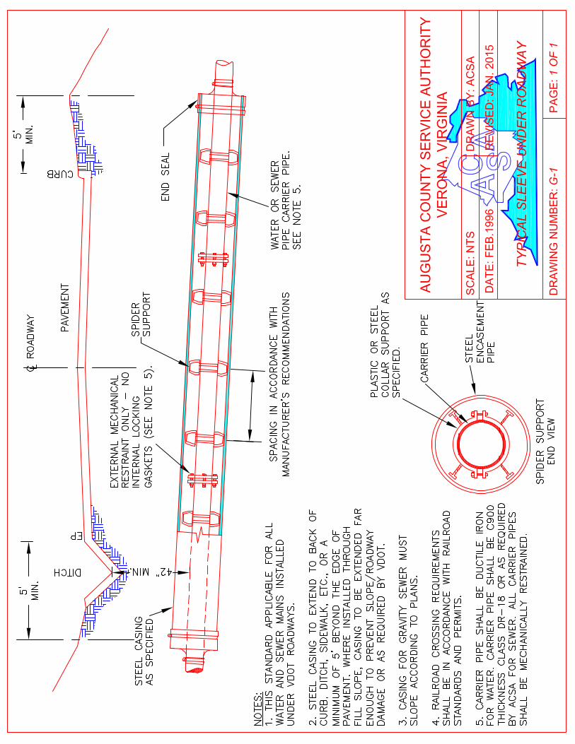
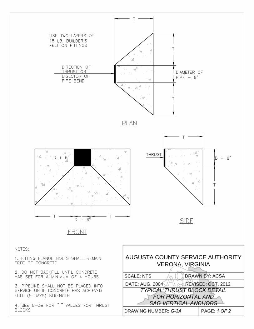
AUGUSTA COUNTY SERVICE AUTHORITY
VERONA, VIRGINIA
SCALE: NTS DRAWN BY: ACSA
DATE: AUG. 2004
TYPICAL THRUST BLOCK DETAIL
FOR HORIZONTAL AND
SAG VERTICAL ANCHORS
DRAWING NUMBER: G-3A PAGE: 1 OF 2
REVISED: OCT. 2012
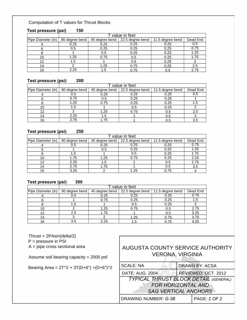
Computation of T values for Thrust Blocks
Test pressure (psi) 150
T value in feet
Pipe Diameter (in) 90 degree bend 45 degree bend 22.5 degree bend 11.5 degree bend Dead End
4
6
8
10
12
14
16
0.25
0.5
1
1.25
1.5
2
2.25
0.25
0.25
0.5
0.75
1
1.25
1.5
0.25
0.25
0.25
0.5
0.5
0.75
0.75
0.25
0.25
0.25
0.25
0.25
0.25
0.5
0.5
0.75
1.25
1.75
2
2.5
2.75
Pipe Diameter (in) 90 degree bend 45 degree bend 22.5 degree bend 11.5 degree bend Dead End
0.5
0.75
1.25
1.5
2
2.25
2.75
4
6
8
10
12
14
16
Test pressure (psi) 200
0.25
0.5
0.75
1
1.25
1.5
1.75
0.25
0.25
0.25
0.5
0.75
1
1
0.25
0.25
0.25
0.25
0.5
0.5
0.5
0.5
1
1.5
2
2.5
3
3.5
T value in feet
Pipe Diameter (in) 90 degree bend 45 degree bend 22.5 degree bend 11.5 degree bend Dead End
0.5
1
1.5
1.75
2.25
2.75
3.25
4
6
8
10
12
14
16
Test pressure (psi) 250
0.25
0.25
0.5
0.75
1
1
1.25
0.25
0.5
1
1.25
1.5
1.75
2
T value in feet
0.75
1.25
1.75
2.25
2.75
3.5
4
0.25
0.25
0.25
0.25
0.5
0.5
0.75
0.75
1.5
2
2.75
3.25
3.75
4.25
0.25
0.25
0.25
0.5
0.5
0.75
0.75
0.25
0.25
0.5
0.75
1
1.25
1.5
0.25
0.75
1
1.25
1.75
2
2.25
0.5
1
1.5
2
2.5
3
3.5
4
6
8
10
12
14
16
Pipe Diameter (in) 90 degree bend 45 degree bend 22.5 degree bend 11.5 degree bend Dead End
Test pressure (psi) 300
T value in feet
Thrust = 2PAsin(delta/2)
P = pressure in PSI
A = pipe cross sectional area
Assume soil bearing capacity = 2000 psf
Bearing Area = 2T^2 + 3T(D+6") +(D+6")^2
AUGUSTA COUNTY SERVICE AUTHORITY
VERONA, VIRGINIA
SCALE: NADRAWN BY: ACSA
DATE: AUG. 2004 REVIEWED: OCT. 2012
TYPICAL THRUST BLOCK DETAIL (GENERAL)
FOR HORIZONTAL AND
SAG VERTICAL ANCHORS
DRAWING NUMBER: G-3B PAGE: 2 OF 2
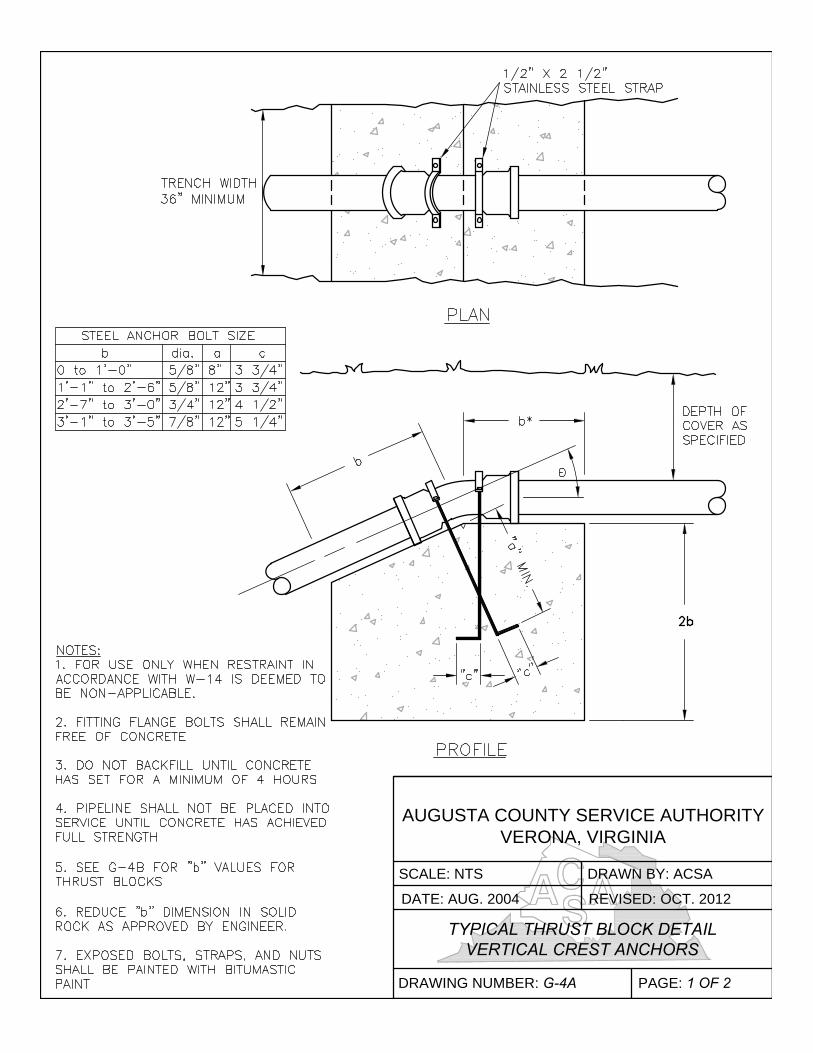
AUGUSTA COUNTY SERVICE AUTHORITY
VERONA, VIRGINIA
SCALE: NTS DRAWN BY: ACSA
DATE: AUG. 2004 REVISED:
TYPICAL THRUST BLOCK DETAIL
VERTICAL CREST ANCHORS
DRAWING NUMBER: G-4A PAGE: 1 OF 2
OCT. 2012
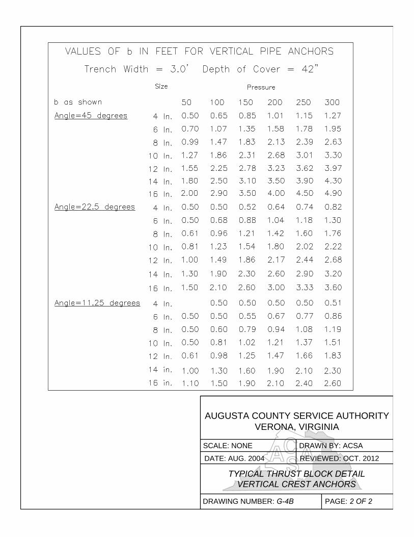
AUGUSTA COUNTY SERVICE AUTHORITY
VERONA, VIRGINIA
SCALE: NONE DRAWN BY: ACSA
DATE: AUG. 2004 REVIEWED: OCT. 2012
TYPICAL THRUST BLOCK DETAIL
VERTICAL CREST ANCHORS
DRAWING NUMBER: G-4B PAGE: 2 OF 2
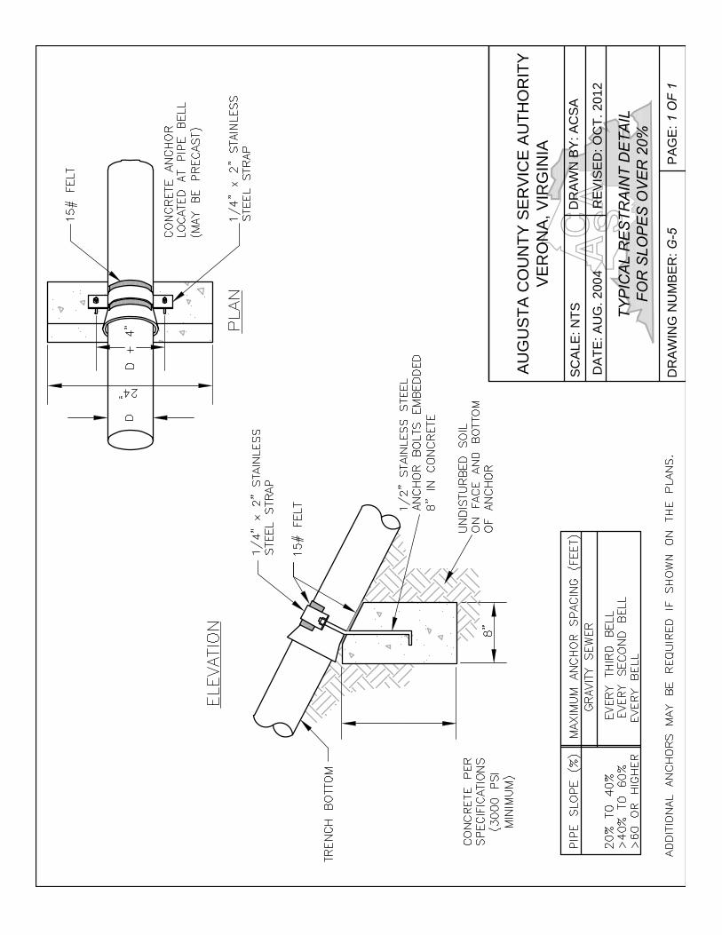
AU
GU
ST
A C
OU
NT
Y S
ER
VIC
E A
UT
HO
RIT
Y
VE
RO
NA
, V
IR
GIN
IA
SC
ALE
: N
TS
DR
AW
N B
Y: A
CS
A
DA
TE
: A
UG
. 2004
RE
VIS
ED
: O
CT
. 2012
TY
PIC
AL
R
ES
TR
AIN
T D
ET
AIL
FO
R S
LO
PE
S O
VE
R 2
0%
DR
AW
IN
G N
UM
BE
R: G
-5
PA
GE
: 1 O
F 1
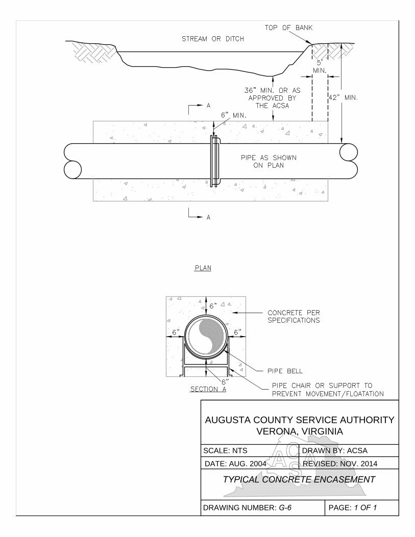
AUGUSTA COUNTY SERVICE AUTHORITY
VERONA, VIRGINIA
SCALE: NTS DRAWN BY: ACSA
DATE: AUG. 2004 REVISED: NOV. 2014
TYPICAL CONCRETE ENCASEMENT
DRAWING NUMBER: G-6 PAGE: 1 OF 1
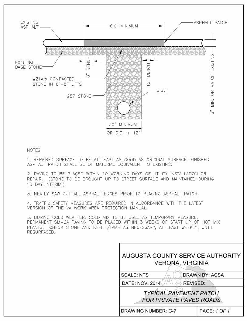
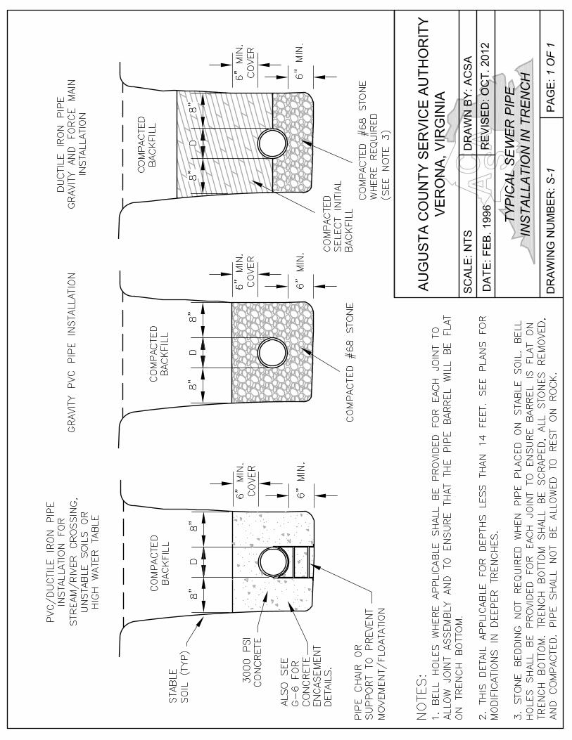
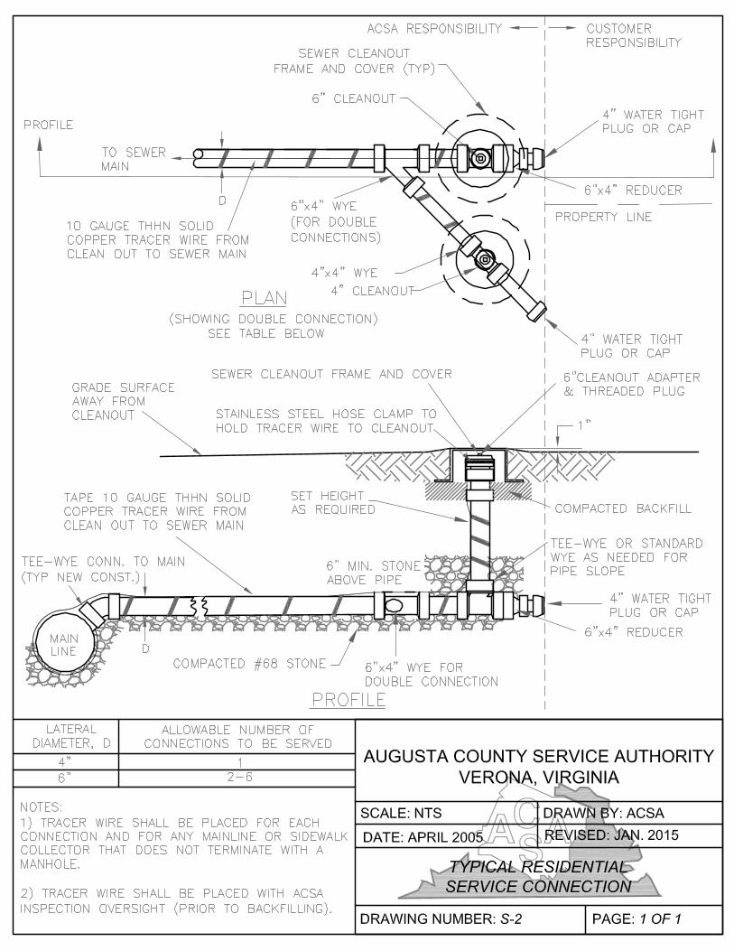
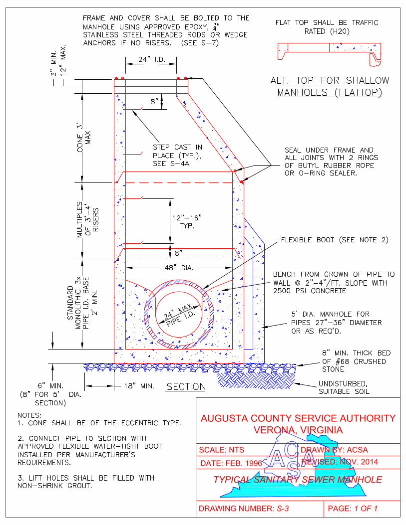
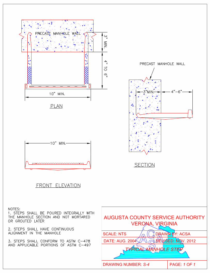
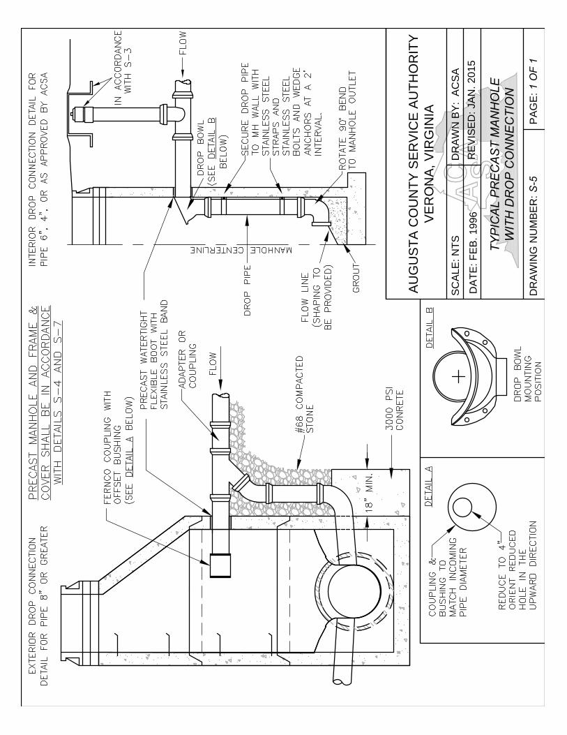
AU
GU
ST
A C
OU
NT
Y S
ER
VIC
E A
UT
HO
RIT
Y
VE
RO
NA
, V
IR
GIN
IA
SC
AL
E: N
TS
DR
AW
N B
Y: A
CS
A
DA
TE
: F
EB
. 1
99
6
RE
VIS
ED
: JA
N. 2
01
5
TY
PIC
AL
P
RE
CA
ST
M
AN
HO
LE
WIT
H D
RO
P C
ON
NE
CT
IO
N
DR
AW
IN
G N
UM
BE
R: S
-5
PA
GE
: 1
O
F 1
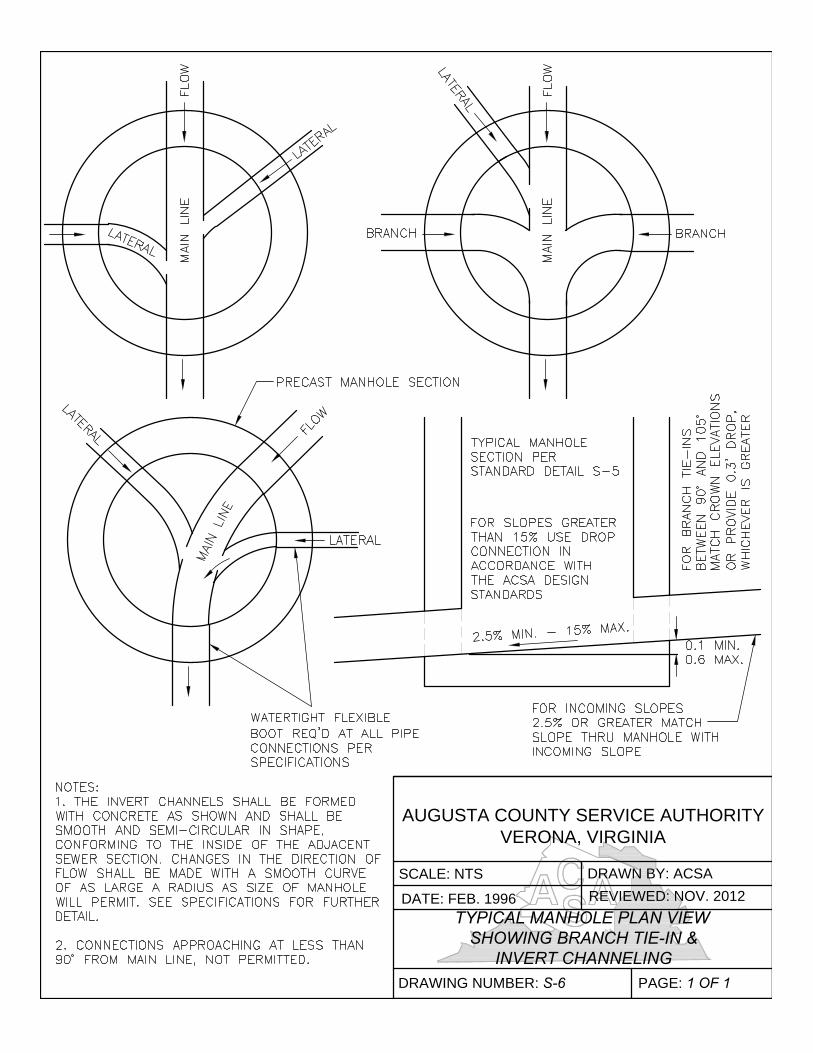
AUGUSTA COUNTY SERVICE AUTHORITY
VERONA, VIRGINIA
SCALE: NTS DRAWN BY: ACSA
DATE: FEB. 1996
REVIEWED: NOV. 2012
TYPICAL MANHOLE PLAN VIEW
SHOWING BRANCH TIE-IN &
INVERT CHANNELING
DRAWING NUMBER: S-6 PAGE: 1 OF 1
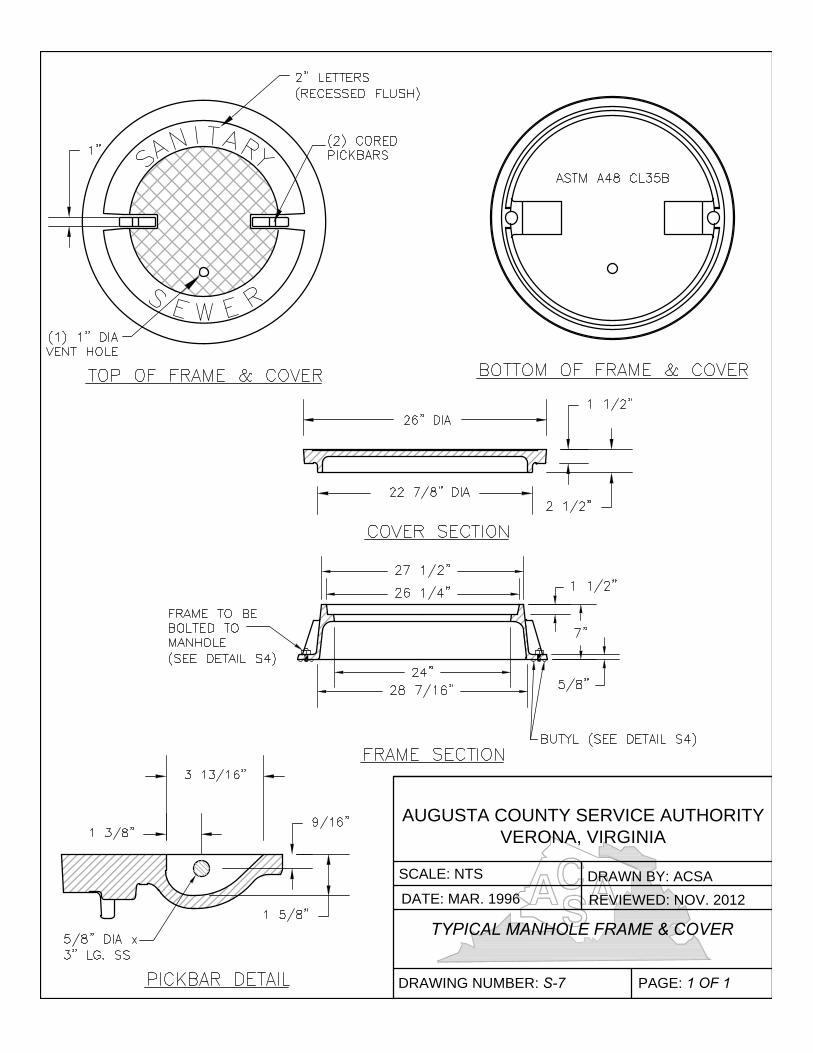
AUGUSTA COUNTY SERVICE AUTHORITY
VERONA, VIRGINIA
SCALE: NTS
DRAWN BY: ACSA
DATE: MAR. 1996REVIEWED: NOV. 2012
TYPICAL MANHOLE FRAME & COVER
DRAWING NUMBER: S-7 PAGE: 1 OF 1
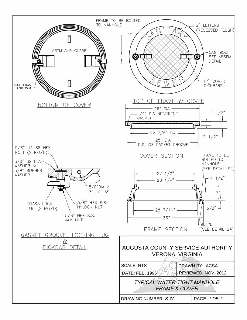
AUGUSTA COUNTY SERVICE AUTHORITY
VERONA, VIRGINIA
SCALE: NTSDRAWN BY: ACSA
DATE: FEB. 1996 REVIEWED: NOV. 2012
TYPICAL WATER-TIGHT MANHOLE
FRAME & COVER
DRAWING NUMBER: S-7A PAGE: 1 OF 1
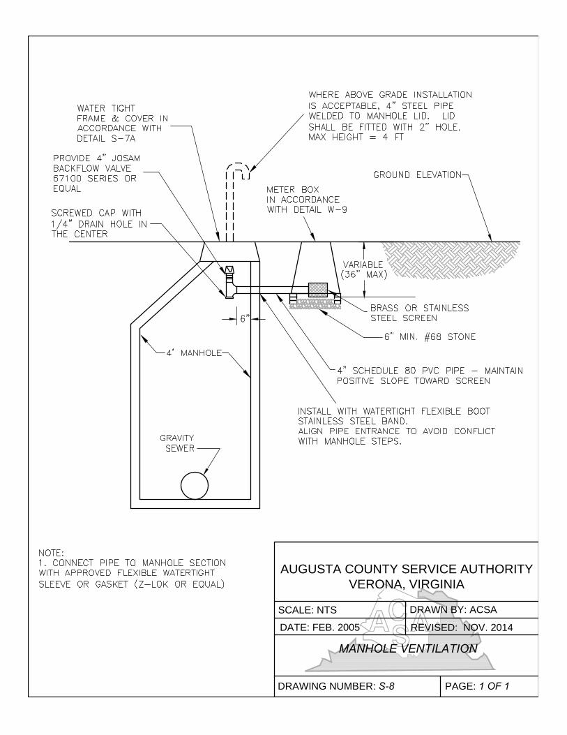
AUGUSTA COUNTY SERVICE AUTHORITY
VERONA, VIRGINIA
SCALE: NTS DRAWN BY: ACSA
DATE: FEB. 2005 REVISED: NOV. 2014
MANHOLE VENTILATION
DRAWING NUMBER: S-8 PAGE: 1 OF 1
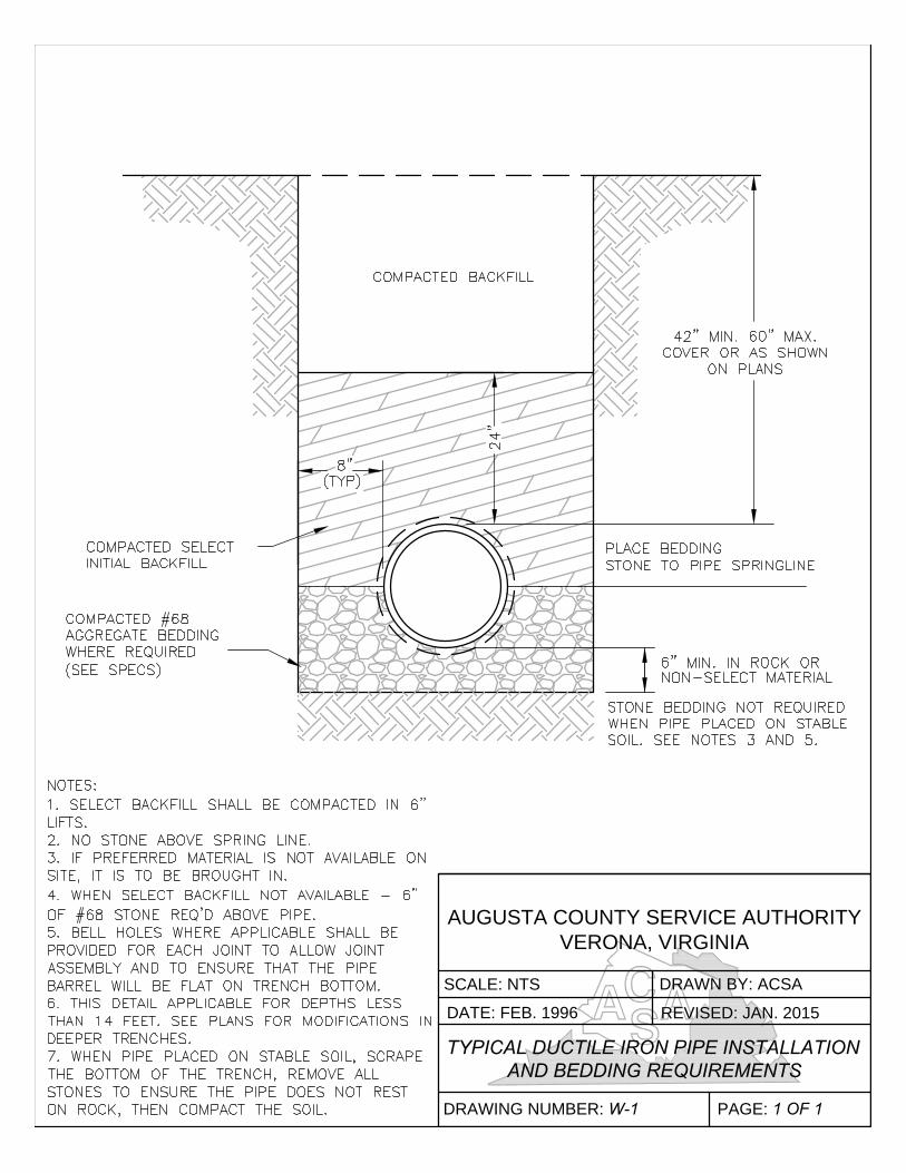
AUGUSTA COUNTY SERVICE AUTHORITY
VERONA, VIRGINIA
SCALE: NTS DRAWN BY: ACSA
DATE: FEB. 1996 REVISED: JAN. 2015
TYPICAL DUCTILE IRON PIPE INSTALLATION
AND BEDDING REQUIREMENTS
DRAWING NUMBER: W-1 PAGE: 1 OF 1
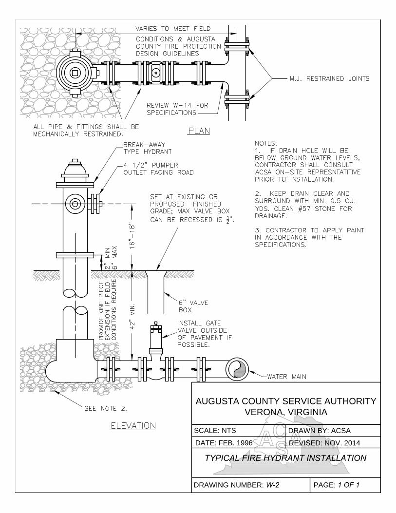
AUGUSTA COUNTY SERVICE AUTHORITY
VERONA, VIRGINIA
SCALE: NTS DRAWN BY: ACSA
DATE: FEB. 1996 REVISED: NOV. 2014
TYPICAL FIRE HYDRANT INSTALLATION
DRAWING NUMBER: W-2 PAGE: 1 OF 1
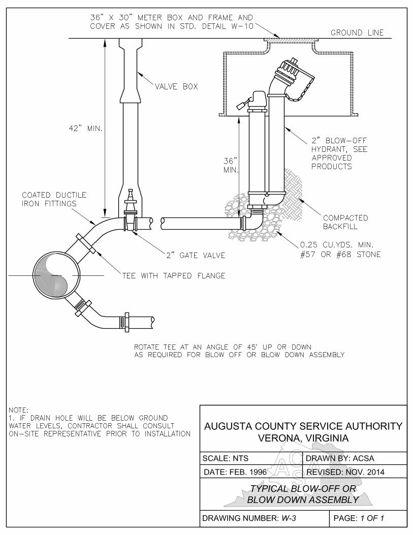
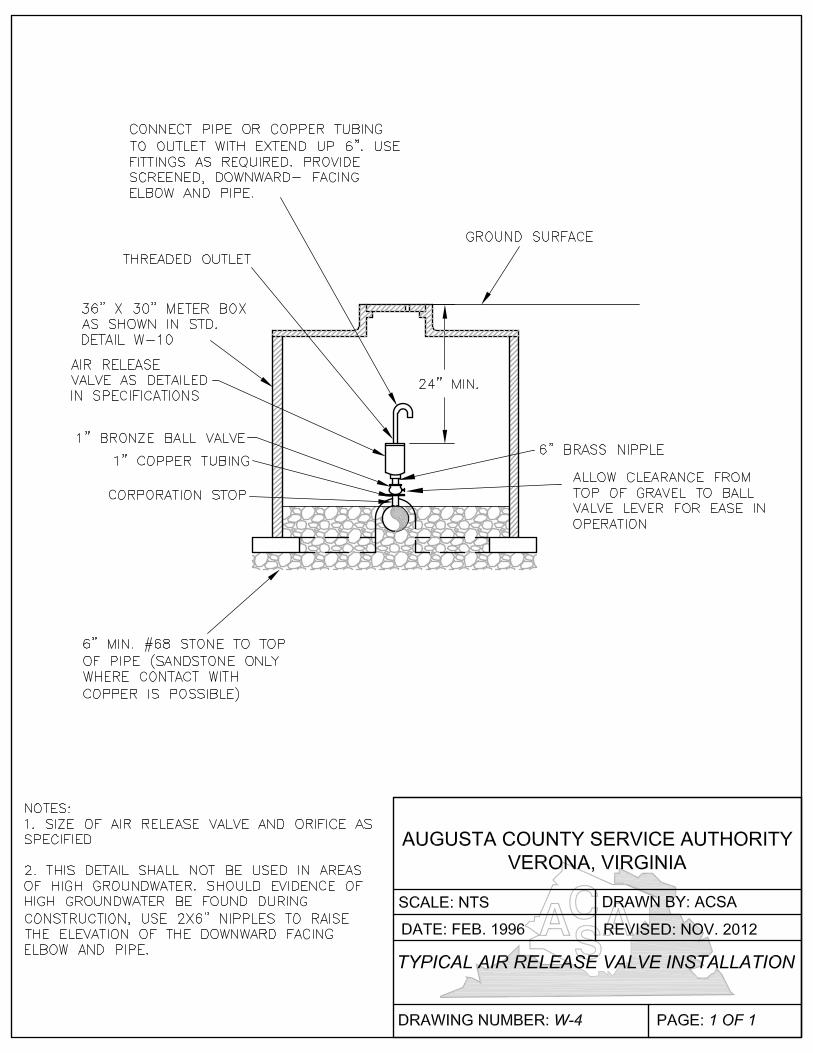
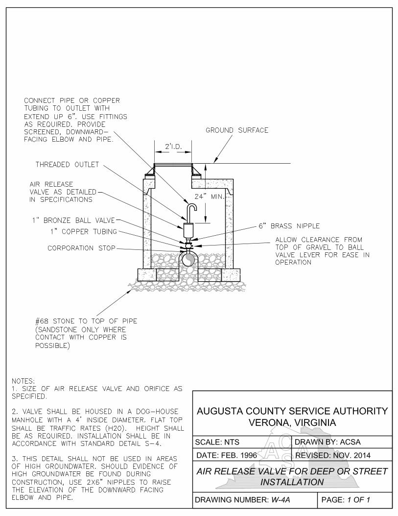
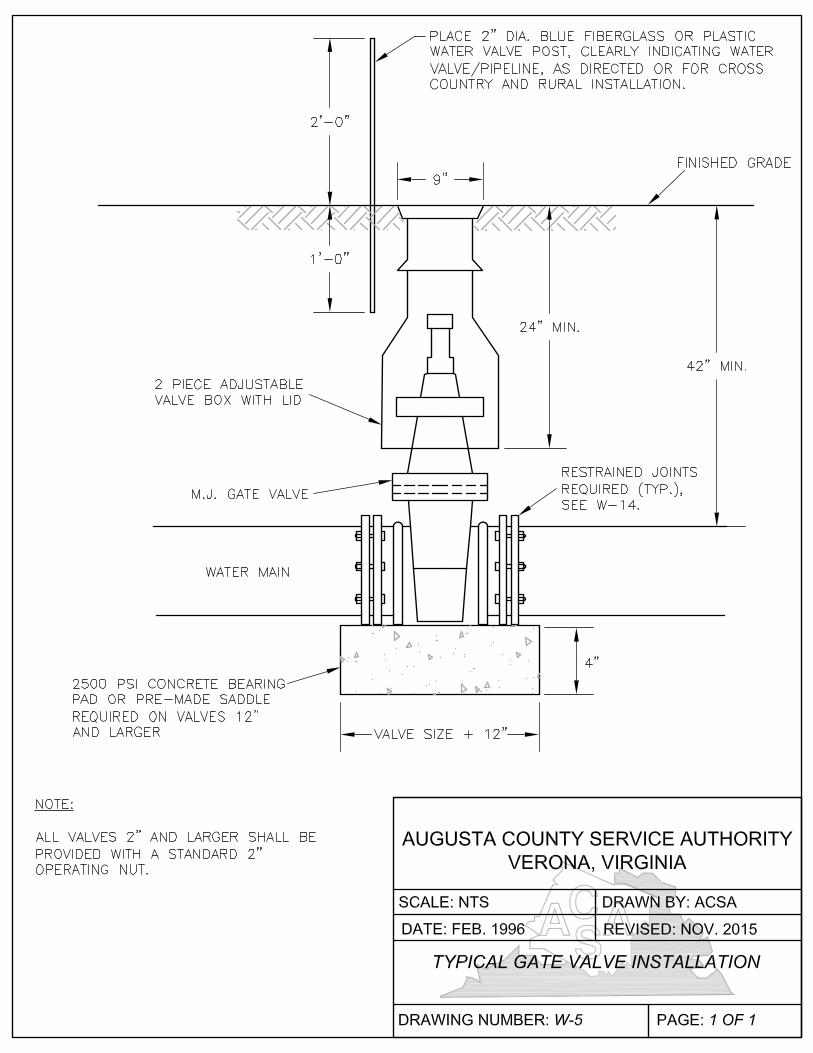
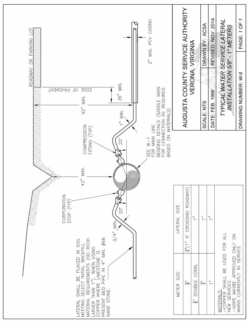
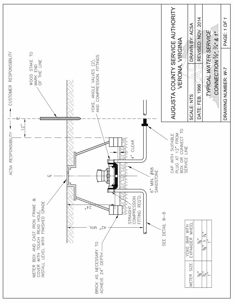
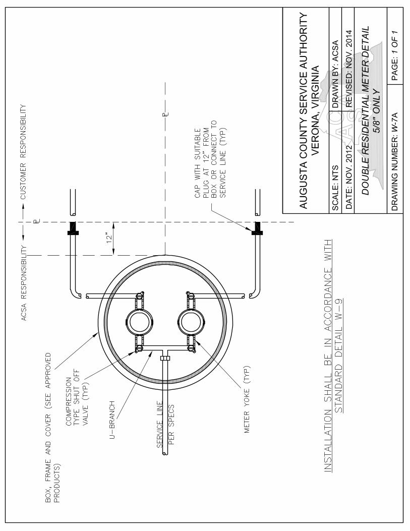
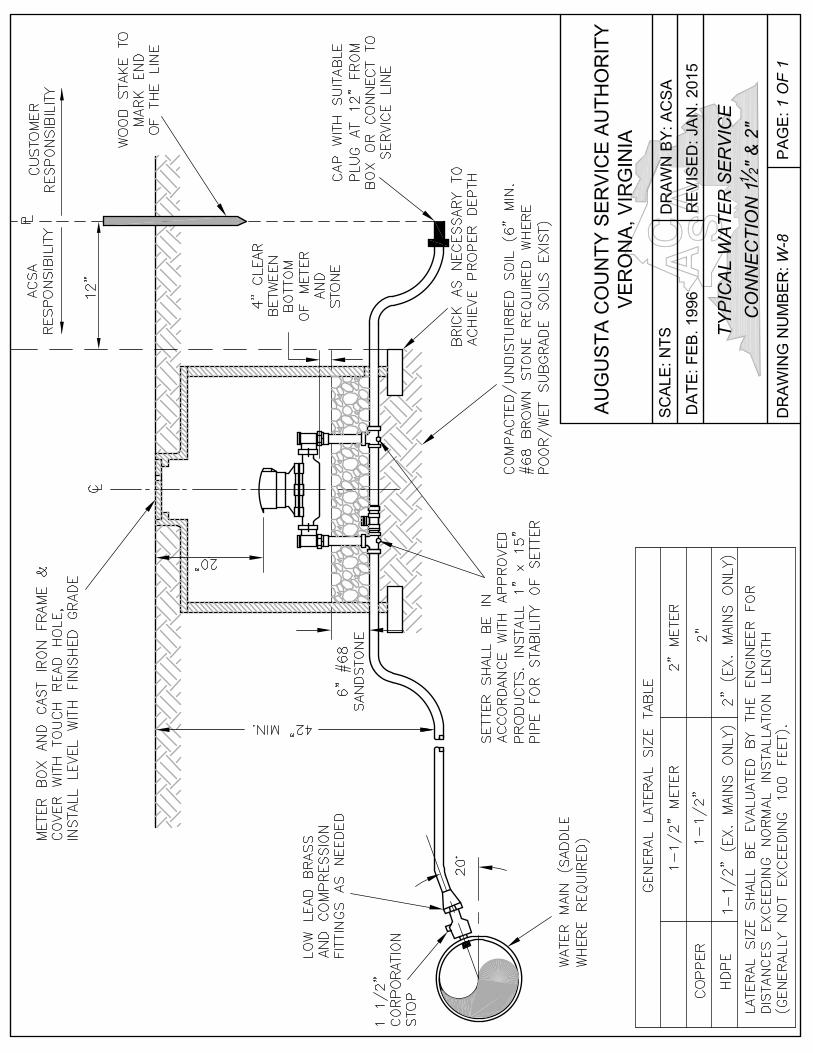
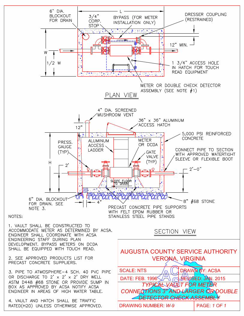
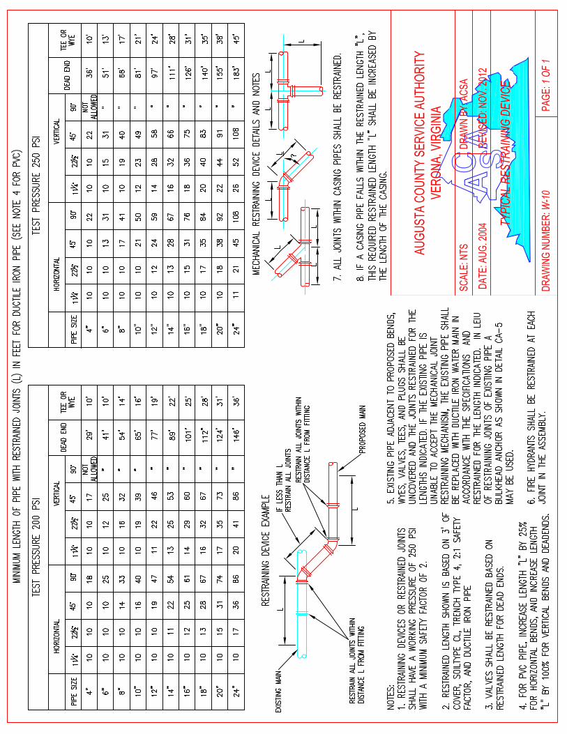
The following documents can be found at www.acsawater.com/standards a. Augusta County Submittal Checklist b. ACSA Application for Plan Review c. ACSA Hydrant Flow Test Form d. ACSA Water Meter Sizing Form e. ACSA Preconstruction Meeting f. ACSA Reservation of Treatment Capacity Agreement – Payment in Full g. ACSA Reservation of Treatment Capacity Agreement – Partial Payment
APPENDIX 1
Standard Forms
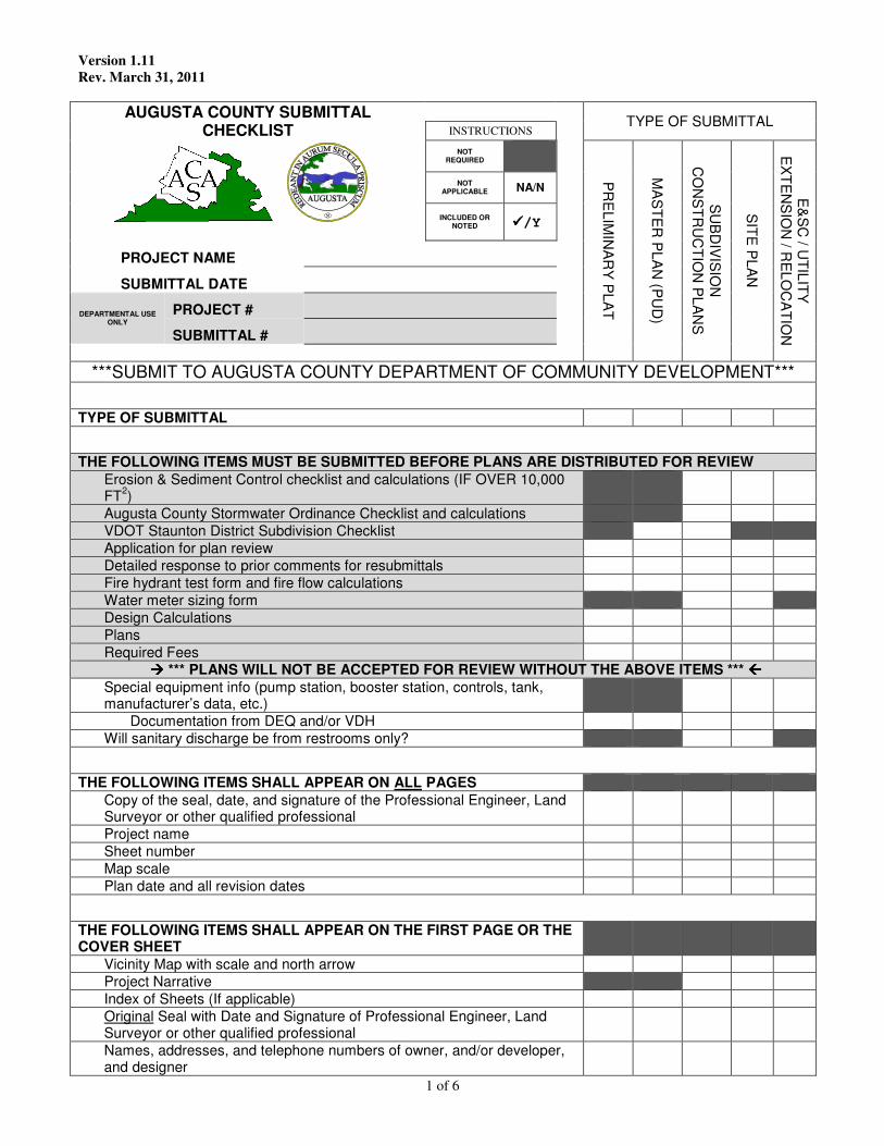
1 of 6
Version 1.11 Rev. March 31, 2011
AUGUSTA COUNTY SUBMITTAL CHECKLIST
TYPE OF SUBMITTAL
INSTRUCTIONS
NOT REQUIRED
PR
ELIM
INA
RY
PLA
T
MA
STE
R P
LAN
(PU
D)
SU
BD
IVIS
ION
C
ON
STR
UC
TION
PLA
NS
SITE
PLA
N
E&
SC
/ UTILIT
Y
EX
TE
NS
ION
/ RE
LOC
ATIO
N
NOT APPLICABLE NA/N
INCLUDED OR NOTED ����/Y
PROJECT NAME
SUBMITTAL DATE
DEPARTMENTAL USE ONLY
PROJECT #
SUBMITTAL #
***SUBMIT TO AUGUSTA COUNTY DEPARTMENT OF COMMUNITY DEVELOPMENT***
TYPE OF SUBMITTAL
THE FOLLOWING ITEMS MUST BE SUBMITTED BEFORE PLANS ARE DISTRIBUTED FOR REVIEW Erosion & Sediment Control checklist and calculations (IF OVER 10,000 FT2)
Augusta County Stormwater Ordinance Checklist and calculations VDOT Staunton District Subdivision Checklist Application for plan review Detailed response to prior comments for resubmittals Fire hydrant test form and fire flow calculations Water meter sizing form Design Calculations Plans Required Fees
���� *** PLANS WILL NOT BE ACCEPTED FOR REVIEW WITHOUT THE ABOVE ITEMS *** ���� Special equipment info (pump station, booster station, controls, tank, manufacturer’s data, etc.)
Documentation from DEQ and/or VDH Will sanitary discharge be from restrooms only?
THE FOLLOWING ITEMS SHALL APPEAR ON ALL PAGES Copy of the seal, date, and signature of the Professional Engineer, Land Surveyor or other qualified professional
Project name Sheet number Map scale Plan date and all revision dates
THE FOLLOWING ITEMS SHALL APPEAR ON THE FIRST PAGE OR THE COVER SHEET
Vicinity Map with scale and north arrow Project Narrative Index of Sheets (If applicable) Original Seal with Date and Signature of Professional Engineer, Land Surveyor or other qualified professional
Names, addresses, and telephone numbers of owner, and/or developer, and designer
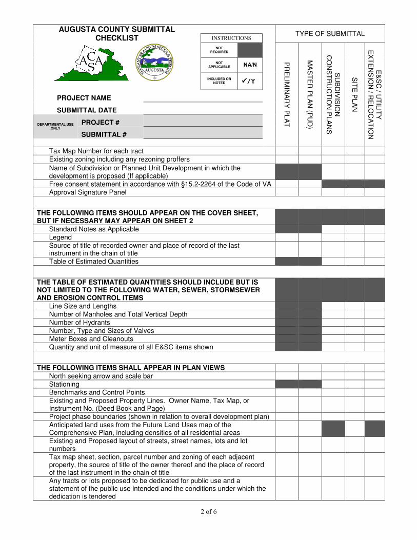
2 of 6
AUGUSTA COUNTY SUBMITTAL CHECKLIST
TYPE OF SUBMITTAL
INSTRUCTIONS
NOT REQUIRED
PR
ELIM
INA
RY
PLA
T
MA
STE
R P
LAN
(PU
D)
SU
BD
IVIS
ION
C
ON
STR
UC
TION
PLA
NS
SITE
PLA
N
E&
SC
/ UTILIT
Y
EX
TE
NS
ION
/ RE
LOC
ATIO
N
NOT APPLICABLE NA/N
INCLUDED OR NOTED ����/Y
PROJECT NAME
SUBMITTAL DATE
DEPARTMENTAL USE ONLY
PROJECT #
SUBMITTAL #
Tax Map Number for each tract Existing zoning including any rezoning proffers
Name of Subdivision or Planned Unit Development in which the development is proposed (If applicable)
Free consent statement in accordance with §15.2-2264 of the Code of VA Approval Signature Panel
THE FOLLOWING ITEMS SHOULD APPEAR ON THE COVER SHEET, BUT IF NECESSARY MAY APPEAR ON SHEET 2
Standard Notes as Applicable Legend Source of title of recorded owner and place of record of the last instrument in the chain of title
Table of Estimated Quantities
THE TABLE OF ESTIMATED QUANTITIES SHOULD INCLUDE BUT IS NOT LIMITED TO THE FOLLOWING WATER, SEWER, STORMSEWER AND EROSION CONTROL ITEMS
Line Size and Lengths Number of Manholes and Total Vertical Depth Number of Hydrants Number, Type and Sizes of Valves Meter Boxes and Cleanouts Quantity and unit of measure of all E&SC items shown
THE FOLLOWING ITEMS SHALL APPEAR IN PLAN VIEWS North seeking arrow and scale bar Stationing Benchmarks and Control Points Existing and Proposed Property Lines. Owner Name, Tax Map, or Instrument No. (Deed Book and Page)
Project phase boundaries (shown in relation to overall development plan) Anticipated land uses from the Future Land Uses map of the Comprehensive Plan, including densities of all residential areas
Existing and Proposed layout of streets, street names, lots and lot numbers
Tax map sheet, section, parcel number and zoning of each adjacent property, the source of title of the owner thereof and the place of record of the last instrument in the chain of title
Any tracts or lots proposed to be dedicated for public use and a statement of the public use intended and the conditions under which the dedication is tendered
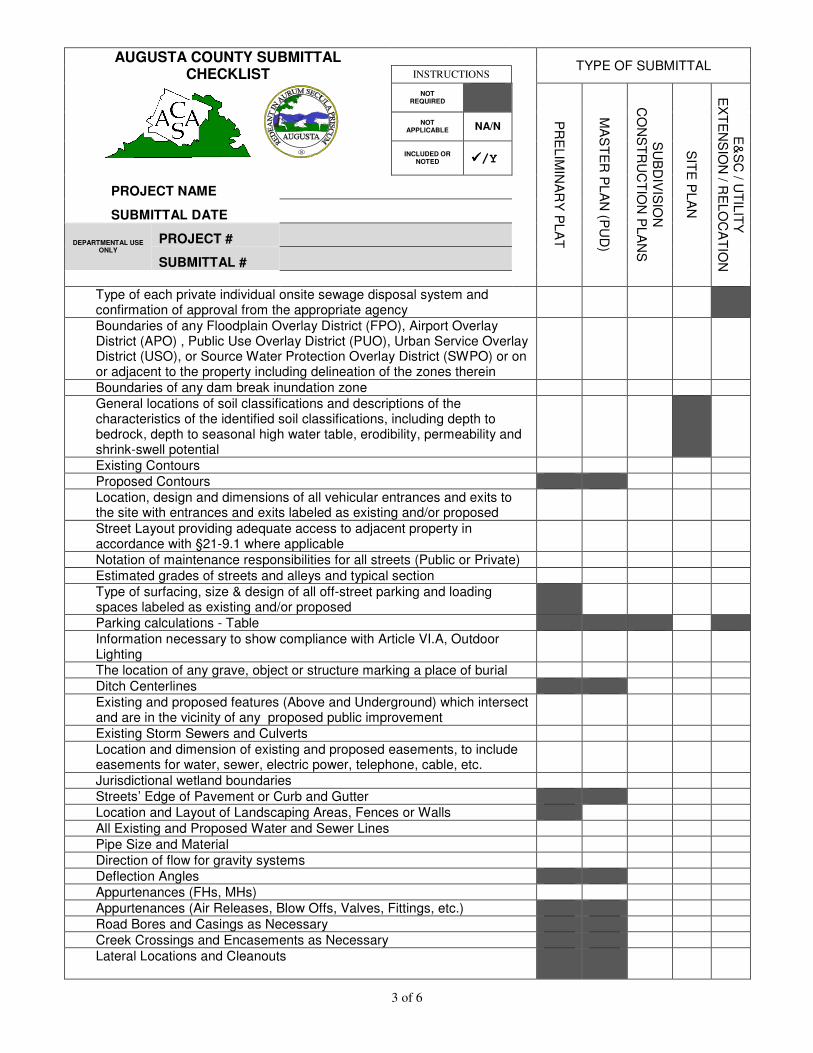
3 of 6
AUGUSTA COUNTY SUBMITTAL CHECKLIST
TYPE OF SUBMITTAL
INSTRUCTIONS
NOT REQUIRED
PR
ELIM
INA
RY
PLA
T
MA
STE
R P
LAN
(PU
D)
SU
BD
IVIS
ION
C
ON
STR
UC
TION
PLA
NS
SITE
PLA
N
E&
SC
/ UTILIT
Y
EX
TE
NS
ION
/ RE
LOC
ATIO
N
NOT APPLICABLE NA/N
INCLUDED OR NOTED ����/Y
PROJECT NAME
SUBMITTAL DATE
DEPARTMENTAL USE ONLY
PROJECT #
SUBMITTAL #
Type of each private individual onsite sewage disposal system and confirmation of approval from the appropriate agency
Boundaries of any Floodplain Overlay District (FPO), Airport Overlay District (APO) , Public Use Overlay District (PUO), Urban Service Overlay District (USO), or Source Water Protection Overlay District (SWPO) or on or adjacent to the property including delineation of the zones therein
Boundaries of any dam break inundation zone General locations of soil classifications and descriptions of the characteristics of the identified soil classifications, including depth to bedrock, depth to seasonal high water table, erodibility, permeability and shrink-swell potential
Existing Contours Proposed Contours Location, design and dimensions of all vehicular entrances and exits to the site with entrances and exits labeled as existing and/or proposed
Street Layout providing adequate access to adjacent property in accordance with §21-9.1 where applicable
Notation of maintenance responsibilities for all streets (Public or Private) Estimated grades of streets and alleys and typical section Type of surfacing, size & design of all off-street parking and loading spaces labeled as existing and/or proposed
Parking calculations - Table Information necessary to show compliance with Article VI.A, Outdoor Lighting
The location of any grave, object or structure marking a place of burial Ditch Centerlines Existing and proposed features (Above and Underground) which intersect and are in the vicinity of any proposed public improvement
Existing Storm Sewers and Culverts Location and dimension of existing and proposed easements, to include easements for water, sewer, electric power, telephone, cable, etc.
Jurisdictional wetland boundaries Streets’ Edge of Pavement or Curb and Gutter Location and Layout of Landscaping Areas, Fences or Walls All Existing and Proposed Water and Sewer Lines Pipe Size and Material Direction of flow for gravity systems Deflection Angles Appurtenances (FHs, MHs) Appurtenances (Air Releases, Blow Offs, Valves, Fittings, etc.) Road Bores and Casings as Necessary Creek Crossings and Encasements as Necessary Lateral Locations and Cleanouts
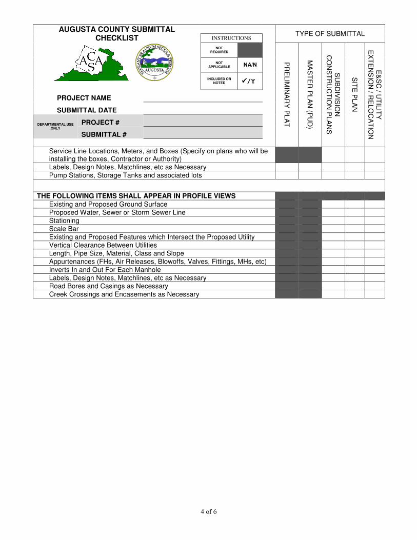
4 of 6
AUGUSTA COUNTY SUBMITTAL CHECKLIST
TYPE OF SUBMITTAL
INSTRUCTIONS
NOT REQUIRED
PR
ELIM
INA
RY
PLA
T
MA
STE
R P
LAN
(PU
D)
SU
BD
IVIS
ION
C
ON
STR
UC
TION
PLA
NS
SITE
PLA
N
E&
SC
/ UTILIT
Y
EX
TE
NS
ION
/ RE
LOC
ATIO
N
NOT APPLICABLE NA/N
INCLUDED OR NOTED ����/Y
PROJECT NAME
SUBMITTAL DATE
DEPARTMENTAL USE ONLY
PROJECT #
SUBMITTAL #
Service Line Locations, Meters, and Boxes (Specify on plans who will be installing the boxes, Contractor or Authority)
Labels, Design Notes, Matchlines, etc as Necessary Pump Stations, Storage Tanks and associated lots
THE FOLLOWING ITEMS SHALL APPEAR IN PROFILE VIEWS Existing and Proposed Ground Surface Proposed Water, Sewer or Storm Sewer Line Stationing Scale Bar Existing and Proposed Features which Intersect the Proposed Utility Vertical Clearance Between Utilities Length, Pipe Size, Material, Class and Slope Appurtenances (FHs, Air Releases, Blowoffs, Valves, Fittings, MHs, etc) Inverts In and Out For Each Manhole Labels, Design Notes, Matchlines, etc as Necessary Road Bores and Casings as Necessary Creek Crossings and Encasements as Necessary
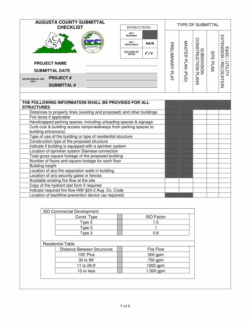
5 of 6
AUGUSTA COUNTY SUBMITTAL
CHECKLIST
TYPE OF SUBMITTAL INSTRUCTIONS
NOT REQUIRED
PR
ELIM
INA
RY
PLA
T
MA
STE
R P
LAN
(PU
D)
SU
BD
IVIS
ION
C
ON
STR
UC
TION
PLA
NS
SITE
PLA
N
E&
SC
/ UTILIT
Y
EX
TE
NS
ION
/ RE
LOC
ATIO
N
NOT APPLICABLE NA/N
INCLUDED OR NOTED ����/Y
PROJECT NAME
SUBMITTAL DATE
DEPARTMENTAL USE ONLY
PROJECT #
SUBMITTAL #
THE FOLLOWING INFORMATION SHALL BE PROVIDED FOR ALL STRUCTURES
Distances to property lines (existing and proposed) and other buildings Fire lanes if applicable Handicapped parking spaces, including unloading spaces & signage Curb cuts & building access ramps/walkways from parking spaces to building entrance(s)
Type of use of the building or type of residential structure Construction type of the proposed structure Indicate if building is equipped with a sprinker system Location of sprinkler system Siamese connection Total gross square footage of the proposed building Number of floors and square footage for each floor Building height Location of any fire separation walls in building Location of any security gates or fences Available existing fire flow at the site Copy of fire hydrant test form if required Indicate required fire flow IAW §24-2 Aug. Co. Code Location of backflow prevention device (as required)
ISO Commercial Development: Const. Type ISO Factor Type 5 1.5 Type 3 1 Type 2 0.8 Residential Table Distance Between Structures Fire Flow 100' Plus 500 gpm 30 to 99' 750 gpm 11 to 29.9' 1000 gpm 10 or less 1,500 gpm
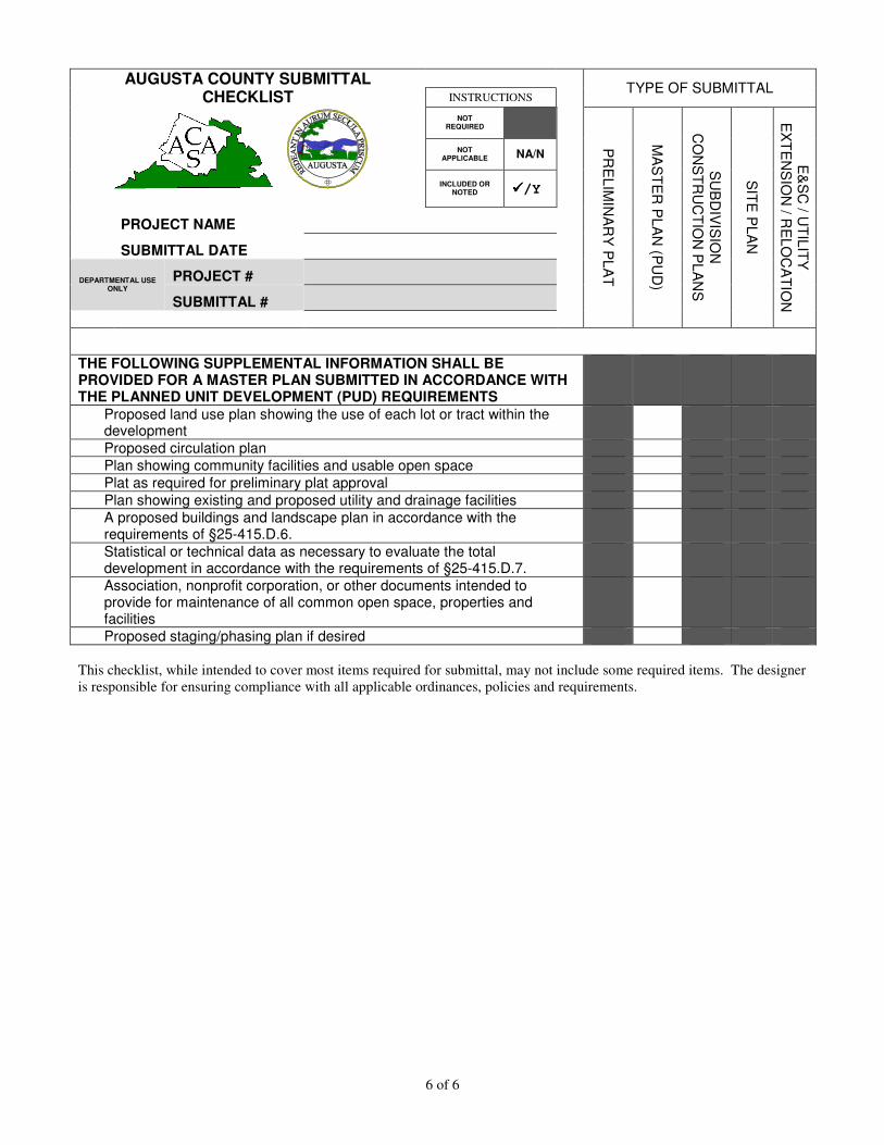
6 of 6
AUGUSTA COUNTY SUBMITTAL
CHECKLIST
TYPE OF SUBMITTAL INSTRUCTIONS
NOT REQUIRED
PR
ELIM
INA
RY
PLA
T
MA
STE
R P
LAN
(PU
D)
SU
BD
IVIS
ION
C
ON
STR
UC
TION
PLA
NS
SITE
PLA
N
E&
SC
/ UTILIT
Y
EX
TE
NS
ION
/ RE
LOC
ATIO
N
NOT APPLICABLE NA/N
INCLUDED OR NOTED ����/Y
PROJECT NAME
SUBMITTAL DATE
DEPARTMENTAL USE ONLY
PROJECT #
SUBMITTAL #
THE FOLLOWING SUPPLEMENTAL INFORMATION SHALL BE PROVIDED FOR A MASTER PLAN SUBMITTED IN ACCORDANCE WITH THE PLANNED UNIT DEVELOPMENT (PUD) REQUIREMENTS
Proposed land use plan showing the use of each lot or tract within the development
Proposed circulation plan Plan showing community facilities and usable open space Plat as required for preliminary plat approval Plan showing existing and proposed utility and drainage facilities A proposed buildings and landscape plan in accordance with the requirements of §25-415.D.6.
Statistical or technical data as necessary to evaluate the total development in accordance with the requirements of §25-415.D.7.
Association, nonprofit corporation, or other documents intended to provide for maintenance of all common open space, properties and facilities
Proposed staging/phasing plan if desired This checklist, while intended to cover most items required for submittal, may not include some required items. The designer is responsible for ensuring compliance with all applicable ordinances, policies and requirements.
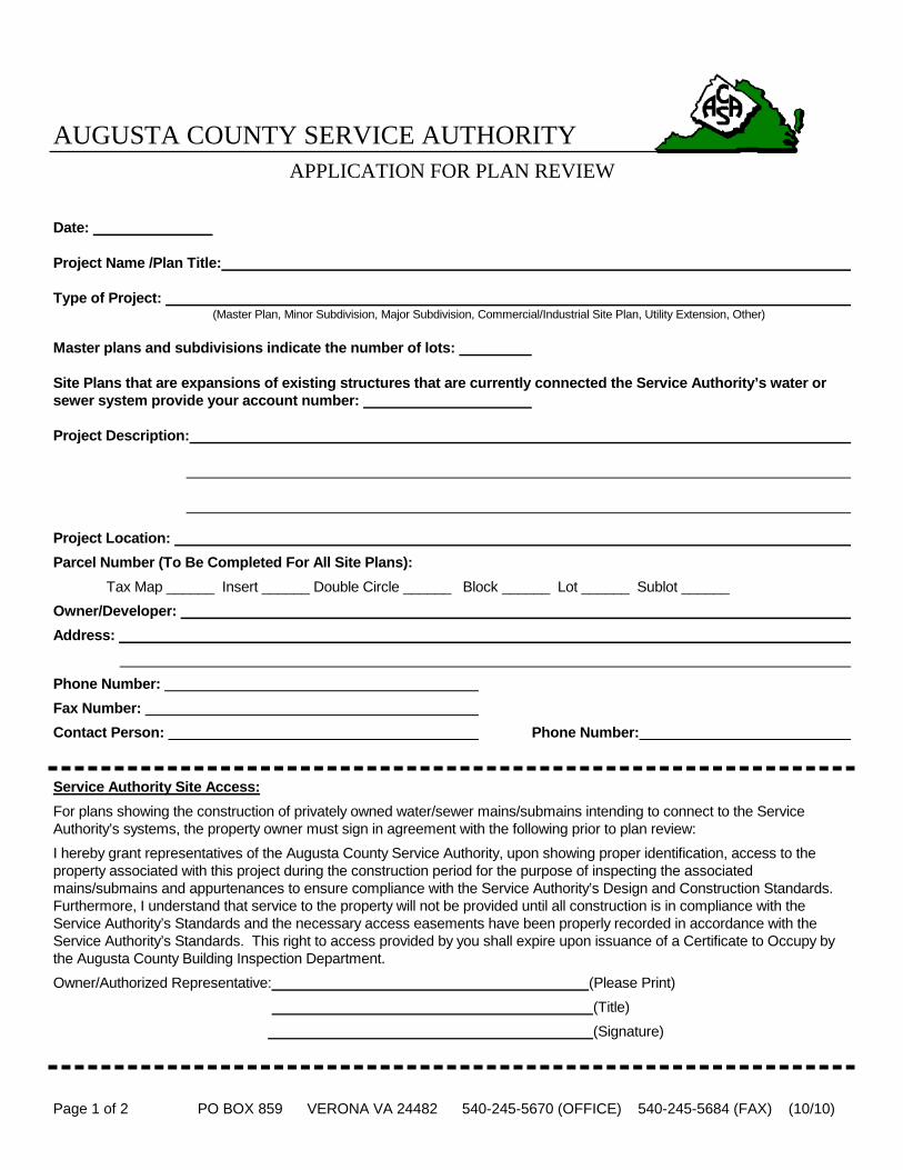
Page 1 of 2 PO BOX 859 VERONA VA 24482 540-245-5670 (OFFICE) 540-245-5684 (FAX) (10/10)
AUGUSTA COUNTY SERVICE AUTHORITY
APPLICATION FOR PLAN REVIEW Date: Project Name /Plan Title: Type of Project: (Master Plan, Minor Subdivision, Major Subdivision, Commercial/Industrial Site Plan, Utility Extension, Other)
Master plans and subdivisions indicate the number of lots: Site Plans that are expansions of existing structures that are currently connected the Service Authority’s water or sewer system provide your account number: Project Description:
Project Location:
Parcel Number (To Be Completed For All Site Plans):
Tax Map ______ Insert ______ Double Circle ______ Block ______ Lot ______ Sublot ______
Owner/Developer:
Address:
Phone Number:
Fax Number:
Contact Person: Phone Number:
Service Authority Site Access:
For plans showing the construction of privately owned water/sewer mains/submains intending to connect to the Service Authority’s systems, the property owner must sign in agreement with the following prior to plan review:
I hereby grant representatives of the Augusta County Service Authority, upon showing proper identification, access to the property associated with this project during the construction period for the purpose of inspecting the associated mains/submains and appurtenances to ensure compliance with the Service Authority’s Design and Construction Standards. Furthermore, I understand that service to the property will not be provided until all construction is in compliance with the Service Authority’s Standards and the necessary access easements have been properly recorded in accordance with the Service Authority’s Standards. This right to access provided by you shall expire upon issuance of a Certificate to Occupy by the Augusta County Building Inspection Department.
Owner/Authorized Representative: (Please Print)
(Title)
(Signature)
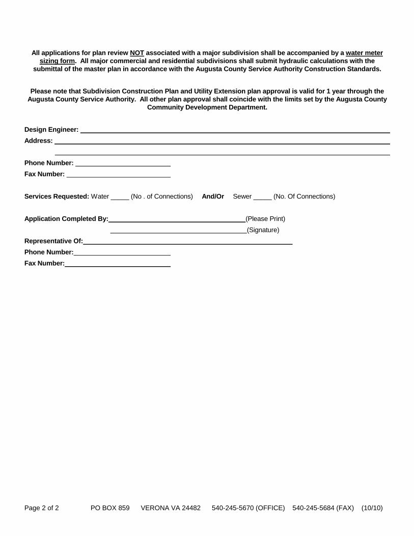
Page 2 of 2 PO BOX 859 VERONA VA 24482 540-245-5670 (OFFICE) 540-245-5684 (FAX) (10/10)
All applications for plan review NOT associated with a major subdivision shall be accompanied by a water meter sizing form. All major commercial and residential subdivisions shall submit hydraulic calculations with the
submittal of the master plan in accordance with the Augusta County Service Authority Construction Standards.
Please note that Subdivision Construction Plan and Utility Extension plan approval is valid for 1 year through the Augusta County Service Authority. All other plan approval shall coincide with the limits set by the Augusta County
Community Development Department.
Design Engineer:
Address:
Phone Number:
Fax Number:
Services Requested: Water _____ (No . of Connections) And/Or Sewer _____ (No. Of Connections)
Application Completed By: (Please Print)
(Signature)
Representative Of:
Phone Number:
Fax Number:
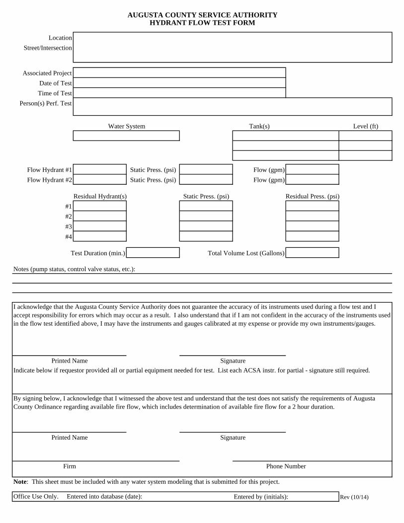
Location
Street/Intersection
Associated Project
Date of Test
Time of Test
Person(s) Perf. Test
Tank(s) Level (ft)
Flow Hydrant #1 Static Press. (psi) Flow (gpm)
Flow Hydrant #2 Static Press. (psi) Flow (gpm)
Residual Hydrant(s) Static Press. (psi) Residual Press. (psi)
#1
#2
#3
#4
Test Duration (min.) Total Volume Lost (Gallons)
Notes (pump status, control valve status, etc.):
Note: This sheet must be included with any water system modeling that is submitted for this project.
Entered by (initials): Rev (10/14)
AUGUSTA COUNTY SERVICE AUTHORITYHYDRANT FLOW TEST FORM
Printed Name Signature
Indicate below if requestor provided all or partial equipment needed for test. List each ACSA instr. for partial - signature still required.
Water System
Printed Name Signature
I acknowledge that the Augusta County Service Authority does not guarantee the accuracy of its instruments used during a flow test and I accept responsibility for errors which may occur as a result. I also understand that if I am not confident in the accuracy of the instruments used in the flow test identified above, I may have the instruments and gauges calibrated at my expense or provide my own instruments/gauges.
Office Use Only. Entered into database (date):
Firm
By signing below, I acknowledge that I witnessed the above test and understand that the test does not satisfy the requirements of Augusta County Ordinance regarding available fire flow, which includes determination of available fire flow for a 2 hour duration.
Phone Number
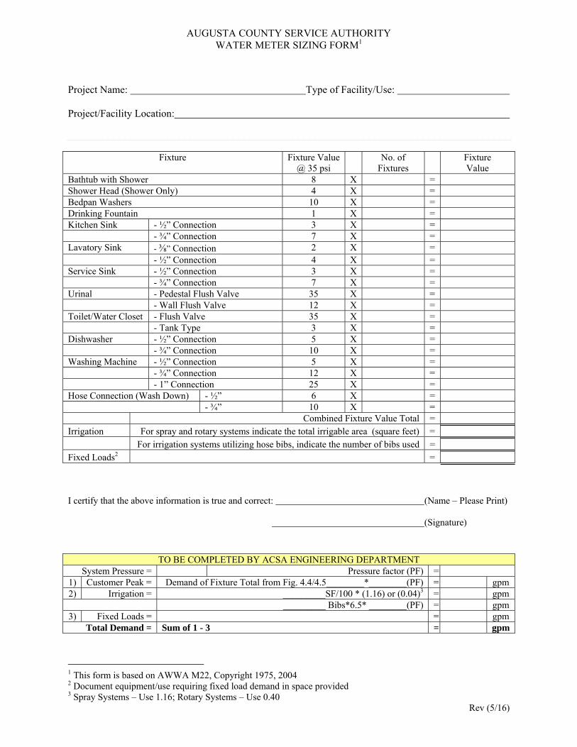
Rev (5/16)
AUGUSTA COUNTY SERVICE AUTHORITY WATER METER SIZING FORM1
Project Name: Type of Facility/Use: Project/Facility Location:
Fixture Fixture Value @ 35 psi
No. of Fixtures
Fixture Value
Bathtub with Shower 8 X = Shower Head (Shower Only) 4 X = Bedpan Washers 10 X = Drinking Fountain 1 X = Kitchen Sink - ½” Connection 3 X = - ¾” Connection 7 X = Lavatory Sink - ⅜” Connection 2 X = - ½” Connection 4 X = Service Sink - ½” Connection 3 X = - ¾” Connection 7 X = Urinal - Pedestal Flush Valve 35 X = - Wall Flush Valve 12 X = Toilet/Water Closet - Flush Valve 35 X = - Tank Type 3 X = Dishwasher - ½” Connection 5 X = - ¾” Connection 10 X = Washing Machine - ½” Connection 5 X = - ¾” Connection 12 X = - 1” Connection 25 X = Hose Connection (Wash Down) - ½” 6 X = - ¾” 10 X = Combined Fixture Value Total = Irrigation For spray and rotary systems indicate the total irrigable area (square feet) = For irrigation systems utilizing hose bibs, indicate the number of bibs used = Fixed Loads2 =
I certify that the above information is true and correct: (Name – Please Print) (Signature)
TO BE COMPLETED BY ACSA ENGINEERING DEPARTMENT System Pressure = Pressure factor (PF) =
1) Customer Peak = Demand of Fixture Total from Fig. 4.4/4.5________*________(PF) = gpm 2) Irrigation = _________SF/100 * (1.16) or (0.04)3 = gpm _________ Bibs*6.5* ________(PF) = gpm 3) Fixed Loads = = gpm
Total Demand = Sum of 1 - 3 = gpm
1 This form is based on AWWA M22, Copyright 1975, 2004 2 Document equipment/use requiring fixed load demand in space provided 3 Spray Systems – Use 1.16; Rotary Systems – Use 0.40
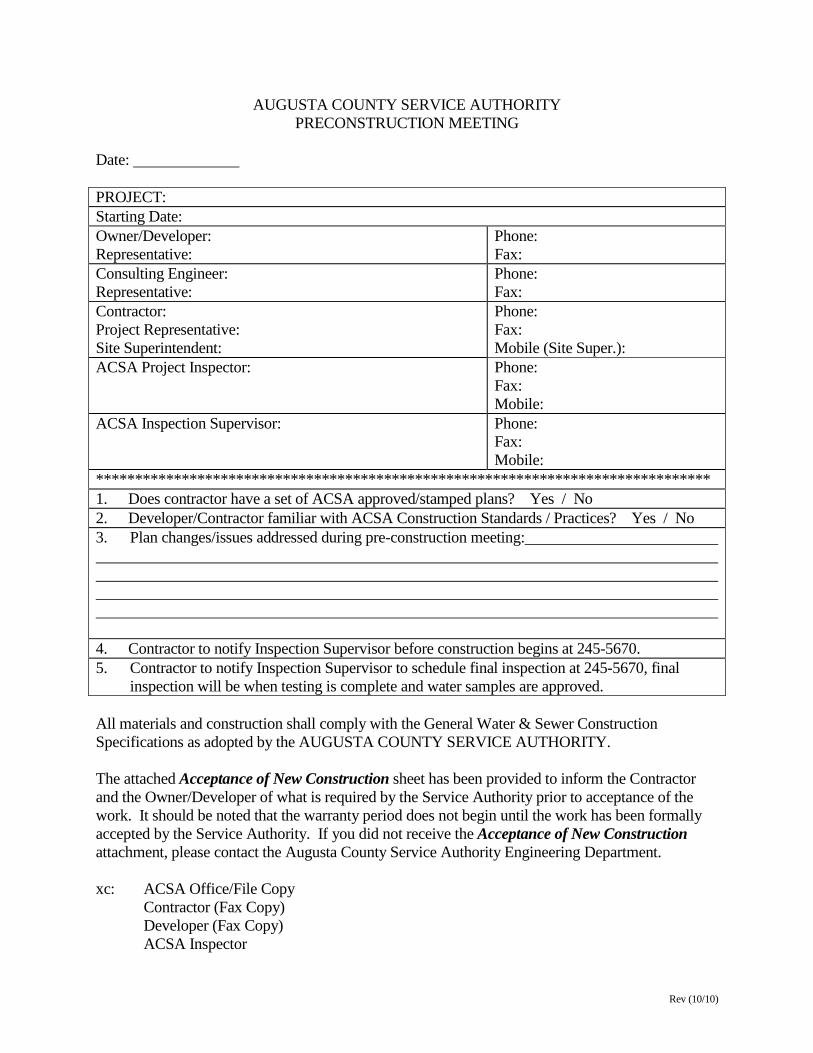
Rev (10/10)
AUGUSTA COUNTY SERVICE AUTHORITY PRECONSTRUCTION MEETING
Date: PROJECT: Starting Date: Owner/Developer: Representative:
Phone: Fax:
Consulting Engineer: Representative:
Phone: Fax:
Contractor: Project Representative: Site Superintendent:
Phone: Fax: Mobile (Site Super.):
ACSA Project Inspector: Phone: Fax: Mobile:
ACSA Inspection Supervisor: Phone: Fax: Mobile:
******************************************************************************* 1. Does contractor have a set of ACSA approved/stamped plans? Yes / No 2. Developer/Contractor familiar with ACSA Construction Standards / Practices? Yes / No 3. Plan changes/issues addressed during pre-construction meeting: 4. Contractor to notify Inspection Supervisor before construction begins at 245-5670. 5. Contractor to notify Inspection Supervisor to schedule final inspection at 245-5670, final inspection will be when testing is complete and water samples are approved. All materials and construction shall comply with the General Water & Sewer Construction Specifications as adopted by the AUGUSTA COUNTY SERVICE AUTHORITY. The attached Acceptance of New Construction sheet has been provided to inform the Contractor and the Owner/Developer of what is required by the Service Authority prior to acceptance of the work. It should be noted that the warranty period does not begin until the work has been formally accepted by the Service Authority. If you did not receive the Acceptance of New Construction attachment, please contact the Augusta County Service Authority Engineering Department. xc: ACSA Office/File Copy Contractor (Fax Copy) Developer (Fax Copy) ACSA Inspector
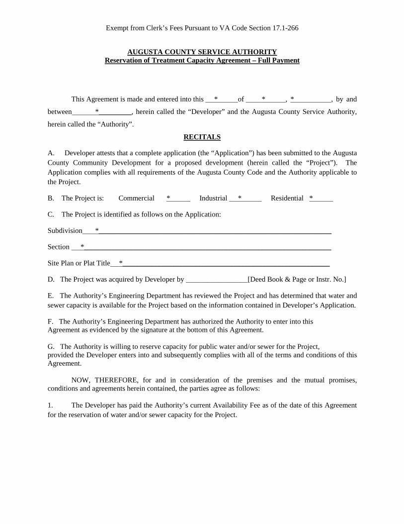
Exempt from Clerk’s Fees Pursuant to VA Code Section 17.1-266
AUGUSTA COUNTY SERVICE AUTHORITY Reservation of Treatment Capacity Agreement – Full Payment
This Agreement is made and entered into this * of * , * , by and
between *_________, herein called the “Developer” and the Augusta County Service Authority,
herein called the “Authority”.
RECITALS
A. Developer attests that a complete application (the “Application”) has been submitted to the Augusta County Community Development for a proposed development (herein called the “Project”). The Application complies with all requirements of the Augusta County Code and the Authority applicable to the Project.
B. The Project is: Commercial * Industrial * Residential *
C. The Project is identified as follows on the Application:
Subdivision *________________________________________________________________
Section *____________________________________________________________________
Site Plan or Plat Title *_________________________________________________________
D. The Project was acquired by Developer by _________________[Deed Book & Page or Instr. No.]
E. The Authority’s Engineering Department has reviewed the Project and has determined that water and sewer capacity is available for the Project based on the information contained in Developer’s Application.
F. The Authority’s Engineering Department has authorized the Authority to enter into this Agreement as evidenced by the signature at the bottom of this Agreement. G. The Authority is willing to reserve capacity for public water and/or sewer for the Project, provided the Developer enters into and subsequently complies with all of the terms and conditions of this Agreement. NOW, THEREFORE, for and in consideration of the premises and the mutual promises, conditions and agreements herein contained, the parties agree as follows: 1. The Developer has paid the Authority’s current Availability Fee as of the date of this Agreement for the reservation of water and/or sewer capacity for the Project.
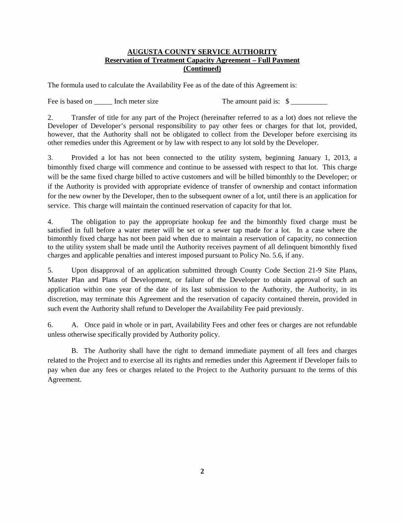
2
AUGUSTA COUNTY SERVICE AUTHORITY Reservation of Treatment Capacity Agreement – Full Payment
(Continued)
The formula used to calculate the Availability Fee as of the date of this Agreement is:
Fee is based on _____ Inch meter size The amount paid is: $ __________
2. Transfer of title for any part of the Project (hereinafter referred to as a lot) does not relieve the Developer of Developer’s personal responsibility to pay other fees or charges for that lot, provided, however, that the Authority shall not be obligated to collect from the Developer before exercising its other remedies under this Agreement or by law with respect to any lot sold by the Developer.
3. Provided a lot has not been connected to the utility system, beginning January 1, 2013, a bimonthly fixed charge will commence and continue to be assessed with respect to that lot. This charge will be the same fixed charge billed to active customers and will be billed bimonthly to the Developer; or if the Authority is provided with appropriate evidence of transfer of ownership and contact information for the new owner by the Developer, then to the subsequent owner of a lot, until there is an application for service. This charge will maintain the continued reservation of capacity for that lot.
4. The obligation to pay the appropriate hookup fee and the bimonthly fixed charge must be satisfied in full before a water meter will be set or a sewer tap made for a lot. In a case where the bimonthly fixed charge has not been paid when due to maintain a reservation of capacity, no connection to the utility system shall be made until the Authority receives payment of all delinquent bimonthly fixed charges and applicable penalties and interest imposed pursuant to Policy No. 5.6, if any.
5. Upon disapproval of an application submitted through County Code Section 21-9 Site Plans, Master Plan and Plans of Development, or failure of the Developer to obtain approval of such an application within one year of the date of its last submission to the Authority, the Authority, in its discretion, may terminate this Agreement and the reservation of capacity contained therein, provided in such event the Authority shall refund to Developer the Availability Fee paid previously.
6. A. Once paid in whole or in part, Availability Fees and other fees or charges are not refundable unless otherwise specifically provided by Authority policy.
B. The Authority shall have the right to demand immediate payment of all fees and charges related to the Project and to exercise all its rights and remedies under this Agreement if Developer fails to pay when due any fees or charges related to the Project to the Authority pursuant to the terms of this Agreement.

3
AUGUSTA COUNTY SERVICE AUTHORITY
Reservation of Treatment Capacity Agreement – Full Payment (Continued)
C. The Authority will not approve any building permit or provide service for lot unless and until all fees and charges for that lot have been paid in accordance with this Agreement.
D. Inspection and ancillary fees related to the Project will be billed separately by the Authority to Developer, with bills payable within 30 days of their date.
E. Except as expressly set out in this Agreement, the relationship between Developer and the Authority shall be governed by the Authority’s policies, procedures and rules in effect at any given time.
F. If any fee is not paid by the responsible party (Developer and/or Developer’s successor in title) the responsible party shall be liable for all damages, costs and expenses, including attorney's fees, incurred by the Authority related to or as a result of the default, in collecting payment, or in enforcing this Agreement.
G. This Agreement shall be binding on the parties signing it as Owner/Developer with respect to all or any part of the Project, and on successors in title to the Developer who assume Developer’s obligations, in every case jointly and severally, and is to be recorded in the Clerk’s Office of the Circuit Court of Augusta County. Certain terms and conditions of this Agreement affect lots in the Project owned by successors in title to the Developer even if they do not assume Developer’s obligations.
H. In the event of any changes in governmental laws or regulations applicable to the Authority utility system which effectively reduces system capacity, the Authority, in its discretion, may terminate this Agreement and the reservation of capacity contained therein, provided in such event the Authority shall refund to the then current owner of the Project, or of any lot therein which is separately titled, any Availability Fee or bimonthly fixed charges, or portions thereof, paid previously.
I. Nothing in this Agreement shall be construed to modify or limit any right or remedy available to the Authority under applicable law.
[SIGNATURE PAGE FOLLOWS]
4
AUGUSTA COUNTY SERVICE AUTHORITY
Reservation of Treatment Capacity Agreement – Full Payment (Continued)
WITNESS the following signatures:
_____________________________________ [Entity] By: _____________________________________(SEAL) Title COMMONWEALTH OF VIRGINIA COUNTY OF AUGUSTA The foregoing instrument was acknowledged before me this ___ day of _________________, 20__, by _______________________(name), ______________________ (title) of _____________________________, (entity) a Virginia _____________________, on behalf of the_________________________________. (entity) ___________________________________ Notary Public Registration No. ______________________ My commission expires: _______________________ Seen and approved: Engineer’s Approval ___________________________ F:\61\JWS\Business General\ACSA\Reserve Policy\Full Payment Reservation of Treatment Capacity.1-19-11.doc
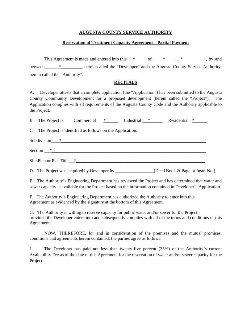
AUGUSTA COUNTY SERVICE AUTHORITY
Reservation of Treatment Capacity Agreement – Partial Payment
This Agreement is made and entered into this * of * , * , by and
between *_________, herein called the “Developer” and the Augusta County Service Authority,
herein called the “Authority”.
RECITALS
A. Developer attests that a complete application (the “Application”) has been submitted to the Augusta County Community Development for a proposed development (herein called the “Project”). The Application complies with all requirements of the Augusta County Code and the Authority applicable to the Project.
B. The Project is: Commercial * Industrial * Residential *
C. The Project is identified as follows on the Application:
Subdivision *________________________________________________________________
Section *____________________________________________________________________
Site Plan or Plat Title *_________________________________________________________
D. The Project was acquired by Developer by _________________[Deed Book & Page or Instr. No.]
E. The Authority’s Engineering Department has reviewed the Project and has determined that water and sewer capacity is available for the Project based on the information contained in Developer’s Application.
F. The Authority’s Engineering Department has authorized the Authority to enter into this Agreement as evidenced by the signature at the bottom of this Agreement. G. The Authority is willing to reserve capacity for public water and/or sewer for the Project, provided the Developer enters into and subsequently complies with all of the terms and conditions of this Agreement. NOW, THEREFORE, for and in consideration of the premises and the mutual promises, conditions and agreements herein contained, the parties agree as follows: 1. The Developer has paid not less than twenty-five percent (25%) of the Authority’s current Availability Fee as of the date of this Agreement for the reservation of water and/or sewer capacity for the Project.
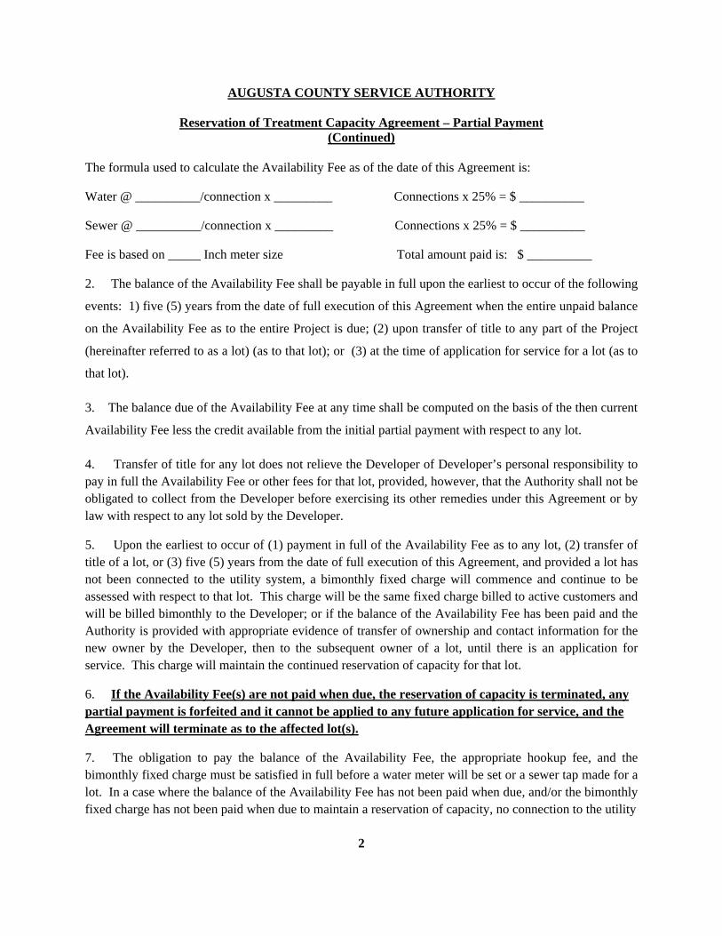
2
AUGUSTA COUNTY SERVICE AUTHORITY
Reservation of Treatment Capacity Agreement – Partial Payment (Continued)
The formula used to calculate the Availability Fee as of the date of this Agreement is:
Water @ __________/connection x _________ Connections x 25% = $ __________
Sewer @ __________/connection x _________ Connections x 25% = $ __________
Fee is based on _____ Inch meter size Total amount paid is: $ __________
2. The balance of the Availability Fee shall be payable in full upon the earliest to occur of the following
events: 1) five (5) years from the date of full execution of this Agreement when the entire unpaid balance
on the Availability Fee as to the entire Project is due; (2) upon transfer of title to any part of the Project
(hereinafter referred to as a lot) (as to that lot); or (3) at the time of application for service for a lot (as to
that lot).
3. The balance due of the Availability Fee at any time shall be computed on the basis of the then current
Availability Fee less the credit available from the initial partial payment with respect to any lot.
4. Transfer of title for any lot does not relieve the Developer of Developer’s personal responsibility to pay in full the Availability Fee or other fees for that lot, provided, however, that the Authority shall not be obligated to collect from the Developer before exercising its other remedies under this Agreement or by law with respect to any lot sold by the Developer.
5. Upon the earliest to occur of (1) payment in full of the Availability Fee as to any lot, (2) transfer of title of a lot, or (3) five (5) years from the date of full execution of this Agreement, and provided a lot has not been connected to the utility system, a bimonthly fixed charge will commence and continue to be assessed with respect to that lot. This charge will be the same fixed charge billed to active customers and will be billed bimonthly to the Developer; or if the balance of the Availability Fee has been paid and the Authority is provided with appropriate evidence of transfer of ownership and contact information for the new owner by the Developer, then to the subsequent owner of a lot, until there is an application for service. This charge will maintain the continued reservation of capacity for that lot.
6. If the Availability Fee(s) are not paid when due, the reservation of capacity is terminated, any partial payment is forfeited and it cannot be applied to any future application for service, and the Agreement will terminate as to the affected lot(s).
7. The obligation to pay the balance of the Availability Fee, the appropriate hookup fee, and the bimonthly fixed charge must be satisfied in full before a water meter will be set or a sewer tap made for a lot. In a case where the balance of the Availability Fee has not been paid when due, and/or the bimonthly fixed charge has not been paid when due to maintain a reservation of capacity, no connection to the utility
3
AUGUSTA COUNTY SERVICE AUTHORITY
Reservation of Treatment Capacity Agreement – Partial Payment (Continued)
system shall be made until the Authority receives payment of all delinquent bimonthly fixed charges and applicable penalties and interest imposed pursuant to Policy No. 5.6, if any, and the then current Availability Fee, less the credit available for any partial payment. In such a case, connection shall be further subject to verification by the Authority of current capacity.
8. Upon disapproval of an application submitted through County Code Section 21-9 Site Plans, Master Plan and Plans of Development, or failure of the Developer to obtain approval of such an application within one year of the date of its last submission to the Authority, the Authority, in its discretion, may terminate this Agreement and the reservation of capacity contained therein, provided in such event the Authority shall refund to Developer any Availability Fee or portion thereof paid previously.
9. A. Once paid in whole or in part, Availability Fees and other fees or charges are not refundable unless otherwise specifically provided by Authority policy.
B. The Authority shall have the right to demand immediate payment of all fees and charges related to the Project and to exercise all its rights and remedies under this Agreement if:
(1) Any Availability Fee owed to the Authority under the terms of this Agreement is not paid when due.
(2) Developer fails to pay when due any other fees or charges related to the Project to the Authority pursuant to the terms of this Agreement.
C. The Authority will not approve any building permit or provide service for any lot unless and until the Availability Fee and all other fees and charges for that lot has been paid in accordance with the agreement.
D. The Authority shall be under no obligation to accept payment of Availability Fees for any phase of the Project unless Developer is current in payment of all other amounts due the Authority associated with the Project or any other project or property owned by the Developer at the time such payment is tendered.
E. Inspection and ancillary fees related to the Project will be billed separately by the Authority to Developer, with bills payable within 30 days of their date.
F. Except as expressly set out in this Agreement, the relationship between Developer and the Authority shall be governed by the Authority’s policies, procedures and rules in effect at any given time.
4
AUGUSTA COUNTY SERVICE AUTHORITY
Reservation of Treatment Capacity Agreement – Partial Payment (Continued)
G. If any fee is not paid by the responsible party (Developer or Developer’s successor in title) the responsible party shall be liable for all damages, costs and expenses, including attorney's fees, incurred by the Authority related to or as a result of the default, in collecting payment, or in enforcing this Agreement.
H. This Agreement shall be binding on the parties signing it as Owner/Developer with respect to all or any part of the Project, and on successors in title to the Developer who assumes Developer’s obligations, in every case jointly and severally, and is to be recorded in the Clerk’s Office of the Circuit Court of Augusta County. Certain terms and conditions of this Agreement affect lots in the Project owned by successors in title to the Developer even if they do not assume Developer’s obligations.
I. In the event of any changes in governmental laws or regulations applicable to the Service Authority utility system which effectively reduces system capacity, the Service Authority, in its discretion, may terminate this Agreement and the reservation of capacity contained therein, provided in such event the Service Authority shall refund to the then current owner of the Project, or of any lot therein which is separately titled, any Availability Fee or bimonthly fixed charges, or portions thereof, paid previously.
J. Nothing in this Agreement shall be construed to modify or limit any right or remedy available to the Authority under applicable law.
WITNESS the following signatures:
_____________________________________ [Entity] By: _____________________________________(SEAL) Title COMMONWEALTH OF VIRGINIA COUNTY OF AUGUSTA The foregoing instrument was acknowledged before me this ___ day of _________________, 20__, by _______________________(name), ______________________ (title) of _____________________________, (entity) a Virginia _____________________, on behalf of the_________________________________. (entity) ___________________________________ Notary Public Registration No. ______________________ My commission expires: _______________________ Seen and approved: Engineer’s Approval ___________________________
APPENDIX 2
Augusta County Fire Protection Design Policy
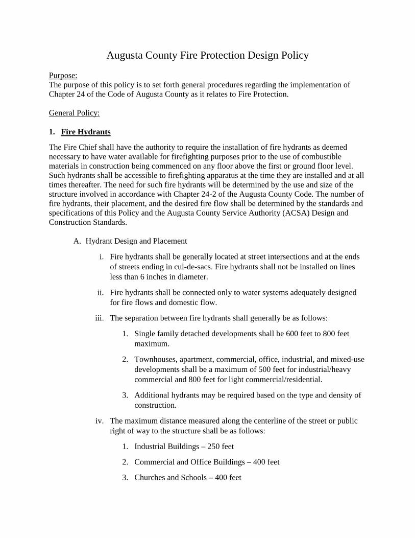
Augusta County Fire Protection Design Policy Purpose: The purpose of this policy is to set forth general procedures regarding the implementation of Chapter 24 of the Code of Augusta County as it relates to Fire Protection. General Policy: 1. Fire Hydrants
The Fire Chief shall have the authority to require the installation of fire hydrants as deemed necessary to have water available for firefighting purposes prior to the use of combustible materials in construction being commenced on any floor above the first or ground floor level. Such hydrants shall be accessible to firefighting apparatus at the time they are installed and at all times thereafter. The need for such fire hydrants will be determined by the use and size of the structure involved in accordance with Chapter 24-2 of the Augusta County Code. The number of fire hydrants, their placement, and the desired fire flow shall be determined by the standards and specifications of this Policy and the Augusta County Service Authority (ACSA) Design and Construction Standards.
A. Hydrant Design and Placement
i. Fire hydrants shall be generally located at street intersections and at the ends of streets ending in cul-de-sacs. Fire hydrants shall not be installed on lines less than 6 inches in diameter.
ii. Fire hydrants shall be connected only to water systems adequately designed for fire flows and domestic flow.
iii. The separation between fire hydrants shall generally be as follows:
1. Single family detached developments shall be 600 feet to 800 feet maximum.
2. Townhouses, apartment, commercial, office, industrial, and mixed-use developments shall be a maximum of 500 feet for industrial/heavy commercial and 800 feet for light commercial/residential.
3. Additional hydrants may be required based on the type and density of construction.
iv. The maximum distance measured along the centerline of the street or public right of way to the structure shall be as follows:
1. Industrial Buildings – 250 feet
2. Commercial and Office Buildings – 400 feet
3. Churches and Schools – 400 feet
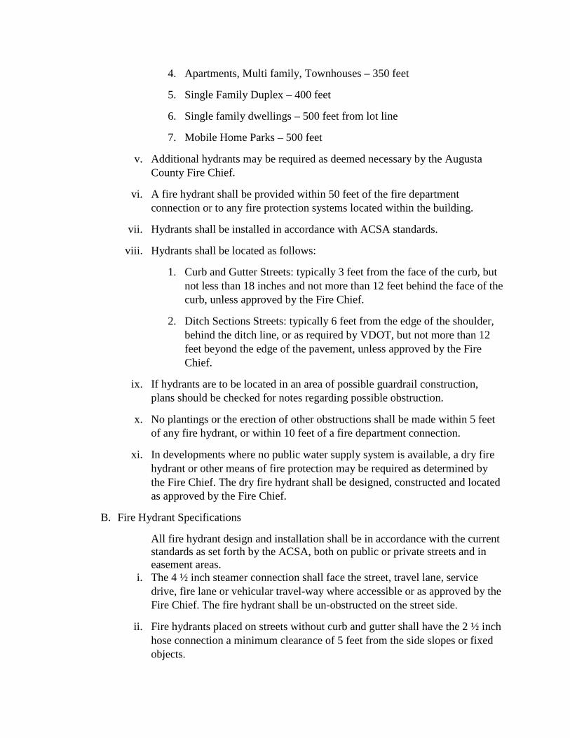
4. Apartments, Multi family, Townhouses – 350 feet
5. Single Family Duplex – 400 feet
6. Single family dwellings – 500 feet from lot line
7. Mobile Home Parks – 500 feet
v. Additional hydrants may be required as deemed necessary by the Augusta County Fire Chief.
vi. A fire hydrant shall be provided within 50 feet of the fire department connection or to any fire protection systems located within the building.
vii. Hydrants shall be installed in accordance with ACSA standards.
viii. Hydrants shall be located as follows:
1. Curb and Gutter Streets: typically 3 feet from the face of the curb, but not less than 18 inches and not more than 12 feet behind the face of the curb, unless approved by the Fire Chief.
2. Ditch Sections Streets: typically 6 feet from the edge of the shoulder, behind the ditch line, or as required by VDOT, but not more than 12 feet beyond the edge of the pavement, unless approved by the Fire Chief.
ix. If hydrants are to be located in an area of possible guardrail construction, plans should be checked for notes regarding possible obstruction.
x. No plantings or the erection of other obstructions shall be made within 5 feet of any fire hydrant, or within 10 feet of a fire department connection.
xi. In developments where no public water supply system is available, a dry fire hydrant or other means of fire protection may be required as determined by the Fire Chief. The dry fire hydrant shall be designed, constructed and located as approved by the Fire Chief.
B. Fire Hydrant Specifications
All fire hydrant design and installation shall be in accordance with the current standards as set forth by the ACSA, both on public or private streets and in easement areas.
i. The 4 ½ inch steamer connection shall face the street, travel lane, service drive, fire lane or vehicular travel-way where accessible or as approved by the Fire Chief. The fire hydrant shall be un-obstructed on the street side.
ii. Fire hydrants placed on streets without curb and gutter shall have the 2 ½ inch hose connection a minimum clearance of 5 feet from the side slopes or fixed objects.
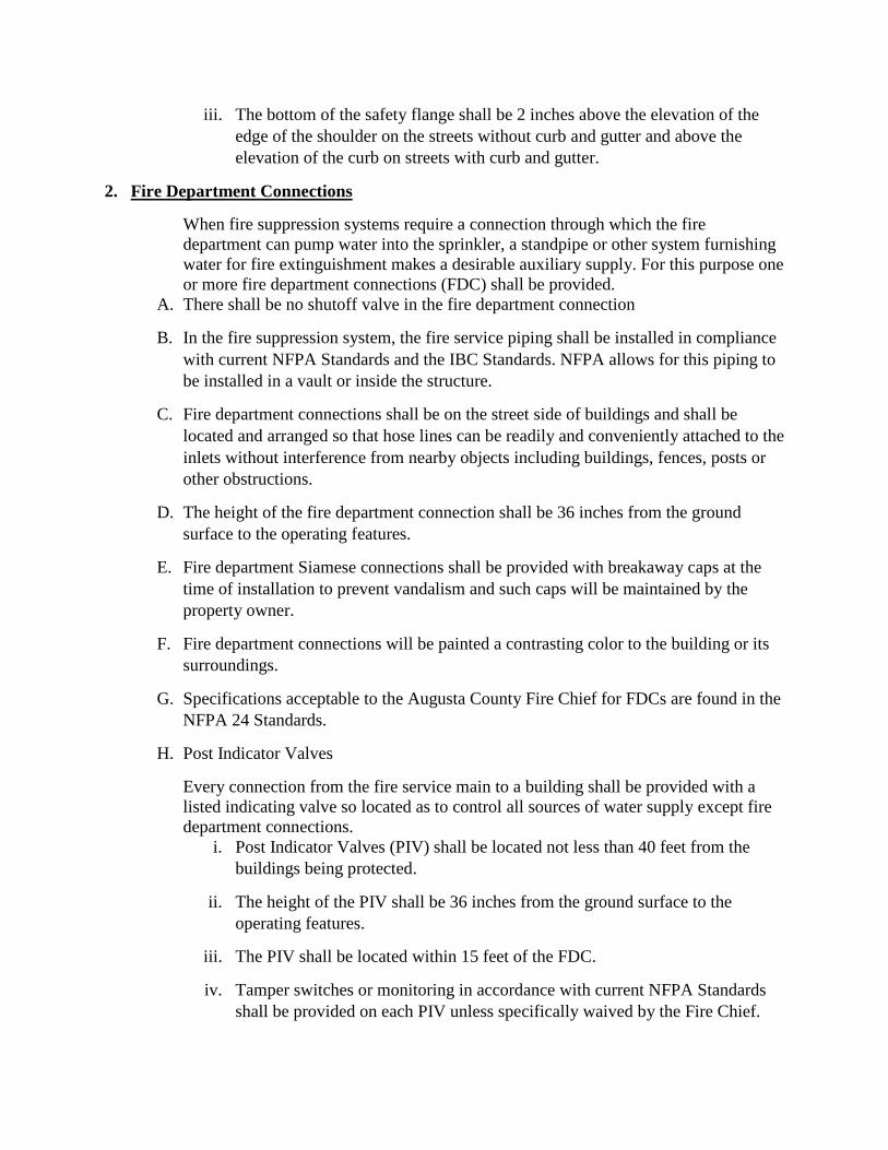
iii. The bottom of the safety flange shall be 2 inches above the elevation of the edge of the shoulder on the streets without curb and gutter and above the elevation of the curb on streets with curb and gutter.
2. Fire Department Connections
When fire suppression systems require a connection through which the fire department can pump water into the sprinkler, a standpipe or other system furnishing water for fire extinguishment makes a desirable auxiliary supply. For this purpose one or more fire department connections (FDC) shall be provided.
A. There shall be no shutoff valve in the fire department connection
B. In the fire suppression system, the fire service piping shall be installed in compliance with current NFPA Standards and the IBC Standards. NFPA allows for this piping to be installed in a vault or inside the structure.
C. Fire department connections shall be on the street side of buildings and shall be located and arranged so that hose lines can be readily and conveniently attached to the inlets without interference from nearby objects including buildings, fences, posts or other obstructions.
D. The height of the fire department connection shall be 36 inches from the ground surface to the operating features.
E. Fire department Siamese connections shall be provided with breakaway caps at the time of installation to prevent vandalism and such caps will be maintained by the property owner.
F. Fire department connections will be painted a contrasting color to the building or its surroundings.
G. Specifications acceptable to the Augusta County Fire Chief for FDCs are found in the NFPA 24 Standards.
H. Post Indicator Valves
Every connection from the fire service main to a building shall be provided with a listed indicating valve so located as to control all sources of water supply except fire department connections.
i. Post Indicator Valves (PIV) shall be located not less than 40 feet from the buildings being protected.
ii. The height of the PIV shall be 36 inches from the ground surface to the operating features.
iii. The PIV shall be located within 15 feet of the FDC.
iv. Tamper switches or monitoring in accordance with current NFPA Standards shall be provided on each PIV unless specifically waived by the Fire Chief.

v. A PIV is not required in applications where tamper switches are provided on the outside screw and yoke (OS&Y) valves located within the building.
vi. Specifications acceptable to the Augusta County Fire Chief for PIVs are found in the NFPA 24 Standards.

APPENDIX 3Rules and Regulations for Waste Water Discharge
1
SECTION 1. INTRODUCTION 1.1 Purpose These regulations set the requirements of the Augusta County Service Authority with regard
to discharges into publicly owned wastewater facilities and systems of the Augusta County Service Authority. The regulations are structured to comply with the Clean Water Act of 1972 as amended, the United States Environmental Protection Agency Pretreatment Regulations, Title 40 CFR (Part 403), State Regulation VR 680-14-10, Department of Environmental Quality, Augusta County Code (Chapter 24, Article III) and other applicable State or Federal laws. Compliance with these Rules and Regulations do not relieve any user from complying with other requirements of the local, State or Federal Government.
1.2 Objectives To prevent the introduction of pollutants into a wastewater facility and/or system of the
Augusta County Service Authority which will interfere with the operation of the system, contaminate resulting sludge or lead to a violation of the VPDES Permit requirement.
To prevent the introduction of pollutants into a wastewater facility and/or system of the
Augusta County Service Authority which will pass through the system, inadequately treated, into receiving waters or the atmosphere or be incompatible with the system.
To allow the Augusta County Service Authority to produce a high quality effluent and
sludge to meet all requirements of State and Federal Regulations. 1.3 Severability The provisions of these Rules and Regulations are severable that is if any provision,
paragraph, word, section or article of the Rules and Regulations is invalidated by any court of competent jurisdiction, the remaining provisions, paragraphs, words, sections, and chapters shall not be affected and shall continue in full force and effect.
1.4 Conflict All rules and regulations and parts of rules and regulations inconsistent or conflicting with
any part of the Rules and Regulations are hereby repealed to the extent of such inconsistency or conflict.
2
1.5 Incorporation of Federal Regulations 1. The following Federal Regulations are hereby incorporated by reference: a. 40 CFR Section 403.6 (a)-(f) (2003) - National Pretreatment Standards:
Categorical Standards. b. 40 CFR Section 403.7 (2003) - Removal Credits. c. 40 CFR Section 403.8 (b)-(e) (2003) - POTW Pretreatment Program
development and implementation by POTW. d. 40 CFR Part 136 (2003) - Guidelines for establishing test procedures for the
analysis of pollutants. e. 40 CFR Section 403.13 (2003) - Variance from Categorical Pretreatment
Standards for Fundamentally Different Factors (FDF). f. 40 CFR Section 403.15 (2003) - Net/Gross Calculations. g. 40 CFR Section 403.17 (2003) - By-Pass. h. 40 CFR Section 403.18 (2003) - Modifications to the POTW's
Pretreatment Program. i. These National Categorical Pretreatment Standards: (1). Dairy Products Processing – 40 CFR Part 405 (2003) (2). Grain Mills – 40 CFR Part 406 (2003) (3). Canned and Preserved Fruits and Vegetables – 40 CFR Part 407
(2003) (4). Canned and Preserved Seafood Processing – 40 CFR Part 408
(2003) (5). Sugar Processing – 40 CFR Part 409 (2003) (6). Textile Mills – 40 CFR Part 410 (2003) (7). Cement Manufacturing – 40 CFR Part 411 (2003_ (8). Concentrated Animal Feeding Operations (CAFO) – 40 CFR Part
412 (2003) (9). Electroplating – 40 CFR Part 413 (2003) (10). Organic Chemicals, Plastics and Synthetic Fibers – 40 CFR Part 414
(2003) (11). Inorganic Chemicals Manufacturing – 40 CFR Part 415 (2003) (12). Soap and Detergent Manufacturing – 40 CFR Part 417 (2003) (13). Fertilizer Manufacturing – 40 CFR Part 418 (2003) (14). Petroleum Refining – 40 CFR Part 419 (2003) (15). Iron and Steel Manufacturing – 40 CFR Part 420 (2003) (16). Nonferrous Metals Manufacturing – 40 CFR Part 421 (2003) (17). Phosphate Manufacturing – 40 CFR Part 422 (2003) (18). Steam Electric Power Generation – 40 CFR Part 423 (2003) (19). Ferroalloy Manufacturing – 40 CFR Part 424 (2003) (20). Leather Tanning and Finishing – 40 CFR Part 425 (2003) (21). Glass Manufacturing – 40 CFR Part 426 (2003) (22). Asbestos Manufacturing – 40 CFR Part 427 (2003)
3
(23). Rubber Manufacturing – 40 CFR Part 428 (2003) (24). Timber Products Processing – 40 CFR Part 429 (2003) (25). Pulp, Paper, and Paperboard – 40 CFR Part 430 (2003) (26). Meat Products – 40 CFR Part 432 (2003) (27). Metal Finishing – 40 CFR Part 433 (2003) (28). Coal Mining – 40 CFT Part 434 (2003) (29). Oil and Gas Extraction – 40 CFR Part 435 (2003) (30). Mineral Mining and Processing – 40 CFR Part 436 (2003) (31). Centralized Waste Treatment – 40 CFR Part 437 (2003) (32). Metal Products and Machinery – 40 CFR Part 438 (2003) (33). Pharmaceutical Manufacturing – 40 CFR Part 439 (2003) (34). Ore Mining and Dressing – 40 CFR Part 440 (2003) (35). Transportation Equipment Cleaning – 40 CFR Part 442 (2003) (36). Paving and Roofing Materials (tars and asphalt) – 40 CFR 443
(2003) (37). Waste Combustors – 40 CFR Part 444 (2003) (38). Landfills – 40 CFR Part 445 (2003) (39). Paint Formulating – 40 CFR Part 446 (2003) (40). Ink Formulating – 40 CFR Part 447 (2003) (41). Gum and Wood Chemicals Manufacturing – 40 CFR Part 454
(2003) (42). Pesticide Chemicals – 40 CFR Part 455 (2003) (43). Explosives Manufacturing – 40 CFR Part 457 (2003) (44). Carbon Black Manufacturing – 40 CFR Part 458 (2003) (45). Photographic – 40 CFR Part 459 (2003) (46). Hospitals – 40 CFR Part 460 (2003) (47). Battery Manufacturing – 40 CFR Part 461 (2003) (48). Plastics Molding and Forming – 40 CFR Part 463 (2003) (49). Metal Molding and Casting – 40 CFR Part 464 (2003) (50). Coil Coating – 40 CFR Part 465 (2003) (51). Porcelain Enameling – 40 CFR Part 466 (2003) (52). Aluminum Forming – 40 CFR Part 467 (2003) (53). Copper Forming – 40 CFR Part 468 (2003) (54). Electrical and Electronic Components – 40 CFR Part 469 (2003) (55). Nonferrous Metals Forming and Metal Powders – 40 CFR Part 471
(2003). 2. The Authority shall adopt any future changes, deletions and amendments to those
Federal Regulations cited above unless the Approval Authority undertakes a rulemaking to adopt something more stringent.
4
SECTION 2 DEFINITIONS Unless the context specifically indicates otherwise, the following words, terms, or phrases used in the Rules and Regulations shall be as defined in this section: 1) APPROVAL AUTHORITY: Means the Executive Director or Director of the Department
of Environmental Quality 2) AUTHORITY: Augusta County Service Authority 3) BASELINE MONITORING REPORT: A permit application prepared by Industrial
Users subject to categorical Pretreatment Standards. 4) BEST MANAGEMENT PRACTICE (BMP): A practice, or combination of practices,
which are low in cost, are applicable to broad categories of industry, and are determined to be an effective, practicable means of preventing or reducing the release of toxic and hazardous pollutants form spills, leaks, treatment and manufacturing processes. BMPs may be used as a control mechanism and shall be enforceable in accordance with these Regulations.
5) BI-MONTHLY: Once every other month. 6) BI-WEEKLY: Once every other week. 7) BLOWDOWN: The removal of accumulated solids in boilers to prevent plugging of
boiler tubes and steam lines. In cooling towers, blowdown is used to reduce the amount of dissolved salts in the recirculated cooling water.
8) BOARD: The Board of Directors of the Augusta County Service Authority. 9) B.O.D.: (Biochemical Oxygen Demand) - The laboratory determination of the quantity of
oxygen by weight, expressed in milligrams per liter, utilized in the biochemical oxidation of organic matter under standard laboratory conditions in five (5) days at 20 degrees C. The laboratory determination shall be made in accordance with the procedures set forth in 40 CFR Part 136.
10) BYPASS: Means the intentional diversion of wastes from any portion of a treatment
facility.
5
11) CATEGORICAL PRETREATMENT STANDARDS: Pollutant discharge limits
promulgated by the EPA in accordance with 33 USC 1317 Section 307(b) and (c) of the Clean Water Act.
12) C. O. D.: (Chemical Oxygen Demand) - The laboratory determination of the oxygen
equivalent expressed in milligrams per liter of that portion of the organic matter that is susceptible to oxidation by the standard dichromate reflux method. The laboratory determination shall be in accordance with procedures set forth in "Standard Methods".
13) COMPATIBLE POLLUTANT: Biochemical oxygen demand, suspended solids,
unoxidized nitrogen, chemical oxygen demand, phosphorus, turbidity, pH, and fecal coliform bacteria, plus additional pollutants identified in the Authority's Virginia Pollutant Discharge Elimination System (VPDES) permit, if the wastewater treatment facility to which the pollutant is discharged was designed to treat such pollutants, and in fact, does remove such pollutants to a substantial degree.
14) COMPOSITE WASTEWATER SAMPLE: A combination of individual samples of
wastewater taken at selected intervals for some specified period, to minimize the effect of the variability of individual samples. Individual samples may have equal volume or may be roughly proportioned to the flow at time of sampling.
15) CONTROL AUTHORITY: The Public Owned Treatment Works (POTW) if the
POTW's submission for its pretreatment program has been approved by the Approval Authority, or the Approval Authority if the submission has not been approved.
16) COOLING WATER: 1) Noncontact: Water used for cooling purposes only, which has no direct contact with
any raw material, intermediate, or final product. 2) Contact: Water used for cooling purposes only, which may become contaminated by
direct contact with process materials and/or wastewater. 17) COUNTY: County of Augusta 18) DAILY MAXIMUM: The maximum allowable discharge of pollutant during a calendar
day. Where daily maximum limitations are expressed in units of mass, the daily discharge is the total mass discharged over the course of the day. Where daily maximum limits are expressed in terms of concentration, the daily discharge is the arithmetic average measurement of the pollutant derived from all measurements taken that day.
19) DEQ: Virginia Department of Environmental Quality
6
20) DILUTION WASTESTREAM: Domestic wastewater, boiler/tower blowdown, non-contact cooling water (unless regulated by the categorical pretreatment standards).
21) DOMESTIC SEWAGE, DOMESTIC WASTE: Waterborne wastes normally
discharging from the sanitary conveniences of dwellings (including apartment houses and hotels), office buildings, factories and institutions, free from storm surface water and industrial wastes.
22) DULY AUTHORIZED REPRESENTATIVE OF THE INDUSTRIAL USER: 1) For Permit Applications, a Duly Authorized Representative may be: a) By a principal executive officer of at least the level of vice-president for a
corporation b) By a general partner or the proprietor for a partnership or sole proprietorship
2) All other correspondence, reports and self-monitoring reports shall be signed by either a person described above or by a duly authorized representative of that person if:
a) The Authorization is made in writing by a person described above; or b) The Authorization specified either an individual or a position having
responsibility for the overall operation of the regulated facility or activity, such as the position of plant manager, superintendent, or position of equivalent responsibility.
23) EFFLUENT: Wastewater flowing out of any facility designed to treat, convey or retain
wastewater. 24) ENGINEER: The word "Engineer" shall refer to the Authority Engineer, the Authority's
Consulting Engineer, or their duly authorized representatives. 25) ENVIRONMENTAL PROTECTION AGENCY (U.S. EPA): The United States
Environmental Protection Agency, or where appropriate, the term may also be used as a designation for the Administrator or other duly authorized official of said agency.
26) GARBAGE: Solid wastes and residue from the preparation, cooking and dispensing of
food, and from the handling, storage and sale of food products and produce. 27) GRAB WASTEWATER SAMPLE: An individual sample collected in less than 15
minutes, without regard for flow or time.
7
28) HOLDING TANK WASTE: Any waste from holding tanks, such as, but not limited to, industrial waste, chemical toilets, campers, trailers, septic tanks, and vacuum pump tank trucks. These wastes are to be discharged at a wastewater treatment facility equipped to handle such waste and not into a public sewer.
29) INCOMPATIBLE POLLUTANT: Any pollutant which is not a compatible pollutant as
defined in the Rules and Regulations. 30) INDUSTRIAL USER (IU), USER: Any source of non-domestic discharge to a POTW. 31) INDUSTRIAL WASTES, NON-DOMESTIC DISCHARGE: Any non-domestic waste. 32) INDUSTRIAL WASTE PROCESS WASTEWATER: (1) Shall include wastewater from any producing, manufacturing, processing or other
operations in which the wastewater discharged has come into direct contact with or results from the intermediate product, finished product, by-product or waste product and is not otherwise classified as domestic wastewater, dilution waste stream or unpolluted water.
(2) Shall not include any industrial or commercial user (i.e., restaurants, car washes, etc.)
who discharges only domestic or dilution wastewater and does not have a reasonable potential to affect the collection/treatment system.
33) INSPECTOR: A person authorized by the Authority to inspect wastewater generation,
conveyance, processing, pretreatment and disposal facilities. 34) INSTANTANEOUS MAXIMUM CONCENTRATION: The maximum concentration
allowed in any single grab sample. 35) INTERFERENCE: A discharge which alone or in conjunction with a discharge or
discharges from other sources, both: (1) inhibits or disrupts the POTW, its treatment process or operations, or its sludge
processes, use or disposal; and (2) therefore causes a violation of any requirement of the POTW's VPDES permit
(including an increase in the magnitude or duration of a violation) or of the prevention of the sludge use or disposal in compliance with the following statutory provisions and regulations or permits issued thereunder (or more stringent State or Local regulations): Section 405 of the Clean Water Act, the Solid Waste Disposal Act (SWDA), (including Title II, more commonly referred to as the Resource Conservation and Recovery Act (RCRA) and including State Regulations contained in any State sludge management plan prepared pursuant to Subtitle D of the SWDA), the Clean Air Act, the Toxic Substances Control Act, the Marine Protection, Research, and Sanctuaries Act (40 CFR 403.3), and the Virginia Sewerage Regulations.
8
36) MG/L: abbreviation for milligrams per liter, a mass to volume ratio. 37) MONTHLY AVERAGE: The arithmetic mean of the values for effluent samples
collected over a period of 30 consecutive days. 38) NATIONAL PRETREATMENT STANDARD: Means any regulation containing
pollutant discharge limits promulgated by the EPA in accordance with Section 307 (b) and (c) of the Clean Water Act, which applies to Industrial Users. This term includes general and prohibition discharge limits established pursuant to Section 403.5.
39) NEW SOURCE: Means any building, structure, facility, or installation from which there is
or may be a discharge of pollutants, the construction of which commenced after the publication of proposed Pretreatment Standards under Section 306 of the Clean Water Act which will be applicable to such source if such standards are thereafter promulgated in accordance with that section, within 120 days of their proposal. The term "new source" shall have the same meaning as provided in 40 CFR Section 403.3(k) (1989)
40) NON-DOMESTIC DISCHARGE, NON-DOMESTIC WASTE: Any waste other than
domestic waste. 41) PASS THROUGH: Means a discharge which exits the POTW into waters of the United
States in quantities or concentrations which alone or in conjunction with a discharge or discharges from other sources, is a cause of a violation of any requirement of the POTW's VPDES Permit (including an increase in the magnitude or duration of a violation).
42) PERMIT: An Industrial Wastewater Discharge Permit issued pursuant to the Rules and
Regulations. 43) PERMITTEE, PERMITTED INDUSTRIAL USER: A user to whom an Industrial
Wastewater Discharge Permit (Appendix B) has been granted by the Authority. 44) pH: The logarithm (base 10) of the reciprocal of the hydrogen ion concentration. 45) POLLUTANT: A substance which, when present in a sufficient concentration and under
certain conditions, can cause pollution either singularly or in combination with other substances.
46) POTW: Public Owned Treatment Works 47) PRETREATMENT: Application of physical, chemical and/or biological processes to
reduce the amount of pollutants in or alter the nature of the pollutant properties in a wastewater prior to discharging such wastewater in the wastewater treatment system.
9
48) PRETREATMENT STANDARDS: All applicable rules and regulations implementing
Section 307 of the Federal Act, as well as any nonconflicting State or local standards. In cases of conflicting standards or regulations, the more stringent thereof shall be applied.
49) PUBLIC SEWER: Either sanitary or storm sewer in which all owners of abutting
properties shall have equal rights and is controlled by public authority. 50) RULES AND REGULATIONS: the Augusta County Service Authority's Rules and
Regulations for Wastewater Discharge. 51) SANITARY SEWER: A sewer which carries sewage and to which storm, surface and
ground waters are not intentionally admitted. 52) SEPTIC TANK WASTES: Wastewater from residential septic tanks and porta-john
wastes. 53) SEWAGE: A combination of water-carried waste from residential, commercial,
institutional and industrial establishments, together with such unintentional ground, surface and storm waters as may be present.
54) SEWER: A pipe or conduit used to collect and carry away sewage or storm water run off
from the generating source to sewage treatment plants or receiving streams. 55) SHALL AND MAY: "Shall" wherever used in the Rules and Regulations will be
interpreted in its mandatory sense; "may" is permissive. 56) SIGNIFICANT INDUSTRIAL USER: Is a wastewater source that either: 1) is a categorical industry under the Federal Regulation; or 2) has a flow of 25,000 gallons or more per average workday of process wastewater to
the POTW (excluding sanitary, noncontact cooling and boiler blowdown wastewaters); or
3) has a process flow which makes up five percent or more of the average dry weather hydraulic or organic capacity of the POTW treatment plant receiving the waste; or
4) has in its waste a toxic pollutant in toxic amounts; or 5) has significant impact, either singly or in combination with other contributing
industries, on the treatment works or on the quality of its effluent; or 6) has a reasonable potential for adversely affecting the POTW's operation or for
violating any pretreatment standard or requirement.
10
57) SIGNIFICANT NON-COMPLIANCE (SNC): Violations which meet one or more of
the following criteria: 1) Violations of wastewater discharge limits. a) Chronic violations. Sixty-six percent or more of the measurements exceed
the same daily maximum limit or the same average limit in a 6-month period (any magnitude of exceedance).
b) Technical Review Criteria (TRC) violations. Thirty three percent or more of
the measurements in a 6-month period equal or exceeds the product of the daily maximum limit or the average limit multiplied by the applicable TRC.
There are two groups of TRCs: Group I for conventional pollutants TRC = 1.4 (BOD, TSS, fats, oils and grease) Group II for all other pollutants TRC = 1.2 c) Any other violation(s) of an effluent limit (average or daily maximum) that
the POTW believes has caused, alone or in combination with other discharges, interference (e.g. slug load), pass through or sludge contamination; or endangered the health of the sewage treatment personnel or the public.
d) Any discharge of a pollutant that has caused imminent endangerment to
human health/welfare or to the environment and has resulted in the POTW’s exercise of its emergency authority to halt or prevent such a discharge.
e) Failure to meet, within 90 days after the scheduled date, a compliance
schedule milestone contained in an Industrial Wastewater Discharge Permit, Administrative Compliance Order, or any other enforcement order for starting construction, completing construction, or attaining final compliance.
f) Failure to provide, within 30 days after the due date, required reports such as
baseline monitoring reports, 90-day compliance reports, periodic self-monitoring reports, and reports on compliance with compliance schedules.
g) Failure to accurately report noncompliance.
11
h) Any other violation or group of violations which the Authority determines
will adversely affect the operation or implementation of the local pretreatment program.
2. Violations of compliance schedule milestones, contained in a local control
mechanism or enforcement order, for starting construction, completing construction and attaining final compliance by 90 days or more after the schedule date.
3. Failure to provide reports for compliance schedules, self monitoring data, or
categorical standards (baseline monitoring reports, 90 day compliance reports and periodic reports) within 30 days from the due date.
4. Failure to accurately report non-compliance. 5. Any other violation or group of violations that the POTW considers to be
significant. 58) SLUG LOAD: Any discharge of water, sewage or industrial waste which in concentration
of any given constituent or in quantity of flow exceeds for any period of duration longer than fifteen (15) minutes more than five (5) times the average twenty-four (24) hour concentration of flows during the normal operation.
59) STANDARD METHOD: The most current edition of Standard Methods for the
Examination of Water and Wastewater, published by the American Public Health Association, the American Water Works Association and the Water Pollution Control Federation.
60) STATE: The Commonwealth of Virginia 61) SUSPENDED SOLIDS: Solids that either float on the surface of, or are in suspension in,
water, wastewater, or other liquids, and which are removable by laboratory filtering. Quantitative determination of suspended solids shall be made in accordance with procedures set forth in 40 CFR Part 136.
62) TOXIC: Any pollutant or combination of pollutants listed as toxic in regulations
promulgated by the Administrator of the U.S. EPA under the provision of Section 307 (a) of the Federal Act, or other accepted acts.
63) UNPOLLUTED WATER: Not containing any pollutants limited or prohibited by the
effluent standard established in the Authority’s VPDES permit or water whose discharge will not cause any violation of receiving water quality standards.
12
64) UPSET: Means an exceptional incident in which there is unintentional and temporary
noncompliance with technology based permit effluent limitations because of factors beyond the reasonable control of the permittee, excluding such factors as operational error, improperly designed or inadequate treatment facilities, or improper operation and maintenance or lack thereof.
65) USER: See industrial user. 66) VDH: Virginia Department of Health 67) VIRGINIA POLLUTANT DISCHARGE ELIMINATION SYSTEM (VPDES): The
program for issuing, conditioning and denying permits known as VPDES Permits for the discharge of pollutants from point sources, pursuant to Section 402 of the Federal Clean Water Act.
68) WASTEWATER: See sewage 69) WASTEWATER TREATMENT FACILITY: A plant operated by the Authority under
conditions prescribed in a VPDES permit system. It has devices, facilities, structures, equipment or works owned or used by the Authority for the purpose of storage, treatment, recycling and reclamation of wastewater. This includes elements essential to provide a reliable recycled supply such as standby treatment units and clear well facilities and any works, including site acquisition of land that will be an integral part of the treatment process or is used for ultimate disposal of residues resulting from such treatment.
70) WEEKLY AVERAGE: The arithmetic mean of the values for effluent samples collected
over a period of seven consecutive days.
13
SECTION 3. PERMITTING OF INDUSTRIAL DISCHARGERS 3.1 Permits Required Any user desiring to discharge into the public sanitary sewer system shall first make
application and obtain an Industrial Wastewater Discharge Permit (Appendix B), or the Authority's written permission to discharge, prior to any discharge to the sewer system. Any existing users who are presently discharging industrial waste to the public sanitary sewer system shall submit a completed application for a permit within sixty (60) days and obtain the Discharge Permit, or the Authority's written permission to discharge, within one-hundred and eighty (180) days of the effective date of the Rules and Regulations. All industrial users must reapply within ninety (90) days prior to the expiration of their Permit or written permission to discharge.
3.2 Permit Application Requirements All industrial users seeking a permit shall complete and file with the Authority and/or its
authorized agents a completed application form, Appendix A, containing the following information where appropriate:
1. Name, address, telephone number, and location (if different from address)
and type of permit application (either existing or proposed). 2. SIC number according to the Standard Industrial Classification Manual
1987. 3. Estimated volume of wastewater to be discharged. 4. Wastewater constituents and characteristics including, but not limited to,
those mentioned in the Rules and Regulations as determined by a laboratory approved by the Authority.
5. Time and duration of discharge. 6. Average daily flow and 30-minute peak wastewater flow rates, including
daily, monthly and seasonal variations if any. 7. Site plans, floor plans, mechanical and plumbing plans, and details to show
all sewers and appurtenances by size, location, and elevation.
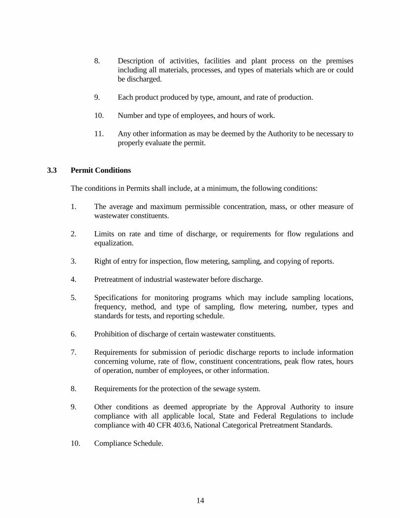
14
8. Description of activities, facilities and plant process on the premises
including all materials, processes, and types of materials which are or could be discharged.
9. Each product produced by type, amount, and rate of production. 10. Number and type of employees, and hours of work. 11. Any other information as may be deemed by the Authority to be necessary to
properly evaluate the permit. 3.3 Permit Conditions The conditions in Permits shall include, at a minimum, the following conditions: 1. The average and maximum permissible concentration, mass, or other measure of
wastewater constituents. 2. Limits on rate and time of discharge, or requirements for flow regulations and
equalization. 3. Right of entry for inspection, flow metering, sampling, and copying of reports. 4. Pretreatment of industrial wastewater before discharge. 5. Specifications for monitoring programs which may include sampling locations,
frequency, method, and type of sampling, flow metering, number, types and standards for tests, and reporting schedule.
6. Prohibition of discharge of certain wastewater constituents. 7. Requirements for submission of periodic discharge reports to include information
concerning volume, rate of flow, constituent concentrations, peak flow rates, hours of operation, number of employees, or other information.
8. Requirements for the protection of the sewage system. 9. Other conditions as deemed appropriate by the Approval Authority to insure
compliance with all applicable local, State and Federal Regulations to include compliance with 40 CFR 403.6, National Categorical Pretreatment Standards.
10. Compliance Schedule.
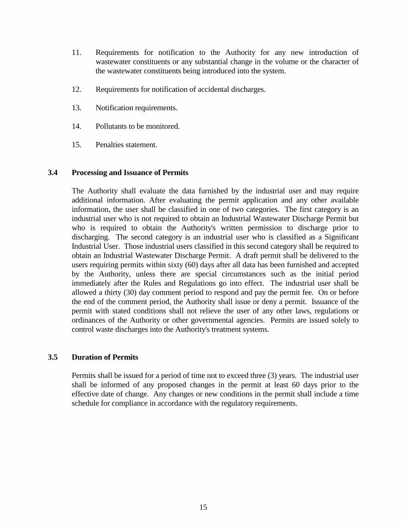
15
11. Requirements for notification to the Authority for any new introduction of wastewater constituents or any substantial change in the volume or the character of the wastewater constituents being introduced into the system.
12. Requirements for notification of accidental discharges. 13. Notification requirements. 14. Pollutants to be monitored. 15. Penalties statement. 3.4 Processing and Issuance of Permits The Authority shall evaluate the data furnished by the industrial user and may require
additional information. After evaluating the permit application and any other available information, the user shall be classified in one of two categories. The first category is an industrial user who is not required to obtain an Industrial Wastewater Discharge Permit but who is required to obtain the Authority's written permission to discharge prior to discharging. The second category is an industrial user who is classified as a Significant Industrial User. Those industrial users classified in this second category shall be required to obtain an Industrial Wastewater Discharge Permit. A draft permit shall be delivered to the users requiring permits within sixty (60) days after all data has been furnished and accepted by the Authority, unless there are special circumstances such as the initial period immediately after the Rules and Regulations go into effect. The industrial user shall be allowed a thirty (30) day comment period to respond and pay the permit fee. On or before the end of the comment period, the Authority shall issue or deny a permit. Issuance of the permit with stated conditions shall not relieve the user of any other laws, regulations or ordinances of the Authority or other governmental agencies. Permits are issued solely to control waste discharges into the Authority's treatment systems.
3.5 Duration of Permits Permits shall be issued for a period of time not to exceed three (3) years. The industrial user
shall be informed of any proposed changes in the permit at least 60 days prior to the effective date of change. Any changes or new conditions in the permit shall include a time schedule for compliance in accordance with the regulatory requirements.
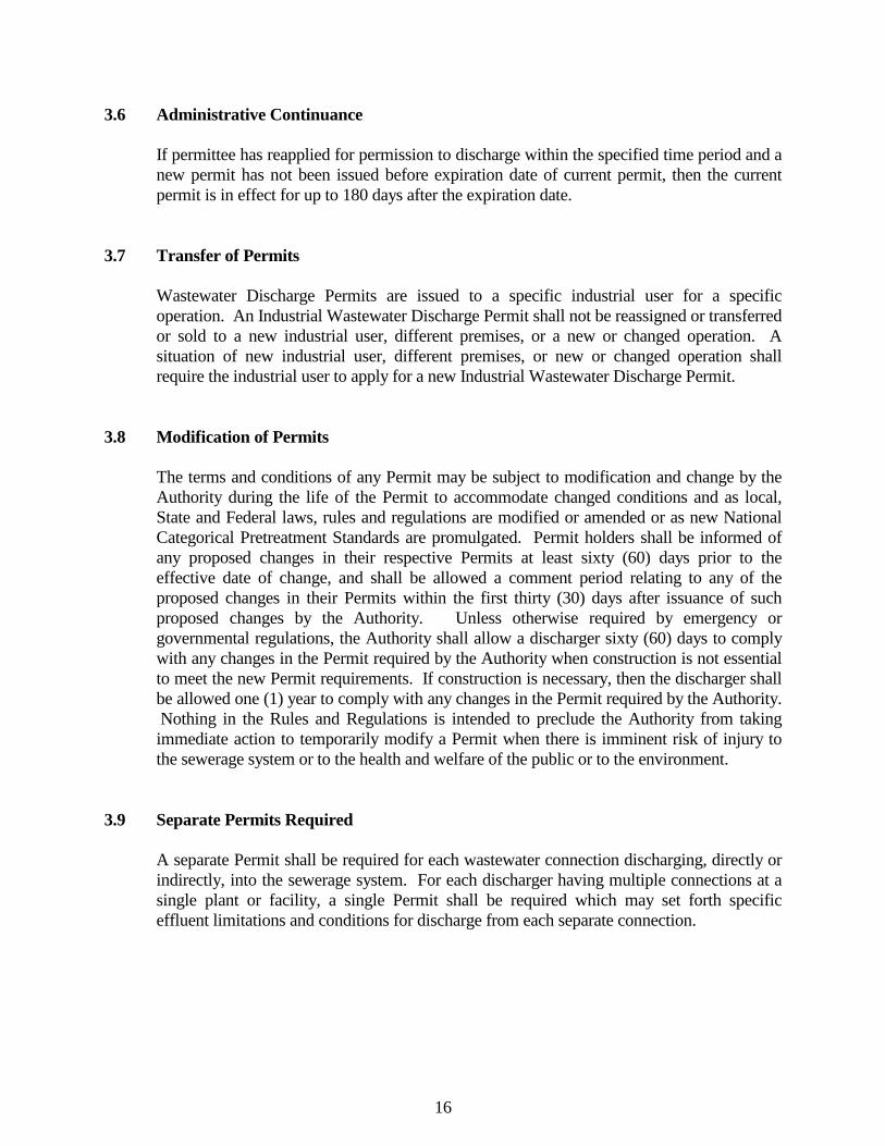
16
3.6 Administrative Continuance If permittee has reapplied for permission to discharge within the specified time period and a new permit has not been issued before expiration date of current permit, then the current permit is in effect for up to 180 days after the expiration date.
3.7 Transfer of Permits Wastewater Discharge Permits are issued to a specific industrial user for a specific
operation. An Industrial Wastewater Discharge Permit shall not be reassigned or transferred or sold to a new industrial user, different premises, or a new or changed operation. A situation of new industrial user, different premises, or new or changed operation shall require the industrial user to apply for a new Industrial Wastewater Discharge Permit.
3.8 Modification of Permits The terms and conditions of any Permit may be subject to modification and change by the
Authority during the life of the Permit to accommodate changed conditions and as local, State and Federal laws, rules and regulations are modified or amended or as new National Categorical Pretreatment Standards are promulgated. Permit holders shall be informed of any proposed changes in their respective Permits at least sixty (60) days prior to the effective date of change, and shall be allowed a comment period relating to any of the proposed changes in their Permits within the first thirty (30) days after issuance of such proposed changes by the Authority. Unless otherwise required by emergency or governmental regulations, the Authority shall allow a discharger sixty (60) days to comply with any changes in the Permit required by the Authority when construction is not essential to meet the new Permit requirements. If construction is necessary, then the discharger shall be allowed one (1) year to comply with any changes in the Permit required by the Authority. Nothing in the Rules and Regulations is intended to preclude the Authority from taking immediate action to temporarily modify a Permit when there is imminent risk of injury to the sewerage system or to the health and welfare of the public or to the environment.
3.9 Separate Permits Required A separate Permit shall be required for each wastewater connection discharging, directly or
indirectly, into the sewerage system. For each discharger having multiple connections at a single plant or facility, a single Permit shall be required which may set forth specific effluent limitations and conditions for discharge from each separate connection.
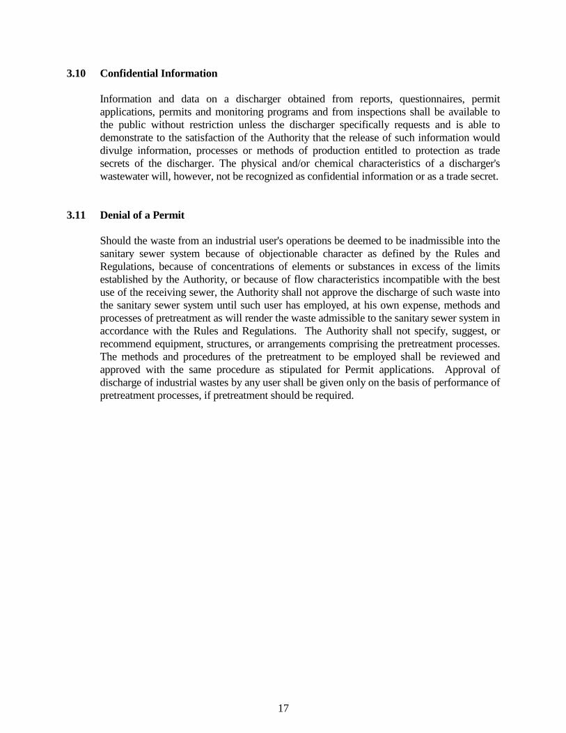
17
3.10 Confidential Information Information and data on a discharger obtained from reports, questionnaires, permit
applications, permits and monitoring programs and from inspections shall be available to the public without restriction unless the discharger specifically requests and is able to demonstrate to the satisfaction of the Authority that the release of such information would divulge information, processes or methods of production entitled to protection as trade secrets of the discharger. The physical and/or chemical characteristics of a discharger's wastewater will, however, not be recognized as confidential information or as a trade secret.
3.11 Denial of a Permit Should the waste from an industrial user's operations be deemed to be inadmissible into the
sanitary sewer system because of objectionable character as defined by the Rules and Regulations, because of concentrations of elements or substances in excess of the limits established by the Authority, or because of flow characteristics incompatible with the best use of the receiving sewer, the Authority shall not approve the discharge of such waste into the sanitary sewer system until such user has employed, at his own expense, methods and processes of pretreatment as will render the waste admissible to the sanitary sewer system in accordance with the Rules and Regulations. The Authority shall not specify, suggest, or recommend equipment, structures, or arrangements comprising the pretreatment processes. The methods and procedures of the pretreatment to be employed shall be reviewed and approved with the same procedure as stipulated for Permit applications. Approval of discharge of industrial wastes by any user shall be given only on the basis of performance of pretreatment processes, if pretreatment should be required.
18
SECTION 4 PERMIT REQUIREMENTS 4.1 General Requirements 1. Duty to Comply The permittee shall comply with all conditions of the permit. Failure to comply
with the requirements of the Rules and Regulations may be grounds for administrative action, or enforcement proceedings including civil and/or criminal penalties, injunctive relief and termination of service.
2. Duty to Mitigate The permittee shall take all reasonable steps to minimize or correct any adverse
impact on the environment resulting from noncompliance with the permit, including such accelerated or additional monitoring as necessary to determine the nature and impact of the noncomplying discharge.
3. Right of Entry The Authority may inspect the facilities of any permittee to ascertain whether the
provisions of the Rules and Regulations are being met and all requirements are being complied with. The permittee shall allow authorized Authority representatives, upon the presentation of credentials:
a. To have ready access at all reasonable times to all parts of the permittee's
premises for purposes of inspection and/or sampling in the performance of any of their duties.
b. To have access to and copy at reasonable times any records required to be
kept under the terms and conditions of the permit; c. To inspect at reasonable times any facilities, equipment (including
monitoring equipment and control equipment), practices, operations or monitoring method regulated or required in the permit; or
d. To sample or monitor at reasonable times, for the purposes of assuring
permit compliance, any substances or parameters at any location; e. Inspect any production, manufacturing, fabricating or storage area where
pollutants, regulated under the permit, could originate.
19
Where the permittee has security measures in force which would require proper
identification and clearance before entry into their premises, the user shall make necessary arrangements with their security guards so that upon presentation of suitable identification, personnel from the Authority will be permitted to enter without delay for the purposes of performing their specific responsibilities.
4. Permit Modification and Revocation The permit may be modified, revoked and reissued, or terminated in whole or in part
during its term for cause including, but not limited to, the following: a. To incorporate any new or revised Federal, State, or local pretreatment
standards or requirements; b. Material or substantial alterations or additions to the dischargers operation not
covered in the effective permit; c. A change in any condition that requires either a temporary or permanent
reduction or elimination of the authorized discharge; d. Information indicating that the permitted discharge poses a threat to the
Authority's collection and treatment systems, POTW personnel or the receiving waters;
e. Violation of any terms or conditions of the permit; f. The effluent from the wastewater treatment plant is no longer of a quality
permitted for discharge to a watercourse, and it is found that the Permittee is delivering wastes to the wastewater system that cannot be sufficiently treated or require pretreatment; or
g. The Permittee
1) discharges wastewater that is in significant non-compliance of the permit issued;
2) fails to pay user charges for public sewer services when due; 3) discharges prohibited wastes to public sewers; or 4) violates any requirement of these Rules and Regulations

20
The filing of a request by the permittee for a permit modification, revocation and
reissuance, or termination, or notification of planned changes or anticipated noncompliance, does not stay any permit conditions.
5. Property Rights The issuance of the permit does not convey any property rights in either real or
personal property, or any exclusive privileges, nor does it authorize any injury to private property or any invasion of personal rights, nor any infringement of Federal, State, or local laws or regulations.
6. Transfer of Ownership or Control Wastewater discharge permits are issued to a specific user for a specific operation
and are not assignable to another user or transferable to any other location without the prior written approval of the Augusta County Service Authority. In the event of sale, the permittee must inform the purchaser of all responsibilities and obligations under the permit.
7. Dilution The permittee shall not increase the use of potable or process water or, in any way,
attempt to dilute a discharge as a partial or complete substitute for adequate treatment to achieve compliance with the limitations contained in the permit.
8. Adverse Impact The permittee shall take all reasonable steps to minimize any adverse impact on the
receiving works resulting from noncompliance with any effluent limitations specified in the permit, including such accelerated or additional monitoring as necessary to determine the nature and impact of the non-complying discharge. The permittee shall immediately notify the Augusta County Service Authority of slug discharges, spills that may enter the public sewer, or any other significant changes in operations, wastewater characteristics and constituents.
9. Special Agreements Special agreements and arrangements between Authority and any user, unless
disapproved by the State, may be established with respect to the issuance of a permit when in the opinion of the Authority unusual or extraordinary circumstances compel special terms and conditions. In no case shall allowable discharge be in excess of National Categorical Standards or the general and specific prohibitions of 40 C.F.R. 403.5.
21
10. Pretreatment Permitted industrial users shall make wastewater acceptable under the limitations
established herein before discharging to a wastewater treatment system. Any facilities required to pretreat wastewater to meet the requirements of the Rules and Regulations shall be provided and maintained at the user's expense. Detailed plans showing the pretreatment facilities and operating and maintenance procedures shall be submitted to the Authority for review, and must be acceptable to the Authority before construction of the facility. The review of such plans and operation and maintenance procedures shall in no way relieve the permitted industrial user from the responsibility of modifying the facility, as necessary, to produce an effluent acceptable to the Authority under the provisions of the Rules and Regulations. Any subsequent changes in the pretreatment facilities or method of operations shall be reported to the Authority before their implementation. These changes shall be acceptable to the Authority.
11. Slug Discharge Control Plan Upon submission of an Application for Discharge Permit and every two years
thereafter, the Authority shall evaluate whether each Significant Industrial User needs a plan to control slug discharges. The need for a Slug Discharge Control Plan shall be evaluated based upon criteria such as the users potential for slug discharges, history of slug discharges, presence of stored chemicals, whether stored chemicals are in diked storage areas, and the proximity of floor drains to those stored chemicals.
If a Slug Discharge Control Plan is required, it shall contain at least the following
elements: a. A description of discharge practices, including nonroutine batch discharge. b. A description of stored chemicals. c. Procedures for promptly notifying the POTW of slug discharges, including any
discharge that would violate a specific prohibition under 40 CFR 403.5(b), with procedures for follow-up written notification within five days.
d. If necessary, procedures to prevent adverse impact from accidental spills,
including inspection and maintenance of storage areas, handling and transfer of materials, loading and unloading operations, control of plant site run off, worker training, building of containment structures or equipment, measures for containing toxic organic pollutants (including solvents) and/or measures and equipment for emergency response.
22
e. If necessary, follow-up practices to limit the damage suffered by the treatment
plant or the environment. The Slug Discharge Control Plan shall be signed by one of the following: 1) For a corporation: by a principal executive officer of at least the
level of vice-president. 2) For a partnership or sole proprietorship: by a general partner or the
proprietor, respectively. 3) By a duly authorized representative of one of the above. A person is
a duly authorized representative only if: a. The authorization is made in writing by a person described in
Section 4.1.11 1) or 2). b. The authorization specifies either an individual or a position
having responsibility for the overall operation of the regulated facility or activity, such as the position of plant manager, superintendent, or position of equivalent responsibility.
The Slug Control Plan shall be certified by the following statement. "I certify under penalty of law that this document and all attachments were
prepared under my direction or supervision in accordance with a system designed to assure that qualified personnel properly gathered and evaluated the information submitted. Based on my inquiry of the person or persons who managed the system, or those persons directly responsible for gathering the information, the information submitted is, to the best of my knowledge and belief, true, accurate and complete. I am aware that there are significant penalties for submitting false information, including the possibility of fines and imprisonment for knowing violations."
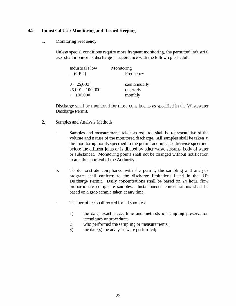
23
4.2 Industrial User Monitoring and Record Keeping 1. Monitoring Frequency Unless special conditions require more frequent monitoring, the permitted industrial
user shall monitor its discharge in accordance with the following schedule. Industrial Flow Monitoring (GPD) Frequency 0 - 25,000 semiannually 25,001 - 100,000 quarterly > 100,000 monthly Discharge shall be monitored for those constituents as specified in the Wastewater
Discharge Permit. 2. Samples and Analysis Methods a. Samples and measurements taken as required shall be representative of the
volume and nature of the monitored discharge. All samples shall be taken at the monitoring points specified in the permit and unless otherwise specified, before the effluent joins or is diluted by other waste streams, body of water or substances. Monitoring points shall not be changed without notification to and the approval of the Authority.
b. To demonstrate compliance with the permit, the sampling and analysis
program shall conform to the discharge limitations listed in the IU's Discharge Permit. Daily concentrations shall be based on 24 hour, flow proportionate composite samples. Instantaneous concentrations shall be based on a grab sample taken at any time.
c. The permittee shall record for all samples: 1) the date, exact place, time and methods of sampling preservation
techniques or procedures; 2) who performed the sampling or measurements; 3) the date(s) the analyses were performed;
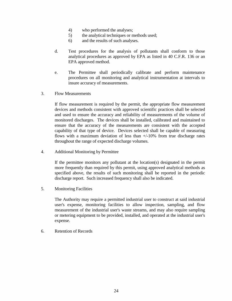
24
4) who performed the analyses; 5) the analytical techniques or methods used; 6) and the results of such analyses. d. Test procedures for the analysis of pollutants shall conform to those
analytical procedures as approved by EPA as listed in 40 C.F.R. 136 or an EPA approved method.
e. The Permittee shall periodically calibrate and perform maintenance
procedures on all monitoring and analytical instrumentation at intervals to insure accuracy of measurements.
3. Flow Measurements If flow measurement is required by the permit, the appropriate flow measurement
devices and methods consistent with approved scientific practices shall be selected and used to ensure the accuracy and reliability of measurements of the volume of monitored discharges. The devices shall be installed, calibrated and maintained to ensure that the accuracy of the measurements are consistent with the accepted capability of that type of device. Devices selected shall be capable of measuring flows with a maximum deviation of less than +/-10% from true discharge rates throughout the range of expected discharge volumes.
4. Additional Monitoring by Permittee If the permittee monitors any pollutant at the location(s) designated in the permit
more frequently than required by this permit, using approved analytical methods as specified above, the results of such monitoring shall be reported in the periodic discharge report. Such increased frequency shall also be indicated.
5. Monitoring Facilities The Authority may require a permitted industrial user to construct at said industrial
user's expense, monitoring facilities to allow inspection, sampling, and flow measurement of the industrial user's waste streams, and may also require sampling or metering equipment to be provided, installed, and operated at the industrial user's expense.
6. Retention of Records
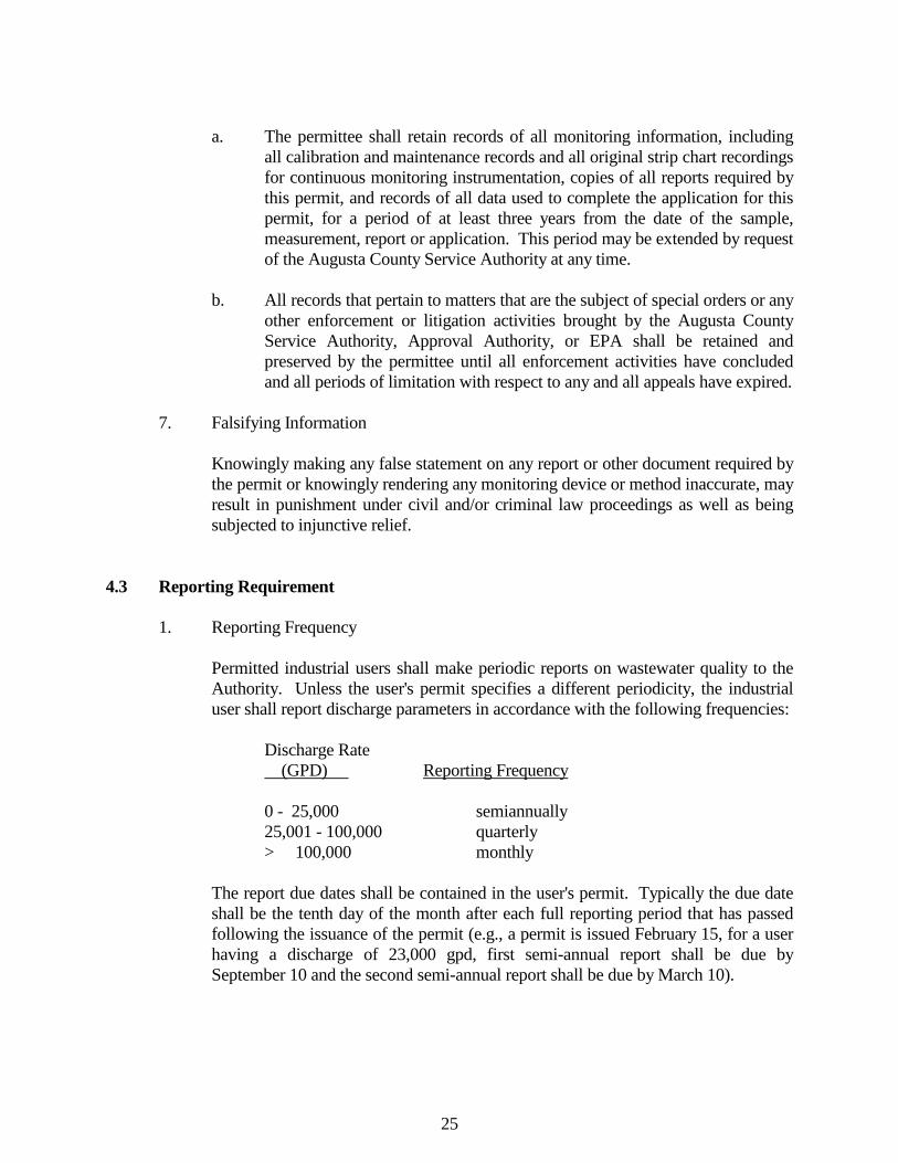
25
a. The permittee shall retain records of all monitoring information, including
all calibration and maintenance records and all original strip chart recordings for continuous monitoring instrumentation, copies of all reports required by this permit, and records of all data used to complete the application for this permit, for a period of at least three years from the date of the sample, measurement, report or application. This period may be extended by request of the Augusta County Service Authority at any time.
b. All records that pertain to matters that are the subject of special orders or any
other enforcement or litigation activities brought by the Augusta County Service Authority, Approval Authority, or EPA shall be retained and preserved by the permittee until all enforcement activities have concluded and all periods of limitation with respect to any and all appeals have expired.
7. Falsifying Information Knowingly making any false statement on any report or other document required by
the permit or knowingly rendering any monitoring device or method inaccurate, may result in punishment under civil and/or criminal law proceedings as well as being subjected to injunctive relief.
4.3 Reporting Requirement 1. Reporting Frequency Permitted industrial users shall make periodic reports on wastewater quality to the
Authority. Unless the user's permit specifies a different periodicity, the industrial user shall report discharge parameters in accordance with the following frequencies:
Discharge Rate (GPD) Reporting Frequency 0 - 25,000 semiannually 25,001 - 100,000 quarterly > 100,000 monthly The report due dates shall be contained in the user's permit. Typically the due date
shall be the tenth day of the month after each full reporting period that has passed following the issuance of the permit (e.g., a permit is issued February 15, for a user having a discharge of 23,000 gpd, first semi-annual report shall be due by September 10 and the second semi-annual report shall be due by March 10).
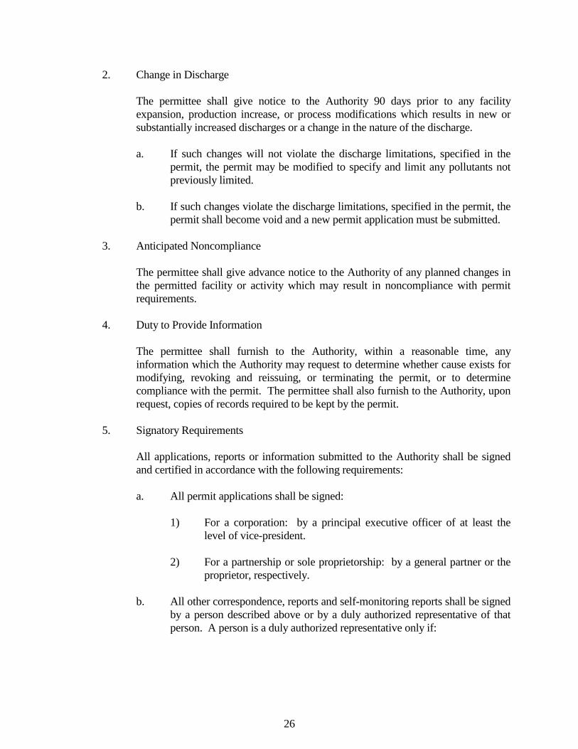
26
2. Change in Discharge The permittee shall give notice to the Authority 90 days prior to any facility
expansion, production increase, or process modifications which results in new or substantially increased discharges or a change in the nature of the discharge.
a. If such changes will not violate the discharge limitations, specified in the
permit, the permit may be modified to specify and limit any pollutants not previously limited.
b. If such changes violate the discharge limitations, specified in the permit, the
permit shall become void and a new permit application must be submitted. 3. Anticipated Noncompliance The permittee shall give advance notice to the Authority of any planned changes in
the permitted facility or activity which may result in noncompliance with permit requirements.
4. Duty to Provide Information The permittee shall furnish to the Authority, within a reasonable time, any
information which the Authority may request to determine whether cause exists for modifying, revoking and reissuing, or terminating the permit, or to determine compliance with the permit. The permittee shall also furnish to the Authority, upon request, copies of records required to be kept by the permit.
5. Signatory Requirements All applications, reports or information submitted to the Authority shall be signed
and certified in accordance with the following requirements: a. All permit applications shall be signed: 1) For a corporation: by a principal executive officer of at least the
level of vice-president. 2) For a partnership or sole proprietorship: by a general partner or the
proprietor, respectively. b. All other correspondence, reports and self-monitoring reports shall be signed
by a person described above or by a duly authorized representative of that person. A person is a duly authorized representative only if:
27
1) The authorization is made in writing by a person described in Section 4.3.5.a.
2) The authorization specifies either an individual or a position having
responsibility for the overall operation of the regulated facility or activity, such as the position of plant manager, superintendent, or position of equivalent responsibility.
c. Certification. Any person signing a document under this section shall make
the following certification: "I certify under penalty of law that this document and all attachments were
prepared under my direction or supervision in accordance with a system designed to assure that qualified personnel properly gather and evaluate the information submitted. Based on my inquiry of the person or persons who manage the system, or those persons directly responsible for gathering the information, the information submitted is, to the best of my knowledge and belief, true, accurate and complete. I am aware that there are significant penalties for submitting false information, including the possibility of fine and imprisonment for knowing violations."
d. Any change in signatures shall be submitted to the Authority in writing
within 30 days after the change. 6. Reporting Requirements for Known Violations Other Than Accidental Discharges
or Slug Load If for any reason the Permittee does not comply with the limitations of the permit,
the Permittee shall notify the Authority immediately by telephone and follow in writing within five (5) days a description of the violations and the reason or explanation for said violations. The written notification shall also address the steps taken to assure compliance and to eliminate chance of reoccurrence. The Permittee shall resample, retest, and submit new test results within 30 days of becoming aware of violation.
7. Reporting Requirements for Industries Subject to National Categorical Standards All industrial users subject to National Categorical Standards shall submit the
following reports to the Authority.
28
a. Categorical Industries Baseline Monitoring Report (BMR) Within 180 days after the effective date of a categorical pretreatment
standard, or 180 days after the final administrative decision made upon a category determination submission under Section 7.5 of VR 680-14-01, whichever is later, existing industrial users subject to categorical pretreatment standards and currently discharging to or scheduled to discharge to a POTW shall submit to the Authority a report which contains the information listed in the following paragraphs 1. through 7. When reports containing this information have already been submitted to the Authority, the industrial user will not be required to submit this information again. New sources, and sources that become industrial users subsequent to promulgation of applicable categorical standards, shall submit to the Authority a report 90 days before commencing discharge to the POTW which contains the information listed in the following paragraphs 1. through 5. and the methods of treatment to be used in meeting applicable standards. New sources may estimate concentration, flow and production data. Required information is as follows:
1. Identifying information. The industrial user shall submit the name
and address of the facility including the name of the operator and owners;
2. Permits. The industrial user shall submit a list of any environmental
control permits held by or for the facility; 3. Description of operations. The industrial user shall submit a brief
description of the nature, average rate of production and Standard Industrial Classification (SIC) Code of the operation carried out by such industrial user. This description shall include a schematic process diagram which indicates points of discharge to the POTW from the regulated processes.
4. Flow measurement. The industrial user shall submit information
showing the measured average daily and maximum daily flow in gallons per day to the POTW from regulated process streams; and other streams as necessary to allow use of the combined waste stream formula of 40 CFR § 403.6 (e). The Authority may allow for verifiable estimates of these flows when justified by cost or feasibility consideration.
29
5. Measurement of pollutants. a) The industrial user shall identify the pretreatment standards
applicable to each regulated process; b) The industrial user shall submit the results of sampling and
analysis identifying the nature and concentration, or mass, of regulated pollutants in the discharge from each regulated process. Both daily maximum and average concentration, or mass, where required shall be reported. The sample shall be representative of daily operations;
c) A minimum of four (4) grab samples must be used for pH,
cyanide, total phenols, oil and grease, sulfide, and volatile organics. For all other pollutants, 24-hour composite samples must be obtained through flow-proportional composite sampling techniques where feasible. The Authority may waive flow-proportional composite sampling for any industrial user that demonstrates that flow-proportional sampling is infeasible. In such cases, samples may be obtained through time-proportional composite sampling techniques or through a minimum of four (4) grab samples where the industrial user demonstrates that this will provide a representative sample of the effluent being discharged.
d) The industrial user shall take a minimum of one
representative sample to compile that data necessary to comply with the requirements of this paragraph.
e) Samples shall be taken immediately downstream from
pretreatment facilities if such exist or immediately downstream from the regulated process if no pretreatment exists. If other wastewaters are mixed with the regulated wastewater prior to pretreatment the industrial user should measure the flows and concentrations necessary to allow use of the combined waste stream formula found in 40 CFR Part 403.6 (e) in order to evaluate compliance with the pretreatment standards. When an alternate concentration or mass limit has been calculated in accordance with the combined waste stream formula in 40 CFR Part 403.6(e), this adjusted limit along with supporting data shall be submitted to the Authority;
30
f) Sampling and analysis procedures shall be performed in accordance with the techniques prescribed in the current 40 CFR § 136. When 40 CFR Part 136 does not contain sampling or analytical techniques for the pollutant in question, or when the Director determines that the Part 136 sampling and analytical techniques are inappropriate for the pollutant in question, sampling and analysis shall be performed by using validated analytical methods or any other applicable sampling and analytical procedures, including procedures suggested by the POTW or other parties, approved by the EPA;
g) The Authority may allow the submission of a Baseline
Monitoring Report which utilizes only historical data so long as the data provides information sufficient to determine the need for industrial pretreatment measures;
h) The Baseline Monitoring Report shall indicate the time, date
and place, of sampling, and methods of analysis, and shall certify that such sampling and analysis is representative of normal work cycles and expected pollutant discharges to the POTW.
6. Certification. The industrial user shall submit a statement, reviewed
by an authorized representative of the industrial user, indicating whether pretreatment standards are being met on a consistent basis, and, if not, whether additional operation and maintenance and/or additional pretreatment is required for the industrial user to meet the pretreatment standards and requirements.
7. Compliance schedule. If additional pretreatment and/or operation
and maintenance are required to meet the pretreatment standards; the industrial user shall submit the shortest schedule by which the industrial user will provide such additional pretreatment and/or operation and maintenance. The completion date in this schedule shall not be later than the compliance date established for the applicable pretreatment standard.
a) When the industrial user's categorical pretreatment standard
has been modified by the combined waste stream formula regulated under 40 CFR § 403.13 and/or a Fundamentally Different Factors variance, the information required by paragraphs 4.3.8.a.6 and 7 pertain to the modified limits.
31
b) If the categorical pretreatment standard is modified by the
combined waste stream formula and/or a Fundamentally Different Factors variance after the industrial user submits the report required by paragraph 4.3.8.a, any necessary amendments to the information requested by paragraphs 4.3.8.a.6 and 7 shall be submitted by the industrial user to the Authority within 60 days after the modified limit is approved.
c) The following conditions shall apply to the schedule required
by paragraph 4.3.8.a.7 above: 1) The schedule shall contain increments of progress in
the form of dates for the commencement and completion of major events leading to the construction and operation of additional pretreatment facilities required for the industrial user to meet the applicable categorical pretreatment standards. No increment of this schedule shall exceed nine months.
2) Not later than 14 days following each date in the
schedule and the final date for compliance, the industrial user shall submit a progress report to the Authority including, at a minimum, whether or not it complied with the increment of progress to be met on that date and if not, the date on which it expects to comply with this increment of progress, the reason for delay, and the steps being taken by the industrial user to return the construction to the schedule established. In no event shall more than nine months elapse between such progress reports to the Authority.
b. Report on Compliance with Categorical Pretreatment Standard Deadline. Within 90 days following the date for final compliance with applicable
categorical pretreatment standards, or in the case of a new source following commencement of the introduction of wastewater into the POTW, any industrial user subject to pretreatment standards and requirements shall submit to the Authority a report containing the information described in paragraphs 4.3.8.a.4 through 6. Industrial users subject to production based standards must submit actual production rate data for the appropriate sampling period.
32
c. Periodic Reports on Continued Compliance. Any industrial user subject to a categorical pretreatment standard, after the
compliance date of that pretreatment standard, or, in the case of a new source, after commencement of the discharge into the POTW, shall submit to the Authority during the months of June and December, unless required more frequently in the pretreatment standard or by the Authority, a report indicating the nature and concentration of pollutants in the effluent which are limited by such categorical pretreatment standards, and a reasonable measure of the users long term production rate. If an industrial user is subject to categorical standards with only production based limits, actual average production rate data for the reporting period must be given. In addition, this report shall include a record of measurements of estimated average and maximum daily flows for the reporting period for the discharge reported in paragraph 4.3.8.a.4 except that the Authority may require more detailed reporting of flows. At the discretion of the Authority and in consideration of such factors as local high or low flow rates, holidays, budget cycles, etc., the Authority may agree to alter the months during which the above reports are to be submitted.
4.4 Operation and Maintenance of Pollution Controls 1. Proper Operation and Maintenance The permittee shall at all times properly operate and maintain all facilities and
systems of treatment and control (and related appurtenances) which are installed or used by the permittee to achieve compliance with the conditions of the permit. Proper operation and maintenance includes but is not limited to: effective performance, adequate funding, adequate operator staffing and training, and adequate laboratory and process controls, including assurance procedures. This provision requires the operation of back-up or auxiliary facilities or similar systems only when necessary to achieve compliance with the conditions of the permit.
2. Duty to Halt or Reduce Activity Upon reduction, loss, or failure of the industrial user's pre-treatment facility, the
permittee shall, to the extent necessary to maintain compliance with its permit, control production of all discharges or both until operation of the pre-treatment facility is restored or an alternative method of treatment is provided. This requirement applies, for example, when the primary source of power of the pre-treatment facility fails or is reduced. It shall not be a defense for a permittee in an enforcement action that it would have been necessary to halt or reduce the permitted activity in order to maintain compliance with the conditions of this permit.
33
3. Bypass of Pre-Treatment Facilities a. Bypass is prohibited unless it is unavoidable to prevent loss of life, personal
injury or severe property damage or no feasible alternatives exist. b. The permittee may allow bypass to occur which does not cause effluent
limitations to be exceeded, but only if it also is for essential maintenance or to assure efficient operation.
c. Notification of bypass: 1) Anticipated Bypass. If the permittee knows in advance of the need
for a bypass, it shall submit prior written notice, at least 10 days before the date of the bypass to the Augusta County Service Authority, P. O. Box 859, Verona, VA 24482.
2) Unanticipated bypass. The permittee shall immediately notify the
Augusta County Service Authority and submit a written notice to the POTW within 24 hours of becoming aware of the bypass.
3) Notification of bypass shall contain the following information: a) Description of the discharge or slug load, the cause(s) thereof
and the discharge's or slug load's impact on the permittee's noncompliance status;
b) Duration of noncompliance, including exact dates and times
of noncompliance, and if the noncompliance continues, the time by which compliance is reasonably expected to occur;
c) All steps taken or to be taken to reduce, eliminate and
prevent recurrence of such discharge, slug load or other conditions of noncompliance.
4. Removed Substances Solids, sludge, filter backwash, or other pollutants removed in the course of
treatment or control of wastewaters or intake waters shall be disposed of in accordance with section 405 of the Clean Water Act and Subtitles C and D of the Resource Conservation and Recovery Act and shall not enter the public transport/treatment works.
34
4.5 Other Conditions 1. State and Federal Laws Nothing in the permit shall be construed to preclude the institution of any legal
action or relieve the Permittee from any responsibilities, liabilities, or penalties to which the Permittee is or may be subject to under any applicable State or Federal Law.
2. Special Conditions Special conditions (Section H of the Permit) may be added to a permit at any time
by the Authority. Special conditions may consist of compliance schedules in regard to pretreatment of the Permittee's waste stream.
3. Appeals The Permittee has the right to appeal enforcement actions. Notice of appeal should
be given in writing to the Executive Director of the Authority within thirty (30) days of the Director's order. Failure to file within time limit shall be considered a waiver in right to appeal. Three members of the Authority shall be appointed to serve as the Appeals Committee.
4.6 Charges, Fees, Surcharges, Fines, and Civil/Criminal Penalties 1. Regular Service Charge The Permittee shall pay all water and sewer charges on a prompt basis as bills are
received and in accordance with Authority Policy. 2. Permitting Fees for Significant Industrial Users When submitting an Application for Discharge Permit, the applicant shall also pay a
permit fee based upon the applicant's expected or actual wastewater discharge rate. A fee of $500 shall be paid for all applicants with a wastewater discharge flow of up to 10,000 gallons per day. Thereafter the applicant shall pay $50 for each 5,000 gallons per day flow increment over 10,000 gpd (e.g., for an applicant with a wastewater discharge rate of 29,500 gallons per day, the application fee is $700).
35
3. Permitting Fees for Industries issued Written Permission to Discharge Industries that are not considered Significant Industrial Users will be issued Written
Permission to Discharge. Industries with flows less than 10,000 gallons per day will be charged $100 per permit cycle, while industries with flows greater than 10,000 gallons per day will be charged $200. A Written Permission to Discharge is issued for two (2) years.
4. Annual Fees Significant Industrial Users shall pay $300 per year in annual fees. This will cover
the costs of inspections, report writing and data review throughout the year. 5. Sampling Costs The Augusta County Service Authority will perform permit required sampling for
the industries. The industries shall then reimburse the Service Authority for the costs of this sampling. Prices are subject to change.
6. Surcharge As a result of violations in permit limits for compatible pollutants, the permittee
shall be responsible for surcharges described as follows: a. BOD and TSS: The permittee shall pay $0.30/pound for discharges over
permitted limits. b. Oils and Grease: The permittee shall pay for the cost of disposal for oil and
grease discharges over permitted limits. c. pH: The permittee shall pay for the cost of restoring the wastewater
treatment plant and facilities to normal operations. The Permittee shall be responsible for any other special surcharges that may be
described in the permit. 7. Fines As a result of violations in permit limits for incompatible pollutants, the permittee
shall be fined at least the amounts to cover the cost of: a. Properly disposing of any contaminated sludge. b. Restoring the wastewater treatment plant and facilities to normal operations.
36
8. Civil and Criminal Penalties An industrial user may be subject to a civil and/or criminal penalty of up to $1,000
per day per violation for any violation of the Rules and Regulations. 9. Other Charges The Permittee shall be responsible for costs of additional sampling, monitoring, lab
analysis, special or additional equipment and labor as the result of any violation of the permit.
4.7 Duty to Reapply If the Permittee wishes to continue an activity regulated by the permit after the expiration
date of the permit, the Permittee must apply for and obtain a new permit. The application must be submitted at least 90 days before the expiration date of the current permit.
37
SECTION 5 DISCHARGE REQUIREMENTS 5.1 General This section establishes limitations and prohibitions on the quantity and quality of sewage
or wastewater which may be lawfully discharged into the Authority's wastewater treatment system by any user. Pretreatment of some sewage discharge will be required to achieve the goals established by the Rules and Regulations and the National Pretreatment Standards. The specific limitations set forth herein, and other prohibitions and limitations of the Rules and Regulations, are subject to change as necessary to enable the Authority to (1) provide efficient wastewater treatment, (2) protect the public health, the environment, the beneficial uses of the receiving waters, and (3) enable the Authority to meet requirements contained in its VPDES permit.
5.2 General and Specific Prohibitive Standards No user shall contribute or cause to be contributed, directly or indirectly, any pollutant or
wastewater which will contaminate the treatment plant sludge, pass through or interfere with the operation or performance of the POTW. These general prohibitions apply to all users of a POTW whether or not the user is subject to the National Categorical Pretreatment Standards or any other National, State, or local Pretreatment Standards or Requirements. A user may not contribute the following substances to any POTW:
(1) Any substance which may cause the Authority's effluent or any other product of a
wastewater treatment facility, such as residues, sludge, or scum, to be unsuitable for reclamation and reuse, or to interfere with the reclamation process. In no case shall a substance discharged to any of the Authority's wastewater treatment systems cause the Authority to be in noncompliance with sludge use or disposal criteria, guidelines or regulations developed under Section 405 of the Federal Clean Water Act; any criteria, guidelines, or regulations affecting sludge use or disposal developed pursuant to the Solid Waste Disposal Act, the Clean Air Act, the Toxic Substances Control Act, or State criteria applicable to the sludge management method being used.
(2) Any substance which will cause the Authority to violate its VPDES permit or the
receiving water quality standards. (3) Any waste containing concentrations of phenols, arsenic, barium, cadmium,
chromium, copper, cyanide, iron, lead, mercury, nickel, silver, zinc or other substances in excess of concentrations which may be adopted by the Board.
38
(4) Any slug discharges. (5) Any substance directly into a manhole or other opening in a public sewer other than
through an approved discharge point. Written application for a Point Discharge Permit shall be made by the user.
(6) Any waters or wastes containing substances, including non-biodegradable
detergents, which will not respond to treatment. The discharge of these substances is limited only to the degree that the wastewater treatment facility effluent cannot meet the requirement of other agencies having jurisdiction over discharge to the receiving waters.
(7) Any discharge which contains the following: a. Any waste having a temperature greater than 150 degrees F at the point of
discharge or of such temperature and quantity to cause the sewage treatment plant influent temperature to exceed 104 degrees F.
b. Any discharge containing either fat, oil, or grease in concentrations greater
than 100 milligrams per liter as determined by procedures set forth in 40 CFR Part 136, and in no case any discharge of petroleum oil, nonbiodegradable cutting oil, or products of mineral oil origin in amounts that will cause interference or pass through.
c. Any discharge of pollutants which creates a fire or explosion hazard in the
POTW, including, but not limited to, wastestreams with a closed cup flashpoint of less that 140 degrees Fahrenheit or 60 degrees Centigrade using the test methods specified in 40 CFR 261.21.
d. Any garbage or waste that has not been adequately shredded to pass through
a one-half (1/2) inch screen. e. Any ashes, cinders, sand, mud, straw, shavings, lint, glass, rags, metals,
feathers, tar, plastics, wood, paunch manure, insulation materials, fibers of any kind, stock or poultry feeds, processed grains, viscera or other fleshy particles from processing or packing plants, or any other solid or viscous substance capable of causing obstruction to flow in sewers or interference with proper operation of sewage treatment facilities.
f. Any waters or wastes having a stabilized pH lower than 6.0 or higher than
9.5 or having properties capable of causing damage to structures and equipment of the sanitary sewerage system.
39
g. Any waters or wastes having objectionable color which is not removable by
the existing sewage treatment plant processes. h. Any waters or wastes containing BOD or COD of such character and
quantity that unusual attention or expense is required in the handling of such materials in the sewerage system, or exceeding limits established in the Rules and Regulations.
i. Any waters or wastes containing suspended solids of such character and
quantity that unusual attention or expense is required in the handling of such waste materials in the sewerage system.
j. Any noxious or malodorous gas or substance capable of creating a public
nuisance, or any substance or compound, which, when introduced into a reducing environment such as might exist in the sewer system, might cause the evolution of a malodorous gas and thereby create a public nuisance.
k. Any wastes containing any radioactive materials or isotopes of such half-life
or concentration as may exceed any limits established by applicable State or Federal Regulations.
l. Any toxic substances in amounts exceeding standards promulgated by the
Administrator of the United States Environmental Protection Agency pursuant to Section 307 (a) of the Federal Act, or as established by the Authority. These substances shall include any wastewater containing toxic pollutants in sufficient quantity, either singly or by interaction with other pollutants, to (1) injure or interfere with any wastewater treatment process, (2) constitute a hazard to humans or animals, (3) create a toxic effect in the receiving waters of the wastewater treatment facility, or (4) exceed the limitations set forth in a categorical pretreatment standard.
m. "Pickling Wastes" - Any waters or wastes containing strong acid iron
pickling wastes or concentrated plating solutions whether neutralized or not. n. Any water added for the purpose of diluting wastes which would otherwise
exceed applicable maximum concentration limits set for any pollutant at the point of discharge, but which would accumulate to undesirable quantities in the collection and/or treatment systems.
o. Any wastes requiring the introduction of a quantity of chlorine or any other
compound beyond the range normally required for sewage treatment purposes.
40
p. Any lime sludge resulting from the pretreatment and/or removal of metals. q. Any holding tank wastes unless the user has secured a Holding Tank Waste
Discharge Permit from the Authority. This permit will state the proper procedure for discharge, location, hours discharge will be accepted, and the wastewater constituents and characteristics. If a permit is granted for discharge of such waste at a wastewater treatment facility, the user shall pay the applicable user charges, fees, and surcharges and shall meet such other conditions as required by the Authority.
r. All pollutants not previously mentioned but referred to in Section 403.5 of
Federal Register dated January 28, 1981. s. All connections of laterals or other sewer lines to the sewage system of the
Authority shall be subject to such conditions as may be listed in these regulations or as may be later adopted by the Board.
t. Any pollutant, including oxygen demanding pollutants (BOD, etc.), released
in a discharge at a flow rate and/or pollutant concentration which will cause interference with the POTW.
u. Any discharge that shall result in toxic gases, vapors, or fumes within the
POTW in a quantity that may cause acute worker health and safety problems.
5.3 Infiltration and Inflow 1. In addition to the prohibitions in 5.2, the user shall institute infiltration and inflow
programs with the goal of eliminating any water including, but not limited to, non-contact cooling water, surface water, groundwater, roof runoff, subsurface drainage and storm water, which will increase the hydraulic load on the Authority's wastewater treatment systems. The users will also incorporate restrictive code provisions which shall prevent individual connections from discharging the above defined water.
2. All commercial wash areas shall be constructed so as to prevent the inflow of storm
water into the sanitary sewer system. The area shall be surrounded by curbing adequate to prevent drainage from other areas entering the drain. A roof or similar structure will be provided to prevent storm water from directly entering the wash area. All roof drains will be diverted away from the protected area. Other proposals will be considered by the Authority (i.e. water recycling systems, automatic diversion valves, etc.).
41
Drain lines from commercial wash areas will also be constructed with appropriate
interceptors and separators in accordance with the Virginia State Plumbing Code. 5.4 Limitations on Wastewater Quality 1. Local Limits. The Authority shall establish technically based local limits. These
limits shall be re-evaluated as required by the VPDES Permit and the IU Permits shall be modified to include the regulatory changes.
a. Compatible Pollutants: No user shall discharge into a public sewer
wastewater exceeding the limitations of the wastewater treatment facility serving it without a valid wastewater discharge permit. Discharge is to be based on a 24 hour composite sample. Appendices C through H lists the compatible pollutants for each of the Authority's wastewater treatment facilities. Dilution of any wastewater discharge for the purpose of satisfying these requirements shall be considered a violation of the Rules and Regulations.
b. Incompatible Pollutants: All users discharging into a public sewer shall be
required to remove incompatible pollutants below the maximum levels set for the wastewater treatment facility serving it. This is to protect the wastewater treatment system being used, to prevent the discharge of pollutants which would pass through the system without sufficient treatment, to prevent contamination of recovered by-products produced by the system, and so as not to cause the Authority to violate its VPDES permit. Appendices C through H lists the incompatible pollutants for each of the Authority's wastewater treatment facilities.
2. National Standards. As established by National Pretreatment Standards, the
limitations contained in those Standards shall apply unless a more stringent standard has been established by the Authority or State.
Certain critical users are subject to National Categorical Standards promulgated by
the U.S. EPA. The EPA may specify quantities or concentrations of pollutants or pollutant properties which may be discharged into the Authority's wastewater treatment system. All industrial users subject to a national pretreatment standard shall comply with all requirements of such standard, and shall also comply with any additional or more stringent limitations contained in these Rules and Regulations.
42
Existing sources subject to a national categorical pretreatment standard are subject to that categorical standard as soon as that standard is effective and must be in compliance with the categorical standard by the compliance date set within the standard. New sources subject to a national categorical pretreatment standard already in effect must be in compliance with that standard as soon as discharge of wastewater from the new source commences.
Except where expressly authorized by an applicable national pretreatment standard,
no industrial user shall increase the use of the process water or in any way attempt to dilute a discharge as a partial or complete substitution for adequate treatment to achieve compliance with such standard.
Where the Authority's wastewater treatment facility achieves consistent removal of
pollutants limited by national pretreatment standards, the Authority may apply to the agency responsible for approving the modification of specific limits in the national pretreatment standards. "Consistent removal" shall mean reduction in the amount of a pollutant or alteration of the nature of the pollutant by the wastewater treatment facility to a less toxic or harmless state in the effluent which is achieved by the system in ninety-five percent (95%) of the samples taken when obtained and measured according to the procedures set forth in Title 40 CFR Section 403.7 (c) (2) promulgated pursuant to the Federal Act. The Authority may modify pollutant discharge limits in the national pretreatment standards if the requirements contained in Title 40 CFR Section 403.7 are fulfilled and prior approval from the agency responsible is obtained.
3. State Limitations. State requirements and limitations on discharges shall apply in
any case where they are more stringent than federal requirements and limitations, or those contained in these Rules and Regulations. The Authority reserves the right to establish by rules and regulations more stringent limitations or requirements for discharges to a wastewater treatment facility if deemed necessary to comply with the objectives stated at the beginning of these Rules and Regulations.
5.5 Construction and Interpretation The omission of any particular waste from the standards outlined in the Rules and
Regulations does not imply that discharge of such waste to the sanitary sewer system will be permitted. Any liquid waste of peculiar character and volume, or of toxic or unusual nature, shall be subject to review by the Approval Authority and standards deemed applicable established by the Approval Authority. The requirements as set forth by the Rules and Regulations are generally applicable, but not absolutely fixed. Such requirements may be made more restrictive and more stringent by the Board if a survey of the sanitary sewer system and/or analyses of sewage treatment plant operating data, or standards set by the Virginia Department of Environmental Quality for receiving streams indicate that such action is necessary for the protection of the sewerage system. Such requirements may be
43
made more liberal only by Resolution of the Board, duly adopted, and based upon satisfactory evidence and proof that the discharge of a particular waste having concentration of particular substance, compound, or element in excess of those outlined in the Rules and Regulations has no adverse effect on the sewerage system, or the quality of the receiving stream or streams as established by the Virginia Department of Environmental Quality.
5.6 Acceptance of Trucked or Hauled Pollutants and Septic Tank Wastes Industrial waste, domestic waste, or pollutants from sites not served by the public sewerage
system may be considered for disposal on a case by case basis. Any person requesting such disposal shall first obtain a Letter of Acceptance from the Authority by submitting the applicable information required by Appendix A of the Rules and Regulations. A separate request must be made for each discharge unless it can be demonstrated that the wastes are routinely produced and of such quality that individual consideration can be waived. The Letter of Acceptance issued to haulers of industrial waste, domestic waste, or pollutants shall be in the form of a Permit subject to all the provisions of Appendix B, Industrial Waste Discharge Permit. The conditions of the Letter of Acceptance may include, but not be limited to the following:
a. Maximum permissible composite concentration of wastewater constituents; b. Limits on rate and time of discharge or requirements for flow regulation; c. Requirements for inspection and sampling; d. Requirements for recording, maintaining and reporting information
concerning the origin of each tank truck load and identification of contributor(s);
e. Prohibition of discharge of certain wastewater constituents; f. Incompatible waste shall not be accepted by the Authority at any of its
POTW's; g. Time and date to be discharged; and h. Other conditions as deemed appropriate by the Authority to insure
compliance with the Rules and Regulations. Trucked or hauled pollutants and septic tank wastes shall only be discharged at locations
designated by the Authority.
44
SECTION 6 GENERAL REQUIREMENTS FOR ALL INDUSTRIAL USERS 6.1 Purpose In addition to the Discharge Requirements of Section 5 by which all industrial users must
comply, this section sets forth minimum requirements which apply to all industrial users. 6.2 Protection from Accidental Discharge Each industrial user shall provide protection from accidental discharge of prohibited
materials or other wastes regulated by the Rules and Regulations. Such facilities shall be provided and maintained at the industrial user's expense. Detailed plans showing facilities and operating procedures to provide this protection shall be submitted to the Authority for review, and shall be acceptable to the Authority before construction of the facility.
The review of such plans and operating procedures shall in no way relieve the industrial
user from the responsibility of modifying the facility as necessary to provide the protection necessary against accidental discharge.
6.3 Reporting of Accidental Discharges or Slug Load The user responsible for any accidental or detrimental discharge or slug load to a
wastewater treatment system shall notify the Authority by the following methods: 1. Telephone Notification: Any user causing or suffering any discharge
whether accidental or not, which presents or may present an eminent or substantial endangerment to the health, and welfare of persons, to the environment, or which is likely to cause interference with the wastewater treatment system serving the user, shall notify the Authority immediately by telephone.
2. Written Report: Within 24 hours following such occurrence, the user shall
provide the Authority with a detailed written report describing the cause of the accidental discharge or slug load and corrective measures taken by the user. Such notification shall not relieve the user of any expense, loss, or damage to the Authority's wastewater treatment system, fish kills, or any other damage to person or property; nor shall such notification relieve the user of any fines, civil and/or criminal penalties, or other liability which may be imposed by the Rules and Regulations or other applicable law. The written report shall specify:
45
a) Description of the discharge or slug load, the cause(s) thereof and the
discharge's or slug load's impact on the permittee's noncompliance status;
b) Duration of noncompliance, including exact dates and times of
noncompliance, and if the noncompliance continues, the time by which compliance is reasonably expected to occur;
c) All steps taken or to be taken to reduce, eliminate and prevent
recurrence of such discharge, slug load or other conditions of noncompliance.
A documented and verified accidental discharge or slug load shall be an
affirmative defense to any enforcement action brought against the permittee for violations attributable to the upset event.
3. Notice to Employees: A notice shall be permanently posted on the user's
bulletin board or other prominent location advising employees who to call in the event of accidental discharge or slug load. Employers shall insure that all employees who would be responsible to make calls and take appropriate actions if such an accidental discharge or slug load were to occur are advised of the "emergency notification procedure."
6.4 Right of Entry The Authority reserves the right to inspect the facilities of any user to ascertain whether the
provisions of the Rules and Regulations are being met and all requirements are being complied with. The user shall allow authorized Authority representatives, upon the presentation of credentials:
a. To have ready access at all reasonable times to all parts of the user's
premises for purposes of inspection and/or sampling in the performance of any of their duties.
b. To sample or monitor at reasonable times, for the purposes of assuring
compliance with the Rules and Regulations, any substances or parameters at any location;
c. Inspect any production, manufacturing, fabricating or storage area where
pollutants could originate.
46
Where the permittee has security measures in force which would require proper
identification and clearance before entry into their premises, the user shall make necessary arrangements with their security guards so that upon presentation of suitable identification, personnel from the Authority will be permitted to enter without delay for the purposes of performing their specific responsibilities.
6.5 Reporting of Hazardous Waste All users must notify the Authority, the EPA Regional Waste Management Division
Director, and the State Department of Waste Management in writing of any discharge into the POTW of a substance, which if otherwise disposed of, would be a hazardous waste under 40 CFR Part 261. The written notification must include:
a. The name of the hazardous waste as set forth in 40 CFR Part 261. b. The EPA hazardous waste number. c. The type of discharge (continuous, batch, or other). If the user discharges more than 100 kilograms of such waste per calendar month to the
POTW, the notification shall also contain the following information to the extent such information is known:
a. An identification of the hazardous constituents contained in the wastes. b. An estimation of the mass and concentration of such constituents in the wastestream
discharged during that calendar month. c. An estimation of the mass of constituents in the wastestream expected to be
discharged during the following 12 months. All notifications shall take place within 180 days of the effective date of this rule (the
effective date of August 23, 1990 requires notifications to be submitted by February 19, 1990). Any user who commences discharging after August 23, 1990 shall provide the notification no later than 180 days after the discharge of the hazardous waste. Any notification under this section need be submitted only once for each hazardous waste discharged. However, notifications of changed discharges must be submitted under 40 CFR 403.12(j).
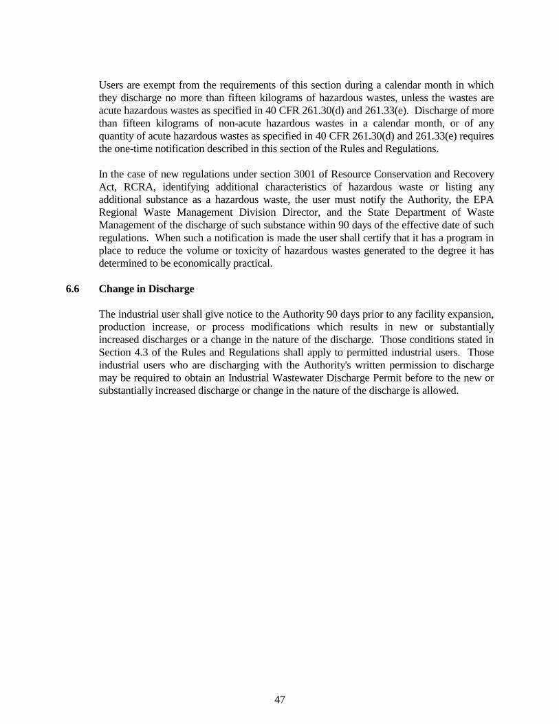
47
Users are exempt from the requirements of this section during a calendar month in which
they discharge no more than fifteen kilograms of hazardous wastes, unless the wastes are acute hazardous wastes as specified in 40 CFR 261.30(d) and 261.33(e). Discharge of more than fifteen kilograms of non-acute hazardous wastes in a calendar month, or of any quantity of acute hazardous wastes as specified in 40 CFR 261.30(d) and 261.33(e) requires the one-time notification described in this section of the Rules and Regulations.
In the case of new regulations under section 3001 of Resource Conservation and Recovery
Act, RCRA, identifying additional characteristics of hazardous waste or listing any additional substance as a hazardous waste, the user must notify the Authority, the EPA Regional Waste Management Division Director, and the State Department of Waste Management of the discharge of such substance within 90 days of the effective date of such regulations. When such a notification is made the user shall certify that it has a program in place to reduce the volume or toxicity of hazardous wastes generated to the degree it has determined to be economically practical.
6.6 Change in Discharge The industrial user shall give notice to the Authority 90 days prior to any facility expansion,
production increase, or process modifications which results in new or substantially increased discharges or a change in the nature of the discharge. Those conditions stated in Section 4.3 of the Rules and Regulations shall apply to permitted industrial users. Those industrial users who are discharging with the Authority's written permission to discharge may be required to obtain an Industrial Wastewater Discharge Permit before to the new or substantially increased discharge or change in the nature of the discharge is allowed.
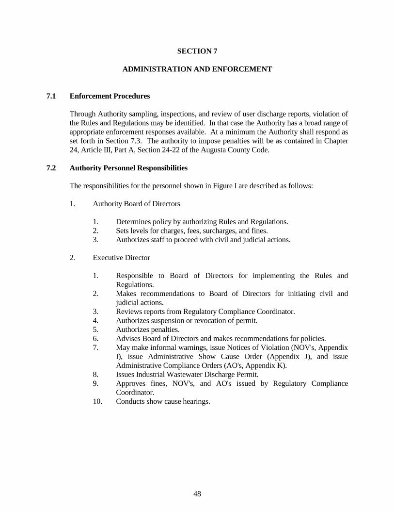
48
SECTION 7 ADMINISTRATION AND ENFORCEMENT 7.1 Enforcement Procedures Through Authority sampling, inspections, and review of user discharge reports, violation of
the Rules and Regulations may be identified. In that case the Authority has a broad range of appropriate enforcement responses available. At a minimum the Authority shall respond as set forth in Section 7.3. The authority to impose penalties will be as contained in Chapter 24, Article III, Part A, Section 24-22 of the Augusta County Code.
7.2 Authority Personnel Responsibilities The responsibilities for the personnel shown in Figure I are described as follows: 1. Authority Board of Directors 1. Determines policy by authorizing Rules and Regulations. 2. Sets levels for charges, fees, surcharges, and fines. 3. Authorizes staff to proceed with civil and judicial actions. 2. Executive Director 1. Responsible to Board of Directors for implementing the Rules and
Regulations. 2. Makes recommendations to Board of Directors for initiating civil and
judicial actions. 3. Reviews reports from Regulatory Compliance Coordinator. 4. Authorizes suspension or revocation of permit. 5. Authorizes penalties. 6. Advises Board of Directors and makes recommendations for policies. 7. May make informal warnings, issue Notices of Violation (NOV's, Appendix
I), issue Administrative Show Cause Order (Appendix J), and issue Administrative Compliance Orders (AO's, Appendix K).
8. Issues Industrial Wastewater Discharge Permit. 9. Approves fines, NOV's, and AO's issued by Regulatory Compliance
Coordinator. 10. Conducts show cause hearings.
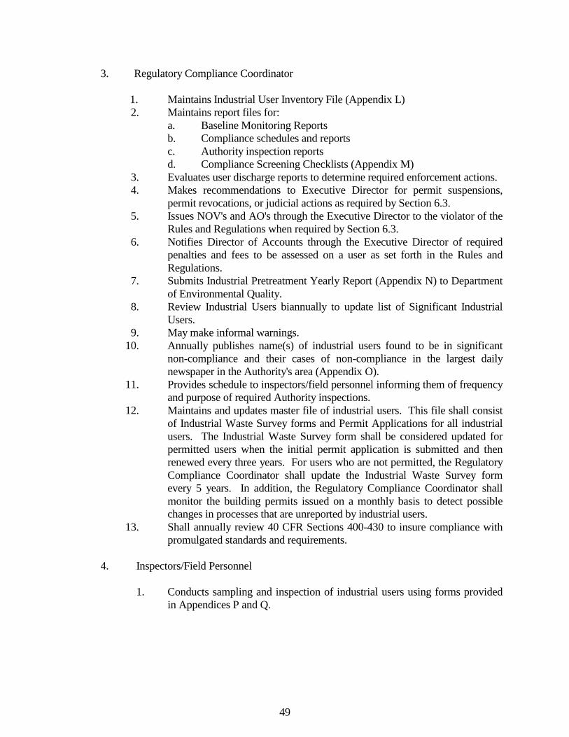
49
3. Regulatory Compliance Coordinator 1. Maintains Industrial User Inventory File (Appendix L) 2. Maintains report files for: a. Baseline Monitoring Reports b. Compliance schedules and reports c. Authority inspection reports d. Compliance Screening Checklists (Appendix M) 3. Evaluates user discharge reports to determine required enforcement actions. 4. Makes recommendations to Executive Director for permit suspensions,
permit revocations, or judicial actions as required by Section 6.3. 5. Issues NOV's and AO's through the Executive Director to the violator of the
Rules and Regulations when required by Section 6.3. 6. Notifies Director of Accounts through the Executive Director of required
penalties and fees to be assessed on a user as set forth in the Rules and Regulations.
7. Submits Industrial Pretreatment Yearly Report (Appendix N) to Department of Environmental Quality.
8. Review Industrial Users biannually to update list of Significant Industrial Users.
9. May make informal warnings. 10. Annually publishes name(s) of industrial users found to be in significant
non-compliance and their cases of non-compliance in the largest daily newspaper in the Authority's area (Appendix O).
11. Provides schedule to inspectors/field personnel informing them of frequency and purpose of required Authority inspections.
12. Maintains and updates master file of industrial users. This file shall consist of Industrial Waste Survey forms and Permit Applications for all industrial users. The Industrial Waste Survey form shall be considered updated for permitted users when the initial permit application is submitted and then renewed every three years. For users who are not permitted, the Regulatory Compliance Coordinator shall update the Industrial Waste Survey form every 5 years. In addition, the Regulatory Compliance Coordinator shall monitor the building permits issued on a monthly basis to detect possible changes in processes that are unreported by industrial users.
13. Shall annually review 40 CFR Sections 400-430 to insure compliance with promulgated standards and requirements.
4. Inspectors/Field Personnel 1. Conducts sampling and inspection of industrial users using forms provided
in Appendices P and Q.

50
2. Reviews user discharge monitoring reports to detect for non-compliance. Completes Compliance Screening checklist based on review and submits to Regulatory Compliance Coordinator.
3. Reports conditions of non-compliance and recommends action to Regulatory Compliance Coordinator.
4. Makes informal warnings for non-compliance when required by Section 6.3. 5. Authority Attorney 1. Advises Authority on legal issues concerning the Rules and Regulations. 2. Advises Authority on enforcement matters. 3. Coordinates judicial enforcement responses. 4. Conducts civil litigation on behalf of Authority. 6. Director of Accounts Assesses user for charges, fees, surcharges, and fines as authorized by the Executive
Director.
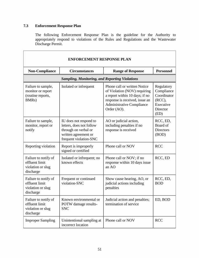
51
7.3 Enforcement Response Plan The following Enforcement Response Plan is the guideline for the Authority to
appropriately respond to violations of the Rules and Regulations and the Wastewater Discharge Permit.
ENFORCEMENT RESPONSE PLAN
Non-Compliance Circumstances Range of Response Personnel
Sampling, Monitoring, and Reporting Violations
Failure to sample, monitor or report (routine reports, BMRs)
Isolated or infrequent Phone call or written Notice of Violation (NOV) requiring a report within 10 days; if no response is received, issue an Administrative Compliance Order (AO).
Regulatory Compliance Coordinator (RCC), Executive Director (ED)
Failure to sample, monitor, report or notify
IU does not respond to letters, does not follow through on verbal or written agreement or frequent violation-SNC
AO or judicial action, including penalties if no response is received
RCC, ED, Board of Directors (BOD)
Reporting violation Report is improperly signed or certified
Phone call or NOV RCC
Failure to notify of effluent limit violation or slug discharge
Isolated or infrequent; no known effects
Phone call or NOV; if no response within 10 days issue an AO
RCC, ED
Failure to notify of effluent limit violation or slug discharge
Frequent or continued violation-SNC
Show cause hearing, AO, or judicial actions including penalties
RCC, ED, BOD
Failure to notify of effluent limit violation or slug discharge
Known environmental or POTW damage results-SNC
Judicial action and penalties; termination of service
ED, BOD
Improper Sampling Unintentional sampling at incorrect location
Phone call or NOV RCC
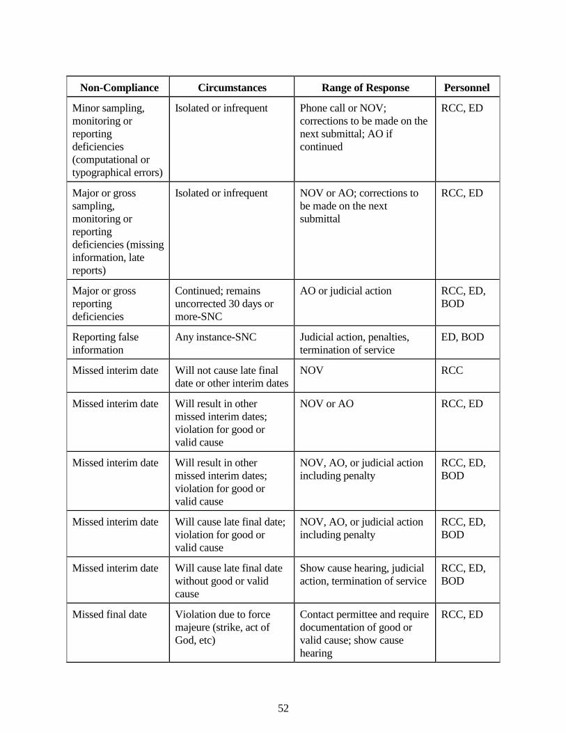
52
Non-Compliance Circumstances Range of Response Personnel
Minor sampling, monitoring or reporting deficiencies (computational or typographical errors)
Isolated or infrequent Phone call or NOV; corrections to be made on the next submittal; AO if continued
RCC, ED
Major or gross sampling, monitoring or reporting deficiencies (missing information, late reports)
Isolated or infrequent NOV or AO; corrections to be made on the next submittal
RCC, ED
Major or gross reporting deficiencies
Continued; remains uncorrected 30 days or more-SNC
AO or judicial action RCC, ED, BOD
Reporting false information
Any instance-SNC Judicial action, penalties, termination of service
ED, BOD
Missed interim date Will not cause late final date or other interim dates
NOV RCC
Missed interim date Will result in other missed interim dates; violation for good or valid cause
NOV or AO RCC, ED
Missed interim date Will result in other missed interim dates; violation for good or valid cause
NOV, AO, or judicial action including penalty
RCC, ED, BOD
Missed interim date Will cause late final date; violation for good or valid cause
NOV, AO, or judicial action including penalty
RCC, ED, BOD
Missed interim date Will cause late final date without good or valid cause
Show cause hearing, judicial action, termination of service
RCC, ED, BOD
Missed final date Violation due to force majeure (strike, act of God, etc)
Contact permittee and require documentation of good or valid cause; show cause hearing
RCC, ED
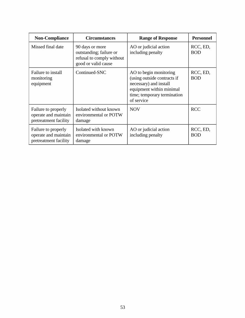
53
Non-Compliance Circumstances Range of Response Personnel
Missed final date 90 days or more outstanding; failure or refusal to comply without good or valid cause
AO or judicial action including penalty
RCC, ED, BOD
Failure to install monitoring equipment
Continued-SNC AO to begin monitoring (using outside contracts if necessary) and install equipment within minimal time; temporary termination of service
RCC, ED, BOD
Failure to properly operate and maintain pretreatment facility
Isolated without known environmental or POTW damage
NOV RCC
Failure to properly operate and maintain pretreatment facility
Isolated with known environmental or POTW damage
AO or judicial action including penalty
RCC, ED, BOD
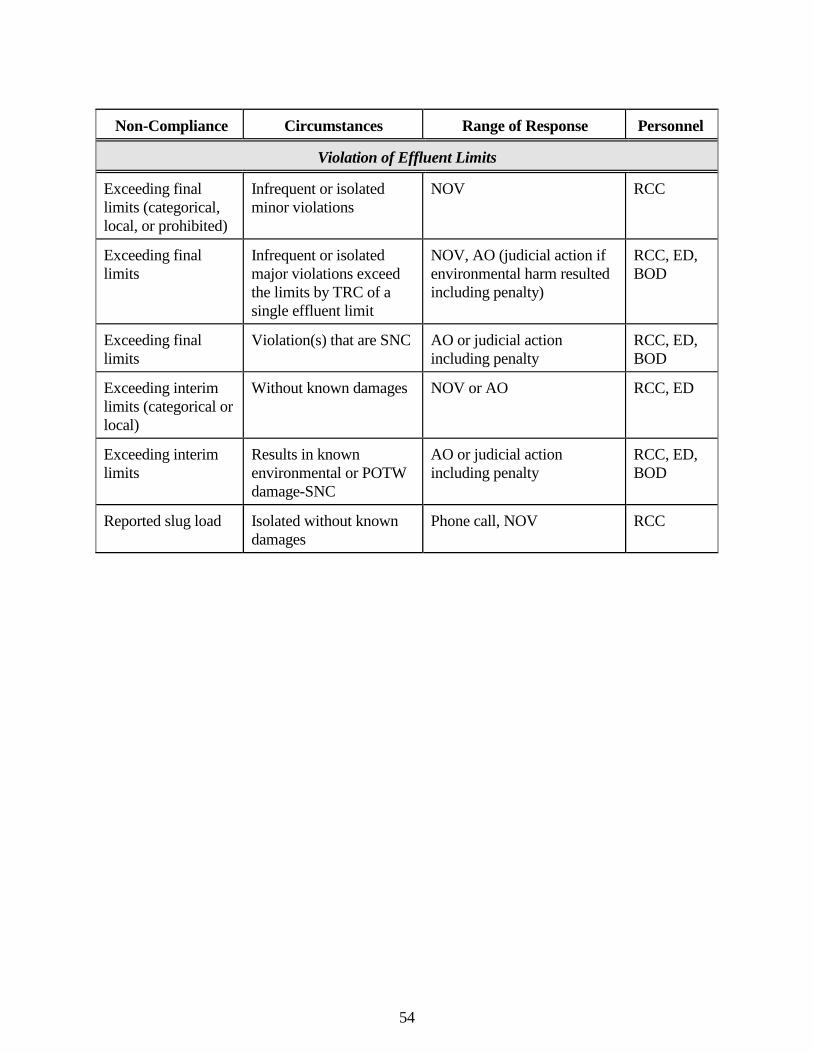
54
Non-Compliance Circumstances Range of Response Personnel
Violation of Effluent Limits
Exceeding final limits (categorical, local, or prohibited)
Infrequent or isolated minor violations
NOV RCC
Exceeding final limits
Infrequent or isolated major violations exceed the limits by TRC of a single effluent limit
NOV, AO (judicial action if environmental harm resulted including penalty)
RCC, ED, BOD
Exceeding final limits
Violation(s) that are SNC AO or judicial action including penalty
RCC, ED, BOD
Exceeding interim limits (categorical or local)
Without known damages NOV or AO RCC, ED
Exceeding interim limits
Results in known environmental or POTW damage-SNC
AO or judicial action including penalty
RCC, ED, BOD
Reported slug load Isolated without known damages
Phone call, NOV RCC
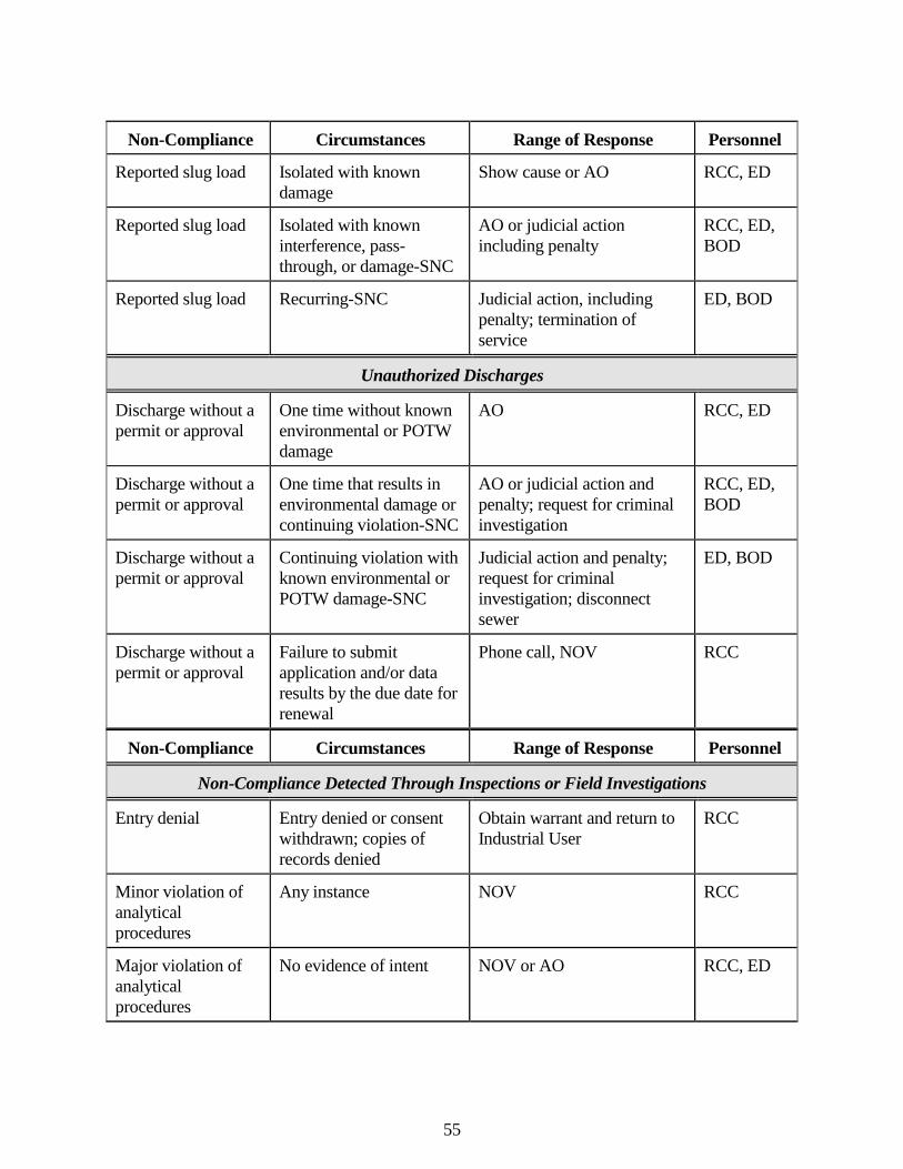
55
Non-Compliance Circumstances Range of Response Personnel
Reported slug load Isolated with known damage
Show cause or AO RCC, ED
Reported slug load Isolated with known interference, pass-through, or damage-SNC
AO or judicial action including penalty
RCC, ED, BOD
Reported slug load Recurring-SNC Judicial action, including penalty; termination of service
ED, BOD
Unauthorized Discharges
Discharge without a permit or approval
One time without known environmental or POTW damage
AO RCC, ED
Discharge without a permit or approval
One time that results in environmental damage or continuing violation-SNC
AO or judicial action and penalty; request for criminal investigation
RCC, ED, BOD
Discharge without a permit or approval
Continuing violation with known environmental or POTW damage-SNC
Judicial action and penalty; request for criminal investigation; disconnect sewer
ED, BOD
Discharge without a permit or approval
Failure to submit application and/or data results by the due date for renewal
Phone call, NOV RCC
Non-Compliance Circumstances Range of Response Personnel
Non-Compliance Detected Through Inspections or Field Investigations
Entry denial Entry denied or consent withdrawn; copies of records denied
Obtain warrant and return to Industrial User
RCC
Minor violation of analytical procedures
Any instance NOV RCC
Major violation of analytical procedures
No evidence of intent NOV or AO RCC, ED
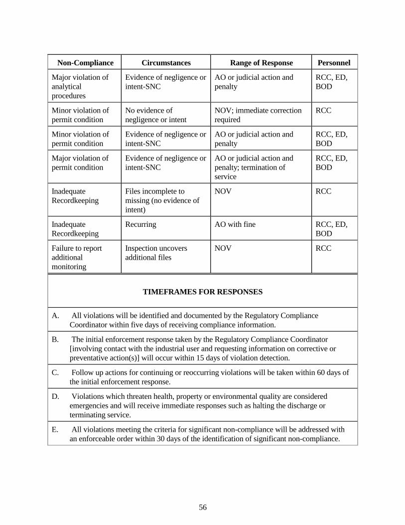
56
Non-Compliance Circumstances Range of Response Personnel
Major violation of analytical procedures
Evidence of negligence or intent-SNC
AO or judicial action and penalty
RCC, ED, BOD
Minor violation of permit condition
No evidence of negligence or intent
NOV; immediate correction required
RCC
Minor violation of permit condition
Evidence of negligence or intent-SNC
AO or judicial action and penalty
RCC, ED, BOD
Major violation of permit condition
Evidence of negligence or intent-SNC
AO or judicial action and penalty; termination of service
RCC, ED, BOD
Inadequate Recordkeeping
Files incomplete to missing (no evidence of intent)
NOV RCC
Inadequate Recordkeeping
Recurring AO with fine RCC, ED, BOD
Failure to report additional monitoring
Inspection uncovers additional files
NOV RCC
TIMEFRAMES FOR RESPONSES
A. All violations will be identified and documented by the Regulatory Compliance Coordinator within five days of receiving compliance information.
B. The initial enforcement response taken by the Regulatory Compliance Coordinator [involving contact with the industrial user and requesting information on corrective or preventative action(s)] will occur within 15 days of violation detection.
C. Follow up actions for continuing or reoccurring violations will be taken within 60 days of the initial enforcement response.
D. Violations which threaten health, property or environmental quality are considered emergencies and will receive immediate responses such as halting the discharge or terminating service.
E. All violations meeting the criteria for significant non-compliance will be addressed with an enforceable order within 30 days of the identification of significant non-compliance.
57
7.4 Enforcement Action Descriptions 1. Notification of Violation a. Purpose Whenever the Authority finds that any user has violated or is violating these
Rules and Regulations, wastewater discharge permit, or any prohibition, limitation, or requirements contained herein, the Authority may serve upon said user a written notice.
b. Procedure The Notice of Violation shall be served to the user by certified mail or in
person. The text of the Notice of Violation shall state the nature of the violation, date, and evidence.
c. Consequences Within 10 days from the receipt date of the notice, an explanation of the
violation and a plan for the satisfactory correction and prevention thereof, to include specific required actions, shall be submitted to the Authority. Submission of the plan in no way relieves the user of liability for any violations occurring before or after receipt of the Notice of Violation.
2. Show Cause Hearing a. Purpose The Authority may order any user who causes or allows an unauthorized
discharge to enter a wastewater treatment system to show cause before Authority officials why a proposed enforcement action should not be taken.
b. Procedure A notice shall be served on the user which specifies (1) the time and place of
a hearing to be held by the Authority regarding the violation; (2) the reasons why a proposed enforcement action is to be taken; and (3) the proposed enforcement action. The notice shall also direct the user to show cause before the Authority why the proposed enforcement action should not be taken. The notice of the hearing shall be served personally or by registered or certified mail (return receipt requested) at least ten days before the hearing. Service may be made on any agent or officer of a corporation.
The Authority may itself conduct the hearing and take the evidence, or may
designate any of its agents to: (1) Issue in the names of the Authority notices of hearings requesting the
attendance and testimony of witnesses and the production of evidence relevant to any matter involved in such hearings.
58
(2) Take the evidence; and (3) Transmit a report of the evidence and hearing, including transcripts
and other evidence, together with recommendations to the Authority for action thereon.
At any hearing held pursuant to these Rules and Regulations, testimony
taken must be under oath and recorded and typed verbatim. The transcript, so recorded, may be made available to any member of the public, or any party to the hearing upon payment of the usual charges thereof.
c. Consequences After the Authority has reviewed the evidence, it may issue an order to the
user responsible for the discharge directing that, following a specified time period, the public sewer service will be discontinued unless adequate treatment facilities, devices or other related appurtenances shall have been installed on existing treatment facilities, and those devices or other related appurtenances are properly operated. Further orders and directives as necessary and appropriate may be issued.
3. Administrative Compliance Order a. Purpose When the Authority finds that a user has violated or continues to violate the
ordinance or a permit or order issued thereunder, an Administrative Compliance Order may be issued to the user responsible for the discharge directing that following a specified time period, sewer services shall be discontinued unless adequate treatment facilities, devices, or other related appurtenances have been installed and are properly operated to eliminate the cause of the violation. Orders may also contain such other requirements as might be reasonably necessary and appropriate to address the non-compliance, including the installation of pretreatment technology, additional self-monitoring, and management practices. Any deadlines established in the Administrative Compliance Order shall not extend any compliance date beyond any applicable Federal deadlines.
b. Procedure The Administrative Order shall be served to the user by certified mail or in
person. The user shall comply with the Order or be subjected to the penalties described therein.
59
c. Consequences The user shall submit a written report to the Authority within 5 days of each
compliance date contained in the Administrative Order. The report shall state whether the user has taken the action required by the date specified.
4. Permit Suspension a. Purpose The Authority may suspend the wastewater treatment service and/or an
Industrial Wastewater Discharge Permit when such suspension is necessary, in the opinion of the Authority, in order to stop an actual or threatened discharge which presents or may present an imminent or substantial endangerment to the health or welfare of persons or the environment; causes interference to the wastewater treatment system; or causes the Authority to violate any condition of the applicable VPDES permit.
b. Procedure The Authority shall submit a Notice of Suspension to the user in person or
by certified mail. The Notice of Suspension shall include the reason for suspension, the effective date of suspension, and the conditions under which the permit shall be restored.
c. Consequences Any user notified of a suspension of the wastewater treatment service and/or
of the Industrial Wastewater Discharge Permit shall immediately stop or eliminate the contribution. In the event of a failure of the said user to comply voluntarily with the suspension order, the Authority shall take such steps as deemed necessary including immediate severance of the public sewer connection, to prevent or minimize damage to the sanitary sewer or wastewater treatment facility or endangerment to any individuals. The Industrial Wastewater Discharge Permit and/or the wastewater treatment service shall be reinstated upon proof of the elimination of the non-complying discharge. A detailed written statement submitted by the user describing the causes of the harmful contribution and the measures taken to prevent any future occurrence shall be submitted to the Authority within 15 days of the date of occurrence. Upon acceptance by the Authority, the suspension will be lifted and the user will be notified of the permit restoration.
60
5. Permit Revocation a. Purpose The Authority has the right to revoke a discharge permit as a positive
measure. Any user who violates the following conditions of the Rules and Regulations or applicable state and federal regulations, is subject to having its permit revoked:
(1) Failure of a user to factually report the wastewater constituents and
characteristics of its discharges. (2) Failure of the user to report significant changes in operations, or
wastewater constituents and characteristics. (3) Refusal of reasonable access to the user's premises for the purpose of
inspection or monitoring. (4) Obtaining a permit by misrepresentation or failure to fully disclose
all relevant facts. (5) A change in any condition that requires a temporary or permanent
increase, reduction, or elimination of the permitted discharge. (6) Violation of conditions of the permit. b. Procedure The Authority shall submit a Notice of Revocation to the user in person or
by certified mail. The Notice of Revocation shall include the effective date of and the reason for revocation.
c. Consequences of Revocation Before any further discharge of industrial wastewater may be made by a
discharger whose Permit has been revoked, the discharger must apply for, and be granted, a reinstatement of the terminated permit, or a new permit, as the Authority may require, and pay all delinquent fees, charges and costs occasioned by the violation.
6. Termination of Service Water and/or sewer service to the User may be terminated when: a. Materials damaging to sewer lines or treatment process are released by the
User to the sewer, causing deterioration of these structures or interfering with proper conveyance and treatment of wastewater;
61
b. The effluent from the wastewater treatment plant is no longer of a quality
permitted for discharge to a watercourse, and it is found that the User is delivering wastes to the wastewater system that cannot be sufficiently treated or require pretreatment; or
c. The User 1) discharges wastewater that is in significant non-compliance of the
permit issued; or 2) fails to pay user charges for public sewer services when due; or 3) discharges prohibited wastes to public sewers; or 4) violates any requirement of the Rules and Regulations
The Executive Director will endeavor within reasonable limits to eliminate or remedy violation without resorting to termination of service. However, if those efforts have been unsuccessful, the Executive Director is authorized to terminate service to a User.
The Executive Director shall not terminate service to a User without first delivering to the User written notice of such proposed termination. The notice shall state the reason or reasons of said termination and may allow a reasonable time for satisfactory compliance to meet the wastewater constituents and/or characteristic limitation(s) that are being violated.
Nothing in the permit is intended to deter, hinder or stop the Service Authority personnel from taking immediate action to terminate service to a User when there is imminent risk of great danger to the wastewater facilities and or personnel.
7. Criminal and Civil Liability a. Any person who violates any rule or regulation of the Authority relating to
requirements for direct and indirect discharges into the wastewater collection and treatment systems of the Augusta County Service Authority shall be deemed to have violated Article III, Chapter 24 of the Augusta County Ordinance, and, upon conviction thereof, may be subject to the penalties set forth in subsection B of this section as well as to the responsibilities and liabilities set forth in subsection C below.
62
b. Any person who willfully or negligently violates any provision of Article III,
Chapter 24 of the Augusta County Ordinance may be subject to criminal penalties of a fine of up to $1,000 per day of violation, or by imprisonment for up to twelve months, or by both fine and imprisonment.
c. Further, any person who violates any provision of Article III, Chapter 24 of
the Augusta County Ordinance or any condition or limitation of a Permit, or plan approval related thereto, shall be financially responsible and liable to the Authority, in addition to normal service charges and surcharges, for all costs incurred by the Authority associated with the violation of Article III, Chapter 24 of Augusta County Ordinance, including, but not limited to the following:
(1) Cost of mileage and labor incurred in detecting and correcting the
violation. (2) Laboratory analysis costs associated with detecting and correcting
the violation. (3) Additional treatment costs caused by the violation or associated with
detecting and correcting the violation. (4) Costs of any additional equipment acquired or expended by the
Authority for detecting or correcting the violation. (5) Repair or replacement of any part of the sewage system damaged by
the violation. (6) Any liability, damages, fines or penalties incurred by the Authority
as a result of the violation. (7) Other costs as are associated with the detecting and correcting the
violation.
In addition, any user who violates any provision of the Rules and Regulations or any order of permit issued under the Rules and Regulations shall be liable for a civil penalty of up to $1,000 per day per violation.
63
8. Legal Action
If any user discharges wastewater, industrial wastes or other wastes into a wastewater treatment system contrary to the provisions of the Rules and Regulations, Federal or State Pretreatment Requirements, or any order of the Authority, an attorney designated by the Authority may commence an action for appropriate legal and/or equitable relief in the Circuit Court of Augusta County. Injunctive relief may be sought for any violation of the Rules and Regulation.
9. Cost Recovery
In addition to the penalties provided in the Rules and Regulations, the Authority may recover reasonable attorneys' fees, court costs, court reporters' fees and other expenses of litigation by appropriate suit at law against the user found to have violated the Rules and Regulations or the orders, rules, regulations and permits issued hereunder.
7.5. Inspections and Testing by Authority Personnel 1. Frequency Inspectors/Field Personnel shall, at a minimum, make facility inspections
and perform wastewater testing of permitted significant industrial users at the following indicated frequencies.
User Discharge Rate Facility Wastewater GPD Inspections Testing 0 - 100,000 1/year 2/year > 100,000 1/year 4/year For those industrial users who do not have an Industrial Wastewater
Discharge Permit but who are discharging with the Authority's written permission to discharge, only wastewater testing shall be conducted unless a possible discharge violation is detected in which case a facility inspection may be conducted. Wastewater testing for this category of industrial user shall typically be conducted on an annual basis unless special or unusual circumstances indicate a different frequency is more appropriate.
2. Facility Inspections Facility inspections shall be conducted by Inspectors using the checklist of
Appendix P. The purpose of the facility inspections is to verify overall compliance with the provisions of the Rules and Regulations.
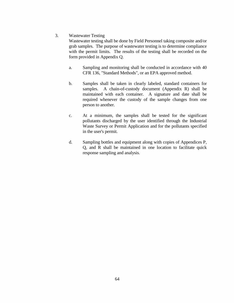
64
3. Wastewater Testing Wastewater testing shall be done by Field Personnel taking composite and/or
grab samples. The purpose of wastewater testing is to determine compliance with the permit limits. The results of the testing shall be recorded on the form provided in Appendix Q.
a. Sampling and monitoring shall be conducted in accordance with 40
CFR 136, "Standard Methods", or an EPA approved method. b. Samples shall be taken in clearly labeled, standard containers for
samples. A chain-of-custody document (Appendix R) shall be maintained with each container. A signature and date shall be required whenever the custody of the sample changes from one person to another.
c. At a minimum, the samples shall be tested for the significant
pollutants discharged by the user identified through the Industrial Waste Survey or Permit Application and for the pollutants specified in the user's permit.
d. Sampling bottles and equipment along with copies of Appendices P,
Q, and R shall be maintained in one location to facilitate quick response sampling and analysis.
65
SECTION 8 ORGANIZATION OF AUGUSTA COUNTY SERVICE AUTHORITY 8.1. Personnel The Authority Staff is well qualified to implement the pretreatment program. The Staff is
composed of two positions requiring Professional Engineering licenses and nine positions requiring certified operators licenses ranging from Class I to Class III. All employees are encouraged to enroll in continuing education curriculum, seminars or short courses, as well as an active on the job training program. Figure I illustrates the organization of the Authority for implementing the Rules and Regulations.
8.2. Laboratory Services The Service Authority maintains a modern EPA Approved Laboratory for VPDES testing.
Contract and/or special services are available at private laboratories nearby. 8.3. Sampling Equipment The Service Authority maintains automatic samplers at its larger wastewater facilities. In
addition the Service Authority has three (3) portable samplers; ten (10) pH samplers; and ten (10) D O meters.
The Service Authority owns and operates its own T.V. Cameras for special surveillance, as
well as I & I studies. Seven vehicles are assigned to the sewage operations with additional vehicles and/or special use vehicles available from the Service Authority motor pool.

Appendix A
Application for Discharge Permit
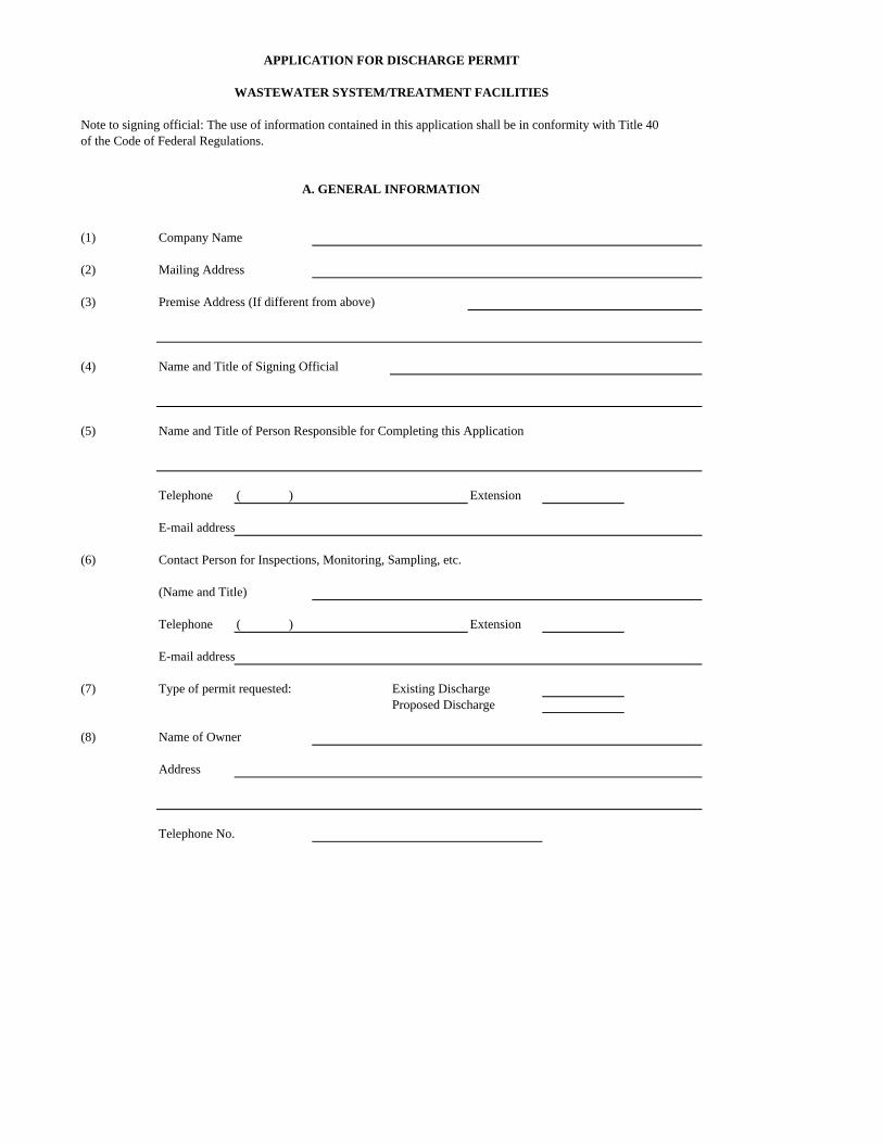
Note to signing official: The use of information contained in this application shall be in conformity with Title 40of the Code of Federal Regulations.
(1) Company Name
(2) Mailing Address
(3) Premise Address (If different from above)
(4) Name and Title of Signing Official
(5) Name and Title of Person Responsible for Completing this Application
Telephone ( ) Extension
E-mail address
(6) Contact Person for Inspections, Monitoring, Sampling, etc.
(Name and Title)
Telephone ( ) Extension
E-mail address
(7) Type of permit requested: Existing DischargeProposed Discharge
(8) Name of Owner
Address
Telephone No.
APPLICATION FOR DISCHARGE PERMIT
WASTEWATER SYSTEM/TREATMENT FACILITIES
A. GENERAL INFORMATION
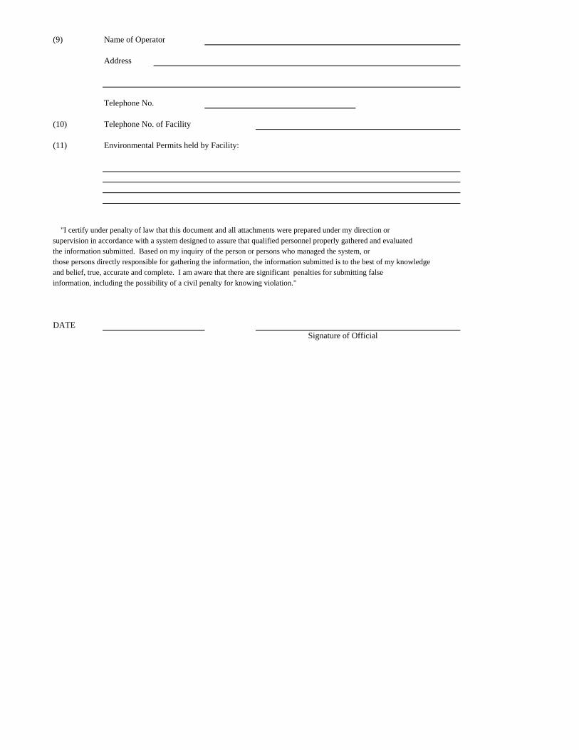
(9) Name of Operator
Address
Telephone No.
(10) Telephone No. of Facility
(11) Environmental Permits held by Facility:
"I certify under penalty of law that this document and all attachments were prepared under my direction orsupervision in accordance with a system designed to assure that qualified personnel properly gathered and evaluatedthe information submitted. Based on my inquiry of the person or persons who managed the system, orthose persons directly responsible for gathering the information, the information submitted is to the best of my knowledgeand belief, true, accurate and complete. I am aware that there are significant penalties for submitting falseinformation, including the possibility of a civil penalty for knowing violation."
DATESignature of Official
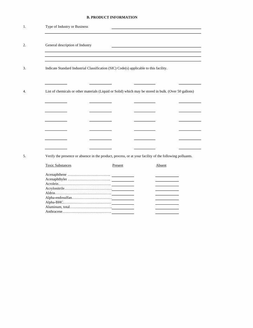
1. Type of Industry or Business
2. General description of Industry
3. Indicate Standard Industrial Classification (SIC) Code(s) applicable to this facility.
4. List of chemicals or other materials (Liquid or Solid) which may be stored in bulk. (Over 50 gallons)
5. Verify the presence or absence in the product, process, or at your facility of the following polluants.
Toxic Substances Present Absent
Acenaphthene ……………………………..Acenaphthylen……………………………..Acrolein…………………………………….Acrylonitrile…………………………………Aldrin……………………………………….Alpha-endosulfan……………………………Alpha-BHC…………………………………Aluminum, total……………………………..Anthracene………………………………….
B. PRODUCT INFORMATION
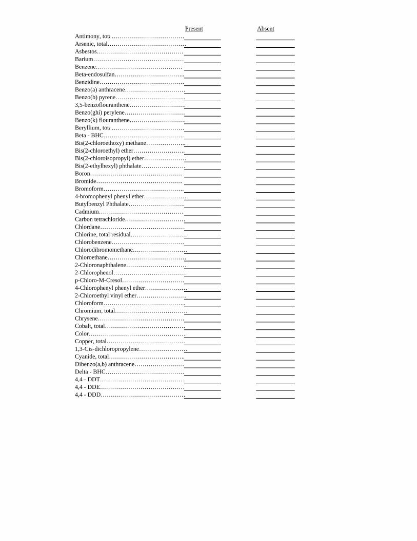
Present AbsentAntimony, tota………………………………Arsenic, total…………………………………Asbestos…………………………………….Barium………………………………………Benzene…………………………………….Beta-endosulfan……………………………..Benzidine……………………………………Benzo(a) anthracene…………………………Benzo(b) pyrene……………………………..3,5-benzoflouranthene……………………….Benzo(ghi) perylene…………………………Benzo(k) flouranthene……………………….Beryllium, tota………………………………Beta - BHC………………………………….Bis(2-chloroethoxy) methane………………..Bis(2-chloroethyl) ether……………………..Bis(2-chloroisopropyl) ether…………………Bis(2-ethylhexyl) phthalate………………….Boron……………………………………….Bromide…………………………………….Bromoform………………………………….4-bromophenyl phenyl ether…………………Butylbenzyl Phthalate……………………….Cadmium……………………………………Carbon tetrachloride…………………………Chlordane……………………………………Chlorine, total residual……………………….Chlorobenzene………………………………Chlorodibromomethane………………………Chloroethane…………………………………2-Chloronaphthalene…………………………2-Chlorophenol………………………………p-Chloro-M-Cresol………………………….4-Chlorophenyl phenyl ether…………………2-Chloroethyl vinyl ether…………………….Chloroform…………………………………..Chromium, total………………………………Chrysene…………………………………….Cobalt, total………………………………….Color…………………………………………Copper, total…………………………………1,3-Cis-dichloropropylene……………………Cyanide, total………………………………..Dibenzo(a,b) anthracene…………………….Delta - BHC…………………………………4,4 - DDT……………………………………4,4 - DDE……………………………………4,4 - DDD……………………………………
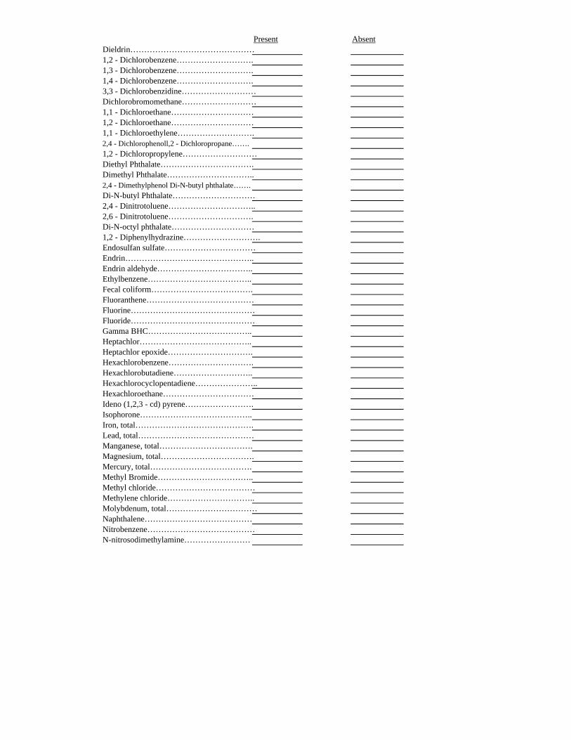
Present AbsentDieldrin………………………………………1,2 - Dichlorobenzene……………………….1,3 - Dichlorobenzene……………………….1,4 - Dichlorobenzene……………………….3,3 - Dichlorobenzidine………………………Dichlorobromomethane………………………1,1 - Dichloroethane…………………………1,2 - Dichloroethane…………………………1,1 - Dichloroethylene……………………….2,4 - Dichlorophenoll,2 - Dichloropropane…….1,2 - Dichloropropylene………………………Diethyl Phthalate…………………………….Dimethyl Phthalate…………………………..2,4 - Dimethylphenol Di-N-butyl phthalate…….Di-N-butyl Phthalate…………………………2,4 - Dinitrotoluene…………………………..2,6 - Dinitrotoluene………………………….Di-N-octyl phthalate…………………………1,2 - Diphenylhydrazine……………………….Endosulfan sulfate……………………………Endrin………………………………………..Endrin aldehyde……………………………..Ethylbenzene………………………………..Fecal coliform……………………………….Fluoranthene…………………………………Fluorine………………………………………Fluoride………………………………………Gamma BHC………………………………..Heptachlor…………………………………..Heptachlor epoxide………………………….Hexachlorobenzene………………………….Hexachlorobutadiene………………………..Hexachlorocyclopentadiene…………………..Hexachloroethane……………………………Ideno (1,2,3 - cd) pyrene…………………….Isophorone…………………………………..Iron, total…………………………………….Lead, total……………………………………Manganese, total…………………………….Magnesium, total…………………………….Mercury, total……………………………….Methyl Bromide……………………………..Methyl chloride………………………………Methylene chloride…………………………..Molybdenum, total……………………………Naphthalene…………………………………Nitrobenzene…………………………………N-nitrosodimethylamine……………………
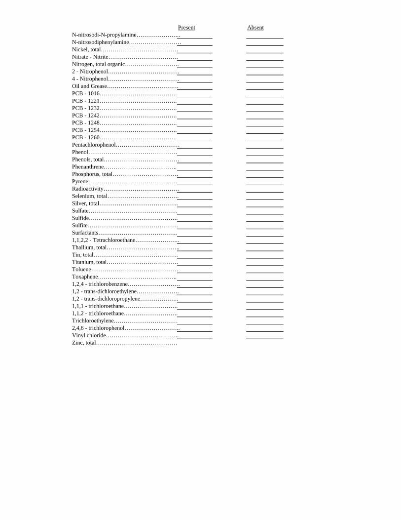
Present AbsentN-nitrosodi-N-propylamine…………………..N-nitrosodiphenylamine………………………Nickel, total………………………………….Nitrate - Nitrite………………………………Nitrogen, total organic……………………….2 - Nitrophenol……………………………….4 - Nitrophenol……………………………….Oil and Grease……………………………….PCB - 1016………………………………….PCB - 1221………………………………….PCB - 1232………………………………….PCB - 1242………………………………….PCB - 1248………………………………….PCB - 1254………………………………….PCB - 1260………………………………….Pentachlorophenol……………………………Phenol……………………………………….Phenols, total…………………………………Phenanthrene………………………………..Phosphorus, total…………………………….Pyrene……………………………………….Radioactivity…………………………………Selenium, total……………………………….Silver, total…………………………………..Sulfate……………………………………….Sulfide……………………………………….Sulfite………………………………………..Surfactants…………………………………..1,1,2,2 - Tetrachloroethane…………………..Thallium, total………………………………..Tin, total……………………………………..Titanium, total……………………………….Toluene………………………………………Toxaphene…………………………………..1,2,4 - trichlorobenzene………………………1,2 - trans-dichloroethylene………………….1,2 - trans-dichloropropylene………………..1,1,1 - trichloroethane……………………….1,1,2 - trichloroethane……………………….Trichloroethylene……………………………2,4,6 - trichlorophenol………………………..Vinyl chloride………………………………..Zinc, total……………………………………
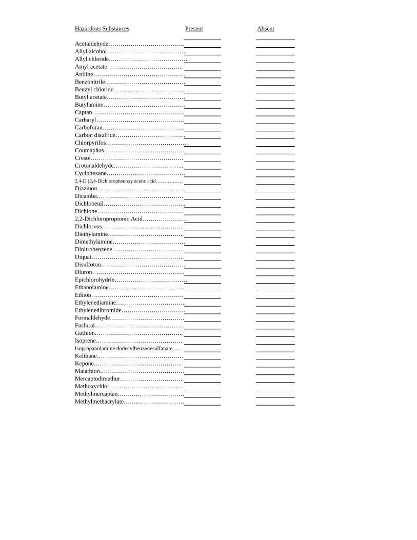
Hazardous Substances Present Absent
Acetaldehyde………………………………..Allyl alcohol………………………………….Allyl chloride…………………………………Amyl acetate………………………………..Aniline……………………………………….Benzonitrile………………………………….Benzyl chloride………………………………Butyl acetate…………………………………Butylamine…………………………………..Captan……………………………………….Carbaryl……………………………………..Carbofuran…………………………………..Carbon disulfide……………………………..Chlorpyrifos………………………………….Coumaphos………………………………….Cresol……………………………………….Crotonaldehyde……………………………..Cyclohexane…………………………………2,4-D (2,4-Dichlorophenoxy acetic acid…………….
Diazinon……………………………………..Dicamba…………………………………….Dichlobenil…………………………………..Dichlone…………………………………….2,2-Dichloropropionic Acid………………….Dichlorvos…………………………………..Diethylamine………………………………..Dimethylamine………………………………Dinitrobenzene………………………………Diquat……………………………………….Disulfoton……………………………………Diuron……………………………………….Epichlorohydrin………………………………Ethanolamine………………………………..Ethion……………………………………….Ethylenediamine……………………………..Ethylenedibromide…………………………..Formaldehyde……………………………….Furfural……………………………………..Guthion……………………………………..Isoprene…………………………………….Isopropanolamine dodecylbenzenesulfanate…..Kelthane…………………………………….Kepone……………………………………..Malathion……………………………………Mercaptodimethur…………………………..Methoxychlor……………………………….Methylmercaptan……………………………Methylmethacrylate…………………………
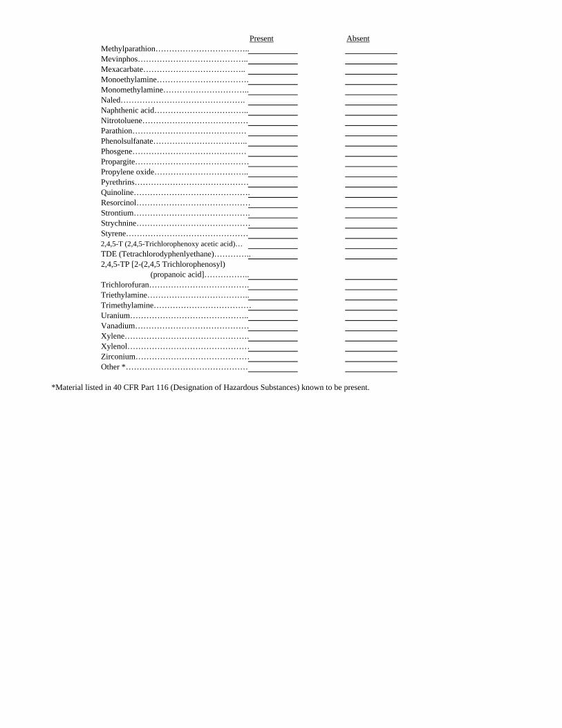
Present AbsentMethylparathion……………………………..Mevinphos…………………………………..Mexacarbate………………………………..Monoethylamine…………………………….Monomethylamine…………………………..Naled……………………………………….Naphthenic acid……………………………..Nitrotoluene…………………………………Parathion……………………………………Phenolsulfanate……………………………..Phosgene……………………………………Propargite……………………………………Propylene oxide……………………………..Pyrethrins……………………………………Quinoline…………………………………….Resorcinol……………………………………Strontium…………………………………….Strychnine……………………………………Styrene………………………………………2,4,5-T (2,4,5-Trichlorophenoxy acetic acid)…TDE (Tetrachlorodyphenlyethane)…………..2,4,5-TP [2-(2,4,5 Trichlorophenosyl)
(propanoic acid]……………..Trichlorofuran……………………………….Triethylamine………………………………..Trimethylamine………………………………Uranium……………………………………..Vanadium……………………………………Xylene……………………………………….Xylenol………………………………………Zirconium……………………………………Other *………………………………………
*Material listed in 40 CFR Part 116 (Designation of Hazardous Substances) known to be present.
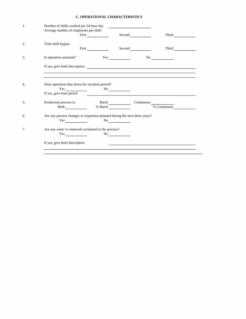
1. Number of shifts worked per 24 hour dayAverage number of employees per shift:
First Second Third
2. Time shift begins:First Second Third
3. Is operation seasonal? Yes No
If yes, give brief description
4. Does operation shut down for vacation period?Yes No
If yes, give time period
5, Production process is: Batch ContinuousBoth % Batch % Continuous
6. Are any process changes or expansion planned during the next three years?Yes No
7. Are any water or materials reclaimed in the process?Yes No
If yes, give brief description
C. OPERATIONAL CHARACTERISTICS
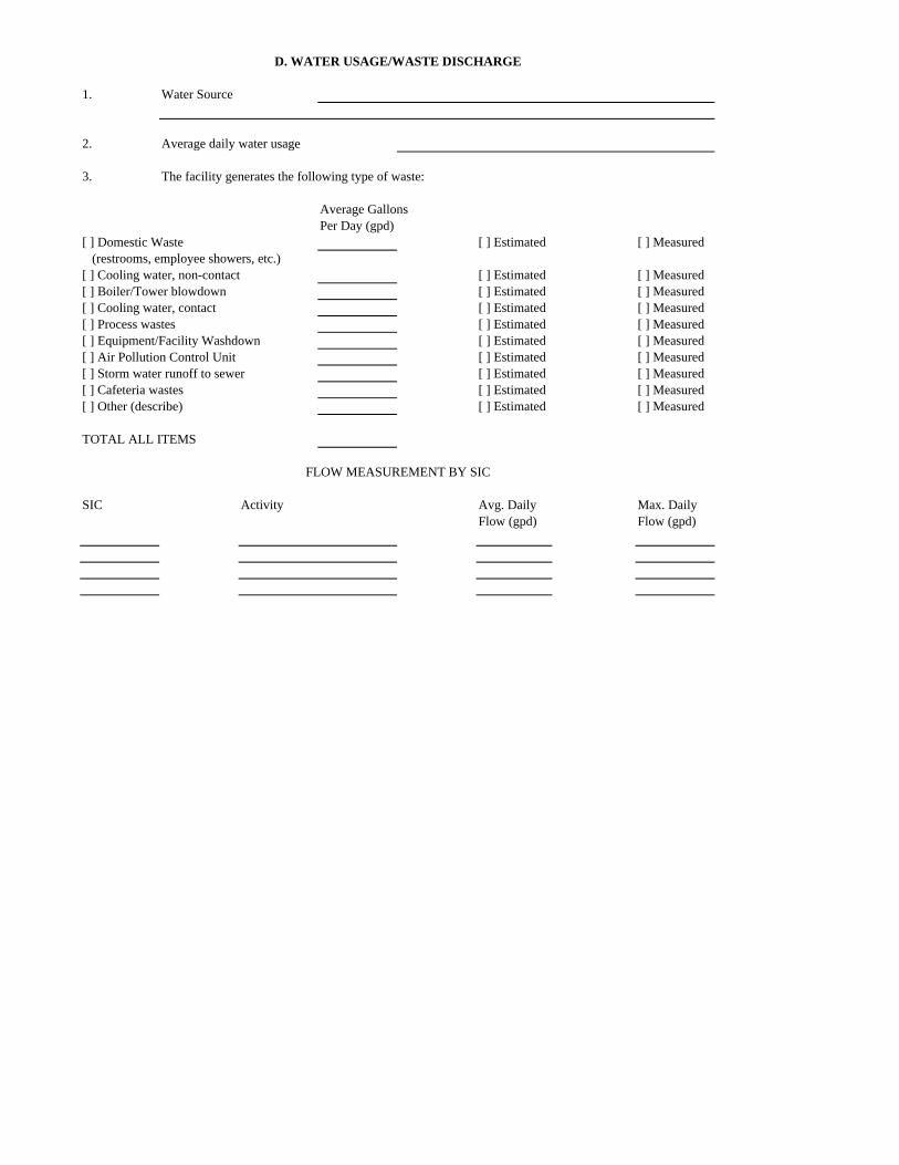
1. Water Source
2. Average daily water usage
3. The facility generates the following type of waste:
Average GallonsPer Day (gpd)
[ ] Domestic Waste [ ] Estimated [ ] Measured (restrooms, employee showers, etc.)[ ] Cooling water, non-contact [ ] Estimated [ ] Measured[ ] Boiler/Tower blowdown [ ] Estimated [ ] Measured[ ] Cooling water, contact [ ] Estimated [ ] Measured[ ] Process wastes [ ] Estimated [ ] Measured[ ] Equipment/Facility Washdown [ ] Estimated [ ] Measured[ ] Air Pollution Control Unit [ ] Estimated [ ] Measured[ ] Storm water runoff to sewer [ ] Estimated [ ] Measured[ ] Cafeteria wastes [ ] Estimated [ ] Measured[ ] Other (describe) [ ] Estimated [ ] Measured
TOTAL ALL ITEMS
SIC Activity Avg. Daily Max. DailyFlow (gpd) Flow (gpd)
D. WATER USAGE/WASTE DISCHARGE
FLOW MEASUREMENT BY SIC
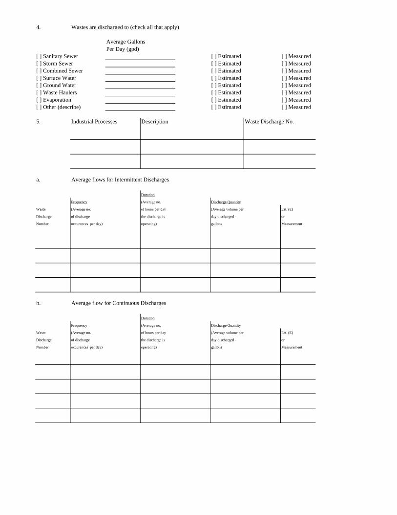
4. Wastes are discharged to (check all that apply)
Average GallonsPer Day (gpd)
[ ] Sanitary Sewer [ ] Estimated [ ] Measured[ ] Storm Sewer [ ] Estimated [ ] Measured[ ] Combined Sewer [ ] Estimated [ ] Measured[ ] Surface Water [ ] Estimated [ ] Measured[ ] Ground Water [ ] Estimated [ ] Measured[ ] Waste Haulers [ ] Estimated [ ] Measured[ ] Evaporation [ ] Estimated [ ] Measured[ ] Other (describe) [ ] Estimated [ ] Measured
5. Industrial Processes Description Waste Discharge No.
a. Average flows for Intermittent Discharges
Duration
Frequency (Average no. Discharge Quantity
Waste (Average no. of hours per day (Average volume per Est. (E)
Discharge of discharge the discharge is day discharged - or
Number occurences per day) operating) gallons Measurement
b. Average flow for Continuous Discharges
Duration
Frequency (Average no. Discharge Quantity
Waste (Average no. of hours per day (Average volume per Est. (E)
Discharge of discharge the discharge is day discharged - or
Number occurences per day) operating) gallons Measurement
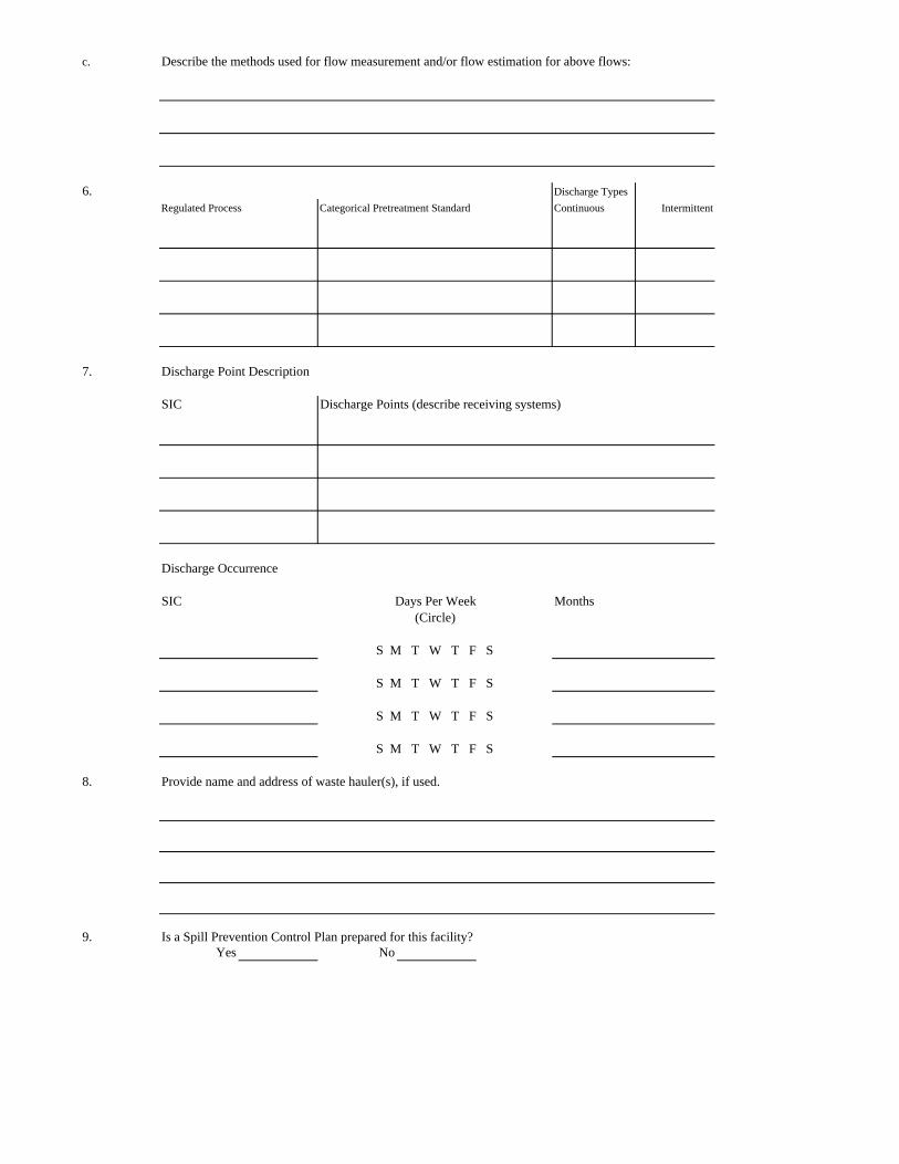
c. Describe the methods used for flow measurement and/or flow estimation for above flows:
6. Discharge Types
Regulated Process Categorical Pretreatment Standard Continuous Intermittent
7. Discharge Point Description
SIC Discharge Points (describe receiving systems)
Discharge Occurrence
SIC Months
8. Provide name and address of waste hauler(s), if used.
9. Is a Spill Prevention Control Plan prepared for this facility?Yes No
S M T W T F S
S M T W T F S
S M T W T F S
S M T W T F S
Days Per Week(Circle)
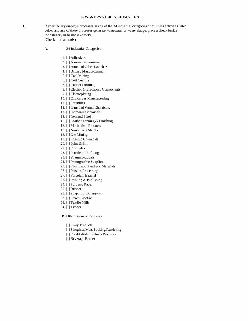
1. If your facility employs processes in any of the 34 industrial categories or business activities listedbelow and any of these processes generate wastewater or waste sludge, place a check besidethe category or business activity.(Check all that apply)
A. 34 Industrial Categories
1. [ ] Adhesives2. [ ] Aluminum Forming3. [ ] Auto and Other Laundries4. [ ] Battery Manufacturing5. [ ] Coal Mining6. [ ] Coil Coating7. [ ] Copper Forming8. [ ] Electric & Electronic Components9. [ ] Electroplating
10. [ ] Explosives Manufacturing11. [ ] Foundries12. [ ] Gum and Wood Chemicals13. [ ] Inorganic Chemicals14. [ ] Iron and Steel15. [ ] Leather Tanning & Finishing16. [ ] Mechanical Products17. [ ] Nonferrous Metals18. [ ] Ore Mining19. [ ] Organic Chemicals20. [ ] Paint & Ink21. [ ] Pesticides22. [ ] Petroleum Refining23. [ ] Pharmaceuticals24. [ ] Photographic Supplies25. [ ] Plastic and Synthetic Materials26. [ ] Plastics Processing27. [ ] Porcelain Enamel28. [ ] Printing & Publishing29. [ ] Pulp and Paper30. [ ] Rubber31. [ ] Soaps and Detergents32. [ ] Steam Electric33. [ ] Textile Mills34. [ ] Timber
B. Other Business Activitiy
[ ] Dairy Products[ ] Slaughter/Meat Packing/Rendering[ ] Food/Edible Products Processor[ ] Beverage Bottler
E. WASTEWATER INFORMATION
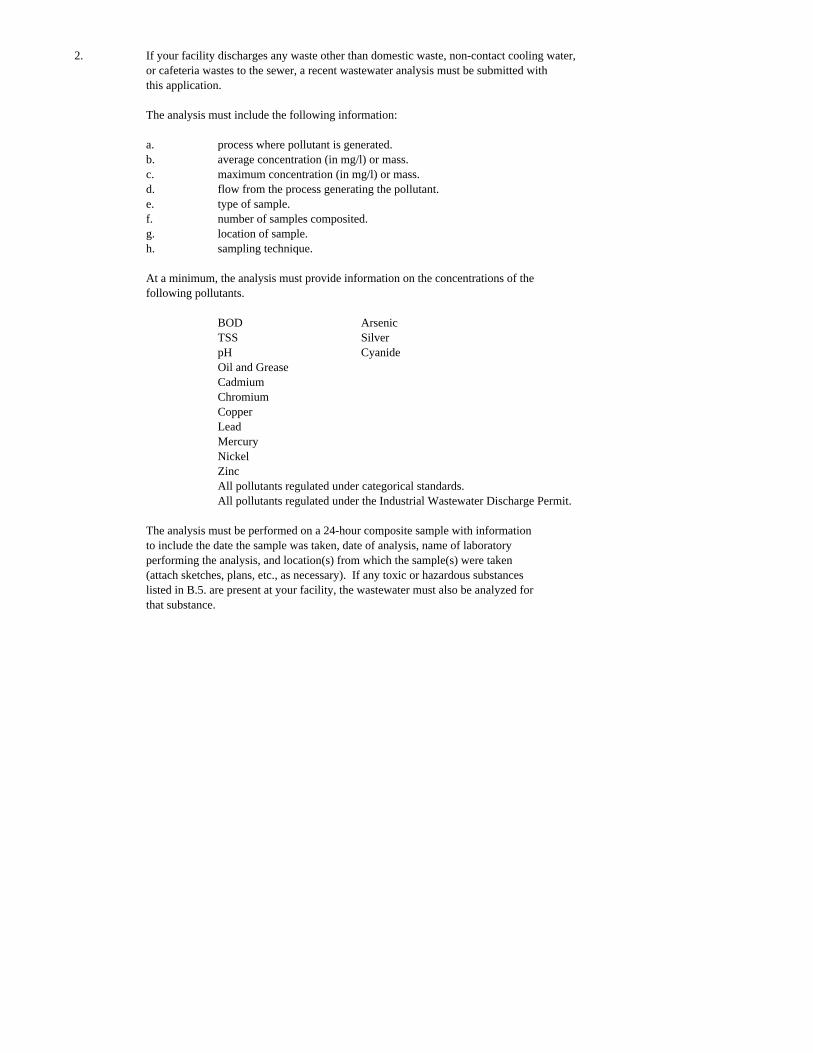
2. If your facility discharges any waste other than domestic waste, non-contact cooling water,or cafeteria wastes to the sewer, a recent wastewater analysis must be submitted withthis application.
The analysis must include the following information:
a. process where pollutant is generated.b. average concentration (in mg/l) or mass.c. maximum concentration (in mg/l) or mass.d. flow from the process generating the pollutant.e. type of sample.f. number of samples composited.g. location of sample.h. sampling technique.
At a minimum, the analysis must provide information on the concentrations of thefollowing pollutants.
BOD ArsenicTSS SilverpH CyanideOil and GreaseCadmiumChromiumCopperLeadMercuryNickelZincAll pollutants regulated under categorical standards.All pollutants regulated under the Industrial Wastewater Discharge Permit.
The analysis must be performed on a 24-hour composite sample with informationto include the date the sample was taken, date of analysis, name of laboratoryperforming the analysis, and location(s) from which the sample(s) were taken(attach sketches, plans, etc., as necessary). If any toxic or hazardous substanceslisted in B.5. are present at your facility, the wastewater must also be analyzed forthat substance.
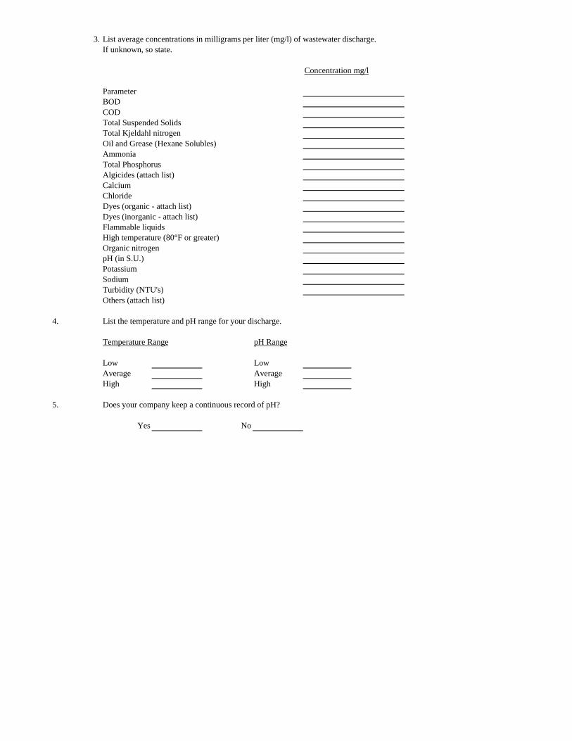
3. List average concentrations in milligrams per liter (mg/l) of wastewater discharge.If unknown, so state.
Concentration mg/l
ParameterBODCODTotal Suspended SolidsTotal Kjeldahl nitrogenOil and Grease (Hexane Solubles)AmmoniaTotal PhosphorusAlgicides (attach list)CalciumChlorideDyes (organic - attach list)Dyes (inorganic - attach list)Flammable liquidsHigh temperature (80°F or greater)Organic nitrogenpH (in S.U.)PotassiumSodiumTurbidity (NTU's)Others (attach list)
4. List the temperature and pH range for your discharge.
Temperature Range pH Range
Low LowAverage AverageHigh High
5. Does your company keep a continuous record of pH?
Yes No
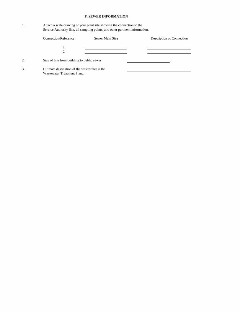
1. Attach a scale drawing of your plant site showing the connection to theService Authority line, all sampling points, and other pertinent information.
2. Size of line from building to public sewer .
3. Ultimate destination of the wastewater is theWastewater Treatment Plant.
F. SEWER INFORMATION
12
Sewer Main Size Description of ConnectionConnection/Reference
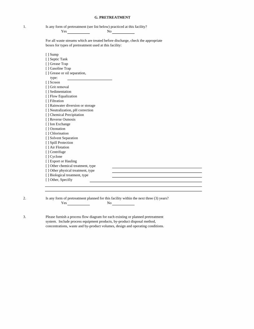
1. Is any form of pretreatment (see list below) practiced at this facility?Yes No
For all waste streams which are treated before discharge, check the appropriateboxes for types of pretreatment used at this facility:
[ ] Sump[ ] Septic Tank[ ] Grease Trap[ ] Gasoline Trap[ ] Grease or oil separation, type:[ ] Screen[ ] Grit removal[ ] Sedimentation[ ] Flow Equalization[ ] Filtration[ ] Rainwater diversion or storage[ ] Neutralization, pH correction[ ] Chemical Precipitation[ ] Reverse Osmosis[ ] Ion Exchange[ ] Ozonation[ ] Chlorination[ ] Solvent Separation[ ] Spill Protection[ ] Air Flotation[ ] Centrifuge[ ] Cyclone[ ] Export or Hauling[ ] Other chemical treatment, type[ ] Other physical treatment, type[ ] Biological treatment, type[ ] Other, Specifiy
2. Is any form of pretreatment planned for this facility within the next three (3) years?Yes No
3. Please furnish a process flow diagram for each existing or planned pretreatmentsystem. Include process equipment products, by-product disposal method,concentrations, waste and by-product volumes, design and operating conditions.
G. PRETREATMENT
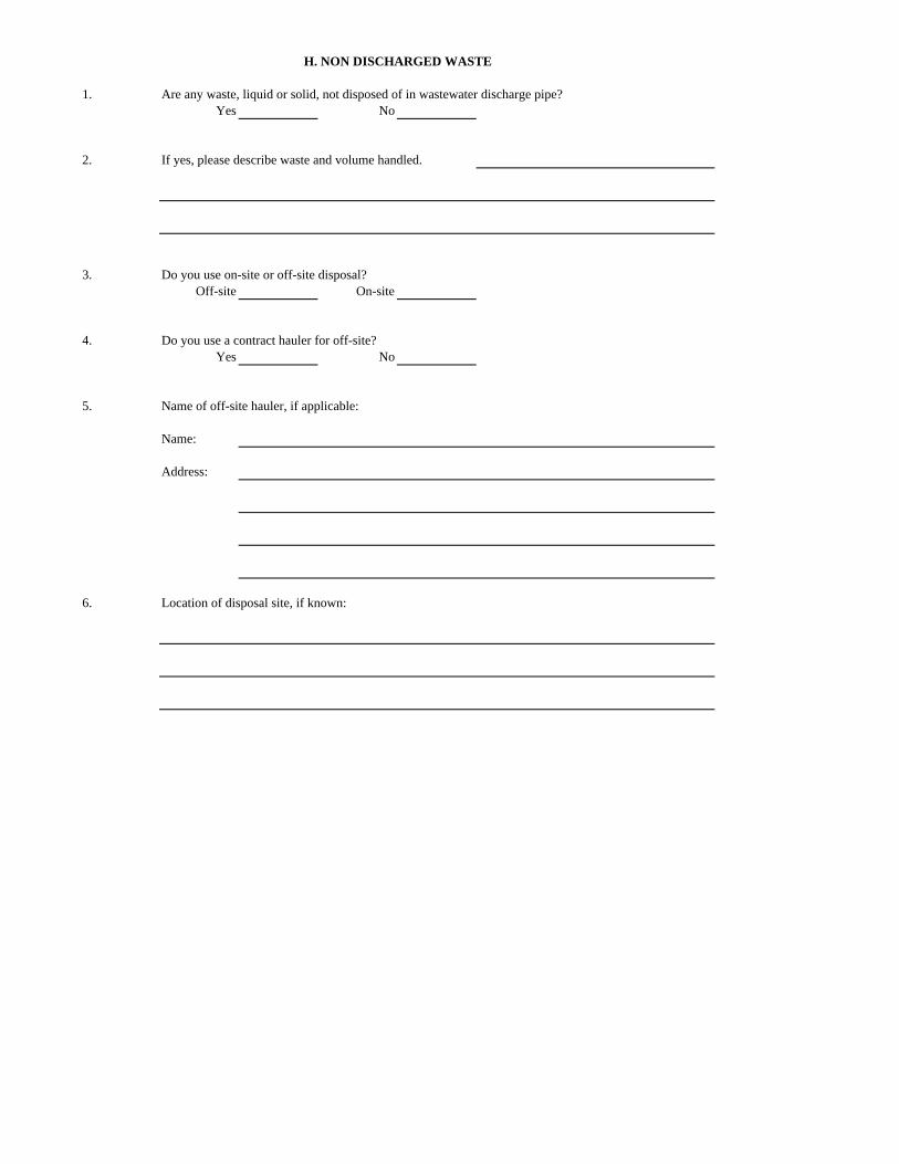
1. Are any waste, liquid or solid, not disposed of in wastewater discharge pipe?Yes No
2. If yes, please describe waste and volume handled.
3. Do you use on-site or off-site disposal?Off-site On-site
4. Do you use a contract hauler for off-site?Yes No
5. Name of off-site hauler, if applicable:
Name:
Address:
6. Location of disposal site, if known:
H. NON DISCHARGED WASTE

Appendix B
Industrial Wastewater Discharge Permit
INDUSTRIAL WASTEWATER DISCHARGE PERMIT Permit Number Effective Date Expiration Date Amended Date
AUTHORIZATION TO DISCHARGE UNDER
THE INDUSTRIAL WASTE PRETREATMENT PROGRAM OF THE SERVICE AUTHORITY
DATED _____________ 1. Pursuant to the Augusta County Service Authority Rules and Regulations for Wastewater Discharge
________________ located at __________________ is authorized to discharge to __________t Wastewater Treatment Plant in accordance with the effluent limitations, monitoring requirements, and other conditions set forth in this permit.
2. Pretreatment and/or discharge of all industrial waste shall be in accordance with this permit. 3. The issuance of this permit does not relieve the permittee of the responsibility of operating the
facility in a reliable and consistent manner as per the conditions of the permit. If violations, deficiencies, design flows or operational problems are identified which affect the performance, reliability or effluent quality, it shall be the responsibility of the permittee to correct such deficiencies as may be directed by the Service Authority.
4. By accepting this permit the permittee acknowledges that this permit is subject to all present and
future Rules and Regulations of Augusta County Service Authority and permittee will abide with said Rules and Regulations.
_______________________________ Kenneth J. Fanfoni, P. E. Executive Director Augusta County Service Authority Date
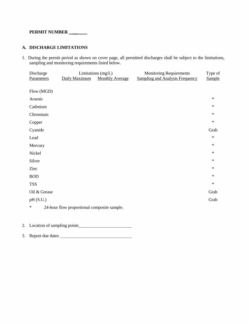
PERMIT NUMBER __ A. DISCHARGE LIMITATIONS 1. During the permit period as shown on cover page, all permitted discharges shall be subject to the limitations,
sampling and monitoring requirements listed below.
Discharge Limitations (mg/L) Monitoring Requirements Type of Parameters Daily Maximum Monthly Average Sampling and Analysis Frequency Sample
Flow (MGD)
Arsenic *
Cadmium *
Chromium *
Copper *
Cyanide Grab
Lead *
Mercury *
Nickel *
Silver *
Zinc *
BOD *
TSS *
Oil & Grease Grab
pH (S.U.) Grab
* 24-hour flow proportional composite sample.
2. Location of sampling points 3. Report due dates
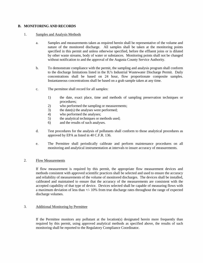
B. MONITORING AND RECORDS 1. Samples and Analysis Methods a. Samples and measurements taken as required herein shall be representative of the volume and
nature of the monitored discharge. All samples shall be taken at the monitoring points specified in this permit and unless otherwise specified, before the effluent joins or is diluted by other waste streams, body of water or substances. Monitoring points shall not be changed without notification to and the approval of the Augusta County Service Authority.
b. To demonstrate compliance with the permit, the sampling and analysis program shall conform
to the discharge limitations listed in the IU's Industrial Wastewater Discharge Permit. Daily concentrations shall be based on 24 hour, flow proportionate composite samples. Instantaneous concentrations shall be based on a grab sample taken at any time.
c. The permittee shall record for all samples: 1) the date, exact place, time and methods of sampling preservation techniques or
procedures; 2) who performed the sampling or measurements; 3) the date(s) the analyses were performed; 4) who performed the analyses; 5) the analytical techniques or methods used; 6) and the results of such analyses. d. Test procedures for the analysis of pollutants shall conform to those analytical procedures as
approved by EPA as listed in 40 C.F.R. 136. e. The Permittee shall periodically calibrate and perform maintenance procedures on all
monitoring and analytical instrumentation at intervals to insure accuracy of measurements. 2. Flow Measurements If flow measurement is required by this permit, the appropriate flow measurement devices and
methods consistent with approved scientific practices shall be selected and used to ensure the accuracy and reliability of measurements of the volume of monitored discharges. The devices shall be installed, calibrated and maintained to ensure that the accuracy of the measurements are consistent with the accepted capability of that type of device. Devices selected shall be capable of measuring flows with a maximum deviation of less than +/- 10% from true discharge rates throughout the range of expected discharge volumes.
3. Additional Monitoring by Permittee If the Permittee monitors any pollutant at the location(s) designated herein more frequently than
required by this permit, using approved analytical methods as specified above, the results of such monitoring shall be reported to the Regulatory Compliance Coordinator.
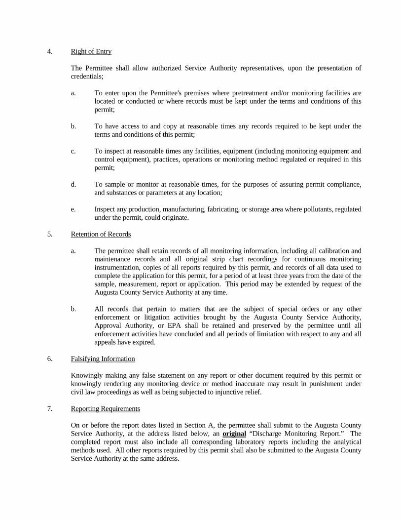
4. Right of Entry The Permittee shall allow authorized Service Authority representatives, upon the presentation of
credentials; a. To enter upon the Permittee's premises where pretreatment and/or monitoring facilities are
located or conducted or where records must be kept under the terms and conditions of this permit;
b. To have access to and copy at reasonable times any records required to be kept under the
terms and conditions of this permit; c. To inspect at reasonable times any facilities, equipment (including monitoring equipment and
control equipment), practices, operations or monitoring method regulated or required in this permit;
d. To sample or monitor at reasonable times, for the purposes of assuring permit compliance,
and substances or parameters at any location; e. Inspect any production, manufacturing, fabricating, or storage area where pollutants, regulated
under the permit, could originate. 5. Retention of Records a. The permittee shall retain records of all monitoring information, including all calibration and
maintenance records and all original strip chart recordings for continuous monitoring instrumentation, copies of all reports required by this permit, and records of all data used to complete the application for this permit, for a period of at least three years from the date of the sample, measurement, report or application. This period may be extended by request of the Augusta County Service Authority at any time.
b. All records that pertain to matters that are the subject of special orders or any other
enforcement or litigation activities brought by the Augusta County Service Authority, Approval Authority, or EPA shall be retained and preserved by the permittee until all enforcement activities have concluded and all periods of limitation with respect to any and all appeals have expired.
6. Falsifying Information Knowingly making any false statement on any report or other document required by this permit or
knowingly rendering any monitoring device or method inaccurate may result in punishment under civil law proceedings as well as being subjected to injunctive relief.
7. Reporting Requirements On or before the report dates listed in Section A, the permittee shall submit to the Augusta County
Service Authority, at the address listed below, an original “Discharge Monitoring Report.” The completed report must also include all corresponding laboratory reports including the analytical methods used. All other reports required by this permit shall also be submitted to the Augusta County Service Authority at the same address.
Regulatory Compliance Coordinator Augusta County Service Authority P.O. Box 859 Verona, Virginia 24482 C. GENERAL REQUIREMENTS 1. Severability The provisions of this permit are severable, and if any provision of this permit, or the application of
any provision of this permit to any circumstance, is held invalid, the application of such provision to other circumstances, and the remainder of this permit, shall not be affected thereby.
2. Duty to Comply The permittee must comply with all conditions of this permit. Failure to comply with the
requirements of these regulations may be grounds for administrative action, or enforcement proceedings including civil penalties, injunctive relief, and summary abatements.
3. Duty to Mitigate The permittee shall take all reasonable steps to minimize or correct any adverse impact on the
environment resulting from noncompliance with this permit, including such accelerated or additional monitoring as necessary to determine the nature and impact of the non-complying discharge.
4. Permit Modification and Revocation This permit may be modified, revoked and reissued, or terminated in whole or in part during its term
for cause including, but not limited to, the following: a. to incorporate any new or revised Federal, State, or local pretreatment standards or
requirements; b. material or substantial alterations or additions to the dischargers operation which were not
covered in the effective permit; c. A change in any condition that requires either a temporary or permanent reduction or
elimination of the authorized discharge; d. Information indicating that the permitted discharge poses a threat to the Augusta County
Service Authority's collection and treatment systems, POTW personnel or the receiving waters;
e. Materials damaging to sewer lines or treatment process are released by the Permittee to the
sewer, causing deterioration of these structures or interfering with proper conveyance and treatment of wastewater;
f. The effluent from the wastewater treatment plant is no longer of a quality permitted for discharge to a watercourse, and it is found that the Permittee is delivering wastes to the wastewater system, that, due to (1) significant non-compliance, as defined in the Authority’s Rules and Regulations for Wastewater Discharge, with the permit or (2) a material change in the composition or volume of the Permittee’s waste stream cannot be sufficiently treated or require pretreatment; or
g. The Permittee 1) discharges wastewater that is in significant non-compliance of the permit issued; 2) fails to pay user charges for public sewer services when due; 3) discharges prohibited wastes to public sewers; or 4) violates any requirement of these Rules and Regulations The filing of a request by the permittee for a permit modification, revocation and reissuance, or
termination, or notification of planned changes or anticipated noncompliance, does not stay any permit conditions.
5. Duty to Reapply At least 90 days prior to the expiration date of this permit, unless permission for a later date has been
granted, the permittee shall submit a new application for a permit 6. Property Rights The issuance of this permit does not convey any Property rights in either real or personal property, or
any exclusive privileges, nor does it authorize any injury to private property or any invasion of personal rights, nor any infringement of Federal, State, or local laws or regulations.
7. Transfer of Ownership or Control Wastewater discharge permits are issued to a specific user for a specific operation and are not
assignable to another user or transferable to any other location without the prior written approval of the Augusta County Service Authority. In the event of sale, the permittee must inform the purchaser of all responsibilities and obligations under this permit.
8. Dilution The permittee shall not increase the use of potable or process water or, in any way, attempt to dilute a
discharge as a partial or complete substitute for adequate treatment to achieve compliance with the limitations contained in this permit.
9. Adverse Impact The Permittee shall take all reasonable steps to minimize any adverse impact to the receiving works
resulting from noncompliance with any effluent limitations specified in this permit, including such accelerated or additional monitoring as necessary to determine the nature and impact of the non-complying discharge. The permittee shall immediately notify the Augusta County Service Authority
of slug discharges, spills that may enter the public sewer, or any other significant changes in operations, wastewater characteristics, and constituents.
10. General Prohibitive Standards The permittee shall comply with all the general and specific prohibitive discharge standards in Section
4 of the Augusta County Service Authority Rules and Regulations for Wastewater Discharge. 11. Confidentiality of Information The Augusta County Service Authority shall not at any time disclose to any person other than the
appropriate officials of the Virginia Department of Environmental Quality or the U. S. Environmental Protection Agency pursuant to the requirements of the Clean Water Act, any secret formula, secret processes, or secret methods properly identified and denoted as such. Trade secrets transmitted by the Augusta County Service Authority to the Virginia Department of Environmental Quality or the U.S. Environmental Protection Agency, would be marked as such by the Authority, and will be subject to the appropriate Federal regulations governing confidentiality of such information. At no time can wastewater effluent data be claimed as confidential information.
12. Administrative Continuance If the permittee has reapplied for permission to discharge within the specified time period and a new
permit has not been issued before expiration date of current permit, then the current permit is in effect for up to 180 days after the expiration date.
D. OPERATION AND MAINTENANCE OF POLLUTION CONTROLS 1. Proper Operation and Maintenance The permittee shall at all times properly operate and maintain all facilities and systems of treatment
and control (and related appurtenances) which are installed or used by the permittee to achieve compliance with the conditions of this permit. Proper operation and maintenance includes but is not limited to: effective performance, adequate funding, adequate operator staffing and training, and adequate laboratory, and process controls, including assurance procedures. This provision requires the operation of back-up or auxiliary facilities or similar systems only when necessary to achieve compliance with the conditions of this permit.

2. Duty to Halt or Reduce Activity Upon reduction, loss, or failure of the treatment facility, the permittee shall, to the extent necessary to
maintain compliance with its permit, control production or all discharges or both until operation of the treatment facility is restored or an alternative method of treatment is provided. This requirement applies, for example, when the primary source of power of the treatment facility fails or is reduced. It shall not be a defense for a permittee in an enforcement action that it would have been necessary to halt or reduce the permitted activity in order to maintain compliance with the conditions of this permit.
3. Bypass of Treatment Facilities a. Bypass is prohibited unless it is unavoidable to prevent loss of life, personal injury or severe
property damage or no feasible alternatives exist. b. Bypass not exceeding limitations. The permittee may allow bypass to occur which does not
cause effluent limitations to be exceeded, but only if it also is for essential maintenance to assure efficient operation.
c. Notification of bypass: 1) Anticipated Bypass. If the permittee knows in advance of the need for a bypass, it
shall submit prior written notice, at least 10 days before the date of the bypass to the Augusta County Service Authority, P.O. Box 859, Verona VA 24482
2) Unanticipated bypass. The permittee shall immediately notify the Augusta County
Service Authority and submit a written notice to the POTW within 24 hours of becoming aware of the bypass.
3) Notification of bypass shall contain the following information: a) Description of the discharge or slug load, the cause(s) thereof and the
discharges or slug load's impact on the permittee's noncompliance status; b) Duration of noncompliance, including exact dates and times of
noncompliance, and if the noncompliance continues, the time by which compliance is reasonably expected to occur;
c) All steps taken or to be taken to reduce, eliminate and prevent recurrence of
such discharge, slug load or other conditions of noncompliance. 4. Removed Substances Solids, sludge, filter backwash, or other pollutants removed in the course of treatment or control of
waste waters or intake waters shall be disposed of in accordance with section 405 of the Clean Water Act and Subtitles C and D of the Resource Conservation and Recovery Act and shall not enter the public transport/treatment works.
E. ADDITIONAL REPORTING REQUIREMENTS 1. Change in Discharge The permittee shall give notice to the Augusta County Service Authority 90 days prior to any facility
expansion, production increase, or process modifications which results in new or substantially increased discharges or a change in the nature of the discharge.
a. If such changes will not violate the discharge limitations, specified in this permit, the permit
may be modified to specify and limit any pollutants not previously limited. b. If such changes violate the discharge limitations, specified in this permit, this permit will
become void and a new permit application must be submitted 2. Anticipated Noncompliance The permittee shall give advance notice to the Augusta County Service Authority of any planned
changes in the permitted facility or activity which may result in noncompliance with permit requirements.
3. Duty to Provide Information The permittee shall furnish to the Augusta County Service Authority, within a reasonable time, any
information which the Augusta County Service Authority may request to determine whether cause exists for modifying, revoking and reissuing, or terminating this permit, or to determine compliance with this permit. The permittee shall also furnish to the Augusta County Service Authority, upon request, copies of records required to be kept by this permit.
4. Signatory Requirements All applications, reports or information submitted to the Augusta County Service Authority shall be
signed and certified as follows: a. All permit applications shall be signed: 1) For a corporation: by a principal executive officer of a least the level of vice-
president; 2) for a partnership or sole proprietorship: by a general partner or the proprietor,
respectively. b. All other correspondence, reports and self-monitoring reports shall be signed by a person
described above or by a duly authorized representative of that person. A person is a duly authorized representative only if:
1) The authorization is made in writing by a person described in a. above; or 2) The authorization specifies either an individual or a position having responsibility for
the overall operation of the regulated facility or activity, such as the position of plant manager, superintendent, or position of equivalent responsibility.
c. Certification. Any person signing a document under this section shall make the following
certification: "I certify under penalty of law that this document and all attachments were prepared under my
direction or supervision in accordance with a system designed to assure that qualified personnel properly gathered and evaluated the information submitted. Based on my inquiry of the person or persons who managed the system, or those persons directly responsible for gathering the information, the information submitted is to the best of my knowledge and belief, true, accurate and complete. I am aware that there are significant penalties for submitting false information, including the possibility of a civil penalty for knowing violation."
d. Any change in signatures shall be submitted to the Augusta County Service Authority in
writing within 30 days after the change. 5. Reporting of Accidental Discharges or Slug Load The user responsible for any accidental or detrimental discharge or slug load to a wastewater treatment
system must notify the Authority by the following methods: a. Telephone Notification: Any user causing or suffering any discharge whether accidental or
not, which presents or may present an eminent or substantial endangerment to the health, and welfare of persons, to the environment, or which is likely to cause interference with the wastewater treatment system serving the user, shall notify the Authority immediately by telephone.
b. Written Report: Within 24 hours following such occurrence, the user shall provide the
Authority with a detailed written report describing the cause of the accidental discharge or slug load and corrective measures taken by the user. Such notification shall not relieve the user of any expense, loss, or damage to the Authority's wastewater treatment system, fish kills, or any other damage to person or property; nor shall such notification relieve the user of any fines, civil penalties, or other liability which may be imposed by the Rules and Regulations or other applicable law. The written report shall specify:
1) Description of the discharge or slug load, the cause(s) thereof and the upsets or slug
load's impact on the permittee's noncompliance status; 2) Duration of noncompliance, including exact dates and times of noncompliance, and if
the noncompliance continues, the time by which compliance is reasonable expected to occur;
3) All steps taken or to be taken to reduce, eliminate and prevent recurrence of such an
upset, slug load or other conditions of noncompliance.
A documented and verified operating upset shall be an affirmative defense to any enforcement action brought against the permittee for violations attributable to the upset event.
c. Notice to Employees: A notice shall be permanently posted on the user's bulletin board or
other prominent location advising employees whom to call in the event of dangerous discharge. Employers shall insure that all employees who would be responsible to make calls and take appropriate actions if such a dangerous discharge were to occur are advised of the "emergency notification procedure."
6. Reporting Requirements for Known Violations Other Than Accidental Discharge If for any reason the Permittee does not comply with the limitations of this permit, the Permittee shall
notify the Authority immediately by telephone and follow in writing within five (5) days a description of the violations and the reason or explanation for said violations. The written notification shall also address the steps taken to assure compliance and to eliminate chance of reoccurrence. The Permittee shall resample, retest, and submit new test results within 30 days of becoming aware of violation.
F. OTHER CONDITIONS 1. State and Federal Laws Nothing in this permit shall be construed to preclude the institution of any legal action or relieve the
Permittee from any responsibilities, liabilities, or penalties to which the Permittee is or may be subject to under any applicable State or Federal Law.
2. Special Conditions Special conditions (Section H of this Permit) may be added to this permit at any time by the Executive
Director of the Augusta County Service Authority. Special conditions may consist of compliance schedules in regard to pretreatment of the Permittee's waste stream.
3. Appeals The Permittee has the right to appeal enforcement actions as outlined in this Permit. Notice of appeal
should be given in writing to the Executive Director of the Service Authority within thirty (30) days of the Director's order. Failure to file within time limit shall be considered a waiver in right to appeal. Three members of the Authority shall be appointed to serve as the Appeals Committee.
4. Termination of Service Water and/or sewer service to the Permittee may be terminated when: a. Materials damaging to sewer lines or treatment process are released by the Permittee to the
sewer, causing deterioration of these structures or interfering with proper conveyance and treatment of wastewater;
b. The effluent from the wastewater treatment plant is no longer of a quality permitted for
discharge to a watercourse, and it is found that the Permittee is delivering wastes to the wastewater system, that, due to (1) significant non-compliance, as defined in the Authority’s Rules and Regulations for Wastewater Discharge, with the permit or (2) a material change in
the composition or volume of the Permittee’s waste stream cannot be sufficiently treated or require pretreatment; or
c. The Permittee 1) discharges wastewater that is in significant non-compliance of the permit issued; 2) fails to pay user charges for public sewer services when due; 3) discharges prohibited wastes to public sewers; or 4) violates any requirement of the Rules and Regulations. The Executive Director will endeavor within reasonable limits to eliminate or remedy violation
without resorting to termination of the Permittee's service. However, if those efforts have been unsuccessful, the Executive Director is authorized to terminate service to a Permittee.
The Executive Director shall not terminate service to a Permittee without first delivering to the
Permittee written notice of such proposed termination. The notice shall state the reason or reasons of said termination and may allow a reasonable time for satisfactory compliance to meet the wastewater constituents and/or characteristic limitation(s) that are being violated.
Nothing in this permit is intended to deter, hinder or stop the Service Authority personnel from taking
immediate action to terminate service to a Permittee when there is imminent risk of great danger to the wastewater facilities.
G. FEES, CHARGES, SURCHARGES, AND CIVIL LIABILITY 1. Regular Service Charge The Permittee shall pay all water and sewer charges on a prompt basis as bills are received and in
accordance with Service Authority Policy. 2. Permitting Fees When submitting an Application for Discharge Permit, the applicant shall also pay a permit fee based
upon the applicant's expected or actual wastewater discharge rate. A fee of $100 shall be paid for all applicants up to a flow of 10,000 gallons per day. Thereafter the applicant shall pay $50 for each 5,000 gallons per day flow increment over 10,000 gpd (e.g., an applicant's wastewater discharge rate is 29,500 gallons per day. The application fee is $300).
3. Surcharge As a result of violations in permit limits for compatible pollutants, the permittee shall be responsible
for surcharges described as follows: a. BOD and TSS: The permittee shall pay $.30/pound for discharges over permitted limits. b. Oils and Grease: The permittee shall pay for the cost of disposal for oil and grease discharges
over permitted limits. c. pH: The permittee shall pay for the cost of restoring the wastewater treatment plant and
facilities to normal operations. The Permittee shall be responsible for any other special surcharges that may be described in this
permit. 4. Civil Liability Any user who violates any provision of the Rules and Regulations or any condition or limitation of a
Permit, or plan approval related thereto, shall be financially responsible and liable to the Authority, in addition to normal service charges and surcharges, for all costs incurred by the Authority associated with the violation of the Rules and Regulations, including, but not limited to the following:
a. Cost of mileage and labor incurred in detecting and correcting the violation. b. Laboratory analysis costs associated with detecting and correcting the violation. c. Additional treatment costs caused by the violation or associated with detecting and correcting
the violation.
d. Costs of any additional equipment acquired or expended by the Authority for detecting or correcting the violation.
e. Repair and/or replacement of any part of the sewage system damaged by the violation. f. Any liability, damages, fines, or civil penalties incurred as a result of the violation. g. Other costs as are associated with the detecting and correcting of the violations. In addition, any user who violates any provision of the Rules and Regulations or any order or permit
issued under the Rules and Regulations shall be liable for a civil penalty of up to $1000.00 per day per violation.
H. SPECIAL CONDITIONS

Appendix C
Fishersville Regional Wastewater Facility VA0025291
Compatible Pollutants
Incompatible Pollutants (Local Limits)
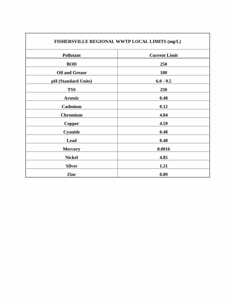
FISHERSVILLE REGIONAL WWTP LOCAL LIMITS (mg/L)
Pollutant Current Limit
BOD 250
Oil and Grease 100
pH (Standard Units) 6.0 - 9.5
TSS 250
Arsenic 0.48
Cadmium 0.12
Chromium 4.84
Copper 4.59
Cyanide 0.48
Lead 0.48
Mercury 0.0016
Nickel 4.85
Silver 1.21
Zinc 0.89

Appendix D
Middle River Regional Wastewater Facility VA0064793
Compatible Pollutants
Incompatible Pollutants (Local Limits)
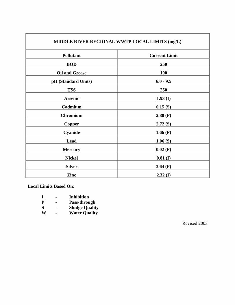
MIDDLE RIVER REGIONAL WWTP LOCAL LIMITS (mg/L)
Pollutant Current Limit
BOD 250
Oil and Grease 100
pH (Standard Units) 6.0 - 9.5
TSS 250
Arsenic 1.93 (I)
Cadmium 0.15 (S)
Chromium 2.88 (P)
Copper 2.72 (S)
Cyanide 1.66 (P)
Lead 1.06 (S)
Mercury 0.02 (P)
Nickel 0.81 (I)
Silver 3.64 (P)
Zinc 2.32 (I)
Local Limits Based On: I - Inhibition P - Pass-through S - Sludge Quality W - Water Quality
Revised 2003

Appendix E
Mt. Sidney Wastewater Facility VA0022322
Compatible Pollutants
Incompatible Pollutants (Local Limits)
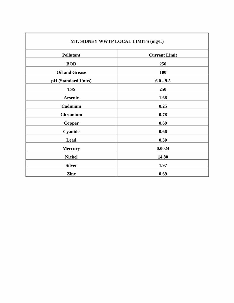
MT. SIDNEY WWTP LOCAL LIMITS (mg/L)
Pollutant Current Limit
BOD 250
Oil and Grease 100
pH (Standard Units) 6.0 - 9.5
TSS 250
Arsenic 1.68
Cadmium 0.25
Chromium 0.78
Copper 0.69
Cyanide 0.66
Lead 0.30
Mercury 0.0024
Nickel 14.80
Silver 1.97
Zinc 0.69

Appendix F
Stuarts Draft Wastewater Facility VA0066877
Compatible Pollutants
Incompatible Pollutants (Local Limits)
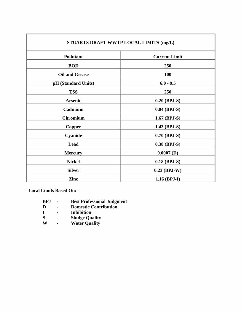
STUARTS DRAFT WWTP LOCAL LIMITS (mg/L)
Pollutant Current Limit
BOD 250
Oil and Grease 100
pH (Standard Units) 6.0 - 9.5
TSS 250
Arsenic 0.20 (BPJ-S)
Cadmium 0.04 (BPJ-S)
Chromium 1.67 (BPJ-S)
Copper 1.43 (BPJ-S)
Cyanide 0.70 (BPJ-S)
Lead 0.38 (BPJ-S)
Mercury 0.0007 (D)
Nickel 0.18 (BPJ-S)
Silver 0.23 (BPJ-W)
Zinc 1.16 (BPJ-I)
Local Limits Based On: BPJ - Best Professional Judgment D - Domestic Contribution I - Inhibition S - Sludge Quality W - Water Quality

Appendix G
Weyers Cave Wastewater Facility VA0022349
Compatible Pollutants
Incompatible Pollutants (Local Limits)
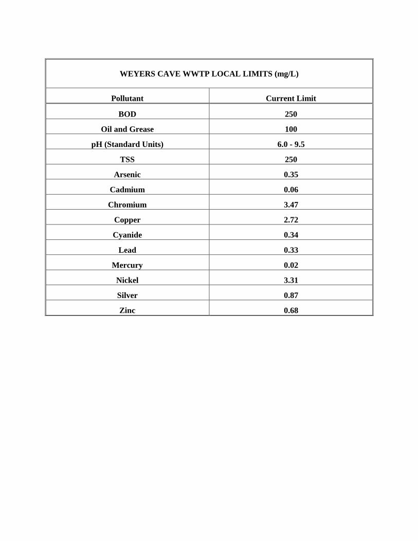
WEYERS CAVE WWTP LOCAL LIMITS (mg/L)
Pollutant Current Limit
BOD 250
Oil and Grease 100
pH (Standard Units) 6.0 - 9.5
TSS 250
Arsenic 0.35
Cadmium 0.06
Chromium 3.47
Copper 2.72
Cyanide 0.34
Lead 0.33
Mercury 0.02
Nickel 3.31
Silver 0.87
Zinc 0.68

Appendix H
Notice of Violation
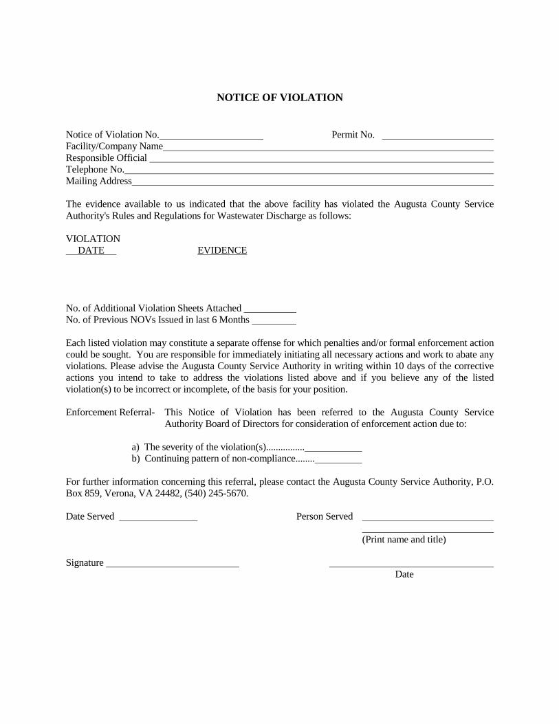
NOTICE OF VIOLATION Notice of Violation No. Permit No. Facility/Company Name Responsible Official Telephone No. Mailing Address The evidence available to us indicated that the above facility has violated the Augusta County Service Authority's Rules and Regulations for Wastewater Discharge as follows: VIOLATION DATE EVIDENCE No. of Additional Violation Sheets Attached No. of Previous NOVs Issued in last 6 Months Each listed violation may constitute a separate offense for which penalties and/or formal enforcement action could be sought. You are responsible for immediately initiating all necessary actions and work to abate any violations. Please advise the Augusta County Service Authority in writing within 10 days of the corrective actions you intend to take to address the violations listed above and if you believe any of the listed violation(s) to be incorrect or incomplete, of the basis for your position. Enforcement Referral- This Notice of Violation has been referred to the Augusta County Service
Authority Board of Directors for consideration of enforcement action due to: a) The severity of the violation(s)................ b) Continuing pattern of non-compliance........ For further information concerning this referral, please contact the Augusta County Service Authority, P.O. Box 859, Verona, VA 24482, (540) 245-5670. Date Served Person Served (Print name and title) Signature Date

Appendix I
Administrative Show Cause Order
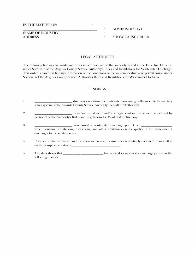
IN THE MATTER OF: * ___________________________________________ * ADMINISTRATIVE (NAME OF INDUSTRY) * ADDRESS: * SHOW CAUSE ORDER LEGAL AUTHORITY The following findings are made and order issued pursuant to the authority vested in the Executive Director, under Section 7 of the Augusta County Service Authority's Rules and Regulations for Wastewater Discharge. This order is based on findings of violation of the conditions of the wastewater discharge permit issued under Section 3 of the Augusta County Service Authority's Rules and Regulations for Wastewater Discharge. FINDINGS 1. ______________________ discharges nondomestic wastewater containing pollutants into the sanitary
sewer system of the Augusta County Service Authority (hereafter, "Authority"). 2. ______________________ is an "industrial user" and/or a "significant industrial user" as defined by
Section 2 of the Authority's Rules and Regulations for Wastewater Discharge. 3. ______________________ was issued a wastewater discharge permit on __________________
which contains prohibitions, restrictions, and other limitations on the quality of the wastewater it discharges to the sanitary sewer.
4. Pursuant to the ordinance and the above-referenced permit, data is routinely collected or submitted
on the compliance status of____________________________. 5. The data shows that _______________________ has violated its wastewater discharge permit in the
following manner:
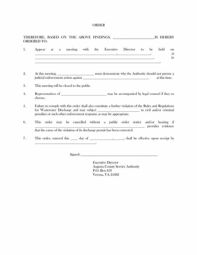
ORDER THEREFORE, BASED ON THE ABOVE FINDINGS, ________________________IS HEREBY ORDERED TO: 1. Appear at a meeting with the Executive Director to be held on
_______________________________________________,___________________, at ____________________________________________________________________, in ________________________________________________________________________.
2. At this meeting, _____________________ must demonstrate why the Authority should not pursue a
judicial enforcement action against ______________________________________ at this time. 3. This meeting will be closed to the public. 4. Representatives of __________________________ may be accompanied by legal counsel if they so
choose. 5. Failure to comply with this order shall also constitute a further violation of the Rules and Regulations
for Wastewater Discharge and may subject ________________________ to civil and/or criminal penalties or such other enforcement response as may be appropriate.
6. This order may be cancelled without a public order notice and/or hearing if
_______________________________________________________________ provides evidence that the cause of the violation of its discharge permit has been corrected.
7. This order, entered this ____ day of _____________,______, shall be effective upon receipt by
___________________________________.
Signed: ____________________________________________ Executive Director Augusta County Service Authority P.O. Box 859 Verona, VA 24482

Appendix J
Administrative Compliance Order
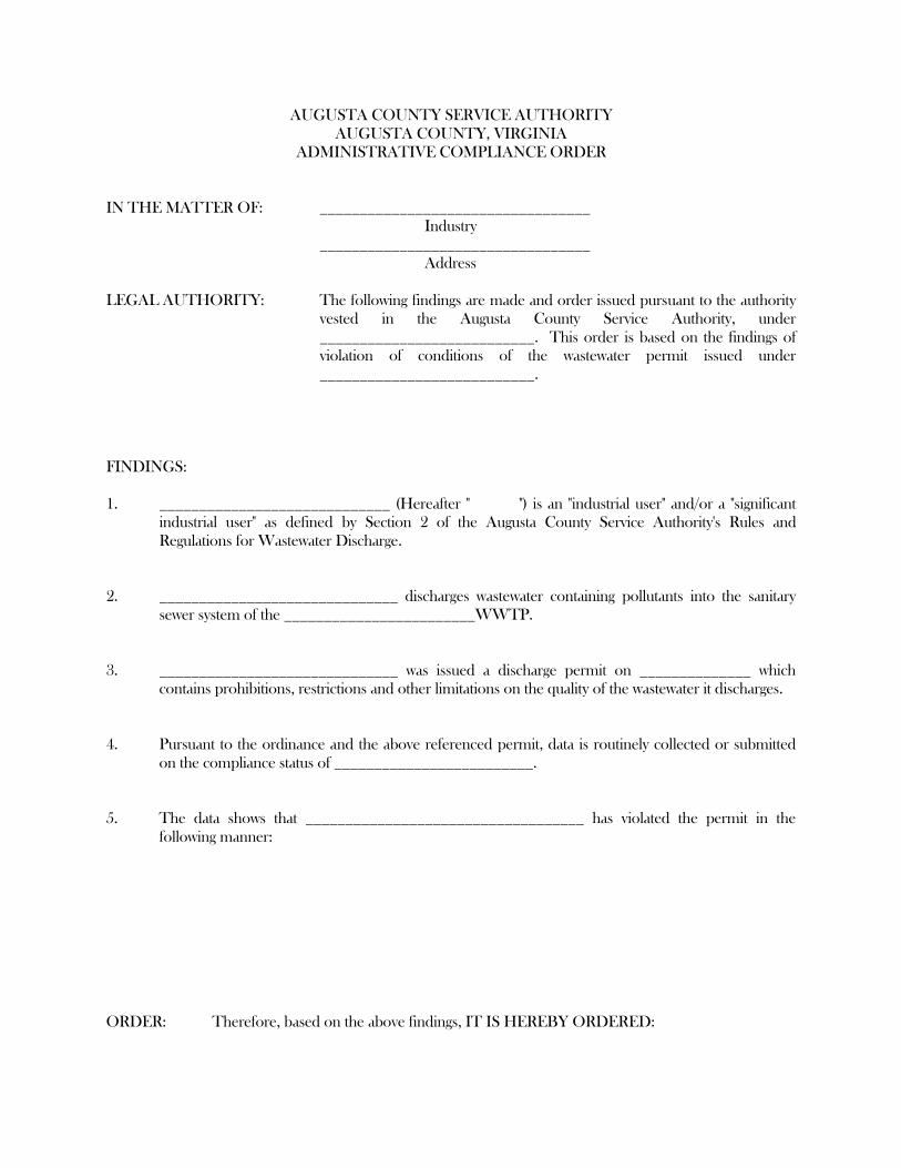
AUGUSTA COUNTY SERVICE AUTHORITY AUGUSTA COUNTY, VIRGINIA ADMINISTRATIVE COMPLIANCE ORDER IN THE MATTER OF: __________________________________ Industry __________________________________ Address LEGAL AUTHORITY: The following findings are made and order issued pursuant to the authority
vested in the Augusta County Service Authority, under ___________________________. This order is based on the findings of violation of conditions of the wastewater permit issued under ___________________________.
FINDINGS: 1. _____________________________ (Hereafter " ") is an "industrial user" and/or a "significant
industrial user" as defined by Section 2 of the Augusta County Service Authority's Rules and Regulations for Wastewater Discharge.
2. ______________________________ discharges wastewater containing pollutants into the sanitary
sewer system of the ________________________WWTP. 3. ______________________________ was issued a discharge permit on ______________ which
contains prohibitions, restrictions and other limitations on the quality of the wastewater it discharges. 4. Pursuant to the ordinance and the above referenced permit, data is routinely collected or submitted
on the compliance status of _________________________. 5. The data shows that ___________________________________ has violated the permit in the
following manner: ORDER: Therefore, based on the above findings, IT IS HEREBY ORDERED:
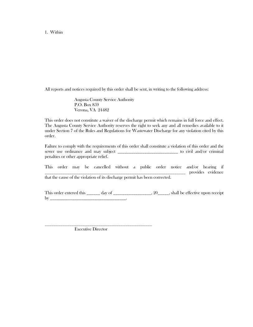
1. Within All reports and notices required by this order shall be sent, in writing to the following address: Augusta County Service Authority P.O. Box 859 Verona, VA 24482 This order does not constitute a waiver of the discharge permit which remains in full force and effect.
The Augusta County Service Authority reserves the right to seek any and all remedies available to it under Section 7 of the Rules and Regulations for Wastewater Discharge for any violation cited by this order.
Failure to comply with the requirements of this order shall constitute a violation of this order and the
sewer use ordinance and may subject ___________________________ to civil and/or criminal penalties or other appropriate relief.
This order may be cancelled without a public order notice and/or hearing if
_______________________________________________________________ provides evidence that the cause of the violation of its discharge permit has been corrected.
This order entered this ______ day of _________________, 20_____, shall be effective upon receipt
by __________________________________. ________________________________________________ Executive Director

Appendix K
Industrial User Inventory
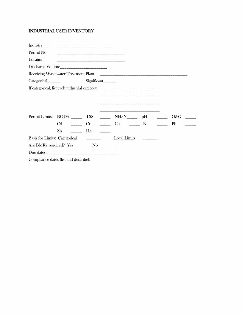
INDUSTRIAL USER INVENTORY
Industry ________________________________
Permit No. ________________________________
Location ________________________________
Discharge Volume______________________
Receiving Wastewater Treatment Plant _________________________________________
Categorical______ Significant______
If categorical, list each industrial category ____________________________
____________________________
____________________________
____________________________
Permit Limits: BOD5 _____ TSS _____ NH3N_____ pH _____ O&G _____
Cd _____ Cr _____ Cu _____ Ni _____ Pb _____
Zn _____ Hg _____
Basis for Limits: Categorical _______ Local Limits _______
Are BMR's required? Yes_______ No________
Due dates:__________________________________
Compliance dates (list and describe):

Appendix L
Compliance Screening Checklist for Monitoring Reports
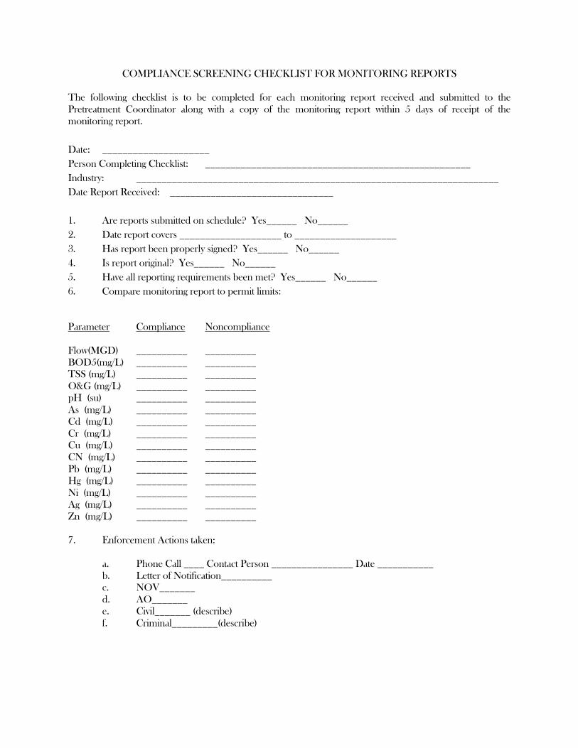
COMPLIANCE SCREENING CHECKLIST FOR MONITORING REPORTS The following checklist is to be completed for each monitoring report received and submitted to the Pretreatment Coordinator along with a copy of the monitoring report within 5 days of receipt of the monitoring report. Date: _____________________ Person Completing Checklist: ____________________________________________________ Industry: _______________________________________________________________________ Date Report Received: ________________________________ 1. Are reports submitted on schedule? Yes______ No______ 2. Date report covers ____________________ to ____________________ 3. Has report been properly signed? Yes______ No______ 4. Is report original? Yes______ No______ 5. Have all reporting requirements been met? Yes______ No______ 6. Compare monitoring report to permit limits: Parameter Compliance Noncompliance Flow(MGD) __________ __________ BOD5(mg/L) __________ __________ TSS (mg/L) __________ __________ O&G (mg/L) __________ __________ pH (su) __________ __________ As (mg/L) __________ __________ Cd (mg/L) __________ __________ Cr (mg/L) __________ __________ Cu (mg/L) __________ __________ CN (mg/L) __________ __________ Pb (mg/L) __________ __________ Hg (mg/L) __________ __________ Ni (mg/L) __________ __________ Ag (mg/L) __________ __________ Zn (mg/L) __________ __________ 7. Enforcement Actions taken: a. Phone Call ____ Contact Person ________________ Date ___________ b. Letter of Notification__________ c. NOV_______ d. AO_______ e. Civil_______ (describe) f. Criminal_________(describe)

Appendix M
Yearly Report
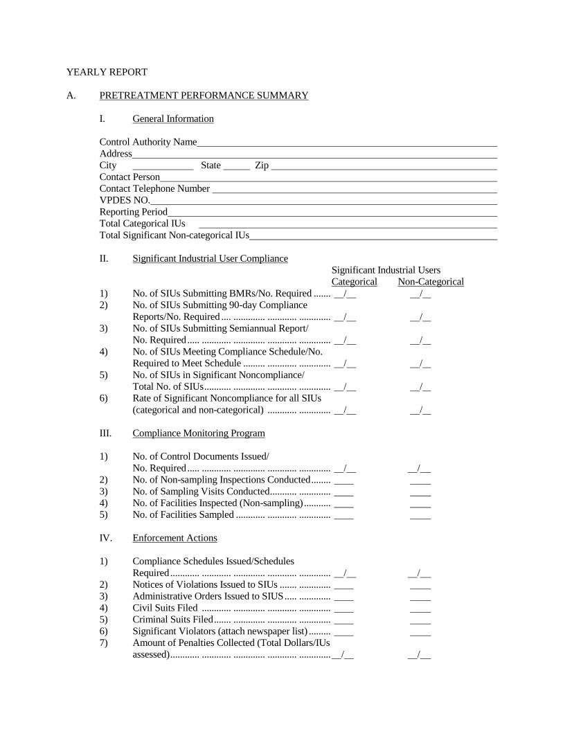
YEARLY REPORT A. PRETREATMENT PERFORMANCE SUMMARY I. General Information Control Authority Name Address City State Zip Contact Person Contact Telephone Number VPDES NO. Reporting Period Total Categorical IUs Total Significant Non-categorical IUs II. Significant Industrial User Compliance Significant Industrial Users Categorical Non-Categorical 1) No. of SIUs Submitting BMRs/No. Required ....... / / 2) No. of SIUs Submitting 90-day Compliance Reports/No. Required .... ............. ............ ............. / / 3) No. of SIUs Submitting Semiannual Report/ No. Required ..... ............ ............. ............ ............. / / 4) No. of SIUs Meeting Compliance Schedule/No. Required to Meet Schedule ......... ............ ............. / / 5) No. of SIUs in Significant Noncompliance/ Total No. of SIUs ........... ............. ............ ............. / / 6) Rate of Significant Noncompliance for all SIUs (categorical and non-categorical) ............ ............. / / III. Compliance Monitoring Program 1) No. of Control Documents Issued/ No. Required ..... ............ ............. ............ ............. / / 2) No. of Non-sampling Inspections Conducted ........ 3) No. of Sampling Visits Conducted ........... ............. 4) No. of Facilities Inspected (Non-sampling) ........... 5) No. of Facilities Sampled ............ ............ ............. IV. Enforcement Actions 1) Compliance Schedules Issued/Schedules Required ............ ............ ............. ............ ............. / / 2) Notices of Violations Issued to SIUs ....... ............. 3) Administrative Orders Issued to SIUS ..... ............. 4) Civil Suits Filed ............ ............. ............ ............. 5) Criminal Suits Filed ....... ............. ............ ............. 6) Significant Violators (attach newspaper list) ......... 7) Amount of Penalties Collected (Total Dollars/IUs assessed) ............ ............ ............. ............ ............. / /

8) Other Actions (sewer bans, etc.).. ............ .............
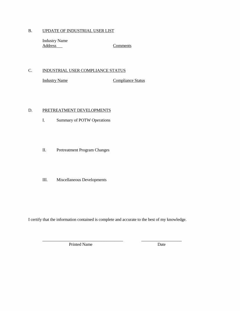
B. UPDATE OF INDUSTRIAL USER LIST Industry Name Address Comments C. INDUSTRIAL USER COMPLIANCE STATUS Industry Name Compliance Status D. PRETREATMENT DEVELOPMENTS I. Summary of POTW Operations II. Pretreatment Program Changes III. Miscellaneous Developments I certify that the information contained is complete and accurate to the best of my knowledge. ______________________________________ ___________________ Printed Name Date

Appendix N
Public Notice of Significant Industrial Pollution Violation(s)

PUBLIC NOTICE OF SIGNIFICANT INDUSTRIAL POLLUTION VIOLATION(S) Listed below are significant industrial wastewater discharge violations of the Augusta County Service Authority Rules and Regulations for Wastewater Discharge occurring over the past twelve months: Industry Name: Address: Violation: Actions taken: Schedule of Compliance: Penalties:

Appendix O
IU Inspection Form
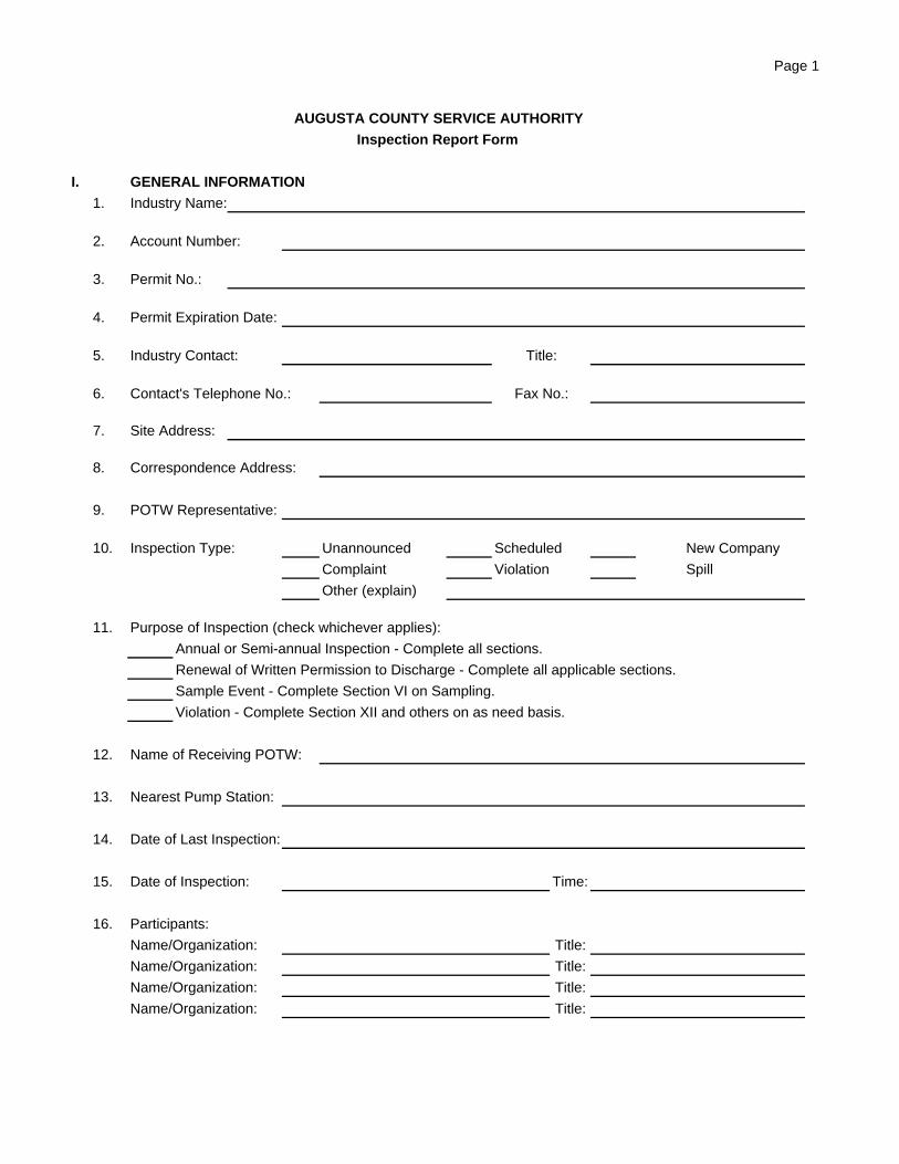
Page 1
AUGUSTA COUNTY SERVICE AUTHORITY
Inspection Report Form
I. GENERAL INFORMATION
1. Industry Name:
2. Account Number:
3. Permit No.:
4. Permit Expiration Date:
5. Industry Contact: Title:
6. Contact's Telephone No.: Fax No.:
7. Site Address:
8. Correspondence Address:
9. POTW Representative:
10. Inspection Type: Unannounced Scheduled New Company
Complaint Violation Spill
Other (explain)
11. Purpose of Inspection (check whichever applies):
Annual or Semi-annual Inspection - Complete all sections.
Renewal of Written Permission to Discharge - Complete all applicable sections.
Sample Event - Complete Section VI on Sampling.
Violation - Complete Section XII and others on as need basis.
12. Name of Receiving POTW:
13. Nearest Pump Station:
14. Date of Last Inspection:
15. Date of Inspection: Time:
16. Participants:
Name/Organization: Title:
Name/Organization: Title:
Name/Organization: Title:
Name/Organization: Title:
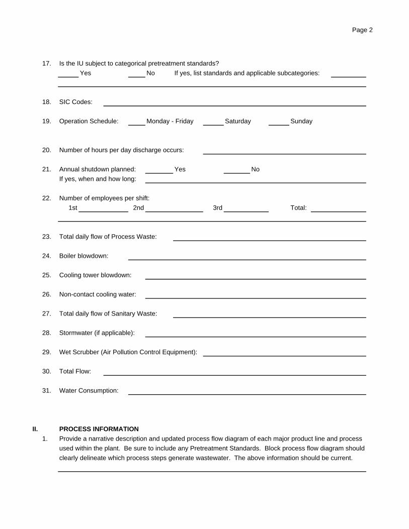
Page 2
17. Is the IU subject to categorical pretreatment standards?
Yes No If yes, list standards and applicable subcategories:
18. SIC Codes:
19. Operation Schedule: Monday - Friday Saturday Sunday
20. Number of hours per day discharge occurs:
21. Annual shutdown planned: Yes No
If yes, when and how long:
22. Number of employees per shift:
1st 2nd 3rd Total:
23. Total daily flow of Process Waste:
24. Boiler blowdown:
25. Cooling tower blowdown:
26. Non-contact cooling water:
27. Total daily flow of Sanitary Waste:
28. Stormwater (if applicable):
29. Wet Scrubber (Air Pollution Control Equipment):
30. Total Flow:
31. Water Consumption:
II. PROCESS INFORMATION
1. Provide a narrative description and updated process flow diagram of each major product line and process
used within the plant. Be sure to include any Pretreatment Standards. Block process flow diagram should
clearly delineate which process steps generate wastewater. The above information should be current.
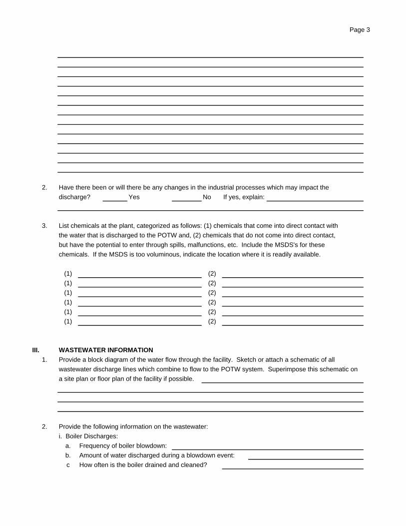
Page 3
2. Have there been or will there be any changes in the industrial processes which may impact the
discharge? Yes No If yes, explain:
3. List chemicals at the plant, categorized as follows: (1) chemicals that come into direct contact with
the water that is discharged to the POTW and, (2) chemicals that do not come into direct contact,
but have the potential to enter through spills, malfunctions, etc. Include the MSDS's for these
chemicals. If the MSDS is too voluminous, indicate the location where it is readily available.
(1) (2)
(1) (2)
(1) (2)
(1) (2)
(1) (2)
(1) (2)
III. WASTEWATER INFORMATION
1. Provide a block diagram of the water flow through the facility. Sketch or attach a schematic of all
wastewater discharge lines which combine to flow to the POTW system. Superimpose this schematic on
a site plan or floor plan of the facility if possible.
2. Provide the following information on the wastewater:
i. Boiler Discharges:
a. Frequency of boiler blowdown:
b. Amount of water discharged during a blowdown event:
c How often is the boiler drained and cleaned?
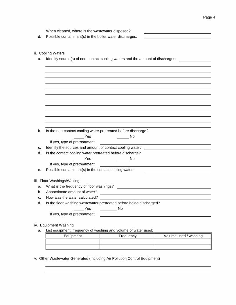
Page 4
When cleaned, where is the wastewater disposed?
d. Possible contaminant(s) in the boiler water discharges:
ii. Cooling Waters
a. Identify source(s) of non-contact cooling waters and the amount of discharges:
b. Is the non-contact cooling water pretreated before discharge?
Yes No
If yes, type of pretreatment:
c. Identify the sources and amount of contact cooling water:
d. Is the contact cooling water pretreated before discharge?
Yes No
If yes, type of pretreatment:
e. Possible contaminant(s) in the contact cooling water:
iii. Floor Washings/Waxing
a. What is the frequency of floor washings?
b. Approximate amount of water?
c. How was the water calculated?
d. Is the floor washing wastewater pretreated before being discharged?
Yes No
If yes, type of pretreatment:
iv. Equipment Washinga. List equipment, frequency of washing and volume of water used:
Equipment Frequency Volume used / washing
v. Other Wastewater Generated (Including Air Pollution Control Equipment)
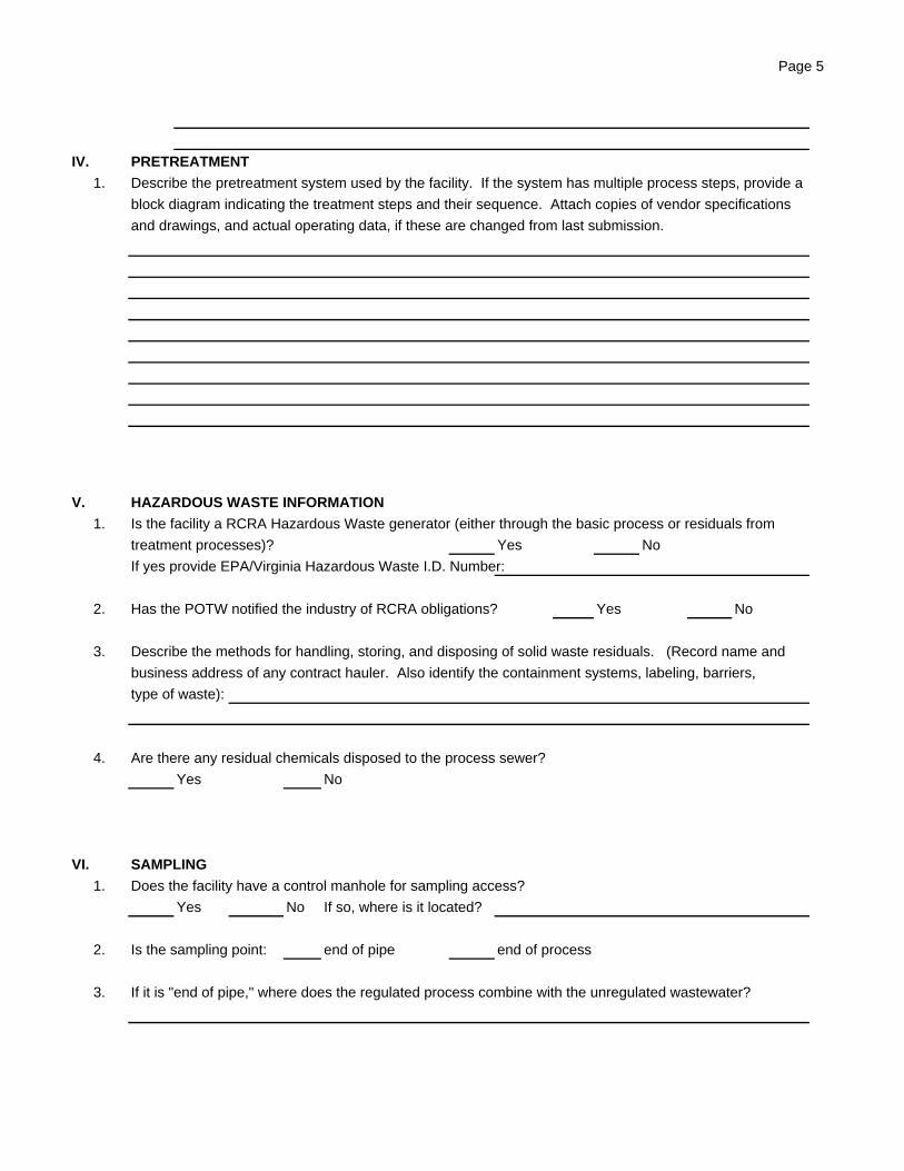
Page 5
IV. PRETREATMENT
1. Describe the pretreatment system used by the facility. If the system has multiple process steps, provide a
block diagram indicating the treatment steps and their sequence. Attach copies of vendor specifications
and drawings, and actual operating data, if these are changed from last submission.
V. HAZARDOUS WASTE INFORMATION
1. Is the facility a RCRA Hazardous Waste generator (either through the basic process or residuals from
treatment processes)? Yes No
If yes provide EPA/Virginia Hazardous Waste I.D. Number:
2. Has the POTW notified the industry of RCRA obligations? Yes No
3. Describe the methods for handling, storing, and disposing of solid waste residuals. (Record name and
business address of any contract hauler. Also identify the containment systems, labeling, barriers,
type of waste):
4. Are there any residual chemicals disposed to the process sewer?
Yes No
VI. SAMPLING
1. Does the facility have a control manhole for sampling access?
Yes No If so, where is it located?
2. Is the sampling point: end of pipe end of process
3. If it is "end of pipe," where does the regulated process combine with the unregulated wastewater?

Page 6
4. Is the final waste stream a combined process waste stream? Yes No If yes, are
the waste streams combined prior to pretreatment? Yes No N/A
5. If the industry has several waste streams regulated by categorical standards, are other safe locations
available that are appropriate for sampling at the end of these processes? If yes, where are they
located?
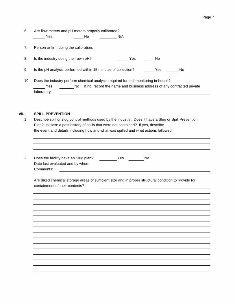
Page 7
6. Are flow meters and pH meters properly calibrated?
Yes No N/A
7. Person or firm doing the calibration:
8. Is the industry doing their own pH? Yes No
9. Is the pH analysis performed within 15 minutes of collection? Yes No
10. Does the industry perform chemical analysis required for self-monitoring in-house?
Yes No If no, record the name and business address of any contracted private
laboratory:
VII. SPILL PREVENTION
1. Describe spill or slug control methods used by the industry. Does it have a Slug or Spill Prevention
Plan? Is there a past history of spills that were not contained? If yes, describe
the event and details including how and what was spilled and what actions followed.
2. Does the facility have an Slug plan? Yes No
Date last evaluated and by whom:
Comments:
Are diked chemical storage areas of sufficient size and in proper structural condition to provide for
containment of their contents?
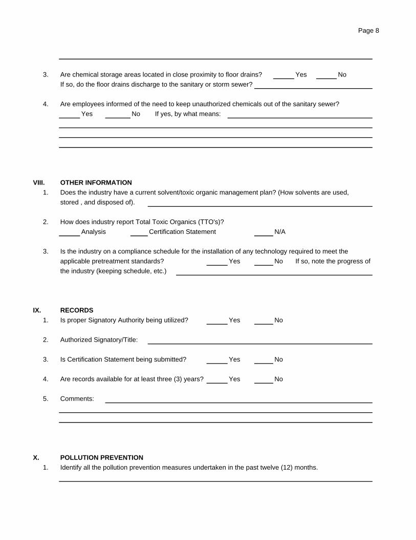
Page 8
3. Are chemical storage areas located in close proximity to floor drains? Yes No
If so, do the floor drains discharge to the sanitary or storm sewer?
4. Are employees informed of the need to keep unauthorized chemicals out of the sanitary sewer?
Yes No If yes, by what means:
VIII. OTHER INFORMATION
1. Does the industry have a current solvent/toxic organic management plan? (How solvents are used,
stored , and disposed of).
2. How does industry report Total Toxic Organics (TTO's)?
Analysis Certification Statement N/A
3. Is the industry on a compliance schedule for the installation of any technology required to meet the
applicable pretreatment standards? Yes No If so, note the progress of
the industry (keeping schedule, etc.)
IX. RECORDS
1. Is proper Signatory Authority being utilized? Yes No
2. Authorized Signatory/Title:
3. Is Certification Statement being submitted? Yes No
4. Are records available for at least three (3) years? Yes No
5. Comments:
X. POLLUTION PREVENTION
1. Identify all the pollution prevention measures undertaken in the past twelve (12) months.
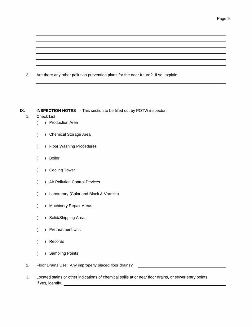
Page 9
2. Are there any other pollution prevention plans for the near future? If so, explain.
IX. INSPECTION NOTES - This section to be filled out by POTW inspector.
1. Check List
( ) Production Area
( ) Chemical Storage Area
( ) Floor Washing Procedures
( ) Boiler
( ) Cooling Tower
( ) Air Pollution Control Devices
( ) Laboratory (Color and Black & Varnish)
( ) Machinery Repair Areas
( ) Solid/Shipping Areas
( ) Pretreatment Unit
( ) Records
( ) Sampling Points
2. Floor Drains Use: Any improperly placed floor drains?
3. Located stains or other indications of chemical spills at or near floor drains, or sewer entry points.
If yes, identify.
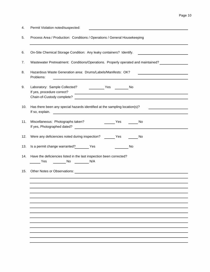
Page 10
4. Permit Violation noted/suspected:
5. Process Area / Production: Conditions / Operations / General Housekeeping
6. On-Site Chemical Storage Condition: Any leaky containers? Identify.
7. Wastewater Pretreatment: Conditions/Operations. Properly operated and maintained?
8. Hazardous Waste Generation area: Drums/Labels/Manifests: OK?
Problems:
9. Laboratory: Sample Collected? Yes No
If yes, procedure correct?
Chain-of-Custody complete?
10. Has there been any special hazards identified at the sampling location(s)?
If so, explain.
11. Miscellaneous: Photographs taken? Yes No
If yes, Photographed dated?
12. Were any deficiencies noted during inspection? Yes No
13. Is a permit change warranted? Yes No
14. Have the deficiencies listed in the last inspection been corrected?
Yes No N/A
15. Other Notes or Observations:
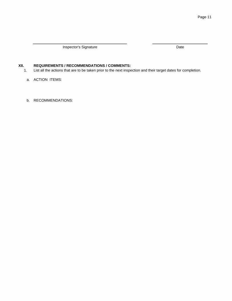
Page 11
Inspector's Signature Date
XII. REQUIREMENTS / RECOMMENDATIONS / COMMENTS:1. List all the actions that are to be taken prior to the next inspection and their target dates for completion.
a. ACTION ITEMS:
b. RECOMMENDATIONS:

Appendix P
Field Sampling Form
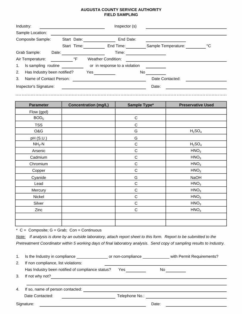
AUGUSTA COUNTY SERVICE AUTHORITYFIELD SAMPLING
Industry: Inspector (s)
Sample Location:
Composite Sample: Start Date: End Date:
Start Time: End Time: Sample Temperature: °C
Grab Sample: Date: Time:
Air Temperature: °F Weather Condition:
1. Is sampling routine or in response to a violation
2. Has Industry been notified? Yes No
3. Name of Contact Person: Date Contacted:
Inspector's Signature: Date:
Parameter Concentration (mg/L) Sample Type* Preservative Used
Flow (gpd)
BOD5 C
TSS C
O&G G H2SO4
pH (S.U.) G
NH3-N C H2SO4
Arsenic C HNO3
Cadmium C HNO3
Chromium C HNO3
Copper C HNO3
Cyanide G NaOH
Lead C HNO3
Mercury C HNO3
Nickel C HNO3
Silver C HNO3
Zinc C HNO3
* C = Composite; G = Grab; Con = Continuous
Note: If analysis is done by an outside laboratory, attach report sheet to this form. Report to be submitted to the
Pretreatment Coordinator within 5 working days of final laboratory analysis. Send copy of sampling results to Industry.
1. Is the Industry in compliance ______________ or non-compliance ____________ with Permit Requirements?
2. If non compliance, list violations:
Has Industry been notified of compliance status? Yes No
3. If not why not?
4. If so, name of person contacted:
Date Contacted: Telephone No.:
Signature: Date:

Appendix Q
Chain of Custody Document
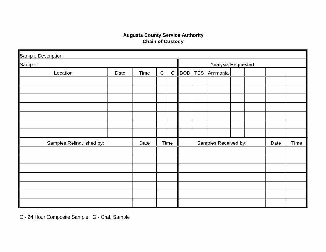
Sample Description:
Sampler:
Date Time C G BOD TSS Ammonia
Date Date Time
C - 24 Hour Composite Sample; G - Grab Sample
Augusta County Service AuthorityChain of Custody
Analysis Requested
Time Samples Received by:Samples Relinquished by:
Location

Appendix R
“New Source” Definition
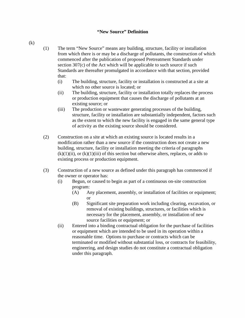
“New Source” Definition
(k) (1) The term “New Source” means any building, structure, facility or installation
from which there is or may be a discharge of pollutants, the construction of which commenced after the publication of proposed Pretreatment Standards under section 307(c) of the Act which will be applicable to such source if such Standards are thereafter promulgated in accordance with that section, provided that: (i) The building, structure, facility or installation is constructed at a site at
which no other source is located; or (ii) The building, structure, facility or installation totally replaces the process
or production equipment that causes the discharge of pollutants at an existing source; or
(iii) The production or wastewater generating processes of the building, structure, facility or installation are substantially independent, factors such as the extent to which the new facility is engaged in the same general type of activity as the existing source should be considered.
(2) Construction on a site at which an existing source is located results in a
modification rather than a new source if the construction does not create a new building, structure, facility or installation meeting the criteria of paragraphs (k)(1)(ii), or (k)(1)(iii) of this section but otherwise alters, replaces, or adds to existing process or production equipment.
(3) Construction of a new source as defined under this paragraph has commenced if
the owner or operator has: (i) Begun, or caused to begin as part of a continuous on-site construction
program: (A) Any placement, assembly, or installation of facilities or equipment;
or (B) Significant site preparation work including clearing, excavation, or
removal of existing buildings, structures, or facilities which is necessary for the placement, assembly, or installation of new source facilities or equipment; or
(ii) Entered into a binding contractual obligation for the purchase of facilities or equipment which are intended to be used in its operation within a reasonable time. Options to purchase or contracts which can be terminated or modified without substantial loss, or contracts for feasibility, engineering, and design studies do not constitute a contractual obligation under this paragraph.