DESIGN AND CONSTRUCTION STANDARDS CHAPTER 9 UTILITIES ... · effective: november 16, 2000 design...
61
Effective: November 16, 2000 DESIGN AND CONSTRUCTION STANDARDS 9-1 CITY OF BOULDER DESIGN AND CONSTRUCTION STANDARDS CHAPTER 9 UTILITIES STANDARDS TABLE OF CONTENTS Section Page 9.01 GENERAL ......................................................................................................................................................................... 4 (A) INTENT ................................................................................................................................................................................ 4 (B) SCOPE.................................................................................................................................................................................. 4 (C) REFERENCE STANDARDS ................................................................................................................................................... 4 (D) CITY APPROVAL REQUIRED............................................................................................................................................... 4 9.02 EXCAVATION AND TRENCHING .............................................................................................................................. 4 (A) G ENERAL ............................................................................................................................................................................. 4 (B) MATERIALS ........................................................................................................................................................................ 5 (C) E XECUTION ......................................................................................................................................................................... 7 9.03 DUCTILE IRON PIPE (DIP) .........................................................................................................................................13 (A) G ENERAL ........................................................................................................................................................................... 13 (B) MATERIALS ...................................................................................................................................................................... 13 (C) THRUST RESTRAINT ........................................................................................................................................................ 14 (D) CONNECTIONS TO THE E XISTING SYSTEM...................................................................................................................... 15 (E) E XECUTION ....................................................................................................................................................................... 15 9.04 POLYVINYL CHLORIDE (PVC) PRESSURE PIPE...............................................................................................18 (A) G ENERAL ........................................................................................................................................................................... 18 (B) MATERIALS ...................................................................................................................................................................... 18 (C) THRUST RESTRAINT ........................................................................................................................................................ 19 (D) CONNECTIONS TO THE E XISTING SYSTEM...................................................................................................................... 20 (E) E XECUTION ....................................................................................................................................................................... 20 9.05 WATER SERVICES ......................................................................................................................................................23 (A) G ENERAL ........................................................................................................................................................................... 23 (B) MATERIALS ...................................................................................................................................................................... 23 (C) E XECUTION ....................................................................................................................................................................... 24 9.06 GATE VALVES ..............................................................................................................................................................24 (A) G ENERAL ........................................................................................................................................................................... 24 (B) MATERIALS ...................................................................................................................................................................... 25 (C) E XECUTION ....................................................................................................................................................................... 26 9.07 BUTTERFLY VALVES .................................................................................................................................................26 (A) G ENERAL ........................................................................................................................................................................... 26 (B) MATERIALS ...................................................................................................................................................................... 26 (C) E XECUTION ....................................................................................................................................................................... 27 9.08 TAPPING SLEEVES AND VALVES ..........................................................................................................................27
Transcript of DESIGN AND CONSTRUCTION STANDARDS CHAPTER 9 UTILITIES ... · effective: november 16, 2000 design...

Effective: November 16, 2000 DESIGN AND CONSTRUCTION STANDARDS 9-1
CITY OF BOULDER
DESIGN AND CONSTRUCTION STANDARDS
CHAPTER 9UTILITIES STANDARDS
TABLE OF CONTENTS
Section Page
9.01 GENERAL.........................................................................................................................................................................4
(A) INTENT ................................................................................................................................................................................ 4(B) SCOPE.................................................................................................................................................................................. 4(C) REFERENCE STANDARDS ................................................................................................................................................... 4(D) CITY APPROVAL REQUIRED............................................................................................................................................... 4
9.02 EXCAVATION AND TRENCHING..............................................................................................................................4
(A) GENERAL............................................................................................................................................................................. 4(B) MATERIALS ........................................................................................................................................................................ 5(C) EXECUTION ......................................................................................................................................................................... 7
9.03 DUCTILE IRON PIPE (DIP).........................................................................................................................................13
(A) GENERAL........................................................................................................................................................................... 13(B) MATERIALS ...................................................................................................................................................................... 13(C) THRUST RESTRAINT ........................................................................................................................................................ 14(D) CONNECTIONS TO THE EXISTING SYSTEM...................................................................................................................... 15(E) EXECUTION ....................................................................................................................................................................... 15
9.04 POLYVINYL CHLORIDE (PVC) PRESSURE PIPE...............................................................................................18
(A) GENERAL........................................................................................................................................................................... 18(B) MATERIALS ...................................................................................................................................................................... 18(C) THRUST RESTRAINT ........................................................................................................................................................ 19(D) CONNECTIONS TO THE EXISTING SYSTEM...................................................................................................................... 20(E) EXECUTION ....................................................................................................................................................................... 20
9.05 WATER SERVICES ......................................................................................................................................................23
(A) GENERAL........................................................................................................................................................................... 23(B) MATERIALS ...................................................................................................................................................................... 23(C) EXECUTION ....................................................................................................................................................................... 24
9.06 GATE VALVES ..............................................................................................................................................................24
(A) GENERAL........................................................................................................................................................................... 24(B) MATERIALS ...................................................................................................................................................................... 25(C) EXECUTION ....................................................................................................................................................................... 26
9.07 BUTTERFLY VALVES .................................................................................................................................................26
(A) GENERAL........................................................................................................................................................................... 26(B) MATERIALS ...................................................................................................................................................................... 26(C) EXECUTION ....................................................................................................................................................................... 27
9.08 TAPPING SLEEVES AND VALVES..........................................................................................................................27

9-2 DESIGN AND CONSTRUCTION STANDARDS Effective: November 16, 2000
(A) GENERAL........................................................................................................................................................................... 27(B) MATERIALS ...................................................................................................................................................................... 28(C) EXECUTION ....................................................................................................................................................................... 29
9.09 FIRE HYDRANTS..........................................................................................................................................................29
(A) GENERAL........................................................................................................................................................................... 29(B) MATERIALS ...................................................................................................................................................................... 29(C) EXECUTION ....................................................................................................................................................................... 30
9.10 COMBINATION AIR VALVE.....................................................................................................................................30
(A) GENERAL........................................................................................................................................................................... 30(B) MATERIALS ...................................................................................................................................................................... 30(C) EXECUTION ....................................................................................................................................................................... 31
9.11 DISINFECTING WATERLINES .................................................................................................................................31
(A) SCOPE................................................................................................................................................................................ 31(B) MATERIALS ...................................................................................................................................................................... 31(C) EXECUTION ....................................................................................................................................................................... 31
9.12 TESTING OF WATER PIPES .....................................................................................................................................32
(A) GENERAL........................................................................................................................................................................... 32(B) MATERIALS ...................................................................................................................................................................... 33(C) EXECUTION ....................................................................................................................................................................... 33
9.13 POLYVINYL CHLORIDE (PVC) NON-PRESSURE PIPE.....................................................................................34
(A) GENERAL........................................................................................................................................................................... 34(B) MATERIALS ...................................................................................................................................................................... 34(C) EXECUTION ....................................................................................................................................................................... 35
9.14 REINFORCED CONCRETE PIPE..............................................................................................................................38
(A) GENERAL........................................................................................................................................................................... 38(B) MATERIALS ...................................................................................................................................................................... 38(C) EXECUTION ....................................................................................................................................................................... 39
9.15 MANHOLES AND INLETS .........................................................................................................................................41
(A) GENERAL........................................................................................................................................................................... 41(B) MATERIALS ...................................................................................................................................................................... 41(C) EXECUTION ....................................................................................................................................................................... 43
9.16 TESTING OF GRAVITY SEWER PIPELINES AND MANHOLES ......................................................................44
(A) GENERAL........................................................................................................................................................................... 44(B) MATERIALS ...................................................................................................................................................................... 44(C) EXECUTION ....................................................................................................................................................................... 44(D) SANITARY SEWER MANHOLES ........................................................................................................................................ 46
9.17 CORRUGATED METAL PIPE....................................................................................................................................47
(A) GENERAL........................................................................................................................................................................... 47(B) MATERIALS ...................................................................................................................................................................... 47(C) EXECUTION ....................................................................................................................................................................... 48
9.18 CURED-IN-PLACE PIPE (CIPP..................................................................................................................................49
(A) GENERAL........................................................................................................................................................................... 49(B) MATERIALS ...................................................................................................................................................................... 49(C) EXECUTION ....................................................................................................................................................................... 50

Effective: November 16, 2000 DESIGN AND CONSTRUCTION STANDARDS 9-3
9.19 TELECOMMUNICATION OR CABLE SYSTEM STANDARDS.........................................................................53
(A) GENERAL........................................................................................................................................................................... 53(B) UNDERGROUND FACILITIES ............................................................................................................................................. 54(C) ABOVEGROUND FACILITIES ............................................................................................................................................. 55
9.20 ELECTRIC POWER FACILITY STANDARDS.......................................................................................................56
(A) GENERAL........................................................................................................................................................................... 57(B) UNDERGROUND FACILITIES ............................................................................................................................................. 57(C) ABOVEGROUND FACILITIES ............................................................................................................................................. 58
9.21 GAS DISTRIBUTION FACILITY STANDARDS....................................................................................................59
(A) GENERAL........................................................................................................................................................................... 59(B) UNDERGROUND FACILITIES ............................................................................................................................................. 59(C) TESTING REQUIREMENTS................................................................................................................................................. 61(D) ABOVEGROUND FACILITIES… ……………………………………………………………………………….61
LIST OF TABLES
Number Page
Table 9-1: Granular Bedding Material for Ductile Iron Pipe and PVC Pressure Pipe ..................................................... 5Table 9-2: Granular Bedding Material for PVC and HDPE Sewer Pipe............................................................................. 6Table 9-3: Granular Bedding Material for RCP Sewer Pipe ................................................................................................ 6Table 9-4: Flowable Fill Requirements .................................................................................................................................. 6Table 9-5: Tube Size and Sheet Width for Pipe Diameter................................................................................................ 14Table 9-6: Ductile-Iron Pipe Deflection............................................................................................................................... 16Table 9-7: Pipe Laying........................................................................................................................................................... 20Table 9-8: Curvilinear Sewer Pipe Laying........................................................................................................................... 36Table 9-9: Required Manhole Diameters ............................................................................................................................ 41Table 9-10: Specifications for Air Testing of Sanitary Sewer Pipes ................................................................................. 46Table 9-11: Corrugated Base Metal Specifications............................................................................................................. 48

9-4 DESIGN AND CONSTRUCTION STANDARDS Effective: November 16, 2000
9.01 General
(A) Intent
The Utilities Standards are intended to complement the design standards specified in Chapter 4,“General Utilities Design,” Chapter 5, “Water Design,” Chapter 6, “Wastewater Design,” Chapter 7,“Storm Water Design,” and Chapter 11, “Technical Drawings,” of these Standards, and provideminimum standards for the construction of public utilities improvements in public rights-of-way andpublic easements.
(B) Scope
These Standards apply to all city-operated public utility improvements within the City of Boulderservice area. This chapter describes the construction of public utilities and other work within thepublic right-of-way including, but not limited to, work activities involved, materials used, installationmethods, and required testing. The utilities construction requirements of this chapter are in addition tothose set forth in Chapter 4, “General Utilities Design,” Chapter 5, “Water Design,” Chapter 6,“Wastewater Design,” Chapter 7, “Storm Water Design,” and Chapter 11, “Technical Drawings,” ofthese Standards and the B.R.C. 1981.
(C) Reference Standards
Where not specified in these Standards or the B.R.C. 1981, in order to protect the public health,safety, and welfare, the Director of Public Works will specify the standards to be applied to thedesign and construction of streetscapes and the planting of trees, and may refer to one or more of thereferences listed in the References Section of these Standards.
(D) City Approval Required
All work associated with the construction of public utilities within or upon any City of Boulder publicright-of-way or public easement is subject to City of Boulder approval or permit issuance as set forthin Chapter 8-5, “Work in the Public Right-Of-Way and Public Easements.”
9.02 Excavation and Trenching
(A) General
(1) Scope: This section describes excavation and trenching, which includes the following:
(a) Necessary clearing, grubbing, and preparation of the site;
(b) Removal and disposal of debris; excavation and trenching as required;
(c) The handling, storage, transportation, and disposal of all excavated material;
(d) Necessary sheeting, shoring, and protection work;
(e) Preparation of subgrades;
(f) Pumping and dewatering as necessary or required;
(g) Protection of adjacent property
(h) Backfilling;

Effective: November 16, 2000 DESIGN AND CONSTRUCTION STANDARDS 9-5
(i) Pipe embedment;
(j) Placement of fills;
(k) Surfacing and grading; and
(l) Other relevant work.
(2) Quality Assurance: All tests required for the preliminary review of materials shall be madeby an acceptable independent testing laboratory; at the expense of the contractor. Two initialgradation tests shall be made for each type of pipe bedding, fill, or backfill material, and oneadditional gradation test shall be made for each additional 500 tons of each material. Thecontractor shall pay for all in-place field density tests, Proctor moisture-density tests, andrelative density tests on the materials as required.
(B) Materials
(1) General: All bedding and backfill material shall be free of frozen material, organic material,and debris.
(2) Pipe Bedding: Bedding materials shall conform to the following requirements.
(a) Bedding Materials: Bedding materials shall not contain cinders or other material thatmay cause pipe corrosion.
(b) Concrete Arch Encasement: A concrete arch encasement is not required unlessimproper trenching or unexpected trench conditions require its use, as determinedby the Director.
(c) Granular Bedding Material for Ductile Iron Pipe and PVC Pressure Pipe: Thismaterial shall be washed chips, 3/8 inch in nominal size. Table 9-1, “ GranularBedding Material for Ductile Iron Pipe and PVC Pressure Pipe,” outlines thegradation requirements:
Table 9-1: Granular Bedding Material for Ductile Iron Pipe and PVC Pressure Pipe
Sieve Size or Designation Percent Passing by Weight
1/2" 100%
3/8" 85-100%
No. 4 10-30%
No. 8 0-10%
NOTE: The Director may approve the use of squeegee sand conforming to the gradation in Table 9-3, “GranularBedding for RCP Sewer Pipe,” of these Standards.
(d) Compaction: All granular bedding material shall be compacted by vibrating or slicingwith a shovel and placed in layers no more than 6 inches thick.
(e) Granular Bedding Material for PVC and HDPE Sewer Pipe: This material shall beimported, crushed, angular quarry rock. Table 9-2, “Granular Bedding Material forPVC and HDPE Sewer Pipe,” outlines the gradation requirements (ASTM D448, No.67):

9-6 DESIGN AND CONSTRUCTION STANDARDS Effective: November 16, 2000
Table 9-2: Granular Bedding Material for PVC and HDPE Sewer Pipe
Sieve Size or Designation Total Passing (Percent by Weight)
3/4" 100%
3/8" 20-55%
No. 8 0-10%
No. 200 0-5%
(f) Granular Bedding Material for RCP Sewer Pipe: This material shall be squeegeesand. Table 9-3, “Granular Bedding Material for RCP Sewer Pipe,” outlines thegradation requirements:
Table 9-3: Granular Bedding Material for RCP Sewer Pipe
Sieve Size or Designation Total Passing (Percent by Weight)
3/8" 100%
No. 200 0-5%
(3) Stabilization Material: Stabilization material shall be placed on suitably prepared subgradesand compacted by vibration. Stabilization material shall be crushed rock or gravel; free fromdust, clay, or trash; and graded 1 ½ inch to No. 4 as defined in ASTM C33, and shall becompacted to not less than 70 percent relative density as determined by ASTM D4253 andD4254.
(4) Trench Backfill: Trench backfill is material placed above the pipe bedding and shall beflowable fill or an approved equivalent as set forth in Section 8-5-12, “Standards for Repairsand Restoration of Pavement or Sidewalks,” B.R.C. 1981.
(5) Groundwater Barrier Material: Groundwater barrier material shall be flowable fill or meetAASHTO soil classification SC or CL, free from stones, organic material or debris.
(6) Flowable Fill: Flowable fill, meeting the standards outlined in Table 9-4, “Flowable FillRequirements,” shall be used for trench backfill or for groundwater barriers.
Table 9-4: Flowable Fill Requirements
Ingredients Lbs./C.Y. Kg/m3
Cement 50 30
Coarse Aggregate (AASHTO No. 57 or 67) 1,700 1,009
Fine Aggregate (AASHTO M 6) 1,845 1,095
Water (39 gallons) (147L) 325 (or as needed) 193 (or as needed)
(a) Enough water shall be used so that the flowable fill flows into place properly withoutexcessive segregation. Approximately 39 gallons of water per cubic yard (193 litersper cubic meter) of flowable fill is normally needed. Additional water shall not beadded to the mixture at the project site.
(b) The contractor may use aggregate that does not meet the specifications in Table 9-4,“Flowable Fill Requirements,” if the cement is increased to 100 pounds per cubic

Effective: November 16, 2000 DESIGN AND CONSTRUCTION STANDARDS 9-7
yard (60 kilograms per cubic meter) and the aggregate conforms to followinggradation:
Sieve Size or Designation Percent Passing
1" (25.0 mm) 100%
No. 200 0-10%
(c) The contractor may make the following substitutions in the flowable fill mix:
(i) Thirty pounds per cubic yard (18 kilograms per cubic meter) of cement and30 pounds per cubic yard (18 kilograms per cubic meter) of fly ash for 50pounds per cubic yard (30 kilograms per cubic meter) of cement, or
(ii) Sixty pounds per cubic yard (36 kilograms per cubic meter) of cement and60 pounds per cubic yard (36 kilograms per cubic meter) of fly ash for 100pounds per cubic yard (60 kilograms per cubic meter) of cement.
(d) The City reserves the right to review the use of recycled broken glass (glass cullet)as part or all of the aggregate.
(e) Compaction of flowable fill shall not be required
(f) The maximum layer thickness for flowable fill shall be 3-feet. Additional layers shallnot be placed until the flowable fill has lost sufficient moisture to be walked onwithout indenting more than 2-inches. Any damage resulting form placing flowablefill in layers that are too thick or from not allowing sufficient time betweenplacement of layers shall be repaired at the Contractor’s expense.
(7) Rock Backfill Material: Rock backfill material shall be an imported graded material thatmeets either the 57/67 size requirements of ASTM C33 or the requirements for stabilizationmaterial specified in Subsection 9.02(B)(3).
(C) Execution
(1) Site Preparation
(a) All sites to be occupied by permanent construction shall be cleared of all logs, trees,roots, brush, tree trimmings, and other objectionable materials and debris. Allstumps shall be grubbed. All waste materials shall be removed from the site andproperly disposed.
(b) In natural areas where excavation will occur all topsoil shall be stripped or, in theabsence of topsoil, the top 6 inches of surface material shall be stripped and storedseparately from other excavated materials.
(c) For concrete walks, roadways, parking areas, and road crossings existing pavementshall be cut full depth to a true line before excavation. For Portland Cementpavements, cuts shall be made at existing joints.
(2) Classification of Excavated Materials: Excavated materials shall not be classified. Excavation and trenching work shall include the removal and subsequent handling of allmaterials excavated or otherwise removed in performance of the work, regardless of thetype, character, composition, or condition thereof.
(3) Unauthorized Excavation: Undermining or tunneling under walls, footings, slabs on grade,foundations, sidewalks, concrete or bituminous asphalt pavements, or any other surface or

9-8 DESIGN AND CONSTRUCTION STANDARDS Effective: November 16, 2000
subsurface facilities or structures shall not be permitted unless authorized by the Director. Ifunauthorized tunneling or undermining occurs, the contractor shall pay for all repairs andrestorations the Director deems necessary. The repairs and restorations may includeremoving and replacing part or all of the affected facility or structure.
(4) Stabilization of Subgrades
(a) Subgrades for concrete structures and trench bottoms shall be firm, dense,thoroughly compacted and consolidated, and free from mud and muck.
(b) Subgrades for concrete structures or trench bottoms that are otherwise solid, butbecome mucky on top due to construction operations, shall be reinforced withcrushed rock or gravel meeting the requirements for stabilization material, describedin Subsection 9.02(B)(3) of these Standards and approved by the Director.
(c) Stabilization material shall be spread and compacted to a depth of not more than 4inches. However, if the required depth exceeds 4 inches, the subgrade for concretestructures or trench bottom shall be re-excavated and all mud and muck removedand replaced with stabilization material, as required by Section 9.02(B)(3) of theseStandards and approved by the Director.
(d) This material shall be placed, and compacted, as prescribed in these Standards. Thefinished elevation of stabilized subgrades shall not be above subgrade elevationsindicated on the drawings.
(5) Blasting: Blasting or other use of explosives for excavation will not be permitted.
(6) Shoring
(a) All excavations shall be properly shored and braced to meet federal, state and locallaws governing safe working conditions. The shoring shall be arranged so that nostress is placed on any portion of the completed work until the general constructionthereof has proceeded far enough to provide ample strength.
(b) Shoring shall be removed as the work progresses. Trench sheeting shall not bepulled before backfilling unless the pipe strength is sufficient to carry trench loadsbased on trench width to the back of sheeting, nor shall sheeting be pulled afterbackfilling.
(c) Where trench sheeting is left in place, such sheeting shall not be braced against thepipe, but shall be supported in a manner that will preclude concentrated loads orhorizontal thrusts on the pipe. Cross braces installed above the pipe to supportsheeting may be removed after pipe embedment has been completed.
(d) The contractor shall pay to repair any damage to pipes or structures resulting frommissing, failed or improper shoring, sheeting, or bracing or any negligence on thepart of the contractor.
(7) Water Control and Dewatering
(a) Dewatering equipment shall be provided to remove and dispose of all surface waterand groundwater entering excavations, trenches, or other parts of the work. Eachexcavation shall be kept dry during subgrade preparation and until the structure to bebuilt or the pipe to be installed is completed to the extent that no damage fromhydrostatic pressure, flotation, or other cause will result.
(b) All excavations for concrete structures or trenches that extend down to or below thegroundwater table shall be dewatered by lowering and keeping the groundwater level

Effective: November 16, 2000 DESIGN AND CONSTRUCTION STANDARDS 9-9
12 inches or more below the bottom of the excavation.
(c) Surface water shall be diverted or otherwise prevented from entering the excavatedareas or trenches to the greatest extent practicable without causing damage toadjacent property.
(d) The contractor shall be responsible for the condition of any pipe or conduit used fordrainage purposes. All such pipe or conduit shall be left clean and free of sediment.
(8) Trench Excavation: Trenches shall be excavated so that pipes can be laid according to theprofiles, grades, elevations, and minimum cover shown on the drawings or specified in theseStandards. Trench subgrades shall be clean and free of loose material of any kind.
(a) Excavation in Streets and Other Paved Surfaces: Excavations in streets with asphaltpaving must be confined to the minimum width required to maintain a safe trenchcondition. The contractor shall pay for replacing any pavement damage resultingfrom their construction work. The Director will determine the limits of the damagedpavement needing replacement.
(b) Minimum Cover: Where pipe grades or elevations are not definitely fixed by theapproved plans, trenches shall be excavated to a depth sufficient to provide aminimum depth of backfill cover over the top of the pipe as follows:
(i) Water lines require at least 4.5 feet of cover;
(ii) Sanitary sewers require at least 3 feet of cover; and
(iii) Storm sewers require at least 1.5 feet of cover.
(c) Trench Widths
(i) Trench widths shall be as shown below where the maximum trench widthis measured at the top of the pipe barrel.
Pipe DiameterInches
Maximum TrenchInches
Pipe DiameterInches
Maximum TrenchInches
4 24 24 48
6 26 27 52
8 28 30 56
10 30 33 60
12 34 36 68
14 36 39 72
15 37 42 76
16 38 48 82
18 40 54 90
20 42 72 110
21 44
(ii) If the stated maximum trench widths are exceeded, and if the Directordetermines that the combined dead- and live-loads will exceed the design
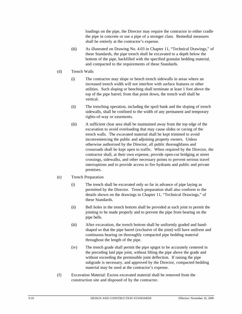
9-10 DESIGN AND CONSTRUCTION STANDARDS Effective: November 16, 2000
loadings on the pipe, the Director may require the contractor to either cradlethe pipe in concrete or use a pipe of a stronger class. Remedial measuresshall be entirely at the contractor’s expense.
(iii) As illustrated on Drawing No. 4.03 in Chapter 11, “Technical Drawings,” ofthese Standards, the pipe trench shall be excavated to a depth below thebottom of the pipe, backfilled with the specified granular bedding material,and compacted to the requirements of these Standards.
(d) Trench Walls
(i) The contractor may slope or bench trench sidewalls in areas where anincreased trench width will not interfere with surface features or otherutilities. Such sloping or benching shall terminate at least 1 foot above thetop of the pipe barrel; from that point down, the trench wall shall bevertical.
(ii) The trenching operation, including the spoil bank and the sloping of trenchsidewalls, shall be confined to the width of any permanent and temporaryrights-of-way or easements.
(iii) A sufficient clear area shall be maintained away from the top edge of theexcavation to avoid overloading that may cause slides or caving of thetrench walls. The excavated material shall be kept trimmed to avoidinconveniencing the public and adjoining property owners. Unlessotherwise authorized by the Director, all public thoroughfares andcrossroads shall be kept open to traffic. When required by the Director, thecontractor shall, at their own expense, provide open-cut bridging at streetcrossings, sidewalks, and other necessary points to prevent serious travelinterruptions and to provide access to fire hydrants and public and privatepremises.
(e) Trench Preparation
(i) The trench shall be excavated only so far in advance of pipe laying aspermitted by the Director. Trench preparation shall also conform to thedetails shown on the drawings in Chapter 11, “Technical Drawings,” ofthese Standards.
(ii) Bell holes in the trench bottom shall be provided at each joint to permit thejointing to be made properly and to prevent the pipe from bearing on thepipe bells.
(iii) After excavation, the trench bottom shall be uniformly graded and hand-shaped so that the pipe barrel (exclusive of the joint) will have uniform andcontinuous bearing on thoroughly compacted pipe bedding materialthroughout the length of the pipe.
(iv) The trench grade shall permit the pipe spigot to be accurately centered inthe preceding laid pipe joint, without lifting the pipe above the grade andwithout exceeding the permissible joint deflection. If raising the pipesubgrade is necessary, and approved by the Director, compacted beddingmaterial may be used at the contractor’s expense.
(f) Excavation Material: Excess excavated material shall be removed from theconstruction site and disposed of by the contractor.
Effective: November 16, 2000 DESIGN AND CONSTRUCTION STANDARDS 9-11
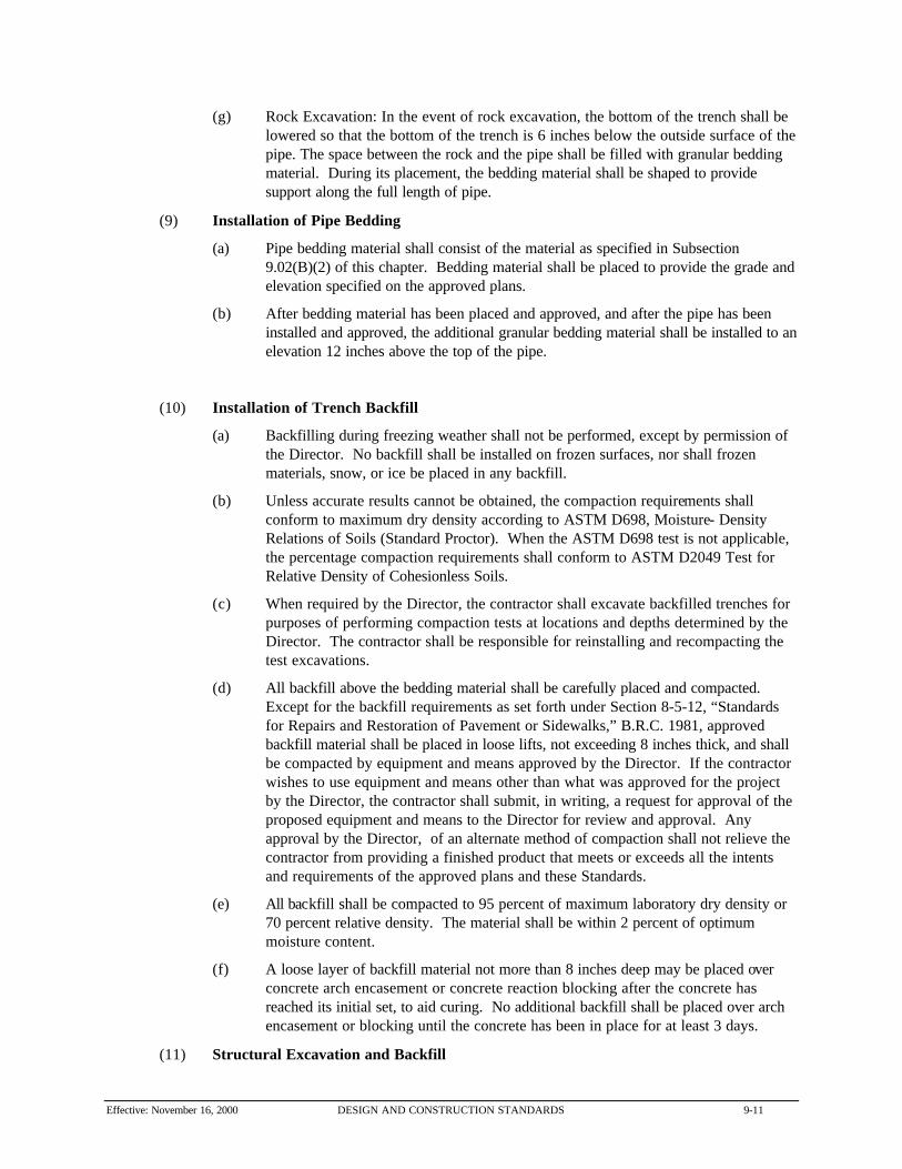
(g) Rock Excavation: In the event of rock excavation, the bottom of the trench shall belowered so that the bottom of the trench is 6 inches below the outside surface of thepipe. The space between the rock and the pipe shall be filled with granular beddingmaterial. During its placement, the bedding material shall be shaped to providesupport along the full length of pipe.
(9) Installation of Pipe Bedding
(a) Pipe bedding material shall consist of the material as specified in Subsection9.02(B)(2) of this chapter. Bedding material shall be placed to provide the grade andelevation specified on the approved plans.
(b) After bedding material has been placed and approved, and after the pipe has beeninstalled and approved, the additional granular bedding material shall be installed to anelevation 12 inches above the top of the pipe.
(10) Installation of Trench Backfill
(a) Backfilling during freezing weather shall not be performed, except by permission ofthe Director. No backfill shall be installed on frozen surfaces, nor shall frozenmaterials, snow, or ice be placed in any backfill.
(b) Unless accurate results cannot be obtained, the compaction requirements shallconform to maximum dry density according to ASTM D698, Moisture- DensityRelations of Soils (Standard Proctor). When the ASTM D698 test is not applicable,the percentage compaction requirements shall conform to ASTM D2049 Test forRelative Density of Cohesionless Soils.
(c) When required by the Director, the contractor shall excavate backfilled trenches forpurposes of performing compaction tests at locations and depths determined by theDirector. The contractor shall be responsible for reinstalling and recompacting thetest excavations.
(d) All backfill above the bedding material shall be carefully placed and compacted. Except for the backfill requirements as set forth under Section 8-5-12, “Standardsfor Repairs and Restoration of Pavement or Sidewalks,” B.R.C. 1981, approvedbackfill material shall be placed in loose lifts, not exceeding 8 inches thick, and shallbe compacted by equipment and means approved by the Director. If the contractorwishes to use equipment and means other than what was approved for the projectby the Director, the contractor shall submit, in writing, a request for approval of theproposed equipment and means to the Director for review and approval. Anyapproval by the Director, of an alternate method of compaction shall not relieve thecontractor from providing a finished product that meets or exceeds all the intentsand requirements of the approved plans and these Standards.
(e) All backfill shall be compacted to 95 percent of maximum laboratory dry density or70 percent relative density. The material shall be within 2 percent of optimummoisture content.
(f) A loose layer of backfill material not more than 8 inches deep may be placed overconcrete arch encasement or concrete reaction blocking after the concrete hasreached its initial set, to aid curing. No additional backfill shall be placed over archencasement or blocking until the concrete has been in place for at least 3 days.
(11) Structural Excavation and Backfill

9-12 DESIGN AND CONSTRUCTION STANDARDS Effective: November 16, 2000
(a) All structural excavations shall provide adequate working space and clearances forthe work to be performed therein and for installation and removal of concrete forms. In no case shall excavation faces be undercut for extended footings.
(b) Backfilling during freezing weather shall not be performed, except by permission ofthe Director. No backfill shall be installed on frozen surfaces, nor shall frozenmaterials, snow, or ice be placed in any backfill.
(c) The quality and moisture content of materials for backfill around and outside ofstructures shall conform to the requirements for materials used for earthfills andembankments. Backfill materials shall be placed in loose lifts, not to exceed 8 inchesin thickness, and shall be compacted to at least 95 percent of maximum dry densityat optimum moisture content as determined by ASTM D698. Compaction ofstructure backfill by rolling will be permitted, provided the desired compaction isobtained and damage to the structure is prevented. Compaction of structure backfillby inundation with water will not be permitted.
(d) No backfill shall be deposited or compacted in water.
(e) Particular care shall be taken to compact structure backfill that will be beneath pipes,drives, roads, parking areas, walks, curbs, gutters, or other surface construction orstructures. In addition, wherever a trench is to pass through structure backfill, thestructure backfill shall be placed and compacted to an elevation not less that 12inches above the top of pipe elevation before the trench is excavated. Compactedareas, in each case, shall be adequate to support the item to be constructed or placedthereon.
(12) Restoration
(a) Streets and Roadways: Any pavements disturbed during construction shall berepaired in accordance with the requirements as set forth in Section 8-5-12,“Standards for Repairs and Restoration of Pavement or Sidewalks,” B.R.C. 1981. Alldirt and debris, including dust shall be removed from streets and paved surfaceswithin 3 days of the restoration of streets and paved surfaces. Initial removal of dirtand debris shall be made using a vacuum sweeper, after which the paved surfacesshall be cleaned using water hoses.
(b) Fencing and Culverts: Restore all existing structures to conditions equal to orexceeding existing structures.
(c) Landscape
(i) After other outside work has been finished, and backfilling andembankments completed and settled, all areas that are to be graded shall bebrought to grade at the indicated elevations, slopes, and contours. All cuts,fills, embankments, and other areas that have been disturbed or damaged byconstruction operations shall be surfaced with topsoil to a depth of at least 4inches. Topsoil shall be of a quality at least equal to the existing topsoil inadjacent areas, free from trash, stones, and debris, and well suited tosupport plant growth.
(ii) Use of graders or other power equipment will be permitted for final gradingand dressing of slopes, provided the result is uniform and equivalent to handwork. All surfaces shall be graded to secure effective drainage. Unlessotherwise indicated, a slope of at least 1 percent shall be provided.

Effective: November 16, 2000 DESIGN AND CONSTRUCTION STANDARDS 9-13
(iii) Final grading and surfacing shall be smooth, even, and free from clods andstones larger than 1 inch in greatest dimension, weeds, brush, and otherdebris.
(iv) The top portion of backfill beneath established lawn areas shall be finishedwith at least 12 inches of topsoil corresponding to, or better than, thatunderlying adjoining lawn areas.
(v) The Director will clarify restoration of other minor items as constructionproceeds. Such items must be restored to equal or exceed existingconditions.
(13) Cleanup: Prior to final inspection and acceptance, the contractor shall remove all rubbishand excess materials and leave the area in a neat, satisfactory condition.
(14) Maintenance of Backfill: All backfill shall be maintained in a satisfactory condition and allplaces showing signs of settlement shall be filled and maintained for a period of 2 yearsfollowing the date of final acceptance of all work. When the contractor discovers or isnotified by the City that any backfill is not in compliance with City standards, the contractorshall correct such conditions. Any utilities and road surfacing damaged by such settlementshall be repaired by the contractor to the satisfaction of the City. In addition, the contractorshall be responsible for the cost of all claims for damages due to settlement of backfilledareas.
9.03 Ductile Iron Pipe (DIP)
(A) General
(1) Scope: This section describes the furnishing and installation of ductile iron pipe andappurtenances for potable water mains, water services and fire lines in the pipe diameter sizerange of 4 inches to 24 inches.
(2) Quality Assurance: Manufacturer’s certificates of compliance and installationrecommendations shall be provided to the City inspector prior to construction. Installationrecommendations shall be followed during construction.
(B) Materials
(1) Ductile Iron Pipe:
(a) Unless revised on the approved drawings the ductile-iron pipe shall conform toANSI A21.51, AWWA C151, Class 52 thickness. The interior of each length ofpipe shall have a cement-mortar lining, conforming to the requirements set forth inANSI A21.4, AWWA C104, of standard thickness. The exterior of the pipe shall becoated with standard bituminous coating approximately 1 mil thick.
(b) Unless otherwise specified the pipe joint shall be the “push-on” type, made inaccordance with ANSI A21.11, AWWA C111, and the gaskets shall be standard forburied water service and as provided by the pipe manufacturer.
(c) The fittings shall be ductile-iron or cast-iron conforming to the requirements setforth in ANSI A21.10, AWWA C110. All cast-iron fittings 12 inches and smallershall be Class 250, and fittings larger than 12 inches shall be Class 150. The interiorof the fittings shall be epoxy or cement-mortar lined, as is required for the pipe with

9-14 DESIGN AND CONSTRUCTION STANDARDS Effective: November 16, 2000
a 1 mil bituminous exterior coating. The fittings shall have mechanical joints inaccordance with ANSI A21.11, AWWA C111. The gaskets for the joints shall besuitable for potable water service.
(2) Polyethylene Encasement: The ductile-iron pipeline and fittings shall be encased inpolyethylene film in accordance with the following requirements of ANSI A21.5, AWWAC105:
(a) Polyethylene:
(i) The polyethylene film shall be manufactured of virgin polyethylene materialconforming to the requirement of ASTM D-1248. The raw materials shallbe Type 1, Class A (natural) or C (Black) Grade E-1 with flow rate of 0.4maximum of dielectric strength of 1015 ohm-cm3 minimum.
(ii) The finished polyethylene film shall have a minimum nominal thickness of0.008-inch (8 mil), and the minus tolerance on thickness shall not exceed 10percent of the nominal thickness. The film shall have a minimum tensilestrength of 1200 pounds per square inch (psi) with an elongation of 300percent minimum. The dielectric strength shall be 800-volts/mil thicknessminimum.
(b) Tube Size or Sheet Width: Table 9-5, “Tube Size and Sheet Width for PipeDiameter,” shows the tube size or sheet width for each pipe diameter.
Table 9-5: Tube Size and Sheet Width for Pipe Diameter
Nominal Pipe Diameter (Inches) Flat Tube Minimum Sheet Width (Inches)
4” 16” 32”
6” 20” 40”
8” 24” 48”
10” 27” 54”
12” 30” 60”
14” 34” 68”
16” 37” 74”
18” 41” 82”
20” 45” 90”
24” 54” 108”
(C) Thrust Restraint
Where designated by the Engineer with expertise in thrust restraint systems, or where existingconditions do not permit the use of concrete thrust blocks, individual joint restraint systems shall beprovided as follows:
(1) Alternative A: Full length tie rods between joints. “Star” systems fabricated from “Cor-Ten” steel or equal according to the requirements of ASTM A-242 with a minimum yield

Effective: November 16, 2000 DESIGN AND CONSTRUCTION STANDARDS 9-15
stress of 46,000 psi. The number and diameter of tie rods shall be as shown on the detaildrawings.
(2) Alternative B: Pacific States Lock Mechanical Joint with Tyton Joint Core or equivalent. Assembly of the Tyton Joint portion of the product shall be in accordance with AWWAC600-77. Fittings with the joint restraint feature shall be ductile iron and shall conform toANSI Standard A21.10. Push-on joints for such fittings shall be in accordance with AWWAStandard A121.11.
(3) Alternative C
(a) Follower gland type systems may be used for 12-inch diameter pipe and smaller. Pipe clamps shall be fabricated from “Cor-Ten” steel or equivalent according to therequirements of ASTM A-242 with a minimum yield stress of 46,000 psi. Thenumber and diameter of tie rods shall be as shown on the detail drawings. Thefollower gland shall be manufactured of ductile iron conforming to ASTM A536. Dimensions of the gland shall be such that it can be used with the standardizedmechanical joint bell and tee head bolts conforming to AWWA C111 and C153.
(b) The restraint mechanism shall consist of numerous individually activated grippingsurfaces to maximize restraint capability. Twist-off nuts, sized the same as tee headbolts, shall be used to insure proper actuating of restraining devices. When the nutis sheared off, a standard hex nut shall remain. The device shall have a workingpressure of at least 200-psi with a minimum safety factor of 2:1.
(c) Follower gland joint restraint devices shall be of the type listed below:
(i) “EBAA Iron, Inc.,” Megalug 1100 Series (4"-12")
(ii) “Uniflange,”1400 Series (4"-12")
(D) Connections to the Existing System
(1) System Operation: Operation of the existing system must at all times remain under thecontrol of the Director. The contractor shall operate no valves or hydrants on the systemwithout permission from the Director.
(2) Connections: All points at which the existing water systems are to be disconnected andconnected to the new mains must be shown on the approved drawings.
(3) Utility Service Interruptions: The contractor shall take all precautions necessary tominimize interruption of all utility services and will be responsible for the restoration of theaffected service. The contractor shall schedule existing valve locates with the Director atleast 3 days before scheduling a shutoff.
(4) Unless otherwise specified, at any time a customer on the existing system will be deprived ofa supply of water, the contractor shall advise such customer in writing 48 hours in advanceof when the supply will be disconnected and reestablished.
(E) Execution
(1) Installation of Ductile Iron Pipe: Except as specified herein or unless specificallyauthorized by the Director, all installation of pipe shall conform to the recommendationscontained in “A Guide for Installation of Ductile-Iron Pipe,” published by the Ductile IronPipe Research Association. The contractor shall assure that a copy is available at the jobsite.
9-16 DESIGN AND CONSTRUCTION STANDARDS Effective: November 16, 2000
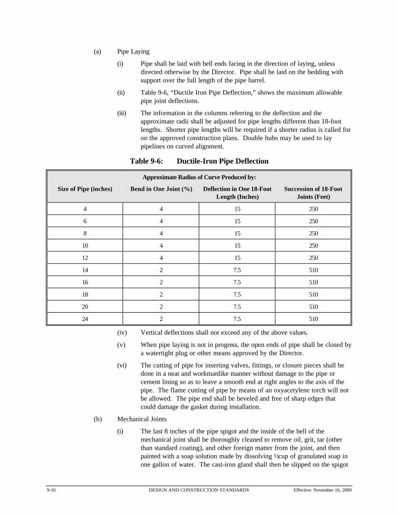
(a) Pipe Laying
(i) Pipe shall be laid with bell ends facing in the direction of laying, unlessdirected otherwise by the Director. Pipe shall be laid on the bedding withsupport over the full length of the pipe barrel.
(ii) Table 9-6, “Ductile Iron Pipe Deflection,” shows the maximum allowablepipe joint deflections.
(iii) The information in the columns referring to the deflection and theapproximate radii shall be adjusted for pipe lengths different than 18-footlengths. Shorter pipe lengths will be required if a shorter radius is called foron the approved construction plans. Double hubs may be used to laypipelines on curved alignment.
Table 9-6: Ductile-Iron Pipe Deflection
Approximate Radius of Curve Produced by:
Size of Pipe (inches) Bend in One Joint (%) Deflection in One 18-FootLength (Inches)
Succession of 18-FootJoints (Feet)
4 4 15 250
6 4 15 250
8 4 15 250
10 4 15 250
12 4 15 250
14 2 7.5 510
16 2 7.5 510
18 2 7.5 510
20 2 7.5 510
24 2 7.5 510
(iv) Vertical deflections shall not exceed any of the above values.
(v) When pipe laying is not in progress, the open ends of pipe shall be closed bya watertight plug or other means approved by the Director.
(vi) The cutting of pipe for inserting valves, fittings, or closure pieces shall bedone in a neat and workmanlike manner without damage to the pipe orcement lining so as to leave a smooth end at right angles to the axis of thepipe. The flame cutting of pipe by means of an oxyacetylene torch will notbe allowed. The pipe end shall be beveled and free of sharp edges thatcould damage the gasket during installation.
(b) Mechanical Joints
(i) The last 8 inches of the pipe spigot and the inside of the bell of themechanical joint shall be thoroughly cleaned to remove oil, grit, tar (otherthan standard coating), and other foreign matter from the joint, and thenpainted with a soap solution made by dissolving ½ cup of granulated soap inone gallon of water. The cast-iron gland shall then be slipped on the spigot

Effective: November 16, 2000 DESIGN AND CONSTRUCTION STANDARDS 9-17
end of the pipe with the lip extension of the gland toward the spigot end. The gasket shall be painted with the soap solution and placed on the spigotend of the pipe to be laid, with the thick edge toward the gland.
(ii) The entire section of the pipe being laid shall be pushed forward to seat inthe spigot end of the bell of the pipe in place. The gasket shall then bepressed into place within the bell, being careful to have the gasket evenlylocated around the entire joint. The cast-iron gland shall be moved along thepipe into position for bolting, all of the bolts inserted, and the nuts screwedup tightly with fingers. All nuts shall then be tightened with a suitable(preferably torque-limiting) wrench. The range of torque for various sizesof bolts shall be as follows:
Range of Torque
Size (Inches) Torque (Ft-Lb)
5/8 45-60
3/4 75-90
1 100-120
1-1/4 120-150
(iii) Nuts spaced 180 degrees apart shall be tightened alternately to produce anequal pressure on all parts of the gland.
(c) Push-On Joints: For push-on joints, the exterior 4 inches of the pipe at the spigotend and the inside of the adjoining bell and particularly the groove for the gasketshall be thoroughly cleaned to remove oil, grit, tar (other than standard coating), andother foreign matter. The proper gasket supplied with the pipe shall be placed in thebell as described by the pipe manufacturer so it will spring into its proper placeinside the pipe bell. A thin film of the pipe manufacturer’s joint lubricant shall beapplied to the gasket over its entire exposed surface. The spigot end of the pipeshall then be wiped clean and inserted into the bell to contact the gasket. Then thepipe shall be forced all the way into the belt by crowbar, or by jack and chokerslings. The location of the gasket shall be checked with a gauge or tool designed forthat purpose to assure that the gasket is in the proper position.
(d) Installation of Polyethylene Encasement
(i) The polyethylene encasement shall prevent contact between the pipe and thesurrounding backfill and bedding material, but is not intended to be acompletely air and watertight enclosure. Overlaps shall be secured by theuse of 2-inch wide, 10 mil thick, polyethylene pressure sensitive tape.
(ii) The polyethylene wrap tubing shall be cut to provide for at least 1 foot oflap over both the adjoining pipes. The ends of the tubing shall be wrappedusing 3 circumvential turns of tape.
(iii) The loose wrap on the barrel is to be pulled snugly around the barrel of thepipe and the excess folded over at the top. This fold will be held in place bymeans of 6-inch strips of the tape placed at intervals of 3 feet along the pipebarrel.

9-18 DESIGN AND CONSTRUCTION STANDARDS Effective: November 16, 2000
(iv) All fittings, bends, reducers, and offsets shall be wrapped in the samemanner as pipe.
(v) Valves shall be wrapped by bringing the tube wrap on the adjacent pipe overthe bells of the valve and sealing with tape. The valve bodies are thenwrapped with flat sheets passed under the valve bottom and brought uparound the body to the stem and fastened with the tape.
(2) Installation of Thrust Restraint
(a) Thrust blocks shall be poured between undisturbed solid ground and the fitting to beanchored. The area of bearing on the undisturbed trench wall shall be that shownon the thrust block detail or directed by the Director. The concrete shall be placedso that the pipe or fitting joints will be accessible for repair. A bond breaker shall beplaced over the fitting before placing concrete.
(b) Full length tie rods between joints with pipe clamps shall be assembled using clampson each side of pipe bells with tie rods extending the full pipe length for thedimensions shown on the drawings each direction from the restrained fitting, valveor joint. Clamps shall be installed tight enough to prevent twisting around the pipe. A washer shall be used at each clamp and tie rods shall be located on each side ofthe pipe. The tie rod nut should first be hand tightened with a 12-inch wrench(approximately 50 to 100 foot-pounds torque). Threaded tie rods shall extend twofull threads past each nut in the final position.
(c) Follower gland type joint restraint systems shall be assembled according tomanufacturer’s instructions.
(3) Testing: Testing of ductile iron pipe shall be as specified in Section 9.12, “Testing of WaterPipes,” of these Standards.
(4) Backfilling and Restoring Surface Conditions: Surface conditions shall be backfilled andrestored as specified in Section 9.02, “Excavation and Trenching,” of these Standards.
(5) Disinfecting Potable Pipelines: Ductile iron pipe shall be disinfected as specified Section9.11, “Disinfecting Waterlines,” of these Standards.
9.04 Polyvinyl Chloride (PVC) Pressure Pipe
(A) General
(1) Scope: This section describes the furnishing and installation of polyvinyl chloride (PVC)pressure pipe and appurtenances for potable water mains, water services and fire lines in thepipe diameter size range of 4" to 12".
(2) Quality Assurance: Manufacturer’s certificates of compliance and installationrecommendations shall be provided to the City inspector prior to construction. Installationrecommendations shall be followed during construction.
(B) Materials
(1) PVC Pressure Pipe
(a) PVC pressure pipe shall be similar and equal to Class 200, and shall conform toAWWA C900, “Polyvinyl Chloride (PVC)” Pressure Pipe, 4 inch through 12 inch,

Effective: November 16, 2000 DESIGN AND CONSTRUCTION STANDARDS 9-19
for Water. All Class-200 pipe shall meet the dimension requirements of DR14 andshall have an equivalent cast-iron pipe outside diameter.
(b) Unless otherwise specified the pipe joint shall be the “push-on” type, made fromclean, virgin, NSF Approved Class 12454-A or 12454-B PVC conforming torequirements of ASTM D1784 (latest revision).
(c) Provisions must be made for contraction and expansion at each joint with a rubberring and integral thickened bell as part of each joint. Pipe shall be supplied in layinglengths of 20 feet. All pipe and fittings shall be assembled with a non-toxiclubricant. Each length of pipe shall have marked on the exterior the following:
(i) Nominal size and OD base;
(ii) Material Code Designation;
(iii) Dimension Ratio number “DR 14" (iv) AWWA Pressure Class “PC 200;"
(v) AWWA Designation, AWWA C900;
(vi) Name or Trademark of Manufacturer; and
(vii) National Sanitation Foundation Seal for Potable Water
(d) The fittings shall be ductile-iron or cast-iron conforming to the requirements setforth in ANSI A21.10, AWWA C110. Cast-iron fittings 12-inch size and smallershall be Class 250. The interior of the fittings shall be cement-mortar or epoxy linedwith a 1 mil bituminous exterior coating. The fittings shall have mechanical joints inaccordance with ANSI A21.11, AWWA C111. The gaskets for the joints shall besuitable for potable water service.
(2) Polyethylene Encasement
(a) All pipeline fittings and appurtenances shall be encased in polyethylene film inaccordance with the following requirements of ANSI A21.5, AWWA C105.
(b) The finished polyethylene film shall have a minimum nominal thickness of 0.008-inch (8 mil), and the minus tolerance on thickness shall not exceed 10 percent of thenominal thickness. The film shall have at least 1200-psi tensile strength of with anelongation of 300 percent minimum. The dielectric strength shall be at least 800volts per mil thick.
(3) Tracer Cable: Tracer wire shall be Type THHN, AWG size #12, UL listed with a singlecopper conductor, PVC insulation, and nylor jacket. Test stations at fire hydrants shall beCP Test Services, Glenn Series Glenn-4 with locking lid, 3½” x 4”, or approved equal.
(C) Thrust Restraint
(1) Where designated by the Engineer with expertise in thrust restraint system, or where existingconditions do not permit the use of concrete thrust blocks, individual joint restraint systemsshall be provided as follows:
(a) Alternative A: Full length tie rods between joints. “Star” systems fabricated from“Cor-Ten” steel or equal according to the requirements of ASTM A-242 with aminimum yield stress of 46,000 psi. The number and diameter of tie rods shall be asshown on the detail drawings.
(b) Alternative B: Follower gland type systems may be used for 12 inch diameter pipeand smaller. Pipe clamps shall be fabricated from “Cor-Ten” steel or equal

9-20 DESIGN AND CONSTRUCTION STANDARDS Effective: November 16, 2000
according to the requirements of ASTM A-242 with a minimum yield stress of46,000 psi. The number and diameter of tie rods shall be as shown on the detaildrawings. The follower gland shall be manufactured of ductile iron conforming toASTM A536. Dimensions of the gland shall be such that it can be used with thestandardized mechanical joint bell and tee head bolts conforming to AWWA C111and C153.
(c) The restraint mechanism shall consist of either numerous individually activatedgripping surfaces to maximize restraint capability, or a series of machined serrationsdesigned to grip the entire pipe surface. Twist-off nuts, sized the same as tee headbolts, shall be used to insure proper actuating of restraining devices. When the nut issheared off, a standard hex nut shall remain. The device shall have a workingpressure of at least 200 psi with a minimum safety factor of 2:1.
(d) Follower gland type joint restraint devices shall be of the type listed below:
(i) “EBAA Iron, Inc.” Megalug 2000 PV Series (4"-12")
(ii) “Uniflange” 1300 and 1390 Series (4"-12")
(D) Connections to the Existing System
(1) System Operation: Operation of the existing system must at all times remain under thecontrol of the Director. The contractor shall operate no valves or hydrants on the systemwithout permission from the Director.
(2) Connections: All points at which the existing water systems are to be disconnected andconnected to the new mains must be shown on the approved construction plans.
(3) Utility Service Interruptions: The contractor shall take all precautions necessary tominimize interruption of all utility services and will be responsible for the restoration of theeffected service. The contractor shall schedule existing valve locates with the Director atleast 3 days before scheduling a shutoff.
(4) Customer Notification: Unless otherwise specified, at any time a customer on the existingsystem will be deprived of a supply of water, the owner-developer-contractor shall advisesuch customer in writing 48 hours in advance of when the supply will be disconnected andwhen the supply will again be available.
(E) Execution
(1) Installation of PVC Pressure Pipe: Unless specifically authorized by the Director, all pipeshall be installed as follows:
(a) Pipe Laying
(i) Pipe shall be laid with bell ends facing in the direction of laying. Nodeflection in the joints shall be allowed. Whenever it is necessary to deflectpipe from a straight line, either in the vertical or horizontal plane, to avoidobstructions or to plumb valve operators, the pipe itself may be uniformlycurved as shown in Table 9-7, “Pipe Laying.”
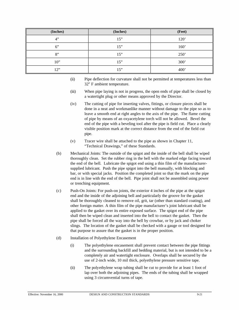
Table 9-7: Pipe Laying
Approximate Pipe Size Offset in 20-Foot Length Radius of Curve
Effective: November 16, 2000 DESIGN AND CONSTRUCTION STANDARDS 9-21
(Inches) (Inches) (Feet)
4” 15” 120’
6” 15” 160’
8” 15” 250’
10” 15” 300’
12” 15” 400’
(ii) Pipe deflection for curvature shall not be permitted at temperatures less than32o F ambient temperature.
(iii) When pipe laying is not in progress, the open ends of pipe shall be closed bya watertight plug or other means approved by the Director.
(iv) The cutting of pipe for inserting valves, fittings, or closure pieces shall bedone in a neat and workmanlike manner without damage to the pipe so as toleave a smooth end at right angles to the axis of the pipe. The flame cuttingof pipe by means of an oxyacetylene torch will not be allowed. Bevel theend of the pipe with a beveling tool after the pipe is field cut. Place a clearlyvisible position mark at the correct distance from the end of the field cutpipe.
(v) Tracer wire shall be attached to the pipe as shown in Chapter 11,“Technical Drawings,” of these Standards.
(b) Mechanical Joints: The outside of the spigot and the inside of the bell shall be wipedthoroughly clean. Set the rubber ring in the bell with the marked edge facing towardthe end of the bell. Lubricate the spigot end using a thin film of the manufacturer-supplied lubricant. Push the pipe spigot into the bell manually, with blocking andbar, or with special jacks. Position the completed joint so that the mark on the pipeend is in line with the end of the bell. Pipe joint shall not be assembled using poweror trenching equipment.
(c) Push-On Joints: For push-on joints, the exterior 4 inches of the pipe at the spigotend and the inside of the adjoining bell and particularly the groove for the gasketshall be thoroughly cleaned to remove oil, grit, tar (other than standard coating), andother foreign matter. A thin film of the pipe manufacturer’s joint lubricant shall beapplied to the gasket over its entire exposed surface. The spigot end of the pipeshall then be wiped clean and inserted into the bell to contact the gasket. Then thepipe shall be forced all the way into the bell by crowbar, or by jack and chokerslings. The location of the gasket shall be checked with a gauge or tool designed forthat purpose to assure that the gasket is in the proper position.
(d) Installation of Polyethylene Encasement
(i) The polyethylene encasement shall prevent contact between the pipe fittingsand the surrounding backfill and bedding material, but is not intended to be acompletely air and watertight enclosure. Overlaps shall be secured by theuse of 2-inch wide, 10 mil thick, polyethylene pressure sensitive tape.
(ii) The polyethylene wrap tubing shall be cut to provide for at least 1 foot oflap over both the adjoining pipes. The ends of the tubing shall be wrappedusing 3 circumvential turns of tape.

9-22 DESIGN AND CONSTRUCTION STANDARDS Effective: November 16, 2000
(iii) The loose wrap on the barrel is to be pulled snugly around the barrel of thefitting and the excess folded over at the top. This fold will be held in placeby means of two, 6- inch strips of the tape.
(iv) Valves shall be wrapped by bringing the tube wrap on the adjacent pipe overthe bells of the valve and sealing with tape. The valve bodies are thenwrapped with flat sheets passed under the valve bottom and brought uparound the body to the stem and fastened with the tape.
(2) Installation of Thrust Restraint
(a) Thrust blocks shall be poured between undisturbed solid ground and the fitting to beanchored. The area of bearing on the undisturbed trench wall shall be that shownon the thrust block detail or directed by the Director. The concrete shall be placedso that the pipe or fitting joints will be accessible for repair. A bond breaker shall beplaced over the fitting before placing concrete.
(b) Full length tie rods between joints with pipe clamps shall be assembled using clampson each side of pipe bells with tie rods extending the full pipe length for thedimensions shown on the drawings each direction from the restrained fitting, valveor joint. Clamps shall be installed tight enough to prevent twisting around the pipe. A washer shall be used at each clamp and tie rods shall be located on each side ofthe pipe. The tie rod nut should first be hand tightened with a 12-inch wrench(approximately 50-100 foot-pounds torque). Threaded tie rods shall extend two fullthreads past each nut in the final position.
(c) Follower gland type joint restraint systems shall be assembled according tomanufacturer’s instructions.
(3) Installation of Tracer Cable: Tracer wire shall be spirally wrapped around the pipeexterior, 2 wraps minimum per 20-feet of pipe, as it is installed in the trench or taped to thetop of the pipe. Splices due to breaks in wire continuity shall be made by stripping insulationcoating from each wire with wire stripper pliers. Wires shall be joined with a solderlessconnector, 3M Direct Bury Splice Kit or approved equivalent, in accordance withmanufacturers instructions. The solderless connector shall be covered with EmmersonElectric Seal-A-Conn II putty or approved equal.
The wire shall form a continuous electrical circuit between any 2 contact points on the newpipeline, including branch lines and fire hydrant laterals. Wire shall be stubbed out to thepoint where the new pipe connects to the existing main unless otherwise directed by theDirector. Where the wire terminates at a point where there is not an installed wire, the endsof the wire shall be stripped bare a minimum of 18-inches and grounded into the native soilmaterial. Special care should be taken to avoid contact from the tracer wire to steel gasservice lines.
(4) Testing Testing of PVC pressure pipe shall be as specified in Section 9.12, “Testing ofWater Pipes,” of these Standards.
(5) Backfilling and Restoring Surface Conditions: Shall be as specified in Section 9.02,“Excavation and Trenching,” of these Standards.
(6) Disinfecting Potable Pipelines: PVC pressure pipe shall be disinfected as specified Section9.11, “Disinfecting Waterlines,” of these Standards.
Effective: November 16, 2000 DESIGN AND CONSTRUCTION STANDARDS 9-23
9.05 Water Services
(A) General
(1) Scope: This section describes the furnishing and installation of water services and fire linesin the pipe diameter size range of 3/4 to 2 inches. For water services and fire lines greaterthan 2 inches in diameter refer to Section 9.03, “Ductile Iron Pipe,” Section 9.04, “PolyvinylChloride (PVC) Pressure Pipe,” Section 9.06, “Gate Valves,” and Section 9.08, “TappingSleeves and Valves,” of these Standards.
(2) Quality Assurance: Manufacturer’s certificates of compliance and installationrecommendations shall be provided to the City inspector prior to construction. Installationrecommendations shall be followed during construction.
(B) Materials
(1) Pipe: Pipe shall be Type K copper, soft drawn, in accordance with ASTM B88.
(2) Fittings: Use flared fittings to match pipe such as “Mueller” H-15400, “Ford” C22, orapproved equivalent. Use bends such as “Mueller” H-15525, “Ford” L22, or approvedequivalent.
(3) Corporation Stops: Corporation stops shall be “Mueller” H-15000, “Ford” F600, orapproved equivalent.
(4) Water Meters: Water meters, meter pit and cover, interior piping and yoke shall bepurchased from the City of Boulder.
(5) Service Saddles: Corporation stops require the installation of a double strap bronze servicesaddle, similar and equivalent to “Rockwell” No. 323, with PVC pipe or brass service saddlessimilar and equivalent to “Ford” No. S90. No direct taps to PVC pipe shall be allowed.
(6) Insulators (Ferrous Pipes only): Insulators shall be installed at the inlet end of thecorporation stop and shall be Ford Service Insulators or an approved equivalent for servicelines.

9-24 DESIGN AND CONSTRUCTION STANDARDS Effective: November 16, 2000
(C) Execution
(1) General
(a) Size as shown, lay to grades and lines in accordance with pipe manufacturer’sspecifications. Thoroughly clean pipe interiors of foreign matter before placing intotrench. Replace with new pipe any laid section of pipe found damaged or defective. All pipe fittings, valves, and appurtenances shall be installed according tomanufacturer’s instructions. Corporation stops shall be installed with theappropriate tapping machine in the presence of the Director after the waterline hasbeen pressure tested.
(b) All bedding, pipe zone backfill, compaction, polyethylene sheathing and other detailsof the water pipeline construction shall be returned to original condition after serviceconnections are completed.
(c) Service connections to all ferrous mains shall be electrically insulated by means of aCity approved insulating fitting.
(2) Pipe Cutting: Cutting shall be done neatly by methods that will not damage pipe.
(3) Water Meters: Water meters shall be installed as indicated in Chapter 11, “TechnicalDrawings,” of these Standards for all water services. Before water meters are installed, theDirector will determine the location for their placement.
(4) Testing: Testing of water service pipe shall be as specified in Section 9.12, “Testing ofWater Pipes,” of these Standards.
(5) Backfilling and Restoring Surface Conditions: Backfilling and Restoring surfaceconditions shall be as specified in Section 9.02, “Excavation and Trenching,” of theseStandards.
(6) Disinfecting Potable Pipelines: Water service pipe shall be disinfected as specifiedSection 9.11, “Disinfecting Waterlines,” of these Standards.
9.06 Gate Valves
(A) General
(1) Scope: This section describes the furnishing and installation of gate valves andappurtenances for potable water service in the pipe diameter size range of 4 to 12 inches.
(2) Quality Assurance
(a) Manufacturer’s certificates of compliance and installation recommendations shall beprovided to the City inspector prior to construction. Installation recommendationsshall be followed during construction.
(b) All valves shall be tested in accordance with AWWA C500 or C509. Certifiedcopies of the results of all tests, together with an affidavit of compliance shall beprovided to the City inspector prior to construction.

Effective: November 16, 2000 DESIGN AND CONSTRUCTION STANDARDS 9-25
(B) Materials
(1) Gate Valves: Gate valves shall be iron-bodied, resilient seat or epoxy coated double disc,with non-rising stem conforming to AWWA C500 or C509. Valves shall opencounterclockwise and shall be rated for a design working pressure of 200 psi. Double disctype valves shall be bronze mounted with parallel seats. All buried valves shall have one 2-inch square operating nut. Mechanical or push-on joints appropriate for buried installationsshall be provided. Where valves are installed at tee connections, a swivel adaptor shall beused to restrain the valve to the tee. Bolts, studs, and nuts shall be cadmium-plated or zinc-coated.
(2) Extension Stems
(a) Extension stems with a 2-inch square operating nut and a support for the upper endof the extension shall be provided for all valves installed more than 5 feet deep. Theoperating nut shall be located within 5 feet of the finished grade. Extension stemsshall be mechanically connected to the operating nut. Extension stems shall befabricated from solid steel shafting not smaller in diameter than the stem of the valveor from galvanized steel pipe having an ID not smaller than the OD of the valvestem. Extension stems shall be connected to the valve by a flexible socket typecoupling. All connections shall be pinned, keyed, or socket type. Pipe couplingswill not be acceptable.
(b) Each extension stem for a buried valve shall extend to within 6 inches of the groundsurface, shall be provided with spacers that will center the stem in the valve box,and shall be equipped with a wrench nut.
(3) Valve Boxes
(a) All buried valves shall be provided with valve boxes. Valve boxes shall be of castiron, 3 piece screw type, suitable for the depth of cover required by the drawings. Valve boxes shall be 5 ½ inches in diameter, shall have a minimum thickness at anypoint of 1/16 inch, and shall be provided with suitable cast iron bases and stay-putcovers. Covers shall have cast thereon “water” on the top. They shall be Tyler6860 series or approved equal.
(b) The valve box shall have at least 6 inches adjustment above and below specifieddepth of cover over pipe.
(c) All parts of valve boxes, bases, and covers shall be coated by dipping in bituminousvarnish.
(d) Valves and valve boxes shall be set plumb. Each valve box shall be placed directlyover the valve it serves, with the top of the box brought flush with the finishedgrade. After being placed in proper position, earth shall be filled in around eachvalve box and thoroughly tamped on each side of the box.
(4) Special Wrenches and Keys: All tools needed to operate valve and to open valve box lid. At least one of each type as required for each style and size of box and lid shall be furnishedby the contractor. Provide 1 key for each valve. Key lengths shall be as approved by theDirector.

9-26 DESIGN AND CONSTRUCTION STANDARDS Effective: November 16, 2000
(C) Execution
(1) Handling: All valves and actuators shall be transported and stored in a manner that willprotect them from damage.
(2) Installation: Install valves as indicated in Chapter 11, “Technical Drawings,” of theseStandards, and set plumb on a firm base. All foreign matter shall be removed from the valveinterior prior to installation.
(3) Valve Boxes: Install a valve box over the gate valve with the base section centered over theoperating nut and resting on well-compacted backfill. The top section shall be so set as toallow equal movement above and below finished grade, with the final elevation to be 1/4 inchbelow finished grade in roadways and 1 to 2 inches above grade outside of roadways. Thetop of base section shall be placed approximately on line with the operating nut at the top ofthe valve stem, and the entire assembly shall be plumb.
(4) Tests: Gate valve tests shall be with and part of the general tests on the companion waterlines.
(5) Disinfection: Gate valve disinfection shall be done with and as a part of the disinfection tothe companion water lines.
9.07 Butterfly Valves
(A) General
(1) Scope: This section describes the furnishing and installation of gate valves andappurtenances for potable water service in the pipe diameter size range of 12 inches to 24inches.
(2) Quality Assurance: Manufacturer’s installation recommendations and certificates ofcompliance shall be provided to the City inspector prior to construction. Installationrecommendations shall be followed during construction.
(3) Testing: All valves shall be tested in accordance with Section 3.8 of AWWA C504. Certified copies of the results of all tests, together with an affidavit of compliance shall beprovided to the City inspector prior to construction.
(B) Materials
(1) Butterfly Valves
(a) Butterfly valves shall be rubber-seated conforming to the AWWA C504 and designedfor buried service. The valves shall be designed to operate as open or closed with adesign velocity of 8 feet per second. The valves shall have a cast-iron body withmechanical joint ends conforming to ANSI 21.11, AWWA C111 and shall be ratedfor a design working pressure of 150 psi. Valves shall be manufactured byKeystone or equal.
(b) Discs shall be cast or ductile iron with stainless steel, type 304, either stub or onepiece shafts. Discs shall be secured to shafts by means of solid, smooth sided,stainless steel or monel pins or dowel pins. Each taper pin or dowel pin shall extendthrough or shall wedge against the side of the shaft and shall be mechanicallysecured in place. The use of bolts, setscrews, knurled or fluted dowel pins,

Effective: November 16, 2000 DESIGN AND CONSTRUCTION STANDARDS 9-27
expansion pins, roll pins spring pins, or other devices in lieu of the pins specifiedherein will not be acceptable.
(c) Shaft bearings shall be the bushing type of nylon or Teflon. Thrust bearings that aredirectly exposed to line liquid and that consist of a metal bearing surface in rubbingcontact with an opposing metal bearing surface will not be acceptable. Shaft sealsmay be rubber ring or chevron packing.
(d) Seats shall be rubber vulcanized to the body and designed to provide bubble tightshutoff with mating surface of Type 304 or 316 stainless steel or monel mounted onthe discs. Valve seat configurations that rely on the mating pipe flange to hold theseat in position in the valve body will not be acceptable.
(e) The valve operator shall be the traveling-nut type designed for previous statedconditions, in an enclosed body, sealed to prevent the entrance of groundwater up tothe depth of 5 feet above the valve. The operator shall have travel limiting devices toprevent over closing or opening damage to the valve. Valves shall opencounterclockwise with the use of a valve key on a 2-inch square operating nut. Thehousing of traveling-nut type actuators shall be fitted with a removable cover thatshall permit inspection and maintenance of the operating mechanism withoutremoving the actuator from the valve.
(f) Extension stems, valve boxes and special wrenches and keys shall be as specified inSection 9.06(B), “Materials,” of these Standards.
(C) Execution
(1) Handling: All valves and actuators shall be transported and stored in a manner that willprotect them from damage.
(2) Installation: Install valves with the shaft horizontal according to the manufacturer’srecommended installation procedures. Operate all valves from full open to full close beforeinstallation. Check all seats, seat rings, shaft sleeves, disc connections, etc. prior toinstallation.
(3) Valve Boxes: Install valve boxes over the valve operator with the base section centered overthe operator nut and resting on well-compacted backfill. The top section shall be set to allowequal movement above and below finished grade, with final elevations to be 1/4 inch belowfinished grade in roadways and 1 inch to 2 inches above grade outside of roadways. The topof base sections shall be placed approximately on line with the operator nut at the top of thevalve stem, and the entire assembly shall be plumb.
(4) Tests: Butterfly valve tests shall be done with and as a part of the general tests on thecompanion water lines.
(5) Disinfection: Butterfly valve disinfection shall be done with and as a part of the generaldisinfection to the companion water line.
9.08 Tapping Sleeves and Valves
(A) General
(1) Scope: This section describes the furnishing and installation of tapping sleeves and valvesfor potable water service in the pipe diameter size range of 4 inches to 12 inches.

9-28 DESIGN AND CONSTRUCTION STANDARDS Effective: November 16, 2000
(2) Quality Assurance
(a) Manufacturer’s certificates of compliance and installation recommendations shall beprovided to the City inspector prior to construction. Installation recommendationsshall be followed during construction.
(b) The manufacturer of tapping sleeves and valves shall be experienced in their designand construction, shall be regularly engaged in their manufacture, and shall haveproduced tapping sleeves and valves of the sizes specified herein that have givensuccessful service for a period of at least 5 years.
(B) Materials
(1) General
(a) All steel plate used in fabrication of the tapping sleeves shall conform to ASTMDesignation A 36 or A 285, Grade C. Tapping sleeves shall be Mueller “No. H-615"or equivalent for standard pipes and Ford “FTSS” or equivalent for oversized pipes
(b) Extension stems, valve boxes, and special wrenches and keys shall be as specified inSection 9.06(B), “Materials,” of these Standards.
(2) Flanges: Flanges shall be fabricated from steel plate, and all dimensions shall conform toAWWA Standard C207, Class D. Flanges shall be machined to a flat rate with finish of 250micro inches or machined to a flat surface with a serrated finish in accordance with AWWAStandard C207. In addition, the machined face shall also be recessed for tapping valves inaccordance with the MSS Standard SP-60.
(3) Gaskets: Gaskets shall be compounded from new materials, and the shape and cross-section of the gasket shall provide adequate seal for the design pressure. Gaskets shall beshop glued to the groove provided in the body section.
(4) Fasteners: Bolts and hex nuts shall be Stainless Steel, “Usalloy”, “Dresserloy”, “Cor-Ten”or an approved equivalent for corrosion control.
(5) Testing Outlet: A 3/4 inch NPT by welded coupling shall be attached to the outlet nozzle ofeach tapping sleeve assembly, complete with a 3/4 inch square head pipe plug.
(6) Tapping Valves: With the exception of the valve ends and other modifications necessary fortapping service, tapping valves shall be as specified in Section 9.06(B), “Materials,” of theseStandards. Each tapping valve shall be provided with a flanged inlet end designed, faced anddrilled for attachment to the outlet flange of the tapping sleeve; an outlet end provided with atapping flange for attachment of a standard drilling machine; and a mechanical joint bell endfor connection of the branch main. The size of the waterway shall include the appropriateclearance for the diameter of the tapping machine cutter recommended by the valvemanufacturer. Tapping valves shall be Mueller “No. H-667" or equal.
(7) Painting: All ferrous metal surfaces of tapping sleeves, valves and accessories, both interiorand exterior, shall be shop painted for corrosion protection. The valve manufacturer'sstandard paint will be acceptable provided it is functionally equivalent to the specified paintand is compatible with the specified field painting.
(a) Materials:
(i) Asphalt Varnish: Fed. Spec TT-V-51;
(ii) Coal Tar: Koppers “Bitumastic Super Tank Solution;”

Effective: November 16, 2000 DESIGN AND CONSTRUCTION STANDARDS 9-29
(iii) Epoxy: Mobil “78-D-7 Tank Lining Epoxy;”
(iv) Rust Preventative: Houghton “Rust Veto 344;” or
(v) Rustoleum Compound “R-9."
(b) Surfaces to be painted:
(i) Unfinished Surfaces;
(ii) Interior: Asphalt varnish (two coats), coal tar or epoxy;
(iii) Exterior (Buried or Located in Manholes): Asphalt varnish or coal tar;
(iv) Polished or Machined Surfaces: Rust preventative compound; and
(v) Operators and Accessories: Rust inhibitive primer.
(C) Execution
(1) Tapping Valves: Install tapping valves in the lines as indicated on the drawings, and setplumb on a firm base. All foreign matter shall be removed from the valve interior prior toinstallation. Valves shall be securely bolted to the tapping sleeve in accordance with themanufacturers instructions using the fasteners specified in Subsection 9.08(B)(4), above.
(2) Tests: Valve tests shall be done with and as a part of the general tests on the companionwaterlines.
(3) Disinfection: Valve disinfection shall be done with and as a part of the general disinfectionto the companion waterline.
9.09 Fire Hydrants
(A) General
(1) Scope: This section describes the furnishing and installation of fire hydrants for potablewater service.
(2) Quality Assurance
(a) Manufacturer’s certificates of compliance and installation recommendations shall beprovided to the City inspector prior to construction. Installation recommendationsshall be followed during construction.
(b) All valves shall be tested in accordance with Section 5.1 of AWWA C502. Certifiedcopies of the results of all tests, together with an affidavit of compliance shall beprovided to the City inspector prior to construction.
(B) Materials
Hydrants may be purchased from the City of Boulder Fire Department, and shall be Mueller CenturionA-423, with mechanical joint bottom connection and shall comply with AWWA C502 having thefollowing requirements:
(1) Inlet Pipe: 6 inch, mechanical joint inlet shoe and accessories
(2) Trench Depth: 4-1/2 feet cover, minimum
9-30 DESIGN AND CONSTRUCTION STANDARDS Effective: November 16, 2000
(3) Operating Nut: 1-5/8 inch pentagon
(4) Open: Left (CCW)
(5) Connection: Two 2-1/2 inch hose nozzles and one 4-1/2 inch pumper nozzle
(6) Threads: National Standard Hose Threads
(7) Pressure: 150 psi working pressure, 300 psi pressure
(8) Break-Off Flange: Hydrants shall be provided with traffic break-off flange.
(9) Color: Color shall be Rustoleum No. 831 “restful green” except for bonnet, weather capsand nozzle caps, which must be Rustoleum No. 2766 “reflectorized white.”
(10) Spare Parts: A set of spare break-off parts shall be furnished.
(C) Execution
(1) Hydrants: Where applicable, hydrants shall be installed with pumper outlet facing theadjacent roadway or parking area. Set hydrants at such elevations that the connecting pipeshall drain to the main with a grade of not less than 1 percent, and upon a concretefoundation not less than 6 inches thick and 18 inches square. The centerline of nozzles shallbe at least 18 inches above finished grade. Firmly block the back of the hydrant opposite thepipe connection with a concrete thrust block braced against the vertical face of the trench toprevent the hydrant from blowing off the line.
(2) Drainage Aggregate and Backfill: Place not less than 1/3 cubic-yard of approved cleangravel or crushed rock around the base of each hydrant and 12 inches over the top of thesupply pipe to insure drainage. A layer of 30-pound asphalt-saturated felt paper or heavyvinyl sheet shall be placed over gravel to keep backfill material from sifting into gravel. Thoroughly compact the backfill around hydrants, to the grade line, in an approved manner.
(3) Operations Check: Clean hydrant interiors of all foreign matter before installation. Stuffingboxes shall be tightened and the hydrant inspected in opened and closed positions to see thatall parts are in working condition.
(4) General: Hydrants shall be tagged “out-of-service” until the water system is operational. Itis the responsibility of the contractor to notify Boulder Police Communications regarding thelocation of the tagged hydrants.
9.10 Combination Air Valve
(A) General
(1) Scope: This section describes the furnishing and installation of combination air valves forpotable water service.
(2) Quality Assurance: Manufacturer’s certificates of compliance and installationrecommendations shall be provided to the City inspector prior to construction. Installationrecommendations shall be followed during construction.
(B) Materials
(1) Manholes: Refer to Section 9.15, “Manholes and Inlets,” of these Standards.
Effective: November 16, 2000 DESIGN AND CONSTRUCTION STANDARDS 9-31
(2) Combination Air Valve: The valve shall be a 2-inch combination air release vacuum valve,“Clow” No. 5403-B, 250 psi, or approved equivalent. The combination air valve shall beprovided with a 2-inch diameter hand wheel operated gate valve.
(3) Hose Gate Valve: A 3/4-inch hose gate valve is to be installed in the air release valvemanhole. The valve shall have a bronze body, threaded end, solid wedge, union bonnet,inside screw rising stem gate valve. These valves shall be “Powell” 375 HS. Each hose gatevalve shall be equipped with a brass cap and chain.
(4) Ball Valve: Ball valves shall be of bronze or brass construction with two-piece end entrybody, bronze or brass ball, Teflon or Viton stem seal, reinforced Teflon seats and thrustwasher, a removable operating lever, and threaded ends. Valves shall be rated not less than500 psi non-shock cold WOG and shall be drip-tight in both directions. Valves shall be“Conbraco Industries” Apollo 70-100 Series, “Powell” Fig 4210T, or “Stockham” S-216.
(5) Corporation Stop: A corporation stop shall be as referenced in Subsection 9.05(B)(3), inthis chapter.
(6) Insulators: Insulators shall be as referenced in Subsection 9.05(B)(f), in this chapter.
(C) Execution
(1) Installation: Install valve, manhole, and appurtenances as indicated on Drawing No. 5.22,in Chapter 11, “Technical Drawings,” of these Standards, and in accordance with applicableprovisions of the related sections.
(2) Tests: Valve tests shall done be with and as a part of the general tests on the companionwaterlines.
(3) Disinfection: Valve disinfection shall be done with and as a part of the general disinfectionto the companion waterlines.
9.11 Disinfecting Waterlines
(A) Scope
This section describes the disinfecting of all portions of the potable water system, including buriedpiping, valves, hydrants, and any portion of the existing connecting system that might have becomecontaminated during construction activities, and also any temporary water service piping used duringconstruction.
(B) Materials
(1) Chlorinating Material: The chlorinating material shall either be a hypochlorite solution,tablets or granules.
(2) Tablet Attachment: The hypochlorite tablets shall be fastened to the top of the pipe usingPermatex No. 1.
(C) Execution
(1) Disinfection

9-32 DESIGN AND CONSTRUCTION STANDARDS Effective: November 16, 2000
(a) Care shall be taken to prevent contaminating materials from entering the water mainsduring construction or repair. Such materials that may accidentally enter the mainshall be removed by flushing. This flushing shall be done prior to disinfection unlessthe tablet method of disinfection is used. If, in the opinion of the Director, thecontaminated material that has entered cannot be removed by flushing, the interior ofthe pipe shall be cleaned by mechanical means and then swabbed with a 1 percenthypochlorite solution.
(b) Upon completion of the water pipelines, all new pipe, valves, hydrants, etc. shall bethoroughly flushed and disinfected, using a continuous-feed method of hypochloriteand water mixture or hypochlorite tablets or granules in accordance with AWWAStandard C-651, latest revision.
(c) The chlorinating material shall be introduced into the water lines and distributionsystems in a manner approved by the Director. After a contact period of not lessthan 24 hours, the treated water in the lines shall contain not less than 10 mg perliter chlorine using the continuous-feed method or 25 mg per l chlorine using thetablet or granular method throughout the length of the line. The system shall beflushed after successful completion of disinfection with clean water until the residualchlorine content is no more than 1.0 mg per liter. All valves in lines beingdisinfected, except those being used as bulkheads, shall be opened and closedseveral times during the contact period. During flushing and disinfection thecontractor shall make sure that none of the disinfection solution enters any existingwater main.
(d) Flushing shall be done with a flushing velocity of at least 2 ½ feet per second. Thecontractor shall provide all fittings required to flush the line. Flushing will beaccomplished in such a manner that no erosion will occur and there will be nodamage to street, fish, animals, plants or other property.
(2) Bacteriological Examination: After the system has been thoroughly flushed and before thenew water line is connected to the distribution system, samples shall be taken fromrepresentative points in the system, at intervals of 1200 feet, in sterile bottles treated withsodium thiosulfate. Labeled samples shall be submitted to the City Drinking Water Programstaff, or designated certified laboratory, for bacteriological examination. Submitted samplesshall meet all City and State bacteriological standards, showing the absence of both coliformand heterotrophic bacterial growths. If the initial disinfection fails to produce satisfactorybacteriological results, the new main shall be reflushed and resampled. If check samples alsofail to produce acceptable results, the main shall be rechlorinated by the continuous feed orslug method until satisfactory results are obtained.
(3) Disposal of Solution: Following testing, the solution and flushing water shall be disposed ofby the contractor into the nearest sanitary sewer line. The solution and flushing water shallnot be dumped into any lakes, streams, waterways, irrigation ditches or stormwater drainagesystems. If wasted water cannot be safely discharged into a sanitary sewer system, andthen a reducing agent shall be applied to the wasted water to thoroughly neutralize thechlorine residual remaining in the water.
9.12 Testing of Water Pipes
(A) General
This section describes the testing of all water pipe including water mains, fire lines and services.

Effective: November 16, 2000 DESIGN AND CONSTRUCTION STANDARDS 9-33
(B) Materials
The contractor shall provide all necessary test equipment including test pumps, pipe, connectors,meters, gauges, instruments, and other equipment required. Pressure gauges used shall be graduatedin increments no more than 5 psi and shall have a range of approximately twice the test pressure. Gauges meters and other instruments shall be calibrated prior to testing.
(C) Execution
(1) Notification and Witness
(a) The contractor shall notify the Director of all tests at least 48 hours prior to testingso that the Director can witness the tests.
(b) The pipe may be subjected to hydrostatic pressure and inspected and tested forleakage at any convenient time after the trench has been partially backfilled, exceptat the joints, or backfilled as permitted by the Director. Where any section isprovided with concrete thrust blocks, the pressure test shall not be made until atleast 2 days have elapsed after the concrete was installed.
(2) Pressure Test
(a) All new pipe shall be pressure tested prior to connection to the existing system. Allpipe shall be tested at a pressure of 150 psi at the lowest point in each section or 1½times the working pressure, whichever is greater.
(b) Prior to testing, all equipment that would be damaged by the test pressure shall beremoved. This equipment shall be replaced in the system after testing is complete.All pipe and appurtenances shall be backfilled except for joints unless otherwisepermitted by the Director.
(c) The contractor shall slowly fill the pipe with water prior to testing and remove all airfrom the piping system. Each valved section, unless otherwise directed by theDirector, shall be tested prior to connection to the existing system. The duration ofeach pressure test shall be at least 2 continuous hours. Test time will be accruedonly while full test pressure is on the system. All water used in testing the pipelinesshall be provided by the contractor from a potable water source.
(d) The specified test pressure shall be applied by means of a pump connected to thepipe in a manner satisfactory to the Director. The contractor shall furnish allnecessary labor, equipment, and connection corporation stops to the pipeline toperform the test.
(e) No testing shall be permitted against valves or fittings that are part of the existingsystem unless specifically approved by the Director. All exposed pipes, fittings,valves, hydrants, and joints will be carefully examined during the test. Any crackedor defective pipe, fittings, valves, or hydrants discovered during the pressure testshall be removed and replaced by the contractor with sound material. The test shallbe repeated until the test is satisfactory to the Director.
(3) Leakage Test
(a) A leakage test shall be conducted after the pressure test has been completed, unlessthe pressure test indicates that there are no leaks. The contractor shall furnish thepump, pipe, connections, meters and all other necessary apparatus, and shall furnishall necessary assistance to conduct the test. The duration of each leakage test shall
9-34 DESIGN AND CONSTRUCTION STANDARDS Effective: November 16, 2000
be two hours, and, during the test, the main shall be subjected to a hydrostaticpressure specified.
(b) No pipeline installation will be accepted until the leakage is less than the amountcomputed by the following formula:
L = SD(P)0.5
133,200
Where: L = Allowable Leakage (Gallons Per Hour)
S = Tested Length of Pipe (Feet)
D = Nominal Diameter of Pipe (Inches)
P = Average Test Pressure During the Test (psi)
(c) The contractor shall, at their own expense, locate and repair the points of leakageuntil the leakage is within the specified allowance.
9.13 Polyvinyl Chloride (PVC) Non-pressure Pipe
(A) General
(1) Scope: This section describes the furnishing and installation of polyvinyl chloride (PVC)non-pressure pipe and appurtenances for storm drains, sanitary sewer mains and sewerservices in the pipe diameter size range of 4" to 15".
(2) Quality Assurance: Manufacturer’s certificates of compliance and installationrecommendations shall be provided to the City inspector prior to construction. Installationrecommendations shall be followed during construction.
(B) Materials
(1) PVC Non-pressure Pipe
(a) PVC non-pressure pipe shall be type PSM polyvinyl chloride (PVC) having a cellclassification of 12454-B or 12454-C or 13364-B (with a minimum tensile modulesof 500,000 psi) as defined in ASTM D1784. All PVC pipe and fittings shall meet orexceed all of the material requirements of ASTM D3034 and thickness requirementsof SDR 35.
(b) Provisions must be made for contraction and expansion at each joint with a rubberring and integral thickened bell as part of each joint. Gaskets shall conform toASTM F477. Pipe shall be supplied in laying lengths of 19-1/2 to 20 feet. All pipeand fittings shall be assembled with a non-toxic lubricant. Each length of pipe andall fittings shall have marked on the exterior the following:
(i) Manufacturer’s Name or Trademark;
(ii) Nominal Pipe Size;
(iii) PVC Cell Classification (e.f. 12454-B);
(iv) Legend - Type PSM SDR-35 Sewer Pipe; and
(v) ASTM - D3034.

Effective: November 16, 2000 DESIGN AND CONSTRUCTION STANDARDS 9-35
(c) All fittings and plugs to be used with the PVC pipe shall be those manufactured bythe manufacturer of the pipe. Each special fitting shall be a completelymanufactured unit with either bells or spigots on each connection that are an exactduplication of the bells and spigots on the pipeline. Fittings with any other type ofconnections will not be accepted.
(2) Plugs: Plugs shall be specifically manufactured for the pipelines where they are to beinstalled. The plug shall be constructed of a material approved by the Director and shallprovide a permanent watertight installation without permanently sealing the joint.
(3) Couplings
(a) Couplings shall be used only where shown on the approved drawings or whereapproved in writing by the Director. The contractor shall provide a description ofan exact location of any couplings used.
(b) Flexible couplings shall consist of a rubber gasket or boot, stainless steel tighteningbands. The coupling shall conform to requirements of ASTM C425 and shall be“Mission” ARC or approved equivalent.
(4) Grout
(a) Grout shall conform to the specifications defined in Section 9.15(B)(e). Thecontractor may substitute a two-component, 100 percent solids epoxy resin(Sikadur Hi-Mod LV) for the specified grout.
(b) Grout used for sealing service connections shall be a 2-component, waterproofepoxy grout specifically manufactured for this application. The grout shall adhere toany of the dissimilar materials.
(5) Sealants: Sealants used on manholes or pipe connections shall be equal to SIKAFLEX-la, aone component polyurethane base, elastomeric sealant. When required due to moisture orimmersion, provide SIKAFLEX 429 primer for application onto the substrate according tomanufacturer’s recommendation.
(C) Execution
(1) General
(a) Each pipe length and fitting interior, interior surface of bells, and exterior surface ofspigots shall be cleaned of all foreign material before placement in the trench andshall be kept clean at all times thereafter. Each item shall also be examined forcracks and other defects before installation.
(b) Pipe shall be cut, only whenever necessary, to conform to location of manholes orconnections. All cuts shall be straight, true, and at right angles to the axis of thepipe. The cutting process shall leave a smooth end without damaging the pipe. Allburrs shall be removed from the ends of cut pipe, and the end lightly rasped or filed. All tools used in cutting pipe will be subject to the Director’s approval.
(c) Pipe laying shall proceed with the spigot ends of pipe pointing in the direction of theflow, unless otherwise approved by the Director. Each pipe length shall be laid trueto line and grade in such manner as to form a close concentric joint with theadjoining pipe and to prevent sudden offsets to the flow line. Pipe shall be laid in adewatered trench and shall not be used for draining water from the trench. Do notlay pipe when trenches or weather conditions are unsuitable for such work.

9-36 DESIGN AND CONSTRUCTION STANDARDS Effective: November 16, 2000
(d) Whenever the pipe is left unattended or pipe laying is not in progress, temporaryplugs shall be installed at all openings. Temporary plugs shall be watertight and ofsuch design as to prevent debris and animals from entering the pipe. All temporaryplugs will be subject to approval by the Director.
(e) The contractor shall install the materials in accordance with the manufacturer’srecommendations. If there is a conflict between the methods prescribed in theapproved plans and the manufacturer’s instructions, the contractor shall obtainresolution from the Director, before proceeding with the work.
(2) Pipe Installation
(a) Pipe Laying:
(i) No deflection in the joints shall be allowed. All pipe shall be fully supportedalong the full length of pipe barrel without support by the bell mounding.
(ii) When curved sewers are approved in the construction plans, the alignmentcurve shall be completed by installing the pipes on uniform curves bydeflecting the pipe barrel. The minimum curves are shown in Table 9-8,“Curvilinear Sewer Pipe Laying,” of these Standards.
Table 9-8: Curvilinear Sewer Pipe Laying
Pipe Diameter (Inches) Minimum Radius (Feet) Offset 20' Length (Inches)
4 150 16
6 200 12
8 250 10
10 300 8
12 350 7
15 400 6
(b) Pipe Joints
(i) The outside of the spigot and the inside of the bell shall be thoroughly wipedclean. Set the rubber ring in the bell with the marked edge facing towardthe end of the bell. Lubricate the spigot end using a thin film of themanufacturer-supplied lubricant. Push the pipe spigot into the bell. Positionthe completed joint so that the mark on the pipe end is in line with the endof the bell.
(ii) Bevel the end of cut pipe with a beveling tool after the pipe is field cut. Place a clearly visible position mark at the correct distance from the end ofthe field-cut pipe.
(3) Connection of Pipe to Concrete Manhole Base
(a) The pipe shall be encased in the concrete poured for the manhole base as detailed inDrawing No. 6.01, “Standard Sewer Manhole,” in Chapter 11, “TechnicalDrawings,” in these Standards. Special provisions shall be made for water tightnessof the connection.

Effective: November 16, 2000 DESIGN AND CONSTRUCTION STANDARDS 9-37
(b) The exterior circumference of the pipe where encased in concrete for watertightness shall be uniformly roughened or scarified by sanding with coarsesandpaper or emery cloth for at least 6 inches encased length.
(c) Additionally, gasket as specified elsewhere shall be stretched onto the pipe to form aweep ring where encased in concrete. Any alteration to the above specified methodsfor pipe connection to concrete shall be submitted to the Director for approval.
(4) Grouting
(a) Any opening between the manhole wall and pipe made during construction shall beclosed and sealed with watertight grout. The opening shall be of sufficient size toaccommodate the pipe, “O” rings, and grout. The grout shall extend no less than thefull width of the manhole barrel.
(b) Channels that have been cut into concrete bases shall be smoothed to the specifiedcontour with grout. The grout shall extend no less than the full width of themanhole barrel.
(5) Temporary Plugs: Where required on construction plans and at the end of each sewerservice stub out, the pipe shall be sealed with a removable plug. Plugs shall be specificallymanufactured for the pipelines where they are to be installed. The plug shall be constructedof a material approved by the Director and shall provide a permanent watertight installationwithout permanently sealing the joint.
(6) Sewer Services: The general location of the sewer service lines is detailed in Drawing No.6.06, “Sewer Service Line,” in Chapter 11, “Technical Drawings,” in these Standards. Actual locations of the service lines shall be determined by the approved construction plansand in the field by the Director. The contractor shall notify the Director prior toconstructing each sewer main so that the Director may have adequate time to determine thefinal location of each service tee or wye fitting to be installed in the sewer main. Failure ofthe contractor to properly notify the Director as noted above may result in the contractor’sremoval of any portion of the sewer main that is necessary to install the fittings in theirproper location as determined by the Director.
(a) The contractor will be allowed to tap and install a service saddle to new sewer mainsonly at those locations approved by the Director. Connections onto sewer mainsshall be made only by boring or drilling with equipment designed for this purpose. Connections shall not be made by impact equipment. The contractor shall request, inwriting, Director approval of methods and equipment proposed to be used forperforming connections.
(b) The contractor shall remove from the sewer main all debris created by makingconnections before the service line is connected.
(c) Service line saddle connections shall be attached to the sewer main with an epoxy-bonding agent. The bonding agent shall be applied to a clean, dry surface. Theconnection shall remain dry until the bonding material has set, depending uponenvironmental conditions. Backfill around the connection shall not be attempted untilthe material has hardened and been accepted by the Director.
(d) At the end of all sewer services, the contractor shall provide plugs and furnish andset two marker posts. One marker post shall be buried at least 3 feet and shallextend at least 2 feet above the ground surface and shall have a piece of greenflagging at the top or be painted green. The second marker shall extend from the

9-38 DESIGN AND CONSTRUCTION STANDARDS Effective: November 16, 2000
end of the service to 18 inches below the existing surface. The marker posts shallbe wood 2 x 4, 4 x 4 or #4 rebar.
(7) Backfilling and Restoring Surface Conditions: Shall be as specified in Section 9.02,“Excavation and Trenching,” of these Standards.
(8) Testing Testing of PVC non-pressure pipe shall be as specified in Section 9.16, “Testing ofGravity Sewer Pipelines and Manholes,” of these Standards.
9.14 Reinforced Concrete Pipe
(A) General
(1) Scope: This section describes the furnishing and installation of reinforced concrete pipe andappurtenances for culverts, storm drains and sewers in the pipe diameter size range of 12inches to 144 inches.
(2) Quality Assurance:
(a) Manufacturer’s certificates of compliance and installation recommendations shall beprovided to the City inspector prior to construction. Installation recommendationsshall be followed during construction.
(b) The pipe will be tested by the manufacturer based on the three-edge bearing test forboth the 0.01 inch crack and the ultimate strength as set forth in ASTM C-497. Thepipe shall be tested at the manufacturer’s plant. Not more than 1 percent of thenumber of pipe lengths, but no fewer than two pipes, for each size of pipe, will betested. The contractor shall provide copies of the test results to the Director forapproval. The Director may select pieces to be tested.
(B) Materials
(1) Reinforced Concrete Pipe
(a) The reinforced concrete pipe shall comply with the requirements of ASTM C76. The pipe shall be Class III unless noted otherwise on the approved constructionplans. The cement for the pipe shall conform to the requirements set forth in ASTM150 and shall be type II and shall have a minimum compressive strength of 4,000psi. All wall thicknesses shall be those established in “Wall B” in table 3, of said C76specification, and the reinforcement shall be shown in the same “Wall B.” Eachsection, or “stick”, of pipe shall be 7 feet-6 inches or greater in length.
(b) No elliptical reinforcement will be permitted except for any elliptical reinforcedconcrete pipe designated on the construction plans.
(c) Lifting holes will not be permitted in any of the pipe. The following shall be clearlymarked on the exterior surface of the pipe:
(i) ASTM Specification;
(ii) Date of manufacture;
(iii) Class and size; and
(iv) Name or trademark of manufacturer.
Effective: November 16, 2000 DESIGN AND CONSTRUCTION STANDARDS 9-39
(d) The joint design shall be tongue and groove, or bell and spigot. Joints for thecircular reinforced concrete pipe shall be all rubber gasket conforming to ASTM C-443, latest revision. The gasket shall be attached to the spigot of the pipe and shallmake the joint flexible and watertight. The contractor may use butyl mastic jointsealant in rope or trowel applied form in lieu of rubber gaskets for circular pipe ifapproved in writing by the Director. For all non-circular pipe and culverts, butylmastic joint sealant may be used. The contractor shall submit test results andmaterial specifications on the sealant to the Director before the Director giveswritten approval of its use. This sealant shall be made specifically for permanentlysealing joints in tongue and groove concrete sewer pipe, must adhere tightly to thepipe surface, and form a tight flexible joint. The gaskets or sealants shall be installedas directed by the manufacturer of the pipe.
(e) Flared end sections, bends and tees shall comply with the requirements of ASTMC76 and shall be the same class and shall have the same joint design as the pipedescribed above.
(f) Visual inspections of all materials shall be made at the job site, and pipe will berejected on account of any deficiencies covered by ASTM Specification DesignationC76 or on account of the following:
(i) Porous spots, inside or outside, having a greater area than 10 square inchesand a depth of more than 1/4 inch;
(ii) Patched or repair of porous spots or other defects that are not approved bythe Director; or
(iii) Exposure of reinforcement that indicates the reinforcement has beenreplaced.
(C) Execution
(1) Laying Pipe
(a) All materials shall be carefully lowered into the trench piece-by-piece by means of aderrick, ropes or other suitable tools or equipment, in such a manner as to preventdamage. Under no circumstances shall materials be dropped or dumped into thetrench. All pipe shall be inspected for defects prior to installation. Any defective,damaged or unsound pipe shall be rejected.
(b) All foreign matter or dirt shall be removed from the inside of the pipe and fittingsbefore the pipe is lowered into its position in the trench. Every precaution shall betaken to prevent foreign material from entering the pipe while it is being placed in thetrench. If the pipe-laying crew is unable to place the pipe into the trench withoutgetting foreign matter or dirt into it, the Director may require that, before loweringthe pipe into the trench, a heavy, tightly woven canvas bag of suitable size be placedover each end and left there until the connection is to be made to the adjacent pipes.
(c) An approved snug-fitting stopper or plug shall be installed in each pipe immediatelyafter it is laid and prior to any further excavating, or backfilling. All openings alongthe line of the main shall be securely closed as directed and, in the suspension ofwork at any time, stoppers shall be placed to prevent dirt or other substances fromentering the main. During laying operations, no debris, tools, clothing or othermaterials shall be placed in the pipe.

9-40 DESIGN AND CONSTRUCTION STANDARDS Effective: November 16, 2000
(d) Pipes shall be laid to a true line and at uniform rates of grade between manholes asshown on the approved construction plans. Fine grading to the bottom of the barrelshall proceed ahead of the pipe laying. The grade shall be accurately established foreach joint by laser beam, or other means approved in writing by the Director. Thelaser beam shall be checked with a level each time it is moved and each day beforeconstruction proceeds, and thereafter as required to assure that it is set at thecorrect alignment. If any errors of grade are observed, pipe laying shall stop untilthe grade is corrected.
(e) Pipe laying shall proceed upgrade with the spigot ends pointed in the direction offlow. No pipe shall be laid in water or when the trench conditions are unsuitable forsuch work. The contractor shall make all connections of pipe to the manholes thathave previously been constructed. When connecting to existing sewers, thecontractor shall take every precaution necessary to prevent dirt or debris fromentering the existing lines.
(f) Bedding shall be placed under and on both sides of the pipe as each length of sewerpipe is installed.
(2) Joining Pipe
(a) Use a method of joining pipe sections that ensures that ends are fully entered andinner surfaces are flush and even. The equipment used to force the joints togethermust be adequate enough to overcome the gasket pressure involved.
(b) Just prior to joining the pipes, the ends of the pipe shall be thoroughly cleaned with awire brush to remove all foreign substances that may have adhered to the pipesurface. All dust and dirt shall be removed with a clean rag. A lubricating solutionthat is not injurious to the gasket or concrete, such as flax soap or water glass, shallbe liberally applied to the gasket groove and to the entire surface of the bell ring. Following this operation, a thin film of lubricant shall be applied to the gasket thatshall then be snapped into place in the groove, after which a small diameter smoothsteel rod shall be inserted between the gasket and groove and run completely aroundthe gasket to equalize the gasket tension.
(c) In the event that any foreign matter becomes imbedded in the lubricant, or thelubricant becomes contaminated by water or other substances before the joint isstarted, the area affected shall be re-cleaned and new lubricant shall be applied.
(d) The pipe being jointed shall be carefully moved into position, be line and gradechecked, and as the spigot end is started into the bell of the section previously laid,the gasket position shall be checked to ensure uniform entry into the bell at allpoints.
(3) Testing and Flushing Pipe
(a) Prior to acceptance of each section of storm sewer line, the contractor shall jetclean all sewers up through 18 inches in diameter. Larger storm sewers shall becleaned by other appropriate methods approved by the Director. All dirt and debrisshall be prevented from entering the existing storm sewer system by means ofwatertight plugs or other suitable methods.
(b) If the Director finds it necessary to clean the mains immediately after constructionby rodding, jetting, or both, the Director shall assess the contractor for the cleaningat a set per foot charge with a minimum dollar amount.

Effective: November 16, 2000 DESIGN AND CONSTRUCTION STANDARDS 9-41
(c) The Director will televise all mains as part of public inspection, and will bill thecontractor for the televising at a set per foot charge with a minimum dollar amount. Any defects found during the televising shall be repaired by the contractor, in amanner approved by the Director.
(d) Any visible infiltration, that the Director finds to be the result of poor installation ofthe specified materials, shall be repaired by the contractor in a manner approved bythe Director before the work will be accepted.
(e) Before acceptance of the work, the Director will survey the manhole invert andsurface elevations. Any inverts or surface elevations not meeting the approveddesign in the construction plans shall not be approved and shall be redone to thesatisfaction of the Director.
(f) Upon completion of construction, the Director will carefully inspect all sewers andappurtenances. Any unsatisfactory work shall be removed and replaced by thecontractor in a proper manner. The invert of sewer and manholes shall be leftsmooth, clean, and free from any obstructions throughout the entire line. Manholerings and covers must be raised to finished grade before final acceptance of thesewer.
(g) For sanitary sewers, testing shall be as specified in Section 9.16, “Testing of GravitySewer Pipelines and Manholes,” of these Standards.
9.15 Manholes and Inlets
(A) General
(1) Scope: This section describes the furnishing and installation of precast concrete manholes,storm sewer inlets and appurtenances.
(2) Quality Assurance: Manufacturer’s certificates of compliance and installationrecommendations shall be provided to the City inspector prior to construction. Installationrecommendations shall be followed during construction.
(B) Materials
(1) General
(a) Manholes shall be constructed of precast concrete riser sections, in accordance withDrawing No. 6.01, “Standard Sewer Manhole,” in Chapter 11, “TechnicalDrawings,” of these Standards. The concrete sections shall conform to ASTMC478. The top section required for change of diameter shall be concentric cone orflat slab. Invert channel shall be smooth and semicircular in shape conforming tothe inside of the adjacent sewer section. The minimum internal diameter of themanhole barrel shall be in Table 9-9, “Required Manhole Diameters,” for all manholeinstallations:
Table 9-9: Required Manhole Diameters
Pipe Size (Diameter) Inner Manhole Section Diameter
18 Inches (and Smaller) 4 Feet
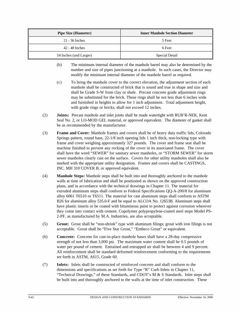
9-42 DESIGN AND CONSTRUCTION STANDARDS Effective: November 16, 2000
Pipe Size (Diameter) Inner Manhole Section Diameter
21 - 36 Inches 5 Feet
42 - 48 Inches 6 Feet
54 Inches (and Larger) Special Detail
(b) The minimum internal diameter of the manhole barrel may also be determined by thenumber and size of pipes junctioning at a manhole. In such cases, the Director maymodify the minimum internal diameter of the manhole barrel as required.
(c) To bring the manhole cover to the correct elevation, the adjustment section of eachmanhole shall be constructed of brick that is sound and true in shape and size andshall be Grade S-W from clay or shale. Precast concrete grade adjustment ringsmay be substituted for the brick. These rings shall be not less than 6 inches wideand furnished in heights to allow for 1 inch adjustment. Total adjustment height,with grade rings or bricks, shall not exceed 12 inches.
(2) Joints: Precast manhole and inlet joints shall be made watertight with RUB’R-NEK, KentSeal No. 2, or LO-MOD GEL material, or approved equivalent. The diameter of gasket shallbe as recommended by the manufacturer.
(3) Frame and Cover: Manhole frames and covers shall be of heavy duty traffic lids, ColoradoSprings pattern, round base, 22-1/8 inch opening lids 1 inch thick, non-locking type withframe and cover weighing approximately 327 pounds. The cover and frame seat shall bemachine finished to prevent any rocking of the cover in its associated frame. The covershall have the word “SEWER” for sanitary sewer manholes, or “STORM SEWER” for stormsewer manholes clearly cast on the surface. Covers for other utility manholes shall also bemarked with the appropriate utility designation. Frames and covers shall be CASTINGS,INC. MH 310 COVER B, or approved equivalent.
(4) Manhole Steps: Manhole steps shall be built into and thoroughly anchored to the manholewalls at time of fabrication and shall be positioned as shown on the approved constructionplans, and in accordance with the technical drawings in Chapter 11. The material forextruded aluminum steps shall conform to Federal Specifications QQ-A-200/8 for aluminumalloy 6061 T6510 or T6511. The material for cast aluminum steps shall conform to ASTMB26 for aluminum alloy 535.0-F and be equal to ALCOA No. 12653B. Aluminum steps shallhave plastic inserts or be coated with bituminous paint to protect against corrosion whereverthey come into contact with cement. Copolymer polypropylene-coated steel steps Model PS-2-PF, as manufactured by M.A. Industries, are also acceptable.
(5) Grout: Grout shall be “non-shrink” type with aluminum filings; grout with iron filings is notacceptable. Grout shall be “Five Star Grout,” “Embeco Grout” or equivalent.
(6) Concrete: Concrete for cast-in-place manhole bases shall have a 28-day compressivestrength of not less than 3,000 psi. The maximum water content shall be 0.5 pounds ofwater per pound of cement. Entrained and entrapped air shall be between 4 and 9 percent. All reinforcement shall be standard deformed reinforcement conforming to the requirementsset forth in ASTM, A615, Grade 60.
(7) Inlets: Inlets shall be constructed of reinforced concrete and shall conform to thedimensions and specifications as set forth for Type “R” Curb Inlets in Chapter 11,“Technical Drawings,” of these Standards, and CDOT’s M & S Standards. Inlet steps shallbe built into and thoroughly anchored to the walls at the time of inlet construction. These
Effective: November 16, 2000 DESIGN AND CONSTRUCTION STANDARDS 9-43
steps shall conform to the requirements for manhole steps, and shall be positioned as shownon the technical drawings.
(C) Execution
(1) Construction of Manholes
(a) Concrete bases shall be poured on undisturbed ground. Pipe sections shall be flushon the inside of the structural wall (except as noted below) and project outsidesufficiently for proper connection to the next pipe section. All pipelines into amanhole shall have a joint located no more than 12 inches from the exterior wall. Where incoming pipes enter a storm drain manhole at an elevation 3 feet or greaterabove the base, the incoming pipe shall project 2 inches inside the manhole. Allannular spaces around the pipe opening shall be grouted.
(b) For all precast manhole bases, the ground surface below precast concrete basesshall be excavated 6 inches below the elevation of the bottom of the base andbackfilled with bedding material, meeting the requirements of Subsection 9.02(B) ofthese Standards. The bedding material shall be carefully leveled and smoothed as togive uniform support to the precast base over its entire area.
(c) The invert channels of manholes shall be constructed in accordance with theDrawing No. 6.03, “Manhole Invert,” in Chapter 11, “Technical Drawings,” of theseStandards. They shall be smooth and semicircular in shape, conforming to theinside of the incoming and outgoing sewer pipelines. Changes in direction of flowshall be made with a smooth curve of as large a radius as the size of the manholewill permit. Where differences of 24 inches or less in invert elevations are calledfor, sloped flow channels shall be formed so the water does not undergo a verticaldrop. A drop manhole shall be installed where the specified distance in the manholeinverts exceeds 24 inches. The inlet channels may be formed directly in theconcrete of the manhole base. The floor of the manhole outside of the channel shallbe smooth and shall slope towards the channel not less than 1 inch per foot normore than 2 inches per foot. The manhole covers shall be set with a final elevationof 1/4 inch below the finished grade in roadways and 1 to 2 inches above gradeoutside of roadways. When a manhole is located in the pavement area, it shall notbe constructed to final grade until the pavement has been completed, unless directedotherwise by the Director.
(d) Install joint material per manufacturer’s instructions so that no voids are present. Grout all joints inside and outside after manhole assembly is completed.
(e) Gaskets for connecting PVC pipe to manhole sections shall be specificallymanufactured for that purpose. The gasket shall provide for at least five bearingpoints on the pipe surface. The interior circumference of the gasket shall beapproximately 5 percent less than the exterior circumference of the pipe. Thegasket shall be as manufactured by Hamilton Kent Mfg. Co. of Kent, Ohio, orapproved equivalent. All annular spaces around pipe openings must be grouted.
(f) Stubs shall be provided at manholes when indicated on the construction plans. Suchstubs shall be sealed with a removable plug. Plugs shall be specificallymanufactured for the pipelines where they are to be installed. The plug shall beconstructed of a material approved by the Director and shall provide a permanentwatertight installation.

9-44 DESIGN AND CONSTRUCTION STANDARDS Effective: November 16, 2000
(2) Adjusting Manhole Tops: When grade adjustment of an existing structure is specified,remove frames and covers and reconstruct as required. Reset cleaned frames at theindicated elevation. Prior to final acceptance, clean structures of accumulations of silt,debris, or foreign matter.
(3) Testing Manholes: Refer to Section 9.16, “Testing of Gravity Sewer Pipelines andManholes,” of these Standards.
9.16 Testing of Gravity Sewer Pipelines and Manholes
(A) General
This section describes the testing of gravity sewer pipelines and manholes including sanitary sewersand storm drains.
(B) Materials
The contractor shall provide all equipment and material specifically designed for the testing specifiedin this section.
(C) Execution
(1) Notification and Witness: The contractor shall notify the Director of all tests at least 48hours prior to testing so that the Director can witness the tests.
(2) When to Test: The pipe shall be tested for leakage after the pipe installation and the trenchhas been partially backfilled, except at the joints, or backfilled as permitted by the Director. Where any section is provided with concrete thrust blocks, the pressure test shall not bemade until at least 2 days have elapsed after the concrete was installed.
(3) Testing Procedures
(a) General: The contractor shall flush the pipelines, as the work progresses, bymeans that are in accordance with good construction practice, to insure that earth,sand, rocks, or other foreign materials are removed from the interior of the pipeline. Care shall be taken to insure that foreign material is not transported downstreaminto the existing system.
(b) Alignment and Grade: Gravity sewer pipelines will be checked by the Director todetermine whether any displacement of the pipe has occurred after the trench hasbeen bedded to an elevation 6 inches above the pipe and tamped as specified. Thetest will be as follows:
(i) A light will be flashed between manholes, or if the manholes have not as yetbeen constructed, between the locations of the manholes, by means of aflashlight or by reflecting sunlight with a mirror. If the illuminated interiorof the pipeline shows poor alignment, displaced pipe, earth, or other debrisin the pipe, or any other kinds of defects, as determined by the Director,these deficiencies shall be corrected at the contractor’s expense. The testwill be repeated after completion of backfilling.
(ii) For sewers on curved alignment, a heavy rubber ball shall be passedthrough the pipe between manholes, or the location of manholes if notconstructed, after the pipe has been laid and backfilled. The outside

Effective: November 16, 2000 DESIGN AND CONSTRUCTION STANDARDS 9-45
diameter of the ball shall be the same as the inside diameter of the sewerpipe. The ball shall be placed at the upper manhole of the sewer to becleaned. A head of water shall be placed against the ball to force the ballthrough the sewer and debris flushed from the line shall be collected at thelower manhole, or its location. The ball shall be secured by a line to controlthe rate at which the ball is allowed to pass through the sewer.
(4) Air Tests
(a) Air testing of sanitary sewer pipes shall be done on all sections of pipe betweenmanholes. The pipe shall be cleaned and may be wetted before air testing. Thesection of pipeline being tested shall be plugged at each manhole with pneumaticballs.
(b) Low-pressure air shall be introduced into the plugged line until an internal pressureof 4 psig greater than the average backpressure of any ground water pressure thatmay submerge the pipe would cause. At least 2 minutes shall pass to allow airtemperature to stabilize before the test time is started.
(c) No pipeline installation will be accepted if the pressure drops 0.5 psig or more duringthe time and for the length of pipe shown in Table 9-10, “Specifications for AirTesting of Sanitary Sewer Pipes,” of these Standards:
(d) If the pipeline installation fails the air test, repairs shall be made and the pipe shall beretested until it passes the air test.
(5) Deflection
(a) All PVC non-pressure pipes shall be tested for vertical deflection after placement andcompaction of backfill. The maximum deflection allowed is 5 percent.
(b) Method of testing shall be by deflectometer of the rigid GO/NO-GO type device. Any and all pipe with vertical defection greater than the allowable shall be excavated,and removed from the pipeline, replaced, backfilled and compacted as specified, andretested at the contractor’s expense.
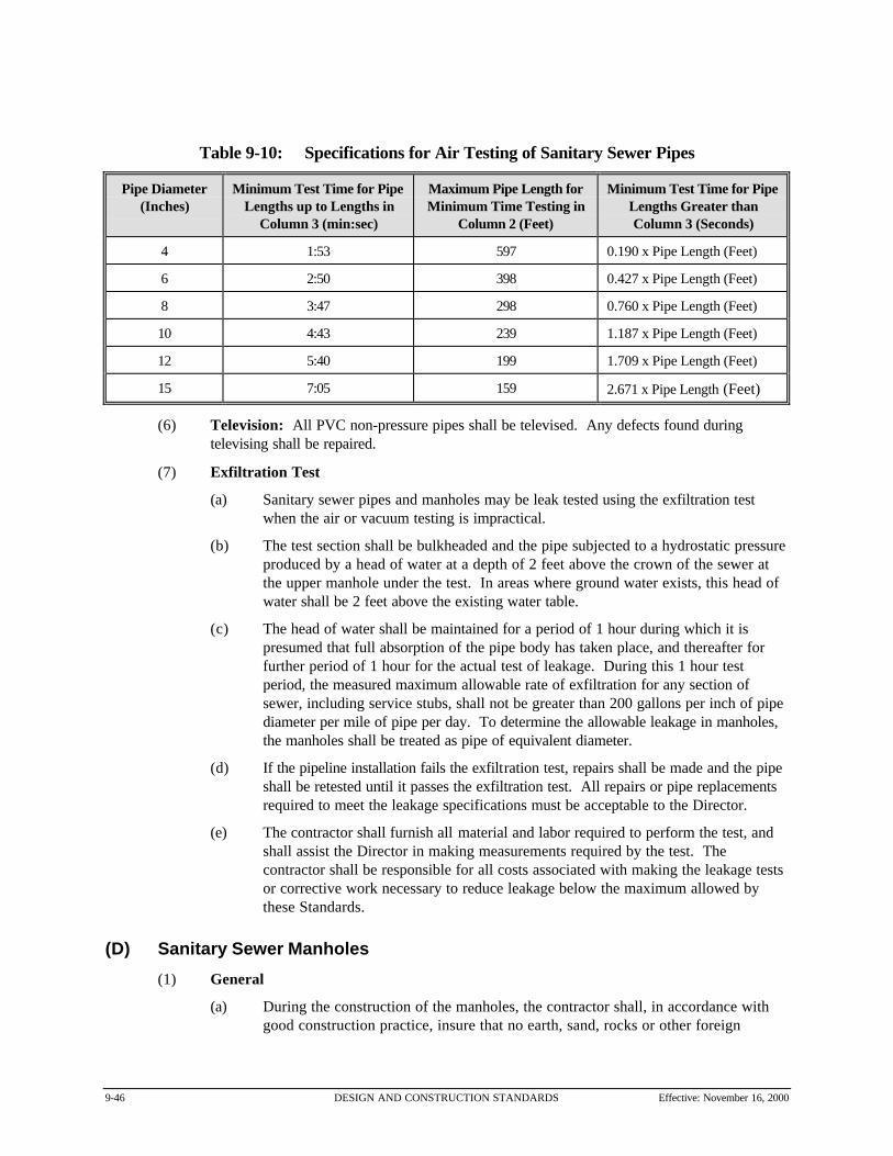
9-46 DESIGN AND CONSTRUCTION STANDARDS Effective: November 16, 2000
Table 9-10: Specifications for Air Testing of Sanitary Sewer Pipes
Pipe Diameter(Inches)
Minimum Test Time for PipeLengths up to Lengths in
Column 3 (min:sec)
Maximum Pipe Length forMinimum Time Testing in
Column 2 (Feet)
Minimum Test Time for PipeLengths Greater thanColumn 3 (Seconds)
4 1:53 597 0.190 x Pipe Length (Feet)
6 2:50 398 0.427 x Pipe Length (Feet)
8 3:47 298 0.760 x Pipe Length (Feet)
10 4:43 239 1.187 x Pipe Length (Feet)
12 5:40 199 1.709 x Pipe Length (Feet)
15 7:05 159 2.671 x Pipe Length (Feet)
(6) Television: All PVC non-pressure pipes shall be televised. Any defects found duringtelevising shall be repaired.
(7) Exfiltration Test
(a) Sanitary sewer pipes and manholes may be leak tested using the exfiltration testwhen the air or vacuum testing is impractical.
(b) The test section shall be bulkheaded and the pipe subjected to a hydrostatic pressureproduced by a head of water at a depth of 2 feet above the crown of the sewer atthe upper manhole under the test. In areas where ground water exists, this head ofwater shall be 2 feet above the existing water table.
(c) The head of water shall be maintained for a period of 1 hour during which it ispresumed that full absorption of the pipe body has taken place, and thereafter forfurther period of 1 hour for the actual test of leakage. During this 1 hour testperiod, the measured maximum allowable rate of exfiltration for any section ofsewer, including service stubs, shall not be greater than 200 gallons per inch of pipediameter per mile of pipe per day. To determine the allowable leakage in manholes,the manholes shall be treated as pipe of equivalent diameter.
(d) If the pipeline installation fails the exfiltration test, repairs shall be made and the pipeshall be retested until it passes the exfiltration test. All repairs or pipe replacementsrequired to meet the leakage specifications must be acceptable to the Director.
(e) The contractor shall furnish all material and labor required to perform the test, andshall assist the Director in making measurements required by the test. Thecontractor shall be responsible for all costs associated with making the leakage testsor corrective work necessary to reduce leakage below the maximum allowed bythese Standards.
(D) Sanitary Sewer Manholes
(1) General
(a) During the construction of the manholes, the contractor shall, in accordance withgood construction practice, insure that no earth, sand, rocks or other foreign

Effective: November 16, 2000 DESIGN AND CONSTRUCTION STANDARDS 9-47
material exists on the joint surfaces during assembly of the sections. The Directorshall check each manhole to determine whether the manhole fulfills the requirementsof the construction plans and these Standards.
(b) The Director shall visually check each manhole, both exterior and interior, for flaws,cracks, holes, or other inadequacies that might affect the operation or watertightintegrity of the manhole. Should any inadequacies be found, any repairs deemednecessary by the Director shall be made by the contractor.
(c) Exfiltration tests as specified above shall be performed on all sanitary sewermanholes.
(2) Vacuum Testing: When required by the Director, sanitary sewer manholes shall be vacuumtested with the following procedure:
(a) Each manhole shall be tested immediately after assembly and prior to backfilling.
(b) All lift holes shall be plugged with an approved non-shrink grout.
(c) No grout will be placed in the horizontal joints before testing.
(d) All pipes entering the manhole shall be plugged, taking care to securely brace theplugs from being drawn into the manhole.
(e) The test head shall be placed at the inside of the top of the cone section and the sealinflated in accordance with the manufacturer’s recommendation.
(f) A vacuum of 10 inches of mercury shall be drawn and the vacuum pump shut off. With the valves closed, the time shall be measured for the vacuum drop to 9 inches. The manhole shall pass if the time is greater than 60 seconds for one 48 inchdiameter manhole, 75 seconds for 60 inches, and 90 seconds for 72 inches.
(g) If the manhole fails the initial test, necessary repairs shall be made with a non-shrinkgrout while the vacuum is still being drawn. Retesting shall proceed until asatisfactory test is obtained.
9.17 Corrugated Metal Pipe
(A) General
(1) Scope: This section describes the furnishing and installation of corrugated metal pipe andappurtenances for drainage culverts in the pipe diameter size range of 12 to 54 inches.
(2) Quality Assurance: Manufacturer’s certificates of compliance and installationrecommendations shall be provided to the City inspector prior to construction. Installationrecommendations shall be followed during construction.
(B) Materials
(1) Corrugated Metal Pipe
(a) Pipe shall be fabricated from zinc-coated (galvanized) iron or steel sheetsconforming to AASHTO M-218 except as modified herein. The diameter or span byrise dimensions indicated on the drawings shall mean the nominal inside dimensionsof the conduit. The widths of the laps and depths or corrugations shall be asspecified in AASHTO M-36. The pipe shall have the following minimum gauge

9-48 DESIGN AND CONSTRUCTION STANDARDS Effective: November 16, 2000
(specified thickness) for the sizes shown in Table 9-11, “Corrugated Base MetalSpecifications,” of these Standards:
Table 9-11: Corrugated Base Metal Specifications
Diameter (Inches) Gauge Number Specified GalvanizedThickness (Inches)
Specified GalvanizedThickness (Inches)
21 and Smaller 16 0.064 0.0598
24 14 0.079 0.0747
30 - 54 12 0.109 0.1046
(2) Dimpled Coupling Bands: The dimpled coupling bands shall be the same thickness as thatused for the pipe and shall be at least 12 inches wide. The dimples shall conformsubstantially to the shape and depth of pipe corrugations and shall be in circumferential rows. Each row shall contain dimples so spaced as to effectively engage all corrugations of thepipe ends. All bands shall have at least two zinc coated bolts per connection, conforming toASTM A 307, grade A, electroplated in accordance with ASTM A 164, Type RS, not lessthan ½ inch in diameter. The bands shall have end connection angles, conforming to ASTMA 36, zinc-coated in accordance to ASTM A 153, not less than 2 inches by 2 inches by 3/16inch by 11 inches, adequately fastened to the band.
(3) Fittings (Including Flared End Sections) and Specials: Fittings and specials shall be ofthe same material, coating, and wall thickness, including the same structural qualities, as theadjoining pipe. Steel flared end sections shall be furnished complete with field-bolted toeplates.
(4) Repair of Damaged Spelter Coatings: Units such as tees, angles or bends on which thespelter coating has been burned by flame cutting and gas or arc welding, or otherwisedamaged in fabrication or shipping, shall be wire-brushed and painted with two coats ofHaltz-Rust HR-54-53 or equal conforming to Federal Specification and Standards, TT-P-641,or as otherwise approved by the Director. Culverts, pipes, fittings, specials, etc., on whichthe spelter coating has been bruised or broken either in the shop or in shipping, or that showsdefective workmanship, will be rejected.
(C) Execution
Installation of corrugated steel pipe is considered to be a flexible conduit and, therefore, special caremust be taken during the bedding and backfilling operations. Installation and backfilling operationsshall be in accordance with the recommended practices set forth in the “Handbook of Steel Drainageand Highway Construction Projects,” published by the American Iron and Steel Institute.
(1) Bedding
(a) All pipe shall be bedded with an approved granular bedding material. The pipe shallbe bedded true to line and grade with uniform and continuous support from a firmbase. Blocking shall not be used to bring the pipe to grade.
(b) The bedding material shall be placed evenly on both sides of the pipe to a point 12inches above the top of the pipe. Special care shall be taken to insure that all voidsare filled beneath the pipe haunch and that the bedding material is properly placed

Effective: November 16, 2000 DESIGN AND CONSTRUCTION STANDARDS 9-49
and compacted to provide lateral restraint. The trench sidewall shall be adequatelybraced, shored or sheeted as necessary to stabilize the trench walls. The trenchshall not be any wider than necessary for proper installation, and pipe jointing. Thebedding material shall be placed under haunches and around the pipe alternately in 6-inch layers on both sides of the pipe to permit thorough consolidation of the beddingmaterial. This material is placed alternately to keep it at the same elevation on bothsides of the pipe at all times.
(2) Backfilling: After the pipe has been properly installed and bedded, the remaining trenchexcavation shall be restored as set forth in Section 8-5-12, “Standards for Repairs andRestoration of Pavement or Sidewalks,” B.R.C. 1981. Pipe installed outside of public rights-of-way where no pavement is impacted may be backfilled in the following manner. Thebackfill shall be placed in 8 inch loose lifts and compacted to 90 percent Standard Proctordensity (AASHTO T-180) with mechanical hand tampers, for the first 2 feet. At least 4 feetof cover over the top of pipe shall be provided before the use of wheel-mounted mechanicaltampers (free drop hammer), hydraulic tampers, (Hydraulic ram hammers) or other heavytamping equipment will be permitted. Puddling or jetting will not be allowed.
(3) Removal of Trench Protection: Extreme care shall be taken in the removal of cribbing,shoring, sheeting, etc., so as not to disturb previously constructed foundation, bedding andinitial backfill. If it was necessary to place or drive sheeting or other trench protection belowthe top of the pipe, the sheeting, shoring, etc., shall be cut off at a point 1 foot above thepipe and the remaining material shall be left in place. Removal of this portion could seriouslyjeopardize the side support necessary for “flexible conduits” and create excessive lateral soilspressures and pipe deflections.
(4) Protection of Conduit During Construction: Maximum supporting strength in flexibleconduits does not develop until the fill consolidates. Therefore, excessive concentrated loadsor heavy equipment on top of or along side if the pipe shall be avoided.
9.18 Cured-in-Place Pipe (CIPP)
(A) General
(1) Scope: This section describes the reconstruction of pipelines and conduits by the installationof a resin-impregnated flexible tube that is inserted into the original conduit by use of ahydrostatic head.
(2) Quality Assurance: Manufacturer’s certificates of compliance and installationrecommendations shall be provided to the City inspector prior to construction. Installationrecommendations shall be followed during construction.
(B) Materials
(1) Resin-Impregnated Tube
(a) The tube shall meet the requirements of ASTM F1216 and shall have a uniformthickness that, when compressed at installation pressures, will equal the specifiednominal tube thickness, with a -5 percent manufacturing tolerance. The tube shallbe fabricated to a size that when installed will tightly fit the internal circumferenceand length of the original pipe. Allowance should be made for circumferentialstretching during insertion. The minimum length shall be that deemed necessary bythe contractor to effectively span the distance between respective access points

9-50 DESIGN AND CONSTRUCTION STANDARDS Effective: November 16, 2000
unless otherwise specified. The contractor shall verify the lengths and diameters inthe field before fabricating the tube. Individual insertion runs can be made over oneor more manhole sections as determined in the field by the contractor. Themaximum allowed insertion run is 1,200 feet. Intermediate manholes will bereopened as directed by the Director.
(b) The outside layer of the tube (before insertion) shall be translucent plastic coatedwith a flexible material that clearly allows inspection of the resin impregnation (wet-out) procedure. The translucent plastic coating on the tube will allow visual proofthat the resin has wet-out the entire tube and that there are no dry areas. A vacuumshall be used to ensure the resin fills all dry areas. The plastic coating shall not besubject to delamination after curing of the CIPP.
(c) The tube shall be homogenous across the entire wall thickness containing nointermediate or encapsulated elastomeric layers. No materials will be allowed in thetube that is subject to delamination of the cured CIPP.
(d) The wall color of the interior pipe surface of the CIPP after installation shall bewhite or light brown so that a clear detail examination with closed circuit televisioninspection equipment can be made.
(2) Resin: The resin system shall meet the requirements of ASTM F1216.
(3) Structural Requirements
(a) The CIPP wall thickness will be measured in accordance with the applicablesections of ASTM Test Method D2122. Sufficient readings, at least eight, will bemade to ensure that the minimum thickness has been determined. A cylindrical anviltubing micrometer accurate to +0.02mm (+0.001 in) will be used. The minimumwall thickness at any cross section shall meet or exceed those shown on theproposal forms and the approved plans, with the allowable minus five (-5) percenttolerance. The wall thickness tests will be performed by a Certified IndependentLaboratory, approved by the Director. All costs, for testing, shall be borne by thecontractor.
(b) The layers of the CIPP shall be uniformly bonded. It shall not be possible toseparate any two layers with a probe or point of a knife blade so that the layersseparate cleanly of the probe or knife blade moves freely between the layers, norshall separation of any layers occur during testing performed under the requirementsof this specification.
(c) The cured pipe material (CIPP) shall conform to the minimum structural standards,as follows:
(i) Flexural Stress (ASTM D-790) 4,500 psi
(ii) Modulus of Elasticity (ASTM D-790) 250,000 psi
(C) Execution
(1) Cleaning
(a) The contractor shall be required to remove all internal debris from the sewer line byuse of water jet equipment prior to inserting the CIPP tube. The cleaning operation

Effective: November 16, 2000 DESIGN AND CONSTRUCTION STANDARDS 9-51
shall remove any and all debris so that each joint of pipe can be thoroughly inspectedand successfully reconstructed.
(b) All sludge, dirt, sand, rocks, grease and other solid or semi-solid material resultingfrom the cleaning operation shall be removed at the downstream manhole of thesection being cleaned. Passing material from one manhole to another will not bepermitted.
(c) All such debris resulting from the cleaning operations shall be removed from the siteand disposed of in the proper manner. The contractor shall bear all costs associatedwith testing of debris and proper dumping. Dumping of the debris shall be inaccordance with all local, state, and federal regulations.
(d) All debris shall be removed from the downstream manhole and the site no less oftenthan at the end of each workday. The contractor shall leave no debris unattended atthe site. Under no circumstances will the contractor be allowed to accumulatedebris beyond the stated time. In the event the contractor has not removed thedebris generated by the cleaning operation, the contractor will not be allowed toproceed with the work until the debris is properly removed.
(e) During all sewer cleaning operations, satisfactory precautions shall be taken toprotect the sewer lines from damage that might occur by improper use of cleaningequipment. Precautions shall be taken to ensure that the cleaning operation will notcause any damage or flooding to public or private property being served by thesection of sewer line being cleaned. The contractor shall bear all costs associatedwith any flooding or damage to basements or structures.
(2) Bypassing Sewage: The contractor shall provide for the flow of sewage around thesection(s) of pipe designated for reconstruction. The bypass shall be made by plugging thesewer line at an existing upstream manhole or adjacent system. The pump and bypass linesshall be of adequate capacity and size to handle the flow. Bypassing includes any main linesand service lines, street gutters or open excavations. Any spills that occur must beimmediately cleaned and the affected area disinfected.
(3) Inspection of Pipelines: Inspections of pipelines shall be performed by trained personnelexperienced in locating breaks, obstacles and service connections by closed circuit television. The inspection of pipelines is also to determine active service connections and the addressesthat they serve. The interior of the pipe shall be carefully inspected to determine the locationof any conditions that may prevent proper installation of the CIPP into the pipeline and it shallbe noted so these conditions can be corrected. A videotape and suitable log shall besubmitted to the Director, and shall be kept for later reference.
(4) Line Obstructions: It shall be the responsibility of the contractor to clear the line ofobstructions such as solids and roots that will prevent the insertion of the CIPP. If pre-installation inspection reveals an obstruction such as a protruding service connection,dropped joint, or a collapse that will prevent the inversion process, and it cannot be removedby conventional sewer cleaning equipment, then the contractor shall repair the excavation touncover and remove or repair the obstruction. Such excavation shall be approved in writingby the Director prior to the commencement of the work.
(5) CIPP Installation
(a) CIPP installation shall be in accordance with ASTM F1216, Section 7, with theadditional following requirements. The resin shall be cured by circulating hot water

9-52 DESIGN AND CONSTRUCTION STANDARDS Effective: November 16, 2000
within the tube. After curing, the finished pipe (CIPP) shall be continuous and tightfitting.
(b) The contractor, and the Director, shall designate a location where the tube will beimpregnated with resin prior to installation, in order that an inspection can be madeto determine proper materials and procedures. A resin and catalyst systemcompatible with the requirements of this method shall be used.
(c) The heat source shall be fitted with suitable monitors to gauge the temperature of theincoming and outgoing heat supply. Another such gauge shall be placed at theremote manhole to determine the temperature at that location during the cure. If airpressure and steam are used with styrene based resins, the compressed atmosphereshall be monitored with a safety gas detector to ensure that it does not reach theexplosive limit.
(d) The finished CIPP shall be continuous over the entire length of an insertion runbetween two manholes and be free, as commercially practicable, from visual defectssuch as foreign inclusions, dry spots, pinholes, and delamination. It shall also meetthe leakage/pressure test requirements specified below (water tightness).
(e) Before the insertion process begins, the minimum pressure required to hold the tubetight against the existing conduit and the maximum allowable pressure so as not todamage the tube shall be provided by the tube manufacturer, and it will be thecontractor’s responsibility to obtain and submit this information to the Director. Once the insertion has started, the pressure shall be maintained between theminimum and maximum pressures until the operation has been completed. If airpressure is used for inversion, the equipment shall be fitted with a pressure gaugeaccurate to 0.01 psi. Should the pressure deviate from within the range of minimumand maximum pressures, the installed tube will be rejected and the contractor willremove and dispose of the tube, at their expense.
(f) Before the curing process begins, the pressure required to hold the flexible tube tightagainst the host pipe shall be provided by the tube manufacturer and submitted to theDirector prior to any inversion process. Once the cure has started and dimpling forlaterals is completed, the required pressure shall be maintained until the cure iscomplete. Should the pressure deviate more than 1 psi (2.3 feet of water) from therequired pressure during the critical curing period, the tube will be rejected and thecontractor will be responsible for its removal and disposal and replacement with newCIPP at, at their expense. A complete log of the pressures shall be maintained onsite and shall be offered to the Director after each inversion.
(6) Sealing at Manholes: If the CIPP fails to make a tight seal against the original pipe at itstermination point(s), the space between the pipes shall be sealed by filling with a resinmixture compatible with the cured-in-place pipe and as recommended by the manufacturer.
(7) Service Connections
(a) After the curing of the CIPP is completed, the contractor shall restore the existingactive service connections and branch connections. It is the intent of theseStandards that active service and branch connections be reopened withoutexcavation, and in the case of non-man entry pipes, from the interior of the pipelineutilizing a remotely controlled cutting device, monitored by a closed circuit televisioncamera, that re-establishes them to not less than 95 percent capacity, whileconforming to the shape of the existing opening.

Effective: November 16, 2000 DESIGN AND CONSTRUCTION STANDARDS 9-53
(b) The contractor shall verify the possession of at least two complete cutting devices ingood working order before each insertion.
(c) If excavations for the purpose of re-opening connections are required, thecontractor will be responsible for all costs and liability associated with suchexcavation and restoration work.
(d) No service connection shall remain out of service for more than 24 hours at a timeunless the contractor has provided temporary facilities or other appropriateaccommodations for the affected service.
(8) Testing: CIPP samples shall be prepared and tested in accordance with ASTM F1216,Section 8.1, using both methods 8.1.1 and 8.1.2. The test will be performed by a CertifiedIndependent Laboratory, approved by the City. Tests results shall be submitted to theDirector. Costs of the tests are considered to be incidental to the project.
(9) Visual Inspection: Visual inspection of the CIPP shall be in accordance with ASTM F1216,Section 8.4. The contractor shall furnish the Director with a color video tape that containsboth the before and after conditions, and the restored service and branch connections withthe addresses each connection serves.
(10) Exfiltration Tests: In the absence of ground water, and if so ordered by the Director, anexfiltration test shall be performed. Leakage testing of the CIPP shall be accomplished aftercuring when the CIPP has cooled down to ambient temperatures and while under a positivehead and before any service connections are reinstated. This test is limited to pipe diametersof 36 inches or less. The allowable water exfiltration for any length of pipe betweentermination points shall not exceed 50 gallons per inch of internal pipe diameter per mile perday, providing all trapped air has been purged from the line. During exfiltration testing, themaximum internal pipe pressure at the lowest point shall not exceed 10 feet of water or 4.3psi and the water level inside the inversion standpipe shall be 2 feet higher than the top of thepipe being tested or 2 feet higher than the groundwater level, whichever is greater. Theleakage quantity shall be gauged by the water level in the temporary standpipe placed in theupstream plug. The test shall be conducted for 1 hour. CIPP products where the pipe wallis cured while not in direct contact with the pressurizing fluid (e.g., a removable bladder)must be tested by an alternative method approved by the Director.
9.19 Telecommunication or Cable System StandardsThe installation and construction of telecommunication or cable systems shall comply with the requirementsas set forth in Chapter 11-6-5, “Boulder Cable Code,” B.R.C. 1981 and these Standards.
(A) General
(1) Applicable National Standards: All telecommunications and cable system construction shallconform to the requirements of the following standards:
(a) American National Standards Institute, Inc. (ANSI), Electronic IndustriesAssociation (EIA), and Telecommunications Institute of America (TIA) Standards:EIA/TIA Standards Proposal No. 2840-A, Proposed Revision of EIA/TIA-568 (ifapproved to be published as EIA/TIA-568-A), EIA/TIA-569 Commercial BuildingStandard for Telecommunications Pathways and Spaces, and TIA/EIA-607Commercial Building Grounding and Bonding Requirements forTelecommunications.

9-54 DESIGN AND CONSTRUCTION STANDARDS Effective: November 16, 2000
(b) National Electrical Safety Code (NESC) C2-1993, published by the Institute ofElectrical and Electronics Engineers (IEEE), Inc.
(c) National Electrical Code (NEC), published by the National Fire ProtectionAssociation (NFPA).
(d) Federal Communications Commission.
(e) Colorado Public Utilities Commission.
(f) Williams-Steiger Occupational Safety and Health Act (OSHA).
(2) Construction Plans Required: Detailed construction plans, as outlined in Chapter 1,“General Requirements,” of these Standards, showing the specific underground and/or aerialcable routing and associated conduit, manhole and/or pole locations and specifications, shallbe submitted to the Director office for review and approval.
(3) Protection of Systems: All systems shall be protected from washouts, floods, unstable soil,landslides, or other hazards that may cause the facility to move or fail.
(B) Underground Facilities
(1) Cable Protection
(a) All buried telecommunications cable, shall be installed in conduit, PVC Schedule 40or equivalent. Cable placement by means of direct plow-in will not be allowed withinthe City’s rights-of-way.
(b) Major conduit duct banks (more than 4 conduits) and those comprising a portion ofthe City’s telecommunications conduit backbone infrastructure shall be encased inconcrete with a minimum strength of 2000 psi. When encased in concrete, conduitmay be PVC Type EB, DB or equivalent. The concrete encasement shall have aminimum thickness of 4 inches around the entire conduit or duct bank.
(c) Multiple duct systems shall have spacers installed at intervals to allow the concretemix encasement throughout the entire duct structure.
(d) Conduit placed by directional bore method will be allowed subject to approval by theDirector.
(2) Depth of Cover: The minimum depth of cover over the conduit shall be 30 inches.
(3) Trench Specifications - Roadway and Other Paved Surfaces
(a) All trenches shall be open cut unless otherwise permitted by the City.
(b) Trenches shall be have a minimum width of 10 inches.
(c) Trench backfill and surface restoration shall comply with the standards as set forthin Section 8-5-12, “Standards for Repairs and Restoration of Pavement andSidewalks,” B.R.C. 1981.
(4) Trench Specifications - Landscaped Areas
(a) All trenches shall be open cut unless otherwise permitted by the City.
(b) Trenches shall be have a minimum width of 10 inches.
(c) Trenches shall be backfilled and compacted to at least 90 percent of maximumdensity at optimum moisture content as determined by ASTM D698.

Effective: November 16, 2000 DESIGN AND CONSTRUCTION STANDARDS 9-55
(d) The City shall be contacted if there is any question whether or not the proposedwork will cause any damage to tress, shrubs or other landscaping or if constructionis within 5 feet of a tree.
(5) Alternative Installation Methods: Boring methods may be allowed by the Director if theDirector finds that these methods are advantageous to the City or if open trench methods areimpractical.
(6) Joint Use Trench Requirements
(a) Joint trenching operations require advanced planning and coordination with theutilities involved.
(b) Vertical and horizontal separations between telecommunications or cable systemsand other facilities shall be maintained as required by NESC Section 32,Underground Conduit Systems. Conduit systems for telecommunications and cablesystems shall be separated from conduit systems for power supply systems by:
(i) 3 inches of concrete,
(ii) 4 inches of masonry, or
(iii) 12 inches of well-tamped earth,
(7) Warning Tape: A cable warning tape shall be placed 12 to 18 inches above the conduit inthe trench.
(8) Manholes
(a) All cavities required for cable pulling purposes shall be constructed as load bearingmanholes or handholes. Handholes shall not be placed in any traveled lane, roadshoulders, sidewalk, multi-use path, or bike lane.
(b) Manholes or handholes shall be placed at maximum 1200 feet intervals. In no caseshall conduit bend radius exceed 180 degrees between manholes. Manholes shall beinstalled at each street intersection at a minimum. Manholes shall be rectangular: 6feet wide by 7 feet long by 4 feet deep; or circular 4 feet diameter with a nominaldepth of 4 feet minimum.
(c) Manholes or handholes shall be installed flush or ¼” below the surrounding grade.
(C) Aboveground Facilities
(1) Facility Protection: All aboveground facilities shall be protected from accidental damage byvehicular traffic impacts or similar causes either by being located a safe distance away fromtraffic or by structural barricades.
(2) Obstruction to Traffic Prohibited: All aboveground facilities shall be located so as not tocause unnecessary obstruction to pedestrian and vehicular traffic.
(3) Clearances: All aboveground telecommunications facility construction shall conform withthe minimum clearances as specified in Section 23 of the NESC.
(a) Cables shall maintain the following minimum clearances between any adjacent orcrossing power cables under all conditions of cable loading:
(i) Horizontal clearances shall be at least 5 feet from power cables at a potentialof up to 129 kV, and at least 5 feet plus 0.4 inches per kV over 129 kVfrom power cables exceeding a potential of 129 kV.

9-56 DESIGN AND CONSTRUCTION STANDARDS Effective: November 16, 2000
(ii) Vertical clearances shall be at least 4 feet from power cables at a potentialof up to 750 V, at least 6 feet from power cables at a potential of 750 V to22 kV, at least 6 feet plus 0.4 inches per kV over 22 kV from power cablesat a potential between 22 kV and 470 kV. Vertical clearances shall complywith NESC Rule 233C3 for minimum clearance from cables at a potentialgreater than 470 kV.
(b) Cables, poles, and stubs shall maintain the following minimum clearances frompower conductors, power poles and other objects:
(i) Poles shall have a minimum clearance of 4 feet from fire hydrants, signalpedestals, and call boxes.
(ii) Cables shall have a minimum horizontal clearance from power poles in nowind conditions.
(iii) Poles and stubs shall have a minimum horizontal clearance of 5 feet in nowind condition from power wires up to 50 kV.
(c) Poles shall have a minimum separation of at least 2 feet from the street side of thecurb to the nearest part of the pole and shall be located a sufficient distance from thestreet side of the curb to avoid contact with ordinary vehicles using the road.
(d) Poles shall have at least 12 feet horizontal clearance from the nearest rail to thenearest part of the pole.
(e) Cables shall have at least 2 feet vertical clearance from Police and Fire Alarmfacilities.
(f) Cables shall have at least 3 feet clearance in all directions from signs, chimneys,tanks, and other installations.
(g) Cables shall maintain the following minimum vertical clearances as measured fromthe lowest point of the cable when crossing the following objects:
(i) Roads, Streets, and all areas subject to truck traffic: 18 feet.
(ii) Alleys, Driveways, and Parking Lots: 18 feet.
(iii) Railroad tracks: 28 feet.
(iv) Roofs, not accessible: 4 feet.
(v) Spaces and Ways, accessible to pedestrians only: 12 feet.
(vi) Roofs, accessible to vehicular traffic, but not trucks: 12 feet.
(h) Cables shall maintain a minimum vertical clearances of 16 feet as measured from thelowest point of the cable when running alongside but not overhanging roads, streets,or alleys.
(i) A minimum vertical clearance of 40 inches shall be maintained betweentelecommunications cables and power cables at the attachment points on joint usepoles.
9.20 Electric Power Facility StandardsThe following standards shall apply to all electric power related facilities constructed within the City’s publicrights-of-way or easements.
Effective: November 16, 2000 DESIGN AND CONSTRUCTION STANDARDS 9-57
(A) General
(1) Undergrounding Required: All electric power facilities constructed in the City’s publicrights-of-way or easements shall be underground unless otherwise permitted by franchise orthe Director.
(2) National Standards: All electric power facility construction shall conform to therequirements of the following standards:
(a) 1993 National Electrical Safety Code (NESC) C2-1993, published by the Institute ofElectrical and Electronics Engineers (IEEE), Inc.
(b) National Electrical Code (NEC), published by the National Fire ProtectionAssociation (NFPA).
(c) Colorado Public Utilities Commission.
(d) Williams-Steiger Occupational Safety and Health Act (OSHA).
(3) Construction Plans Required: Detailed construction plans, as outlined in Chapter 1,“General Requirements,” of these Standards, showing the specific underground and/or aerialcable routing and associated conduit, manhole and/or pole locations and specifications, shallbe submitted to the Director for review and approval.
(4) Protection of Facilities: All facilities must be protected from washouts, floods, unstablesoil, landslides, or other hazards that may cause the facility to move or fail.
(B) Underground Facilities
(1) Underground Cable Protection
(a) All primary circuits (greater than 600 volts) located under concrete road surfaces,where circuit density is high, and in all arterial roads shall be installed in conduit, 4inch minimum diameter, PVC Type EB, DB or equivalent. All conduit joints shall besolvent welded. The conduit shall be encased in concrete with a minimum strengthof 2000 psi and have a minimum thickness of 4 inches around the entire conduit orduct bank.
(b) All secondary circuits (600 volts or less) supplying services larger than 800 amperesshall be installed in conduit, 2-inch minimum diameter, PVC Type EB, DB orequivalent. All conduit joints shall be solvent welded. The conduit shall be encasedin concrete with a minimum strength of 2000 psi and have a minimum thickness of4 inches around the entire conduit or duct bank.
(c) Multiple duct bank systems shall have spacers installed at intervals to allow theconcrete mix encasement throughout the entire duct structure.
(2) Depth of Cover
(a) The minimum depth of cover over primary circuits (greater than 600 volts) shall be42 inches.
(b) The minimum depth of cover over secondary circuits shall be 30 inches (600 voltsor less).
(c) The minimum depth of cover over circuits for street lighting and signals shall be 18inches.
9-58 DESIGN AND CONSTRUCTION STANDARDS Effective: November 16, 2000
(3) Trench Specifications - Roadways and Other Paved Surfaces
(a) All trenches shall be open cut unless otherwise permitted by the Director.
(b) Trenches shall be have a minimum width of 10 inches.
(c) Trench backfill and surface restoration shall comply with the standards as set forthin Section 8-5-12, “Standards for Repairs and Restoration of Pavement andSidewalks,” B.R.C. 1981.
(4) Trench Specifications - Landscaped Areas
(a) All trenches shall be open cut unless otherwise permitted by the Director.
(b) Trenches shall be have a minimum width of 10 inches.
(c) Trenches shall be backfilled and compacted to at least 90 percent of maximumdensity at optimum moisture content as determined by ASTM D698.
(d) The City shall be contacted if there is any question whether or not the proposedwork will cause any damage to trees, shrubs or other landscaping or if constructionis within 5 feet of a tree.
(5) Alternative Installation Methods: Boring methods may be allowed by the Director if theDirector finds that these methods are advantageous to the City or if open trench methods areimpractical.
(6) Joint Use Trench Requirements
(a) Joint trenching operations require advanced planning and coordination with theutilities involved.
(b) Vertical and horizontal separations between electric power facilities and otherfacilities shall be maintained as required by the NESC section 32 UndergroundConduit Systems.
(7) Warning Tape: A cable warning tape shall be placed 12 to 18 inches above the conduit orcable in the trench.
(8) Manholes: All cavities required for cable pulling purposes shall be constructed as loadbearing manholes or handholes. Handholes shall not be placed in any traveled lane includingroad shoulders, sidewalks, multi-use paths, or bike lanes.
(C) Aboveground Facilities
(1) General
(a) All aboveground facilities shall be protected from accidental damage by vehiculartraffic impacts or similar causes either by being located a safe distance away fromtraffic or by structural barricades.
(b) All aboveground facilities shall be located so as not to cause unnecessary obstructionto pedestrian and vehicular traffic.

Effective: November 16, 2000 DESIGN AND CONSTRUCTION STANDARDS 9-59
(2) Clearances: The minimum overhead transverse clearance shall conform to NationalElectrical Safety Code Standards, but shall not be less than 18 feet measured from thehighest point of the road prism to the bottom of the cable.
9.21 Gas Distribution Facility StandardsThe following standards shall apply to all gas distribution related facilities constructed within the City’s publicrights-of-way or easements.
(A) General
(1) Undergrounding Required: All gas distribution facilities constructed in the City’s publicrights-of-way or easements shall be underground unless otherwise permitted by franchise orthe Director.
(2) National Standards: All gas distribution facility construction shall conform to therequirements of the following standards:
(a) Minimum Federal Safety Standards for Natural Gas Pipelines in the Code of Federalregulations 49 Part 192.
(b) Colorado Public Utilities Commission.
(c) Williams-Steiger Occupational Safety and Health Act (OSHA).
(3) Construction Plans Required: Detailed construction plans, as outlined in Chapter 1,“General Requirements,” of these Standards, showing the specific gas distribution line andappurtenances locations and specifications, shall be submitted to the Director for review andapproval.
(4) Protection of Facilities: All facilities must be protected from washouts, floods, unstablesoil, landslides, or other hazards that may cause the facility to move or fail.
(B) Underground Facilities
(1) Materials
(a) Steel or plastic material shall be used for the gas distribution pipe.
(b) All plastic pipe must be installed below ground level.
(2) Depth of Cover
(a) Depth of cover shall be measured from the final grade to the top of the pipe.
(b) Minimum depth of cover for shall be 36 inches for transmission lines and 30 inchesfor distribution lines.
(c) Minimum depth of cover for service lines shall be 24 inches.
(d) Transmission and distribution lines installed under streams and ditches must haveminimum cover of 48 inches.
(3) Trench Specifications - Roadways and Other Paved Surfaces
(a) All trenches shall be open cut unless otherwise permitted by the Director.
(b) Trenches shall have a minimum width of 10 inches.
9-60 DESIGN AND CONSTRUCTION STANDARDS Effective: November 16, 2000
(c) Trench backfill and surface restoration shall comply with the standards as set forthin Section 8-5-12, “Standards for Repairs and Restoration of Pavement andSidewalks,” B.R.C. 1981.
(4) Trench Specifications - Landscaped Areas
(a) All trenches shall be open cut unless otherwise permitted by the Director.
(b) Trenches shall be have a minimum width of 10 inches.
(c) Trenches shall be backfilled and compacted to at least 90 percent of maximumdensity at optimum moisture content as determined by ASTM D698.
(d) The City shall be contacted if there is any question whether or not the proposedwork will cause any damage to tress, shrubs or other landscaping or if constructionis within 5 feet of a tree.
(5) Alternative Installation Methods: Boring methods may be allowed by the Director if theDirector finds that these methods are advantageous to the City or if open trench methods areimpractical.
(6) Joint Use Trench Requirements
(a) Joint trenching operations require advanced planning and coordination with theutilities involved.
(b) Vertical and horizontal separations between gas distribution facilities and otherfacilities shall be 6 inches minimum.
(7) Warning Tape: A cable warning tape shall be placed 12 to 18 inches above the conduit inthe trench.
(8) Components
(a) Transmission line valves shall be installed in boxes or be otherwise readilyaccessible.
(b) Transmission line pressure relief and pressure limiting devices shall be installed inunderground vaults, unless aboveground installation is permitted by the Director.
(c) All service lines shall be equipped with shutoff valves.
(d) An electrically conductive tracer wire shall be installed with all plastic and non-conductive pipes.
(9) Casing Pipe: Gas pipe shall be installed in casings under all highways. Casing pipe shall besteel pipe with a wall thickness of 1/4 inch minimum extending at least 5 feet beyond thelimits of any highway improvements.
(10) Corrosion Protection
(a) All pipes susceptible to corrosion shall be cathodically protected and have aprotective coating.
(b) All corrosion susceptible pipes must also be electrically isolated from other metallicstructures.

Effective: November 16, 2000 DESIGN AND CONSTRUCTION STANDARDS 9-61
(C) Testing Requirements
All newly constructed pipes shall be tested prior to placing the line in service. No pipe shall be placedin service, or returned to service, with leaks or without adequate corrosion protection.
(1) Pressure Testing: All pipes shall be pressure tested for leakage as described in CFR 49 part192. In order to establish the maximum allowable operating pressure (MAOP), pipes shall betested at 1-1/2 times the MAOP.
(2) Corrosion Control Testing: Corrosion control devices shall be tested whenever the pipe isexposed for maintenance or repair. Additionally, all corrosion control devices must be testedat least once each calendar year.
(3) Records Retention: Records of the testing shall be maintained for the life of the pipe.
(D) Aboveground Facilities
(1) Facility Protection: All aboveground facilities shall be protected from accidental damage byvehicular traffic impacts or similar causes either by being located a safe distance away fromtraffic or by structural barricades.
(2) Traffic Obstruction Prohibited: All aboveground facilities shall be located so as not tocause unnecessary obstruction to pedestrian and vehicular traffic.