DESIGN & CONSTRUCTION OF VOICE CONTROLLED ROBOT
71
DESIGN & CONSTRUCTION OF VOICE CONTROLLED ROBOT A Project and Thesis proposed in some achievement of the Requirements for the Award of Degree of Bachelor of Science in Electrical and Electronic Engineering Submitted By Md.Sazzad Hossen ID:143-33-2107 Md.Mezbahul Islam ID: 143-33-2234 Supervised By PROF.DR. M. SHAMSUL ALAM Professor and Dean Faculty of Engineering Daffodil International University DEPARTMENT OF ELECTRICAL AND ELECTRONIC ENGINEERING FACULTY OF ENGINEERING DAFFODIL INTERNATIONAL UNIVERSITY
Transcript of DESIGN & CONSTRUCTION OF VOICE CONTROLLED ROBOT

DESIGN & CONSTRUCTION OF VOICE
CONTROLLED ROBOT
A Project and Thesis proposed in some achievement of the
Requirements for the Award of Degree of
Bachelor of Science in Electrical and Electronic Engineering
Submitted By
Md.Sazzad Hossen
ID:143-33-2107
Md.Mezbahul Islam ID: 143-33-2234
Supervised By
PROF.DR. M. SHAMSUL ALAM Professor and Dean
Faculty of Engineering
Daffodil International University
DEPARTMENT OF ELECTRICAL AND ELECTRONIC
ENGINEERING
FACULTY OF ENGINEERING
DAFFODIL INTERNATIONAL UNIVERSITY
Page | ii ©Daffodil International University
TO
OUR BELOVED PARENTS
&
HONOURABLE SUPERVISER

Page | iii ©Daffodil International University
Declaration
We hereby declare that this thesis paper is based on the results found by our research work and
other researchers are mentioned by reference. This thesis has not been submitted before for any
degree.
_______________ _______________
Md Mezbahul Islam Md Sazzad Hossen
December 2018
____________ Date

Page | iv ©Daffodil International University
Certificate of Approval
This is to certify that this project and thesis entitled “Construction of Voice Control Robot System”
is committed under the following students by my direct review and this action has been rowed out
under them in the Department of Electrical and Electronic Engineering below the Faculty of
Engineering of Daffodil International University in some fruition of the requirements for the
degree of Bachelor of Science in Electrical and Electronic Engineering. The presentation which
was held on December 2018.
Countersigned
_______________________
Prof. Dr. M. Shamsul Alam
Professor and Dean
Department of Electrical and Electronic Engineering
Faculty of Engineering
Daffodil International University

Page | v ©Daffodil International University
INDEX
CONTENTS PAGE
NO
Certification…………………………………………………….. III
LIST OF FIGURES………………………………………………... XII-
XIV
LIST OF TABLES…………………………………………………….. XV
ABBREVIATIONS…………………………………………………... X-XII
ACKNOWLEDGEMENT……………………………………………... 1
ABSTRACT…………………………………………………………...... 2
CHAPTER
1: INTRODUCTION…………………… (1-3)
1.1 INTRODUCTION…………………………….. 03
1.2 AIM OF THE PROJECT………………………. 04
1.3 SCOPES……………………………………….. 04
1.4 METHODOLOGY……………………………. 05
1.5 ORGANIZATION OF THE REPORT……….. 05
CHAPTER 2 SYSTEM REVIEW……………………. (4-8)
2.1 INTRODUCTION……………………………... 04
2.2 BLOCK DIAGRAM…………………………… 04
2.3 MICROPROCESSORS VS…………………….
MICROCONTROLLER.
05

Page | vi ©Daffodil International University
2.4 BASIC DESCRIPTION OF CONTROLLER.. UNIT 05
2.5 DECRIPTION OF MICROCONTROLLER….. ATMEGA 328 05
2.6 DESCRIPTION OF BLOCK DIAGRAM……… 06
2.7 CIRCUIT DIAGRAM………………………….. 06
2.8 WORKING PROCESS OF OUR CIRCUIT…… 07
2.9 LIST OF COMPONENT USED IN CIRCUIT… 07
2.10 CONCLUSION………………………………… 08
CHAPTER
3: COMPONENT DESCRIPTION … (9-27)
3.1 INTRODUCTION……………………………... 09
3.2 DESCRIPTION2 BLUETOOTH MODULE…… 09
3.2.1 FEATURES OF BLUETOOTH MODULE HC-05 10
3.2.2 PIN DESCRIPTION OF HC-05……………… 14
3.2.3 SUMMARY…………………………………… 15
3.3 BASIC DESCRIPTION OF ANDROID…. APPLICATION 15
3.3.1 VOICE APPLICATION……………………….. 16
3.4 BASIC DESCRIPTION OF CONTROLLER. UNIT 16
3.4.1 TECHNICAL SPECIFICATION OF ARDUINO UNO 17
3.4.2 DESCRIPTION OF MICROCONTROLLER ATMEGA328 18
3.4.3 BLOCK DIAGRAM MICROCONTROLLER ATMEGA328 19

Page | vii ©Daffodil International University
3.4.4 PIN CONFIGURATIONS OF MICROCONTROLLER
ATMEGA 328
19
3.4.5 PIN DESCRIPTION ………………………… 20
3.5 L298N MOTOR DRIVER……………………. 21
3.5.1 L298N CONNECTIONS……………………… 23
3.5.2 VOLTAGE SPECIFICATION………………… 23
3.6 DESCRIPTION OF LCD DISPLAY16x2…….. 24
3.6.1 SHAPES AND SIZES………………………… 24
3.6.2 PIN DESCRIPTION…………………………… 25
3.6.3 CONTROL LINES…………………………….. 25
3.6.4 INITIALLIZATION BY INSTRUCTIONS…... 25
3.7 DC MOTOR…………………………………….. 25
3.7.1 TYPES OF DC MOTOR……………………….. 25
3.7.2 WORKING AND OPERATING PRINCIPLE OF DC
MOTORS
25
3.8 BASIC ARDUINO SOFTWARE……………… 25
3.8.1 FEATURES OF ARDUINO SOFTWARE……. 25
3.9 WIRES…………………………………………. 26
3.10 POWER SUPPLY 12 VOLT………………….. 26
3.10.1 SPECIFICATIONS……………………………… 26
3.11 COST ANALYSIS……………………………… 27
3.11.1 COST SHEET…………………………………… 27

Page | viii ©Daffodil International University
3.12 CONCLUTION…………………………………. 27
Chapter 4: SOFTWARE ANALYSIS ……………………
(28-30)
4.1 INTRODUCTION……………………………. 28
4.2 DESCRIPTION OF OUR SOFTWARE……… 28
4.3 FLOW CHART AND DIAGRAM……………. 29
4.4 CONCLUTION………………………………... 30
Chapter 5: SCHEMATIC REPRESENTATION…………… (31-36)
5.1 INTRODUCTION……………………………… 31
5.2 SCHEMATIC DIAGRAM……………………… 31
5.2.1 CRYSTAL OSCILIATOR ……………………... 32
5.2.2 RESISTOR……………………………………… 32
5.2.3 SWITCHES……………………………………… 33
5.2.4 MOTORS………………………………………… 33
5.2.5 LCD………………………………………………… 33
5.2.6 MICROCONTROLLER…………………………… 34
5.2.7 DRIVER MODULE………………………………... 34
5.2.8 CHARGED BATTARIES………………………… 34
5.2.9 REGULATION……………………………………. 35
Page | ix ©Daffodil International University
5.2.10 CONNECTING WIRES…………………………… 35
5.3 CONCLUTION……………………………………. 36
Chapter 6: RESULTS AND DISCUSSION…………… (37-41)
6.1 INTRODUCTION ………………………………… 37
6.2 ASSEMBLING THE BOARD…………………….. 37
6.2.1 ASSEMBLING THE PROCESS…………………… 38
6.2.2 COMPLETION OF ASSEMBLING PROCESS…... 39
6.3 ANDROID APPLICATION……………………….. 39
6.3.1 BLUETOOTH SPP TEST…………………………... 40
6.3.2 BLUETOOTH AMR (ANDROID MEETS ROBOT) 40
6.4 ROBOTS WORKING MECHANISM……………. 41
6.5 TESTING…………………………………………… 41
6.6 CONCLUSION…………………………………….. 41
CHAPTER-7 CONCLUSION………………………….
(42-44)
7.1 APPLICATIONS………………………………….. 42
7.1.1 HOME AUTOMATION…………………………….. 42
7.1.2 WHEEL CHAIRS………………………………..... 43
7.1.3 SURVILLANCE DEVICE………………………… 43

Page | x ©Daffodil International University
7.1.4 MILITTARY APPLICATIONS……………………. 43
7.1.5 INDUSTRIAL PURPOSE…………………………. 44
7.2 ADVANTAGES…………………………………….. 44
7.3 DISADVANTAGES…………………………………. 44
7.4 FUTURE SCOPES…………………………………... 44
References…………………………………………… 45
Appendix …………………………………………… 46

Page | xi ©Daffodil International University
ABBREVIATIONS
CPU -- Central Processing Unit
SRC -- Speech-recognition Circuit
APP -- Application
RAM -- Random Access Memory
ROM -- Read only Memory
DSP -- Digital Signal Processor
CMOS -- Complementary Metal Oxide Semiconductor
RPS -- Regulated Power Supply
AC -- Alternate Current
DC -- Direct Current
USB -- Universal Serial Bus
LED -- Light Emitting Diode
LCD -- Liquid Crystal Display
IC -- Integrated Circuit
ISP -- In-System Programmable
UART -- Universal Asynchronous Receiver and Transmitter
GND -- Ground
TTL -- Transistor Logic
RST -- Reset
ALE -- Address Latch Enable
PC -- Program Counter
SFR -- Special Function Registers
PAN -- Personal Area Networks
GFSK -- Gaussian frequency shift keying
SIG -- Special Interest Group
ISM -- Industrial, scientific and medical Band
EDR -- - Enhanced Data Rate
AMR -- Android meets robot

Page | xii ©Daffodil International University
NAME OF THE FIGURE PAGE NO.
Fig 2.1: Block diagram of voice control robot 07
Fig 2.2: Arduino Uno 08
Fig 2.3: Circuit Diagram 09
Fig 3.1:logo of Bluetooth 12
Fig 3.1.1 Bluetooth module 13
Fig 3.1.2: Pins of HC-05 14
Fig 3.2 Home page od android apps 16
Fig 3.3(a) Arduino Uno 17
Fig3.3(b) Arduino Uno 18
Fig 3.3.1 block diagram of microcontroller at mega 19
Fig3.3.2 Pin configurations of microcontroller 19
Fig3.4 L298N motor driver 22
Fig3.5 Schematic interface of l298N 22
Fig3.6 Led different model 24
Fig 3.7 Pin diagram of 1x16 line led 25
Fig3.8 Flow chart of installation 27
Fig3.9 Dc motor 28
Fig3.10 operating of Dc motor 29
Fig 3.11 Arduino software 30
Fig 3.11 (a) Female to male jumper wire
(b) male to male jumper wires
33
Fig 3.13 12v power supply 34
Fig 4.1: Software platform 36
Fig 4.2: Compiling window 37
Fig 4.3: Flow chart of power system 38
Fig 5.1: Circuit diagram 41
Fig 5.2: Crystal oscillator 42
Fig 6.1:Hardware board 46
Fig 6.2: Circuit Board 47

Page | xiii ©Daffodil International University
Fig 6.3: Architecture 50
Fig 7.1: Home Automation 52
Fig 7.2: Wheelchair Applications 53
Fig 7.3: Surveillance Device 53
Fig 7.4: Military Applications 54

Page | xiv ©Daffodil International University
NAME OF THE TABLE
Table 3.1.3: Hc-05 pin description 15
Table 3.2: Arduino short description 17
Table 3.3:L298N driver pin specification 23
Table 3.4: L298N driver voltage specification 23
Table 3.5 address location of 1x16 line led 24
Table 3.6 Pin description of led 25
Table 6.1: TESTING RESULTS 50

Page | xv ©Daffodil International University
ACKNOWLEDGEMENT
Firstly we give thanks to almighty Allah from the bottom of our hearts. We would like to express
our sincere gratitude to our honorable co-supervisor, Lecturer, Israt Jahan, Department of
Electrical and Electronic Engineering, DIU who inspired us in every moment. We are thankful to
him for his continuous encouragement, kind co-operation, and scholastic guidance all along the
project work. He has always been extremely generous with his time, knowledge and ideas and
allowed us great freedom in this research. We also want to convey our thankfulness to our
supervisor Prof. Dr. M. Shamsul Alam Dean, Department of Electrical and Electronic Engineering
for his help, support and constant encouragement. We express our humble gratitude to all teachers
of Department of Electrical and Electronic Engineering for their support in numerous ways
throughout this project work. Apart from that, we would like to thank our entire friends for sharing
knowledge; information and helping us in making this project a success. Finally we would like to
thank our parents who have given us tremendous inspirations and supports. Without their mental
and financial supports, we would not able to complete our project.

Page | xvi ©Daffodil International University
ABSTRACT
Most of simulated Intelligence will eventually command to robotics. Most neural networking,
physical language processing, idol recognition, oratory recognition/synthesis research goal at
eventually league their technology into the summary of robotics - the source of a fully humanoid
robot. The field of artificial intelligence has been around nearly as long as AI - however the sector
has created very little progress. This is often solely natural, since the sector not solely makes an
attempt to beat intelligence, however additionally the body that embodies it is a formidable task.
It’s solely comparatively recently that robots have begun to use a degree of computing in their
work - several robots needed human operators, or precise steering throughout their missions.
Slowly, robots have become additional and additional autonomous. Artificial intelligence is
Associate in nursing fully fascinating field that interests most of the people. Robot should have
Sensing, Movement, Energy and Intelligence characteristics. This project deals with one of the
application of vehicles. In this project, one moving object is developed such it's stirred as per
commands area unit given by the voice recognition app which command is received by the
microcontroller mistreatment wireless communication. This project is provided with DC motor,
Voice Recognition module, Microcontroller at the side of the facility offer unit. Vehicle finds it
applications within the time period.

Page | xvii ©Daffodil International University

Page | xviii ©Daffodil International University

Page | 1 ©Daffodil International University
CHAPTER 1
INTRODUCTION
1.1 INTRODUCTION
Mainly it behaves to been a fancy soul to raise about machine which believe like as humans.
Recognizing the speech and respondent consequently may be a crucial a part of this fancy.
Including the enhancements of the terminology and exploration on spurious rational, this fancy
turn real comparatively. This project aim get an important role for contribute the fancy. Dominant
the device and atmosphere including oration create mortal life easiest and lightest. The project may
be an easy shaping of this refuge. Those voice is received by the arm which processes and send to
the robot for final output. Basically speech used to way of the people. Under the developments of
communicate technologies within the last period, that the speech begin to be an important for many
ways. More than used raised finally several interfaces, speech is simply to communication with
computers.
1.2 AIM OF THE PROJECT
Robots are Fundamental in different manufacturing industries. Because is that cost per hour to
control a robot is a fracture of the cost of the human labor needed to perform the identical deed.
Over this, at one time programmed, robots often acts as duty including a sublime validity that
conquer which the foremost knowledgeable mortal operator. Nowadays maximum moving robots
can forced be “dinosaurs. “The robots are in the infancy stage to their evolution, that the robot they
are going to be a lots of versatile, emulating the human capability and abilities to exchange jobs
task easily. Whatever the owner computer has been create an indelible mark on society. Robots

Page | 2 ©Daffodil International University
need a mix of components to be effective. While not risking human life or limb, robots will
exchange mortal.
Whatever dangerous labor work. Robots will perform in every kinds of impure environments,
chemical likewise as nuclear. They also perform so dangerous which a bounded mortal will be
soon died.
1.3 SCOPES
1. Robot used in industry system project to make easy daily life works through robot.
2. It can be used commercially in industries.
3. Portable android application to use it frequently in hand.
4. Nowadays Bluetooth technologies that's can be used in without wire connection for cellular
phones and used in this project technology. This technology gives us in different efficient for
controlled robot simply
1.4 METHODOLOGY
This system is used to control all the robot hardware that connected to the microcontroller. The
methodology of the proposed system is mainly divided into the three steps. In the initial step an
android application interfaces with the Bluetooth module. After that in second step microcontroller
receives the signal which has been send by the Bluetooth module. Then microcontroller sends the
activation signal to the motor driver module. In the last step driver module switches the devices
that connected to the robot
1.5 ORGANIZATIONOFTHEREPORT
This project report has seven chapters in total. The first chapter describes an idea about our project
“Bluetooth Control Home Automation”, Brief description of the project, scopes and methodology.
Page | 3 ©Daffodil International University
The second chapter about history, block diagram, circuit diagram, list of components. The chapter
third about component description, cost analysis of our system. The chapter fourth software
analysis &program explanation. The chapter five hardware implementation. Then chapter six
describes result & discussion properly. Finally, chapter seven gives the concluding remarks,
limitation of our system and suggestion for the future works.

Page | 4 ©Daffodil International University
CHAPTER 2
SYSTEM REVIEW
2.1 INTRODUCTION
The voice control robot system allows people to control robot by using a smart phone application.
It is necessary to look on hardware and user's smart phone software for developing a voice control
robot. The can deal with many application such as industry, automation house, restaurant security,
and toy for kids etc. In this chapter we will discuss about Bluetooth module (HC-05), and Arduino
UNO, ‘voice control robot system’ apps, Arduino compiler, Block diagram & circuit diagram of
our System.
2.2 BLOCK DIAGRAM
The block diagram is a way in which the principle parts are presented under blocks connect with
the lines which showed the relationship of these ways. These are deeply used in engineering whole
world its hardware graph, electronic design, software digraph and diagram. The block diagrams rely
on the ethics of the black box which the article are mystic from sight either to eliminate being distracted by
the details are not well known. Also know that which goes inland goes out but we cannot see how it
works.

Page | 5 ©Daffodil International University
Fig 2.1: Block diagram of voice control robot
2.3 MICROPROCESSORS vs MICROCONTROLLERS:
• Microprocessor which contains ALU (Arithmetic Logic Unit).
• Other hand Microcontroller contains ALU (Arithmetic Logic Unit), CU (Central Unit) and
registers.
• Microprocessor has no internal memory otherwise microcontroller contains internal memory.
• Microprocessors used for purpose applications but Microcontroller used for specific purpose
applications.
• Microprocessor which no circuits, timer and counters but Microcontroller which contains
interfacing circuits, timer and counters.
Page | 6 ©Daffodil International University
2.4 BASIC DESCRIPTION OF CONTROLLER UNIT:
In using controller unit we used Arduino hardware board with the AVR microcontroller. Basically
it will be a single chip of microcontroller which include all components of microcontroller. Across
the aiding of Arduino 1.6.8 software chip form we performance freely ordered for AVR-IC.
Arduino which is an open-source electronics prototyping stage based on supple, glib-to-conduct
hardware and software. It's intended for mechanic, planner, hobbyists, and anyone loving in
forming interactive purpose or environments. Using The microcontroller on these board is
programmed behave the Arduino programming language (based on Wiring) and the Arduino
development environment (based on Processing). It stands the requirements instruments which
needed in a microcontroller, usually it will be connect to computer USB cable with AC-DC adapter
or battery to get started.
2.6 BLOCK DIAGRAM DESCRIPTION:
The block diagram of voice control robot system as shown in fig.2.1, using the Arduino UNO, we
can operate the Bluetooth module, motor driver. When the dedicated command is available, then
Bluetooth module (HC-05) sends a digital output to control unit. At this time the control units
(Arduino UNO) will send commands to motor driver to move robot with desire programming.
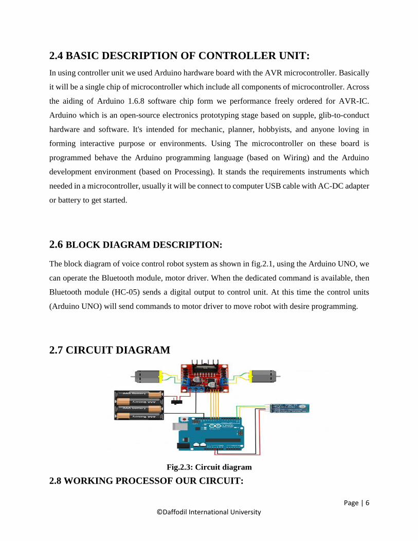
2.7 CIRCUIT DIAGRAM
Fig.2.3: Circuit diagram
2.8 WORKING PROCESSOF OUR CIRCUIT:

Page | 7 ©Daffodil International University
This project the Bluetooth control voice activated robot project which called voice controlled
robot. These application mainly controls the specific commands to prepare to our robot. In time
when toggle buttons are pressed these specific commands are passed by the voice apps and that’s
command we get a execute output for robot. The software Arduino which finds out the signal was
sent and compares it to the predefined for signal assigned for all application. Then it looking for
active the motor from identifies that signal which passing by 5v.Then the motor driver is on and
from specific command the motor driver is turned to move the robot.
2.9 LIST OF COMPONENTS USED IN CIRCUIT:
No Component Name Quantity Used
01 Bluetooth Module (HC-05) 01 To direct
communication.
02 Microcontroller:-
ATmega328P(Arduino UNO) 01 To Control the
System.
03 Motor driver 01 To run robot
04 Arduino compiler To compile code.
04 Amr voice Apps 01 To giving
command.
06 12v battery 02 Power Supply
07 Wires 19 To connection.
09 Led 03 Fabrication
10 Servo & sonar sensor 1+1 Rotate head
11 Sonar sensor 1 Giving eye shape
2.10 CONCLUSION:

Page | 8 ©Daffodil International University
The voice control robot which used in many applications because of its desirable properties like
homes, hostels, industries, vehicles, toy for children, playing device for mature kids. Open
source robot practice and many more

Page | 9 ©Daffodil International University
CHAPTER 3
COMPONENT DESCRIPTION
3.1 INTRODUCTION
System hardware design composed of Arduino Uno, L298N motor driver module, Servo motor
sg90, ultrasonic sensor for fabrication,16x2 lcd, display, DC motor Bluetooth Module (HC-
05),Some Wires, Arduino compiler, Android apps and obviously with power supply. In this
chapter we will discuss about component description, features, working procedure and cost
analysis of our all component.
3.2 DESCRIPTION OF BLUETOOTH MODULE (HC-05)
Recently everything goes to wireless such as phones computers, game controller, consoles and
many other. Without wire technologies has allowed us to use electronic device with unbounded
freedom to use without many others problem. Nowadays there are many types of wireless
connectivity like as Wi-Fi, cellular information, ZigBee and the most well –liked and wide used
wireless pools using Bluetooth. The 5 standard Bluetooth was announced the year in 2016 and
looking the Bluetooth 4.2 standard is commonly used this moment.
In our project using HC-05 model of Bluetooth module which is easy to use and setup. The HC-
05 which is used in a master of of salve configuration to do great solution and grat a smooth output
for a great communication.

Page | 10 ©Daffodil International University
Fig. 3.1.1: Bluetooth Module (HC-05)
3.2.1 FEATURES OF BLUETOOTH MODULE (HC-05):
Hardware Features
• Typical 80dBm sensitivity.
• Up to +4dBm RF transmit pour.
• 3.3 To 5v I-O.
• PIO that’s means Programmable I-O Control.
• With integrated antenna.
• With edge connector.
Software Features
• Slave default Baud rate: 9600, Data bits: 8, Stop bit: 1, Parity: No parity.
• Auto‐connect to the last device on power as default.
• Permit pairing device to connect as default.

Page | 11 ©Daffodil International University
3.2.2 PIN DESCRIPTIONOF HC-05:
Fig 3.1.2: Pins of HC-05
Sl. Pin Name Description
1. +5V or 3.3V +5V supply or Power Pin.
2. TX The Data/Command to be transmitted is sent
through this pin.
3. RX The Received data is read from this pin.
4. KEY/EN Input pin, which alters module between the
Data mode and the AT Command mode.
5. STATE Output pin, the state of the module is indicated
through this pin.
6. GROUND 0V / GND or Power Pin
Table: 3.1.3: HC-05 pin description

Page | 12 ©Daffodil International University
3.2.3 SUMMARY:
In the end this is a very good device to use in home or industry. This is a low cost project so that
it is very cost effective and efficient. In short term uses of communication it is better than other
wireless communication.
3.3 BASIC DESCRIPTION OF ANDROID APPLICATION:
An associate degree droid app may be a code application running on the robot platform. As a result
of the robot platform is constructed for mobile devices, a typical robot app is meant for a
smartphone or a pill laptop running on the robot OS. Though associate degree robot app square
measure usually created on the market by developers through their websites, most robot apps
square measure uploaded and printed on the robot Market, an online store dedicated to those
applications. The robot Market options every free and priced apps. Robot apps square measure
written within the Java programing language and use Java core libraries. They’re first compiled to
Dalvi possible to run on the Dalvi virtual machine, which can be a virtual machine specially
designed for mobile devices.

Page | 13 ©Daffodil International University
3.3.1 VOICE APPLICATION:
.
Fig 3.2: Arm voice Android Apps.
3.4 BASIC DESCRIPTION OF CONTROLLER UNIT:
The controlled we are used in radio hardware board with AVR microcontroller. This time with the
help of Arduino 1.6.8 plate from we can easily create a programmer IC, Arduino is an open source
electronic platform based on flexible which to easy hardware software. The Arduino UNO is
mainly a microcontroller single chip which has 14 digital input output pin that’s contains 6 PWM
and 6 are analog pins, All are requirements instruments are involved the Arduino which are
controlled a microcontroller. There are also a USB connector and a reset button and 6 MHz
oscillator a power jacket all are include it.
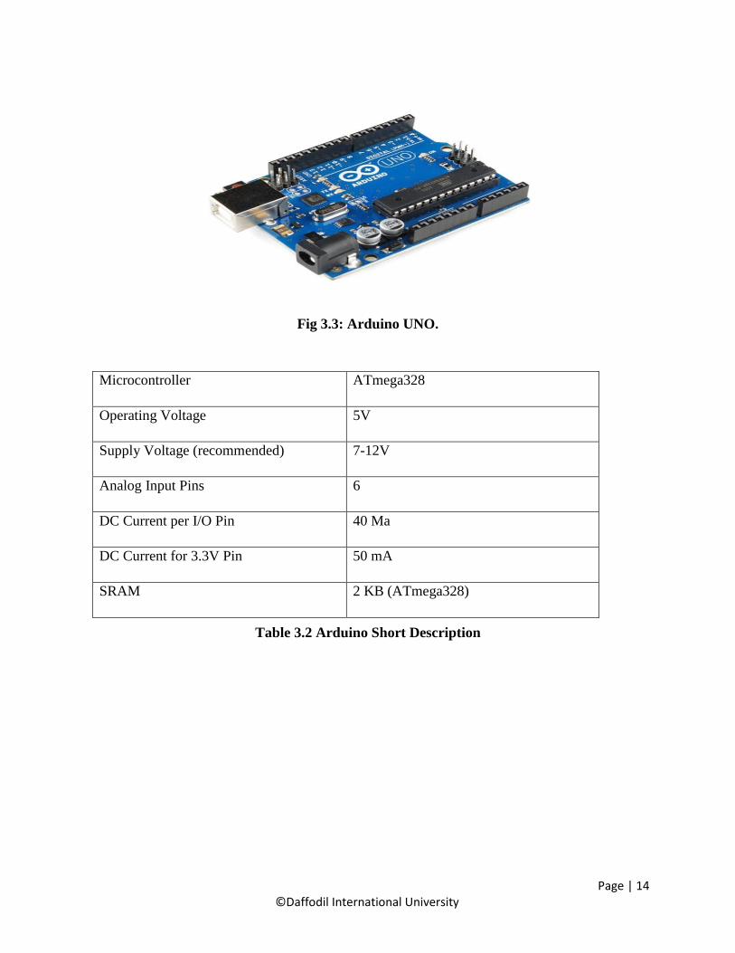
3.4.1 TECHNICALSPECIFICATION ARDUINOUNO
Page | 14 ©Daffodil International University
Fig 3.3: Arduino UNO.
Microcontroller ATmega328
Operating Voltage 5V
Supply Voltage (recommended) 7-12V
Analog Input Pins 6
DC Current per I/O Pin 40 Ma
DC Current for 3.3V Pin 50 mA
SRAM 2 KB (ATmega328)
Table 3.2 Arduino Short Description

Page | 15 ©Daffodil International University
3.4.2 DESCRIPTION OF MICROCONTROLLER: ATMEGA328:
Fig 3.3(b): Arduino UNO
The Arduino Uno may be a microcontroller board supported the ATmega328 (datasheet). it's
fourteen digital input/output pins (of that half dozen will be used as PWM outputs), half dozen
analog inputs, a sixteen megahertz oscillator, a USB association, an influence jack, Associate in
Nursing ICSP header, and a push. It contains everything required to support the microcontroller;
merely connect it to a laptop with a USB cable or power it with Associate in Nursing AC-to-DC
adapter or battery to urge started.

Page | 16 ©Daffodil International University
3.4.3 BLOCK DIAGRAM OF MICROCONTROLLER – (ATMEGA328):
Fig. 3.3.1: Block Diagram of Microcontroller – (Atmega328)

Page | 17 ©Daffodil International University
3.4.4 PIN CONFIGURATIONS OF MICROCONTROLLER –
(ATMEGA328):
Fig. 3.3.2: Pin Configurations of Microcontroller – (Atmega328)
3.4.5 PIN DESCRIPTIONS:
The below gives a description for each of the pins, along with their function:-
These pins are as follows:
• VIN: This pin basically input voltage to the Arduino board when it is using an external power
source.
• 5V: This time used power supply to the microcontroller and other components in these board.
• 3V3: The 3.3 voltage supplies generate under the on-board regulator. This time maximum
50mA current flowed.
• GND: Ground pins generated.
There are a couple of other pins on the board:
• AREF: Reference voltage for the analog inputs. Used with analog Reference.

Page | 18 ©Daffodil International University
• Reset: Bring this line LOW to reset the microcontroller. Typically used to add a reset button to
shields which block the one on the board.
Memory: The At mega 328 has 32 Kb of flash memory for storing code which 0.5 KB is used
for the bootloader and 2 KB of SRAM and 1 KB of EEPROM which also be read and written
with the EEPROM library.
3.5 L298N MOTOR DRIVER
L298N is a dual H-bridge motor driver. Motor drivers act as current amplifiers since they take a
low-current control signal and supply a higher-current signal. This higher current signal is
employed to drive the motors. L2938 contains 2 inherent H-bridge driver circuits. In its common
mode of operation, 2 DC motors can be driven at the same time, each in forward and reverse
direction. The motor operations of two motors can be controlled by input logic at pins 2 & 7 and
10 & 15. Input logic 00 or 11 will stop the corresponding motor. Logic 01 and 10 will rotate it in
clockwise and anticlockwise directions, respectively.
Fig 3.4: L298N Motor Driver
Enable pins ENA and ENB (corresponding to the two motors) must be high for motors to start
operating. A simple schematic for interfacing a DC motor using L298N is shown below.
Page | 19 ©Daffodil International University
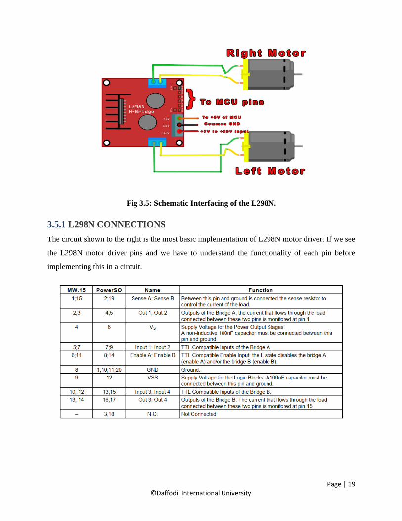
Fig 3.5: Schematic Interfacing of the L298N.
3.5.1 L298N CONNECTIONS
The circuit shown to the right is the most basic implementation of L298N motor driver. If we see
the L298N motor driver pins and we have to understand the functionality of each pin before
implementing this in a circuit.

Page | 20 ©Daffodil International University
Table 3.3 L298N driver pin specification
3.5.2 VOLTAGE SPECIFICATION
Table 3.4 L298N driver voltage specification
3.6: DESCRIPTION OF LCD DISPLAY 16x2
Using the LCD (Liquid Crystal Display) is a thin which is flat and made of any number of color
or monochrome pixels in front of a source of light or reflector. Every pixel consists of a column
of liquid crystal molecules suspended between two transparent electrodes, and two polarizing
filters, the axes of polarity of which are perpendicular to each other. For 16×1 LCD, the address
locations are:
Table 3.5: Address locations for a 1x16 line LCD
3.6.1 SHAPES AND SIZES:

Page | 21 ©Daffodil International University
Fig 3.6: LCD Different Models.
3.6.2 PIN DESCRIPTION:
Most LCDs with 1 controller has 14 Pins and LCDs with 2 controller has 16 Pins (two pins are
extra in both for back-light LED connections).
Fig 3.7: Pin Diagram of 1x16 lines LCD

Page | 22 ©Daffodil International University
Table 3.6: Pin Description of LCD
3.6.4. INITIALIZATION BY INSTRUCTIONS:
Fig 3.8.: Flow Chart of Installation

Page | 23 ©Daffodil International University
3.7 DC MOTOR
A DC motor is intended to run on DC wattage. 2 samples of pure DC styles square measure
archangel Faraday's homoploid motor (which is uncommon), and also the ball bear in motor, that
is (so far) a novelty. far and away the foremost common DC motor sports square measure the
brushed and brushless sorts, that use internal associate degreed external commutation severally to
make an periodic AC current from the DC supply -- so that they don't seem to be strictly DC
machines during a strict sense.
Fig 3.9: DC Motor.
3.7.1 TYPES OF DCMOTORS
• Brushed DC Motors
• Brushless DC motors
• Coreless DC motors
3.7.2 WORKING OR OPERATING PRINCIPLE OF DC MOTOR
A dc motor simple words is a device that converts direct current (electrical energy) into mechanical
energy. The very basic construction contains a current carrying armature which is connected to the
supply end through commutator segments and brushes and placed within the north south poles of
a permanent or an electro-magnet as shown in the diagram below.

Page | 24 ©Daffodil International University
Fig 3.10: Operation of DC Motor.
For clear understanding the principle of DC motor we have to determine the magnitude of the
force, by considering the diagram below.
Fig 3.11: Magnitude of the force for DC Motor.
We know that when an infinitely small charge dq is made to flow at a velocity ‘v’ under the influence of
an electric field E, and a magnetic field B, then the Lorentz Force dF experienced by the charge
3.8 BASIC ARDUINO SOFTWARE:

Page | 25 ©Daffodil International University
Fig 3.11: Arduino Software
3.8.1 FEATURES OF ARDUINO SOFTWARE:
• File
• Edit
• Sketch
• Tools
• Help
3.9 WIRES:
Fig 3.11(a): Female to Male Jumper Wire. Fig 3.11(b): Male to Male jumper
3.10 POWER SUPPLY 12V:

Page | 26 ©Daffodil International University
The automaton ar powered from 12v lip battery. The inner electronic equipment of associate
external power provide is extremely the same as the look that might be used for a intrinsic or
internal provide. External power provides ar used each with instrumentality with no different
supply of power and with powered instrumentality
Fig 3.12: 12v Power supply
3.10.1 SPECIFICATIONS:
• Capacity: 1100mAh
• Voltage: 11.1V (3S)
• Discharge Rating: 30C
• Charge Rate: 2C
• Dimensions: 138x46x35.5mm
• Weight: 300g
3.11 COST ANALYSIS
In this section we will show cost of our project that means cost sheet representation of our project.
3.11.1 COST SHEET:

Page | 27 ©Daffodil International University
No Component Name Quantity Purchase Price
(TK)
01 Bluetooth Module(HC-05) 1 350.00
02 Arduino UNO 1 450.00
03 L298N motor driver 1 400.00
06 Amr voice app 1 Free
07 Battery and charger 1 1900.00
08 Arduino Software 1 Free
09 Wires 8 100.00
10 Pvc board 1 200
11 Servo motor 1 180
12 Others 500
Total Cost =4080.00
Comparison:-
Our all components are available in market. We get all components are very reasonable price. So
that we make this project more cost efficient.
3.12 CONCLUSION
Five main Component & some tools are used in this system to makes it .This Project is used to
control the house appliances. Our all component are very simple &available in our country market.

Page | 28 ©Daffodil International University
CHAPTER 4
SOFTWARE ANALYSIS
4.1 INTRODUCTION
In this chapter the software system used and therefore the language within which the program code
is outlined is mentioned and therefore the program code selling tools square measure explained.
The chapter additionally documents the event of the program for the applying.
4.2 DESCRIPTION OF OUR SOFTWARE
The open-source Arduino environment makes it easy to write code and upload it to the I/O board.
It runs on Windows, Mac OS X, and Linux. The environment is written in Java and based on
Processing, avr-gcc, and other open source software. The screen shot of Arduino 1.6.8 is shown
below.
Fig. 4.1: Software Platform
The Arduino IDE comes with a C/C++ library called "Wiring" (from the project of the same name),
which makes many common input/output operations much easier. Arduino programs are written
in C/C++, although users only need define two functions to make a runnable program:

Page | 29 ©Daffodil International University
setup() – a function run once at the start of a program that can initialize settings
loop() – a function called repeatedly until the board powers off
The compiled window of our code is shown below.
Fig. 4.2: Compiling window
4.3 Flow Chart Diagram
POWER ON

Page | 30 ©Daffodil International University
ARDUNIO UNO…OK
BLUETOOTH MODLE.OK
NO
BLUETOOTH MODULE = LOW
NO
Yes
Fig. 4.3: Flow chart of our system
4.4 CONCLUSION
The system software developed in Embedded C, C++ language which has the ability of receiving
the data from sensor and transmitting the data, and controls all the Robot that connected. Because
of its low power consumption, easy usage, reliability it is used in other fields. Software analysis is
a very important part of our system. A Software analysis makes sure good design. A proper
Software analysis and its burn into Arduino Uno the project to a smooth end.

Page | 31 ©Daffodil International University
CHAPTER 5
SCHEMATICREPRESENTATION
5.1 INTRODUCTION
A schematic, or schematic diagram, is associate degree illustration of the weather of a system
mistreatment abstract, graphic symbols rather than realistic photos. A schematic typically omits
all details that are not relevant to the data the schematic is meant to convey, and can add delusive
elements that aid comprehension. as an example, a subway map meant for riders might represent
a terminal with a dot; the dot does not fit the particular station in any respect however offers the
viewer data while not unnecessary visual muddle. A schematic diagram of a action uses symbols
to represent the vessels, piping, valves, pumps, and different instrumentation of the system, action
their interconnection methods and suppressing physical details.
5.2 SCHEMATIC DIAGRAM
In the previous chapters we got an idea about project block diagram and functions of each block
in detail. In this chapter we seen schematic representation of the project and various components
what are involved in this project. The below figure shows the schematic representation of the
project.

Page | 32 ©Daffodil International University
Fig 5.1: Circuit Diagram
After seen the above diagram we have an idea about each and every pin connection of
microcontroller involves in the project. The wire connections in the project are very important.
The various components involved in this project are:
• CRYSTAL OSCILATOR
• RESISTORS
• SWITCHES
• MOTORS
• WHEELS
• PVC BOARD
• SONAR
• SERVO
• LCD
• MICROCONTROLLER

Page | 33 ©Daffodil International University
• DRIVER MODULE
• REGULATOR
• CONNECTIG WIRES
• BATTERY AND CHARGER
•
5.2.1 CRYSTAL OSCILLATOR
It is an electronic circuit that uses the mechanical resonance of a moving crystal of piezoelectric
material to make an electrical signal with an awfully precise frequency. This frequency is often
accustomed keep track of your time (as in quartz wristwatches). In this project crystal oscillator
frequency is 11.0592 MHz. The below figure shows the crystal oscillator.
Fig 5.2: Crystal Oscillator
5.2.2 RESISTOR
The resistor is a passive electrical component which create resistance for flowing electric current
.Almost all are electrical networks and electronic circuits which can be found .The resistance in
measuren in ohms, an ohms is the resistance tat occurs when a current of one ampere passes
through a resistor within one voltage drop across it’s terminals.Basically resistor are used in many
purpose ssuch as current ,voltage division heat generation, matching and loading circuits.

Page | 34 ©Daffodil International University
5.2.3 SWITCHES
In engineering switch plays a important role that can break an electrical circuit delivering one
conductor to another conductor.The most identical to manually controlled to electromechanical
device eith one or more sets of electrical external circuits.Each contacts can be two states one is
open and another is closed. Open means contacts are separate and switch is no conducting and
closed means contacts are touching and electricity flow between them.Switches are the depends
upon the closed conduct and open conduct
5.2.4 MOTORS
A DC motor is an electric motor which runs that an direct electric power. Mainly any electric
motor operation depends upon the electromagnetism. A current carrying conductor produces a
magnetic field and torque when it is placed in an external magnetic field. Examples of pure DC
are Michael Faraday's homo polar motor (which is uncommon), and the ball bear in motor, By far
the most common DC motor types are the brushed and brushless types. In any electric motor,
operation is based on simple electromagnetism. Mainly it converts electrical energy to mechanical
energy.
5.2.5 LCD
LCD means liquid crystal display is a flat display made up of color or pixels front of a light source
.It’s the common that an LCD display controlled an attached device. Every pixels consist of a
column of liquid crystal display between two transparent electrodes. The LCD which connected
to the controller 16X1 and two polarizing filters. The specific given commands output will show
the display. It depends upon the execute program.
5.2.6 MICROCONTROLLER
The true computer on a chip is nothing but a microcontroller. The design incorporates all of the
features found in a microprocessor CPU, ALU, PC, SP and registers.

Page | 35 ©Daffodil International University
5.2.7 DRIVER MODULE
L298N is a dual H-bridge motor driver module. Motor drivers act as current amplifiers since they
take a low-current control signal and provide a higher-current signal. This higher current signal is
used to drive the motors. L298N is a dual H-Bridge motor driver.
5.2.8 CHARGED BATTERIES
Batteries are used to give a electric supply to run the electronic devices, machines, to run the
vehicles. Batteries are also helpful in storage purpose. When power supply is not available then
we will follow the storage batteries or batteries. Batteries are low cost, can be rechargeable. No
expansive.
5.2.9 REGULATOR
A transformer is AN electrical regulator designed to mechanically maintain a continuing voltage
level. Electronic voltage regulators square measure found in devices like laptop power provides
wherever they stabilize the DC voltages utilized by the processor and alternative components.
5.3 CONCLUSION
From this chapter we conclude that Fig 6.1 shows the schematic diagram of voice control robot
through android. This fig shows the overall project representation of the project and we are able to
know in which way every pin of the microcontroller involves in this project. And also we are
discussed about each component in this project. Fig 6.1 shows the schematic diagram of voice
control robot through android. This fig shows the overall project representation of the project and
we are able to know in which way every pin of the microcontroller involves in this project. And
also we are discussed about each component in this project.

Page | 36 ©Daffodil International University

Page | 37 ©Daffodil International University
CHAPTER 6
RESULT AND DISCUSSION
6.1 INTRODUCTUION
In this chapter we'll discuss regarding the assembling process of voice control robot through
android and assembling method. During this we'll additionally discuss regarding android, android
applications. However the humanoid are going to be helpful during this project. That android
applications are utilized in this project? Within the android applications however the commands
are used to control the robots and additionally during this chapter we'll discuss regarding robot’s
operating mechanism. They’re briefly explained below.
6.2 ASSEMBLING THE BOARD
The chassis used for this thesis is hand made in home with pvc board with relatively use in making
Chassis, which is widely used for robotics project chases plates and tools. Total assembling process
is shown in below chapters.
Fig 6.1: Hardware board

Page | 38 ©Daffodil International University
6.2.1 ASSEMBLING PROCESS
Fig 6.2: Circuit Board

Page | 39 ©Daffodil International University
6.2.2 COMPLETION OF ASSEMBLING PROCESS
Fig: 6.2.1 Our Project
6.3 ANDROID APPLICATIONS
These android applications are used to design. They are given as follows
i) Bluetooth spp test
ii) ii) Bluetooth AMR (Android meets robot)
6.3.1 BLUETOOTH SPP TEST
Bluetooth SPP test is an android application to move robot. It is also available in Google play
store. In this applications we will run the robot by using a commands like 2,4,6,8,5.in this
application 2 is used to move the robot forward,4 is to move left side,6 is used to move right side,8
is used to move backward.5 is used to STOP. These are the commands used for moving robot.
6.3.2 BLUETOOTH AMR (ANDROID MEETS ROBOT).

Page | 40 ©Daffodil International University
It is also a android application to move robo.It is also available in Google play store. Inthis
application we will run the roboby using a voice commands. By using this applicationwe will give
voice commands only. In this application we will not give typing commands.
6.4 ROBOT’S WORKING MECHANISM
The working mechanism of the robot is based on the information passed from the android mobile
phone via Bluetooth connection to the robot using a Bluetooth modem and vice versa. When will
give a commands by android phone that will transmitt and receive the information signals.by
giving a commands it will move in the given command direction.here is the power supply is given
to robot by ecofriendly solar panel and storage batteries.by using both solar panel and batteries
we are capable to run the robo. If there is no power or no light energy then power supply is used
as vice versa.
Fig 6.3: Architecture
6.5 TESTING
From the following commands our robot will be follows. The following commands are same as
both android apps. What we given to robot via android whther it is voice command or touch
command the following commands are same for the robot movement.
COMMAND ROBOT MOVEMENT
Go back BACKWARD
Turn left LEFT
Stop STOP
Turn right RIGHT
Go ahead FORWARD
Table 6.1: Testing Result
6.6 CONCLUSION

Page | 41 ©Daffodil International University
In this chapter we were discussed about the assembling process of voice control robot. In this
chapter we were discussed about android, android applications. How the android applications are
used in this project. In this chapter we will discuss about robot’s working mechanism.

Page | 42 ©Daffodil International University
CHAPTER 7
CONCLUSION
7.1 APPLICATIONS:
Certainly we believed that a system would be find wide varite of applicable.Many driver systems
like as toys specially household applications like as washing machine, microwaven and pagers and
mobile many other form which will controlled by voice android apps in next.
7.1.1 HOME AUTOMATION
Nowadays due to much highest affordable and simplicity throughout smartphones and tab
connectivity respectively. Recently the popularities of the home automation increasing greatly in
recent years.
7.1.2 WHEELCHAIRS:
Mainly to operate our project the robot is controlled by a giving a specific commands in amr voice
apps. From giving the commands the robot will be move or stop.
Fig 7.2: Wheelchair Applications

Page | 43 ©Daffodil International University
7.1.3 SURVEILLANCE DEVICE:
It is the monitoring of other changing information, usually of people for the purpose of influencing.
7.1.4 MILITARY APPLICATIONS:
Our robot is mobile robot which plays an important role in military matters.With the suitable sensor
and smooth camera these robots are operated. All the work will be the firms are getting easily from
the mobile robot.
Fig 7.4: Military Applications
7.2 ADVANTAGES
• Using this robot we can controlled live video feed under giving specific commands.
• It can also be used to known any multiple ways such as clockwise, anticlockwise, forward and
backward direction.
• In industries purpose we contolled many oter machine by it.
• This robot is used in hazardous place.
• Execute can program make them to do exactly what I want to do something.

Page | 44 ©Daffodil International University
• You can send them to very dangerous places.
• They can do well something for job sectors.
• They can perform task faster than human beings it will be worked any place.
• We send it a dangerous place where are people are not reached.
• They can also use in physically treatment person for helping moving.
• They can reduce the labor work in industry by it portable takes the load from one place to
another place. They able to work always 24x7.
• DISADVANTAGES
It will be very expensive to do better fabrication.
• For produce it exact material that’s the demerit also.
• Execute this project very hard to program.
• You need highly trained people to make them.
• People can lose jobs in factories.
• It needs maintenance to keep it running.
7.4 FUTURE SCOPE:
The main object such robot system is to assist individuals with motor disabilities it controlling
completely. In future time we use a secured wireless channel using secret writing and
cryptography. There are many scope will be held in future such as AI movements speech to text
translation and lots of additional. It also be in agricultural scope to additionally develop under
artificial intelligence. In future larger bandwidth system will be developed by this project. There
are a number of interfacing applications might be created for home applications

Page | 45 ©Daffodil International University
REFERENCES:
• https://www.arduino.cc/en/Tutorial/RobotRemoteControl
• https://www.instructables.com/id/Voice-Control-Robot-in-7-Minutes/
• https://www.robotshop.com/community/robots/show/voice-control-arduino-robot
• https://tronixlabs.com.au/news/tutorial-l298n-dual-motor-controller-module-2a-and-
arduino/
• http://wiki.sunfounder.cc/index.php?title=Motor_Driver_Module-L298N
• https://components101.com/wireless/hc-05-bluetooth-module
• https://amr-voice.en.aptoide.com/
• Scribd.com, the world’s largest online library. URL:http://www.scribd.com
• Encyclopedia of regulators, capacitors, diodes, resistors
• http://www.morldtechgossips.com simple way of understand
• Other websites
• http://www.elprocus.com/solar-panel-facts/
• http://org.ntnu.no/solarcells/pages/introduction.php
• http://www.facstaff.bucknell.edu
• http://hyperphysics.phy-astr.gsu.edu/hbase/electronic/leds.html
• www.national.com
• www.atmel.com
• www.microsoftsearch.com
• www.geocities.com

Page | 46 ©Daffodil International University
APPENDIX A
#include <LiquidCrystal.h>
#include <Servo.h>
String voice;
int
in1 = 2, //MORTORPIN 1 To Pin #2
in2 = 3, //MOTORPIN 2 To Pin #3
in3 = 4, //MOTORPIN 3 To Pin #4
in4 = 5, //MOTORPIN 4 To Pin #5
IN5 = 6, // RED LED
IN6 = 7; // GREEB LED
//--------------------------Call A Function-------------------------------//
const int rs = A5, en = A4, d4 = A3, d5 = A2, d6 = A1, d7 = A0;
LiquidCrystal lcd(rs, en, d4, d5, d6, d7);
int i = 0;
int pos;
Servo myServo;
void setup() {
Serial.begin(9600);
lcd.begin(16, 2);
myServo.attach(10);
myServo.write(90);
pinMode(in1, OUTPUT);
pinMode(in2, OUTPUT);
pinMode(in3, OUTPUT);
pinMode(in4, OUTPUT);

Page | 47 ©Daffodil International University
pinMode(IN5, OUTPUT); //A0 is output pin
pinMode(IN6, OUTPUT); //A1 is output pin
////lcd print///
lcd.setCursor(0, 0);
lcd.print(" Welcome to our ");
delay(1000);
lcd.clear();
lcd.setCursor(1, 0);
lcd.print(" Project ");
delay(1000);
lcd.clear();
}
void loop()
{
while (Serial.available()) { //Check if there is an available byte to read
delay(10); //Delay added to make thing stable
char c = Serial.read(); //Conduct a serial read
if (c == '#') {
break; //Exit the loop when the # is detected after the word
}
voice += c; //Shorthand for voice = voice + c
}
if (voice.length() > 0) {
if (voice == "*go ahead") {
forward_car();
}
else if (voice == "*go back") {

Page | 48 ©Daffodil International University
back_car();
}
else if (voice == "*turn right") {
right_car();
}
else if (voice == "*turn left") {
left_car();
}
else if (voice == "*stop") {
stop_car();
}
voice = ""; //Reset the variable after initiating
}
digitalWrite(IN5, HIGH);
delay(500);
digitalWrite(IN5, LOW);
delay(500);
digitalWrite(IN6, HIGH);
delay(500);
digitalWrite(IN6, LOW);
delay(500);
}
void forward_car()
{
digitalWrite(in2, LOW);
digitalWrite(in4, LOW);
digitalWrite(in1, HIGH);

Page | 49 ©Daffodil International University
digitalWrite(in3, HIGH);
delay(1000);
lcd.setCursor(0, 0);
lcd.print("GOING Forward");
delay(1500);
lcd.setCursor(0, 1);
lcd.print("NeXT COMMAND");
delay(800);
lcd.clear();
digitalWrite(IN5, HIGH);
delay(500);
digitalWrite(IN5, LOW);
delay(500);
digitalWrite(IN6, HIGH);
delay(500);
digitalWrite(IN6, LOW);
delay(500)
}
void back_car()
{
digitalWrite(in1, LOW);
digitalWrite(in3, LOW);
digitalWrite(in2, HIGH);
digitalWrite(in4, HIGH);
delay(1000);
lcd.setCursor(0, 0);
lcd.print("GOING BACKWARD");

Page | 50 ©Daffodil International University
delay(1500);
lcd.setCursor(0, 1);
lcd.print("NeXT COMMAND");
delay(800);
lcd.clear();
digitalWrite(IN5, HIGH);
delay(500);
digitalWrite(IN5, LOW);
delay(500);
digitalWrite(IN6, HIGH);
delay(500);
digitalWrite(IN6, LOW);
delay(500);
}
void right_car()
{
myServo.write(0);
delay(1000);
myServo.write(90);
delay(1000);
digitalWrite(in1, LOW);
digitalWrite(in3, HIGH);
digitalWrite(in2, LOW);
digitalWrite(in4, LOW);
delay(800);
lcd.setCursor(0, 0);
lcd.print("GOING RIGHT");

Page | 51 ©Daffodil International University
delay(1500);
lcd.setCursor(0, 1);
lcd.print("NeXT COMMAND");
delay(800);
lcd.clear();
digitalWrite(IN5, HIGH);
delay(500);
digitalWrite(IN5, LOW);
delay(500);
digitalWrite(IN6, HIGH);
delay(500);
digitalWrite(IN6, LOW);
delay(500);
}
void left_car()
{
myServo.write(180);
delay(1000);
myServo.write(90);
delay(1000);
digitalWrite(in2, LOW);
digitalWrite(in4, LOW);
digitalWrite(in1, HIGH);
digitalWrite(in3, LOW);
delay(500);
lcd.setCursor(0, 0);
lcd.print("GOING LEFT");

Page | 52 ©Daffodil International University
delay(1500);
lcd.setCursor(0, 1);
lcd.print("NeXT COMMAND");
delay(800);
lcd.clear();
digitalWrite(IN5, HIGH);
delay(500);
digitalWrite(IN5, LOW);
delay(500);
digitalWrite(IN6, HIGH);
delay(500);
digitalWrite(IN6, LOW);
delay(500);
}
void stop_car()
{
digitalWrite(in1, LOW);
digitalWrite(in3, LOW);
digitalWrite(in2, LOW);
digitalWrite(in4, LOW);
lcd.setCursor(0, 0);
lcd.print("CAR STOP");
delay(1500);
lcd.setCursor(0, 1);
lcd.print("THANKS");
delay(800);
lcd.clear();

Page | 53 ©Daffodil International University
digitalWrite(IN5, HIGH);
delay(500);
digitalWrite(IN6, HIGH);
delay(500);
}