
Deploying Array Networks APV Application Delivery ... · Exchange Server 2010 environments, such as...
78
Deployment Guide Jan-2016 rev. a Deploying Array Networks APV Application Delivery Controllers with Microsoft Exchange Server 2010
Transcript of Deploying Array Networks APV Application Delivery ... · Exchange Server 2010 environments, such as...

Deployment Guide
Jan-2016 rev a
Deploying Array Networks
APV Application Delivery Controllers
with Microsoft Exchange Server 2010
1 Introduction 5
11 Prerequisites amp Assumptions 5
111 Exchange Server 2010 5
112 Array Networks APV Appliance 5
12 Introduction to Exchange Server 2010 6
121 Exchange Server 2010 Architecture 6
122 Exchange Server 2010 Load Balancing Requirements 7
13 APV Series Application Delivery Controller (ADC) Benefits 7
14 Deployment for Exchange Server 2010 Roles 8
15 Array Networks Solution for Exchange Server 2010 Deployments 10
16 Verification Tools 10
17 APV Configuration Summary 11
18 Preconditions 11
2 Configuring APV for Outlook Web App 13
21 Configuration Steps 13
211 Create the Outlook Web App Service Health Check (Optional) 13
212 Create an Outlook Web App Real Service 14
213 Create the Outlook Web App Service Group 16
214 Create the Outlook Web App Virtual Service 18
215 Enable Outlook Web App SSL Offloading 20
216 Enable Outlook Web App RewriteRedirect 23
3 Configuring APV for Outlook Anywhere 27
31 Configuration Steps 27
311 Create Outlook Anywhere Service Health Check 27
312 Create Outlook Anywhere Real Service 28
313 Create the Outlook Anywhere Service Group 28
314 Create Outlook Anywhere Virtual Service 29
315 Enable Outlook Anywhere SSL Offloading 30
316 Complete Mail Configurations on the Client 31
317 OWAOA Single Virtual Service Support 31
4 Configuring the APV Appliance for ActiveSync 32
41 Configuration Steps 32
411 Create ActiveSync Service Health Check 32
412 Create ActiveSync Real Service 33
413 Create ActiveSync Service Group 33
414 Create ActiveSync Virtual Service 34
415 Enable ActiveSync SSL Offloading 35
416 Misc ndash Change TCP Idle Timeout 36
5 Configuring the APV Appliance for RPC Client Access 37
51 Configuration Steps 37
511 Create RPC Client Access Service Health Check 37
512 Create RPC Client Access Real Service 37
513 Create RPC Client Access Service Group 38
514 Create RPC Client Access Virtual Service 39
6 Configuring the APV Appliance for POP3 42
61 Configuration Steps 42
611 Create POP3 Service Health Check 42
612 Create POP3 Real Service 42
613 Create POP3 Service Group 43
614 Create POP3 Virtual Service 43
615 Enable POP3 SSL Offloading 44
7 Configuring the APV Appliance for IMAP4 46
71 Configuration Steps 46
711 Create IMAP4 Service Health Check 46
712 Create IMAP4 Real Service 46
713 Create IMAP4 Service Group 47
714 Create Secures IMAP4 Virtual Service 47
715 Enable IMAP4 SSL Offloading 48
8 Configuring the APV Appliance for SMTP (Edge Transport) 50
81 Configuration Steps 50
811 Create SMTP (Edge Transport) Service Health Check 50
812 Create SMTP (Edge Transport) Real Service 50
813 Create SMTP (Edge Transport) Service Group 51
814 Create SMTP (Edge Transport) Virtual Service 52
815 Enable SMTP (Edge Transport) SSL Offloading 53
816 Misc SMTP Outbound Support 53
9 Configuring the APV Appliance for Link Redundancy Using LLB 55
91 Configuration Steps 55
911 Add additional port for WAN-2 access 55
912 Add Duplicate Virtual Service for WAN 2 access 56
913 Create LLB Links information 57
914 Create LLB DNS record for inbound traffic 58
10 Configuring the APV Appliance for Exchange 2010 Site Resilience Using GSLB 60
101 Fault Tolerance Configuration 61
102 Configuration Steps 61
1021 Define GSLBSDNS Members 61
1022 Creating GSLB Records 61
1023 GSLBSDNS Disaster Recovery Site Location 62
1024 Creating a DR Group with DNS domain name 63
1025 Setup GSLBSDNS with BIND 9 64
1026 GSLBSDNS DR Deployment Verification 65
1027 Log Information 67
11 Summary 70
Appendix I 71
1 Introduction
11 Prerequisites amp Assumptions
111 Exchange Server 2010
This document is written with the assumption that you are familiar with Microsoft Exchange
Server 2010 products For more information on planning and deploying the Exchange
Server 2010 please reference the appropriate documentation at
httpstechnetmicrosoftcomen-uslibrarybb124558(v=exchg141)aspx
112 Array Networks APV Appliance
The APV appliance must be running version ArrayOS TM 8x or later For more information
on deploying the APV appliance please refer to the ArrayOS TM Web UI Guide which is
included in the product CD or accessible through the product Web user interface
We assume that the APV appliance is already installed in the network with management IP
interface IP VLANs and default gateway configured
Learn about your Exchange Server 2010 deployment in your network and note down VLAN
information IP addresses and port numbers for various Client Access Servers (CAS) and
Edge Transport Servers (ETS) and their roles You will need them for configuring virtual
sites and load balancing policies on the APV appliance
Edge Transport
Routing amp
AVAS
12 Introduction to Exchange Server 2010
The Exchange Server 2010 is designed to provide users with the freedom to securely access all of
their communicationsmdashemail voice mail instant messaging and moremdash from virtually any platform
Web-browser or device regardless of where they are
121 Exchange Server 2010 Architecture
The Exchange Server 2010 architecture consists of different server roles
Enterprise Network
Unified M
Figure 1-1 Exchange Server 2010 Architecture
Client Access Server This is the server that receives mail requests from remote
and internal users from a variety of end user devices
Edge Transport Server This is the mail routing server that typically sits at the
perimeter of the topology and routes mail into and out of the Exchange Server 2010
environment
Mailbox Server This server hosts mailboxes and public folders
Unified Messaging Server This is the server that connects a Private Branch
Exchange (PBX) system to Exchange 2010
Hub Transport Server This is the mail routing server that routes mail within the
Exchange organization
ETS External SMTP
Servers
Mobile phone
Outlook (remote user)
Phone System (PBX or VoIP)
CAS
Outlook (local user)
Line of Business Application
CAS Client Access Servers ETS Edge Transport Services
Hub Transport Routing amp Policy
Mailbox Storage of
Mailbox Items
Unified Messaging Voice Mail amp Voice Access
Client Access Client Connectivity
Web Services
122 Exchange Server 2010 Load Balancing Requirements
Microsoft recommends a hardware load balancer for the purposes of incorporating high
availability site resiliency scalability and security to the Exchange Server environment Also
due to various Exchange Server roles and services session persistence support on the load
balancer is an important requirement
13 APV Series Application Delivery Controller (ADC) Benefits
The Array Networks APV Series delivers all required functions for optimizing application delivery for
Exchange Server 2010 environments such as Layer 4-7 server load balancing high availability
SSL acceleration and offloading DDoS protection TCP connection multiplexing caching and
compression ndash all in a single easy-to-manage appliance
Availability amp Scalability
The APVlsquos server load balancing ensures 99999 uptime for Exchange Server 2010 deployments
Customers can scale their Exchange environment to meet capacity and performance needs with
APV server load balancers
Site Resilience
The APVlsquos global server load balancing directs traffic away from failed data centers and intelligently
distributes services between sites based on proximity language capacity load and response times
for maximum performance and availability
ISP Link Availability
The APVlsquos link load balancing with advanced link failover and bandwidth management optimizes
the availability security cost and performance of Exchange Server 2010 deployments across
multiple WAN connections
SSL Offloading
The APV appliance offloads 1024-bit and 2048-bit SSL encryptiondecryption from Exchange 2010
Servers to improve performance and reduce the number of Exchange 2010 servers required to
support high volume secure mail processing
TCP Connection Multiplexing
The APV appliance multiplexes several client TCP connections into fewer Exchange Server 2010
TCP connections for increase throughput and performance The APV appliance also reuses
existing server connections
Session Persistence
The APV appliance performs session persistence for Exchange Server 2010 user traffic and
ensures that users are directed to same servers for the duration of their session
Cache Offload
The APV appliance serves frequently requested content from cache for increased performance and
scales the capacity of the Exchange 2010 Server environment
HTTP Compression
The APV appliance compresses and delivers Exchange Server 2010 mail attachments and
messages over LAN and WAN networks
Network and Server Protection
The APV appliance protects Exchange Server 2010 components (servers and services) from
malicious network and server attacks like DDoS attacks SYN floods TCP port scans UDP floods
and UDP port scans etc
14 Deployment for Exchange Server 2010 Roles
Exchange Server 2010 has two main roles when front ending end-users in the datacenter the
Client Access Server role and the Edge Transport server role
The Client Access Server role accepts connections to Exchange 2010 from different clients such
as but not limited to Microsoft Outlook
The five Client Access modes are
Outlook Web App (OWA) ndash access your email from any Web browser
Outlook Anywhere ndash access your email from the Internet using Microsoft Outlook
Messaging API (MAPI) over HTTP
ActiveSync ndash synchronize e-mail between your mobile phone and Exchange 2010
Remote Procedure Call (RPC) Client Access ndash access your email via Microsoft Outlook
MAPI
POP3IMAP4 ndash access your email from standard email clients
Other Client Access mode services
Exchange Web Services (EWS) ndash offers a Web services API
Autodiscovery ndash simplifies userslsquo profile configuration
Offline Address Book (OAB) distribution ndash OAB access via Web-based distribution for
Outlook clients
The Edge Transport server role performs anti-spam and antivirus filtering and applies messaging
and security policies to messages in transport in and out of datacenter
Simple Mail Transfer Protocol (SMTP) ndash Routes mail into and out of the Exchange Server
2010 environment
This guide gives you step-by-step procedures for configuring the APV appliance to optimize each
mode
15 Array Networks Solution for Exchange Server 2010 Deployments
Figure 1-2 Array Networks Load Balancing Solution for Exchange 2010
16 Verification Tools
To validate Exchange 2010 and the APV deployment Microsoft provides tools to generate
simulated Exchange workloads The following tools are recommended
Exchange Server Load Generator 2010
The Load Generator (LoadGen) tool is designed to produce a simulated client workload against a
test Exchange deployment LoadGen is capable of simulating Microsoft Office Outlook 2003 (online
and cached) Outlook 2007 (online and cached) and POP3 IMAP4 SMTP ActiveSync and
Outlook Web App client activity
For Outlook Local Users
Exchange Remote Connectivity Analyzer
Microsoft provides the online Exchange Remote Connectivity Analyzer for Exchange customers to
validate Internet access
17 APV Configuration Summary
The following table shows the APV configuration information used for Virtual Services and Real
Services
Application Service
Virtual Service Real Service
Affinity Health Check
Protocol Port Protocol Port
OWA HTTPS 443 HTTP 80 Cookie HTTP
Outlook Anywhere HTTPS 443 HTTP 80 None HTTP
ActiveSync HTTPS 443 HTTP 80 None HTTP
POP3 POP3-S 995 POP3 110 None TCP
IMAP IMAP4-S 993 TCP 143 None TCP
SMTP TCP 25 TCP 25 None TCP
RPC Client Access TCP 135 Port
range TCP any Client IP
PING+
Additional
18 Preconditions
For interworking between the APV appliance and the client make certain that you have imported
the root certificate which should be already obtained of the Exchange Server 2010 to the client
To import the root certificate of the Exchange Server 2010 to the client do as follows
1 On the client go to Start -gt Runhellip Enter ―certmgrmsc The following screen is
displayed
2 Right-click Trusted Root Certification Authorities -gt All Tasks -gt Import
Import the certificate according to Certificate Import Wizard
2 Configuring APV for Outlook Web App
Outlook Web App allows authorized users to securely access their Exchange mailboxes through a
Web browser By using APV load balancerstraffic managers in front of Outlook Web App servers
you gain the following high-availability and improved user experience benefits
The APV appliance can load balance and monitor application availability ensuring high-
availability across multiple Outlook Web App servers
The APV appliance provides SSL offloading and content cachingcompression features that
improve client performance and reduces server load
The APV appliance can transparently redirect HTTP to HTTPS for client requests
The APV appliance can transparently rewrite and redirect from HTTP to HTTPS for server
response
The APV appliance can alleviate security concerns such as DDoSSpike
OWA setup also can serve Exchange Control Panel (ECP) service
21 Configuration Steps
211 Create the Outlook Web App Service Health Check (Optional)
Make certain you are in Config mode and have selected the feature Real Services from the
sidebar [a] The configuration window will display two tabs [b] Real Services and Health
Check Setting
Figure 2-1 Add Real Service
Optional For a better OWA application service Health Check a simple HTTP content health
check can be better than a TCPICMP health check for service availability
1 Click on the Health Check Setting tab [b] a new window will display
2 Select ―3 HEAD HTTP11rnrn [see figure below]
3 Input the fields relating to the Response String
4 In our example we need to input GET OWAcascfm HTTP11rnHost
owadomaincomrnrn
5 Select ―3 200 OK
6 Input the fields relating to the Response String In our example we need to input
SERVICE IS UP
7 Finish the Health Check Setting by clicking SAVE CHANGES
Figure 2-2 Customize OWA Health Check Setting
Note The ldquocascfmrdquo is (an optional faked) Web page to help monitor CAS OWA
application availability You can use any Web page and check its returned content for
the application status
212 Create an Outlook Web App Real Service
Real Services are the three CAS servers Add each CAS server with its name IPport and
protocol information as a Real Service using the following steps
1 Select the action link ―Add Real Service Entry The configuration window will
present a new screen for SLB REAL SERVICES CONFIGURATION
Equivalent CLI Configuration
health request 3 GET OWAcascfm HTTP11rnHost
owadomaincomrnrn health response 3 SERVER IS UP
Figure 2-3 Enter SLB REAL SERVICES CONFIGURATION Screen
2 The ldquoAdd Real Service Entryrdquo screen is for you to configure real servers In our
example we enter ldquoowa-cas-1rdquo as the Real Service Name Select HTTP as the
Real Service type and enter IP addresses 10101011 and port 80
3 Select the HTTP health check type for the real service and configure the related
parameters for the health check Notice the parameter fields may vary with
different health check types Make certain you have set the Health Up Limit
and ldquoHealth Down Limitrdquo to 1 This indicates how many times for application
test failsuccess to declare the Real Service is ―Down or ―Up
4 Make certain you select the GET OWA HTTP11rnHost
owadomaincomrnrn and ldquo200 OKrdquo
5 Finish the creation of the real service and its health check configuration by clicking
ldquoSaverdquo on the desired action link
Figure 2-4 Create Real Service for OWA
Follow the same steps add ldquoowa-cas-2rdquo and ldquoowa-cas-3rdquo CAS servers as OWA real
services
Technical Notes
Enable this Service Check Box
This check box works to enable or disable the Real Service If disabled APV will not
dispatch new traffic to the Real Service
Connection Limit 1000
Sets max connections to the real service This setting helps with application stability without
overloading the server or application Increase the number if server is capable of handling
greater loads
213 Create the Outlook Web App Service Group
Make certain you are in Config mode and select ―Groups from the sidebar[a] The
configuration window will display two tabs [b] Groups and Groups Setting
Figure 2-5 Creating OWA SLB Group
1 Input the group name owa_ic [a] Select the ―insert cookierdquo group method by
selecting from the pull down menu [b] Depending on which method is selected
certain parameter fields will change appear or disappear Insert a random cookie
Outlook Web App Server Affinity
The OWA client needs affinity to the same Client Access Server ―insert cookie
(automatically added by the APV) will be used as the persistent method and ―RR as the
first choice method for requests without the ―insert cookie (first login requests)
Equivalent CLI Configuration
slb real http owa-cas-1 10101011 80 1000 http 1 1
slb real http owa-cas-2 10101012 80 1000 http 1 1
slb real http owa-cas-3 10101013 80 1000 http 1 1
health server owa-cas-1 3 3
health server owa-cas-2 3 3
health server owa-cas-3 3 3
name In our example we insert ―nfmohbgjx [c] Select the ―Round Robinrdquo
group method by selecting from the pull down menu [d] and make certain to insert
―1 in path flag [e] After making configurations on those parameter fields click on
the action link ―Add [f] The newly created ―owa_ic will be displayed in the sort
ready table below [g] Choose ―owa_ic in the table and double click on it or click
on the action link ―Edit [h] A new configuration page will be displayed
Figure 2-6 Add Group for OWA
2 You can modify the group method and relevant configurations in the area [a]
Depending on which method is selected certain parameter fields will change
appear or disappear
3 Under the ldquoGROUP MEMBERSrdquo section assign the configured real services owa-
cas-1 owa-cas- 2 and owa-cas-3 to the newly created groups by using the pull
down menu ldquoEligible Realsrdquo [b] Then click on the ldquoAddrdquo action link [d] and the
assigned real services ldquoexchange_owa1rdquo and ldquoexchange_owa2rdquo will appear in the
display window [e]
4 Also at this page there is a display window showing the current running statistics of
the particular group [f]
Figure 2-7 Add OWA Group Members
214 Create the Outlook Web App Virtual Service
The next step is to create the OWA Virtual Service for external OWA clients to access On
the APV appliance a Virtual Service is defined by a Virtual IPPort and the protocol External
client OWA requests will be terminated on it and the APV appliance will load balance the
requests to different OWA Real Services
Equivalent CLI Configuration
slb group method owa-ic ic apv-owa 1 rr 10
slb group member owa-ic owa-cas-1 1 0
slb group member owa-ic owa-cas-2 1 0
slb group member owa-ic owa-cas-3 1 0
Make certain you are in the Config mode and have selected the feature link Virtual Services
from the sidebar [a] The configuration ADD VIRTUAL SERVICE window will display four
tabs [b] The Virtual Services page is displayed by default
Figure 2-8 Creating a Virtual Service
1 Enter ―exchange_owa_virtualrdquo [a] for the Virtual Service Name Use the check box
to enable the virtual service [b] Select the virtual service type http from the selector
[c] Set the virtual service IP and port 80 [d] Use the check box to enable ARP [e]
Set the maximum number of open connections per virtual service [f] Depending on
which type of virtual service is specified certain parameter fields will appear change
or disappear Click on the desired action link [g] to add a virtual service Once a
virtual service has been added it will be displayed within the table Select a virtual
service in the table [h] and double click on it or click on the action link ―Edit [i] A
new configuration window will present a new series of tabs for completing virtual
services configuration
Figure 2-9 Add Virtual Service for OWA (HTTPS)
2 Select the pre-created owa_ic [e] and set it to be the icookie policy [f]
insert the policy name ―owa_ic_policy [g] and give 100 as the Policy
Precedence Click the ―Add button to save this Virtual Service-SLB Group
association [h] The owa_ic will be shown in the ASSOCIATE GROUPS list
[i]
Figure 2-10 Route Request to OWA SLB Group
3 Select the pre-created owa_ic [j] and set it to be the default policy [k] Click the add
button to save this Virtual Service-SLB Group association [l]The owa_ic will be
shown in the ASSOCIATE GROUPS list [m]
Figure 2-11 Add Default Group
215 Enable Outlook Web App SSL Offloading
The APV appliance supports SSL acceleration for secured client access offloads Exchange
CAS SSL processing overhead (CPUMemory) and provides centralized certificate
management Furthermore the APV appliance can be enabled to perform normal traffic
management functions such as cookie affinity content routing cachingcompression and
connection pooling acceleration functions which cannot be supported with encrypted traffic
To enable SSL offloading for SLB Virtual Service
1 Associate the SSL Virtual Host to the SLB Virtual Service
2 If the SSL Virtual Host is not fully configured
a Generate CSR (and Private Key)
b Import CertKey (see example below)
Equivalent CLI Configuration
slb virtual http ldquoexchange_owa_virtualrdquo 10240112 80 arp0
slb policy icookie owa_ic_policy exchange_owa_virtual owa-ic 100
slb policy default exchange_owa_virtual owa-ic
100
3 Start the SSL Virtual Host
Following are the detailed configuration steps
1 Selected the feature link SSL from the sidebar Click the Virtual Hosts tab click the
Add button to enter the SSL Virtual Host window
2 Add the SSL Virtual Host enter ldquoexchange-sslrdquo as the SSL Virtual Host Name and
select ldquoowa-sslrdquo from the SLB Virtual Service dropdown Then click Save
Figure 2-12 Bind SSL Virtual Host to a SLB Virtual Service
Note Multiple SLB Virtual Services can be assigned to the same SSL Virtual Host Up
to 64 SLB Virtual Services can share the same SSL Virtual Host
If SSL Virtual Host ―exchange-ssl already has a proper private key and certificate jump to
step 6 to start the SSL Virtual Host Otherwise import the certificate and private key for the
SSL Virtual Host ―exchange-ssl
3 Select ―exchange-ssl to Edit
Figure 2-13 Select amp Edit New SSL Virtual Host
4 To import the Exchange Server Certificate and Key select ―Import CertKey and
type in the local disk file for Local File or Manual Input it
Figure 2-14 Import SSL Certificate amp Private Key
5 To enable the SSL service select ―Virtual Host Settings Select the ―Enable SSL
check box The SSL will start
Figure 2-15 Start the SSL Virtual Host with the selected Virtual Service
6 Optional For better security Click Virtual Host Setting and Advanced Settings
advanced SSL features Disable weak ciphers ―EXP-RC4-MD and ―EXP-DES-
CBC-SHA so that no client can use those weak ciphers
Figure 2-16 Advanced Settings for SSL
216 Enable Outlook Web App RewriteRedirect
CachingCompression are ―on by default for Virtual Services with type HTTP and HTTPS
OWA Virtual Service uses type HTTPS so that cachingcompression are ―on by default You
can select the check box to enable or disable cache and compression for a Virtual Service
A HTTP redirect to HTTPS
A user may type http (unsecured) rather than https to access the secured OWA
service To make this more user friendly the APV appliance can be configured to auto
redirect http requests to https
To configure the HTTP redirection
1 Add a new Virtual Service ―owa for HTTP and virtual service port ―80
Equivalent CLI Configuration
ssl import key exchange-ssl
ssl import certificate exchange-ssl
ssl host virtual exchange-ssl owa-ssl
ssl settings ciphersuite exchange-ssl RC4-MD5RC4-SHADES-CBC3-
SHAAES128-SHAAES256-SHADES-CBC-SHASSLv2
ssl settings protocol exchange-ssl SSLv3TLSv1TLSv11TLSv12
ssl start exchange-ssl
Figure 2-17 Create a HTTP Virtual Service for Redirect
2 Select the Virtual Service ―owa for Editing Check the box for ―Redirect All HTTP
Requests to HTTPS
Figure 2-18 Enable HTTP to HTTPS Redirect
B Request Rewrite
For OWA access users may omit the owa directory which is needed by CAS to access the
owa directory The APV appliance can be configured auto insert owa if it is missing from
userslsquo OWA requests
To configure Request Rewrite
1 Select the Virtual Service ―owa-ssl for editing Click the URL Rewrite tab Enter
AddOWA for the Policy Name ―100rdquo for Priority ―owaexchangeacom as the
host name (the external host name issued by client) Enter ^$ for Path Regex ―^
means start of the URI ―$ means end of URI In between use only one ― Enter
owa for ―Path Replacement
Equivalent CLI Configuration
slb virtual http owa 10240112 80 arp 0
http redirect https owa
Figure 2-19 Rewrite to owa
C Enable Compression (cache optional)
On the APV appliance HTTP compression andor caching are available for HTTP or HTTPS
types of Virtual Services Compression can reduce object size so less data is transmitted
Smallerfewer data reduces transmission time over slow links and thus makes OWA go
faster Also it can help fit into monthly data quotas and may reduce charges if data is
metered
To enable compression for the unit select Compression under PROXY from the left pane
Make sure the ―Enable Compression check box is checked
To enable compression (and others capabilities) for ―owa-ssl Virtual Service from SERVER
LOAD BALANCE select Virtual Services on the left pane Select ―owa-ssl from the
VIRTUAL SERVICE LIST Under the ―owa-ssl VIRTUAL SERVICE SETTING
Compression Cache and many other parameters are configurable After you have entered
or selected do not forget to click ―Save to make the change(s) take effect
Equivalent CLI Configuration
http rewrite request url owa-ssl AddOWA 100 owaexchangeacom ^$
owaexchangeacom owa
3 Configuring APV for Outlook Anywhere
Exchange Outlook Anywhere for Exchange 2010 allows you to use Outlook 2007 and Outlook 2003
clients to connect to your Exchange Server environment over the Internet using HTTPS to
encapsulate RPC traffic
Note Encapsulate RPC traffic is incompatible with normal HTTP traffic
By using the APV appliance in front of the Outlook Anywhere server farm you gain High Availability
and improved user experience benefits
Load balance and monitor application availability to ensure high-availability across multiple
Outlook Anywhere servers
SSL offload for improved client performance reduced server load and simplified SSL
Certificate management
Alleviate security concerns such as DDoSSpike
31 Configuration Steps
311 Create Outlook Anywhere Service Health Check
The built-in HTTP health check can be used to check the following RPC link that is needed
for EOA RPC and without any credential input the server will return 401 (or 403)
httpdomaincomrpcrpcproxydll
To customize the Health Check select Real Services Health Check Setting Edit Request
Index ―8 and Response Index ―8 Enter ―GET rpcrpcproxydll HTTP11rnHost
domaincomrnrn for the Request String Add ―200 OK for the Response String
312 Create Outlook Anywhere Real Service
This is the same as adding OWA Real Services into the unit Add 3 Real Services ―eoa-cas-
1 ―eoa-cas-2 and ―eoa-cas-3 to the unit
Note The real service type is TCP however the Health Check Type is HTTP and Index
8 is used for both Request and Response
Figure 3-1 Create Real Service for Outlook Anywhere
313 Create the Outlook Anywhere Service Group
Selected the feature link Groups from the sidebar ADD GROUP window will be displayed
Outlook Anywhere Server Affinity
The Outlook Anywhere client does not support cookies The ―chi (Constant Hash IP) method can be used for server affinity ―chi will also provide server persistency in the event of APV failover
However ―chi may not be effective for load balancing when inbound connections come through a small number of NAT devices In that case the RPCHTTP LBS component in Windows may be used to handle RPCHTTP connection affinity ndash see Microsoft TechNet for further information
Equivalent CLI Configuration
slb real tcp eoa-cas-1 10101011 443 1000 http 3 3
slb real tcp eoa-cas-2 10101012 443 1000 http 3 3
slb real tcp eoa-cas-3 10101013 443 1000 http 3 3
health request 8 GET rpcrpcproxydll HTTP11rnHost domaincomrnrn
health response 8 200 OK
health server eoa-cas-1 8 8
health server eoa-cas-2 8 8
health server eoa-cas-3 8 8
1 Enter ―group-OutlookAnywhere as the OutlookAnywhere SLB Group Name Select
ldquoLeast Connectionsrdquo for the Group Method Click ―Add ―group-
OutlookAnywhere should be displayed within the GROUPS LIST
2 The GROUPS LIST table contains all SLB Groups in the unit Select ―group-
OutlookAnywhererdquo and click ―Edit (or double click it) to enter the individual Group
configuration window
Figure 3-2 Create SLB Group for Outlook Anywhere
3 Under the GROUP MEMBERS window select Eligible Reals―eoa-cas-1 ―eoa-cas-2
and ―eoa- cas-3 and click the Add button to add to the group one by one
Figure 3-3 Add Real Service to SLB Group
314 Create Outlook Anywhere Virtual Service
1 Click the Virtual Services link from the left function list Enter ―eoa-ssl for the Virtual
Service Name Select HTTPS as the Virtual Service Type Enter IP 10240114
and Port ―443
Figure 3-4 Create Virtual Service for Outlook Anywhere
Equivalent CLI Configuration
slb group method group-OutlookAnywhere lc
slb group member group-OutlookAnywhere eoa-cas-1 1 0
slb group member group-OutlookAnywhere eoa-cas-2 1 0
slb group member group-OutlookAnywhere eoa-cas-3 1 0
2 From the Virtual Service List select eoa-ssl for Edit Under ASSOCIATE GROUP
select ldquog- OutlookAnywhererdquo for Eligible Vlink Or Group and ldquodefaultrdquo for the
Eligible policy Then click the Add button
Figure 3-5 Associate with g-OutlookAnywhere Group with default policy
315 Enable Outlook Anywhere SSL Offloading
To enable SSL offloading for SLB Virtual Service ―eoa-ssl an SSL Virtual Host needs to be
added Go to SSL-gt Virtual Hosts -gt Add Enter ―exchange-ssl SSL Virtual Host and select
―eoa-ssl SLB Virtual Service Click Save
Note
1 To configure SSL offloading for Outlook Anywhere please refer to the following link from Microsoft TechNet
httptechnetmicrosoftcomen-uslibraryaa998346aspx
2 Because the access of an OA client requires a domain name you need to configure the DNS to resolve the virtual IP into the domain name of the OA client The following is an example of the mapping between IPs and domain names
1721685151 mailexchange2010com
1721685151 mail-01exchange2010com
1721685151 mail-02exchange2010com
mailexchange2010com is the domain name and mail-01exchange2010com and mail-02exchange2010com are appliance names
Equivalent CLI Configuration
slb virtual https eoa-ssl 10240114 443 arp 0
3-6 Add SSL Virtual Host for Outlook Anywhere Virtual Service
As the ―exchange-ssl SSL Virtual Host already had its KeyCertificate imported and is
Enabled (running) no other setup is needed Clients will be able to access eoa-ssl Virtual
Service now
316 Complete Mail Configurations on the Client
For mail configurations on the client see Appendix I
317 OWAOA Single Virtual Service Support
From ArrayOS TM 83030 and ArrayOS TM8311 HTTPHTTPS virtual services are
supported for the Outlook Anywhere (OA) service Therefore the same HTTPHTTPS virtual
service can be used for both Outlook Web App (OWA) and OA services For example if a
virtual service with a protocol type of HTTPS is configured for the OWA service in Chapter
2 this virtual service can be shared by the OA service in Chapter 3 In this way the
deployment complexity is greatly reduced
Note
The KeyCertificate of the real server should be imported For how to import the
KeyCertificate see 4 in section 215
Equivalent CLI Configuration
ssl host virtual exchange-ssl eoa-ssl
4 Configuring the APV Appliance for ActiveSync
Exchange ActiveSync is a Microsoft Exchange synchronization protocol that is optimized to work
together with high-latency and low-bandwidth networks The protocol based on HTTP and XML
enables mobile phone users to access corporate information on the Microsoft Exchange
environment Exchange ActiveSync enables mobile phone users to access their e-mail calendar
contacts and tasks and to continue to be able to access this information while they are working
offline
By deploying the APV appliance in front of ActiveSync-enabled servers you gain better security for
TCP SYNC and DDoS attacks and the advantages of intelligent load balancing SSLTLS
offloading and ease of certificate management
As with Outlook Anywhere many of the APV appliance configuration procedures for ActiveSync are
nearly identical to the procedures for Outlook Web App Since ActiveSynclsquos main clients are Mobile
Phone Applications cookies may not be supported Also since ActiveSync application information
transaction is single connection based multiple-connection affinity to the same server may not be
required
Normal Round Robin or Least Connection Load Balancing should be efficient enough to support
ActiveSync Furthermore since an ActiveSync event may take an extended time for new events to
happen connection timeouts need to be extended
41 Configuration Steps
411 Create ActiveSync Service Health Check
ActiveSync service application health check can be done by sending an HTTP request to
the virtual directory and checking the response content For more accurate application
health check the following request string ―HEAD Microsoft-Server-ActiveSync
HTTP11rnHost maildomaincomrnrn can be sent Also depending on your CAS
server setup the response string ―401 Authorization Required can be checked
Figure 4-1 Configure Health Check
412 Create ActiveSync Real Service
This is the same as adding OWA Real Services Add Real Services ―eas-cas-1 to the unit
Select HTTP as the Health Check Type Select Index 6 as Request Index and Response
Index Index 6 will check the ―Microsoft-Server-ActiveSync virtual directory Set up ―eas-
cas-2 and ―eas-cas-3 in the same way
Figure 4-2 Creating ActiveSync Real Services
413 Create ActiveSync Service Group
Selected the feature link Groups from the sidebar ADD GROUP window will be displayed
1 Enter ―group-eas as the ActiveSync SLB Group Name Select ldquoLeast Connectionsrdquo
for the Group Method Click ―Add ―group-eas should be displayed within the
GROUPS LIST
Figure 4-3 Add Group for Exchange ActiveSync
Equivalent CLI Configuration
slb real http eas-cas-1 10101011 80 1000 http 3 3
slb real http eas-cas-2 10101012 80 1000 http 3 3
slb real http eas-cas-3 10101013 80 1000 http 3 3
health server eas-cas-1 6 6
health server eas-cas-2 6 6
health server eas-cas-3 6 6
2 The GROUPS LIST table contains all SLB Groups in the unit Select ―group-easrdquo
and click ―Edit (or double click) to enter the individual Group configuration window
Under GROUP MEMBERS window select Eligible Reals ―eas-cas-1 ―eas-cas-2
and ―eas-cas-3 and click Add button to add to the group one by one
Figure 4-4 Add Member to ActiveSync Group
414 Create ActiveSync Virtual Service
Selected the feature link Virtual Services from the sidebar ADD VIRTUAL SERVICE
window will be displayed
1 Enter ―eas-ssl for Virtual Service Name Select HTTPS for Virtual Service Type
Enter Virtual Service IP ―10240113 and Port ―443 Click Add ―eas-ssl will be
displayed within the VIRTUAL SERVICE LIST table
2 The VIRTUAL SERVICE LIST table contains Virtual Services in the unit Select ―eas-
ssl and click ―Edit (or double click) to enter the individual Virtual Service
configuration window
Equivalent CLI Configuration
slb group method group-eas ic apv-eas 0 lc 10
slb group member group-eas eas-cas-1 1 0
slb group member group-eas eas-cas-2 1 0
slb group member group-eas eas-cas-3 1 0
Figure 4-4 Add ActiveSync Virtual Service
3 ASSOCIATE GROUPS For Virtual Service eas-ssl select group-eas from Eligible
Groups and select icookie from Eligible Policies Enter ―eas-policy-1 for Policy
Name and 100 for Policy Precedence Click Add Do the similar for ―default
Eligible Policy
Figure 4-5 Associate group-eas to Virtual Service
415 Enable ActiveSync SSL Offloading
To enable SSL for SLB Virtual Service ―eas-ssl an SSL Virtual Host needs to be added
Go to SSL-gt Virtual Hosts -gt Add Enter ―exchange-ssl SSL Virtual Host and select ―eas-
ssl SLB Virtual Service Click Save
Figure 4-6 Enable SSL Offloading for ActiveSync
Equivalent CLI Configuration
slb virtual https eas-ssl 10240113 443 arp 0
slb policy default eas-ssl group-eas
As the ―exchange-ssl SSL Virtual Host already had its KeyCertificate imported and is
Enabled (running) no other setup is needed Clients will be able to access the eas-ssl
Virtual Service now
416 Misc ndash Change TCP Idle Timeout
ActiveSync uses Direct Push technology that issues a long-lived HTTPS request to
Exchange for any mailbox change for the next x-minutes For optimal Direct Push
performance Microsoft recommends increasing the TCP time-out to 30 minutes The APV
appliance default TCP idle timeout is 300 seconds (5 minutes for whole unit) Each Virtual
Service can have its own TCP timeout
For more information on ActiveSync and Direct Push see the Microsoft documentation
httptechnetmicrosoftcomen-uslibraryaa998357aspx httptechnetmicrosoftcomen-uslibraryaa997252aspx
To configure TCP timeout for an individual Virtual Service click Virtual Services from the
left function list and double click ―eas-ssl from the VIRTUAL SERVICE LIST for edit Enter
―1800 (30 minutes) for TCP Timeout
Figure 4-7 Change TCP timeout to 30 minutes
Equivalent CLI Configuration
slb timeout eas-ssl 1800
Note For more information on configuring SSL offloading for Exchange 2010 please refer to the following link from Microsoft TechNet httptechnetmicrosoftcomen-uslibrarybb124558aspx
Equivalent CLI Configuration
ssl host virtual exchange-ssl eas-ssl
5 Configuring the APV Appliance for RPC Client Access
RPC Client Access service was introduced with Exchange Server 2010 to support Microsoft
Outlook clients using MAPI RPC to access the mailbox through the CAS server rather than directly
to the mailbox servers This change applies business logic to clients more consistently and provides
a better client experience when CAS failover occurs
The APV appliance can load balance incoming MAPI connections to multiple Client Access servers
With L4 port range SLB multiple port ranges can be specified for client access which helps security
control Also additional health checks can be added for better RPC Client Access service
availability check Unlike most of the other Client Access server roles the RPC Client Access
service does not allow APV SSL offloading
51 Configuration Steps
511 Create RPC Client Access Service Health Check
The RPC service will be configured as raw TCP service so that the basic TCP health check
will be used Also as the RPC service uses multiple ports an Additional Health Check for
the main port (135) will be added to check after the RPC Client Access Real Service is
defined
512 Create RPC Client Access Real Service
Create a Real Service for each Exchange RPC server Enter ―rpc-cas-1 as the Real
Service Name Enter the IP address and ―0 for Real Service Port The port 0 means the
APV will initiate the connection with the same port that client is destined to Select ―icmp as
Health Check Type Repeat the process for RPC Real Services ―rpc-cas-2 and ―rpc-cas-3
Figure 5-1 Add RPC Client Access Real Service
Add an additional health for the RPC Client Access service Select the Real Service and
click ―Additional Health Check tab Enter the IP address and port 135 for the TCP health
check This means that ICPM+ TCP worked and APV will decide the RPC service is OK
Figure 5-2 Add Additional Health Check for RPC Real
513 Create RPC Client Access Service Group
Select ―Groups from left pane ADD GROUP enter a Group Name ―group-rpc and select
Group Method with ―Consistent Hash IP Click ―Add to enter ―group-rpc
Figure 5-3 Add SLB Group for RPC Client Access
Add Real Service rpc-cas-1 rpc-cas-2 and rpc-cas-3 to the SLB Group ―group-rpc
RPC Client Access Server Affinity
For RPC Client Access Server Affinity the recommended persistence method is by Client IP We will use the CHI (Constant Hash IP) method which also provides server affinity in the event of a APV failover
Equivalent CLI Configuration
slb real tcp rpc-cas-1 10101011 0 1000 icmp 3 3
slb real health rpc-cas-1 10101011 135 tcp 3 3
slb real tcp rpc-cas-2 10101011 0 1000 icmp 3 3
slb real health rpc-cas-2 10101012 135 tcp 3 3
slb real tcp rpc-cas-3 10101011 0 1000 icmp 3 3
slb real health rpc-cas-3 10101013 135 tcp 3 3
Figure 5-4 Add Real Service to RPC SLB Group
514 Create RPC Client Access Virtual Service
Select ―Virtual Services from left function list In ADD VIRTUAL SERVICE enter a Virtual
Service Name ―rpc the Virtual Service IP ―101040112 Enter ―0 for Virtual Service Port
Port0 means all ports Then click ―Add to create the ―rpc Virtual Service
Figure 5-5 Create RPC Client Access Virtual Service
To enable only the needed ports for RPC Client Access Select the ―rpc Virtual Service for
Editing From PORT RANGE LIST add port range 135 (range 135-135) and 6005 to 59530
Client access with unspecified ports will not be served
Technical Note for RPC Ports
An IP port is an opening through which information can pass from the originating computer to the destination computer By default the dynamic port range for outgoing connections on Windows Server 2008 R2 is 49152 to 65535 Exchange 2010 Client Access changes this range to 6005 through 59530 The range was expanded to provide sufficient scaling for large deployments This is a large range of ports to balance through your firewall between the client and the Client Access Servers or Client Access array
httptechnetmicrosoftcomen-uslibraryee332317aspx
Equivalent CLI Configuration
slb group method group-rpc chi 32
slb group member group-rpc rpc-cas-1 1 0
slb group member group-rpc rpc-cas-2 1 0
slb group member group-rpc rpc-cas-3 1 0
Figure 5-6 Specify Port Range for RPC Client Access Virtual Service
To direct the RPC traffic for RPC Virtual Service to RPC SLB group select ―rpc and under
ASSOCIATE GROUPS select ―group-rpc and ―default for Eligible Policies
Figure 5-7 Add SLB Group for RPC Client Access Virtual Service
Equivalent CLI Configuration
ssl host virtual exchange-ssl eoa-ssl
slb virtual tcp rpc 10240112 0 arp 0
slb virtual portrange rpc 6005 59530
slb virtual portrange rpc 135 135
slb policy default rpc group-rpc
6 Configuring the APV Appliance for POP3
POP3 enables a variety of clients to connect to the Exchange Server environment These include
Outlook Outlook Express and third-party clients such as Eudora or Mozilla Thunderbird
The APV appliance can perform the following functions
Load Balancing based on Least Connections
POP3 application health check with basic TCP health check
SSL offloading to reduce CAS server load
61 Configuration Steps
611 Create POP3 Service Health Check
For a simple check we will utilize an existing TCP protocol health check for POP3 service
612 Create POP3 Real Service
Create a Real Service for each CAS real server Enter ―pop3-cas-1 ―pop3-cas-2 and
―pop3-cas-3 as Real Service Names Select TCP for Real Service Type Enter the IP
addresses and port 110
Note Port 995 can be used for the real service if the CAS server is also running SSL
Figure 6-1 Add POP3 Real Service
Equivalent CLI Configuration
slb real tcp pop3-cas-1 10101011 110 1000 tcp 3 3
slb real tcp pop3-cas-2 10101012 110 1000 tcp 3 3
slb real tcp pop3-cas-3 10101013 110 1000 tcp 3 3
613 Create POP3 Service Group
POP3 application does not require server affinity Least Connections will be used for load
balancing To configure the POP3 SLB Group select the feature link Groups from the
sidebar The ADD GROUP window will be displayed
1 Enter ―group-pop3 as the Group Name Select ―Least Connections for Group
Method Click ―Add ―group-pop3 should be displayed within the GROUPS LIST
2 The GROUPS LIST table contains all SLB Groups in the unit Select ―group-pop3
and click ―Edit (or double click) to enter individual Group configuration window
Figure 6-2 Create SLB Group for POP3 Real Service
3 Add Real Services pop3-cas-1 pop3-cas-2 and pop3-cas-3 to the SLB Group
―group-pop3
Figure 6-3 Add Real Service to POP3 SLB Group
614 Create POP3 Virtual Service
Selected the feature link Virtual Services from the sidebar The ADD VIRTUAL SERVICE
window will be displayed
Equivalent CLI Configuration
slb group method group-rpc lc 10 yes
slb group member group-pop3 pop3-cas-1 1 0
slb group member group-pop3 pop3-cas-2 1 0
slb group member group-pop3 pop3-cas-3 1 0
1 Enter ―pop3-ssl for Virtual Service Name Select TCPS for Virtual Service Type
Enter Virtual Service IP ―10240112 and Port ―995 Click Add ―pop3-ssl will be
displayed within the VIRTUAL SERVICE LIST table
2 The VIRTUAL SERVICE LIST table contains Virtual Services in the unit Select
―pop3-sslrdquo and click ―Edit (or double click) to enter the individual Virtual Service
configuration window
Figure 6-4 Create POP3S Virtual Service
3 Select ―group-pop3 for Eligible Vlink Or Groups and default for Eligible Policies
Figure 6-5 Associate SLB Group to POP3 Virtual Service
615 Enable POP3 SSL Offloading
To enable SSL for the SLB Virtual Service ―pop3-ssl an SSL Virtual Host needs to be
added Go to SSL-gt Virtual Hosts -gt Add Enter ―exchange-ssl SSL Virtual Host and
select ―pop3-ssl SLB Virtual Service Click Save
Figure 6-6 Add SSL Virtual Host for POP3 Secured Access
Equivalent CLI Configuration
slb virtual tcps pop3-ssl 10240112 995 arp 0
slb policy default pop3-ssl group-pop3
As the ―exchange-ssl SSL Virtual Host already has its KeyCertificate imported and is
Enabled (running) no other setup is needed Clients will now be able to access pop3-ssl
Virtual Service
Equivalent CLI Configuration
ssl host virtual exchange-ssl pop3-ssl
7 Configuring the APV Appliance for IMAP4
IMAP4 enables a variety of clients to connect to the Exchange Server environment These include
Outlook Outlook Express and third-party clients such as Eudora or Mozilla Thunderbird
The APV appliance can perform the following functions
Load Balancing based on Least Connections
IMAP application health check with basic TCP health check
SSL offloading (optional)
71 Configuration Steps
711 Create IMAP4 Service Health Check
The default basic TCP protocol health check will be used for this example Based on Client
Access Server setup an Additional Health Check andor Script Application Health Check
can be added for more reliable application availability check
712 Create IMAP4 Real Service
Follow the same instructions that were used to add OWA Real Services to add IMAP Real
Services on CAS We give different Real Service names as ―imap-cas-1 ―imap-cas-2 and
―imap-cas-3 The protocol is TCP and the port address is 143
Figure 7-1 Create Real Service for IMAP4
Equivalent CLI Configuration
slb real tcp imap-cas-1 10101011 143 1000 tcp 3 3
slb real tcp imap-cas-2 10101012 143 1000 tcp 3 3
slb real tcp imap-cas-3 10101013 143 1000 tcp 3 3
713 Create IMAP4 Service Group
IMAP application does not require server affinity Least Connections can be used for load
balancing To configure the IMAP SLB Group select the feature link Groups from the
sidebar The ADD GROUP window will be displayed
1 Enter ―group-imap as the Group Name Select ―Least Connections for the Group
Method Click ―Add ―group-imap should be displayed within the GROUPS LIST
2 The GROUPS LIST table contains all SLB Groups in the unit Select ―group-imap
and click ―Edit (or double click) to enter individual Group configuration window
Figure 7-2 Create SLB Group for IMAP4
3 For GROUP MEMBERS add Real Service imap-cas-1 imap-cas-2 and imap-cas-3
to the SLB Group ―group-imap
Figure 7-3 Add Real Service to IMAP SLB Group
714 Create Secures IMAP4 Virtual Service
Select the feature link Virtual Services from the sidebar The ADD VIRTUAL SERVICE
window will be displayed
Equivalent CLI Configuration
slb group method group-imap lc 10 yes
slb group member group-imap imap-cas-1 1 0
slb group member group-imap imap-cas-2 1 0
slb group member group-imap imap-cas-3 1 0
1 Enter ―imap4-ssl for the Virtual Service Name Select TCP for the Virtual Service
Type Enter Virtual Service IP ―1024012 and Port ―993 Click Add ―imap4-ssl
will be displayed within the VIRTUAL SERVICE LIST table
2 The VIRTUAL SERVICE LIST table contains Virtual Services in the unit Select
―imap4-ssl and click ―Edit (or double click) to enter the individual Virtual Service
configuration window
Figure 7-4 Creating Virtual Service for IMAP4
3 Select ―group-imap for Eligible Vlink or Groups and default for Eligible Policies
Figure 7-5 Associate SLB Group to IMAP Virtual Service
715 Enable IMAP4 SSL Offloading
To enable SSL for SLB Virtual Service ―imap4-ssl an SSL Virtual Host needs to be added
Go to SSL-gt Virtual Hosts -gt Add Enter ―exchange-ssl SSL Virtual Host and select the
―imap4-ssl SLB Virtual Service Click Save
Figure 7-5 Add SSL Virtual Host for IMAP4 Secured Access
Equivalent CLI Configuration
slb virtual tcp imap4-ssl 1024012 993 arp 0
slb policy default imap4 group-imap
As the ―exchange-ssl SSL Virtual Host already has its KeyCertificate imported and is
Enabled (running) no other setup is needed Clients will now be able to access the imap4-
ssl Virtual Service
Equivalent CLI Configuration
ssl host virtual exchange-ssl pop3-ssl
8 Configuring the APV Appliance for SMTP (Edge Transport)
In Microsoft Exchange Server 2010 the Edge Transport server role is deployed at organizations
perimeter network Designed to minimize the attack surface the Edge Transport server handles all
Internet-facing mail flow which provides SMTP relay and smart host services for the Exchange
environment Additional layers of message protection and security are provided by a series of
agents that run on the Edge Transport server and act on messages as they are processed by the
message transport components These agents support the features that provide protection against
viruses and spam and apply transport rules to control message flow
The APV appliance can spread the load among Edge Transport Servers and detect failure for
SMTP high availability
Also the APV appliance can provide TLS (STARTTLS) offload to reduce CPU and memory usage
on CAS
81 Configuration Steps
Access WebUI make certain you are in ―Config mode The left side of the screen is selectable
feature links
811 Create SMTP (Edge Transport) Service Health Check
The default basic TCP protocol health check will be used for the example Based on the
Edge Transport Server setup an Additional Health Check andor Script Application Health
Check can be added for more reliable application availability checking
812 Create SMTP (Edge Transport) Real Service
Note SMTP Server Affinity is not required
Select the feature link Real Services from the sidebar
1 The default page is Real ServicesHealth Check Setting To create the Real
Service for SMTP click ldquoAdd Real Service Entryrdquo The ADD REAL SERVICE
ENTRY window will appear (See Figure 71)
Figure 8-1 Real ServicesHealth Check Setting
2 In the ADD REAL SERVICE ENTRY window enter ―mail-smtp1 for the Real
Service Name Select ―tcp as the Real Service Type Enter the Real Service IP and
Port (25 for SMTP) Click ―Save
Figure 8-2 Create Real Service for SMTP
3 Repeat the process for ―mail-smtp2
813 Create SMTP (Edge Transport) Service Group
Selected the feature link Groups from the sidebar The ADD GROUP window will be
displayed
1 Enter ―group-smtp-et for the Edge Proxy Group Name Select ldquoConsistent Hash
IP for the Group Method Click ―Add ―group-smtp-et should be displayed within
the GROUPS LIST
2 The GROUPS LIST table contains all SLB Groups in the unit Select ―group-smtp-etrdquo
and click ―Edit (or double click) to enter the individual Group configuration window
Figure 8-3 Create Service Group for SMTP
3 GROUP MEMBERS select ―mail-smtp1 and ―mail-smtp2 from Eligible Reals to
Add to the group and click ―Save
Equivalent CLI Configuration
slb real tcp ldquomail-smtp1rdquo 10102011 25 1000 tcp 1 3
slb real tcp ldquomail-smtp2rdquo 10102012 25 1000 tcp 1 3
Figure 8-4 Add Group Member to SMTP Group
814 Create SMTP (Edge Transport) Virtual Service
Select the feature link Virtual Services from the sidebar The ADD VIRTUAL SERVICE
window will be displayed
1 Enter ―smtp for the Virtual Service Name Select TCP for the Virtual Service Type
Enter Virtual Service IP ―1024012 and Port ―25 (SMTP) Click Add ―smtp will be
displayed within the VIRTUAL SERVICE LIST table
2 The VIRTUAL SERVICE LIST table contains Virtual Services in the unit Select
―smtp and click ―Edit (or double click it) to enter the individual Virtual Service
configuration window
Figure 8-5 Add Virtual Service for SMTP
3 VIRTUAL SERVICE SETTING Select ―Operate as Transparent Proxy For
Transparent Proxy the client IP will be used to make the TCP connection to Edge
Transport servers so that Edge Transport servers may use the client IP for its policies
(such as for whiteblack list)
4 ASSOCIATE GROUPS Select group-smtp-et from Eligible Groups and select
default from Eligible Policies Click Add button to enter The group-smtp-et will be
displayed within the ASSOCIATE GROUPS list
Equivalent CLI Configuration
slb group method ldquogroup-smtprdquo chi 32
slb group member ldquogroup-smtprdquo ldquomail-smtp1rdquo
slb group member ldquogroup-smtprdquo ldquomail-smtp2rdquo
Figure 8-6 Virtual Service Setting for SMTP
815 Enable SMTP (Edge Transport) SSL Offloading
The APV appliance can be configured to provide SMTP TLS (STARTTLS) access For the
SMTP TLS Virtual Service the Virtual Service Type will be TCPS and can be port 25 or an
unused port
816 Misc SMTP Outbound Support
To enable internal SMTP servers to transport emails to other Internet SMTP email servers
NATing will need to be setup on the APV
Select the Advanced Networking feature tab click Add NAT Port
Figure 8-7 Add NAT Port
Equivalent CLI Configuration
slb virtual tcp smtp 10240112 25 arp 0
slb policy default smtp group-smtp-et
system mode transparent smtp
Equivalent CLI Configuration
nat port 10240112 1010208 255255255248 60 10211
9 Configuring the APV Appliance for Link Redundancy Using
LLB
To increase the bandwidth and improve application access availability should the ISPWAN link go
down a second ISPWAN link is recommended
Array APV Link Load Balancing (LLB) is an integrated feature that manages multiple ISPWAN links
through link health check for automatically failover policy-based routing and link load balancing
To utilize multiple ISPWAN links multiple Virtual Services (redundant) need to be added to
facilitate client access through different links (ISP IP) for Exchange 2010 and each IP can be
added to the DNS as a different DNS A Record for the same domain name
Record FQDN Record Type
Record Value owadomaincom A 10240112
owadomaincom A 1921681112
SMTP redundancy is built-in with DNS multiple MX records Multiple MX records for a domain can
be added to a DNS server Each MX record can be assigned with preference
Record FQDN Record Type Record Value MX Pref
domaincom MX mail1domaincom 10 domaincom MX mail2domaicom 20
mail1domaincom A 10240112
mail2domaincom A 1921681112
For outbound email the APV appliancelsquos policy-based routing can be used to speed up mail
delivery for specific targets and failover when needed
Following are configuration steps for how to setup multiple link (multi-home) access for the
Exchange 2010 mail service
91 Configuration Steps
911 Add additional port for WAN-2 access
Config -gt Basic Networking -gt Port
To make port 2 usable for the second WAN link select ―port2 and enter static IP
―192168121 and Static Mask 2552552550
Figure 9-1 Add addition interface for WAN 2
912 Add Duplicate Virtual Service for WAN 2 access
This setup is the same as previous examples to create SLB Virtual Services In this example
we add Virtual Services smtp-wan-2 impa4-ssl-wan2 pop3-ssl-wan2 and owa-ssl-wan2
Figure 9-2 List of redundant SLB Virtual Service
The new SLB Virtual Services added for ―wan-2 use the same SLB group as the other
Virtual Services for WAN 1
Figure 9-3 owa-ssl (WAN-1)
Figure 9-4 owa-ssl-wan2 (WAN-2)
913 Create LLB Links information
Navigate to Link Load Balance -gt OutBound Settings -gt Add
Enter a unique name ―wan-1 for the Link Name Enter IP address ―10211 as the gateway
IP address (external router IP address) of this LLB link Enter ―102111 as the Health
check destination IP LLB health check will continuously send ICMP requests to the
assigned Health Check destination IP address via the link ―wan-1 Enter ―10 for the
Interval This is the time interval of the LLB health check Enter ―1 for the Weight of the
Link (optional) Assign ―10240111 as the Health Check source IP This is the IP address
assigned as the source IP of the LLB health check IP Click ―Save
Figure 9-5 Create LLB Link
For WAN link 2 enter a unique name ―wan-2 for the Link Name IP address ―192168111
Enter ―12121212 as the Health check destination IP (as an example) Enter ―10 for the
Interval (default) Enter ―1 for the Weight (default) and click ―Save
Figure 9-6 LLB Link Information
914 Create LLB DNS record for inbound traffic
Navigate to Link Load Balance -gt Inbound Settings -gt Add
The ADD DNS ENTRY window will appear Enter ―owadomaincom for the Host Name
and IP address ―10240115 (this is the IP of the A record) and Port ―443 This is the same
as the SLB Virtual Servicelsquos ―owa-ssl IP and Port and will accessed through the ―wan-1
link Enter ―1 for the Weight (default) Click ―Save
Figure 9-7 Create domain name and Service IP
Based on the IP and Port entered LLB will try to match a local SLB VirtualReal Service
configured in LLB system If a match is found LLB will utilize the SLB health check status for
the VirtualReal Service as the corresponding IP status (UPDOWN) If there is no match
the IP configured is assumed to be ―UP (like normal DNS) LLB DNS only resolves the ―UP
IP to the client DNS queries
The name ―owadomaincom is the domain name that the user enters in their browser to
access the Outlook Web App
For link ―wan-2 enter ―owadomaincom for the host name IP address ―1921681115
and Port ―443 Enter ―1 for the Weight Click ―Save
Figure 9-8 Domain name and Service IP list
Equivalent CLI Configuration
llb link route wan-1 10211 102111 2 1
llb link route wan-2 192168111 12121212 10 1
Equivalent CLI Configuration
llb dns host owadomaincom 1921681115 1 443
llb dns host owadomaincom 10240112 1 443
llb dns ttl owadomaincom 60
10 Configuring the APV Appliance for Exchange 2010 Site
Resilience Using GSLB
Exchange 2010 may be deployed with a backup site in a separate geographic location with
mailbox data synchronized between the two sites and with the ability for one of the sites to take on
the entire load if the other fails Exchange 2010 uses database availability groups (DAGs) to keep
multiple copies of your mailboxes on different servers synchronized
Client Access DNS server
Backup Site
(Data Center)
Primary Site
HQ Office
Figure 10-1 Global Load Balancing for Exchange 2010
SMTP Servers
SLBLLBGSLB
SLBGSLB
POP3 IMAP SMTP POP3 IMAP SMTP
101 Fault Tolerance Configuration
If your mail server fails you are still able to receive incoming e-mail messages Most small to
medium sized companies will pay their ISPs a monthly fee for storage space on the ISPlsquos mail
servers For that to happen a new MX Record will need to be added to their DNS information
pointing to the ISPlsquos mail server with a higher priority For example
Record FQDN Record Type Record Value MX Pref
maildomainnet MX mail1domaincom 10 maildomainnet MX mail2domaincom 20
Normally clients from the Internet will access ―maildomaincom for mailbox access and the request
is sent to the Primary site In the event the Primary site is down the mail access switches
automatically to the Backup Site
Note Array GSLBSDNS supports BIND9 Named and zone file can be imported to APV for DNS
use The zone file can include MX records for client access
For non-SMTP clients or other Exchange Services clients may type ―owadomaincom for mailbox
access and initiate a regular DNS query for ―owadomaincom A record Normal DNS can resolve
―owadomaincom to HQ-link1-ip1 or round-robin with HQ-Link2-IP2 so that traffic will stay on the
Primary Site If one link is down approximately 50 of access will need to be restarted as normal
DNS does not care if the Link or Primary Site is down If the Primary Site is down to switch to the
Backup Site the client needs to type a different name such as ―owa2domaincom to access the
backup site to continue to access the email service
With Array GSLBSmartDNS if HQ-link1 (or HQ-link2) goes down the SmartDNS can resolve
―owadomailcom to the healthy IP and Exchange traffic will stay on the Primary Site Also once
both Primary Site links are down (or Exchange is downdisabled under maintenance) SmartDNS at
both sites or on the Data Center (backup site) can resolve ―owadomaincom to the Data Center IP
so that mail access can go through the Backup Site This will provide higher email serviceability and
a more user-friendly experience (requires only a single ―owadomailcom)
102 Configuration Steps
1021 Define GSLBSDNS Members
GSLBSDNS Members are typically APVs that exchange status with other SDNS members
in a GSLBSDNS network To create an SDNS Member from the WebUI
Navigate to Global Load Balance -gt General Settings -gt Add Member Entry
Type ―HQ-APV1 for the Name select ―all for the Type Enter ―10240111 for the IP
address and ―5888 as the Port Click Save amp Add Another to add more ―DC-APV1
members
Figure 10-2 Create SDNS Member
From SDNS MEMBER SETTING check the Local Member radius button to assign the
member as the Local Member
Figure 10-3 SDNS Member List
1022 Creating GSLB Records
To add domain name A Records for SDNS to manage
Navigate to Global Load Balance -gt Records
Enter ―pop3domaincom for the Domain Name and type in the IPport information Or
select the Virtual Service or Real Service from the available list Click Save
Note SDNS Member Type can be
Proxy serve with SLB function report VIPRIP health and load to SDNS members
DNS serve with DNS server
All Proxy + DNS
Figure 10-4 Create A Record
Figure 10-5 List of A-Records
1023 GSLBSDNS Disaster Recovery Site Location
Site Location for Disaster Recovery is collection of members A GSLBSDNS network can
contain multiple sites To create a Site Location navigate to
Global Load Balance -gt Topology -gt Site (Default) -gt Add Site Entry
Enter ―Primary-HQ as the given Site and ―100 for Weight Click Save amp Add Another to
add the ―Backup-DC
Figure 10-6 Create a SDNS Site
To add members to the selected site
Select the ―Primary-HQ site by clicking View Click Edit Members of the Site and the
SDNS SITElsquoS (Member) LIST window will display
Figure 10-7 Edit Members of the Site
Under SDNS SITElsquoS (Member) LIST windows check the ―Is Site Member box for members
belonging to the ―Primary-HQ site Click Save
Figure 10-8
1024 Creating a DR Group with DNS domain name
Navigate to Global Load Balance -gt Topology -gt DR Group
Type ―mail-pop3 for the Group Name (any unique name) and ―pop3domaincom for the
Domain Name The Domain name is the name that clients use to access the service Click
Add DR Group Enter all domain names that will be supported by the DR site
Figure 10-9 Add DR Group
Array GSLBSDNS Disaster Recovery supports two Site Groups - ―Primary and ―Standby
To assign sites to Primary Site Group
1 For Service Group Name mail-pop3 check the ―View Sites radio button All
available ―Sites should show that serve the Group
2 Select the ―Primary from Select GroupSiteView Check the To Current Group box
for the Primary- HQ Site Click Save Group Site Setting
3 Select the ―Backup from Select GroupSiteView Check the To Current Group box
for the Backup- DC Site Click Save Group Site Setting
4 Repeat steps 1 2 and 3 for service groups mail-imap and mail-owa
Figure 10-10 Assign DR Sites to the Service Group
You need to do a similar setup for SDNS members on the backup site
1025 Setup GSLBSDNS with BIND 9
The APV GSLBSDNS includes standard BIND9 (named) functionalities You may import
the standard ―namedconf and individual zone files onto the APV to support full DNS
functions Other than DNS A records all other DNS records are supported by BIND9 For
example to make GSLBSDNS support MX record resolution the MX records for a domain
need to be added to the normal domain zone file and then import the zone file
To import select Global Load Balance -gt Records -gt Others You can hit ―Browse to
select local files for input to the APV
Figure 10-11 Importing the Zone File
Once the BIND 9 Configure file andor selected zone files are imported click Restart to
restart LocalDNS service to enable the changes
1026 GSLBSDNS DR Deployment Verification
To validate that the APV GSLBSDNS can correctly resolve DNS queries for DNS A and MS
records Windows command tool ―nslookup can be used On the Windows command line
type ―nslookup to enter the nslookup utility Type ―server 10240111 to set the APV as
the DNS server and ―set q=a (for Query DNS A Record)
Type the domain names that are managed by Array GSLBSDNS ndash See the following
For the Primary-HQ site it is dual homed to ―owadomaincom so that two addresses
(10240111 and 1921681115) are returned in round-robin term The second IP can be
disabled if the Link is down or the Virtual Service is disabled (considered down)
To test the MX record support enter the ―nslookup utility set the APV as the default DNS
server Type ―set q=mx to set the default DNS query type to MX record and type the
domain name The APV GSLBSDNS BIND9 will resolve it See the following
1027 Log Information
On the APV appliance each DNS query can be logged with INFO level as the following
Primary Site Configuration Summary
link load balancing DNS configuration llb dns host owadomaincom 1921681115 1 443 llb dns host owadomaincom 10240112 200 443 llb dns host pop3domaincom 1921681112 1 995 llb dns host pop3domaincom 10240112 200 995 llb dns host imapdomaincom 1921681112 1 993 llb dns host imapdomaincom 10240112 200 993 llb dns ttl owadomaincom 60 llb dns ttl pop3domaincom 60 llb dns ttl imapdomaincom 60
smart DNS configuration sdns on Check sdns member attribute HQ-APV1 10240111 5888 all sdns member attribute DC-APV1 19216840111 5888 all sdns member local HQ-APV1 1000 sdns interval heartbeat 2 sdns site location Backup-DC 100 sdns site location Primary-HQ 100 sdns site member Primary-HQ HQ-APV1 sdns group dr mail-pop3 pop3domaincom sdns group preempt mail-pop3 1 sdns group primary mail-pop3 Primary-HQ sdns group standby mail-pop3 Backup-DC sdns group dr mail-imap imapdomaincom sdns group preempt mail-imap 1 sdns group primary mail-imap Primary-HQ sdns group standby mail-imap Backup-DC sdns group dr mail-owa owadomaincom sdns group preempt mail-owa 1 sdns group primary mail-owa Primary-HQ sdns group standby mail-owa Backup-DC sdns group dr exchange2010 easdomaincom sdns group preempt exchange2010 1 sdns interval report 30 sdns dps interval send 120 sdns dps interval query 1200
INFO Apr 19 221623 The DNS request information LocalDNS-1011413 Request Domain
Name-pop3domaincom Request Type-A Request-success UpTime-20114192216
INFO Apr 19 221625 The DNS request information LocalDNS-1011413 Request Domain
Name-pop3domaincom Request Type-A Request-success UpTime-20114192216
Backup Site Configuration Summary
link load balancing DNS configuration llb dns host pop3domaincom 1071572 1 995 llb dns host imapdomaincom 1071572 1 993 llb dns host owadomaincom 1071572 1 443 llb dns ttl pop3domaincom 60 llb dns ttl imapdomaincom 60 llb dns ttl owadomaincom 60
smart DNS configuration sdns on Check sdns member attribute HQ-APV1 10240111 5888 all sdns member attribute DC-APV1 1071570 5888 all sdns member local DC-APV1 1000 sdns interval heartbeat 2 sdns site location Backup-DC 100 sdns site member Backup-DC DC-APV1 sdns site location Primary-HQ 100 sdns group dr mail-pop3 pop3domaincom sdns group preempt mail-pop3 1 sdns group primary mail-pop3 Primary-HQ sdns group standby mail-pop3 Backup-DC sdns group dr mail-imap imapdomaincom sdns group preempt mail-imap 1 sdns group primary mail-imap Primary-HQ sdns group standby mail-imap Backup-DC sdns group dr mail-owa owadomaincom sdns group preempt mail-owa 1 sdns group primary mail-owa Primary-HQ sdns group standby mail-owa Backup-DC sdns interval report 30 sdns dps interval send 120 sdns dps interval query 1200
sdns dps history 9000 sdns dps expire 1 sdns dps method rtt sdns dps off sdns dps master off NoCheck IP Address sdns snmp interval 300 sdns snmp version v2c sdns statistics on all sdns statistics on localdns sdns persistent timeout 3600 sdns recursion off
sdns dps history 9000 sdns dps expire 1 sdns dps method rtt sdns dps off sdns dps master off NoCheck IP Address sdns snmp interval 300 sdns snmp version v2c sdns statistics on all sdns statistics on localdns sdns persistent timeout 3600 sdns recursion off
11 Summary
APV Application Delivery Controllers deliver all required application delivery functions for optimizing
Exchange Server 2010 environments such as Layer 4-7 server load balancing link load balancing
high availabilityDR SSL acceleration and offloading Session Persistence TCP connection
multiplexing caching and compression ndash all in a single easy-to-manage appliance
Arraylsquos APV Application Delivery Controllers enhance the availability performance and security
characteristics of Microsoft Exchange 2010 solution
Appendix I
The following describes the mail configurations on the client
1 Go to Start -gt Control Panel -gt Mail The following dialog box is displayed
2 Select Prompt for a profile to be used and click Add Enter ―oa_TMrdquo in the displayed
dialog box as shown in the following figure
3 Click OK on the New Profile dialog box and OK on the Mail dialog box The following dialog
box is displayed
4 Select Manually configure server settings or additional server types Click Next The
following dialog box is displayed
5 Select Microsoft Exchange or compatible service Click Next On the displayed dialog
box enter ―MAIL-01exhange2010com as the Server and ―array as User Name and
select Use Cached Exchange Mode as shown in the following figure
6 Click Check Name to make sure that the user name is valid Then click More Settings
The following dialog box is displayed
7 Select Connect using my Local Area Network (LAN) and Connect to Microsoft
Exchange using HTTP Click Exchange Proxy Settings Click OK The following dialog
box is displayed
8 Enter ―mailexchange2010com for http Select On fast networks connect using
HTTP first then connect using TCPIP and On slow networks connect using HTTP
first then connect using TCPIP Click OK The following dialog box is displayed
9 Enter your user name and password Click OK The following dialog box is displayed
10 Click Finish
This completes the mail configurations on the client
Note When using Outlook for access select the oa_TM profile on the
startup of Outlook
1
About Array Networks
Array Networks is a global leader in application delivery networking with over 5000 worldwide customer deployments Powered by award-winning SpeedCore software Array application delivery WAN optimization and secure access solutions are recognized by leading enterprise service provider and public sector organizations for unmatched performance and total value of ownership Array is headquartered in Silicon Valley is backed by over 400 employees worldwide and is a profitable company with strong investors management and revenue growth Poised to capitalize on explosive growth in the areas of mobile and cloud computing analysts and thought leaders including Deloitte IDC and Frost amp Sullivan have recognized Array Networks for its technical innovation operational excellence and market opportunity
copy2016 Array Networks Inc All rights reserved Array Networks the Array Networks logo and ArrayOS are all trademarks of Array Networks Inc in the United States and other countries All other trademarks service marks registered marks or registered service marks are the property of their respective owners Array Networks assumes no responsibility for any inaccuracies in this document Array Networks reserves the right to change modify transfer or otherwise revise this publication without notice
To purchase
Array Networks
Solutions please
contact your
Array Networks
representative at
1-866-MY-ARRAY
(692-7729) or
authorized reseller
Jan-2016 rev1 a
Corporate Headquarters infoarraynetworkscom 408-240-8700 1 866 MY-ARRAY wwwarraynetworkscom EMEA rschmitarraynetworkscom +32 2 6336382
China supportarraynetworkscomcn +010-84446688 France and North Africa infosfrancearraynetworkscom +33 6 07 511 868
India isalesarraynetworkscom +91-080-41329296 Japan sales-japan arraynetworkscom +81-45-664-6116
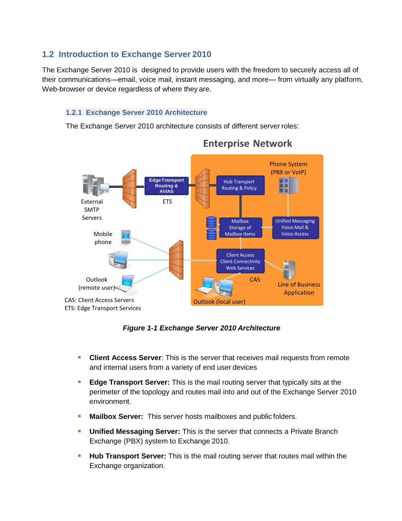
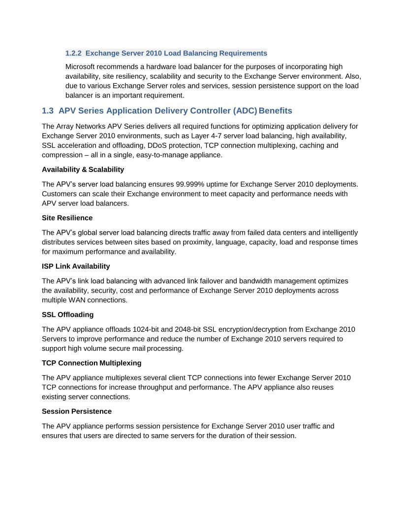
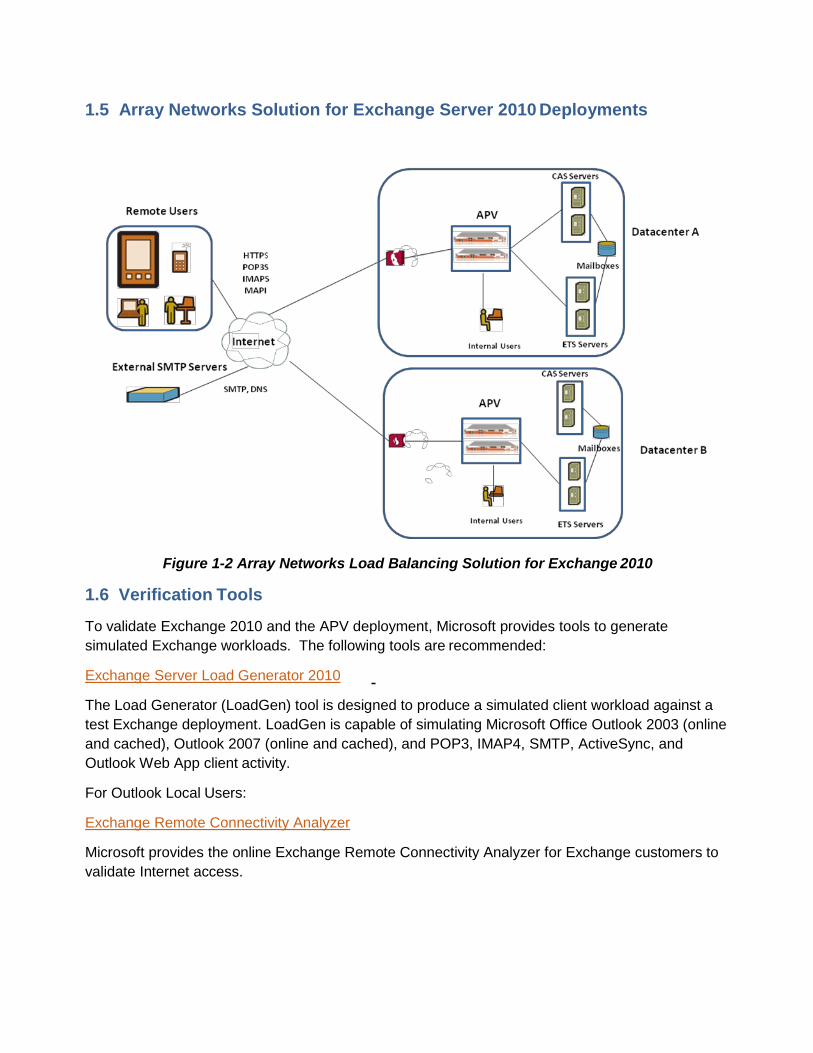
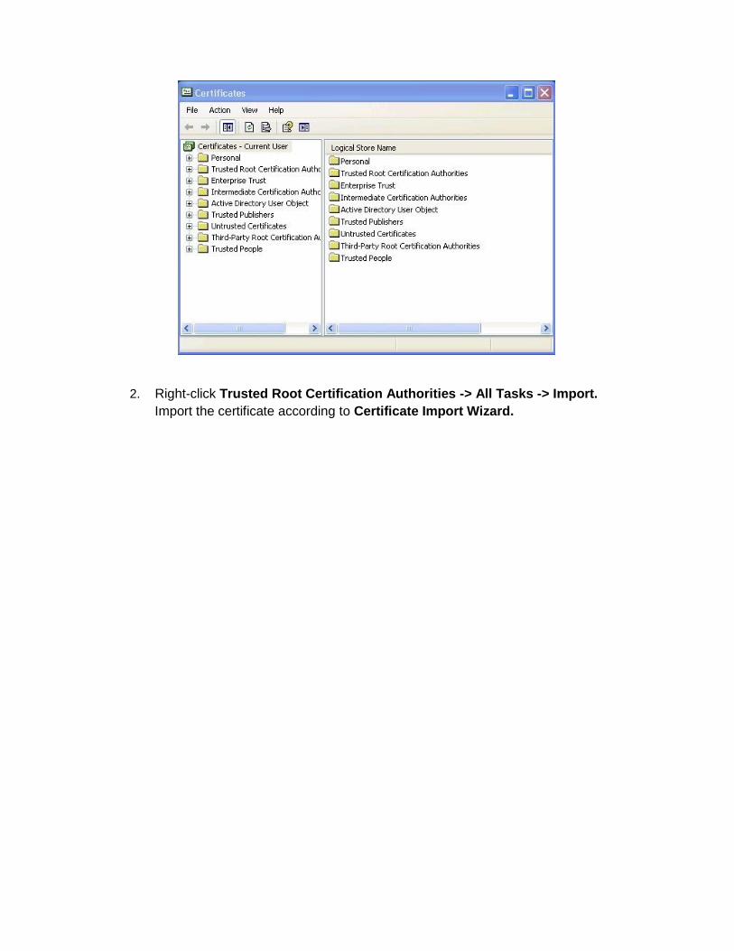
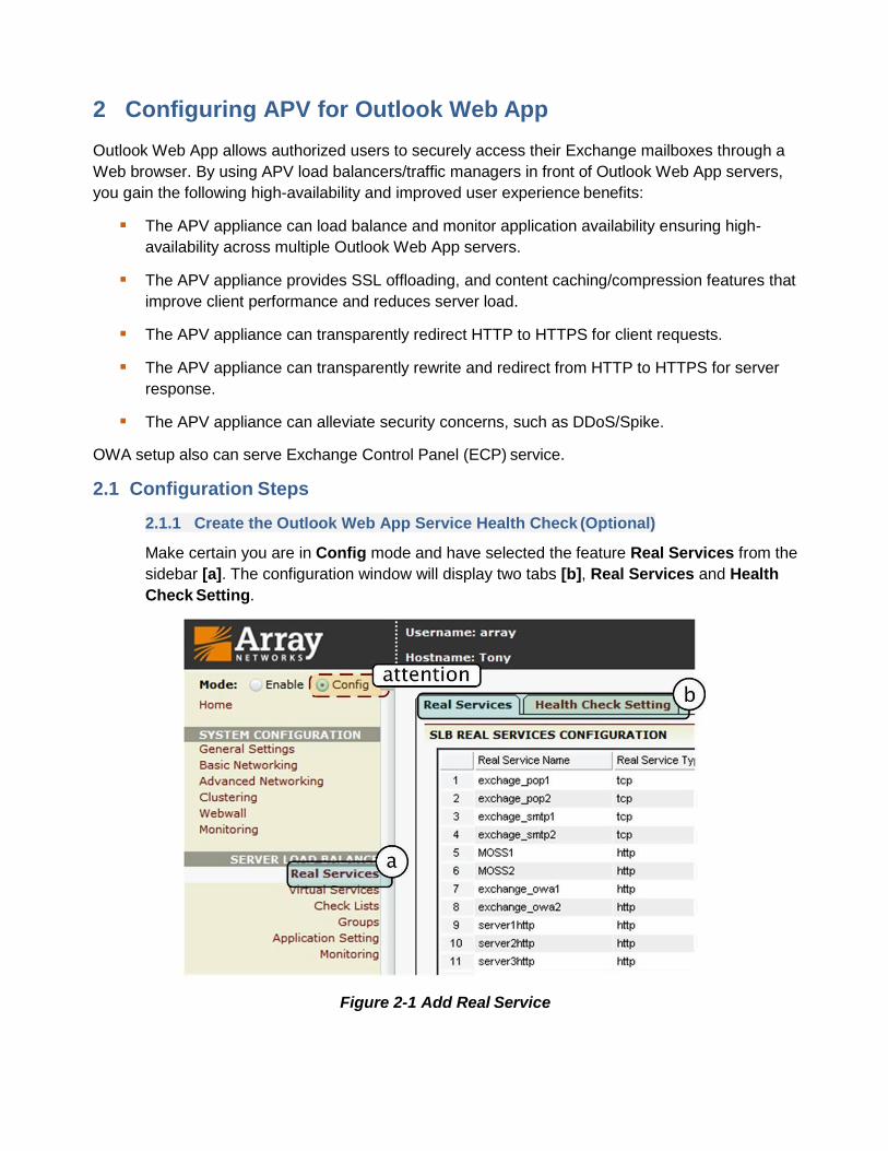
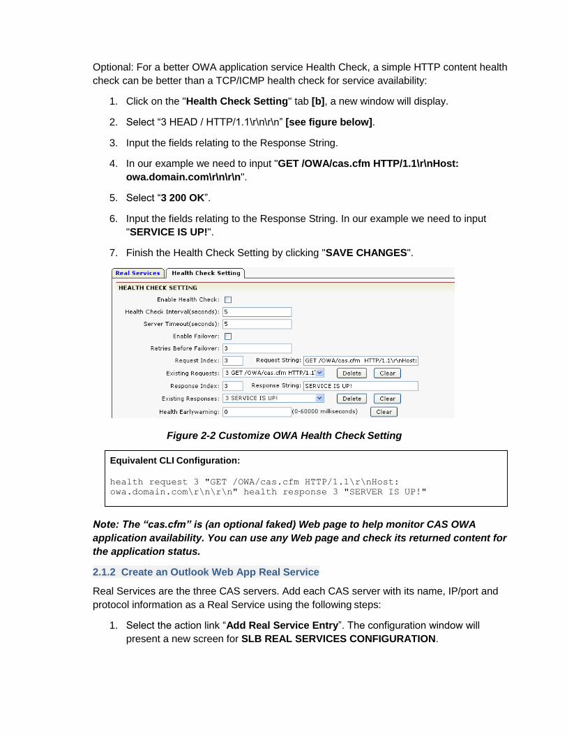
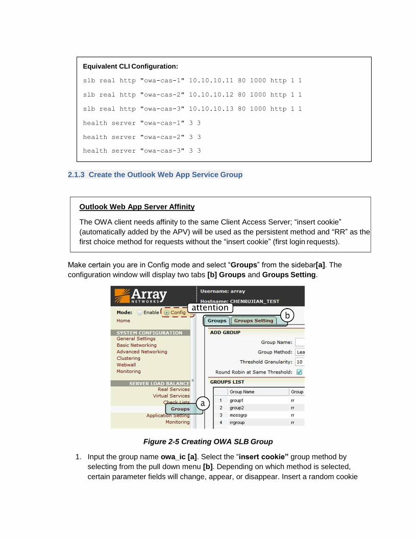
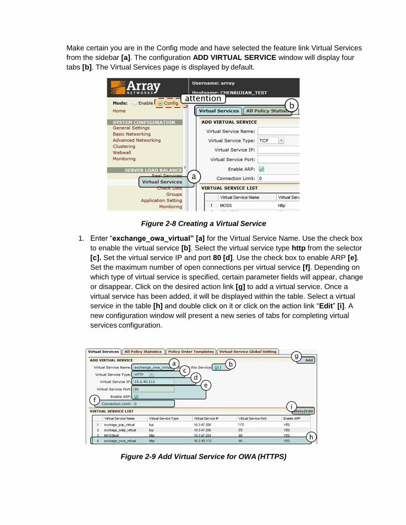
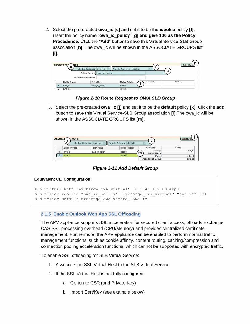
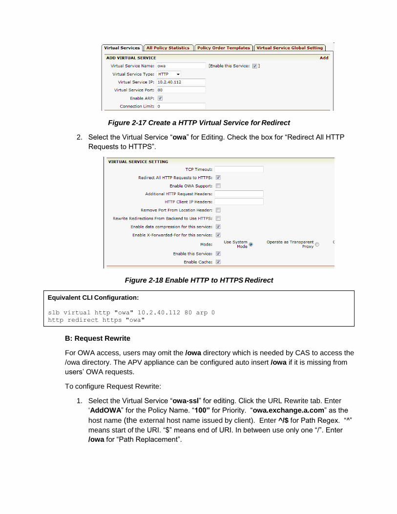
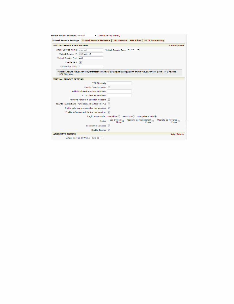
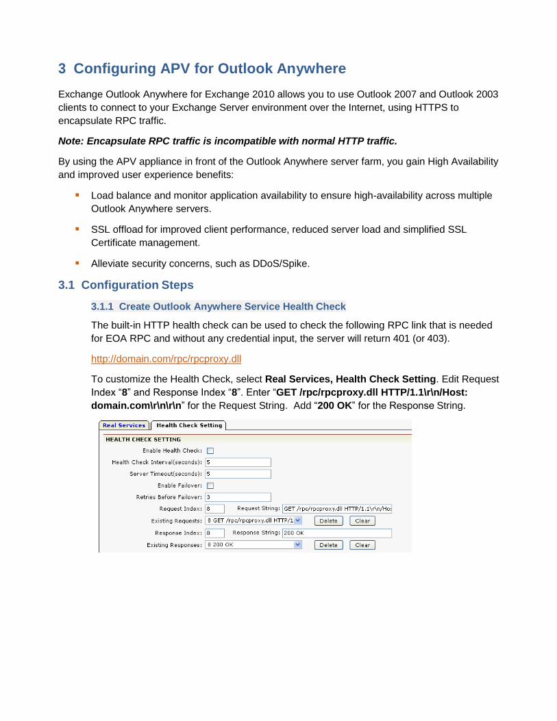
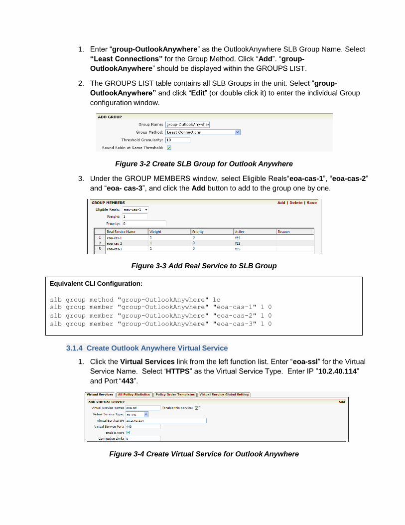
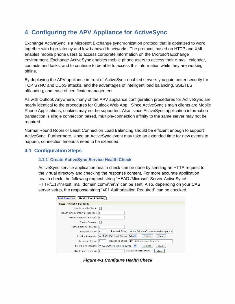
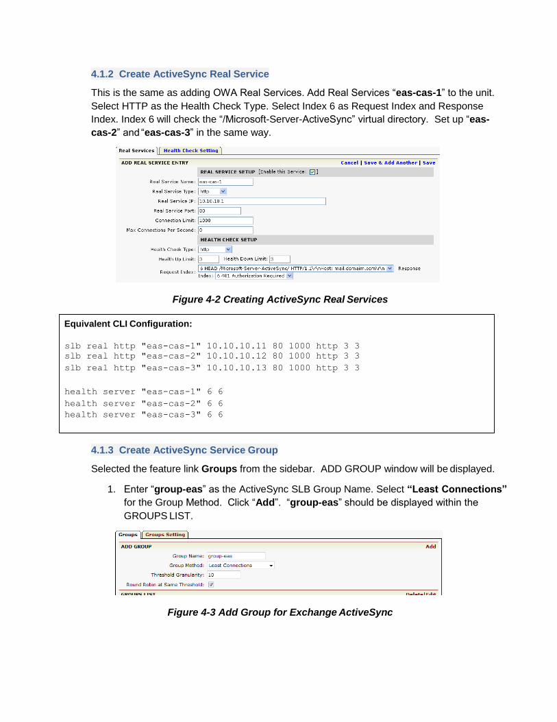
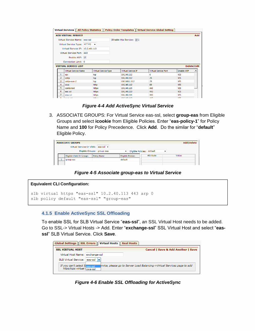
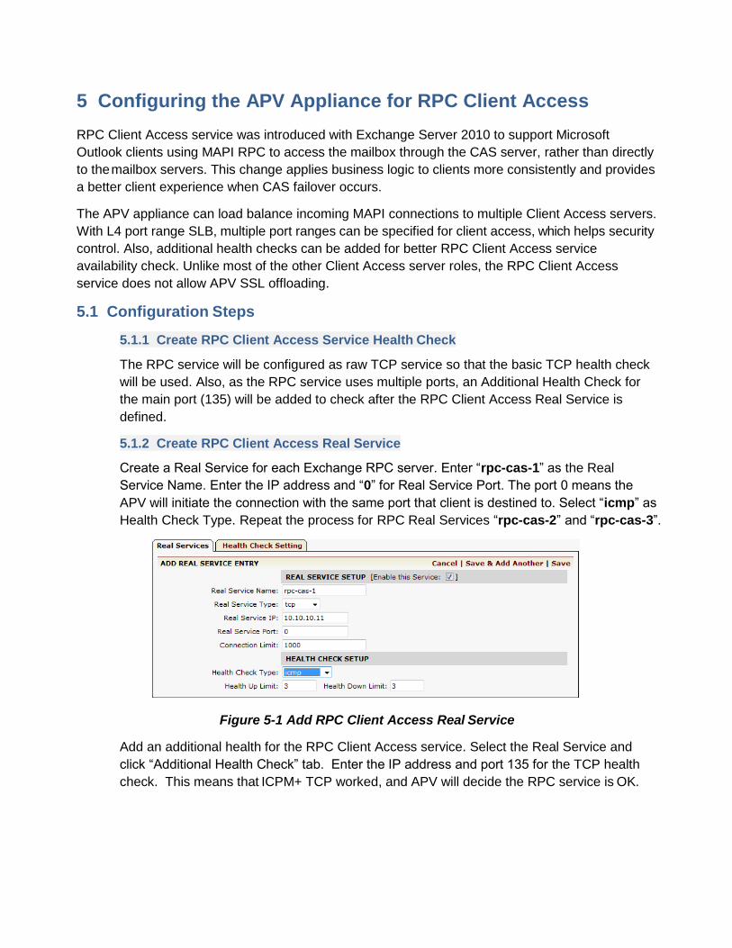
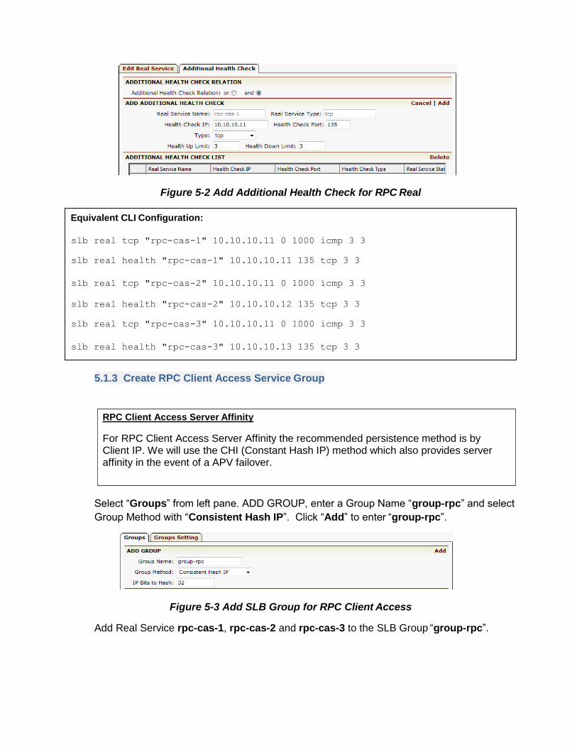
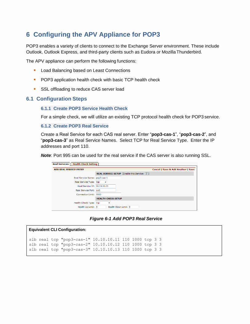
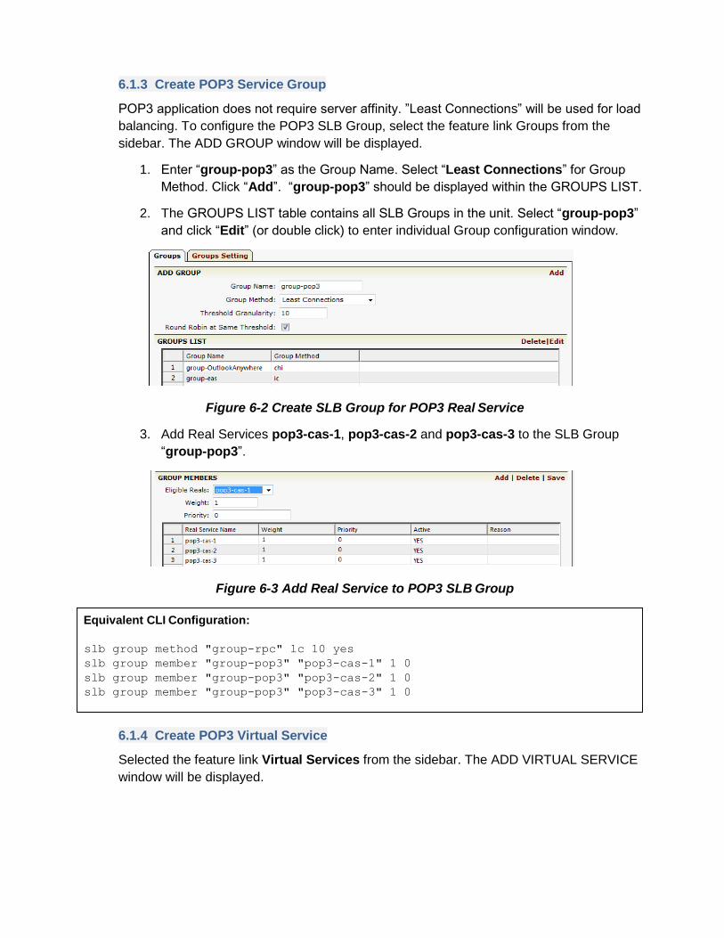

As the ―exchange-ssl SSL Virtual Host already has its KeyCertificate imported and is
Enabled (running) no other setup is needed Clients will now be able to access pop3-ssl
Virtual Service
Equivalent CLI Configuration
ssl host virtual exchange-ssl pop3-ssl
7 Configuring the APV Appliance for IMAP4
IMAP4 enables a variety of clients to connect to the Exchange Server environment These include
Outlook Outlook Express and third-party clients such as Eudora or Mozilla Thunderbird
The APV appliance can perform the following functions
Load Balancing based on Least Connections
IMAP application health check with basic TCP health check
SSL offloading (optional)
71 Configuration Steps
711 Create IMAP4 Service Health Check
The default basic TCP protocol health check will be used for this example Based on Client
Access Server setup an Additional Health Check andor Script Application Health Check
can be added for more reliable application availability check
712 Create IMAP4 Real Service
Follow the same instructions that were used to add OWA Real Services to add IMAP Real
Services on CAS We give different Real Service names as ―imap-cas-1 ―imap-cas-2 and
―imap-cas-3 The protocol is TCP and the port address is 143
Figure 7-1 Create Real Service for IMAP4
Equivalent CLI Configuration
slb real tcp imap-cas-1 10101011 143 1000 tcp 3 3
slb real tcp imap-cas-2 10101012 143 1000 tcp 3 3
slb real tcp imap-cas-3 10101013 143 1000 tcp 3 3
713 Create IMAP4 Service Group
IMAP application does not require server affinity Least Connections can be used for load
balancing To configure the IMAP SLB Group select the feature link Groups from the
sidebar The ADD GROUP window will be displayed
1 Enter ―group-imap as the Group Name Select ―Least Connections for the Group
Method Click ―Add ―group-imap should be displayed within the GROUPS LIST
2 The GROUPS LIST table contains all SLB Groups in the unit Select ―group-imap
and click ―Edit (or double click) to enter individual Group configuration window
Figure 7-2 Create SLB Group for IMAP4
3 For GROUP MEMBERS add Real Service imap-cas-1 imap-cas-2 and imap-cas-3
to the SLB Group ―group-imap
Figure 7-3 Add Real Service to IMAP SLB Group
714 Create Secures IMAP4 Virtual Service
Select the feature link Virtual Services from the sidebar The ADD VIRTUAL SERVICE
window will be displayed
Equivalent CLI Configuration
slb group method group-imap lc 10 yes
slb group member group-imap imap-cas-1 1 0
slb group member group-imap imap-cas-2 1 0
slb group member group-imap imap-cas-3 1 0
1 Enter ―imap4-ssl for the Virtual Service Name Select TCP for the Virtual Service
Type Enter Virtual Service IP ―1024012 and Port ―993 Click Add ―imap4-ssl
will be displayed within the VIRTUAL SERVICE LIST table
2 The VIRTUAL SERVICE LIST table contains Virtual Services in the unit Select
―imap4-ssl and click ―Edit (or double click) to enter the individual Virtual Service
configuration window
Figure 7-4 Creating Virtual Service for IMAP4
3 Select ―group-imap for Eligible Vlink or Groups and default for Eligible Policies
Figure 7-5 Associate SLB Group to IMAP Virtual Service
715 Enable IMAP4 SSL Offloading
To enable SSL for SLB Virtual Service ―imap4-ssl an SSL Virtual Host needs to be added
Go to SSL-gt Virtual Hosts -gt Add Enter ―exchange-ssl SSL Virtual Host and select the
―imap4-ssl SLB Virtual Service Click Save
Figure 7-5 Add SSL Virtual Host for IMAP4 Secured Access
Equivalent CLI Configuration
slb virtual tcp imap4-ssl 1024012 993 arp 0
slb policy default imap4 group-imap
As the ―exchange-ssl SSL Virtual Host already has its KeyCertificate imported and is
Enabled (running) no other setup is needed Clients will now be able to access the imap4-
ssl Virtual Service
Equivalent CLI Configuration
ssl host virtual exchange-ssl pop3-ssl
8 Configuring the APV Appliance for SMTP (Edge Transport)
In Microsoft Exchange Server 2010 the Edge Transport server role is deployed at organizations
perimeter network Designed to minimize the attack surface the Edge Transport server handles all
Internet-facing mail flow which provides SMTP relay and smart host services for the Exchange
environment Additional layers of message protection and security are provided by a series of
agents that run on the Edge Transport server and act on messages as they are processed by the
message transport components These agents support the features that provide protection against
viruses and spam and apply transport rules to control message flow
The APV appliance can spread the load among Edge Transport Servers and detect failure for
SMTP high availability
Also the APV appliance can provide TLS (STARTTLS) offload to reduce CPU and memory usage
on CAS
81 Configuration Steps
Access WebUI make certain you are in ―Config mode The left side of the screen is selectable
feature links
811 Create SMTP (Edge Transport) Service Health Check
The default basic TCP protocol health check will be used for the example Based on the
Edge Transport Server setup an Additional Health Check andor Script Application Health
Check can be added for more reliable application availability checking
812 Create SMTP (Edge Transport) Real Service
Note SMTP Server Affinity is not required
Select the feature link Real Services from the sidebar
1 The default page is Real ServicesHealth Check Setting To create the Real
Service for SMTP click ldquoAdd Real Service Entryrdquo The ADD REAL SERVICE
ENTRY window will appear (See Figure 71)
Figure 8-1 Real ServicesHealth Check Setting
2 In the ADD REAL SERVICE ENTRY window enter ―mail-smtp1 for the Real
Service Name Select ―tcp as the Real Service Type Enter the Real Service IP and
Port (25 for SMTP) Click ―Save
Figure 8-2 Create Real Service for SMTP
3 Repeat the process for ―mail-smtp2
813 Create SMTP (Edge Transport) Service Group
Selected the feature link Groups from the sidebar The ADD GROUP window will be
displayed
1 Enter ―group-smtp-et for the Edge Proxy Group Name Select ldquoConsistent Hash
IP for the Group Method Click ―Add ―group-smtp-et should be displayed within
the GROUPS LIST
2 The GROUPS LIST table contains all SLB Groups in the unit Select ―group-smtp-etrdquo
and click ―Edit (or double click) to enter the individual Group configuration window
Figure 8-3 Create Service Group for SMTP
3 GROUP MEMBERS select ―mail-smtp1 and ―mail-smtp2 from Eligible Reals to
Add to the group and click ―Save
Equivalent CLI Configuration
slb real tcp ldquomail-smtp1rdquo 10102011 25 1000 tcp 1 3
slb real tcp ldquomail-smtp2rdquo 10102012 25 1000 tcp 1 3
Figure 8-4 Add Group Member to SMTP Group
814 Create SMTP (Edge Transport) Virtual Service
Select the feature link Virtual Services from the sidebar The ADD VIRTUAL SERVICE
window will be displayed
1 Enter ―smtp for the Virtual Service Name Select TCP for the Virtual Service Type
Enter Virtual Service IP ―1024012 and Port ―25 (SMTP) Click Add ―smtp will be
displayed within the VIRTUAL SERVICE LIST table
2 The VIRTUAL SERVICE LIST table contains Virtual Services in the unit Select
―smtp and click ―Edit (or double click it) to enter the individual Virtual Service
configuration window
Figure 8-5 Add Virtual Service for SMTP
3 VIRTUAL SERVICE SETTING Select ―Operate as Transparent Proxy For
Transparent Proxy the client IP will be used to make the TCP connection to Edge
Transport servers so that Edge Transport servers may use the client IP for its policies
(such as for whiteblack list)
4 ASSOCIATE GROUPS Select group-smtp-et from Eligible Groups and select
default from Eligible Policies Click Add button to enter The group-smtp-et will be
displayed within the ASSOCIATE GROUPS list
Equivalent CLI Configuration
slb group method ldquogroup-smtprdquo chi 32
slb group member ldquogroup-smtprdquo ldquomail-smtp1rdquo
slb group member ldquogroup-smtprdquo ldquomail-smtp2rdquo
Figure 8-6 Virtual Service Setting for SMTP
815 Enable SMTP (Edge Transport) SSL Offloading
The APV appliance can be configured to provide SMTP TLS (STARTTLS) access For the
SMTP TLS Virtual Service the Virtual Service Type will be TCPS and can be port 25 or an
unused port
816 Misc SMTP Outbound Support
To enable internal SMTP servers to transport emails to other Internet SMTP email servers
NATing will need to be setup on the APV
Select the Advanced Networking feature tab click Add NAT Port
Figure 8-7 Add NAT Port
Equivalent CLI Configuration
slb virtual tcp smtp 10240112 25 arp 0
slb policy default smtp group-smtp-et
system mode transparent smtp
Equivalent CLI Configuration
nat port 10240112 1010208 255255255248 60 10211
9 Configuring the APV Appliance for Link Redundancy Using
LLB
To increase the bandwidth and improve application access availability should the ISPWAN link go
down a second ISPWAN link is recommended
Array APV Link Load Balancing (LLB) is an integrated feature that manages multiple ISPWAN links
through link health check for automatically failover policy-based routing and link load balancing
To utilize multiple ISPWAN links multiple Virtual Services (redundant) need to be added to
facilitate client access through different links (ISP IP) for Exchange 2010 and each IP can be
added to the DNS as a different DNS A Record for the same domain name
Record FQDN Record Type
Record Value owadomaincom A 10240112
owadomaincom A 1921681112
SMTP redundancy is built-in with DNS multiple MX records Multiple MX records for a domain can
be added to a DNS server Each MX record can be assigned with preference
Record FQDN Record Type Record Value MX Pref
domaincom MX mail1domaincom 10 domaincom MX mail2domaicom 20
mail1domaincom A 10240112
mail2domaincom A 1921681112
For outbound email the APV appliancelsquos policy-based routing can be used to speed up mail
delivery for specific targets and failover when needed
Following are configuration steps for how to setup multiple link (multi-home) access for the
Exchange 2010 mail service
91 Configuration Steps
911 Add additional port for WAN-2 access
Config -gt Basic Networking -gt Port
To make port 2 usable for the second WAN link select ―port2 and enter static IP
―192168121 and Static Mask 2552552550
Figure 9-1 Add addition interface for WAN 2
912 Add Duplicate Virtual Service for WAN 2 access
This setup is the same as previous examples to create SLB Virtual Services In this example
we add Virtual Services smtp-wan-2 impa4-ssl-wan2 pop3-ssl-wan2 and owa-ssl-wan2
Figure 9-2 List of redundant SLB Virtual Service
The new SLB Virtual Services added for ―wan-2 use the same SLB group as the other
Virtual Services for WAN 1
Figure 9-3 owa-ssl (WAN-1)
Figure 9-4 owa-ssl-wan2 (WAN-2)
913 Create LLB Links information
Navigate to Link Load Balance -gt OutBound Settings -gt Add
Enter a unique name ―wan-1 for the Link Name Enter IP address ―10211 as the gateway
IP address (external router IP address) of this LLB link Enter ―102111 as the Health
check destination IP LLB health check will continuously send ICMP requests to the
assigned Health Check destination IP address via the link ―wan-1 Enter ―10 for the
Interval This is the time interval of the LLB health check Enter ―1 for the Weight of the
Link (optional) Assign ―10240111 as the Health Check source IP This is the IP address
assigned as the source IP of the LLB health check IP Click ―Save
Figure 9-5 Create LLB Link
For WAN link 2 enter a unique name ―wan-2 for the Link Name IP address ―192168111
Enter ―12121212 as the Health check destination IP (as an example) Enter ―10 for the
Interval (default) Enter ―1 for the Weight (default) and click ―Save
Figure 9-6 LLB Link Information
914 Create LLB DNS record for inbound traffic
Navigate to Link Load Balance -gt Inbound Settings -gt Add
The ADD DNS ENTRY window will appear Enter ―owadomaincom for the Host Name
and IP address ―10240115 (this is the IP of the A record) and Port ―443 This is the same
as the SLB Virtual Servicelsquos ―owa-ssl IP and Port and will accessed through the ―wan-1
link Enter ―1 for the Weight (default) Click ―Save
Figure 9-7 Create domain name and Service IP
Based on the IP and Port entered LLB will try to match a local SLB VirtualReal Service
configured in LLB system If a match is found LLB will utilize the SLB health check status for
the VirtualReal Service as the corresponding IP status (UPDOWN) If there is no match
the IP configured is assumed to be ―UP (like normal DNS) LLB DNS only resolves the ―UP
IP to the client DNS queries
The name ―owadomaincom is the domain name that the user enters in their browser to
access the Outlook Web App
For link ―wan-2 enter ―owadomaincom for the host name IP address ―1921681115
and Port ―443 Enter ―1 for the Weight Click ―Save
Figure 9-8 Domain name and Service IP list
Equivalent CLI Configuration
llb link route wan-1 10211 102111 2 1
llb link route wan-2 192168111 12121212 10 1
Equivalent CLI Configuration
llb dns host owadomaincom 1921681115 1 443
llb dns host owadomaincom 10240112 1 443
llb dns ttl owadomaincom 60
10 Configuring the APV Appliance for Exchange 2010 Site
Resilience Using GSLB
Exchange 2010 may be deployed with a backup site in a separate geographic location with
mailbox data synchronized between the two sites and with the ability for one of the sites to take on
the entire load if the other fails Exchange 2010 uses database availability groups (DAGs) to keep
multiple copies of your mailboxes on different servers synchronized
Client Access DNS server
Backup Site
(Data Center)
Primary Site
HQ Office
Figure 10-1 Global Load Balancing for Exchange 2010
SMTP Servers
SLBLLBGSLB
SLBGSLB
POP3 IMAP SMTP POP3 IMAP SMTP
101 Fault Tolerance Configuration
If your mail server fails you are still able to receive incoming e-mail messages Most small to
medium sized companies will pay their ISPs a monthly fee for storage space on the ISPlsquos mail
servers For that to happen a new MX Record will need to be added to their DNS information
pointing to the ISPlsquos mail server with a higher priority For example
Record FQDN Record Type Record Value MX Pref
maildomainnet MX mail1domaincom 10 maildomainnet MX mail2domaincom 20
Normally clients from the Internet will access ―maildomaincom for mailbox access and the request
is sent to the Primary site In the event the Primary site is down the mail access switches
automatically to the Backup Site
Note Array GSLBSDNS supports BIND9 Named and zone file can be imported to APV for DNS
use The zone file can include MX records for client access
For non-SMTP clients or other Exchange Services clients may type ―owadomaincom for mailbox
access and initiate a regular DNS query for ―owadomaincom A record Normal DNS can resolve
―owadomaincom to HQ-link1-ip1 or round-robin with HQ-Link2-IP2 so that traffic will stay on the
Primary Site If one link is down approximately 50 of access will need to be restarted as normal
DNS does not care if the Link or Primary Site is down If the Primary Site is down to switch to the
Backup Site the client needs to type a different name such as ―owa2domaincom to access the
backup site to continue to access the email service
With Array GSLBSmartDNS if HQ-link1 (or HQ-link2) goes down the SmartDNS can resolve
―owadomailcom to the healthy IP and Exchange traffic will stay on the Primary Site Also once
both Primary Site links are down (or Exchange is downdisabled under maintenance) SmartDNS at
both sites or on the Data Center (backup site) can resolve ―owadomaincom to the Data Center IP
so that mail access can go through the Backup Site This will provide higher email serviceability and
a more user-friendly experience (requires only a single ―owadomailcom)
102 Configuration Steps
1021 Define GSLBSDNS Members
GSLBSDNS Members are typically APVs that exchange status with other SDNS members
in a GSLBSDNS network To create an SDNS Member from the WebUI
Navigate to Global Load Balance -gt General Settings -gt Add Member Entry
Type ―HQ-APV1 for the Name select ―all for the Type Enter ―10240111 for the IP
address and ―5888 as the Port Click Save amp Add Another to add more ―DC-APV1
members
Figure 10-2 Create SDNS Member
From SDNS MEMBER SETTING check the Local Member radius button to assign the
member as the Local Member
Figure 10-3 SDNS Member List
1022 Creating GSLB Records
To add domain name A Records for SDNS to manage
Navigate to Global Load Balance -gt Records
Enter ―pop3domaincom for the Domain Name and type in the IPport information Or
select the Virtual Service or Real Service from the available list Click Save
Note SDNS Member Type can be
Proxy serve with SLB function report VIPRIP health and load to SDNS members
DNS serve with DNS server
All Proxy + DNS
Figure 10-4 Create A Record
Figure 10-5 List of A-Records
1023 GSLBSDNS Disaster Recovery Site Location
Site Location for Disaster Recovery is collection of members A GSLBSDNS network can
contain multiple sites To create a Site Location navigate to
Global Load Balance -gt Topology -gt Site (Default) -gt Add Site Entry
Enter ―Primary-HQ as the given Site and ―100 for Weight Click Save amp Add Another to
add the ―Backup-DC
Figure 10-6 Create a SDNS Site
To add members to the selected site
Select the ―Primary-HQ site by clicking View Click Edit Members of the Site and the
SDNS SITElsquoS (Member) LIST window will display
Figure 10-7 Edit Members of the Site
Under SDNS SITElsquoS (Member) LIST windows check the ―Is Site Member box for members
belonging to the ―Primary-HQ site Click Save
Figure 10-8
1024 Creating a DR Group with DNS domain name
Navigate to Global Load Balance -gt Topology -gt DR Group
Type ―mail-pop3 for the Group Name (any unique name) and ―pop3domaincom for the
Domain Name The Domain name is the name that clients use to access the service Click
Add DR Group Enter all domain names that will be supported by the DR site
Figure 10-9 Add DR Group
Array GSLBSDNS Disaster Recovery supports two Site Groups - ―Primary and ―Standby
To assign sites to Primary Site Group
1 For Service Group Name mail-pop3 check the ―View Sites radio button All
available ―Sites should show that serve the Group
2 Select the ―Primary from Select GroupSiteView Check the To Current Group box
for the Primary- HQ Site Click Save Group Site Setting
3 Select the ―Backup from Select GroupSiteView Check the To Current Group box
for the Backup- DC Site Click Save Group Site Setting
4 Repeat steps 1 2 and 3 for service groups mail-imap and mail-owa
Figure 10-10 Assign DR Sites to the Service Group
You need to do a similar setup for SDNS members on the backup site
1025 Setup GSLBSDNS with BIND 9
The APV GSLBSDNS includes standard BIND9 (named) functionalities You may import
the standard ―namedconf and individual zone files onto the APV to support full DNS
functions Other than DNS A records all other DNS records are supported by BIND9 For
example to make GSLBSDNS support MX record resolution the MX records for a domain
need to be added to the normal domain zone file and then import the zone file
To import select Global Load Balance -gt Records -gt Others You can hit ―Browse to
select local files for input to the APV
Figure 10-11 Importing the Zone File
Once the BIND 9 Configure file andor selected zone files are imported click Restart to
restart LocalDNS service to enable the changes
1026 GSLBSDNS DR Deployment Verification
To validate that the APV GSLBSDNS can correctly resolve DNS queries for DNS A and MS
records Windows command tool ―nslookup can be used On the Windows command line
type ―nslookup to enter the nslookup utility Type ―server 10240111 to set the APV as
the DNS server and ―set q=a (for Query DNS A Record)
Type the domain names that are managed by Array GSLBSDNS ndash See the following
For the Primary-HQ site it is dual homed to ―owadomaincom so that two addresses
(10240111 and 1921681115) are returned in round-robin term The second IP can be
disabled if the Link is down or the Virtual Service is disabled (considered down)
To test the MX record support enter the ―nslookup utility set the APV as the default DNS
server Type ―set q=mx to set the default DNS query type to MX record and type the
domain name The APV GSLBSDNS BIND9 will resolve it See the following
1027 Log Information
On the APV appliance each DNS query can be logged with INFO level as the following
Primary Site Configuration Summary
link load balancing DNS configuration llb dns host owadomaincom 1921681115 1 443 llb dns host owadomaincom 10240112 200 443 llb dns host pop3domaincom 1921681112 1 995 llb dns host pop3domaincom 10240112 200 995 llb dns host imapdomaincom 1921681112 1 993 llb dns host imapdomaincom 10240112 200 993 llb dns ttl owadomaincom 60 llb dns ttl pop3domaincom 60 llb dns ttl imapdomaincom 60
smart DNS configuration sdns on Check sdns member attribute HQ-APV1 10240111 5888 all sdns member attribute DC-APV1 19216840111 5888 all sdns member local HQ-APV1 1000 sdns interval heartbeat 2 sdns site location Backup-DC 100 sdns site location Primary-HQ 100 sdns site member Primary-HQ HQ-APV1 sdns group dr mail-pop3 pop3domaincom sdns group preempt mail-pop3 1 sdns group primary mail-pop3 Primary-HQ sdns group standby mail-pop3 Backup-DC sdns group dr mail-imap imapdomaincom sdns group preempt mail-imap 1 sdns group primary mail-imap Primary-HQ sdns group standby mail-imap Backup-DC sdns group dr mail-owa owadomaincom sdns group preempt mail-owa 1 sdns group primary mail-owa Primary-HQ sdns group standby mail-owa Backup-DC sdns group dr exchange2010 easdomaincom sdns group preempt exchange2010 1 sdns interval report 30 sdns dps interval send 120 sdns dps interval query 1200
INFO Apr 19 221623 The DNS request information LocalDNS-1011413 Request Domain
Name-pop3domaincom Request Type-A Request-success UpTime-20114192216
INFO Apr 19 221625 The DNS request information LocalDNS-1011413 Request Domain
Name-pop3domaincom Request Type-A Request-success UpTime-20114192216
Backup Site Configuration Summary
link load balancing DNS configuration llb dns host pop3domaincom 1071572 1 995 llb dns host imapdomaincom 1071572 1 993 llb dns host owadomaincom 1071572 1 443 llb dns ttl pop3domaincom 60 llb dns ttl imapdomaincom 60 llb dns ttl owadomaincom 60
smart DNS configuration sdns on Check sdns member attribute HQ-APV1 10240111 5888 all sdns member attribute DC-APV1 1071570 5888 all sdns member local DC-APV1 1000 sdns interval heartbeat 2 sdns site location Backup-DC 100 sdns site member Backup-DC DC-APV1 sdns site location Primary-HQ 100 sdns group dr mail-pop3 pop3domaincom sdns group preempt mail-pop3 1 sdns group primary mail-pop3 Primary-HQ sdns group standby mail-pop3 Backup-DC sdns group dr mail-imap imapdomaincom sdns group preempt mail-imap 1 sdns group primary mail-imap Primary-HQ sdns group standby mail-imap Backup-DC sdns group dr mail-owa owadomaincom sdns group preempt mail-owa 1 sdns group primary mail-owa Primary-HQ sdns group standby mail-owa Backup-DC sdns interval report 30 sdns dps interval send 120 sdns dps interval query 1200
sdns dps history 9000 sdns dps expire 1 sdns dps method rtt sdns dps off sdns dps master off NoCheck IP Address sdns snmp interval 300 sdns snmp version v2c sdns statistics on all sdns statistics on localdns sdns persistent timeout 3600 sdns recursion off
sdns dps history 9000 sdns dps expire 1 sdns dps method rtt sdns dps off sdns dps master off NoCheck IP Address sdns snmp interval 300 sdns snmp version v2c sdns statistics on all sdns statistics on localdns sdns persistent timeout 3600 sdns recursion off
11 Summary
APV Application Delivery Controllers deliver all required application delivery functions for optimizing
Exchange Server 2010 environments such as Layer 4-7 server load balancing link load balancing
high availabilityDR SSL acceleration and offloading Session Persistence TCP connection
multiplexing caching and compression ndash all in a single easy-to-manage appliance
Arraylsquos APV Application Delivery Controllers enhance the availability performance and security
characteristics of Microsoft Exchange 2010 solution
Appendix I
The following describes the mail configurations on the client
1 Go to Start -gt Control Panel -gt Mail The following dialog box is displayed
2 Select Prompt for a profile to be used and click Add Enter ―oa_TMrdquo in the displayed
dialog box as shown in the following figure
3 Click OK on the New Profile dialog box and OK on the Mail dialog box The following dialog
box is displayed
4 Select Manually configure server settings or additional server types Click Next The
following dialog box is displayed
5 Select Microsoft Exchange or compatible service Click Next On the displayed dialog
box enter ―MAIL-01exhange2010com as the Server and ―array as User Name and
select Use Cached Exchange Mode as shown in the following figure
6 Click Check Name to make sure that the user name is valid Then click More Settings
The following dialog box is displayed
7 Select Connect using my Local Area Network (LAN) and Connect to Microsoft
Exchange using HTTP Click Exchange Proxy Settings Click OK The following dialog
box is displayed
8 Enter ―mailexchange2010com for http Select On fast networks connect using
HTTP first then connect using TCPIP and On slow networks connect using HTTP
first then connect using TCPIP Click OK The following dialog box is displayed
9 Enter your user name and password Click OK The following dialog box is displayed
10 Click Finish
This completes the mail configurations on the client
Note When using Outlook for access select the oa_TM profile on the
startup of Outlook
1
About Array Networks
Array Networks is a global leader in application delivery networking with over 5000 worldwide customer deployments Powered by award-winning SpeedCore software Array application delivery WAN optimization and secure access solutions are recognized by leading enterprise service provider and public sector organizations for unmatched performance and total value of ownership Array is headquartered in Silicon Valley is backed by over 400 employees worldwide and is a profitable company with strong investors management and revenue growth Poised to capitalize on explosive growth in the areas of mobile and cloud computing analysts and thought leaders including Deloitte IDC and Frost amp Sullivan have recognized Array Networks for its technical innovation operational excellence and market opportunity
copy2016 Array Networks Inc All rights reserved Array Networks the Array Networks logo and ArrayOS are all trademarks of Array Networks Inc in the United States and other countries All other trademarks service marks registered marks or registered service marks are the property of their respective owners Array Networks assumes no responsibility for any inaccuracies in this document Array Networks reserves the right to change modify transfer or otherwise revise this publication without notice
To purchase
Array Networks
Solutions please
contact your
Array Networks
representative at
1-866-MY-ARRAY
(692-7729) or
authorized reseller
Jan-2016 rev1 a
Corporate Headquarters infoarraynetworkscom 408-240-8700 1 866 MY-ARRAY wwwarraynetworkscom EMEA rschmitarraynetworkscom +32 2 6336382
China supportarraynetworkscomcn +010-84446688 France and North Africa infosfrancearraynetworkscom +33 6 07 511 868
India isalesarraynetworkscom +91-080-41329296 Japan sales-japan arraynetworkscom +81-45-664-6116
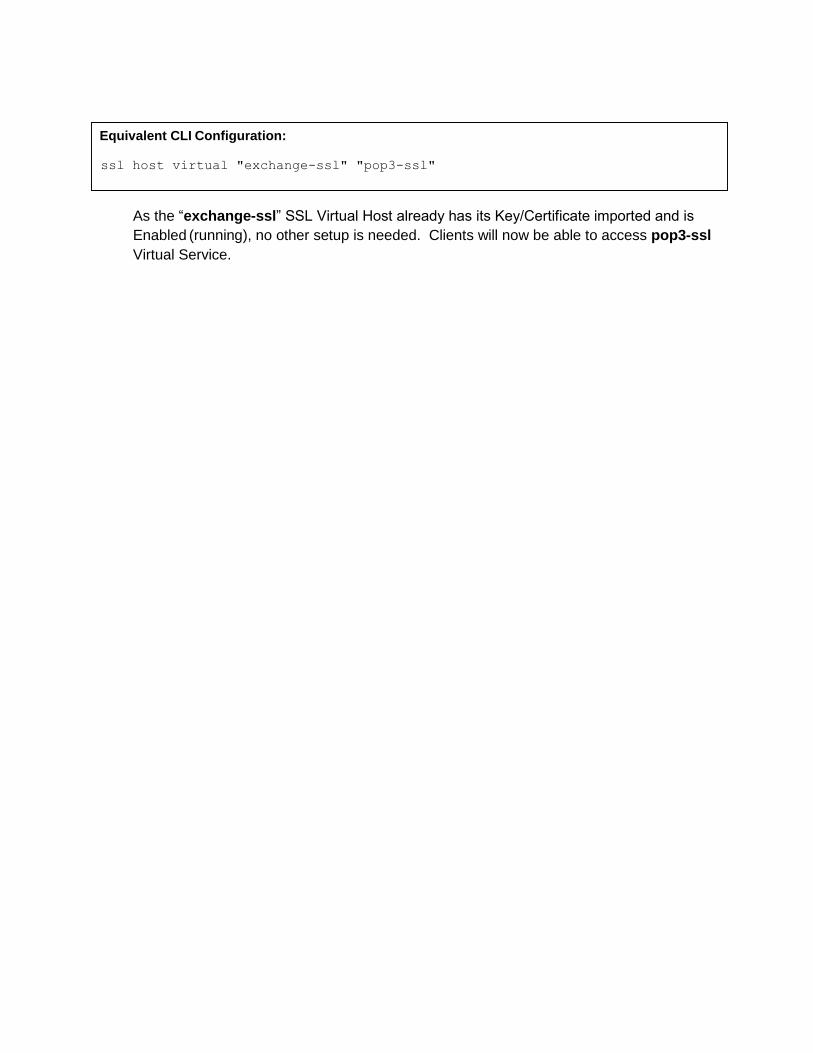
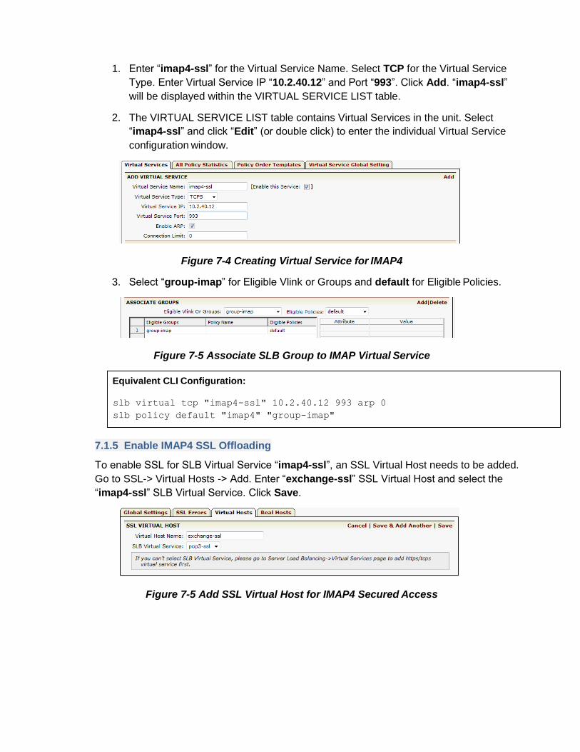
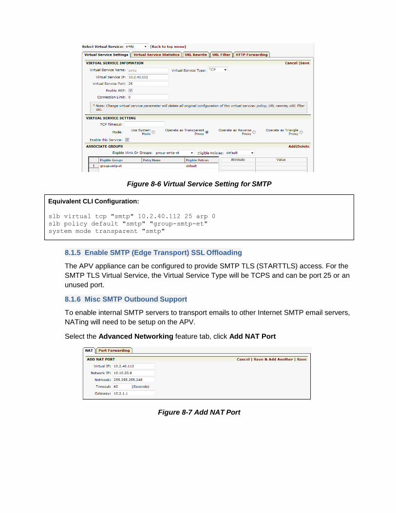
Equivalent CLI Configuration
nat port 10240112 1010208 255255255248 60 10211
9 Configuring the APV Appliance for Link Redundancy Using
LLB
To increase the bandwidth and improve application access availability should the ISPWAN link go
down a second ISPWAN link is recommended
Array APV Link Load Balancing (LLB) is an integrated feature that manages multiple ISPWAN links
through link health check for automatically failover policy-based routing and link load balancing
To utilize multiple ISPWAN links multiple Virtual Services (redundant) need to be added to
facilitate client access through different links (ISP IP) for Exchange 2010 and each IP can be
added to the DNS as a different DNS A Record for the same domain name
Record FQDN Record Type
Record Value owadomaincom A 10240112
owadomaincom A 1921681112
SMTP redundancy is built-in with DNS multiple MX records Multiple MX records for a domain can
be added to a DNS server Each MX record can be assigned with preference
Record FQDN Record Type Record Value MX Pref
domaincom MX mail1domaincom 10 domaincom MX mail2domaicom 20
mail1domaincom A 10240112
mail2domaincom A 1921681112
For outbound email the APV appliancelsquos policy-based routing can be used to speed up mail
delivery for specific targets and failover when needed
Following are configuration steps for how to setup multiple link (multi-home) access for the
Exchange 2010 mail service
91 Configuration Steps
911 Add additional port for WAN-2 access
Config -gt Basic Networking -gt Port
To make port 2 usable for the second WAN link select ―port2 and enter static IP
―192168121 and Static Mask 2552552550
Figure 9-1 Add addition interface for WAN 2
912 Add Duplicate Virtual Service for WAN 2 access
This setup is the same as previous examples to create SLB Virtual Services In this example
we add Virtual Services smtp-wan-2 impa4-ssl-wan2 pop3-ssl-wan2 and owa-ssl-wan2
Figure 9-2 List of redundant SLB Virtual Service
The new SLB Virtual Services added for ―wan-2 use the same SLB group as the other
Virtual Services for WAN 1
Figure 9-3 owa-ssl (WAN-1)
Figure 9-4 owa-ssl-wan2 (WAN-2)
913 Create LLB Links information
Navigate to Link Load Balance -gt OutBound Settings -gt Add
Enter a unique name ―wan-1 for the Link Name Enter IP address ―10211 as the gateway
IP address (external router IP address) of this LLB link Enter ―102111 as the Health
check destination IP LLB health check will continuously send ICMP requests to the
assigned Health Check destination IP address via the link ―wan-1 Enter ―10 for the
Interval This is the time interval of the LLB health check Enter ―1 for the Weight of the
Link (optional) Assign ―10240111 as the Health Check source IP This is the IP address
assigned as the source IP of the LLB health check IP Click ―Save
Figure 9-5 Create LLB Link
For WAN link 2 enter a unique name ―wan-2 for the Link Name IP address ―192168111
Enter ―12121212 as the Health check destination IP (as an example) Enter ―10 for the
Interval (default) Enter ―1 for the Weight (default) and click ―Save
Figure 9-6 LLB Link Information
914 Create LLB DNS record for inbound traffic
Navigate to Link Load Balance -gt Inbound Settings -gt Add
The ADD DNS ENTRY window will appear Enter ―owadomaincom for the Host Name
and IP address ―10240115 (this is the IP of the A record) and Port ―443 This is the same
as the SLB Virtual Servicelsquos ―owa-ssl IP and Port and will accessed through the ―wan-1
link Enter ―1 for the Weight (default) Click ―Save
Figure 9-7 Create domain name and Service IP
Based on the IP and Port entered LLB will try to match a local SLB VirtualReal Service
configured in LLB system If a match is found LLB will utilize the SLB health check status for
the VirtualReal Service as the corresponding IP status (UPDOWN) If there is no match
the IP configured is assumed to be ―UP (like normal DNS) LLB DNS only resolves the ―UP
IP to the client DNS queries
The name ―owadomaincom is the domain name that the user enters in their browser to
access the Outlook Web App
For link ―wan-2 enter ―owadomaincom for the host name IP address ―1921681115
and Port ―443 Enter ―1 for the Weight Click ―Save
Figure 9-8 Domain name and Service IP list
Equivalent CLI Configuration
llb link route wan-1 10211 102111 2 1
llb link route wan-2 192168111 12121212 10 1
Equivalent CLI Configuration
llb dns host owadomaincom 1921681115 1 443
llb dns host owadomaincom 10240112 1 443
llb dns ttl owadomaincom 60
10 Configuring the APV Appliance for Exchange 2010 Site
Resilience Using GSLB
Exchange 2010 may be deployed with a backup site in a separate geographic location with
mailbox data synchronized between the two sites and with the ability for one of the sites to take on
the entire load if the other fails Exchange 2010 uses database availability groups (DAGs) to keep
multiple copies of your mailboxes on different servers synchronized
Client Access DNS server
Backup Site
(Data Center)
Primary Site
HQ Office
Figure 10-1 Global Load Balancing for Exchange 2010
SMTP Servers
SLBLLBGSLB
SLBGSLB
POP3 IMAP SMTP POP3 IMAP SMTP
101 Fault Tolerance Configuration
If your mail server fails you are still able to receive incoming e-mail messages Most small to
medium sized companies will pay their ISPs a monthly fee for storage space on the ISPlsquos mail
servers For that to happen a new MX Record will need to be added to their DNS information
pointing to the ISPlsquos mail server with a higher priority For example
Record FQDN Record Type Record Value MX Pref
maildomainnet MX mail1domaincom 10 maildomainnet MX mail2domaincom 20
Normally clients from the Internet will access ―maildomaincom for mailbox access and the request
is sent to the Primary site In the event the Primary site is down the mail access switches
automatically to the Backup Site
Note Array GSLBSDNS supports BIND9 Named and zone file can be imported to APV for DNS
use The zone file can include MX records for client access
For non-SMTP clients or other Exchange Services clients may type ―owadomaincom for mailbox
access and initiate a regular DNS query for ―owadomaincom A record Normal DNS can resolve
―owadomaincom to HQ-link1-ip1 or round-robin with HQ-Link2-IP2 so that traffic will stay on the
Primary Site If one link is down approximately 50 of access will need to be restarted as normal
DNS does not care if the Link or Primary Site is down If the Primary Site is down to switch to the
Backup Site the client needs to type a different name such as ―owa2domaincom to access the
backup site to continue to access the email service
With Array GSLBSmartDNS if HQ-link1 (or HQ-link2) goes down the SmartDNS can resolve
―owadomailcom to the healthy IP and Exchange traffic will stay on the Primary Site Also once
both Primary Site links are down (or Exchange is downdisabled under maintenance) SmartDNS at
both sites or on the Data Center (backup site) can resolve ―owadomaincom to the Data Center IP
so that mail access can go through the Backup Site This will provide higher email serviceability and
a more user-friendly experience (requires only a single ―owadomailcom)
102 Configuration Steps
1021 Define GSLBSDNS Members
GSLBSDNS Members are typically APVs that exchange status with other SDNS members
in a GSLBSDNS network To create an SDNS Member from the WebUI
Navigate to Global Load Balance -gt General Settings -gt Add Member Entry
Type ―HQ-APV1 for the Name select ―all for the Type Enter ―10240111 for the IP
address and ―5888 as the Port Click Save amp Add Another to add more ―DC-APV1
members
Figure 10-2 Create SDNS Member
From SDNS MEMBER SETTING check the Local Member radius button to assign the
member as the Local Member
Figure 10-3 SDNS Member List
1022 Creating GSLB Records
To add domain name A Records for SDNS to manage
Navigate to Global Load Balance -gt Records
Enter ―pop3domaincom for the Domain Name and type in the IPport information Or
select the Virtual Service or Real Service from the available list Click Save
Note SDNS Member Type can be
Proxy serve with SLB function report VIPRIP health and load to SDNS members
DNS serve with DNS server
All Proxy + DNS
Figure 10-4 Create A Record
Figure 10-5 List of A-Records
1023 GSLBSDNS Disaster Recovery Site Location
Site Location for Disaster Recovery is collection of members A GSLBSDNS network can
contain multiple sites To create a Site Location navigate to
Global Load Balance -gt Topology -gt Site (Default) -gt Add Site Entry
Enter ―Primary-HQ as the given Site and ―100 for Weight Click Save amp Add Another to
add the ―Backup-DC
Figure 10-6 Create a SDNS Site
To add members to the selected site
Select the ―Primary-HQ site by clicking View Click Edit Members of the Site and the
SDNS SITElsquoS (Member) LIST window will display
Figure 10-7 Edit Members of the Site
Under SDNS SITElsquoS (Member) LIST windows check the ―Is Site Member box for members
belonging to the ―Primary-HQ site Click Save
Figure 10-8
1024 Creating a DR Group with DNS domain name
Navigate to Global Load Balance -gt Topology -gt DR Group
Type ―mail-pop3 for the Group Name (any unique name) and ―pop3domaincom for the
Domain Name The Domain name is the name that clients use to access the service Click
Add DR Group Enter all domain names that will be supported by the DR site
Figure 10-9 Add DR Group
Array GSLBSDNS Disaster Recovery supports two Site Groups - ―Primary and ―Standby
To assign sites to Primary Site Group
1 For Service Group Name mail-pop3 check the ―View Sites radio button All
available ―Sites should show that serve the Group
2 Select the ―Primary from Select GroupSiteView Check the To Current Group box
for the Primary- HQ Site Click Save Group Site Setting
3 Select the ―Backup from Select GroupSiteView Check the To Current Group box
for the Backup- DC Site Click Save Group Site Setting
4 Repeat steps 1 2 and 3 for service groups mail-imap and mail-owa
Figure 10-10 Assign DR Sites to the Service Group
You need to do a similar setup for SDNS members on the backup site
1025 Setup GSLBSDNS with BIND 9
The APV GSLBSDNS includes standard BIND9 (named) functionalities You may import
the standard ―namedconf and individual zone files onto the APV to support full DNS
functions Other than DNS A records all other DNS records are supported by BIND9 For
example to make GSLBSDNS support MX record resolution the MX records for a domain
need to be added to the normal domain zone file and then import the zone file
To import select Global Load Balance -gt Records -gt Others You can hit ―Browse to
select local files for input to the APV
Figure 10-11 Importing the Zone File
Once the BIND 9 Configure file andor selected zone files are imported click Restart to
restart LocalDNS service to enable the changes
1026 GSLBSDNS DR Deployment Verification
To validate that the APV GSLBSDNS can correctly resolve DNS queries for DNS A and MS
records Windows command tool ―nslookup can be used On the Windows command line
type ―nslookup to enter the nslookup utility Type ―server 10240111 to set the APV as
the DNS server and ―set q=a (for Query DNS A Record)
Type the domain names that are managed by Array GSLBSDNS ndash See the following
For the Primary-HQ site it is dual homed to ―owadomaincom so that two addresses
(10240111 and 1921681115) are returned in round-robin term The second IP can be
disabled if the Link is down or the Virtual Service is disabled (considered down)
To test the MX record support enter the ―nslookup utility set the APV as the default DNS
server Type ―set q=mx to set the default DNS query type to MX record and type the
domain name The APV GSLBSDNS BIND9 will resolve it See the following
1027 Log Information
On the APV appliance each DNS query can be logged with INFO level as the following
Primary Site Configuration Summary
link load balancing DNS configuration llb dns host owadomaincom 1921681115 1 443 llb dns host owadomaincom 10240112 200 443 llb dns host pop3domaincom 1921681112 1 995 llb dns host pop3domaincom 10240112 200 995 llb dns host imapdomaincom 1921681112 1 993 llb dns host imapdomaincom 10240112 200 993 llb dns ttl owadomaincom 60 llb dns ttl pop3domaincom 60 llb dns ttl imapdomaincom 60
smart DNS configuration sdns on Check sdns member attribute HQ-APV1 10240111 5888 all sdns member attribute DC-APV1 19216840111 5888 all sdns member local HQ-APV1 1000 sdns interval heartbeat 2 sdns site location Backup-DC 100 sdns site location Primary-HQ 100 sdns site member Primary-HQ HQ-APV1 sdns group dr mail-pop3 pop3domaincom sdns group preempt mail-pop3 1 sdns group primary mail-pop3 Primary-HQ sdns group standby mail-pop3 Backup-DC sdns group dr mail-imap imapdomaincom sdns group preempt mail-imap 1 sdns group primary mail-imap Primary-HQ sdns group standby mail-imap Backup-DC sdns group dr mail-owa owadomaincom sdns group preempt mail-owa 1 sdns group primary mail-owa Primary-HQ sdns group standby mail-owa Backup-DC sdns group dr exchange2010 easdomaincom sdns group preempt exchange2010 1 sdns interval report 30 sdns dps interval send 120 sdns dps interval query 1200
INFO Apr 19 221623 The DNS request information LocalDNS-1011413 Request Domain
Name-pop3domaincom Request Type-A Request-success UpTime-20114192216
INFO Apr 19 221625 The DNS request information LocalDNS-1011413 Request Domain
Name-pop3domaincom Request Type-A Request-success UpTime-20114192216
Backup Site Configuration Summary
link load balancing DNS configuration llb dns host pop3domaincom 1071572 1 995 llb dns host imapdomaincom 1071572 1 993 llb dns host owadomaincom 1071572 1 443 llb dns ttl pop3domaincom 60 llb dns ttl imapdomaincom 60 llb dns ttl owadomaincom 60
smart DNS configuration sdns on Check sdns member attribute HQ-APV1 10240111 5888 all sdns member attribute DC-APV1 1071570 5888 all sdns member local DC-APV1 1000 sdns interval heartbeat 2 sdns site location Backup-DC 100 sdns site member Backup-DC DC-APV1 sdns site location Primary-HQ 100 sdns group dr mail-pop3 pop3domaincom sdns group preempt mail-pop3 1 sdns group primary mail-pop3 Primary-HQ sdns group standby mail-pop3 Backup-DC sdns group dr mail-imap imapdomaincom sdns group preempt mail-imap 1 sdns group primary mail-imap Primary-HQ sdns group standby mail-imap Backup-DC sdns group dr mail-owa owadomaincom sdns group preempt mail-owa 1 sdns group primary mail-owa Primary-HQ sdns group standby mail-owa Backup-DC sdns interval report 30 sdns dps interval send 120 sdns dps interval query 1200
sdns dps history 9000 sdns dps expire 1 sdns dps method rtt sdns dps off sdns dps master off NoCheck IP Address sdns snmp interval 300 sdns snmp version v2c sdns statistics on all sdns statistics on localdns sdns persistent timeout 3600 sdns recursion off
sdns dps history 9000 sdns dps expire 1 sdns dps method rtt sdns dps off sdns dps master off NoCheck IP Address sdns snmp interval 300 sdns snmp version v2c sdns statistics on all sdns statistics on localdns sdns persistent timeout 3600 sdns recursion off
11 Summary
APV Application Delivery Controllers deliver all required application delivery functions for optimizing
Exchange Server 2010 environments such as Layer 4-7 server load balancing link load balancing
high availabilityDR SSL acceleration and offloading Session Persistence TCP connection
multiplexing caching and compression ndash all in a single easy-to-manage appliance
Arraylsquos APV Application Delivery Controllers enhance the availability performance and security
characteristics of Microsoft Exchange 2010 solution
Appendix I
The following describes the mail configurations on the client
1 Go to Start -gt Control Panel -gt Mail The following dialog box is displayed
2 Select Prompt for a profile to be used and click Add Enter ―oa_TMrdquo in the displayed
dialog box as shown in the following figure
3 Click OK on the New Profile dialog box and OK on the Mail dialog box The following dialog
box is displayed
4 Select Manually configure server settings or additional server types Click Next The
following dialog box is displayed
5 Select Microsoft Exchange or compatible service Click Next On the displayed dialog
box enter ―MAIL-01exhange2010com as the Server and ―array as User Name and
select Use Cached Exchange Mode as shown in the following figure
6 Click Check Name to make sure that the user name is valid Then click More Settings
The following dialog box is displayed
7 Select Connect using my Local Area Network (LAN) and Connect to Microsoft
Exchange using HTTP Click Exchange Proxy Settings Click OK The following dialog
box is displayed
8 Enter ―mailexchange2010com for http Select On fast networks connect using
HTTP first then connect using TCPIP and On slow networks connect using HTTP
first then connect using TCPIP Click OK The following dialog box is displayed
9 Enter your user name and password Click OK The following dialog box is displayed
10 Click Finish
This completes the mail configurations on the client
Note When using Outlook for access select the oa_TM profile on the
startup of Outlook
1
About Array Networks
Array Networks is a global leader in application delivery networking with over 5000 worldwide customer deployments Powered by award-winning SpeedCore software Array application delivery WAN optimization and secure access solutions are recognized by leading enterprise service provider and public sector organizations for unmatched performance and total value of ownership Array is headquartered in Silicon Valley is backed by over 400 employees worldwide and is a profitable company with strong investors management and revenue growth Poised to capitalize on explosive growth in the areas of mobile and cloud computing analysts and thought leaders including Deloitte IDC and Frost amp Sullivan have recognized Array Networks for its technical innovation operational excellence and market opportunity
copy2016 Array Networks Inc All rights reserved Array Networks the Array Networks logo and ArrayOS are all trademarks of Array Networks Inc in the United States and other countries All other trademarks service marks registered marks or registered service marks are the property of their respective owners Array Networks assumes no responsibility for any inaccuracies in this document Array Networks reserves the right to change modify transfer or otherwise revise this publication without notice
To purchase
Array Networks
Solutions please
contact your
Array Networks
representative at
1-866-MY-ARRAY
(692-7729) or
authorized reseller
Jan-2016 rev1 a
Corporate Headquarters infoarraynetworkscom 408-240-8700 1 866 MY-ARRAY wwwarraynetworkscom EMEA rschmitarraynetworkscom +32 2 6336382
China supportarraynetworkscomcn +010-84446688 France and North Africa infosfrancearraynetworkscom +33 6 07 511 868
India isalesarraynetworkscom +91-080-41329296 Japan sales-japan arraynetworkscom +81-45-664-6116
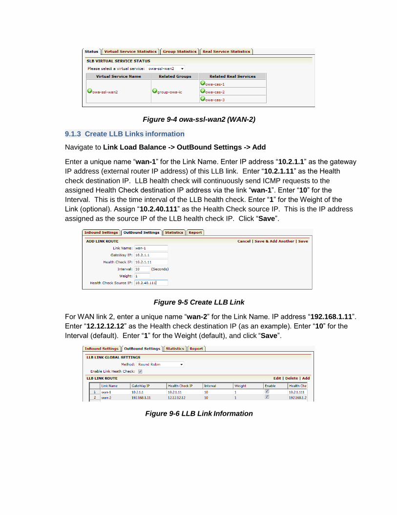
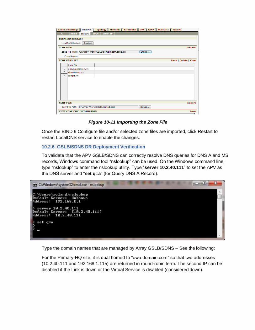
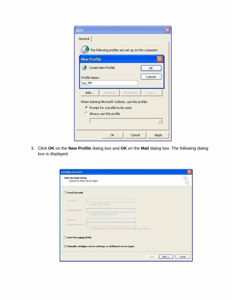
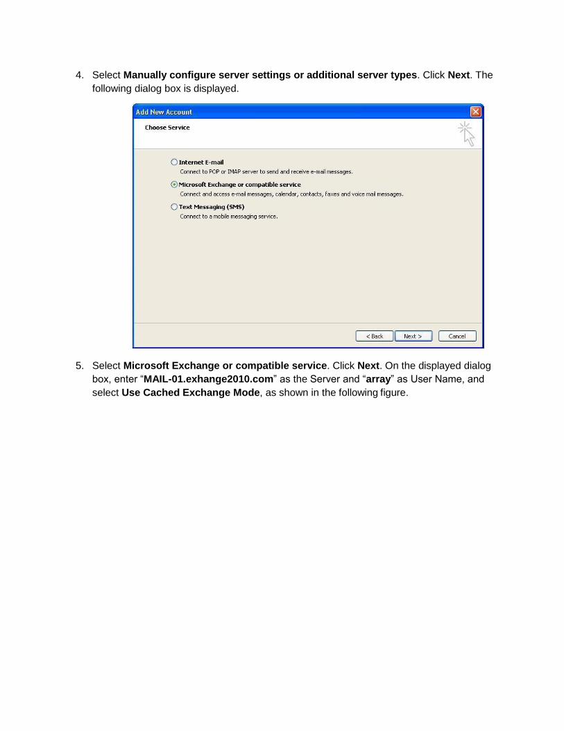
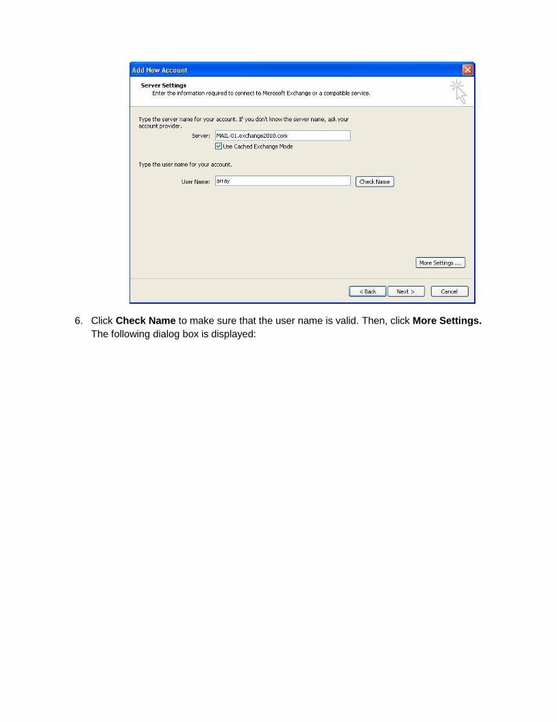
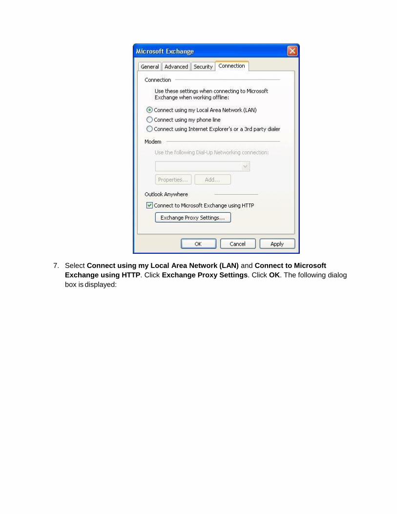
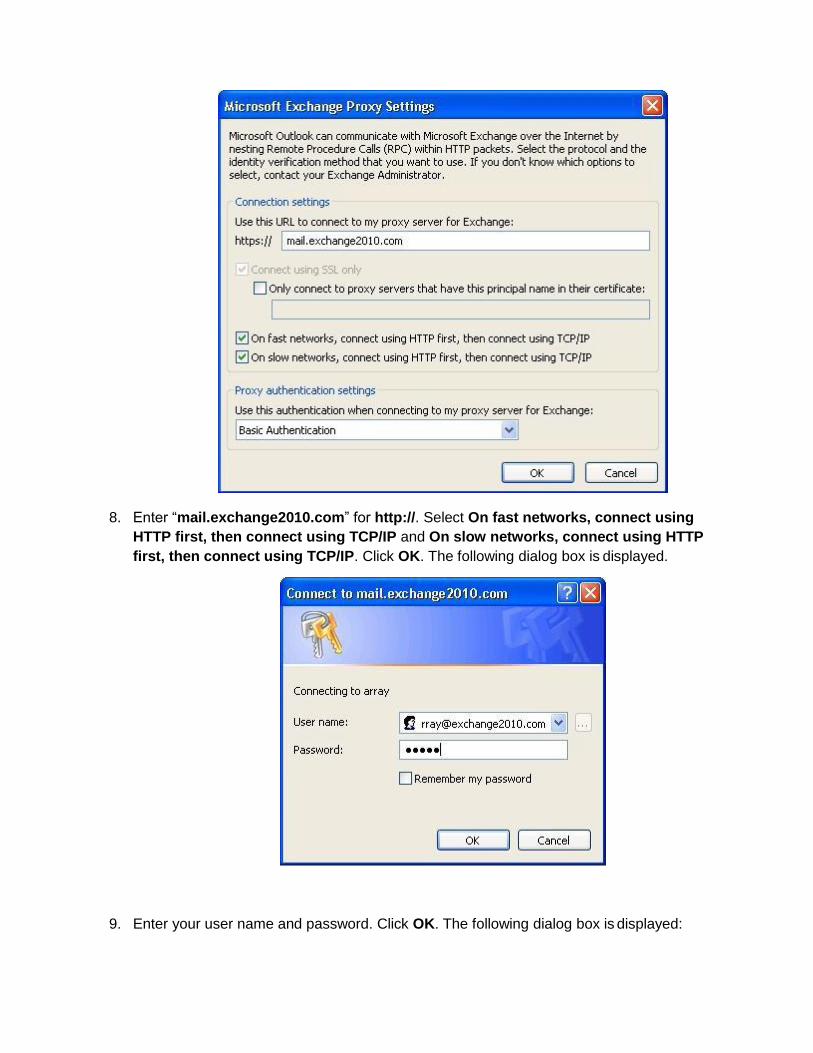


